Embed Size (px)
Citation preview
Gearmotors \ Industrial Gear Units \ Drive Electronics \ Drive Automation \ Services
Modular Engineering Software System MotionStudioMOVITRANS® Parameter Tree
ManualEdition 08/200711532211 / EN

SEW-EURODRIVE – Driving the world

Manual – Modular Engineering Software System MotionStudio MOVITRANS® Parameter Tree 3
Contents
Contents1 Important Notes................................................................................................... 4
1.1 Safety and warning instructions .................................................................. 41.2 Designated use ........................................................................................... 51.3 Operational environment............................................................................. 51.4 Disposal ...................................................................................................... 5
2 Index of Changes ................................................................................................ 62.1 Changes to the previous version ................................................................ 6
3 Introduction ......................................................................................................... 73.1 What is MOVITOOLS® MotionStudio?........................................................ 73.2 Application areas ........................................................................................ 73.3 Communication ........................................................................................... 73.4 Serial interface type USS21A (RS-232)...................................................... 8
4 Structure .............................................................................................................. 94.1 Screen layout ............................................................................................ 94.2 User interface ............................................................................................. 9
5 Operation ........................................................................................................... 115.1 Prerequisites ............................................................................................. 115.2 Starting the program ................................................................................ 115.3 Exiting the program................................................................................... 12
6 Parameters......................................................................................................... 136.1 Unit data.................................................................................................... 136.2 Process values.......................................................................................... 146.3 Min. / max. values ..................................................................................... 176.4 Error memory ............................................................................................ 186.5 Compensation........................................................................................... 196.6 Reset response......................................................................................... 206.7 Setpoint selection...................................................................................... 226.8 Binary outputs ........................................................................................... 256.9 Serial communication................................................................................ 266.10 Modulation ................................................................................................ 286.11 Setup......................................................................................................... 306.12 Process data description........................................................................... 316.13 Error responses ........................................................................................ 326.14 Manual operation ...................................................................................... 33
7 Service ............................................................................................................... 357.1 Error overview........................................................................................... 35
8 Address List ...................................................................................................... 36
Index ................................................................................................................... 45

4 Manual – Modular Engineering Software System MotionStudio MOVITRANS® Parameter Tree
1 Safety and warning instructionsImportant Notes
1 Important Notes1.1 Safety and warning instructions
Always comply with the safety and warning instructions in this publication.
Therefore, you should read the operating instructions for the individual components be-fore installing the MOVITOOLS® MotionStudio startup software and starting theMOVITRANS® TPS10A stationary converter.
HazardIndicates an imminently hazardous situation which, if not avoided, WILL result in deathor serious injury.
WarningIndicates an imminently hazardous situation caused by the product which, if notavoided, WILL result in death or serious injury. This symbol also indicates potential fordamage to property.
CautionIndicates a potentially hazardous situation which, if not avoided, MAY result in minor in-jury or damage to products.
NoteIndicates a reference to useful information, e.g. on startup.
Documentation referenceIndicates a reference to a document, such as operating instructions, a catalog or a datasheet.
You must adhere to the operating instructions to ensure:
• Fault-free operation
• Fulfillment of any rights to claim under limited warranty

Manual – Modular Engineering Software System MotionStudio MOVITRANS® Parameter Tree 5
1Designated useImportant Notes
1.2 Designated use
MOVITRANS® TPS10A stationary converters are designed to be installed in controlcabinets. Observe all information on the technical data and the permitted conditionswhere the unit is operated.
Do not operate the unit until you have established that the machine complies with theEMC Directive 89/336/EEC and that the conformity of the end product has been deter-mined in accordance with the Machinery Directive 89/392/EEC (with reference to EN60204).
The rules and regulations of the Professional Association ["Berufsgenossenschaft" -BG], in particular BG rules B11 concerning electromagnetic fields, must be observedduring installation, startup and operation of systems with contactless energy transfer byinduction for use in industrial workplaces.
1.3 Operational environmentThe following uses are prohibited, unless measures are expressly taken to make thempossible:
1.4 DisposalPlease follow the current regulations: Dispose of the following materials in accordancewith the regulations in force:
• Electronics scrap (circuit boards)
• Plastic (housing)
• Sheet metal
• Copper
etc.
MOVITRANS® TPS10A stationary converters are intended for use in industrial and com-mercial systems for the operation of contactless power transmission systems. Only con-nect the stipulated and suitable components to the stationary converter.
• In areas with explosion-hazard
• In areas exposed to harmful oils, acids, gases, vapors, dust, radiation, etc.
• In non-stationary applications with mechanical vibration and shock loads exceedingthe values stipulated in EN 50178.

6 Manual – Modular Engineering Software System MotionStudio MOVITRANS® Parameter Tree
2 Changes to the previous versionIndex of Changes
2 Index of Changes2.1 Changes to the previous version
The following section lists the changes made to the individual sections from the previousversion "MOVITRANS® Shell TPS Startup Software Version 1.0", publication number11272716 (EN).
Overview
• The section "Installation" has been removed.
Operation
• The following subsections were removed from the section "Operation":
– Establishing a connection
– Ending the connection
– Changing the interface
– Function call
Functions
• The following parameters were added to the section "Functions":
– Setpoint selection
– Binary output
– Serial communication
– Modulation
– Setup
– Process data description
– Fault responses
– Manual operation
– List of errors

Manual – Modular Engineering Software System MotionStudio MOVITRANS® Parameter Tree 7
3What is MOVITOOLS® MotionStudio?Introduction
3 Introduction3.1 What is MOVITOOLS® MotionStudio?3.1.1 Description
The MOVITOOLS® MotionStudio startup software is an engineering software for pro-gramming, parameter setting and diagnostics of all electronics products from SEW-EURODRIVE.
3.1.2 System requirementsThe following requirements must be fulfilled for installing the MOVITOOLS®
MotionStudio startup software:
• Microsoft Windows 2000 Professional with Service Pack 3 or Windows XPProfessional is installed on the computer.
• .NET Framework SDK 2.0 is installed on the computer.
Once you have installed MOVITOOLS®MotionStudio, you will find the correspondingentries in the Windows start menu at the following path:
• Start/Programs/SEW/MOVITOOLS_MotionStudio
3.2 Application areas3.2.1 Use
You can use the MOVITOOLS® MotionStudio software together with the MOVITRANS®
parameter tree to display the current process and display values or diagnostic propertiesand to read or change parameters, e.g. for:
• Track compensation at startup
• Parameter setting during startup
• Fault diagnostics and storage for solving problems
3.3 CommunicationCommunication between the MOVITRANS® TPS10A stationary converter and the hostcomputer (PC or notebook) takes place via a serial interface.
The MOVITRANS® TPS10A stationary converter must be fitted with an isolatedUSS21A (RS-232) interface and the host computer must have a free serial port.

8 Manual – Modular Engineering Software System MotionStudio MOVITRANS® Parameter Tree
3 Serial interface type USS21A (RS-232)Introduction
3.4 Serial interface type USS21A (RS-232)3.4.1 Description
The USS21A (RS-232) serial interface is designed as a 9-pin sub-D socket (EIA stan-dard) and fitted in a housing to be plugged into the inverter (TERMINAL slot). The optioncan be plugged in during operation. The transmission rate of the RS-232 interface is9600 baud.
3.4.2 ConnectionUse a commercial-available, serial, shielded interface cable with 1:1 connection to con-nect the host computer (PC or notebook) to the USS21A (RS-232) serial interface.
520342411
RxD
TxD2233
55
max. 5 m
USS21A PC COM 1-4
55
3322 2
3
55
32
9-pole sub D socket9-pole sub D plug
GND (ground)

Manual – Modular Engineering Software System MotionStudio MOVITRANS® Parameter Tree 9
4Screen layoutStructure
4 Structure4.1 Screen layout
The MOVITOOLS® MotionStudio software interface is displayed when you start the pro-gram. The following figure shows the MOVITRANS® parameter tree view:
How to get to this view is described on (page 11).
4.2 User interface 4.2.1 Elements
The user interface of the MOVITRANS® parameter tree view of the MOVITOOLS®
MotionStudio contains the "Parameter tree" tab page, the parameter tree and the workand display area. The following sections describe the functions and options availablewith these elements:
516265867
[1]
[2]
[3]
[1] "Parameter tree" tab page[2] Parameter tree[3] Work and display area

10 Manual – Modular Engineering Software System MotionStudio MOVITRANS® Parameter Tree
4 User interfaceStructure
4.2.2 "Parameter tree" tab page
The "Parameter tree" tab page contains the icon and the name of the unit and the inter-face address. The current RS-485 connection address is displayed before the name ofthe program.
4.2.3 Parameter treeThe parameter tree contains a list of all possible display windows. Double-click on a listentry to open it.
4.2.4 Work and display areaThe windows containing display values, startup data and the unit functions of the con-nected MOVITRANS® TPS10A stationary converter are displayed here.
Double-click on a window to open it.
In the three groups "Display values", "Startup" and "Unit functions", the following infor-mation windows can be displayed individually or simultaneously:
• Display values
– Unit data
– Process values
– Min. / max. values
– Fault memory (t-0, t-1, t-2, t-3 and t-4)
• Startup
– Compensation
• Unit functions
– Reset behavior
– Setpoint selection
– Binary outputs
– Serial communication
– Modulation
– Setup
– Process data description
– Fault responses
• Manual operation

Manual – Modular Engineering Software System MotionStudio MOVITRANS® Parameter Tree 11
5PrerequisitesOperation
5 Operation5.1 Prerequisites
Ensure that the following requirements have been met:
• The TPS10A stationary converter must be fitted with a USS21A (RS-232) serialinterface.
• The host computer (e.g. PC or notebook) must be connected to the TPS10Astationary converter using a commercially available serial interface.
• Both devices must be switched on.
5.2 Starting the program 5.2.1 Instructions
Proceed as follows to start the MOVITOOLS® MotionStudio software:
1. Start MOVITOOLS® MotionStudio on the host computer by clicking on the relevantentry in the start menu:
• Start/Program/SEW/MOVITOOLS® MotionStudio/MOVITOOLS® MotionStudio5.XX
You can also change the language settings. To do so, click on "Settings" / "Lan-guage" in the menu bar. Select the required language, e.g. "German".
2. After starting the program, you are prompted to create a new project. Choose ameaningful name and click on "OK".
3. You are prompted to create a new network. Create a new network and confirm with"OK".
4. Configure the communication connections (e.g. serial, COM port 1, 9600 kB).
5. Click on the [Scan] button after completing the configuration. The connected unitsare now displayed.
6. Right-click on the connected unit, e.g. "TPS10A040-503".
7. Open the parameter tree view by clicking on "Parameter tree" in the displayed con-text menu.
Only connected units that are switched on are displayed in the table. If the unit is notdetected, check the requirements:
• Check the serial connection between the unit and the host computer.
• Make sure that the TPS10A stationary converter is switched on.

12 Manual – Modular Engineering Software System MotionStudio MOVITRANS® Parameter Tree
5 Exiting the programOperation
5.3 Exiting the program5.3.1 Instructions
For exiting the MOVITOOLS® MotionStudio software, you have the following options:
• Select "Exit" from the "Project" menu.
• Use the "Close" icon from the window control.
• Hold the <Alt> key down and press the <F4> function key.
Manual – Modular Engineering Software System MotionStudio MOVITRANS® Parameter Tree 13
6Unit dataParameters
6 ParametersThe following section describes the information windows in the MOVITRANS® parame-ter tree view with the display values for start up and the unit functions.
The following sections contain the parameter descriptions. The parameter namescorrespond to those displayed in MOVITOOLS® MotionStudio.
The factory setting is indicated in bold.
6.1 Unit data6.1.1 Display
Proceed as follows to display the unit data:
1. Double-click on the "Unit data" entry in the parameter tree view in the list "Displayvalues".
The "Unit data" window is displayed:
6.1.2 Meaning The following information is displayed in the "Unit data" window:
• Unit type [1]
Here, the connected type of the TPS10A stationary converter is displayed.
• Unit series [2]
The connected unit series is displayed here.
• Power section [3]
Here, the rated power of the connected TPS10A stationary converter is displayed.
• Firmware [4]
The part number of the used firmware is displayed here.
267636747
[1] Display field "Unit type"[2] Display field "Unit series"[3] Display field "Power section"[4] Display field "Firmware"
[1]
[2]
[3]
[4]

14 Manual – Modular Engineering Software System MotionStudio MOVITRANS® Parameter Tree
6 Process valuesParameters
6.2 Process values6.2.1 Display
Proceed as follows to display the process values:
1. Double-click on the "Process values" entry in the parameter tree view in the list"Display values".
The "Process values" window is displayed:
6.2.2 Meaning The following information is displayed in the "Process values" window:
• Error code [1]
The current fault status is displayed here by the respective error code. If an error hasoccurred, another field with the designation "Subcode" appears below the "Code"field. For a complete list of all possible error messages with error causes and reme-dial measures, refer to the error overview, (page 35).
266977163
[1] Display field "Error code"[2] Display field "Output stage"[3] Display field "Operating mode"[4] Display field "Setpoint"[5] Display field "Ramp time"[6] Display field "Output voltage"[7] Display field "Output current"[8] Display field "Load current"[9] Display field "Load current fluctuation"[10] Display field "Heat sink temperature"[11] Display field "Capacity utilization"[12] Display field "DC link voltage"[13] Display field "DC link ripple"
[1]
[2]
[3]
[4]
[5]
[6]
[7]
[8]
[9]
[10]
[11]
[12]
[13]

Manual – Modular Engineering Software System MotionStudio MOVITRANS® Parameter Tree 15
6Process valuesParameters
• Output stage [2]
The status of the output stage is displayed here. The following display values arepossible:
– Inhibited
The output stage is currently inhibited.
– Enabled
The output stage is currently enabled.
The status of the output stage can be influenced by a control command (e.g. terminalDI00) or occurring errors.
• Operating mode [3]
The current operating mode is displayed here. The following display values are pos-sible:
– Voltage control
The TPS10A stationary converter is in "Voltage control" operating mode.
– Current control
The TPS10A stationary converter is in "Current control" operating mode.
SEW EURODRIVE recommends to activate current control. The operating mode isset via terminals (DI03) or the control word (bit 3) depending on the control signalsource.
• Setpoint [4]
The setpoint selection for the current is displayed here. The adjusted setpoint is se-lected depending on the setpoint source or control signal source / fixed setpoints.The following is an example of a setpoint specification:
– 7.5 A 100.0% digital I11
The percentages of the current setpoint are based on the values of the nominalload current IL. The above values are examples of setpoints for a 4 kW TPS10Astationary converter with a nominal load current of IL = 7.5 Aeff.
• Ramp time [5]
The ramp time is displayed here. The ramp times are set in the setpoint selection win-dow in the "Unit functions" parameter group.
For more information on this topic, refer to the "Startup" and "Service" sections in the"MOVITRANS TPS10A Stationary Converter" operating instructions.
16 Manual – Modular Engineering Software System MotionStudio MOVITRANS® Parameter Tree
6 Process valuesParameters
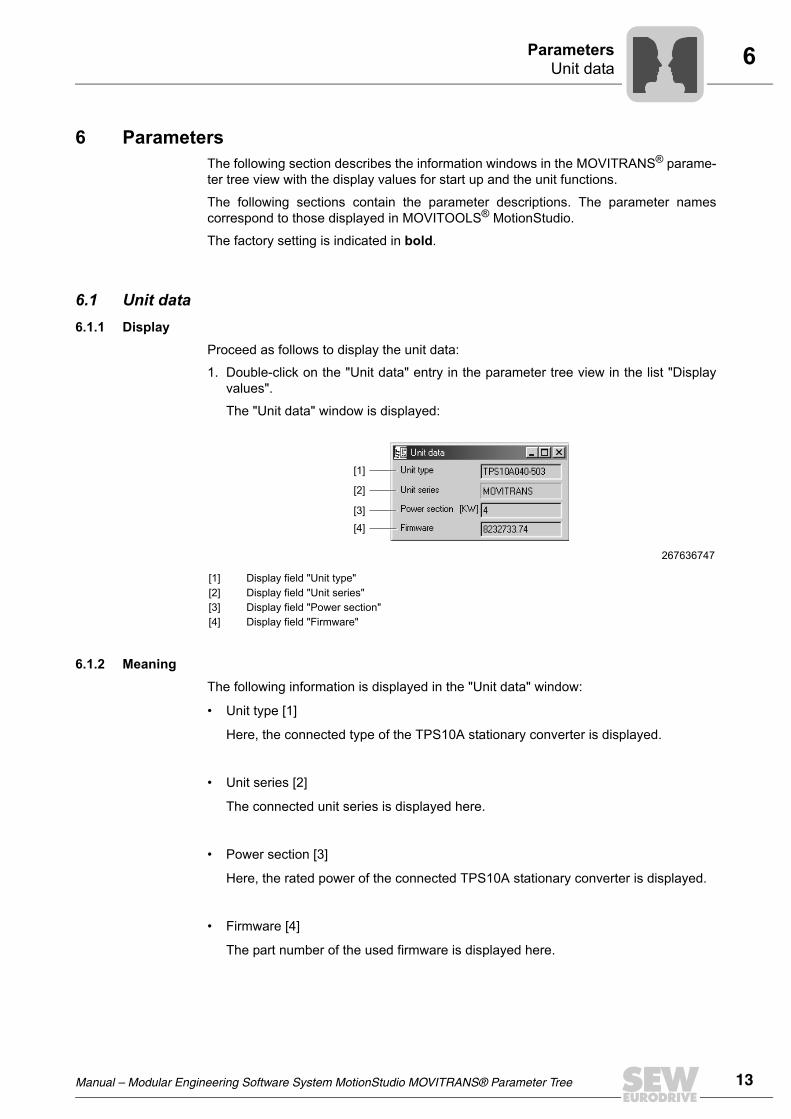
• Output voltage [6]
Here, the r.m.s. value of the output voltage of the TPS10A stationary converter is dis-played.
• Output current [7]
The r.m.s. value of the output current IG is displayed here. The TPS10A stationaryconverter uses this current for supplying the TAS transformer module. The outputcurrent is proportional to the transferred apparent power. The reactive power con-sumption is minimized by track compensation , which means that the output currentis basically proportional to the output power.
• Load current [8]
The r.m.s. value of the load current IL is displayed here. A so-called gyrator circuit inthe TAS transformer module provides for a constant load current independent of theload. The load current is set via setpoint selection. The transformation ratio of the so-called matching transformer in the TAS transformer module ensures that for a select-ed setpoint of 100 % IL, the rated output current of the transformer module is flowing(e.g. 60 Aeff or 85 Aeff).
• Load current fluctuation [9]
The load current fluctuation is displayed here.
The load current fluctuation represents the fluctuation range of the load currentbased on the value of the nominal load current (Δ IL / IL).
• Heat sink temperature [10]
The heat sink temperature is displayed here.
• Capacity utilization [11]
The capacity utilization is displayed here.
The capacity utilization is the present unit output current based on the maximum per-mitted unit output current. When the unit reaches a capacity utilization of 100%, theunit switches off and outputs the error message "Overcurrent error".
• DC link voltage [12]
The DC link voltage is displayed here.
• DC link ripple [13]
The DC link ripple is displayed here. The DC link ripple represents the fluctuationrange of the DC link voltage.
For more information on this topic, refer to the "Operation" and "Service" sections in the"MOVITRANS® TPS10A Stationary Converter" operating instructions.

Manual – Modular Engineering Software System MotionStudio MOVITRANS® Parameter Tree 17
6Min. / max. valuesParameters
6.3 Min. / max. valuesThe minimum and maximum process values, recorded since the last time the unit wasswitched on, are stored in the "Min. / max. values" window.
6.3.1 DisplayProceed as follows to display the Min. / max. values:
1. Double-click on the "Min. / max. values" entry in the parameter tree view in the list"Display values".
The "Min. / max. values" window is displayed:
6.3.2 MeaningThe minimum and maximum process values are stored in the "Min. / max. values"window.
6.3.3 ResetTo reset these values to the current process values, press the reset button. There aretwo ways to reset the min. / max. values:
1. Select the option "Min. / max. values" in the "Min. / max. values" window in the se-lection list "Reset statistic data" [9].
2. Select the option "Min. / max. values" in the "Setup" window in the selection list"Reset statistic data".
266974987
[1] Display field "Output voltage"[2] Display field "Output current"[3] Display field "Load current"[4] Display field "Load current fluctuation"[5] Display field "Heat sink temperature"[6] Display field "Capacity utilization"[7] Display field "DC link voltage"[8] Display field "DC link ripple"[9] Selection list "Reset statistics data"
[1]
[2]
[3]
[4]
[5]
[6]
[7]
[8]
[9]

18 Manual – Modular Engineering Software System MotionStudio MOVITRANS® Parameter Tree
6 Error memoryParameters
6.4 Error memoryThe TPS10A stationary converter can store several faults. 5 error memories (t-0, t-1, t-2,t-3 and t-4) are available.
The errors are stored in chronological order with the most recent error event beingstored in error memory t-0. If more than five errors occur, the oldest error, which is storedin error memory t-4, is deleted.
6.4.1 DisplayProceed as follows to display the error memories:
1. Double-click on the "Error memory t-0" entry, for example, in the parameter tree viewin the list "Display values".
The "Error memory t-0" window is displayed:
266979339
[1] Display field "Error code"[2] Display field "Output stage"[3] Display field "Operating mode"[4] Display field "Setpoint"[5] Display field "Ramp time"[6] Display field "Output voltage"[7] Display field "Output current"[8] Display field "Load current"[9] Display field "Load current fluctuation"[10] Display field "Heat sink temperature"[11] Display field "Capacity utilization"[12] Display field "DC link voltage"[13] Display field "DC link ripple"
[1]
[2]
[3]
[4]
[5]
[6]
[7]
[8]
[9]
[10]
[11]
[12]
[13]

Manual – Modular Engineering Software System MotionStudio MOVITRANS® Parameter Tree 19
6CompensationParameters
6.4.2 Error event
The information that is determined when an error occurs is displayed in the "Errormemory t-x" window and stored in the error memory "t-x". The display fields are identicalwith those of the "Process values" window.
6.5 CompensationThe "Compensation" window is used during the startup of the TPS10A stationary con-verter to support the compensation of the line conductor.
6.5.1 DisplayProceed as follows to display the current compensation errors:
1. Double-click on the "Compensation" entry in the parameter tree view in the "Startup"list.
The "Compensation" window is displayed:
6.5.2 MeaningThe following compensation data is set or displayed in the "Compensation" window:
• Nominal line conductor current [1]
The nominal line conductor current at 100 % setpoint is displayed here.
For more information on the display values and what they mean, refer to the section"Process values".
To achieve the best measuring results it is important that no real power is transferredduring the measurement.
For more information on this topic, refer to the "Startup" section of the "MOVITRANS®
TPS10A Stationary Converter" operating instructions.
266972811
[1] Entry field "Nominal line conductor current"[2] Display field "Relative compensation error"[3] Display field "Absolute compensation error"
[1]
[2]
[3]

20 Manual – Modular Engineering Software System MotionStudio MOVITRANS® Parameter Tree
6 Reset responseParameters
In the line conductor current field, enter the line conductor current for the system inquestion (rated output current of the MOVITRANS® TAS10A transformer module).This value is used to calculate the absolute compensation error correctly.
• Relative compensation error [2]
The relative compensation error is displayed here (Δr = output current / load currentin %).
• Absolute compensation error [3]
The absolute compensation error is displayed here.
6.6 Reset responseInformation on the reset function is displayed in the "Reset response" window.
You can use the reset function to reset errors that occur in the TPS10A stationary con-verter automatically after a set time.
6.6.1 DisplayProceed as follows to display the reset information:
1. Double-click on the "Reset response" entry in the parameter tree view in the "Unitfunctions" list.
The window "Reset response" is displayed:
6.6.2 Meaning The following information is displayed in the "Reset response" window:
• Auto reset [1]
The current status of the auto reset function is displayed here. The following displayvalues are possible:
The auto reset function must not be used in systems where the automatic restart repre-sents a risk of injury to persons or damage to equipment!
For more information on this topic, refer to the "Service" section (auto reset function) ofthe "MOVITRANS® TPS10A Stationary Converter" operating instructions.
266970635
[1] Display field "Auto reset"[2] Display field "Reset counter"[3] Display field "Restart time"
[2]
[3]
[4]

Manual – Modular Engineering Software System MotionStudio MOVITRANS® Parameter Tree 21
6Reset responseParameters
– On
The auto reset function is activated. In case of an error, this function automaticallyresets the unit after a pre-defined time of 50 ms (restart time). A maximum of 3auto resets are possible during an auto reset phase. If more than 3 errors occurthat are reset by an auto reset, no more auto resets are possible until one of thefollowing actions has been carried out:
– An error reset as described in section "Error reset"
– The unit is completely switched off and then on again
Now, auto reset is possible again.
The following faults can be reset:
– Error "Overcurrent"
– Error "Overtemperature"
– Off
The auto reset function is deactivated.
There are 3 different ways to set the auto reset function depending on the set controlsignal source:
• Control signal source = "Terminals": The auto reset function can be activated(DI02 = "1") or deactivated (DI02 = "0") via binary input DI02.
• Control signal source = "SBus control word": The auto reset function is activatedand deactivated via bit 2 of the control word.
• Control signal source = "Parameter control word": The auto reset function isactivated and deactivated via bit 2 of the control word.
• Reset counter [2]
The number of resets possible is displayed here.
When the auto reset function is activated, up to 3 automatic resets are possible.
• Restart time [3]
The restart time; that is, the interval between the time when the fault and occurs andthe time it is reset, is displayed here.
The restart time is set to 50 ms.
The auto reset function must not be used in systems where the automatic restart repre-sents a risk of injury to persons or damage to equipment!
For more information on this topic, refer to the "Startup" section of the "MOVITRANS®
TPS10A Stationary Converter" operating instructions.
22 Manual – Modular Engineering Software System MotionStudio MOVITRANS® Parameter Tree
6 Setpoint selectionParameters
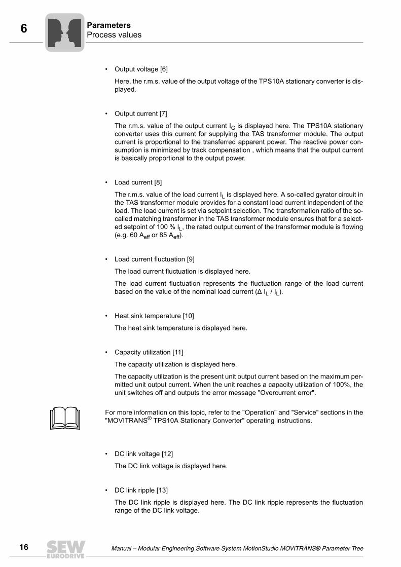
6.7 Setpoint selectionSetpoint and control information can be displayed and set in the "Setpoint selection"window.
6.7.1 DisplayProceed as follows to display the setpoint data:
1. Double-click on the "Setpoint selection" entry in the parameter tree view in the "Unitfunctions" list.
The "Setpoint selection" window is displayed:
267621515
[1] Selection list "Setpoint source"[2] Selection list "Control signal source"[3] Entry field "Analog / setpoint reference I00"[4]...[6]
Entry fields "Fixed setpoint IXX"
[7]...[10]
Selection list "Ramp time TXX"
[11]...[14]
Selection list "Pulse mode PXX"
[1]
[2]
[3]
[4]
[5]
[6]
[7]
[8]
[9]
[10]
[11]
[12]
[13]
[14]
Manual – Modular Engineering Software System MotionStudio MOVITRANS® Parameter Tree 23
6Setpoint selectionParameters
6.7.2 Meaning
The following information can be set in the "Setpoint selection" window:
• Setpoint source [1]
This parameter sets the source from which the TPS10A stationary converter receivesthe setpoint with ramp time and pulse mode.
The following options can be selected:
– Fixed setpoint / AI01
The setpoint is provided by the analog input (AI01) or the fixed setpoints.
The setpoint IXX is selected by the activated control signal source:
– Via terminals DI04, DI05 (control signal source: terminals),
– Via bit 4 and bit 5 of the control word from the process output data PO1 (controlsignal source: SBus 1), or
– Via bit 4 and bit 5 of the parameter control word (control signal source:parameter control word).
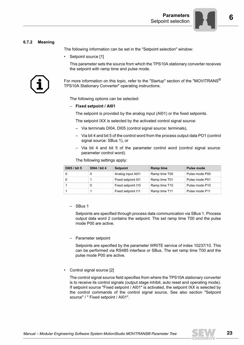
The following settings apply:
– SBus 1
Setpoints are specified through process data communication via SBus 1. Processoutput data word 2 contains the setpoint. The set ramp time T00 and the pulsemode P00 are active.
– Parameter setpoint
Setpoints are specified by the parameter WRITE service of index 10237/10. Thiscan be performed via RS485 interface or SBus. The set ramp time T00 and thepulse mode P00 are active.
• Control signal source [2]
The control signal source field specifies from where the TPS10A stationary converteris to receive its control signals (output stage inhibit, auto reset and operating mode).If setpoint source "Fixed setpoint / AI01" is activated, the setpoint IXX is selected bythe control commands of the control signal source. See also section "Setpointsource" / " Fixed setpoint / AI01".
For more information on this topic, refer to the "Startup" section of the "MOVITRANS®
TPS10A Stationary Converter" operating instructions.
DI05 / bit 5 DI04 / bit 4 Setpoint Ramp time Pulse mode
0 0 Analog input AI01 Ramp time T00 Pulse mode P00
0 1 Fixed setpoint I01 Ramp time T01 Pulse mode P01
1 0 Fixed setpoint I10 Ramp time T10 Pulse mode P10
1 1 Fixed setpoint I11 Ramp time T11 Pulse mode P11

24 Manual – Modular Engineering Software System MotionStudio MOVITRANS® Parameter Tree
6 Setpoint selectionParameters
The following control signal sources can be set:
– Terminals
Control is performed via the binary inputs.
– SBus 1
Control takes place via cyclical SBus process data communication and the binaryinputs. The control commands are transferred to the unit via control word 1 (PO1).
– Parameter control word
Control takes place through a parameter WRITE service via SBus or the RS485interface and the binary inputs.
• Analog setpoint reference I00 [3]
Setting range: 100..150% IL.
The analog setpoint reference I00 defines the setting range of the analog input(AI01): -10 ...+10 V (-40...+40 mA) = 0 ...I00 [% IL].
• Fixed setpoint IXX [4]..[6]
Setting range: 0..150% IL.
• Ramp time TXX [7]..[10]
Here, the ramp time (tR) is set. You can choose from the following pre-defined ramptimes: 20 ms, 100 ms, 200 ms, 600 ms, 1700 ms and 3500 ms.
The ramp time is based on a setpoint difference of 100%. In case of a setpointchange, the drive moves to the new setpoint using the respective ramp.
• Pulse mode PXX [11]..[14]
The pulse mode is used for specifying the cyclic duration factor or the intervals of thesupply. Depending on the power demand of the mobile consumers, reduced cyclicduration factors can also be activated.
482023435
t [ms]
IL
0
tR
100% IL
50% IL

Manual – Modular Engineering Software System MotionStudio MOVITRANS® Parameter Tree 25
6Binary outputsParameters
You can choose from the following four pulse modes:
– Cdf100: Cyclic duration factor is 100%, no pulsing
– Cdf95: Cyclic duration factor is 95%
– Cdf67: Cyclic duration factor is 67%
– Cdf20: Cyclic duration factor is 20%
6.8 Binary outputsIn the "Binary outputs" window, you can make settings for the binary outputs.
6.8.1 DisplayProceed as follows to display the "Binary outputs" window:
1. Double-click on the "Binary outputs" entry in the parameter tree view in the "Unitfunctions" list.
The "Binary outputs" window is displayed:
6.8.2 MeaningIn the "Binary outputs" window, functions can be assigned to both outputs.
• Binary outputs DO0X [1] / [2]
The following functions can be assigned to the binary outputs:
267625867
[1] / [2] Selection list "Binary outputs DO0X"
[1]
[2]
FunctionBinary output
factory set to"0" signal "1" signal
No function always "0" signal -- --
Malfunction, 0-active Collective fault signal No malfunction DO02
Ready for operation Not ready for operation Ready for operation DO00
Current reference mes-sage
ILoad < IXX setpoint not reached
ILoad < IXX setpoint reached
--
Voltage limit message Voltage limit not reached Voltage limit reached --
26 Manual – Modular Engineering Software System MotionStudio MOVITRANS® Parameter Tree
6 Serial communicationParameters
6.9 Serial communicationIn the "Serial communication" window, addresses and communication data are set.
6.9.1 DisplayProceed as follows to display the serial communication settings:
1. Double-click on the "Serial communication" entry in the parameter tree view in the"Unit functions" list.
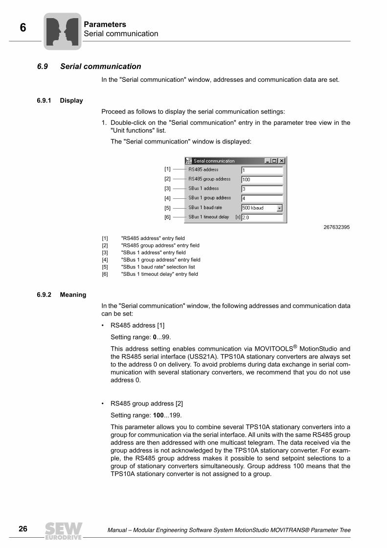
The "Serial communication" window is displayed:
6.9.2 MeaningIn the "Serial communication" window, the following addresses and communication datacan be set:
• RS485 address [1]
Setting range: 0...99.
This address setting enables communication via MOVITOOLS® MotionStudio andthe RS485 serial interface (USS21A). TPS10A stationary converters are always setto the address 0 on delivery. To avoid problems during data exchange in serial com-munication with several stationary converters, we recommend that you do not useaddress 0.
• RS485 group address [2]
Setting range: 100...199.
This parameter allows you to combine several TPS10A stationary converters into agroup for communication via the serial interface. All units with the same RS485 groupaddress are then addressed with one multicast telegram. The data received via thegroup address is not acknowledged by the TPS10A stationary converter. For exam-ple, the RS485 group address makes it possible to send setpoint selections to agroup of stationary converters simultaneously. Group address 100 means that theTPS10A stationary converter is not assigned to a group.
267632395
[1] "RS485 address" entry field[2] "RS485 group address" entry field[3] "SBus 1 address" entry field[4] "SBus 1 group address" entry field[5] "SBus 1 baud rate" selection list[6] "SBus 1 timeout delay" entry field
[1]
[2]
[3]
[4]
[5]
[6]
Manual – Modular Engineering Software System MotionStudio MOVITRANS® Parameter Tree 27
6Serial communicationParameters
• SBus 1 address [3]
Setting range: 0...63.
Here, the system bus address of the TPS10A stationary converter is set.
• SBus 1 group address [4]
Setting range: 0...63. Here, the system bus group address for multicast telegrams ofthe stationary converter is set.
• SBus 1 baud rate [5]
Setting range: 125; 250; 500; 1000 kBaud.
This parameter is used for setting the baud rate of the system bus.
• SBus 1 timeout delay [6]
Setting range: 0...650 s.
This parameter sets the monitoring time for cyclical data transmission via the systembus. If no cyclical data transfer (process data communication) takes place during theset time via the system bus, the TPS10A stationary converter executes the set errorresponse. See parameter Response SBus timeout. No monitoring of cyclic datatransmission via the system bus takes place when the SBus timeout delay is set tothe value "0".

28 Manual – Modular Engineering Software System MotionStudio MOVITRANS® Parameter Tree
6 ModulationParameters
6.10 ModulationParameters for modulation are set in the "Modulation" window.
6.10.1 Display1. Double-click on the "Modulation" entry in the parameter tree view in the "Unit
functions" list.
The "Modulation" window is displayed:
6.10.2 MeaningParameters for modulation are set in the "Modulation" window.
• Frequency mode [1]
This parameter is used for setting the frequency of the line cable current of theTPS10A stationary converter.
The TPS10A stationary converter allows you to synchronize several supply units orto set a defined frequency shift between several supply units. For synchronization,the TPS10A stationary converters must be connected by a synchronization cable.
You can choose from the following frequency modes:
– 25.00 kHz - (master)
The output frequency of the stationary converter is 25.00 Hz. In synchronizationmode, this stationary converter is used as a master. It forwards the synchroniza-tion signal via the synchronization cable to the slaves. Only one master is permit-ted per synchronization network.
267628043
[1] Selection list "Frequency mode"[2] "Sync timeout response" selection list[3] "Sync phase angle" entry field[4] "Damping" selection list[5] "Load current fluctuation" entry field
[1]
[2]
[3]
[4]
[5]
For more information on this topic, refer to the "MOVITRANS® TPS10A StationaryConverter" operating instructions, part no. 11491426/EN.

Manual – Modular Engineering Software System MotionStudio MOVITRANS® Parameter Tree 29
6ModulationParameters
– Slave
The TPS10A stationary converter waits for the synchronization signal at the syn-chronization interface. The parameters Sync timeout response and Sync phaseangle are displayed as well. If the slave receives a faulty synchronization signal,or none at all, the TPS10A stationary converter executes the set error response.See parameter description "Response SBus timeout".
– 24.95 kHz
The output frequency of the stationary converter is 24.95 Hz. Synchronous oper-ation is not possible.
– 25.05 kHz
The output frequency of the stationary converter is 25.05 Hz. Synchronous oper-ation is not possible.
• Sync timeout response [2]
If the TPS10A stationary converter is in the "Slave" frequency mode and receives afaulty synchronization signal, or none at all, the error response set here is executed.
The following responses can be set:
• Sync phase angle [3]
Setting range: 0...360°.
In synchronous operation, the phase angle of the line cable current of a slave can bematched to that of the master. If the phase angle remains at factory setting 0°, thephase angles are the same. The setting 180° reverses the current direction.
• Damping
Setting range: On or off.
This parameter activates or deactivates a damping algorithm. If the load current fluc-tuation is high (> 5%), activate the damping function.
Response Description
No response The issued error is ignored, i.e. the error is not indicated, and no error response is executed.
Display only The error is displayed via the operation LED V3 and MOVITOOLS® MotionStudio. If the respective parameter is set, an error message is sent via the binary output terminals. Otherwise, the unit performs no error response. The error can be reset.
Output stage inhibit / locked
The TPS10A stationary converter performs an immediate switch-off. The corre-sponding error message is displayed, and the output stage is inhibited. If the respective parameter is set, the ready message is revoked via the binary out-put terminals. The stationary converter can only be enabled after the error has been reset.

30 Manual – Modular Engineering Software System MotionStudio MOVITRANS® Parameter Tree
6 SetupParameters
• Load current fluctuation
The load current fluctuation represents the fluctuation range of the load currentbased on the value of the nominal load current (�IL / IL).
6.11 SetupIn the "Setup" window, you can reset statistics and activate factory settings.
6.11.1 DisplayProceed as follows to display the "Setup" window:
1. Double-click on the "Setup" entry in the parameter tree view in the "Unit functions"list.
The "Setup" window is displayed:
6.11.2 MeaningIn the "Setup" window, you can reset statistics and activate factory settings.
• Reset statistics data
Selection: Error memory and min. / max. values.
The Reset statistic data parameter can be used for resetting the statistics of the errormemories stored in the EEPROM or the volatile min. / max. values.
• Factory setting
Selection: Standard.
Select factory settings (Standard) to reset the adjustable parameters stored in theEEPROM to the factory setting. In this case, the statistics are not reset. They mustbe reset separately via the Reset statistic data parameter.
267634571
[1] Selection list "Reset statistics data"[2] Selection list "Factory setting"
[1]
[2]

Manual – Modular Engineering Software System MotionStudio MOVITRANS® Parameter Tree 31
6Process data descriptionParameters
6.12 Process data descriptionThe content of the process data is displayed in the "Process data description" window.
6.12.1 Display1. Double-click on the "Process data description" entry in the parameter tree view in the
"Unit functions" list.
The "Process data description" window is displayed:
6.12.2 DescriptionThe content of the process data is displayed in the "Process data description" window.
The pre-defined contents of the process output data PO1 / PO2 / PO3 are displayedthrough the following parameters POX [1] to [3].
• Setpoint description PO1 [1]: Control word 1
• Setpoint description PO2 [2]: Current setpoint
• Setpoint description PO3 [3]: No function
The pre-defined contents of the process input data PI1 / PI2 / PI3 are displayedthrough the following parameters PIX [4] to [6].
• Setpoint description PI1 [4]: Status word 1
• Setpoint description PI2 [5]: Heat sink temperature
• Setpoint description PI3 [6]: Utilization
267630219
[1] Display field "Setpoint description PO1"[2] Display field "Setpoint description PO2"[3] Display field "Setpoint description PO3"[4] Display field "Actual value description PI1"[5] Display field "Actual value description PI2"[6] Display field "Actual value description PI3"
[1]
[2]
[3]
[4]
[5]
[6]
32 Manual – Modular Engineering Software System MotionStudio MOVITRANS® Parameter Tree
6 Error responsesParameters
6.13 Error responsesProgrammable error responses are set in the "Error responses" window.
6.13.1 Display1. Double-click on the "Error responses" entry in the parameter tree view in the "Unit
functions" list.
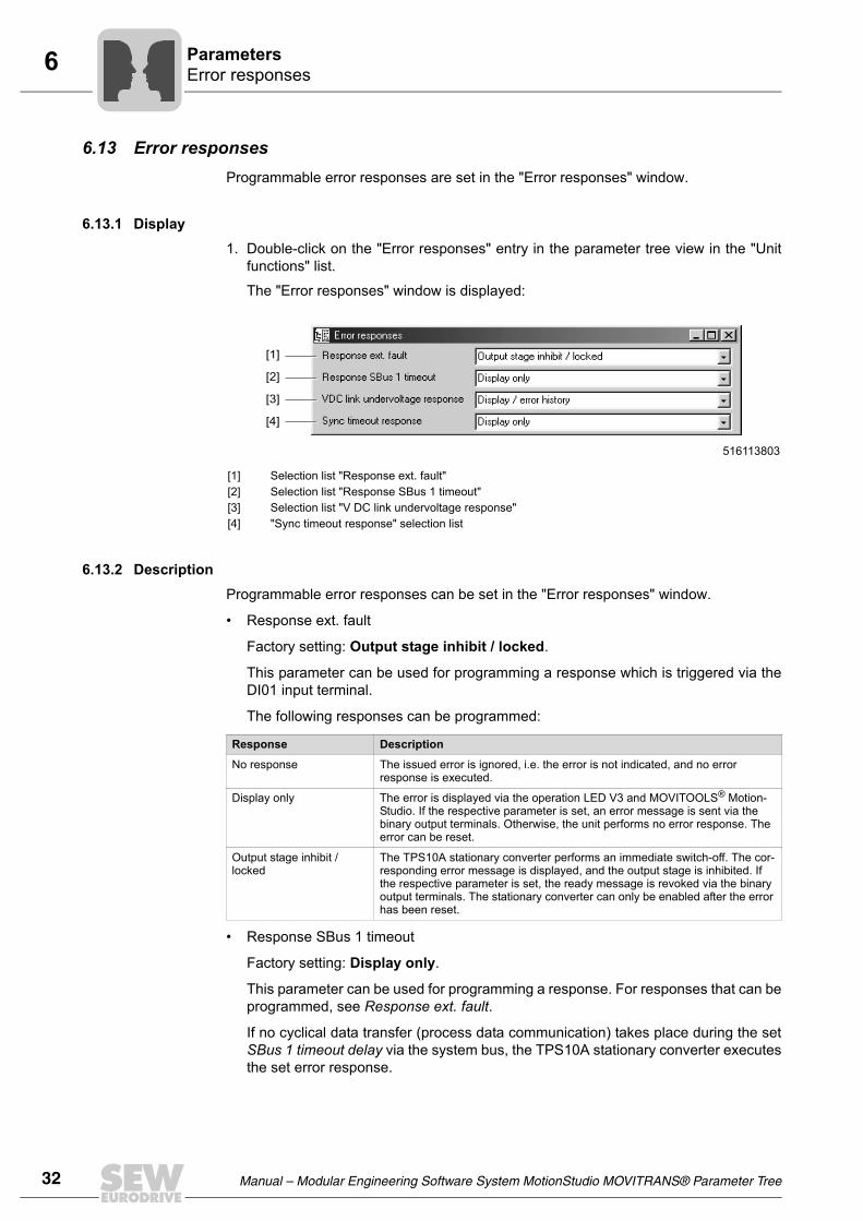
The "Error responses" window is displayed:
6.13.2 DescriptionProgrammable error responses can be set in the "Error responses" window.
• Response ext. fault
Factory setting: Output stage inhibit / locked.
This parameter can be used for programming a response which is triggered via theDI01 input terminal.
The following responses can be programmed:
• Response SBus 1 timeout
Factory setting: Display only.
This parameter can be used for programming a response. For responses that can beprogrammed, see Response ext. fault.
If no cyclical data transfer (process data communication) takes place during the setSBus 1 timeout delay via the system bus, the TPS10A stationary converter executesthe set error response.
516113803
[1] Selection list "Response ext. fault" [2] Selection list "Response SBus 1 timeout"[3] Selection list "V DC link undervoltage response"[4] "Sync timeout response" selection list
[1]
[2]
[3]
[4]
Response Description
No response The issued error is ignored, i.e. the error is not indicated, and no error response is executed.
Display only The error is displayed via the operation LED V3 and MOVITOOLS® Motion-Studio. If the respective parameter is set, an error message is sent via the binary output terminals. Otherwise, the unit performs no error response. The error can be reset.
Output stage inhibit / locked
The TPS10A stationary converter performs an immediate switch-off. The cor-responding error message is displayed, and the output stage is inhibited. If the respective parameter is set, the ready message is revoked via the binary output terminals. The stationary converter can only be enabled after the error has been reset.

Manual – Modular Engineering Software System MotionStudio MOVITRANS® Parameter Tree 33
6Manual operationParameters
• V DC link undervoltage response
Factory setting: Display / error history.
You can use this parameter for programming a response which is triggered in caseof V DC link undervoltage:
• Sync timeout response
Factory setting: Display only.
For responses that can be programmed, see Response ext. fault.
If the TPS10A stationary converter is in the "Slave" frequency mode and receives afaulty synchronization signal, or no signal at all, the error response set here is exe-cuted.
6.14 Manual operationIn the "Manual operation" window, the TPS10A stationary converter can be controlledmanually using a PC.
6.14.1 Display1. Double-click on the "Manual operation" entry in the parameter tree view in the "Unit
functions" list.
Response Description
No response The issued error is ignored, i.e. the error is not indicated, and no error response is executed (setting for 24 V backup mode).
Display only The error is displayed via the operation LED V3 and MOVITOOLS® Motion-Studio. If the respective parameter is set, an error message is sent via the binary output terminals. Otherwise, the unit performs no error response. The error can be reset.
Output stage inhibit / locked
The TPS10A stationary converter performs an immediate switch-off. The cor-responding error message is displayed, and the output stage is inhibited. If the respective parameter is set, the ready message is revoked via the binary output terminals. The stationary converter can only be enabled after the error has been reset.
Display / error history The error is displayed via the operation LED V3 and MOVITOOLS® Motion-Studio and is written into the error memory. If the respective parameter is set, an error message is sent via the binary output terminals. Otherwise, the unit performs no error response. The error can be reset.

34 Manual – Modular Engineering Software System MotionStudio MOVITRANS® Parameter Tree
6 Manual operationParameters
The "Manual operation" window is displayed:
6.14.2 DescriptionIn the "Manual operation" window, you can manually set control commands and set-points. The Manual operation mode supports the startup of the TPS10A stationary con-verter and the compensation of the line conductor.
• Activate / deactivate manual operation [1]
The manual operation mode can be changed by clicking on the [Activate / deactivatemanual operation] button.
• Control [2]
In the "Control" field, control commands can be transferred to the TPS10A stationaryconverter. To enable the output stage, terminal DI00 must be set to "1".
• Setpoint [3]
In the "Setpoint" field, the setpoint 0...150% IL for the TPS10A stationary converteris set.
516105867
[1] [Activate / deactivate manual operation] button[2] [Control] buttons[3] [Setpoint] buttons
[1]
[2]
[3]
When manual operation is deactivated, the fixed setpoints and control commandsbecome active again. Make sure that:
• An automatic restart cannot put persons or equipment at risk, or
• The "Output stage inhibit" operating status is active ("0" signal at DI00→ connect X10:9 to DGND).

Manual – Modular Engineering Software System MotionStudio MOVITRANS® Parameter Tree 35
7Error overviewService
7 Service7.1 Error overview
The following table contains a list of error codes, subcodes and possible errorcorrections:
Code Sub-code
Description Response P Cause(s) Measure(s)
0 0 No error -- -- --
1 0 Error "Overcurrent" Output stage inhibit
• Short circuit output• Gyrator impedance to small• TAS output open
• Faulty output stage
• Rectify the short circuit• Connect the correct TAS• Observe the wiring
diagrams of the MOVITRANS® TAS10A operating instructions
• Use a short-circuit hoop• Consult SEW Service
7 2 "DC link voltage" / V DC link undervoltage error
Only error mes-sage; no output stage inhibit
P1) • Power supply voltage too low
• Voltage drop too large on power supply system line
• Phase failure of power supply system line
• Connect to correct supply voltage (400/500 V)
• Design power supply system line so that the voltage drop is relatively small
• Check power supply system line and fuses
11 10 Error "Overtempera-ture"
Output stage inhibit
• Thermal overload of unit • Reduce load and / or ensure adequate cooling
25 0 Error "EEPROM" Output stage inhibit
• Error when accessing EEPROM
• Check factory setting• Restart the unit and set
parameters anew• Contact SEW service if the
error occurs again
26 0 Error "External termi-nal"
Output stage inhibit
P1) • Read in external error signal via DI01
• Correct external fault • Make sure that DI01 is set
to "1"
43 0 Error "Communication time-out at RS485 interface"
Output stage inhibit
• Communication between stationary converter and PC interrupted
• Check connection between stationary converter and PC.
• Consult SEW Service
45 0 Error "System initial-ization" / General error during initialization
Output stage inhibit
• No parameters set for EEPROM in power section, or parameters set incorrectly.
• Reset factory settings. If the error cannot be reset:
• Consult SEW Service
47 0 Error "Time-out SBus #1" / "Time-out system bus (CAN) 1"
Only error mes-sage; no output stage inhibit
P1) • Fault during communication via system bus 1
• Check system bus connection
68 11 Error "External syn-chronization" / Lost synchronization, sync signal invalid
Only error mes-sage; no output stage inhibit
P1) • Error during transmission of the sync signal
• Check synchronization connection
• Check master / slave settings
97 0 Error "Copy parameter set"
Output stage inhibit
• Error during data transmission
• Repeat copying process
1) This response can be programmed. The factory set fault response is listed in the "Response" column.

36 Manual – Modular Engineering Software System MotionStudio MOVITRANS® Parameter Tree
8 Error overviewAddress List
8 Address ListGermany
HeadquartersProductionSales
Bruchsal SEW-EURODRIVE GmbH & Co KGErnst-Blickle-Straße 42 D-76646 BruchsalP.O. BoxPostfach 3023 • D-76642 Bruchsal
Tel. +49 7251 75-0Fax +49 7251 75-1970http://[email protected]
Service Compe-tence Center
Central SEW-EURODRIVE GmbH & Co KGErnst-Blickle-Straße 1 D-76676 Graben-Neudorf
Tel. +49 7251 75-1710Fax +49 7251 [email protected]
North SEW-EURODRIVE GmbH & Co KGAlte Ricklinger Straße 40-42 D-30823 Garbsen (near Hannover)
Tel. +49 5137 8798-30Fax +49 5137 [email protected]
East SEW-EURODRIVE GmbH & Co KGDänkritzer Weg 1D-08393 Meerane (near Zwickau)
Tel. +49 3764 7606-0Fax +49 3764 [email protected]
South SEW-EURODRIVE GmbH & Co KGDomagkstraße 5D-85551 Kirchheim (near München)
Tel. +49 89 909552-10Fax +49 89 [email protected]
West SEW-EURODRIVE GmbH & Co KGSiemensstraße 1D-40764 Langenfeld (near Düsseldorf)
Tel. +49 2173 8507-30Fax +49 2173 [email protected]
Electronics SEW-EURODRIVE GmbH & Co KGErnst-Blickle-Straße 42 D-76646 Bruchsal
Tel. +49 7251 75-1780Fax +49 7251 [email protected]
Drive Service Hotline / 24 Hour Service +49 180 5 SEWHELP+49 180 5 7394357
Additional addresses for service in Germany provided on request!
France
ProductionSalesService
Haguenau SEW-USOCOME 48-54, route de Soufflenheim B. P. 20185F-67506 Haguenau Cedex
Tel. +33 3 88 73 67 00 Fax +33 3 88 73 66 00http://[email protected]
Production Forbach SEW-EUROCOME Zone Industrielle Technopôle Forbach SudB. P. 30269F-57604 Forbach Cedex
Tel. +33 3 87 29 38 00
AssemblySalesService
Bordeaux SEW-USOCOME Parc d'activités de Magellan62, avenue de Magellan - B. P. 182F-33607 Pessac Cedex
Tel. +33 5 57 26 39 00Fax +33 5 57 26 39 09
Lyon SEW-USOCOME Parc d'Affaires RooseveltRue Jacques TatiF-69120 Vaulx en Velin
Tel. +33 4 72 15 37 00Fax +33 4 72 15 37 15
Paris SEW-USOCOME Zone industrielle 2, rue Denis Papin F-77390 Verneuil I'Etang
Tel. +33 1 64 42 40 80Fax +33 1 64 42 40 88
Additional addresses for service in France provided on request!
Manual – Modular Engineering Software System MotionStudio MOVITRANS® Parameter Tree 37
8Error overviewAddress List
Algeria
Sales Alger Réducom 16, rue des Frères ZaghnounBellevue El-Harrach16200 Alger
Tel. +213 21 8222-84Fax +213 21 [email protected]
Argentina
AssemblySalesService
Buenos Aires SEW EURODRIVE ARGENTINA S.A.Centro Industrial Garin, Lote 35Ruta Panamericana Km 37,51619 Garin
Tel. +54 3327 4572-84Fax +54 3327 [email protected]
Australia
AssemblySalesService
Melbourne SEW-EURODRIVE PTY. LTD.27 Beverage DriveTullamarine, Victoria 3043
Tel. +61 3 9933-1000Fax +61 3 9933-1003http://[email protected]
Sydney SEW-EURODRIVE PTY. LTD.9, Sleigh Place, Wetherill Park New South Wales, 2164
Tel. +61 2 9725-9900Fax +61 2 [email protected]
Townsville SEW-EURODRIVE PTY. LTD.12 Leyland StreetGarbutt, QLD 4814
Tel. +61 7 4779 4333Fax +61 7 4779 [email protected]
Austria
AssemblySalesService
Wien SEW-EURODRIVE Ges.m.b.H. Richard-Strauss-Strasse 24A-1230 Wien
Tel. +43 1 617 55 00-0Fax +43 1 617 55 00-30http://[email protected]
Belarus
Sales Minsk SEW-EURODRIVE BYRybalkoStr. 26BY-220033 Minsk
Tel.+375 (17) 298 38 50Fax +375 (17) 29838 [email protected]
Belgium
AssemblySalesService
Brüssel SEW Caron-Vector S.A.Avenue Eiffel 5B-1300 Wavre
Tel. +32 10 231-311Fax +32 10 231-336http://[email protected]
Brazil
ProductionSalesService
Sao Paulo SEW-EURODRIVE Brasil Ltda.Avenida Amâncio Gaiolli, 50Caixa Postal: 201-07111-970Guarulhos/SP - Cep.: 07251-250
Tel. +55 11 6489-9133Fax +55 11 6480-3328http://[email protected]
Additional addresses for service in Brazil provided on request!
Bulgaria
Sales Sofia BEVER-DRIVE GmbHBogdanovetz Str.1BG-1606 Sofia
Tel. +359 2 9151160Fax +359 2 [email protected]
Cameroon
Sales Douala Electro-ServicesRue Drouot AkwaB.P. 2024Douala
Tel. +237 33 431137Fax +237 33 431137
38 Manual – Modular Engineering Software System MotionStudio MOVITRANS® Parameter Tree
8 Error overviewAddress List
Canada
AssemblySalesService
Toronto SEW-EURODRIVE CO. OF CANADA LTD. 210 Walker Drive Bramalea, Ontario L6T3W1
Tel. +1 905 791-1553Fax +1 905 791-2999http://[email protected]
Vancouver SEW-EURODRIVE CO. OF CANADA LTD.7188 Honeyman Street Delta. B.C. V4G 1 E2
Tel. +1 604 946-5535Fax +1 604 [email protected]
Montreal SEW-EURODRIVE CO. OF CANADA LTD.2555 Rue Leger LaSalle, Quebec H8N 2V9
Tel. +1 514 367-1124Fax +1 514 [email protected]
Additional addresses for service in Canada provided on request!
Chile
AssemblySalesService
Santiago de Chile
SEW-EURODRIVE CHILE LTDA.Las Encinas 1295Parque Industrial Valle GrandeLAMPARCH-Santiago de ChileP.O. BoxCasilla 23 Correo Quilicura - Santiago - Chile
Tel. +56 2 75770-00Fax +56 2 75770-01http://[email protected]
China
ProductionAssemblySalesService
Tianjin SEW-EURODRIVE (Tianjin) Co., Ltd.No. 46, 7th Avenue, TEDATianjin 300457
Tel. +86 22 25322612Fax +86 22 [email protected]://www.sew-eurodrive.cn
AssemblySalesService
Suzhou SEW-EURODRIVE (Suzhou) Co., Ltd.333, Suhong Middle RoadSuzhou Industrial ParkJiangsu Province, 215021P. R. China
Tel. +86 512 62581781Fax +86 512 [email protected]
Guangzhou SEW-EURODRIVE (Guangzhou) Co., Ltd.No. 9, JunDa RoadEast Section of GETDDGuangzhou 510530P. R. China
Tel. +86 20 82267890Fax +86 20 [email protected]
Shenyang SEW-EURODRIVE (Shenyang) Co., Ltd.10A-2, 6th RoadShenyang Economic Technological Develop-ment AreaShenyang, 110141P. R. China
Tel. +86 24 25382538Fax +86 24 [email protected]
Additional addresses for service in China provided on request!
Colombia
AssemblySalesService
Bogotá SEW-EURODRIVE COLOMBIA LTDA. Calle 22 No. 132-60Bodega 6, Manzana BSantafé de Bogotá
Tel. +57 1 54750-50Fax +57 1 54750-44http://[email protected]
Croatia
SalesService
Zagreb KOMPEKS d. o. o.PIT Erdödy 4 IIHR 10 000 Zagreb
Tel. +385 1 4613-158Fax +385 1 [email protected]

Manual – Modular Engineering Software System MotionStudio MOVITRANS® Parameter Tree 39
8Error overviewAddress List
Czech Republic
Sales Praha SEW-EURODRIVE CZ S.R.O.Business Centrum Praha Lužná 591CZ-16000 Praha 6 - Vokovice
Tel. +420 220121234Fax +420 220121237http://[email protected]
Denmark
AssemblySalesService
Kopenhagen SEW-EURODRIVEA/SGeminivej 28-30DK-2670 Greve
Tel. +45 43 9585-00Fax +45 43 9585-09http://[email protected]
Egypt
SalesService
Cairo Copam Egypt for Engineering & Agencies33 EI Hegaz ST, Heliopolis, Cairo
Tel. +20 2 22566-299 + 1 23143088Fax +20 2 22594-757http://www.copam-egypt.com/ [email protected]
Estonia
Sales Tallin ALAS-KUUL ASReti tee 4EE-75301 Peetri küla, Rae vald, Harjumaa
Tel. +372 6593230Fax +372 [email protected]
Finland
AssemblySalesService
Lahti SEW-EURODRIVE OYVesimäentie 4FIN-15860 Hollola 2
Tel. +358 201 589-300Fax +358 3 [email protected]://www.sew-eurodrive.fi
Gabon
Sales Libreville Electro-ServicesB.P. 1889Libreville
Tel. +241 7340-11Fax +241 7340-12
Great Britain
AssemblySalesService
Normanton SEW-EURODRIVE Ltd.Beckbridge Industrial Estate P.O. Box No.1GB-Normanton, West- Yorkshire WF6 1QR
Tel. +44 1924 893-855Fax +44 1924 893-702http://[email protected]
Greece
SalesService
Athen Christ. Boznos & Son S.A.12, Mavromichali StreetP.O. Box 80136, GR-18545 Piraeus
Tel. +30 2 1042 251-34 Fax +30 2 1042 251-59http://[email protected]
Hong Kong
AssemblySalesService
Hong Kong SEW-EURODRIVE LTD.Unit No. 801-806, 8th FloorHong Leong Industrial ComplexNo. 4, Wang Kwong Road Kowloon, Hong Kong
Tel. +852 2 7960477 + 79604654Fax +852 2 [email protected]
Hungary
SalesService
Budapest SEW-EURODRIVE Kft.H-1037 BudapestKunigunda u. 18
Tel. +36 1 437 06-58Fax +36 1 437 [email protected]

40 Manual – Modular Engineering Software System MotionStudio MOVITRANS® Parameter Tree
8 Error overviewAddress List
India
AssemblySalesService
Baroda SEW-EURODRIVE India Pvt. Ltd.Plot No. 4, GidcPor Ramangamdi • Baroda - 391 243Gujarat
Tel. +91 265 2831086Fax +91 265 2831087http://[email protected]
Ireland
SalesService
Dublin Alperton Engineering Ltd. 48 Moyle RoadDublin Industrial EstateGlasnevin, Dublin 11
Tel. +353 1 830-6277Fax +353 1 [email protected]
Israel
Sales Tel-Aviv Liraz Handasa Ltd. Ahofer Str 34B / 22858858 Holon
Tel. +972 3 5599511Fax +972 3 [email protected]
Italy
AssemblySalesService
Milano SEW-EURODRIVE di R. Blickle & Co.s.a.s.Via Bernini,14 I-20020 Solaro (Milano)
Tel. +39 02 96 9801Fax +39 02 96 799781http://[email protected]
Ivory Coast
Sales Abidjan SICASte industrielle et commerciale pour l'Afrique165, Bld de MarseilleB.P. 2323, Abidjan 08
Tel. +225 2579-44Fax +225 2584-36
Japan
AssemblySalesService
Iwata SEW-EURODRIVE JAPAN CO., LTD 250-1, Shimoman-no,IwataShizuoka 438-0818
Tel. +81 538 373811Fax +81 538 373814http://[email protected]
Korea
AssemblySalesService
Ansan-City SEW-EURODRIVE KOREA CO., LTD. B 601-4, Banweol Industrial Estate 1048-4, Shingil-DongAnsan 425-120
Tel. +82 31 492-8051Fax +82 31 492-8056http://[email protected]
Busan SEW-EURODRIVE KOREA Co., Ltd.No. 1720 - 11, Songjeong - dongGangseo-kuBusan 618-270
Tel. +82 51 832-0204Fax +82 51 [email protected]
Latvia
Sales Riga SIA Alas-KuulKatlakalna 11CLV-1073 Riga
Tel. +371 7139253Fax +371 7139386http://[email protected]
Lebanon
Sales Beirut Gabriel Acar & Fils sarlB. P. 80484Bourj Hammoud, Beirut
Tel. +961 1 4947-86 +961 1 4982-72+961 3 2745-39Fax +961 1 4949-71 [email protected]

Manual – Modular Engineering Software System MotionStudio MOVITRANS® Parameter Tree 41
8Error overviewAddress List
Lithuania
Sales Alytus UAB IrsevaNaujoji 19LT-62175 Alytus
Tel. +370 315 79204Fax +370 315 [email protected]://www.sew-eurodrive.lt
Luxembourg
AssemblySalesService
Brüssel CARON-VECTOR S.A.Avenue Eiffel 5B-1300 Wavre
Tel. +32 10 231-311Fax +32 10 231-336http://[email protected]
Malaysia
AssemblySalesService
Johore SEW-EURODRIVE SDN BHD No. 95, Jalan Seroja 39, Taman Johor Jaya81000 Johor Bahru, JohorWest Malaysia
Tel. +60 7 3549409Fax +60 7 [email protected]
Mexico
AssemblySalesService
Queretaro SEW-EURODRIVE MEXIKO SA DE CVSEM-981118-M93Tequisquiapan No. 102Parque Industrial QueretaroC.P. 76220Queretaro, Mexico
Tel. +52 442 1030-300Fax +52 442 1030-301http://[email protected]
Morocco
Sales Casablanca Afit5, rue Emir AbdelkaderMA 20300 Casablanca
Tel. +212 22618372Fax +212 [email protected]
Netherlands
AssemblySalesService
Rotterdam VECTOR Aandrijftechniek B.V. Industrieweg 175 NL-3044 AS RotterdamPostbus 10085NL-3004 AB Rotterdam
Tel. +31 10 4463-700Fax +31 10 4155-552http://[email protected]
New Zealand
AssemblySalesService
Auckland SEW-EURODRIVE NEW ZEALAND LTD. P.O. Box 58-428 82 Greenmount driveEast Tamaki Auckland
Tel. +64 9 2745627Fax +64 9 2740165http://[email protected]
Christchurch SEW-EURODRIVE NEW ZEALAND LTD. 10 Settlers Crescent, FerrymeadChristchurch
Tel. +64 3 384-6251Fax +64 3 [email protected]
Norway
AssemblySalesService
Moss SEW-EURODRIVE A/SSolgaard skog 71N-1599 Moss
Tel. +47 69 241-020Fax +47 69 241-040http://[email protected]
Peru
AssemblySalesService
Lima SEW DEL PERU MOTORES REDUCTORES S.A.C.Los Calderos, 120-124Urbanizacion Industrial Vulcano, ATE, Lima
Tel. +51 1 3495280Fax +51 1 3493002http://[email protected]

42 Manual – Modular Engineering Software System MotionStudio MOVITRANS® Parameter Tree
8 Error overviewAddress List
Poland
AssemblySalesService
Lodz SEW-EURODRIVE Polska Sp.z.o.o.ul. Techniczna 5 PL-92-518 Łódź
Tel. +48 42 67710-90Fax +48 42 67710-99http://[email protected]
Portugal
AssemblySalesService
Coimbra SEW-EURODRIVE, LDA. Apartado 15 P-3050-901 Mealhada
Tel. +351 231 20 9670Fax +351 231 20 3685http://[email protected]
Romania
SalesService
Bucureşti Sialco Trading SRL str. Madrid nr.4 011785 Bucuresti
Tel. +40 21 230-1328Fax +40 21 230-7170 [email protected]
Russia
AssemblySalesService
St. Petersburg ZAO SEW-EURODRIVE P.O. Box 36 195220 St. Petersburg Russia
Tel. +7 812 3332522 +7 812 5357142Fax +7 812 3332523http://[email protected]
Senegal
Sales Dakar SENEMECA Mécanique GénéraleKm 8, Route de Rufisque B.P. 3251, Dakar
Tel. +221 849 47-70Fax +221 849 [email protected]
Serbia
Sales Beograd DIPAR d.o.o.Ustanicka 128aPC Košum, IV floorSCG-11000 Beograd
Tel. +381 11 347 3244 / +381 11 288 0393Fax +381 11 347 [email protected]
Singapore
AssemblySalesService
Singapore SEW-EURODRIVE PTE. LTD. No 9, Tuas Drive 2 Jurong Industrial Estate Singapore 638644
Tel. +65 68621701Fax +65 68612827http://[email protected]
Slovakia
Sales Bratislava SEW-Eurodrive SK s.r.o.Rybničná 40SK-83554 Bratislava
Tel. +421 2 49595201Fax +421 2 [email protected]://sk.sew-eurodrive.com
Žilina SEW-Eurodrive SK s.r.o.ul. Vojtecha Spanyola 33SK-010 01 Žilina
Tel. +421 41 700 2513Fax +421 41 700 [email protected]
Banská Bystrica SEW-Eurodrive SK s.r.o.Rudlovská cesta 85SK-97411 Banská Bystrica
Tel. +421 48 414 6564Fax +421 48 414 [email protected]
Slovenia
SalesService
Celje Pakman - Pogonska Tehnika d.o.o.UI. XIV. divizije 14SLO - 3000 Celje
Tel. +386 3 490 83-20Fax +386 3 490 [email protected]

Manual – Modular Engineering Software System MotionStudio MOVITRANS® Parameter Tree 43
8Error overviewAddress List
South Africa
AssemblySalesService
Johannesburg SEW-EURODRIVE (PROPRIETARY) LIMITEDEurodrive House Cnr. Adcock Ingram and Aerodrome RoadsAeroton Ext. 2Johannesburg 2013P.O.Box 90004Bertsham 2013
Tel. +27 11 248-7000Fax +27 11 494-3104http://[email protected]
Capetown SEW-EURODRIVE (PROPRIETARY) LIMITED Rainbow ParkCnr. Racecourse & Omuramba RoadMontague GardensCape TownP.O.Box 36556Chempet 7442 Cape Town
Tel. +27 21 552-9820Fax +27 21 552-9830Telex 576 [email protected]
Durban SEW-EURODRIVE (PROPRIETARY) LIMITED2 Monaceo PlacePinetownDurbanP.O. Box 10433, Ashwood 3605
Tel. +27 31 700-3451Fax +27 31 [email protected]
Spain
AssemblySalesService
Bilbao SEW-EURODRIVE ESPAÑA, S.L. Parque Tecnológico, Edificio, 302E-48170 Zamudio (Vizcaya)
Tel. +34 94 43184-70Fax +34 94 43184-71http://[email protected]
Sweden
AssemblySalesService
Jönköping SEW-EURODRIVE ABGnejsvägen 6-8S-55303 JönköpingBox 3100 S-55003 Jönköping
Tel. +46 36 3442-00Fax +46 36 3442-80http://[email protected]
Switzerland
AssemblySalesService
Basel Alfred lmhof A.G.Jurastrasse 10 CH-4142 Münchenstein bei Basel
Tel. +41 61 417 1717Fax +41 61 417 1700http://[email protected]
Thailand
AssemblySalesService
Chonburi SEW-EURODRIVE (Thailand) Ltd.700/456, Moo.7, DonhuarohMuang Chonburi 20000
Tel. +66 38 454281Fax +66 38 [email protected]
Tunisia
Sales Tunis T. M.S. Technic Marketing Service5, Rue El Houdaibiah 1000 Tunis
Tel. +216 71 4340-64 + 71 4320-29Fax +216 71 [email protected]
Turkey
AssemblySalesService
Istanbul SEW-EURODRIVE Hareket Sistemleri San. ve Tic. Ltd. Sti. Bagdat Cad. Koruma Cikmazi No. 3 TR-34846 Maltepe ISTANBUL
Tel. +90 216 4419163 / 164 3838014/15Fax +90 216 3055867http://[email protected]

44 Manual – Modular Engineering Software System MotionStudio MOVITRANS® Parameter Tree
8 Error overviewAddress List
Ukraine
SalesService
Dnepropetrovsk SEW-EURODRIVEStr. Rabochaja 23-B, Office 40949008 Dnepropetrovsk
Tel. +380 56 370 3211Fax +380 56 372 2078http://[email protected]
USA
ProductionAssemblySalesService
Greenville SEW-EURODRIVE INC. 1295 Old Spartanburg Highway P.O. Box 518Lyman, S.C. 29365
Tel. +1 864 439-7537Fax Sales +1 864 439-7830Fax Manuf. +1 864 439-9948Fax Ass. +1 864 439-0566Telex 805 550 http://[email protected]
AssemblySalesService
San Francisco SEW-EURODRIVE INC. 30599 San Antonio St.Hayward, California 94544-7101
Tel. +1 510 487-3560Fax +1 510 [email protected]
Philadelphia/PA SEW-EURODRIVE INC. Pureland Ind. Complex 2107 High Hill Road, P.O. Box 481Bridgeport, New Jersey 08014
Tel. +1 856 467-2277Fax +1 856 [email protected]
Dayton SEW-EURODRIVE INC.2001 West Main Street Troy, Ohio 45373
Tel. +1 937 335-0036Fax +1 937 [email protected]
Dallas SEW-EURODRIVE INC.3950 Platinum Way Dallas, Texas 75237
Tel. +1 214 330-4824Fax +1 214 [email protected]
Additional addresses for service in the USA provided on request!
Venezuela
AssemblySalesService
Valencia SEW-EURODRIVE Venezuela S.A.Av. Norte Sur No. 3, Galpon 84-319Zona Industrial Municipal NorteValencia, Estado Carabobo
Tel. +58 241 832-9804Fax +58 241 838-6275http://[email protected]@cantv.net

Manual – Modular Engineering Software System MotionStudio MOVITRANS® Parameter Tree 45
Index
Index
BBinary outputs ........................................................25
CCommunication ........................................................7
Requirements.......................................................7Compensation........................................................19
DDesignated use ........................................................5Display area ...........................................................10Display values........................................................10Disposal ...................................................................5
EError memory .........................................................18Error overview........................................................35Error responses .....................................................32
IInterface ...................................................................9
MManual operation ...................................................33Min. / max. values ..................................................17Modulation .............................................................28MOVITOOLS® MotionStudio
Communication ....................................................7Description ...........................................................7System requirements ...........................................7
OOperation
Prerequisites ......................................................11Operational environment..........................................5
PParameter tree .......................................................10Parameter tree view.................................................9Parameters ............................................................13
Binary outputs ....................................................25Compensation....................................................19Error memory .....................................................18Error responses .................................................32Manual operation ...............................................33
Min. / max. values..............................................17Modulation .........................................................28Process data description ...................................31Reset response..................................................20Serial communication ........................................26Setpoint selection ..............................................22Setup .................................................................30
Process data description .......................................31
RReset response......................................................20
SSafety and warning instructions...............................4Screen layout...........................................................9Serial communication ............................................26Serial interface
Connection...........................................................8Setpoint selection ..................................................22Setup .....................................................................30Startup ...................................................................10System requirements...............................................7
UUnit functions .........................................................10Use
Designated...........................................................5
WWork area ..............................................................10


SEW-EURODRIVE – Driving the world

www.sew-eurodrive.com
How we’re driving the world
With people whothink fast anddevelop thefuture with you.
With a worldwide service network that isalways close at hand.
With drives and controlsthat automaticallyimprove your productivity.
With comprehensiveknowledge in virtuallyevery branch ofindustry today.
With uncompromisingquality that reduces thecost and complexity ofdaily operations.
With a global presencethat offers responsive and reliable solutions. Anywhere.
With innovativetechnology that solvestomorrow’s problemstoday.
With online informationand software updates,via the Internet, availablearound the clock.
Gearmotors \ Industrial Gear Units \ Drive Electronics \ Drive Automation \ Services
SEW-EURODRIVEDriving the world
SEW-EURODRIVE GmbH & Co KGP.O. Box 3023 · D-76642 Bruchsal / GermanyPhone +49 7251 75-0 · Fax +49 7251 [email protected]


![Corel MotionStudio 3D Reviewer's GuideReviewer’s Guide [ 1 ] Introducing Corel® MotionStudio 3D™ Corel® MotionStudio 3D ™ is a complete and versatile 3D title, animation, and](https://img.dokumen.tips/doc/110x75/5e9bd38caf835d2f031b73e0/corel-motionstudio-3d-reviewers-guide-revieweras-guide-1-introducing-corel.jpg)

![Corel MotionStudio 3D Reviewer's Guide · Reviewer’s Guide [ 3 ] Customer profiles Video and multimedia enthusiasts For video and multimedia enthusiasts, MotionStudio 3D offers](https://img.dokumen.tips/doc/110x75/5b2c88ee7f8b9a3d348b8dd3/corel-motionstudio-3d-reviewers-reviewers-guide-3-customer-profiles.jpg)