Embed Size (px)
Citation preview

Modular Electronics Learning (ModEL)project
v1 1 0 dc 12
v2 2 1 dc 15
r1 2 3 4700
r2 3 0 7100
.end
* SPICE ckt
V = I R
.dc v1 12 12 1
.print dc v(2,3)
.print dc i(v2)
Transformers
c© 2018-2019 by Tony R. Kuphaldt – under the terms and conditions of theCreative Commons Attribution 4.0 International Public License
Last update = 17 December 2019
This is a copyrighted work, but licensed under the Creative Commons Attribution 4.0 InternationalPublic License. A copy of this license is found in the last Appendix of this document. Alternatively,you may visit http://creativecommons.org/licenses/by/4.0/ or send a letter to CreativeCommons: 171 Second Street, Suite 300, San Francisco, California, 94105, USA. The terms andconditions of this license allow for free copying, distribution, and/or modification of all licensedworks by the general public.

ii

Contents
1 Introduction 3
2 Simplified Tutorial 5
3 Full Tutorial 15
3.1 Loading effects . . . . . . . . . . . . . . . . . . . . . . . . . . . . . . . . . . . . . . . 18
3.2 Step ratios . . . . . . . . . . . . . . . . . . . . . . . . . . . . . . . . . . . . . . . . . . 20
3.3 Winding polarity . . . . . . . . . . . . . . . . . . . . . . . . . . . . . . . . . . . . . . 24
3.4 Transformer power ratings . . . . . . . . . . . . . . . . . . . . . . . . . . . . . . . . . 29
3.5 Power transformer impedance . . . . . . . . . . . . . . . . . . . . . . . . . . . . . . . 30
3.6 Different transformer types . . . . . . . . . . . . . . . . . . . . . . . . . . . . . . . . 33
4 Historical References 37
4.1 The first transformer . . . . . . . . . . . . . . . . . . . . . . . . . . . . . . . . . . . . 38
4.2 Prototype electrical power transmission system . . . . . . . . . . . . . . . . . . . . . 39
4.3 Early transformer core construction . . . . . . . . . . . . . . . . . . . . . . . . . . . 40
5 Questions 41
5.1 Conceptual reasoning . . . . . . . . . . . . . . . . . . . . . . . . . . . . . . . . . . . . 45
5.1.1 Reading outline and reflections . . . . . . . . . . . . . . . . . . . . . . . . . . 46
5.1.2 Foundational concepts . . . . . . . . . . . . . . . . . . . . . . . . . . . . . . . 47
5.1.3 Gaulard and Gibbs transformer . . . . . . . . . . . . . . . . . . . . . . . . . . 49
5.1.4 Leakage inductance . . . . . . . . . . . . . . . . . . . . . . . . . . . . . . . . . 50
5.1.5 Industrial control power transformer . . . . . . . . . . . . . . . . . . . . . . . 51
5.2 Quantitative reasoning . . . . . . . . . . . . . . . . . . . . . . . . . . . . . . . . . . . 53
5.2.1 Introduction to spreadsheets . . . . . . . . . . . . . . . . . . . . . . . . . . . 54
5.2.2 Basic transformer calculations . . . . . . . . . . . . . . . . . . . . . . . . . . . 57
5.2.3 Autotransformer currents . . . . . . . . . . . . . . . . . . . . . . . . . . . . . 58
5.2.4 Transformer-resistor circuit . . . . . . . . . . . . . . . . . . . . . . . . . . . . 59
5.2.5 Measuring transformer impedance . . . . . . . . . . . . . . . . . . . . . . . . 59
5.3 Diagnostic reasoning . . . . . . . . . . . . . . . . . . . . . . . . . . . . . . . . . . . . 60
5.3.1 Faulted transformer-lamp circuit . . . . . . . . . . . . . . . . . . . . . . . . . 61
iii

CONTENTS 1
6 Projects and Experiments 63
6.1 Recommended practices . . . . . . . . . . . . . . . . . . . . . . . . . . . . . . . . . . 636.1.1 Safety first! . . . . . . . . . . . . . . . . . . . . . . . . . . . . . . . . . . . . . 646.1.2 Other helpful tips . . . . . . . . . . . . . . . . . . . . . . . . . . . . . . . . . 666.1.3 Terminal blocks for circuit construction . . . . . . . . . . . . . . . . . . . . . 676.1.4 Conducting experiments . . . . . . . . . . . . . . . . . . . . . . . . . . . . . . 706.1.5 Constructing projects . . . . . . . . . . . . . . . . . . . . . . . . . . . . . . . 74
6.2 Experiment: (first experiment) . . . . . . . . . . . . . . . . . . . . . . . . . . . . . . 756.3 Project: (first project) . . . . . . . . . . . . . . . . . . . . . . . . . . . . . . . . . . . 76
A Problem-Solving Strategies 77
B Instructional philosophy 79
C Tools used 85
D Creative Commons License 89
E References 97
F Version history 99
Index 99

2 CONTENTS

Chapter 1
Introduction
The transformer is one of the most important components in all of AC circuitry. Principally used to“step” between different values of AC voltage and current in power systems, transformers find usesin many other types of circuits including electronic amplifiers (for impedance matching) and evensensor circuits (sensing physical position).
The basic concept of a transformer is the phenomenon of mutual inductance, where two (or more)coils of wire share a common magnetic field. Usually this takes the form of multi-turn windings ofinsulated wire wrapped around a common iron core that concentrates and contains the magneticfield. Current passed through one winding creates a magnetic field, the rate-of-change of whichover time induces a voltage in all other windings subject to that same magnetic field. The fact thatelectromagnetic induction only occurs with a changing magnetic field is the reason why transformersare AC-only devices: direct current would produce a constant magnetic field in the transformer’score with no voltage induced in any other winding.
In a two-winding transformer, the winding connected to the AC electrical source is called theprimary winding, and functions as a load to that source. The other winding, typically connectedto some external load device(s), is called the secondary winding and functions as a source to thatload. If the two windings have the exact same number of turns of wire and share 100% of themagnetic field, their AC voltage and current values will be identical. The transformer reflects theload’s characteristics to the source, in such a way that changes in load resistance will manifest at thesource as if the source and load were directly connected instead of coupled through a transformer.
A transformer in which primary and secondary windings possess differing numbers of wire turnswill output a different amount of voltage and a different amount of current in its secondary windingthan what energizes the primary winding. Voltage is directly proportional to the number of turns,with the winding of more numerous turns exhibiting the higher voltage. Current is inverselyproportional to the number of turns in a winding. Power, at least for an ideal (lossless) transformer,will be the same at the primary winding as at the secondary winding. The ability to “step” ACvoltage up or down is the feature that secured transformers as essential electric power systemcomponents, as these enabled electric power to be generated at modest voltages, stepped up tohigh voltage levels for efficient transport over thin-gauge wire, and then stepped back down to safelevels for points of use, all with no moving parts and very high efficiency (i.e. little energy “lost” inthe form of heat).
3

4 CHAPTER 1. INTRODUCTION

Chapter 2
Simplified Tutorial
Faraday’s Law of Electromagnetic Induction states that the voltage induced in any coil of wire by avarying magnetic field is proportional to the number of turns in that coil as well as the rate at whichthe magnetic flux varies. When a single coil of wire is wrapped around an iron core and energizedwith AC, the voltage across that coil is directly related to this rate-of-change of the alternatingmagnetism in the core:
V = Ndφ
dt
Where,V = Voltage applied to the coil or induced by the coil (Volts)N = Number of turns of wiredφdt
= Rate of change of magnetic flux (Webers per second)
ACvoltagesource
I
φ
φ
I
iron core
wire coil
V
5

6 CHAPTER 2. SIMPLIFIED TUTORIAL
For any single wire coil, this is called self-induction: voltage induced in the coil as a result of themagnetic field produced1 by the coil’s own current.
A second wire coil wrapped around the same iron core experiences the same magnetic flux asthe first coil, and therefor experiences an induced voltage as well. The following illustration shows atwo-coil system with the second coil connected to a resistance, with current directions and voltagepolarities labeled at a particular instant in time:
ACvoltagesource
I
φ
φ
I
iron core
R
I I
wire coil wire coil
Carefully note the current arrows and voltage polarity (+ and −) symbols for the AC source, foreach coil, and for the resistor. From these we can see that the AC source is indeed behaving as asource2 and the resistor as a load3. The two coils have opposing roles: the coil connected to the ACsource is functioning as a load, while the coil connected to the resistor is functioning as a source.
What we see happening in this illustration is a transfer of energy, from the AC source to thefirst coil, from the first coil to the magnetic field, from the magnetic field to the second coil, andfinally from the second coil to the resistor. The Law of Energy Conservation states that energycannot be created or destroyed, but that it can change forms, and this is what is happening here. Inhonor of this we call such a two-coil component a transformer, transforming energy from electricalto magnetic and back to electrical.
Faraday’s Law applies where a magnetic flux varies in strength, and so transformers require atime-varying current to function. This is why transformers are only only useful in AC or pulsed DC
applications.
1The intensity of the magnetic flux (φ) is a direct function of coil current, and is relatively linear. Nonlinearitiesare chiefly due to the ferromagnetic core material, some materials being less linear than others.
2Charge carriers entering the lower-potential (−) terminal and exiting the higher-potential (+) terminal becausethey have acquired some energy passing through the source.
3Charge carriers entering the higher-potential (+) terminal and exiting the lower-potential (−) terminal becausethey have released some of their energy passing through the load.

7
Transformers are typically drawn as a set of coils (commonly called windings) sharing a commoncore. The coil connected to an electrical source is called the primary winding, while the coil connectedto an electrical load is called the secondary winding. If the core is ferromagnetic, it is shown as aset of parallel lines between the coils:
Primary Secondary
A simple transformer circuit
The following pair of photographs show two small transformers: the left-hand image shows atransformer intended for use in a computer power supply with the two coils (colored red, with 15turns each) clearly visible around a green-colored toroidal core; the right-hand image shows a slightlylarger transformer with a different core configuration and multiple coils:
Even the largest transformers used in electric power systems operate on the same fundamentalprinciple, and share very similar designs: a set of wire coils wrapped around a shared core materialexperiencing a common magnetic flux. This core is commonly comprised of laminated sheets ofhigh-silicon alloy steel, the purpose of the laminations4 being to minimize induced electric currentsin the core material.
4Laminated iron is where the core’s thickness is comprised of multiple layers of thin iron sheet, each sheet electricallyinsulated with a thin coating to prevent sheet-to-sheet electrical conductivity. Just as the windings wrapped aroundthe iron core experience induced voltage across their circumferential length, a solid iron core would experience circularcurrents within its bulk if not for the impediment posed by the laminations. These insulated laminations make theiron core electrically insulating across its width while diminishing none of its magnetic properties.

8 CHAPTER 2. SIMPLIFIED TUTORIAL
If a transformer is constructed with windings having different numbers of turns, the amount ofvoltage induced in the secondary will not be the same as the voltage impressed across the primary.This follows Faraday’s Law: if both windings share the same magnetic flux by virtue of beingwrapped around the same core, but they have differing numbers of turns (N), their voltages mustdiffer proportionally. We may express this as a ratio of voltages and a ratio of turns:
VP
VS
=NP
NS
This is perhaps the most useful property of electrical transformers: the ability to increase ordecrease AC voltage simply by building coils with different numbers of turns.
AC
source
φ
φ
iron core
R
AC
source
φ
φ
iron core
R
VP VS
IP
IS
IP
IS
IP
IP
IS IS
VSVP
IS
VS = SmallVP
IP = NormalIS
VSVP
IP
= Normal= Normal
Step-up transformer Step-down transformer
= Large= Small = Large
= Normal
voltage voltage
NP = 3 NP = 3NS = 4 NS = 2
It was this property that inspired the invention of the transformer for long-distance transmissionof electric power. Step-up transformers are used to boost the voltage produced by AC generators tovery high levels so that the transmission line currents will be small and therefore permit the use ofinexpensive, small-gauge wires. At points of use step-down transformers are used to decrease voltagedown to safer levels with corresponding increases in current to power loads.

9
Whichever way a transformer steps voltage from primary to secondary, it must step current theother way in order that power out be equal to power in. Here are some quantitative examples,assuming perfect (100% efficient) transformers:
Step-up transformer1:5 ratio
120 VAC 600 VAC 150 Ω
4 A20 A
PP = 2400 W
PP = IP VP PS = IS VS
PS = 2400 W
PP = (120 V) (20 A) PS = (600 V) (4 A)
PP = IP VP PS = IS VS
Step-down transformer10:1 ratio
480 VAC 48 VAC 6 Ω
8 A0.8 A
PP = (480 V) (0.8 A) PS = (48 V) (8 A)
PS = 384 WPP = 384 W
The Law of Energy Conservation explains why power in and power out must be equal for any idealtransformer. Since power is energy transfer per unit time, and we are dealing here with applicationsof continuous power transfer (i.e. constant AC voltage and current magnitudes), Pin = Pout is reallythe same thing as energy in = energy out. Since energy must be conserved, any amount of continuouspower entering a transformer must be balanced by that same amount of power continuously exiting.In a lossless transformer, all power input to the transformer’s primary winding exits as electricalpower at the secondary winding; in a real transformer, most of the input power exits as electricalpower out while a small percentage exits as heat.
An interesting variation on this theme is to insert connection points mid-way in a transformerwinding (called “taps”) and use different portions of that one winding as primary and secondary. Thisarrangement is called an autotransformer. Autotransformers lack the electrical isolation betweenprimary and secondary circuits enjoyed by dual-winding transformers, but they are less expensiveto manufacture owing to the use of less wire:
AutotransformersStep-up
Source LoadSource
Load
Step-down
Voltage ratios follow turns ratios for autotransformers just as they do for dual-windingtransformers, and of course current ratios are inverse in accordance with the Law of EnergyConservation.

10 CHAPTER 2. SIMPLIFIED TUTORIAL
Electrical power transformers, like all other electrical components, are limited in terms of voltage,current, and power. The maximum amount of voltage that any transformer winding may bear islimited by the dielectric strength of the winding’s insulation as well as the core’s capacity to handlemagnetic flux. Too much applied voltage may damage winding insulation and/or saturate themagnetic core, the latter effect resulting in overheating. Current is limited by the resistance of thewire windings, and the transformer’s ability to shed heat generated by I2R losses. Together, thesemaximum voltage and maximum current limitations impose a maximum apparent power (i.e. Voltsmultiplied by Amperes) limit for any transformer. Power transformers are usually rated in kiloVolt-Amperes (kVA) or megaVolt-Amperes (MVA) because the VA is a fairly small unit of measurement.
Interestingly, a transformer may be operated in “reverse” mode (i.e. using the primary windingas the secondary and vice-versa) quite successfully provided that none of the ratings are exceeded.This means one may utilize a step-up transformer as a step-down transformer, and a step-downtransformer as a step-up transformer, so long as all ratings are respected. This includes the voltageand current ratings for each individual winding in the transformer, as well as its total power rating.
The fact that transformers are imperfect means, among other things, that they serve to limit theamount of power flowing through them from source to load. For a well-designed and conservativelyrated power transformer, this impedance may be small enough to ignore. However, for fault
(i.e. short-circuited) conditions where the load draws much more current than usual through thesecondary winding, the amount of impedance offered by a power transformer becomes an importantfactor in limiting the damage done by that fault.
It is common in the electrical industry to rate a power transformer’s impedance in terms ofpercent rather than in Ohms as we might typically consider impedance, with 0% representing theideal (lossless) transformer capable of conveying unlimited power. Two practical applications of atransformer’s impedance percentage value include the following:
1. Calculating the maximum amount of current the transformer can deliver to a short-circuitload, equal to the transformer’s full-load secondary current rating divided by the impedancepercentage.
2. Calculating the amount of voltage “sag” at the secondary terminals between no-load andfull-load conditions, equal to the no-load secondary voltage multiplied by the impedancepercentage.
For example, a power transformer with a secondary current rating of 50 Amperes and animpedance of 6.5% is capable of delivering 769.2 Amperes of current5 to a short-circuited load.A power transformer outputting 245 Volts at its secondary winding when unloaded and having animpedance rating of 5% will see its output voltage sag by 12.25 Volts when fully loaded (i.e. thesecondary voltage will now be 232.75 Volts).
5This very high current value represents the absolute peak limited only by the transformer’s impedance. If thiscurrent is sustained, the transformer will very quickly be damaged by overheating!

11
Although electric power transmission was the first application for transformers and the reasonfor their invention, this is not their only purpose anymore. Transformers are now used for a varietyof purposes other than electric power, some of which are listed here:
• Signal coupling – transformers may be used to “couple” small AC signals from one portionof an electronic circuit to another without the need for direct wire connections between thosecircuit portions.
• Common-mode voltage isolation – “common-mode” voltage6 is any voltage presentbetween a conductor and ground (Earth potential) that is also shared by other conductor(s).Since the primary and secondary windings of a transformer are electrically isolated from eachother, it is possible for one winding to operate at some common-mode voltage while the otheroperates at or near ground potential. This is useful when either power or signals must beexchanged between two different circuits operating at different common-mode voltages.
• Impedance matching – step-up and step-down ratios have the effect of making the drivingsource “think” it is powering a load with a different resistance (or impedance) than it reallyis, and this principle may be exploited in order to best match a given AC source with a givenAC load that would otherwise be mismatched if connected directly together.
• Position sensing – if a pair of secondary windings are connected in series-opposing polaritywith each other, their combined output voltage will be zero when each winding receives thesame magnetic flux from an AC-energized primary winding. If the ferromagnetic core is madeto be movable, such that motion in one direction favors magnetic coupling with one secondarywinding over the other, the output voltage will be proportional in magnitude to core position.This is the basis for an LVDT (Linear Variable Differential Transformer) or its rotary cousinthe RVDT (Rotary Variable Differential Transformer).
• Measurement – transformers with precise step ratios may be used to step down high voltagesfor measurement at lower potentials, and likewise for transforming high current values down tolow current values, both for the purpose of being able to accurately measure those dangerousquantities at safer levels. A potential transformer (PT) with a 1000:1 ratio, for example, isable to transform 125 kiloVolts down to 125 Volts to be measured by an AC voltmeter with amodest voltage range. A current transformer (CT) with a 200:1 ratio, for example, is able totransform 600 Amperes down to 3 Amperes for measurement by a low-range AC ammeter.
6Common-mode voltage is calculated by averaging the ground-referenced voltages among multiple points. Literally,it is the amount of voltage, measured in reference to ground, that is shared in “common” with all of those terminals.

12 CHAPTER 2. SIMPLIFIED TUTORIAL
Most CTs use a single pass of wire as their primary winding (NP = 1) and use a toroidal corearound which multiple turns of secondary winding are wrapped. The left-hand image shows anillustration of a typical “window” style CT with secondary winding exposed, while the right-handimage shows a photograph of a real “window” a CT through which the power conductor would bethreaded:
Secondary winding ofa current transformer
Power conductor goesthrough center of toroid
Secondary winding terminals
The following schematic diagram shows a typical current transformer (CT) circuit, where a CTsenses current from a high-current power conductor feeding an AC load and steps that current downto a modest level (usually 5 Amperes RMS or less) where an AC ammeter may measure it. Notehow the secondary circuit is grounded for safety, exploiting the electrical isolation provided by thecurrent transformer between primary and secondary conductors:
CT
Power conductors
AC ammeter
To loadTo line
Stepped-downproportion ofline current
Shorting switch
Iline
Recall that an ideal ammeter is a short-circuit, presenting no extra resistance to the measuredcurrent. This means a properly-connected CT has its secondary winding short-circuited by theammeter. While it is never good to short-circuit the secondary winding of a power transformer fedby a voltage source, it is perfectly proper7 to short-circuit the secondary winding of a CT becauseit is essentially being powered by a current source (i.e. current is limited by the power circuit load,not by the CT and not by its ammeter).
7This seems very different from the behavior of most transformers, and that is because most transformers areenergized by voltage sources rather than current sources. A voltage source is safest when open-circuited because anopen-circuit prevents current while allowing a voltage to exist. A current source is safest when short-circuited becausea short-circuit prevents a voltage from developing while allowing current to pass through. In either of these safeconditions, zero power is dissipated (P = IV ) because either current is zero (P = 0×V ) or voltage is zero (P = I ×0)while the other quantity is finite.

13
Conversely, it is unsafe to open-circuit the secondary winding of a CT, because then it willattempt to drive current through the high resistance of the air gap, often generating extremelyhigh voltages in a vain attempt to maintain current according to its turns ratio. This is why ashorting switch has been inserted in parallel with the CT’s secondary winding, to allow someone tointentionally short-circuit the CT prior to removing the ammeter for maintanence or replacementduring operating conditions.

14 CHAPTER 2. SIMPLIFIED TUTORIAL

Chapter 3
Full Tutorial
Before exploring the operation of a transformer, it is useful to review the operation of a simpleinductor, which is nothing more than a coil of wire usually wrapped around a ferromagnetic corematerial:
ACvoltagesource
I
φ
φ
I
iron core
wire coil
V
If we apply an alternating (AC) voltage to this coil, it will generate an alternating magnetic fieldin the core. Just how much magnetic flux (φ) will develop in the core depends on how much voltagewe apply to the coil, and the time duration we apply that voltage.
15

16 CHAPTER 3. FULL TUTORIAL
The fundamental relationship between voltage and magnetic flux for any conductive coil is givenby Faraday’s Law of Electromagnetic Induction1:
V = Ndφ
dt
Where,V = Voltage applied to the coil or induced by the coil (Volts)N = Number of turns of wiredφdt
= Rate of change of magnetic flux (Webers per second)
If we wrap a second coil of wire around the same core as the first, it experiences an inducedvoltage as well because it encircles the same magnetic flux as the first coil. For the sake of analysiswe will label voltage polarities at one of the peaks of the AC source:
ACvoltagesource
I
φ
φ
I
iron core
R
I I
wire coil wire coil
At that moment in time when the top terminal of the source is positive and the bottom terminalis negative, we see that the first coil experiences a voltage (due to self-induction), and that thesecond coil experiences a voltage as well (due to mutual induction). The polarity of both coils’voltages are identical because they are wrapped in the same direction around the core and theyboth experience the same magnetic flux (φ). The magnitude of both coils’ voltages are identicaltoo, since they experience the same rate of change in magnetic flux (dφ
dt) and both possess the same
number of turns (N). When we examine the directions of current through each coil, however, wesee they are opposite one another: the left-hand coil acts as a load (drawing energy from the ACvoltage source) while the right-hand coil acts as a source (providing energy to the resistive load).
1At first it may seem strange to apply Faraday’s Law here, because this formula is typically used to describe theamount of voltage produced by a coil of wire exposed to a changing magnetic field, not the amount of magnetic fieldproduced by an applied voltage. However, the two are closely related because the inductor must produce a voltagedrop in equilibrium with the applied voltage just like any other component, in accordance with Kirchhoff’s VoltageLaw. In a simple circuit such as this where the voltage source directly connects to the inductor (barring any resistivelosses in the connecting wires), the coil’s induced voltage drop must exactly equal the source’s applied voltage at allpoints in time, and so Faraday’s Law works just as well to describe the source’s applied voltage as it does to describethe coil’s induced voltage. This is the principle of self-induction.

17
What we have created here is a true transformer : an electromagnetic component transferringenergy from electric form to magnetic form and back again to electric form. The AC voltage sourceis able to energize the resistive load without direct conductive connection between the two, since themagnetic flux serves as the energy “link” between the two circuits.
It is important to note that a transformer cannot function on steady (direct-current) energizationbecause that would result in an unchanging magnetic flux, and no induction at the secondary coil.Transformers are therefore only useful in AC or pulsed DC applications.
Transformers are typically drawn as a set of coils (commonly called windings) sharing a commoncore. The coil connected to an electrical source is called the primary winding, while the coil connectedto an electrical load is called the secondary winding. If the core is ferromagnetic, it is shown as aset of parallel lines between the coils:
Primary Secondary
A simple transformer circuit
The following pair of photographs show two small transformers: the left-hand image shows atransformer intended for use in a computer power supply with the two coils (colored red, with 15turns each) clearly visible around a green-colored toroidal core; the right-hand image shows a slightlylarger transformer with a different core configuration and multiple coils:
Even the largest transformers used in electric power systems operate on the same fundamentalprinciple, and share very similar designs: a set of wire coils wrapped around a shared core materialexperiencing a common magnetic flux. This core is commonly comprised of laminated sheets ofhigh-silicon alloy steel, the purpose of the laminations2 being to minimize induced electric currentsin the core material.
2Laminated iron is where the core’s thickness is comprised of multiple layers of thin iron sheet, each sheet electricallyinsulated with a thin coating to prevent sheet-to-sheet electrical conductivity. Just as the windings wrapped around

18 CHAPTER 3. FULL TUTORIAL
3.1 Loading effects
We may explore transformer behavior by observing the effects of powering one with a constant3-voltage AC source and varying the load resistance to increase or decrease loading. Note that a“heavy” load is defined as one dissipating more power than a “light” load. In a scenario wherevoltage is constant, the intensity of any load is directly proportional to current :
ACvoltagesource
φ
φ
iron core
R
ACvoltagesource
φ
φ
iron core
R
Light load
VP VS
IP
IS
IP
IS
IP
IP
IS IS
VSVP
IS
VS
R
= Normal= Small
= Large
φ = Normal
VP
IP
= Normal= Small
IS
VS
R
= Normal
φ = Normal
VP
IP
= Normal
= Normal
= Normal
= Normal
Normal load
ACvoltagesource
φ
φ
iron core
R
VP VS
IP
IS
IP
IS
IS
VS
R
= Normal
φ = Normal
VP
IP
= Normal
Heavy load= Small
= Large
= Large
Observe how voltage at both coils is unaffected by load, and similarly how the magnetic fluxremains unchanged as load varies. The secondary coil acts like a voltage source to the resistive load,reflecting the behavior of the AC voltage source powering this transformer. The magnetic flux isunaffected by secondary loading in order to satisfy Kirchhoff’s Voltage Law and Faraday’s Law atthe primary coil: that coil’s voltage drop must be equal and opposite to the source’s applied voltage,and so the magnetic flux must alternate at the same rates and reach the same peaks so long as theprimary source voltage does the same. Current is the only variable here, and we see how a heavier
the iron core experience induced voltage across their circumferential length, a solid iron core would experience circularcurrents within its bulk if not for the impediment posed by the laminations. These insulated laminations make theiron core electrically insulating across its width while diminishing none of its magnetic properties.
3In this context, “constant” means an alternating voltage with a consistent peak value, not “constant” in the sensethat a DC source is constant at all points in time.

3.1. LOADING EFFECTS 19
load draws more current from the secondary coil, which in turn demands more current from thesource through the primary coil.
Continuing our exploration of transformer behavior, we will now power one with a constant4-current AC source while varying load resistance. Here, where current is constant, the intensity ofany load is directly proportional to voltage:
AC
source
φ
φ
iron core
R
AC
source
φ
φ
iron core
R
Light load
VP VS
IP
IS
IP
IS
IP
IP
IS IS
VSVP
IS
VS
R
= Normal= Small
= Large
φ
VP
IP = Normal= Small
IS
VS
R
= Normal
φ = Normal
VP
IP
= Normal
= Normal
= Normal
= Normal
Normal load
AC
source
φ
φ
iron core
R
VP VS
IP
IS
IP
IS
IS
VS
R
= Normal
φ
VP
IP = Normal
Heavy load
= Small
= Large
= Large
current
current
current
= Small
= Large
Observe how current now is the unaffected quantity, while voltage and magnetic flux are load-dependent. The secondary coil now acts like a current source to the resistive load, reflecting thebehavior of the AC current source powering this transformer. As load resistance varies, the secondarycoil’s voltage varies proportionately, which in turn demands5 a commensurate change in magneticflux.
4In this context, “constant” means an alternating voltage with a consistent peak value, not “constant” in the sensethat a DC source is constant at all points in time.
5Remember Faraday’s Law of Electromagnetic Induction: the amount of voltage induced in a coil is proportionalto the rate-of-change of the magnetic flux passing through it over time. In order to induce more voltage across a coilwith a fixed number of turns N , the rate-of-change of flux ( dφ
dt) must increase. For any given frequency (i.e. cycle
period) a greater rate of rise and fall necessitates a sinusoidal wave with a greater peak amplitude, and therefore themagnetic flux waveform must grow larger in order to induce a larger voltage at the same frequency as before.

20 CHAPTER 3. FULL TUTORIAL
3.2 Step ratios
Transformers are principally used to step between different levels of voltage and current. This isachieved by building the transformer with primary and secondary coils having different numbers ofturns. Since both coils share the same magnetic flux, the number of turns will be proportionate tohow much voltage is developed at each coil. We may prove this mathematically with Faraday’s Law,using dφ
dtas the quantity shared between primary and secondary coils:
VP = NP
dφ
dtVS = NS
dφ
dt
VP
NP
=dφ
dt
VS
NS
=dφ
dt
According to the transitive property, if two quantities are both equal to a common third quantity,then the two quantities must be equal to each other (i.e. if a = c and b = c then a = b). Here, boththe ratio of primary voltage to primary turns and the ratio of secondary voltage to secondary turnsare equal to the rate of magnetic flux change, and so the two voltage/turns ratios must be equal toeach other:
VP
NP
=VS
NS
Rearranging the variables, we see that the ratio of primary to secondary voltage is equal to theratio of primary to secondary turns:
VP
VS
=NP
NS
This is perhaps the most useful property of electrical transformers: the ability to increase ordecrease AC voltage simply by building coils with different numbers of turns.
AC
source
φ
φ
iron core
R
AC
source
φ
φ
iron core
R
VP VS
IP
IS
IP
IS
IP
IP
IS IS
VSVP
IS
VS = SmallVP
IP = NormalIS
VSVP
IP
= Normal= Normal
Step-up transformer Step-down transformer
= Large= Small = Large
= Normal
voltage voltage
NP = 3 NP = 3NS = 4 NS = 2

3.2. STEP RATIOS 21
It was this property that inspired the invention of the transformer for long-distance transmissionof electric power. Step-up transformers are used to boost the voltage produced by AC generators tovery high levels so that the transmission line currents will be small and therefore permit the use ofinexpensive, small-gauge wires. At points of use step-down transformers are used to decrease voltagedown to safer levels with corresponding increases in current to power loads.
The following illustration shows a simplified schematic diagram of an AC power system datingfrom the year 18956, showcasing an example of a Westinghouse power transmission and distributionsystem7 designed to generate power at Niagara Falls and send it some 60 miles distant:
Note how the generators operate at 2000 Volts apiece, and that a bank of step-up transformersincreases this to 10 kiloVolts for the 60 miles of transmission lines so that those lines operate at lowcurrent values. Sets of step-down transformers take the 10,000 Volt transmission line voltage andreduce it to any level desired. 2000 Volts is used for city distribution lines and for large industrialmotors, while residential and commercial loads operate at 110 Volts. Special loads such as electrictrolleys operate at their own voltage levels (310 Volts AC stepped down from 10 kiloVolts, thenconverted to 500 Volts DC via a motor-generator set called a “rotary converter” to directly powerthe trolley traction motors)8.
6The source for this historical illustration is Cassier’s Magazine, which was an engineering periodical publishedin the late 1800’s and early 1900’s out of London, England. The Smithsonian Institute maintains online archives ofCassier’s spanning many years, and it is a treasure-trove for those interested in the history of mechanical, electrical,chemical, and civil engineering.
7This particular AC power system happens to be three-phase, which explains why all the circuits utilize threeconductors to transmit power from source to load. Polyphase AC circuits are a subject of study in a separate module,and will not be discussed here.
8The electric trolley system shown here is evidence of some of the technological limitations of that era. AC motordesign and motor control circuitry had not yet developed to the point where efficient AC traction motor for trolleydrives would be practical, and so DC motors had to be used for that purpose. Similarly, semiconductor technologywas unknown at the time, and so rectification from AC to DC had to be performed by mechanically coupling an ACmotor to a DC generator rather than using solid-state rectifying diodes as would be done today.

22 CHAPTER 3. FULL TUTORIAL
Whichever way a transformer steps voltage from primary to secondary, it must step current theother way in order that power out be equal to power in. Here are some quantitative examples,assuming lossless transformers:
Step-up transformer1:5 ratio
120 VAC 600 VAC 150 Ω
4 A20 A
PP = 2400 W
PP = IP VP PS = IS VS
PS = 2400 W
PP = (120 V) (20 A) PS = (600 V) (4 A)
PP = IP VP PS = IS VS
Step-down transformer10:1 ratio
480 VAC 48 VAC 6 Ω
8 A0.8 A
PP = (480 V) (0.8 A) PS = (48 V) (8 A)
PS = 384 WPP = 384 W
Note how primary and secondary powers are always equal to each other for any given transformerarrangement. Real transformers suffer some internal9 power loss, and as such will exhibit secondarypower levels slightly less than primary, but assuming equality provides an easy way to check ourvoltage and current ratio calculations.
The equality of power out versus in for a transformer is yet another example of the Law ofEnergy Conservation at work. Since power is energy transfer per unit time, and we are dealing herewith applications of continuous power transfer (i.e. constant AC voltage and current magnitudes),Pin = Pout is really the same thing as energy in = energy out. Since energy must be conserved, anyamount of continuous power entering a transformer (or any other system, for that matter) must bebalanced by that same amount of power continuously exiting. In a lossless transformer, all powerinput to the transformer’s primary winding exits as electrical power at the secondary winding; ina real transformer, most of the input power exits as electrical power out while a small percentageexits as heat.
9These power losses take the form of core losses due to magnetic hysteresis in the ferrous core material, and winding
losses due to electrical resistance in the wire coils. Core losses may be minimized by reducing magnetic flux density(H), which requires a core with a larger cross-section to disperse the flux (φ) over a wider area. Winding losses maybe minimized by increasing wire gauge (i.e. thicker wire coils). In either case, these modifications make for a bulkierand more expensive transformer.

3.2. STEP RATIOS 23
Where a range of step ratios are desired from a single transformer, it is possible to constructtransformers having windings with multiple taps. Selecting the desired turns ratio is as simple aschoosing the appropriate terminals to connect the transformer to the rest of the circuit:
"Tapped" transformer windings
Tapped transformers are commonplace in the electric power industry, where adjustments in stepratio are occasionally necessary to compensate for the effects of system load changes over time.
A variation on this concept is to provide the secondary winding with a wiper much like that ona potentiometer, allowing fine adjustment of step ratio rather than discrete steps:
Variable transformer
An interesting type of transformer making use of a tapped winding is the autotransformer. Thisconsists of a single winding rather than separate windings, with primary and secondary connectionsmade at different taps. Autotransformers do not provide electrical isolation between primary andsecondary circuits like dual-winding transformers, but they are less expensive to construct becauseless wire is needed to make a single winding than to make two windings:
AutotransformersStep-up
Source LoadSource
Load
Step-down
Voltage ratios follow turns ratios for autotransformers just as they do for dual-windingtransformers, and of course current ratios are inverse in accordance with the Law of EnergyConservation.

24 CHAPTER 3. FULL TUTORIAL
3.3 Winding polarity
As seen in the previous section, the primary winding of a transformer behaves as an electrical load asit converts electrical energy into magnetic form while the secondary winding behaves as an electricalsource converting that magnetic energy back into electrical energy to drive an external load. Aswith DC components the relationship between voltage polarity and current direction differentiatessource from load:
Electricalsource
Electricalload
Energy entering Energy leaving
currentcurrent current currentCharge carriersgaining energy losing energy
Charge carriers
If we annotate a power transformer circuit with current arrows and voltage polarity symbols (+,−) at some moment in time when the AC waveforms are in their positive half-cycle, we see thissource/load relationship clearly:
Source Load Source Load
Energy
Energy Energy
It is possible, though, to construct the transformer differently so that the secondary winding iswrapped in the opposite direction than the primary, in which case the polarities will be reversedeven though the primary winding still behaves as a load and the secondary as a source:
Source Load Source Load
Energy
Energy Energy
Secondary winding wrappedin the opposite direction

3.3. WINDING POLARITY 25
Neither + and − voltage polarity symbols nor current arrows are absolute for AC, of course, andare typically assigned arbitrarily by whoever is analyzing the circuit. They merely represent thevoltage and current conditions at a specific instant in time when the waveform is in its positive half-
cycle. However, since the previous illustrations proved it is possible to dictate the relative polarity ofa transformer (i.e. the polarities between primary and secondary windings) by its construction, thereneeds to be some method for marking transformer terminals as to their polarity. Several methodsexist to do so, and are shown in the following illustration:
Dot notation Square notation "X" notation
Transformer polarity symbols
Number notationH1
H2
X1
X2
These marks should be interpreted in terms of voltage polarity, not current. To illustrate usinga “test circuit10” feeding a momentary pulse of DC to a transformer from a small battery:
Source Load Source Load
Pushbutton momentarily pressed
Note how the secondary winding of the transformer develops the same polarity of voltage dropas is impressed across the primary winding by the DC pulse: for both the primary and secondarywindings, the sides with the dots share the same positive potential.
10The battery-and-switch test circuit shown here is not just hypothetical, but may actually be used to test thepolarity of an unmarked transformer. Simply connect a DC meter to the secondary winding while pressing andreleasing the pushbutton switch: the meter’s polarity indicated while the button is pressed will indicate the relativephasing of the two windings. Note that the meter’s polarity will reverse when the pushbutton switch is released andthe magnetic field collapses in the transformer coil, so be sure to pay attention to the meter’s indication only duringthe time of switch closure! This is an application where an analog meter may actually be superior to a digital meter,since the instantaneous movement of a mechanical needle (pointer) is easier to visually interpret than the sign of adigital number display.

26 CHAPTER 3. FULL TUTORIAL
If the battery were reversed and the test performed again, the side of each transformer windingwith the dot would be negative:
Source Load Source Load
Pushbutton momentarily pressed
If we reverse the secondary winding’s connection to the resistor and re-draw all voltages andcurrents, we see that the polarity dot always represents common voltage potential, regardless ofsource polarity:
Source Load Source Load
Pushbutton momentarily pressed
Source Load Source Load
Pushbutton momentarily pressed
It should be noted that this battery-and-switch method of testing should employ a fairly low-voltage battery in order to avoid leaving residual magnetism in the transformer’s core11. A single9-Volt dry-cell battery works well in conjunction with a sensitive ammeter12 to sense the direction13
of secondary current.
11The amount of magnetic force H applied to the transformer’s core is a direct function of winding current. If theDC test source is capable of pushing significant amounts of current through the transformer, it may leave the core ina partially magnetized state which will then affect its performance when powered by AC. A relatively “weak” sourcesuch as a 9 Volt “transistor” battery helps ensure this will not happen as a result of the polarity test.
12In principle a voltmeter would also suffice for this test, but the low resistance of an ammeter helps ensure minimummagnetic flux accumulation in the transformer’s core. This is due to the fact that induced voltage requires a build-up(or decay) of magnetic flux, and so the more voltage you demand the transformer produce for any given amount oftime, the faster magnetic flux must vary, and therefore the greater amount of flux will accumulate in the core overthat time. Again, the goal here is to minimize magnetic flux accumulation in the core, which can lead to transformersaturation when placed into service. Another reason to prefer an ammeter over a voltmeter, especially for a digitalmultimeter (DMM), is that an ammeter’s low resistance will ensure there will not be enough voltage impressed uponthe meter to damage it. Voltmeters with their characteristically high internal resistance may experience destructivelyhigh voltage transients as the battery source is disconnected and the magnetic field quickly collapses.
13Please note that the secondary winding’s voltage polarity and current direction (when connected to a completecircuit) reverses as the pushbutton switch is released. Thus, when performing this test expect to see the meter reverseits sign upon switch opening compared to switch closure.

3.3. WINDING POLARITY 27
Transformers with multiple secondary windings act the same, with each secondary winding’spolarity mark having the same polarity as every other winding:
Source Load
Source LoadPushbutton momentarily pressed
Source Load
To emphasize this important point again: transformer polarity marks always refer to voltage,
never current. The polarity of voltage across a transformer winding will always match the polarityof every other winding on that same transformer in relation to the dots. The direction of currentthrough a transformer winding, however, depends on whether the winding in question is functioningas a source or a load. This is why currents are seen to be in opposite directions (into the dot,out of the dot) from primary to secondary in all the previous examples shown while the voltagepolarities all match the dots. A transformer’s primary winding functions as a load (conventional-flow current drawn flowing into the positive terminal) while its secondary winding functions as asource (conventional-flow current flowing out of the positive terminal).

28 CHAPTER 3. FULL TUTORIAL
Transformer polarity is very important in the electric power industry, and so terms have beencoined for different polarity orientations of transformer windings. If polarity marks for primaryand secondary windings lie on the same physical side of the transformer it means the primaryand secondary windings are wrapped the same direction around the core, and this is called asubtractive transformer. If polarity marks lie on opposite physical sides of the transformer it meansthe primary and secondary windings are wrapped in opposite directions, and this is called an additive
transformer. The terms “additive” and “subtractive” have more meaning when we view the effects ofeach configuration in a grounded AC power system. The following examples show how voltages mayeither add or subtract depending on the phase relationships of primary and secondary transformerwindings:
Additive transformer
480 VAC
4:1
120 VAC
COMA
V
V A
AOFF
480 VAC
4:1
120 VAC
COMA
V
V A
AOFF
Subtractive transformer
480 VAC + 120 VAC = 600 VAC
480 VAC − 120 VAC = 360 VAC
H1
H2 X1
X2
H1
H2
X1
X2
Transformers operating at high voltages are typically designed with subtractive winding14
orientations, simply to minimize the dielectric stress placing on winding insulation from inter-windingvoltages.
14The IEEE standard C57.12.00-2010 (“IEEE Standard for General Requirements for Liquid-Immersed Distribution,Power, and Regulating Transformers”) states that single-phase transformers having power ratings of 200 kVA andbelow and high-voltage winding ratings of 8.66 kV and below must have additive polarity, and that all other types ofpower transformers must have subtractive polarity.

3.4. TRANSFORMER POWER RATINGS 29
3.4 Transformer power ratings
Electrical power transformers typically bear three different types of electrical ratings, all of whichmust be heeded in order to ensure long service life:
• Maximum total (apparent) power
• Maximum winding current
• Maximum winding voltage (at a specified frequency)
Total power for a transformer is specified in the compound unit of Volt-Amperes, or VA. A “Volt-Ampere” is exactly as it seems: the mathematical product of Volts times Amperes. This is alsoknown as apparent power, or S. True power (P ) is power dissipated by a load. Reactive power (Q)is power alternately absorbed and returned by a reactance, either inductive or capacitive. Apparentpower is the combination of these two, and it is what truly matters for any power transformer,because in any case it is the amount of power the transformer must convey in the circuit, regardlessof the final destination or purpose for that power.
Transformer power ratings are usually specified in kiloVolt-Amperes (kVA) or megaVolt-Amperes(MVA) because the VA is a fairly small unit of measurement.
However, even if the power rating of a transformer is not exceeded, it is still possible to damageit by exceeding either its current or voltage ratings. The mechanism for this damage is typicallyexcessive temperature caused by heat energy that cannot be shed quickly enough.
Excessive current is obviously destructive because this causes I2R heating in the windingconductors, which may melt the wires in extreme cases or merely degrade the insulation by thermalbreakdown in lesser cases. A transformer’s winding current rating is based on the wire gauge of thewinding conductor and the effectiveness of the transformer’s cooling system.
Excessive voltage is destructive because this will cause the ferromagnetic core of the transformerto saturate with magnetic flux, and this causes heating through hysteresis losses. This saturationlimit is actually a function of both voltage and frequency: at a lower frequency the voltage ratingwill be less because a lower frequency means a longer cycle time, which gives the rising magneticflux longer to reach its peak value. A transformer’s winding voltage rating is based on the numberof turns as well as the cross-sectional area of the iron core.
It is also possible to damage a transformer winding by excessive voltage if the applied voltage isso high that it breaks down the insulation separating the winding turns from each other and from themetal core (and frame) of the transformer. For continuous AC voltages the magnetic saturation limitis typically well below the insulation breakdown limit, but for brief transient voltages (“impulse”conditions) the insulation could fail before the core has time to saturate.
Interestingly, a transformer may be operated in “reverse” mode (i.e. using the primary windingas the secondary and vice-versa) quite successfully provided that none of the ratings are exceeded.This means one may utilize a step-up transformer as a step-down transformer, and a step-downtransformer as a step-up transformer, so long as all ratings15 are respected.
15This includes the voltage and current ratings for each individual winding in the transformer, as well as its totalpower rating.

30 CHAPTER 3. FULL TUTORIAL
3.5 Power transformer impedance
An ideal transformer is completely lossless, conveying electrical power from a connected source (onthe primary side) to a connected load (on the secondary side) with 100 percent efficiency. Idealtransformers also pose no limit on the amount of power they may couple from primary to secondarywinding – in other words, an ideal transformer is capable of transferring any amount of power to aload.
Real transformers, however, are not lossless and in fact do act as current-limiting devices. Themechanisms for this include magnetic hysteresis losses, wire resistance, leakage inductance16, etc.
Consider a thought experiment where we short-circuit the secondary winding of an idealtransformer, which is being powered by an AC voltage source of infinite power capacity (i.e. thesource has zero impedance). How much current would pass through the shorted secondary circuit?
Step-down transformer10:1 ratio
480 VAC
I = ???
This question has no realistic answer. If the 480 VAC source has no current limitation (i.e. iscapable of supplying infinite current to a shorted load) and the transformer likewise presents nolimit at all to current, the shorted secondary circuit would also experience infinite current, at leastin principle.
It should be rather obvious that this scenario cannot exist in the real world. Even with a sourceof infinite current capability, any realistic transformer would act to impede current delivered to ashort-circuit on the secondary side. The question of “how much current would pass through theshort-circuit” is really a question of how much impedance the transformer offers.
16Transformers, of course, utilize the principle of electromagnetic induction to generate a voltage at the secondarywinding which may power a load. Ideally, 100 percent of the magnetic flux generated by the energized primarywinding “links” or “couples” to the secondary winding. However, imperfections in the windings, core material, etc.conspire to prevent every bit of magnetic flux from coupling with the secondary winding, and so any magnetic fluxfrom the primary winding that doesn’t transfer power to the secondary winding simply absorbs and releases energylike a plain inductor. This is called “leakage” inductance because the flux in question has found a path to “leak”around the secondary winding. Leakage inductance may be modeled in a transformer as a separate series-connectedinductance connected to the primary winding. Like any inductance, it presents a reactance equal to XL = 2πfL, andin a transformer serves to impede primary current.

3.5. POWER TRANSFORMER IMPEDANCE 31
Let us consider a different thought experiment, this time using a real transformer with a short-circuited secondary winding, powered by a variable AC voltage source:
Step-down transformer10:1 ratio
A
Ammeter
VVoltmeter
Imagine gradually increasing the source voltage until the secondary circuit ammeter registers acurrent equal to the transformer’s full-load rating. For an ideal transformer (perfect power coupling),this would happen at some very small amount of voltage applied to the primary winding. Due tothe imperfections and losses of real transformers, though, full secondary current will be obtained ata primary voltage equal to some small percentage of the normal (rated) primary voltage. Suppose,for example, our hypothetical transformer with a primary winding rating of 480 VAC outputs fullsecondary current through a short-circuit at an applied source voltage of only 22 Volts. 22 Voltsis 4.58% of 480 Volts, and so we would say this transformer has a measured impedance of 4.58percent17.
Although a short-circuited secondary winding scenario may seem contrived, it actually is quiterelevant to real-world conditions. In electrical power systems we are often concerned with themaximum amount of current which will flow during fault conditions. If two power conductorsdirectly touch each other, or if a low-resistance arc develops between them through the air, theeffect is very nearly a perfect short-circuit. This means transformer impedance will be the dominantfactor in limiting fault current: the more impedance a transformer has, the less fault current willoccur during short-circuit conditions.
One way to apply the impedance percentage value for a power transformer to a fault scenario isto use it as a multiplying factor for secondary current. For example, if a power transformer has amaximum rated secondary current of 180 Amperes and an impedance rating of 3.3%, the availablesecondary current into a bolted18 fault will be:
180 A
3.3%= 5454.5 A
Bolted-fault current calculations are very useful when predicting the amount of energy released inan arc blast incident, which is what happens when an electric arc develops between two closely-spacedconductors in a high-power electric power system. The arc behaves as an extremely low-resistance
17Although it is possible to express transformer impedance in the more familiar unit of Ohms (Ω), percentage isgreatly preferred for the simple reason that it applies identically to the primary and secondary sides of the transformer.Expressing transformer impedance in Ohms would require a different value depending on whether the primary sideor secondary side were being considered.
18The rather colorful term “bolted” refers to a short-circuit fault consisting of a large copper bus-bar physicallyattached to the transformer’s secondary terminal using bolts. In other words, a “bolted” fault is as close to a perfectshort-circuit as you can get.

32 CHAPTER 3. FULL TUTORIAL
connection between the conductors, resulting in very large current values with correspondingly higharc temperatures.
Transformer impedance is also useful for calculating the degree to which the output voltage of apower transformer will “sag” below its ideal value when powering a load. Suppose we had a powertransformer with a precise 5:1 turns ratio, designed to receive 120 VAC at its primary winding andoutput exactly 24 VAC. Under no-load conditions the transformer’s internal impedance will be ofno effect, and the transformer will output 24 VAC exactly. However, when a load is connected tothe secondary terminals and current begins to flow to power this load, the transformer’s internalimpedance will result in the secondary voltage decreasing by a small amount. For example, if thistransformer happens to have an impedance of 5.5%, it means the secondary (output) voltage willsag 5.5% below 24 VAC at full load, assuming the primary voltage is maintained at the standard120 VAC level. 5.5% of 24 Volts is 1.32 Volts, and so this transformer’s secondary voltage will “sag”from 24 Volts down to 22.68 Volts (i.e. 1.32 Volts less than 24 Volts) as load current increases fromzero to its full rated value.
For this reason, power transformers are typically constructed with turns ratios providing a bitmore secondary (output) voltage than ideal, in order to provide the rated output voltage whenoperating under load. For example, a typical power transformer with a “24 Volt” secondary voltagerating will be designed with a step-down turns ratio slightly less than 5:1 so that it actually outputsmore than 24 Volts when unloaded, so that when it is fully loaded the output voltage will “sag” to24 Volts.

3.6. DIFFERENT TRANSFORMER TYPES 33
3.6 Different transformer types
Power transformers are manufactured in a wide range of sizes and designs, from small to huge. Thefollowing photograph shows a 2:1 step-down transformer designed to step 500 kiloVolts down to 250kiloVolts as part of an electric power substation, standing over 7 meters in total height. Like mosttransformers of this class, it is oil-cooled to dissipate heat; a bank of air fans seen on its left-handside blow cooling air past a radiator assembly through which the oil circulates:
Although electric power transmission was the first application for transformers and the reasonfor their invention, this is not their only purpose anymore. Transformers are now used for a varietyof purposes other than electric power, some of which are listed here:
• Signal coupling – transformers may be used to “couple” small AC signals from one portionof an electronic circuit to another without the need for direct wire connections between thosecircuit portions.
• Common-mode voltage isolation – “common-mode” voltage19 is any voltage presentbetween a conductor and ground (Earth potential) that is also shared by other conductor(s).Since the primary and secondary windings of a transformer are electrically isolated from eachother, it is possible for one winding to operate at some common-mode voltage while the otheroperates at or near ground potential. This is useful when either power or signals must beexchanged between two different circuits operating at different common-mode voltages.
• Impedance matching – step-up and step-down ratios have the effect of making the drivingsource “think” it is powering a load with a different resistance (or impedance) than it really
19Common-mode voltage is calculated by averaging the ground-referenced voltages among multiple points. Literally,it is the amount of voltage, measured in reference to ground, that is shared in “common” with all of those terminals.

34 CHAPTER 3. FULL TUTORIAL
is, and this principle may be exploited in order to best match a given AC source with a givenAC load that would otherwise be mismatched if connected directly together.
• Position sensing – if a pair of secondary windings are connected in series-opposing polaritywith each other, their combined output voltage will be zero when each winding receives thesame magnetic flux from an AC-energized primary winding. If the ferromagnetic core is madeto be movable, such that motion in one direction favors magnetic coupling with one secondarywinding over the other, the output voltage will be proportional in magnitude to core position.This is the basis for an LVDT (Linear Variable Differential Transformer) or its rotary cousinthe RVDT (Rotary Variable Differential Transformer).
• Measurement – transformers with precise step ratios may be used to step down high voltagesfor measurement at lower potentials, and likewise for transforming high current values down tolow current values, both for the purpose of being able to accurately measure those dangerousquantities at safer levels. A potential transformer (PT) with a 1000:1 ratio, for example, isable to transform 125 kiloVolts down to 125 Volts to be measured by an AC voltmeter with amodest voltage range. A current transformer (CT) with a 200:1 ratio, for example, is able totransform 600 Amperes down to 3 Amperes for measurement by a low-range AC ammeter.
Current transformers, or CT s as they are commonly referred to, differ significantly in appearancefrom other transformer types. Most CTs use a single pass of wire as their primary winding (NP = 1)and use a toroidal core around which multiple turns of secondary winding are wrapped. The left-hand image shows an illustration of a typical “window” style CT with secondary winding exposed,while the right-hand image shows a photograph of a real “window” a CT through which the powerconductor would be threaded:
Secondary winding ofa current transformer
Power conductor goesthrough center of toroid
Secondary winding terminals

3.6. DIFFERENT TRANSFORMER TYPES 35
In addition to their appearance being different from most transformers, CTs are also used ina very different manner from most transformers. Like all transformers, the secondary reflects thecharacteristics of any electrical source feeding the primary, and since the purpose of a CT is totransform a high current value from a power circuit into a lower current value used in a meteringcircuit, the secondary winding tends to behave as a current source. This means CT secondarywindings are safest when short-circuited through either a low-resistance AC ammeter or connecteddirectly to each other by a jumper wire or by a shorting switch in the closed position, because ashort-circuit is a negligible load for a current source.
The following schematic diagram shows a typical CT circuit, where a CT senses current froma high-current power conductor feeding an AC load and steps that current down to a modest level(usually 5 Amperes RMS or less) where an AC ammeter may measure it. Note how the secondarycircuit is grounded for safety, exploiting the electrical isolation provided by the current transformerbetween primary and secondary conductors:
CT
Power conductors
AC ammeter
To loadTo line
Stepped-downproportion ofline current
Shorting switch
Iline
An open-circuited CT secondary winding is a very dangerous thing, as any current passingthrough the power conductor attempts to drive a proportionate current out of the CT’s secondarywinding through the air gap that separates the secondary conductors. The CT’s turns ratio(secondary having multiple turns, primary only being 1 turn) is able to generate dangerous levels ofsecondary voltage as it attempts to push an AC current through air.
This seems very different from the behavior of most transformers, and that is because mosttransformers are energized by voltage sources rather than current sources. A voltage source issafest when open-circuited because an open-circuit prevents current while allowing a voltage toexist. A current source is safest when short-circuited because a short-circuit prevents a voltage fromdeveloping while allowing current to pass through. In either of these safe conditions, zero power isdissipated (P = IV ) because either current is zero (P = 0× V ) or voltage is zero (P = I × 0) whilethe other quantity is finite.

36 CHAPTER 3. FULL TUTORIAL

Chapter 4
Historical References
This chapter is where you will find references to historical texts and technologies related to themodule’s topic.
Readers may wonder why historical references might be included in any modern lesson on asubject. Why dwell on old ideas and obsolete technologies? One answer to this question is that theinitial discoveries and early applications of scientific principles typically present those principles informs that are unusually easy to grasp. Anyone who first discovers a new principle must necessarilydo so from a perspective of ignorance (i.e. if you truly discover something yourself, it means you musthave come to that discovery with no prior knowledge of it and no hints from others knowledgeable init), and in so doing the discoverer lacks any hindsight or advantage that might have otherwise comefrom a more advanced perspective. Thus, discoverers are forced to think and express themselvesin less-advanced terms, and this often makes their explanations more readily accessible to otherswho, like the discoverer, comes to this idea with no prior knowledge. Furthermore, early discoverersoften faced the daunting challenge of explaining their new and complex ideas to a naturally skepticalscientific community, and this pressure incentivized clear and compelling communication. As JamesClerk Maxwell eloquently stated in the Preface to his book A Treatise on Electricity and Magnetism
written in 1873,
It is of great advantage to the student of any subject to read the original memoirs onthat subject, for science is always most completely assimilated when it is in its nascentstate . . . [page xi]
Furthermore, grasping the historical context of technological discoveries is important forunderstanding how science intersects with culture and civilization, which is ever important becausenew discoveries and new applications of existing discoveries will always continue to impact our lives.One will often find themselves impressed by the ingenuity of previous generations, and by the highdegree of refinement to which now-obsolete technologies were once raised. There is much to learnand much inspiration to be drawn from the technological past, and to the inquisitive mind thesehistorical references are treasures waiting to be (re)-discovered.
37

38 CHAPTER 4. HISTORICAL REFERENCES
4.1 The first transformer
The following illustration comes from one of the cover pages of John Ambrose Fleming’s text The
Alternating Current Transformer in Theory and Practice Volume 1:
As you can see, this transformer was based on a toroidal (circular) iron core, around which werewrapped two sets of insulated wires, one primary and one secondary.

4.2. PROTOTYPE ELECTRICAL POWER TRANSMISSION SYSTEM 39
4.2 Prototype electrical power transmission system
An detailed description of an early prototype AC power system was presented in an articleentitled “The Transmission of Power” written by Carl Hering in Volume 1 of Cassier’s Magazine,an engineering periodical started in 1891. In this article the author describes the function oftransformers for the efficient transmission of electric power over long distances.
The first noteworthy quote describes the purpose of using high voltages for long-distance powertransmission, and how the relative simplicity of AC generators (“dynamos”) over DC (“continuouscurrent”) generators and the motionless operation of transformers made high-voltage transmissionpractical:
. . . To be successful at all for long distances requires, beyond question, the use ofvery high potentials, as otherwise the cost of the line will make it impracticable. Ifcontinuous currents are to be used, they must be generated directly by the dynamoat that high potential, as there is no means at present known for converting a low-tension continuous current into one of high tension without the use of moving machinery; continuous currents would therefore require that very high-tension currents be produceddirectly from a dynamo with a commutator. Long experience and frequent attempts haveshown that it is not practicable to exceed five or fix thousand volts at the very most oncontinuous current dynamos, and even then there are many objections.
. . . The field is therefore left tolerably clear for alternating currents, who owe it to twofeatures, one that the alternating current dynamos require no commutator, and the otherthat such currents may readily be converted from a low tension to a high tension and thereverse with but a small loss of a few per cent, in each transformation. An alternatingcurrent dynamo for generating low potential currents is the simplest kind of dynamo,and a transformer requiring no moving machinery is a very simple thing to take care of,if, indeed, it required any attention at all. Simplicity alone, therefore, is very much infavor of alternating currents. [page 451]
Next, we read a detailed description of how transformers were used in this electrical system:
The plant consisted in general of a dynamo of exceedingly simple construction generatinga large current, but of only 50 volts. This was led through the switchboard with all itsaccessory apparatus and was then transformed by a step-up transformer into a smallcurrent at 16,000 volts. This was led through bare overhead wires a distance of 108miles, where is was again transformed back to a low voltage by step-down transformers.It should be noticed that the currents at the dynamo and the switchboard, where theyhad to be handled, were only 50 volt currents, thereby avoiding all possible danger tothe attendant besides facilitating greatly the construction of the dynamo. [page 453]

40 CHAPTER 4. HISTORICAL REFERENCES
4.3 Early transformer core construction
Early transformers were referred to as induction coils by their experimenters, and some interestingdetails on transformer core design are found in John Ambrose Fleming’s text The Alternating Current
Transformer In Theory And Practice published in 1892.
This first quote describes the discovery that the presence of an iron core in the transformergreatly increased its effectiveness over an air core:
. . . He put a solid iron core in the bobbin, and he was delighted to find that he gotpowerful shocks from the secondary circuit when the current from one or two cells wasinterrupted in the primary. [page 10]
Nineteenth-century electrical experimentation was as intrepid as it was crude, with experimentersfrequently resorting to the use of their own bodies to gauge the intensity of voltage or current.Fleming’s text is filled with references to “powerful shocks” from various electrical apparatus, someof the devices being built with metal handles designed for the experimenter to grasp!
In another experiment, an experimenter named Bachhoffner discovered that a bundle of ironwires functioned better than a solid iron bar in the transformer’s core:
Bachhoffner observed that a bundle of fine iron wires used as a core in Sturgeon’s coilgave far better shocks than when a solid iron bar was employed. We must therefore creditBachhoffner with being the first to recognize the value of a divided iron core. [page 11]
Although Fleming’s text does not give a reason for this, we now know it is due to less energybeing dissipated in the core by eddy currents. Since iron metal is a conductor of electricity as well asa ferromagnetic material, there will be electric currents induced in the core from the excitation of theprimary winding. These electric currents dissipate energy as they travel through the resistance of theiron metal, and this dissipated energy means there will be less energy available at the secondary coilto be utilized or measured, in this case by the intensity of electric shock delivered to the experimenter.The use of fine iron wires rather than a solid iron bar weakened these eddy currents, as fine ironwires would exhibit a far greater resistance to eddy currents attempting to travel laterally from wireto wire, as these wires’ surfaces would undoubtedly be coated in a thin layer of insulating iron oxide.For any given rate-of-change of magnetic flux, the voltage induced in the core by the varying fluxwould have less opportunity to generate a current with this high resistance (I will be small when R
is large, for any given V following Ohm’s Law: I = VR
), and with less eddy current there will be lessenergy dissipated in the resistance of the core, and therefore more energy available at the secondarycoil.
Modern transformers, of course, do not use bundles of iron wire for their cores. Instead, theyutilize thin sheets of iron, each one coated in an insulating varnish, and bundled together to form alaminated iron structure.

Chapter 5
Questions
This learning module, along with all others in the ModEL collection, is designed to be used in aninverted instructional environment where students independently read1 the tutorials and attemptto answer questions on their own prior to the instructor’s interaction with them. In place oflecture2, the instructor engages with students in Socratic-style dialogue, probing and challengingtheir understanding of the subject matter through inquiry.
Answers are not provided for questions within this chapter, and this is by design. Solved problemsmay be found in the Tutorial and Derivation chapters, instead. The goal here is independence, andthis requires students to be challenged in ways where others cannot think for them. Rememberthat you always have the tools of experimentation and computer simulation (e.g. SPICE) to exploreconcepts!
The following lists contain ideas for Socratic-style questions and challenges. Upon inspection,one will notice a strong theme of metacognition within these statements: they are designed to fostera regular habit of examining one’s own thoughts as a means toward clearer thinking. As such thesesample questions are useful both for instructor-led discussions as well as for self-study.
1Technical reading is an essential academic skill for any technical practitioner to possess for the simple reasonthat the most comprehensive, accurate, and useful information to be found for developing technical competence is intextual form. Technical careers in general are characterized by the need for continuous learning to remain currentwith standards and technology, and therefore any technical practitioner who cannot read well is handicapped intheir professional development. An excellent resource for educators on improving students’ reading prowess throughintentional effort and strategy is the book textitReading For Understanding – How Reading Apprenticeship ImprovesDisciplinary Learning in Secondary and College Classrooms by Ruth Schoenbach, Cynthia Greenleaf, and LynnMurphy.
2Lecture is popular as a teaching method because it is easy to implement: any reasonably articulate subject matterexpert can talk to students, even with little preparation. However, it is also quite problematic. A good lecture alwaysmakes complicated concepts seem easier than they are, which is bad for students because it instills a false sense ofconfidence in their own understanding; reading and re-articulation requires more cognitive effort and serves to verifycomprehension. A culture of teaching-by-lecture fosters a debilitating dependence upon direct personal instruction,whereas the challenges of modern life demand independent and critical thought made possible only by gatheringinformation and perspectives from afar. Information presented in a lecture is ephemeral, easily lost to failures ofmemory and dictation; text is forever, and may be referenced at any time.
41

42 CHAPTER 5. QUESTIONS
General challenges following tutorial reading
• Summarize as much of the text as you can in one paragraph of your own words. A helpfulstrategy is to explain ideas as you would for an intelligent child: as simple as you can withoutcompromising too much accuracy.
• Simplify a particular section of the text, for example a paragraph or even a single sentence, soas to capture the same fundamental idea in fewer words.
• Where did the text make the most sense to you? What was it about the text’s presentationthat made it clear?
• Identify where it might be easy for someone to misunderstand the text, and explain why youthink it could be confusing.
• Identify any new concept(s) presented in the text, and explain in your own words.
• Identify any familiar concept(s) such as physical laws or principles applied or referenced in thetext.
• Devise a proof of concept experiment demonstrating an important principle, physical law, ortechnical innovation represented in the text.
• Devise an experiment to disprove a plausible misconception.
• Did the text reveal any misconceptions you might have harbored? If so, describe themisconception(s) and the reason(s) why you now know them to be incorrect.
• Describe any useful problem-solving strategies applied in the text.
• Devise a question of your own to challenge a reader’s comprehension of the text.

43
General follow-up challenges for assigned problems
• Identify where any fundamental laws or principles apply to the solution of this problem,especially before applying any mathematical techniques.
• Devise a thought experiment to explore the characteristics of the problem scenario, applyingknown laws and principles to mentally model its behavior.
• Describe in detail your own strategy for solving this problem. How did you identify andorganized the given information? Did you sketch any diagrams to help frame the problem?
• Is there more than one way to solve this problem? Which method seems best to you?
• Show the work you did in solving this problem, even if the solution is incomplete or incorrect.
• What would you say was the most challenging part of this problem, and why was it so?
• Was any important information missing from the problem which you had to research or recall?
• Was there any extraneous information presented within this problem? If so, what was it andwhy did it not matter?
• Examine someone else’s solution to identify where they applied fundamental laws or principles.
• Simplify the problem from its given form and show how to solve this simpler version of it.Examples include eliminating certain variables or conditions, altering values to simpler (usuallywhole) numbers, applying a limiting case (i.e. altering a variable to some extreme or ultimatevalue).
• For quantitative problems, identify the real-world meaning of all intermediate calculations:their units of measurement, where they fit into the scenario at hand. Annotate any diagramsor illustrations with these calculated values.
• For quantitative problems, try approaching it qualitatively instead, thinking in terms of“increase” and “decrease” rather than definite values.
• For qualitative problems, try approaching it quantitatively instead, proposing simple numericalvalues for the variables.
• Were there any assumptions you made while solving this problem? Would your solution changeif one of those assumptions were altered?
• Identify where it would be easy for someone to go astray in attempting to solve this problem.
• Formulate your own problem based on what you learned solving this one.
General follow-up challenges for experiments or projects
• In what way(s) was this experiment or project easy to complete?
• Identify some of the challenges you faced in completing this experiment or project.

44 CHAPTER 5. QUESTIONS
• Show how thorough documentation assisted in the completion of this experiment or project.
• Which fundamental laws or principles are key to this system’s function?
• Identify any way(s) in which one might obtain false or otherwise misleading measurementsfrom test equipment in this system.
• What will happen if (component X) fails (open/shorted/etc.)?
• What would have to occur to make this system unsafe?

5.1. CONCEPTUAL REASONING 45
5.1 Conceptual reasoning
These questions are designed to stimulate your analytic and synthetic thinking3. In a Socraticdiscussion with your instructor, the goal is for these questions to prompt an extended dialoguewhere assumptions are revealed, conclusions are tested, and understanding is sharpened. Yourinstructor may also pose additional questions based on those assigned, in order to further probe andrefine your conceptual understanding.
Questions that follow are presented to challenge and probe your understanding of various conceptspresented in the tutorial. These questions are intended to serve as a guide for the Socratic dialoguebetween yourself and the instructor. Your instructor’s task is to ensure you have a sound grasp ofthese concepts, and the questions contained in this document are merely a means to this end. Yourinstructor may, at his or her discretion, alter or substitute questions for the benefit of tailoring thediscussion to each student’s needs. The only absolute requirement is that each student is challengedand assessed at a level equal to or greater than that represented by the documented questions.
It is far more important that you convey your reasoning than it is to simply convey a correctanswer. For this reason, you should refrain from researching other information sources to answerquestions. What matters here is that you are doing the thinking. If the answer is incorrect, yourinstructor will work with you to correct it through proper reasoning. A correct answer without anadequate explanation of how you derived that answer is unacceptable, as it does not aid the learningor assessment process.
You will note a conspicuous lack of answers given for these conceptual questions. Unlike standardtextbooks where answers to every other question are given somewhere toward the back of the book,here in these learning modules students must rely on other means to check their work. The best wayby far is to debate the answers with fellow students and also with the instructor during the Socraticdialogue sessions intended to be used with these learning modules. Reasoning through challengingquestions with other people is an excellent tool for developing strong reasoning skills.
Another means of checking your conceptual answers, where applicable, is to use circuit simulationsoftware to explore the effects of changes made to circuits. For example, if one of these conceptualquestions challenges you to predict the effects of altering some component parameter in a circuit,you may check the validity of your work by simulating that same parameter change within softwareand seeing if the results agree.
3Analytical thinking involves the “disassembly” of an idea into its constituent parts, analogous to dissection.Synthetic thinking involves the “assembly” of a new idea comprised of multiple concepts, analogous to construction.Both activities are high-level cognitive skills, extremely important for effective problem-solving, necessitating frequentchallenge and regular practice to fully develop.

46 CHAPTER 5. QUESTIONS
5.1.1 Reading outline and reflections
“Reading maketh a full man; conference a ready man; and writing an exact man” – Francis Bacon
Francis Bacon’s advice is a blueprint for effective education: reading provides the learner withknowledge, writing focuses the learner’s thoughts, and critical dialogue equips the learner toconfidently communicate and apply their learning. Independent acquisition and application ofknowledge is a powerful skill, well worth the effort to cultivate. To this end, students shouldread these educational resources closely, write their own outline and reflections on the reading, anddiscuss in detail their findings with classmates and instructor(s). You should be able to do all of thefollowing after reading any instructional text:
√Briefly OUTLINE THE TEXT, as though you were writing a detailed Table of Contents. Feel
free to rearrange the order if it makes more sense that way. Prepare to articulate these points indetail and to answer questions from your classmates and instructor. Outlining is a good self-test ofthorough reading because you cannot outline what you have not read or do not comprehend.
√Demonstrate ACTIVE READING STRATEGIES, including verbalizing your impressions as
you read, simplifying long passages to convey the same ideas using fewer words, annotating textand illustrations with your own interpretations, working through mathematical examples shown inthe text, cross-referencing passages with relevant illustrations and/or other passages, identifyingproblem-solving strategies applied by the author, etc. Technical reading is a special case of problem-solving, and so these strategies work precisely because they help solve any problem: paying attentionto your own thoughts (metacognition), eliminating unnecessary complexities, identifying what makessense, paying close attention to details, drawing connections between separated facts, and notingthe successful strategies of others.
√Identify IMPORTANT THEMES, especially GENERAL LAWS and PRINCIPLES, expounded
in the text and express them in the simplest of terms as though you were teaching an intelligentchild. This emphasizes connections between related topics and develops your ability to communicatecomplex ideas to anyone.
√Form YOUR OWN QUESTIONS based on the reading, and then pose them to your instructor
and classmates for their consideration. Anticipate both correct and incorrect answers, the incorrectanswer(s) assuming one or more plausible misconceptions. This helps you view the subject fromdifferent perspectives to grasp it more fully.
√Devise EXPERIMENTS to test claims presented in the reading, or to disprove misconceptions.
Predict possible outcomes of these experiments, and evaluate their meanings: what result(s) wouldconfirm, and what would constitute disproof? Running mental simulations and evaluating results isessential to scientific and diagnostic reasoning.
√Specifically identify any points you found CONFUSING. The reason for doing this is to help
diagnose misconceptions and overcome barriers to learning.

5.1. CONCEPTUAL REASONING 47
5.1.2 Foundational concepts
Correct analysis and diagnosis of electric circuits begins with a proper understanding of some basicconcepts. The following is a list of some important concepts referenced in this module’s full tutorial.Define each of them in your own words, and be prepared to illustrate each of these concepts with adescription of a practical example and/or a live demonstration.
Energy
Conservation of Energy
Electromagnetism
Electromagnetic induction
Faraday’s Law of electromagnetic induction
Self-induction
Mutual-induction
Electrical source
Electrical load
Transformer
Primary winding
Secondary winding

48 CHAPTER 5. QUESTIONS
Turns ratio
Winding tap
Apparent power
Transformer impedance
Potential transformer (PT)
Current transformer (CT)

5.1. CONCEPTUAL REASONING 49
5.1.3 Gaulard and Gibbs transformer
In 1884 two inventors named Gaulard and Gibbs invented a transformer to be used for electriclighting purposes, stepping voltage down from the output of an AC generator to lower levels suitablefor operating electric lamps. Its construction is shown in the following diagram taken from page 79 ofThe Alternating Current Transformer in Theory and Practice by John Ambrose Fleming (publishedin 1892):
Identify the primary and secondary windings of this transformer.
Identify the turns ratio of this transformer as shown.
Challenges
• What feature(s) of this illustration reveal which winding is designed to carry high current andwhich winding is designed to carry low current?

50 CHAPTER 5. QUESTIONS
5.1.4 Leakage inductance
Examine this illustration, taken from page 107 of The Alternating Current Transformer in Theory
and Practice by J.A Fleming (published in 1892), showing the basis of magnetic leakage in atransformer:
Why are all the magnetic lines of flux passing through the primary winding but not all passthrough the secondary winding?
Identify the ideal voltage “step” ratio of this transformer.
What effect will this leakage flux have on the voltage “step” ratio of the transformer?
Challenges
• A good problem-solving technique to apply to this problem is limiting cases, where you assessthe behavior of a system given some exaggeration of the variable at hand. Here the variablebeing considered is flux leakage. Describe both a “high” and a “low” limiting case for thisleakage, as well as how the transformer would behave in each of these cases.

5.1. CONCEPTUAL REASONING 51
5.1.5 Industrial control power transformer
Industrial control power transformers are used to step down 480 or 240 Volts to a level moreacceptable for relay control circuitry: usually 120 Volts. Some control power transformers arebuilt with multiple primary windings, to facilitate connection to either a 480 Volt or 240 Volt ACpower source:
X1 X2
H1 H2H3 H4
240 × 480 primary
120 secondary
Such transformers are usually advertised as having “240 × 480” primary windings, the “×”symbol representing two independent windings with four connection points (H1 through H4).
Show the connections on the four “H” terminals necessary for 240 Volt operation, and also for480 Volt operation, on the following illustrations:
H1 H2H3 H4
X1 X2
H1 H2H3 H4
X1 X2
240 VAC 480 VAC
120 VAC 120 VAC

52 CHAPTER 5. QUESTIONS
Challenges
• Identify how the concepts of series and parallel networks relates directly to this application.
• Is it possible to use just one of the two primary windings, and still have the transformer befunctional?

5.2. QUANTITATIVE REASONING 53
5.2 Quantitative reasoning
These questions are designed to stimulate your computational thinking. In a Socratic discussion withyour instructor, the goal is for these questions to reveal your mathematical approach(es) to problem-solving so that good technique and sound reasoning may be reinforced. Your instructor may also poseadditional questions based on those assigned, in order to observe your problem-solving firsthand.
Mental arithmetic and estimations are strongly encouraged for all calculations, because withoutthese abilities you will be unable to readily detect errors caused by calculator misuse (e.g. keystrokeerrors).
You will note a conspicuous lack of answers given for these quantitative questions. Unlikestandard textbooks where answers to every other question are given somewhere toward the backof the book, here in these learning modules students must rely on other means to check their work.My advice is to use circuit simulation software such as SPICE to check the correctness of quantitativeanswers. Refer to those learning modules within this collection focusing on SPICE to see workedexamples which you may use directly as practice problems for your own study, and/or as templatesyou may modify to run your own analyses and generate your own practice problems.
Completely worked example problems found in the Tutorial may also serve as “test cases4” forgaining proficiency in the use of circuit simulation software, and then once that proficiency is gainedyou will never need to rely5 on an answer key!
4In other words, set up the circuit simulation software to analyze the same circuit examples found in the Tutorial.If the simulated results match the answers shown in the Tutorial, it confirms the simulation has properly run. Ifthe simulated results disagree with the Tutorial’s answers, something has been set up incorrectly in the simulationsoftware. Using every Tutorial as practice in this way will quickly develop proficiency in the use of circuit simulationsoftware.
5This approach is perfectly in keeping with the instructional philosophy of these learning modules: teaching students
to be self-sufficient thinkers. Answer keys can be useful, but it is even more useful to your long-term success to havea set of tools on hand for checking your own work, because once you have left school and are on your own, there willno longer be “answer keys” available for the problems you will have to solve.

54 CHAPTER 5. QUESTIONS
5.2.1 Introduction to spreadsheets
A powerful computational tool you are encouraged to use in your work is a spreadsheet. Availableon most personal computers (e.g. Microsoft Excel), spreadsheet software performs numericalcalculations based on number values and formulae entered into cells of a grid. This grid istypically arranged as lettered columns and numbered rows, with each cell of the grid identifiedby its column/row coordinates (e.g. cell B3, cell A8). Each cell may contain a string of text, anumber value, or a mathematical formula. The spreadsheet automatically updates the results of allmathematical formulae whenever the entered number values are changed. This means it is possibleto set up a spreadsheet to perform a series of calculations on entered data, and those calculationswill be re-done by the computer any time the data points are edited in any way.
For example, the following spreadsheet calculates average speed based on entered values ofdistance traveled and time elapsed:
1
2
3
4
5
A B C
Distance traveled
Time elapsed
Kilometers
Hours
Average speed km/h
D
46.9
1.18
= B1 / B2
Text labels contained in cells A1 through A3 and cells C1 through C3 exist solely for readabilityand are not involved in any calculations. Cell B1 contains a sample distance value while cell B2contains a sample time value. The formula for computing speed is contained in cell B3. Note howthis formula begins with an “equals” symbol (=), references the values for distance and speed bylettered column and numbered row coordinates (B1 and B2), and uses a forward slash symbol fordivision (/). The coordinates B1 and B2 function as variables6 would in an algebraic formula.
When this spreadsheet is executed, the numerical value 39.74576 will appear in cell B3 ratherthan the formula = B1 / B2, because 39.74576 is the computed speed value given 46.9 kilometerstraveled over a period of 1.18 hours. If a different numerical value for distance is entered into cellB1 or a different value for time is entered into cell B2, cell B3’s value will automatically update. Allyou need to do is set up the given values and any formulae into the spreadsheet, and the computerwill do all the calculations for you.
Cell B3 may be referenced by other formulae in the spreadsheet if desired, since it is a variablejust like the given values contained in B1 and B2. This means it is possible to set up an entire chainof calculations, one dependent on the result of another, in order to arrive at a final value. Thearrangement of the given data and formulae need not follow any pattern on the grid, which meansyou may place them anywhere.
6Spreadsheets may also provide means to attach text labels to cells for use as variable names (Microsoft Excelsimply calls these labels “names”), but for simple spreadsheets such as those shown here it’s usually easier just to usethe standard coordinate naming for each cell.

5.2. QUANTITATIVE REASONING 55
Common7 arithmetic operations available for your use in a spreadsheet include the following:
• Addition (+)
• Subtraction (-)
• Multiplication (*)
• Division (/)
• Powers (^)
• Square roots (sqrt())
• Logarithms (ln() , log10())
Parentheses may be used to ensure8 proper order of operations within a complex formula.Consider this example of a spreadsheet implementing the quadratic formula, used to solve for rootsof a polynomial expression in the form of ax2 + bx + c:
x =−b ±
√b2 − 4ac
2a
1
2
3
4
5
A B
5
-2
x_1
x_2
a =
b =
c =
9
= (-B4 - sqrt((B4^2) - (4*B3*B5))) / (2*B3)
= (-B4 + sqrt((B4^2) - (4*B3*B5))) / (2*B3)
This example is configured to compute roots9 of the polynomial 9x2 + 5x− 2 because the valuesof 9, 5, and −2 have been inserted into cells B3, B4, and B5, respectively. Once this spreadsheet hasbeen built, though, it may be used to calculate the roots of any second-degree polynomial expressionsimply by entering the new a, b, and c coefficients into cells B3 through B5. The numerical valuesappearing in cells B1 and B2 will be automatically updated by the computer immediately followingany changes made to the coefficients.
7Modern spreadsheet software offers a bewildering array of mathematical functions you may use in yourcomputations. I recommend you consult the documentation for your particular spreadsheet for information onoperations other than those listed here.
8Spreadsheet programs, like text-based programming languages, are designed to follow standard order of operationsby default. However, my personal preference is to use parentheses even where strictly unnecessary just to make itclear to any other person viewing the formula what the intended order of operations is.
9Reviewing some algebra here, a root is a value for x that yields an overall value of zero for the polynomial. Forthis polynomial (9x2 +5x−2) the two roots happen to be x = 0.269381 and x = −0.82494, with these values displayedin cells B1 and B2, respectively upon execution of the spreadsheet.

56 CHAPTER 5. QUESTIONS
Alternatively, one could break up the long quadratic formula into smaller pieces like this:
y =√
b2 − 4ac z = 2a
x =−b ± y
z
1
2
3
4
5
A B
5
-2
x_1
x_2
a =
b =
c =
9
C
= sqrt((B4^2) - (4*B3*B5))
= 2*B3
= (-B4 + C1) / C2
= (-B4 - C1) / C2
Note how the square-root term (y) is calculated in cell C1, and the denominator term (z) in cellC2. This makes the two final formulae (in cells B1 and B2) simpler to interpret. The positioning ofall these cells on the grid is completely arbitrary10 – all that matters is that they properly referenceeach other in the formulae.
Spreadsheets are particularly useful for situations where the same set of calculations representinga circuit or other system must be repeated for different initial conditions. The power of a spreadsheetis that it automates what would otherwise be a tedious set of calculations. One specific applicationof this is to simulate the effects of various components within a circuit failing with abnormal values(e.g. a shorted resistor simulated by making its value nearly zero; an open resistor simulated bymaking its value extremely large). Another application is analyzing the behavior of a circuit designgiven new components that are out of specification, and/or aging components experiencing driftover time.
10My personal preference is to locate all the “given” data in the upper-left cells of the spreadsheet grid (each datapoint flanked by a sensible name in the cell to the left and units of measurement in the cell to the right as illustratedin the first distance/time spreadsheet example), sometimes coloring them in order to clearly distinguish which cellscontain entered data versus which cells contain computed results from formulae. I like to place all formulae in cellsbelow the given data, and try to arrange them in logical order so that anyone examining my spreadsheet will be ableto figure out how I constructed a solution. This is a general principle I believe all computer programmers shouldfollow: document and arrange your code to make it easy for other people to learn from it.

5.2. QUANTITATIVE REASONING 57
5.2.2 Basic transformer calculations
Calculate the load current and load voltage in this transformer circuit:
28 VAC 350 Ω2390 turns 710 turns Load
Calculate all winding voltages and currents for this transformer circuit:
4000 turns13000 turnsRload
1k53.7 V
Challenges
• Which of these transformers is operating in step-up mode, and which is operating in step-down
mode?
• Do the two different symbol types mean anything for the purpose or characteristics of eachtransformer?
• Identify the effects of a partially-shorted winding (i.e. where some of the turns within a windingare shorted past by an unintentional connection) for either winding of either transformer.

58 CHAPTER 5. QUESTIONS
5.2.3 Autotransformer currents
Calculate all currents in this autotransformer circuit, assuming perfect (100%) efficiency:
120 V500 Ω85 V
Challenges
• Based on these current figures, what economic advantage does an autotransformer have overa conventional transformer in terms of manufacturing cost?
• Autotransformers lack the electrical isolation provided by a normal transformer. Explain whatthe term “isolation” means in this context, and why it might be useful or even necessary.

5.2. QUANTITATIVE REASONING 59
5.2.4 Transformer-resistor circuit
Calculate all voltages and all currents in this transformer circuit, assuming the 3.3 kΩ resistor drops13 volts:
2200 turns
3.3 kΩ
turns 500 Ω700
45 Ω
• Vsource =
• Vprimary =
• Vsecondary =
• Isource =
• Iprimary =
• Isecondary =
Challenges
• Suppose the 3.3 kΩ resistor failed open. How would this affect the other voltages and currents,assuming the same source voltage as before?
• Suppose the source voltage remained unchanged, but the 500 Ω resistor was removed fromthe circuit and replaced by a “jumper” wire. How would the other voltages and currents beaffected?
5.2.5 Measuring transformer impedance
Devise a practical experimental procedure by which you could measure a power transformer’simpedance.
Challenges
• Are there any other methods available for measuring transformer impedance? If so, are theymore or less practical than the method you proposed?

60 CHAPTER 5. QUESTIONS
5.3 Diagnostic reasoning
These questions are designed to stimulate your deductive and inductive thinking, where you mustapply general principles to specific scenarios (deductive) and also derive conclusions about the failedcircuit from specific details (inductive). In a Socratic discussion with your instructor, the goal is forthese questions to reinforce your recall and use of general circuit principles and also challenge yourability to integrate multiple symptoms into a sensible explanation of what’s wrong in a circuit. Yourinstructor may also pose additional questions based on those assigned, in order to further challengeand sharpen your diagnostic abilities.
As always, your goal is to fully explain your analysis of each problem. Simply obtaining acorrect answer is not good enough – you must also demonstrate sound reasoning in order tosuccessfully complete the assignment. Your instructor’s responsibility is to probe and challengeyour understanding of the relevant principles and analytical processes in order to ensure you have astrong foundation upon which to build further understanding.
You will note a conspicuous lack of answers given for these diagnostic questions. Unlike standardtextbooks where answers to every other question are given somewhere toward the back of the book,here in these learning modules students must rely on other means to check their work. The best wayby far is to debate the answers with fellow students and also with the instructor during the Socraticdialogue sessions intended to be used with these learning modules. Reasoning through challengingquestions with other people is an excellent tool for developing strong reasoning skills.
Another means of checking your diagnostic answers, where applicable, is to use circuit simulationsoftware to explore the effects of faults placed in circuits. For example, if one of these diagnosticquestions requires that you predict the effect of an open or a short in a circuit, you may check thevalidity of your work by simulating that same fault (substituting a very high resistance in place ofthat component for an open, and substituting a very low resistance for a short) within software andseeing if the results agree.

5.3. DIAGNOSTIC REASONING 61
5.3.1 Faulted transformer-lamp circuit
The circuit shown here has a problem. The lamp does not light up, even though the AC powersource is known to be good. You know that the circuit used to work just fine, so it is designedproperly. Something in it has failed:
115 VAC
TP1 TP2
TP3 TP4
TP5 TP6
TP7 TP8
Lamp
Switch
Identify one component or wire fault that could account for the lamp not lighting, and describehow you would use test equipment to verify that fault.
Challenges
• The problem states “you know that the circuit used to work just fine, so it is designed properly”.Is this necessarily true? If not, propose a counter-example.

62 CHAPTER 5. QUESTIONS

Chapter 6
Projects and Experiments
The following project and experiment descriptions outline things you can build to help youunderstand circuits. With any real-world project or experiment there exists the potential for physicalharm. Electricity can be very dangerous in certain circumstances, and you should follow proper safety
precautions at all times!
6.1 Recommended practices
This section outlines some recommended practices for all circuits you design and construct.
63

64 CHAPTER 6. PROJECTS AND EXPERIMENTS
6.1.1 Safety first!
Electricity, when passed through the human body, causes uncomfortable sensations and in largeenough measures1 will cause muscles to involuntarily contract. The overriding of your nervoussystem by the passage of electrical current through your body is particularly dangerous in regardto your heart, which is a vital muscle. Very large amounts of current can produce serious internalburns in addition to all the other effects.
Cardio-pulmonary resuscitation (CPR) is the standard first-aid for any victim of electrical shock.This is a very good skill to acquire if you intend to work with others on dangerous electrical circuits.You should never perform tests or work on such circuits unless someone else is present who isproficient in CPR.
As a general rule, any voltage in excess of 30 Volts poses a definitive electric shock hazard, becausebeyond this level human skin does not have enough resistance to safely limit current through thebody. “Live” work of any kind with circuits over 30 volts should be avoided, and if unavoidableshould only be done using electrically insulated tools and other protective equipment (e.g. insulatingshoes and gloves). If you are unsure of the hazards, or feel unsafe at any time, stop all work anddistance yourself from the circuit!
A policy I strongly recommend for students learning about electricity is to never come into
electrical contact2 with an energized conductor, no matter what the circuit’s voltage3 level! Enforcingthis policy may seem ridiculous when the circuit in question is powered by a single battery smallerthan the palm of your hand, but it is precisely this instilled habit which will save a person frombodily harm when working with more dangerous circuits. Experience has taught me that studentswho learn early on to be careless with safe circuits have a tendency to be careless later with dangerouscircuits!
In addition to the electrical hazards of shock and burns, the construction of projects and runningof experiments often poses other hazards such as working with hand and power tools, potential
1Professor Charles Dalziel published a research paper in 1961 called “The Deleterious Effects of Electric Shock”detailing the results of electric shock experiments with both human and animal subjects. The threshold of perceptionfor human subjects holding a conductor in their hand was in the range of 1 milliampere of current (less than thisfor alternating current, and generally less for female subjects than for male). Loss of muscular control was exhibitedby half of Dalziel’s subjects at less than 10 milliamperes alternating current. Extreme pain, difficulty breathing,and loss of all muscular control occurred for over 99% of his subjects at direct currents less than 100 milliamperesand alternating currents less than 30 milliamperes. In summary, it doesn’t require much electric current to inducepainful and even life-threatening effects in the human body! Your first and best protection against electric shock ismaintaining an insulating barrier between your body and the circuit in question, such that current from that circuitwill be unable to flow through your body.
2By “electrical contact” I mean either directly touching an energized conductor with any part of your body, orindirectly touching it through a conductive tool. The only physical contact you should ever make with an energizedconductor is via an electrically insulated tool, for example a screwdriver with an electrically insulated handle, or aninsulated test probe for some instrument.
3Another reason for consistently enforcing this policy, even on low-voltage circuits, is due to the dangers that evensome low-voltage circuits harbor. A single 12 Volt automobile battery, for example, can cause a surprising amount ofdamage if short-circuited simply due to the high current levels (i.e. very low internal resistance) it is capable of, eventhough the voltage level is too low to cause a shock through the skin. Mechanics wearing metal rings, for example,are at risk from severe burns if their rings happen to short-circuit such a battery! Furthermore, even when working oncircuits that are simply too low-power (low voltage and low current) to cause any bodily harm, touching them whileenergized can pose a threat to the circuit components themselves. In summary, it generally wise (and always a goodhabit to build) to “power down” any circuit before making contact between it and your body.

6.1. RECOMMENDED PRACTICES 65
contact with high temperatures, potential chemical exposure, etc. You should never proceed with aproject or experiment if you are unaware of proper tool use or lack basic protective measures (e.g.personal protective equipment such as safety glasses) against such hazards.
Some other safety-related practices should be followed as well:
• All power conductors extending outward from the project must be firmly strain-relieved (e.g.“cord grips” used on line power cords), so that an accidental tug or drop will not compromisecircuit integrity.
• All electrical connections must be sound and appropriately made (e.g. soldered wire jointsrather than twisted-and-taped; terminal blocks rather than solderless breadboards for high-current or high-voltage circuits). Use “touch-safe” terminal connections with recessed metalparts to minimize risk of accidental contact.
• Always provide overcurrent protection in any circuit you build. Always. This may be in theform of a fuse, a circuit breaker, and/or an electronically current-limited power supply.
• Always ensure circuit conductors are rated for more current than the overcurrent protectionlimit. Always. A fuse does no good if the wire or printed circuit board trace will “blow” beforeit does!
• Always bond metal enclosures to Earth ground for any line-powered circuit. Always. Ensuringan equipotential state between the enclosure and Earth by making the enclosure electricallycommon with Earth ground ensures no electric shock can occur simply by one’s body bridgingbetween the Earth and the enclosure.
• Avoid building a high-energy circuit when a low-energy circuit will suffice. For example,I always recommend beginning students power their first DC resistor circuits using smallbatteries rather than with line-powered DC power supplies. The intrinsic energy limitationsof a dry-cell battery make accidents highly unlikely.
• Use line power receptacles that are GFCI (Ground Fault Current Interrupting) to help avoidelectric shock from making accidental contact with a “hot” line conductor.
• Always wear eye protection when working with tools or live systems having the potential toeject material into the air. Examples of such activities include soldering, drilling, grinding,cutting, wire stripping, working on or near energized circuits, etc.
• Always use a step-stool or stepladder to reach high places. Never stand on something notdesigned to support a human load.
• When in doubt, ask an expert. If anything even seems remotely unsafe to you, do not proceedwithout consulting a trusted person fully knowledgeable in electrical safety.

66 CHAPTER 6. PROJECTS AND EXPERIMENTS
6.1.2 Other helpful tips
Experience has shown the following practices to be very helpful, especially when students make theirown component selections, to ensure the circuits will be well-behaved:
• Avoid resistor values less than 1 kΩ or greater than 100 kΩ, unless such values are definitelynecessary4. Resistances below 1 kΩ may draw excessive current if directly connected toa voltage source of significant magnitude, and may also complicate the task of accuratelymeasuring current since any ammeter’s non-zero resistance inserted in series with a low-valuecircuit resistor will significantly alter the total resistance and thereby skew the measurement.Resistances above 100 kΩ may complicate the task of measuring voltage since any voltmeter’sfinite resistance connected in parallel with a high-value circuit resistor will significantly alterthe total resistance and thereby skew the measurement. Similarly, AC circuit impedance valuesshould be between 1 kΩ and 100 kΩ, and for all the same reasons.
• Ensure all electrical connections are low-resistance and physically rugged. For this reason, oneshould avoid compression splices (e.g. “butt” connectors), solderless breadboards5, and wiresthat are simply twisted together.
• Build your circuit with testing in mind. For example, provide convenient connection pointsfor test equipment (e.g. multimeters, oscilloscopes, signal generators, logic probes).
• Design permanent projects with maintenance in mind. The more convenient you makemaintenance tasks, the more likely they will get done.
• Always document and save your work. Circuits lacking schematic diagrams are moredifficult to troubleshoot than documented circuits. Similarly, circuit construction is simplerwhen a schematic diagram precedes construction. Experimental results are easier to interpretwhen comprehensively recorded. Consider modern videorecording technology for this purposewhere appropriate.
• Record your steps when troubleshooting. Talk to yourself when solving problems. Thesesimple steps clarify thought and simplify identification of errors.
4An example of a necessary resistor value much less than 1 kΩ is a shunt resistor used to produce a small voltagedrop for the purpose of sensing current in a circuit. Such shunt resistors must be low-value in order not to imposean undue load on the rest of the circuit. An example of a necessary resistor value much greater than 100 kΩ is anelectrostatic drain resistor used to dissipate stored electric charges from body capacitance for the sake of preventingdamage to sensitive semiconductor components, while also preventing a path for current that could be dangerous tothe person (i.e. shock).
5Admittedly, solderless breadboards are very useful for constructing complex electronic circuits with manycomponents, especially DIP-style integrated circuits (ICs), but they tend to give trouble with connection integrity afterfrequent use. An alternative for projects using low counts of ICs is to solder IC sockets into prototype printed circuitboards (PCBs) and run wires from the soldered pins of the IC sockets to terminal blocks where reliable temporaryconnections may be made.

6.1. RECOMMENDED PRACTICES 67
6.1.3 Terminal blocks for circuit construction
Terminal blocks are the standard means for making electric circuit connections in industrial systems.They are also quite useful as a learning tool, and so I highly recommend their use in lieu ofsolderless breadboards6. Terminal blocks provide highly reliable connections capable of withstandingsignificant voltage and current magnitudes, and they force the builder to think very carefully aboutcomponent layout which is an important mental practice. Terminal blocks that mount on standard35 mm DIN rail7 are made in a wide range of types and sizes, some with built-in disconnectingswitches, some with built-in components such as rectifying diodes and fuseholders, all of whichfacilitate practical circuit construction.
I recommend every student of electricity build their own terminal block array for use inconstructing experimental circuits, consisting of several terminal blocks where each block has atleast 4 connection points all electrically common to each other8 and at least one terminal blockthat is a fuse holder for overcurrent protection. A pair of anchoring blocks hold all terminal blockssecurely on the DIN rail, preventing them from sliding off the rail. Each of the terminals shouldbear a number, starting from 0. An example is shown in the following photograph and illustration:
Fuse
Anchor block
Anchor block
DIN rail end
DIN rail end
Fuseholder block4-terminal block4-terminal block4-terminal block4-terminal block4-terminal block4-terminal block4-terminal block4-terminal block4-terminal block4-terminal block4-terminal block
Electrically commonpoints shown in blue
(typical for all terminal blocks)
1
54
678910
4-terminal block0
2
1112
3
Screwless terminal blocks (using internal spring clips to clamp wire and component lead ends) arepreferred over screw-based terminal blocks, as they reduce assembly and disassembly time, and alsominimize repetitive wrist stress from twisting screwdrivers. Some screwless terminal blocks requirethe use of a special tool to release the spring clip, while others provide buttons9 for this task whichmay be pressed using the tip of any suitable tool.
6Solderless breadboard are preferable for complicated electronic circuits with multiple integrated “chip”components, but for simpler circuits I find terminal blocks much more practical. An alternative to solderlessbreadboards for “chip” circuits is to solder chip sockets onto a PCB and then use wires to connect the socket pins toterminal blocks. This also accommodates surface-mount components, which solderless breadboards do not.
7DIN rail is a metal rail designed to serve as a mounting point for a wide range of electrical and electronic devicessuch as terminal blocks, fuses, circuit breakers, relay sockets, power supplies, data acquisition hardware, etc.
8Sometimes referred to as equipotential, same-potential, or potential distribution terminal blocks.9The small orange-colored squares seen in the above photograph are buttons for this purpose, and may be actuated
by pressing with any tool of suitable size.
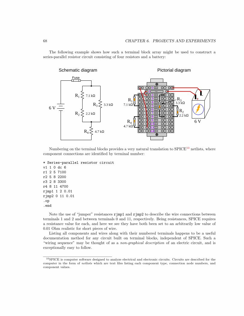
68 CHAPTER 6. PROJECTS AND EXPERIMENTS
The following example shows how such a terminal block array might be used to construct aseries-parallel resistor circuit consisting of four resistors and a battery:
Fuse1
54
678910
0
2
1112
3 +-
Pictorial diagramSchematic diagram
R1
R2
R3
R4
Fuse
R1
R2
R3
R4
6 V
6 V
2.2 kΩ
3.3 kΩ
4.7 kΩ
7.1 kΩ
7.1 kΩ
2.2 kΩ
3.3 kΩ
4.7 kΩ
Numbering on the terminal blocks provides a very natural translation to SPICE10 netlists, wherecomponent connections are identified by terminal number:
* Series-parallel resistor circuit
v1 1 0 dc 6
r1 2 5 7100
r2 5 8 2200
r3 2 8 3300
r4 8 11 4700
rjmp1 1 2 0.01
rjmp2 0 11 0.01
.op
.end
Note the use of “jumper” resistances rjmp1 and rjmp2 to describe the wire connections betweenterminals 1 and 2 and between terminals 0 and 11, respectively. Being resistances, SPICE requiresa resistance value for each, and here we see they have both been set to an arbitrarily low value of0.01 Ohm realistic for short pieces of wire.
Listing all components and wires along with their numbered terminals happens to be a usefuldocumentation method for any circuit built on terminal blocks, independent of SPICE. Such a“wiring sequence” may be thought of as a non-graphical description of an electric circuit, and isexceptionally easy to follow.
10SPICE is computer software designed to analyze electrical and electronic circuits. Circuits are described for thecomputer in the form of netlists which are text files listing each component type, connection node numbers, andcomponent values.

6.1. RECOMMENDED PRACTICES 69
An example of a more elaborate terminal block array is shown in the following photograph,with terminal blocks and “ice-cube” style electromechanical relays mounted to DIN rail, which isturn mounted to a perforated subpanel11. This “terminal block board” hosts an array of thirty fiveundedicated terminal block sections, four SPDT toggle switches, four DPDT “ice-cube” relays, astep-down control power transformer, bridge rectifier and filtering capacitor, and several fuses forovercurrent protection:
Four plastic-bottomed “feet” support the subpanel above the benchtop surface, and an unusedsection of DIN rail stands ready to accept other components. Safety features include electricalbonding of the AC line power cord’s ground to the metal subpanel (and all metal DIN rails),mechanical strain relief for the power cord to isolate any cord tension from wire connections,clear plastic finger guards covering the transformer’s screw terminals, as well as fused overcurrentprotection for the 120 Volt AC line power and the transformer’s 12 Volt AC output. The perforatedholes happen to be on 1
4inch centers, their presence making it very easy to attach other sections
of DIN rail, or specialized electrical components, directly to the grounded metal subpanel. Such a“terminal block board” is an inexpensive12 yet highly flexible means to construct physically robustcircuits using industrial wiring practices.
11An electrical subpanel is a thin metal plate intended for mounting inside an electrical enclosure. Components areattached to the subpanel, and the subpanel in turn bolts inside the enclosure. Subpanels allow circuit constructionoutside the confines of the enclosure, which speeds assembly. In this particular usage there is no enclosure, as thesubpanel is intended to be used as an open platform for the convenient construction of circuits on a benchtop bystudents. In essence, this is a modern version of the traditional breadboard which was literally a wooden board suchas might be used for cutting loaves of bread, but which early electrical and electronic hobbyists used as platforms forthe construction of circuits.
12At the time of this writing (2019) the cost to build this board is approximately $250 US dollars.

70 CHAPTER 6. PROJECTS AND EXPERIMENTS
6.1.4 Conducting experiments
An experiment is an exploratory act, a test performed for the purpose of assessing some propositionor principle. Experiments are the foundation of the scientific method, a process by which carefulobservation helps guard against errors of speculation. All good experiments begin with an hypothesis,defined by the American Heritage Dictionary of the English Language as:
An assertion subject to verification or proof, as (a) A proposition stated as a basis forargument or reasoning. (b) A premise from which a conclusion is drawn. (c) A conjecturethat accounts, within a theory or ideational framework, for a set of facts and that canbe used as a basis for further investigation.
Stated plainly, an hypothesis is an educated guess about cause and effect. The correctness of thisinitial guess matters little, because any well-designed experiment will reveal the truth of the matter.In fact, incorrect hypotheses are often the most valuable because the experiments they engenderlead us to surprising discoveries. One of the beautiful aspects of science is that it is more focusedon the process of learning than about the status of being correct13. In order for an hypothesis to bevalid, it must be testable14, which means it must be a claim possible to refute given the right data.Hypotheses impossible to critique are useless.
Once an hypothesis has been formulated, an experiment must be designed to test that hypothesis.A well-designed experiment requires careful regulation of all relevant variables, both for personalsafety and for prompting the hypothesized results. If the effects of one particular variable are tobe tested, the experiment must be run multiple times with different values of (only) that particularvariable. The experiment set up with the “baseline” variable set is called the control, while theexperiment set up with different value(s) is called the test or experimental.
For some hypotheses a viable alternative to a physical experiment is a computer-simulated
experiment or even a thought experiment. Simulations performed on a computer test the hypothesisagainst the physical laws encoded within the computer simulation software, and are particularlyuseful for students learning new principles for which simulation software is readily available15.
13Science is more about clarifying our view of the universe through a systematic process of error detection than it isabout proving oneself to be right. Some scientists may happen to have large egos – and this may have more to do withthe ways in which large-scale scientific research is funded than anything else – but scientific method itself is devoidof ego, and if embraced as a practical philosophy is quite an effective stimulant for humility. Within the educationsystem, scientific method is particularly valuable for helping students break free of the crippling fear of being wrong.So much emphasis is placed in formal education on assessing correct retention of facts that many students are fearfulof saying or doing anything that might be perceived as a mistake, and of course making mistakes (i.e. having one’shypotheses disproven by experiment) is an indispensable tool for learning. Introducing science in the classroom – real
science characterized by individuals forming actual hypotheses and testing those hypotheses by experiment – helpsstudents become self-directed learners.
14This is the principle of falsifiability: that a scientific statement has value only insofar as it is liable to disproofgiven the requisite experimental evidence. Any claim that is unfalsifiable – that is, a claim which can never bedisproven by any evidence whatsoever – could be completely wrong and we could never know it.
15A very pertinent example of this is learning how to analyze electric circuits using simulation software such asSPICE. A typical experimental cycle would proceed as follows: (1) Find or invent a circuit to analyze; (2) Applyyour analytical knowledge to that circuit, predicting all voltages, currents, powers, etc. relevant to the concepts youare striving to master; (3) Run a simulation on that circuit, collecting “data” from the computer when complete; (4)Evaluate whether or not your hypotheses (i.e. predicted voltages, currents, etc.) agree with the computer-generatedresults; (5) If so, your analyses are (provisionally) correct – if not, examine your analyses and the computer simulationagain to determine the source of error; (6) Repeat this process as many times as necessary until you achieve mastery.

6.1. RECOMMENDED PRACTICES 71
Thought experiments are useful for detecting inconsistencies within your own understanding ofsome subject, rather than testing your understanding against physical reality.
Here are some general guidelines for conducting experiments:
• The clearer and more specific the hypothesis, the better. Vague or unfalsifiable hypothesesare useless because they will fit any experimental results, and therefore the experiment cannotteach you anything about the hypothesis.
• Collect as much data (i.e. information, measurements, sensory experiences) generated by anexperiment as is practical. This includes the time and date of the experiment, too!
• Never discard or modify data gathered from an experiment. If you have reason to believe thedata is unreliable, write notes to that effect, but never throw away data just because you thinkit is untrustworthy. It is quite possible that even “bad” data holds useful information, andthat someone else may be able to uncover its value even if you do not.
• Prioritize quantitative data over qualitative data wherever practical. Quantitative data is morespecific than qualitative, less prone to subjective interpretation on the part of the experimenter,and amenable to an arsenal of analytical methods (e.g. statistics).
• Guard against your own bias(es) by making your experimental results available to others. Thisallows other people to scrutinize your experimental design and collected data, for the purposeof detecting and correcting errors you may have missed. Document your experiment such thatothers may independently replicate it.
• Always be looking for sources of error. No physical measurement is perfect, and so it isimpossible to achieve exact values for any variable. Quantify the amount of uncertainty (i.e.the “tolerance” of errors) whenever possible, and be sure your hypothesis does not depend onprecision better than this!
• Always remember that scientific confirmation is provisional – no number of “successful”experiments will prove an hypothesis true for all time, but a single experiment can disproveit. Put into simpler terms, truth is elusive but error is within reach.
• Remember that scientific method is about learning, first and foremost. An unfortunateconsequence of scientific triumph in modern society is that science is often viewed by non-practitioners as an unerring source of truth, when in fact science is an ongoing process ofchallenging existing ideas to probe for errors and oversights. This is why it is perfectlyacceptable to have a failed hypothesis, and why the only truly failed experiment is one wherenothing was learned.

72 CHAPTER 6. PROJECTS AND EXPERIMENTS
The following is an example of a well-planned and executed experiment, in this case a physicalexperiment demonstrating Ohm’s Law.
Planning Time/Date = 09:30 on 12 February 2019
HYPOTHESIS: the current through any resistor should be exactly proportional
to the voltage impressed across it.
PROCEDURE: connect a resistor rated 1 k Ohm and 1/4 Watt to a variable-voltage
DC power supply. Use an ammeter in series to measure resistor current and
a voltmeter in parallel to measure resistor voltage.
RISKS AND MITIGATION: excessive power dissipation may harm the resistor and/
or pose a burn hazard, while excessive voltage poses an electric shock hazard.
30 Volts is a safe maximum voltage for laboratory practices, and according to
Joule’s Law a 1000 Ohm resistor will dissipate 0.25 Watts at 15.81 Volts
(P = V^2 / R), so I will remain below 15 Volts just to be safe.
Experiment Time/Date = 10:15 on 12 February 2019
DATA COLLECTED:
(Voltage) (Current) (Voltage) (Current)
0.000 V = 0.000 mA 8.100 = 7.812 mA
2.700 V = 2.603 mA 10.00 V = 9.643 mA
5.400 V = 5.206 mA 14.00 V = 13.49 mA
Analysis Time/Date = 10:57 on 12 February 2019
ANALYSIS: current definitely increases with voltage, and although I expected
exactly one milliAmpere per Volt the actual current was usually less than
that. The voltage/current ratios ranged from a low of 1036.87 (at 8.1 Volts)
to a high of 1037.81 (at 14 Volts), but this represents a variance of only
-0.0365% to +0.0541% from the average, indicating a very consistent
proportionality -- results consistent with Ohm’s Law.
ERROR SOURCES: one major source of error is the resistor’s value itself. I
did not measure it, but simply assumed color bands of brown-black-red meant
exactly 1000 Ohms. Based on the data I think the true resistance is closer
to 1037 Ohms. Another possible explanation is multimeter calibration error.
However, neither explains the small positive and negative variances from the
average. This might be due to electrical noise, a good test being to repeat
the same experiment to see if the variances are the same or different. Noise
should generate slightly different results every time.

6.1. RECOMMENDED PRACTICES 73
The following is an example of a well-planned and executed virtual experiment, in this casedemonstrating Ohm’s Law using a computer (SPICE) simulation.
Planning Time/Date = 12:32 on 14 February 2019
HYPOTHESIS: for any given resistor, the current through that resistor should be
exactly proportional to the voltage impressed across it.
PROCEDURE: write a SPICE netlist with a single DC voltage source and single
1000 Ohm resistor, then use NGSPICE version 26 to perform a "sweep" analysis
from 0 Volts to 25 Volts in 5 Volt increments.
* SPICE circuit
v1 1 0 dc
r1 1 0 1000
.dc v1 0 25 5
.print dc v(1) i(v1)
.end
RISKS AND MITIGATION: none.
DATA COLLECTED:
DC transfer characteristic Thu Feb 14 13:05:08 2019
-----------------------------------------------------------
Index v-sweep v(1) v1#branch
-----------------------------------------------------------
0 0.000000e+00 0.000000e+00 0.000000e+00
1 5.000000e+00 5.000000e+00 -5.00000e-03
2 1.000000e+01 1.000000e+01 -1.00000e-02
3 1.500000e+01 1.500000e+01 -1.50000e-02
4 2.000000e+01 2.000000e+01 -2.00000e-02
5 2.500000e+01 2.500000e+01 -2.50000e-02
Analysis Time/Date = 13:06 on 14 February 2019
ANALYSIS: perfect agreement between data and hypothesis -- current is precisely
1/1000 of the applied voltage for all values. Anything other than perfect
agreement would have probably meant my netlist was incorrect. The negative
current values surprised me, but it seems this is just how SPICE interprets
normal current through a DC voltage source.
ERROR SOURCES: none.

74 CHAPTER 6. PROJECTS AND EXPERIMENTS
As gratuitous as it may seem to perform experiments on a physical law as well-established asOhm’s Law, even the examples listed previously demonstrate opportunity for real learning. Inthe physical experiment example, the student should identify and explain why their data does notperfectly agree with the hypothesis, and this leads them naturally to consider sources of error. Inthe computer-simulated experiment, the student is struck by SPICE’s convention of denoting regularcurrent through a DC voltage source as being negative in sign, and this is also useful knowledge forfuture simulations. Scientific experiments are most interesting when things do not go as planned!
Aside from verifying well-established physical laws, simple experiments are extremely useful aseducational tools for a wide range of purposes, including:
• Component familiarization (e.g. Which terminals of this switch connect to the NO versus NC
contacts? )
• System testing (e.g. How heavy of a load can my AC-DC power supply source before the
semiconductor components reach their thermal limits? )
• Learning programming languages (e.g. Let’s try to set up an “up” counter function in this
PLC! )
Above all, the priority here is to inculcate the habit of hypothesizing, running experiments, andanalyzing the results. This experimental cycle not only serves as an excellent method for self-directedlearning, but it also works exceptionally well for troubleshooting faults in complex systems, and forthese reasons should be a part of every technician’s and every engineer’s education.
6.1.5 Constructing projects
Designing, constructing, and testing projects is a very effective means of practical education. Withina formal educational setting, projects are generally chosen (or at least vetted) by an instructorto ensure they may be reasonably completed within the allotted time of a course or program ofstudy, and that they sufficiently challenge the student to learn certain important principles. In aself-directed environment, projects are just as useful as a learning tool but there is some risk ofunwittingly choosing a project beyond one’s abilities, which can lead to frustration.
Here are some general guidelines for managing projects:
• Define your goal(s) before beginning a project: what do you wish to achieve in building it?What, exactly, should the completed project do?
• Analyze your project prior to construction. Document it in appropriate forms (e.g. schematicdiagrams), predict its functionality, anticipate all associated risks. In other words, plan ahead.
• Set a reasonable budget for your project, and stay within it.
• Identify any deadlines, and set reasonable goals to meet those deadlines.
• Beware of scope creep: the tendency to modify the project’s goals before it is complete.
• Document your progress! An easy way to do this is to use photography or videography: takephotos and/or videos of your project as it progresses. Document failures as well as successes,because both are equally valuable from the perspective of learning.

6.2. EXPERIMENT: (FIRST EXPERIMENT) 75
6.2 Experiment: (first experiment)
The purpose of this experiment is to . . .You will need the following components and materials for this experiment . . .
•
•
•
First and foremost, identify any potential hazards posed by this experiment. If any exist, identifyhow to mitigate each of those risks to ensure personal safety as well as ensure no components orequipment will be damaged.
Formulate an hypothesis (i.e. an educated guess) as to . . .
Design your experiment in such a way as to clearly test your hypothesis. What evidence wouldagree with your hypothesis? What evidence would disprove your hypothesis? What type andquantity of data must you collect in order to have sufficient evidence?
One of the essential requirements of any scientific test is that it be controlled to guard againstfalse conclusions. This means running multiple instances16 of the experiment in order to gathercomparative data.
Be sure to document all data in a neat and well-organized format, easily understood
by anyone viewing it. Be prepared to explain your reasoning at every step, and also to
demonstrate the safe and proper use of all materials, components, and equipment. If
a live demonstration is not practical, record your actions on video.
Challenges
• ???.
• ???.
• ???.
16For example, if we were trying to determine the effect of light exposure on plant growth, we would need to growmultiple plants under different light conditions while maintaining all other conditions (e.g. temperature, humidity,soil type, etc.) equal. In experiments where the hypothesis is very narrowly defined, we would need to compare theresults of the hypothesized condition (“test”) against a lack of the hypothesized condition (“control”). For example,if our hypothesis was that bean sprouts grow best when watered with the athletic beverage Gatorade, we wouldneed to grow several bean sprouts under different conditions: some irrigated with plain water and others irrigatedwith Gatorade. The plain-water sprouts would constitute our “control” group while the Gatorade-irrigated sproutswould constitute our “test” group. The hypothesis of enhanced growth under Gatorade could only be confirmed, andprovisionally at that, if a majority of the test sprouts grew better than a majority of the control sprouts.

76 CHAPTER 6. PROJECTS AND EXPERIMENTS
6.3 Project: (first project)
This is a description of the project!
Challenges
• ???.
• ???.
• ???.

Appendix A
Problem-Solving Strategies
The ability to solve complex problems is arguably one of the most valuable skills one can possess,and this skill is particularly important in any science-based discipline.
• Study principles, not procedures. Don’t be satisfied with merely knowing how to computesolutions – learn why those solutions work.
• Identify what it is you need to solve, identify all relevant data, identify all units of measurement,identify any general principles or formulae linking the given information to the solution, andthen identify any “missing pieces” to a solution. Annotate all diagrams with this data.
• Sketch a diagram to help visualize the problem. When building a real system, always devisea plan for that system and analyze its function before constructing it.
• Follow the units of measurement and meaning of every calculation. If you are ever performingmathematical calculations as part of a problem-solving procedure, and you find yourself unableto apply each and every intermediate result to some aspect of the problem, it means youdon’t understand what you are doing. Properly done, every mathematical result should havepractical meaning for the problem, and not just be an abstract number. You should be able toidentify the proper units of measurement for each and every calculated result, and show wherethat result fits into the problem.
• Perform “thought experiments” to explore the effects of different conditions for theoreticalproblems. When troubleshooting real systems, perform diagnostic tests rather than visuallyinspecting for faults, the best diagnostic test being the one giving you the most informationabout the nature and/or location of the fault with the fewest steps.
• Simplify the problem until the solution becomes obvious, and then use that obvious case as amodel to follow in solving the more complex version of the problem.
• Check for exceptions to see if your solution is incorrect or incomplete. A good solution willwork for all known conditions and criteria. A good example of this is the process of testingscientific hypotheses: the task of a scientist is not to find support for a new idea, but ratherto challenge that new idea to see if it holds up under a battery of tests. The philosophical
77

78 APPENDIX A. PROBLEM-SOLVING STRATEGIES
principle of reductio ad absurdum (i.e. disproving a general idea by finding a specific casewhere it fails) is useful here.
• Work “backward” from a hypothetical solution to a new set of given conditions.
• Add quantities to problems that are qualitative in nature, because sometimes a little mathhelps illuminate the scenario.
• Sketch graphs illustrating how variables relate to each other. These may be quantitative (i.e.with realistic number values) or qualitative (i.e. simply showing increases and decreases).
• Treat quantitative problems as qualitative in order to discern the relative magnitudes and/ordirections of change of the relevant variables. For example, try determining what happens if acertain variable were to increase or decrease before attempting to precisely calculate quantities:how will each of the dependent variables respond, by increasing, decreasing, or remaining thesame as before?
• Consider limiting cases. This works especially well for qualitative problems where you need todetermine which direction a variable will change. Take the given condition and magnify thatcondition to an extreme degree as a way of simplifying the direction of the system’s response.
• Check your work. This means regularly testing your conclusions to see if they make sense.This does not mean repeating the same steps originally used to obtain the conclusion(s), butrather to use some other means to check validity. Simply repeating procedures often leads torepeating the same errors if any were made, which is why alternative paths are better.

Appendix B
Instructional philosophy
“The unexamined circuit is not worth energizing” – Socrates (if he had taught electricity)
These learning modules, although useful for self-study, were designed to be used in a formallearning environment where a subject-matter expert challenges students to digest the content andexercise their critical thinking abilities in the answering of questions and in the construction andtesting of working circuits.
The following principles inform the instructional and assessment philosophies embodied in theselearning modules:
• The first goal of education is to enhance clear and independent thought, in order thatevery student reach their fullest potential in a highly complex and inter-dependent world.Robust reasoning is always more important than particulars of any subject matter, becauseits application is universal.
• Literacy is fundamental to independent learning and thought because text continues to be themost efficient way to communicate complex ideas over space and time. Those who cannot readwith ease are limited in their ability to acquire knowledge and perspective.
• Articulate communication is fundamental to work that is complex and interdisciplinary.
• Faulty assumptions and poor reasoning are best corrected through challenge, not presentation.The rhetorical technique of reductio ad absurdum (disproving an assertion by exposing anabsurdity) works well to discipline student’s minds, not only to correct the problem at handbut also to learn how to detect and correct future errors.
• Important principles should be repeatedly explored and widely applied throughout a courseof study, not only to reinforce their importance and help ensure their mastery, but also toshowcase the interconnectedness and utility of knowledge.
79

80 APPENDIX B. INSTRUCTIONAL PHILOSOPHY
These learning modules were expressly designed to be used in an “inverted” teachingenvironment1 where students first read the introductory and tutorial chapters on their own, thenindividually attempt to answer the questions and construct working circuits according to theexperiment and project guidelines. The instructor never lectures, but instead meets regularlywith each individual student to review their progress, answer questions, identify misconceptions,and challenge the student to new depths of understanding through further questioning. Regularmeetings between instructor and student should resemble a Socratic2 dialogue, where questionsserve as scalpels to dissect topics and expose assumptions. The student passes each module onlyafter consistently demonstrating their ability to logically analyze and correctly apply all majorconcepts in each question or project/experiment. The instructor must be vigilant in probing eachstudent’s understanding to ensure they are truly reasoning and not just memorizing. This is why“Challenge” points appear throughout, as prompts for students to think deeper about topics and asstarting points for instructor queries. Sometimes these challenge points require additional knowledgethat hasn’t been covered in the series to answer in full. This is okay, as the major purpose of theChallenges is to stimulate analysis and synthesis on the part of each student.
The instructor must possess enough mastery of the subject matter and awareness of students’reasoning to generate their own follow-up questions to practically any student response. Evencompletely correct answers given by the student should be challenged by the instructor for thepurpose of having students practice articulating their thoughts and defending their reasoning.Conceptual errors committed by the student should be exposed and corrected not by directinstruction, but rather by reducing the errors to an absurdity3 through well-chosen questions andthought experiments posed by the instructor. Becoming proficient at this style of instruction requirestime and dedication, but the positive effects on critical thinking for both student and instructor arespectacular.
An inspection of these learning modules reveals certain unique characteristics. One of these isa bias toward thorough explanations in the tutorial chapters. Without a live instructor to explainconcepts and applications to students, the text itself must fulfill this role. This philosophy results inlengthier explanations than what you might typically find in a textbook, each step of the reasoningprocess fully explained, including footnotes addressing common questions and concerns studentsraise while learning these concepts. Each tutorial seeks to not only explain each major conceptin sufficient detail, but also to explain the logic of each concept and how each may be developed
1In a traditional teaching environment, students first encounter new information via lecture from an expert, andthen independently apply that information via homework. In an “inverted” course of study, students first encounternew information via homework, and then independently apply that information under the scrutiny of an expert. Theexpert’s role in lecture is to simply explain, but the expert’s role in an inverted session is to challenge, critique, andif necessary explain where gaps in understanding still exist.
2Socrates is a figure in ancient Greek philosophy famous for his unflinching style of questioning. Although heauthored no texts, he appears as a character in Plato’s many writings. The essence of Socratic philosophy is toleave no question unexamined and no point of view unchallenged. While purists may argue a topic such as electriccircuits is too narrow for a true Socratic-style dialogue, I would argue that the essential thought processes involvedwith scientific reasoning on any topic are not far removed from the Socratic ideal, and that students of electricity andelectronics would do very well to challenge assumptions, pose thought experiments, identify fallacies, and otherwiseemploy the arsenal of critical thinking skills modeled by Socrates.
3This rhetorical technique is known by the Latin phrase reductio ad absurdum. The concept is to expose errors bycounter-example, since only one solid counter-example is necessary to disprove a universal claim. As an example ofthis, consider the common misconception among beginning students of electricity that voltage cannot exist withoutcurrent. One way to apply reductio ad absurdum to this statement is to ask how much current passes through afully-charged battery connected to nothing (i.e. a clear example of voltage existing without current).

81
from “first principles”. Again, this reflects the goal of developing clear and independent thought instudents’ minds, by showing how clear and logical thought was used to forge each concept. Studentsbenefit from witnessing a model of clear thinking in action, and these tutorials strive to be just that.
Another characteristic of these learning modules is a lack of step-by-step instructions in theProject and Experiment chapters. Unlike many modern workbooks and laboratory guides wherestep-by-step instructions are prescribed for each experiment, these modules take the approach thatstudents must learn to closely read the tutorials and apply their own reasoning to identify theappropriate experimental steps. Sometimes these steps are plainly declared in the text, just not asa set of enumerated points. At other times certain steps are implied, an example being assumedcompetence in test equipment use where the student should not need to be told again how to usetheir multimeter because that was thoroughly explained in previous lessons. In some circumstancesno steps are given at all, leaving the entire procedure up to the student.
This lack of prescription is not a flaw, but rather a feature. Close reading and clear thinking arefoundational principles of this learning series, and in keeping with this philosophy all activities aredesigned to require those behaviors. Some students may find the lack of prescription frustrating,because it demands more from them than what their previous educational experiences required. Thisfrustration should be interpreted as an unfamiliarity with autonomous thinking, a problem whichmust be corrected if the student is ever to become a self-directed learner and effective problem-solver.Ultimately, the need for students to read closely and think clearly is more important both in thenear-term and far-term than any specific facet of the subject matter at hand. If a student takeslonger than expected to complete a module because they are forced to outline, digest, and reasonon their own, so be it. The future gains enjoyed by developing this mental discipline will be wellworth the additional effort and delay.
Another feature of these learning modules is that they do not treat topics in isolation. Rather,important concepts are introduced early in the series, and appear repeatedly as stepping-stonestoward other concepts in subsequent modules. This helps to avoid the “compartmentalization”of knowledge, demonstrating the inter-connectedness of concepts and simultaneously reinforcingthem. Each module is fairly complete in itself, reserving the beginning of its tutorial to a review offoundational concepts.
This methodology of assigning text-based modules to students for digestion and then usingSocratic dialogue to assess progress and hone students’ thinking was developed over a period ofseveral years by the author with his Electronics and Instrumentation students at the two-year collegelevel. While decidedly unconventional and sometimes even unsettling for students accustomed toa more passive lecture environment, this instructional philosophy has proven its ability to conveyconceptual mastery, foster careful analysis, and enhance employability so much better than lecturethat the author refuses to ever teach by lecture again.
Problems which often go undiagnosed in a lecture environment are laid bare in this “inverted”format where students must articulate and logically defend their reasoning. This, too, may beunsettling for students accustomed to lecture sessions where the instructor cannot tell for sure whocomprehends and who does not, and this vulnerability necessitates sensitivity on the part of the“inverted” session instructor in order that students never feel discouraged by having their errorsexposed. Everyone makes mistakes from time to time, and learning is a lifelong process! Part ofthe instructor’s job is to build a culture of learning among the students where errors are not seen asshameful, but rather as opportunities for progress.

82 APPENDIX B. INSTRUCTIONAL PHILOSOPHY
To this end, instructors managing courses based on these modules should adhere to the followingprinciples:
• Student questions are always welcome and demand thorough, honest answers. The only typeof question an instructor should refuse to answer is one the student should be able to easilyanswer on their own. Remember, the fundamental goal of education is for each student to learn
to think clearly and independently. This requires hard work on the part of the student, whichno instructor should ever circumvent. Anything done to bypass the student’s responsibility todo that hard work ultimately limits that student’s potential and thereby does real harm.
• It is not only permissible, but encouraged, to answer a student’s question by asking questionsin return, these follow-up questions designed to guide the student to reach a correct answerthrough their own reasoning.
• All student answers demand to be challenged by the instructor and/or by other students.This includes both correct and incorrect answers – the goal is to practice the articulation anddefense of one’s own reasoning.
• No reading assignment is deemed complete unless and until the student demonstrates theirability to accurately summarize the major points in their own terms. Recitation of the originaltext is unacceptable. This is why every module contains an “Outline and reflections” questionas well as a “Foundational concepts” question in the Conceptual reasoning section, to promptreflective reading.
• No assigned question is deemed answered unless and until the student demonstrates theirability to consistently and correctly apply the concepts to variations of that question. This iswhy module questions typically contain multiple “Challenges” suggesting different applicationsof the concept(s) as well as variations on the same theme(s). Instructors are encouraged todevise as many of their own “Challenges” as they are able, in order to have a multitude ofways ready to probe students’ understanding.
• No assigned experiment or project is deemed complete unless and until the studentdemonstrates the task in action. If this cannot be done “live” before the instructor, video-recordings showing the demonstration are acceptable. All relevant safety precautions must befollowed, all test equipment must be used correctly, and the student must be able to properlyexplain all results. The student must also successfully answer all Challenges presented by theinstructor for that experiment or project.

83
Students learning from these modules would do well to abide by the following principles:
• No text should be considered fully and adequately read unless and until you can express everyidea in your own words, using your own examples.
• You should always articulate your thoughts as you read the text, noting points of agreement,confusion, and epiphanies. Feel free to print the text on paper and then write your notes inthe margins. Alternatively, keep a journal for your own reflections as you read. This is trulya helpful tool when digesting complicated concepts.
• Never take the easy path of highlighting or underlining important text. Instead, summarize
and/or comment on the text using your own words. This actively engages your mind, allowingyou to more clearly perceive points of confusion or misunderstanding on your own.
• A very helpful strategy when learning new concepts is to place yourself in the role of a teacher,if only as a mental exercise. Either explain what you have recently learned to someone else,or at least imagine yourself explaining what you have learned to someone else. The simple actof having to articulate new knowledge and skill forces you to take on a different perspective,and will help reveal weaknesses in your understanding.
• Perform each and every mathematical calculation and thought experiment shown in the texton your own, referring back to the text to see that your results agree. This may seem trivialand unnecessary, but it is critically important to ensuring you actually understand what ispresented, especially when the concepts at hand are complicated and easy to misunderstand.Apply this same strategy to become proficient in the use of circuit simulation software, checkingto see if your simulated results agree with the results shown in the text.
• Above all, recognize that learning is hard work, and that a certain level of frustration isunavoidable. There are times when you will struggle to grasp some of these concepts, and thatstruggle is a natural thing. Take heart that it will yield with persistent and varied4 effort, andnever give up!
Students interested in using these modules for self-study will also find them beneficial, althoughthe onus of responsibility for thoroughly reading and answering questions will of course lie withthat individual alone. If a qualified instructor is not available to challenge students, a workablealternative is for students to form study groups where they challenge5 one another.
To high standards of education,
Tony R. Kuphaldt
4As the old saying goes, “Insanity is trying the same thing over and over again, expecting different results.” Ifyou find yourself stumped by something in the text, you should attempt a different approach. Alter the thoughtexperiment, change the mathematical parameters, do whatever you can to see the problem in a slightly different light,and then the solution will often present itself more readily.
5Avoid the temptation to simply share answers with study partners, as this is really counter-productive to learning.Always bear in mind that the answer to any question is far less important in the long run than the method(s) used toobtain that answer. The goal of education is to empower one’s life through the improvement of clear and independentthought, literacy, expression, and various practical skills.

84 APPENDIX B. INSTRUCTIONAL PHILOSOPHY

Appendix C
Tools used
I am indebted to the developers of many open-source software applications in the creation of theselearning modules. The following is a list of these applications with some commentary on each.
You will notice a theme common to many of these applications: a bias toward code. AlthoughI am by no means an expert programmer in any computer language, I understand and appreciatethe flexibility offered by code-based applications where the user (you) enters commands into a plainASCII text file, which the software then reads and processes to create the final output. Code-basedcomputer applications are by their very nature extensible, while WYSIWYG (What You See Is WhatYou Get) applications are generally limited to whatever user interface the developer makes for you.
The GNU/Linux computer operating system
There is so much to be said about Linus Torvalds’ Linux and Richard Stallman’s GNU
project. First, to credit just these two individuals is to fail to do justice to the mob ofpassionate volunteers who contributed to make this amazing software a reality. I firstlearned of Linux back in 1996, and have been using this operating system on my personalcomputers almost exclusively since then. It is free, it is completely configurable, and itpermits the continued use of highly efficient Unix applications and scripting languages(e.g. shell scripts, Makefiles, sed, awk) developed over many decades. Linux not onlyprovided me with a powerful computing platform, but its open design served to inspiremy life’s work of creating open-source educational resources.
Bram Moolenaar’s Vim text editor
Writing code for any code-based computer application requires a text editor, which maybe thought of as a word processor strictly limited to outputting plain-ASCII text files.Many good text editors exist, and one’s choice of text editor seems to be a deeply personalmatter within the programming world. I prefer Vim because it operates very similarly tovi which is ubiquitous on Unix/Linux operating systems, and because it may be entirelyoperated via keyboard (i.e. no mouse required) which makes it fast to use.
85

86 APPENDIX C. TOOLS USED
Donald Knuth’s TEX typesetting system
Developed in the late 1970’s and early 1980’s by computer scientist extraordinaire DonaldKnuth to typeset his multi-volume magnum opus The Art of Computer Programming,this software allows the production of formatted text for screen-viewing or paper printing,all by writing plain-text code to describe how the formatted text is supposed to appear.TEX is not just a markup language for documents, but it is also a Turing-completeprogramming language in and of itself, allowing useful algorithms to be created to controlthe production of documents. Simply put, TEX is a programmer’s approach to word
processing. Since TEX is controlled by code written in a plain-text file, this meansanyone may read that plain-text file to see exactly how the document was created. Thisopenness afforded by the code-based nature of TEX makes it relatively easy to learn howother people have created their own TEX documents. By contrast, examining a beautifuldocument created in a conventional WYSIWYG word processor such as Microsoft Wordsuggests nothing to the reader about how that document was created, or what the usermight do to create something similar. As Mr. Knuth himself once quipped, conventionalword processing applications should be called WYSIAYG (What You See Is All YouGet).
Leslie Lamport’s LATEX extensions to TEX
Like all true programming languages, TEX is inherently extensible. So, years after therelease of TEX to the public, Leslie Lamport decided to create a massive extensionallowing easier compilation of book-length documents. The result was LATEX, whichis the markup language used to create all ModEL module documents. You could saythat TEX is to LATEX as C is to C++. This means it is permissible to use any and all TEXcommands within LATEX source code, and it all still works. Some of the features offeredby LATEX that would be challenging to implement in TEX include automatic index andtable-of-content creation.
Tim Edwards’ Xcircuit drafting program
This wonderful program is what I use to create all the schematic diagrams andillustrations (but not photographic images or mathematical plots) throughout the ModELproject. It natively outputs PostScript format which is a true vector graphic format (thisis why the images do not pixellate when you zoom in for a closer view), and it is so simpleto use that I have never had to read the manual! Object libraries are easy to create forXcircuit, being plain-text files using PostScript programming conventions. Over theyears I have collected a large set of object libraries useful for drawing electrical andelectronic schematics, pictorial diagrams, and other technical illustrations.

87
Gimp graphic image manipulation program
Essentially an open-source clone of Adobe’s PhotoShop, I use Gimp to resize, crop, andconvert file formats for all of the photographic images appearing in the ModEL modules.Although Gimp does offer its own scripting language (called Script-Fu), I have neverhad occasion to use it. Thus, my utilization of Gimp to merely crop, resize, and convertgraphic images is akin to using a sword to slice a loaf of bread.
SPICE circuit simulation program
SPICE is to circuit analysis as TEX is to document creation: it is a form of markuplanguage designed to describe a certain object to be processed in plain-ASCII text.When the plain-text “source file” is compiled by the software, it outputs the final result.More modern circuit analysis tools certainly exist, but I prefer SPICE for the followingreasons: it is free, it is fast, it is reliable, and it is a fantastic tool for teaching students ofelectricity and electronics how to write simple code. I happen to use rather old versions ofSPICE, version 2g6 being my “go to” application when I only require text-based output.NGSPICE (version 26), which is based on Berkeley SPICE version 3f5, is used when Irequire graphical output for such things as time-domain waveforms and Bode plots. Inall SPICE example netlists I strive to use coding conventions compatible with all SPICEversions.
Andrew D. Hwang’s ePiX mathematical visualization programming library
This amazing project is a C++ library you may link to any C/C++ code for the purposeof generating PostScript graphic images of mathematical functions. As a completelyfree and open-source project, it does all the plotting I would otherwise use a ComputerAlgebra System (CAS) such as Mathematica or Maple to do. It should be said thatePiX is not a Computer Algebra System like Mathematica or Maple, but merely amathematical visualization tool. In other words, it won’t determine integrals for you(you’ll have to implement that in your own C/C++ code!), but it can graph the results, andit does so beautifully. What I really admire about ePiX is that it is a C++ programminglibrary, which means it builds on the existing power and toolset available with thatprogramming language. Mr. Hwang could have probably developed his own stand-aloneapplication for mathematical plotting, but by creating a C++ library to do the same thinghe accomplished something much greater.

88 APPENDIX C. TOOLS USED

Appendix D
Creative Commons License
Creative Commons Attribution 4.0 International Public License
By exercising the Licensed Rights (defined below), You accept and agree to be bound by the termsand conditions of this Creative Commons Attribution 4.0 International Public License (“PublicLicense”). To the extent this Public License may be interpreted as a contract, You are granted theLicensed Rights in consideration of Your acceptance of these terms and conditions, and the Licensorgrants You such rights in consideration of benefits the Licensor receives from making the LicensedMaterial available under these terms and conditions.
Section 1 – Definitions.
a. Adapted Material means material subject to Copyright and Similar Rights that is derivedfrom or based upon the Licensed Material and in which the Licensed Material is translated, altered,arranged, transformed, or otherwise modified in a manner requiring permission under the Copyrightand Similar Rights held by the Licensor. For purposes of this Public License, where the LicensedMaterial is a musical work, performance, or sound recording, Adapted Material is always producedwhere the Licensed Material is synched in timed relation with a moving image.
b. Adapter’s License means the license You apply to Your Copyright and Similar Rights inYour contributions to Adapted Material in accordance with the terms and conditions of this PublicLicense.
c. Copyright and Similar Rights means copyright and/or similar rights closely related tocopyright including, without limitation, performance, broadcast, sound recording, and Sui GenerisDatabase Rights, without regard to how the rights are labeled or categorized. For purposes of thisPublic License, the rights specified in Section 2(b)(1)-(2) are not Copyright and Similar Rights.
d. Effective Technological Measures means those measures that, in the absence of properauthority, may not be circumvented under laws fulfilling obligations under Article 11 of the WIPOCopyright Treaty adopted on December 20, 1996, and/or similar international agreements.
e. Exceptions and Limitations means fair use, fair dealing, and/or any other exception or
89

90 APPENDIX D. CREATIVE COMMONS LICENSE
limitation to Copyright and Similar Rights that applies to Your use of the Licensed Material.
f. Licensed Material means the artistic or literary work, database, or other material to whichthe Licensor applied this Public License.
g. Licensed Rights means the rights granted to You subject to the terms and conditions ofthis Public License, which are limited to all Copyright and Similar Rights that apply to Your use ofthe Licensed Material and that the Licensor has authority to license.
h. Licensor means the individual(s) or entity(ies) granting rights under this Public License.
i. Share means to provide material to the public by any means or process that requirespermission under the Licensed Rights, such as reproduction, public display, public performance,distribution, dissemination, communication, or importation, and to make material available to thepublic including in ways that members of the public may access the material from a place and at atime individually chosen by them.
j. Sui Generis Database Rights means rights other than copyright resulting from Directive96/9/EC of the European Parliament and of the Council of 11 March 1996 on the legal protectionof databases, as amended and/or succeeded, as well as other essentially equivalent rights anywherein the world.
k. You means the individual or entity exercising the Licensed Rights under this Public License.Your has a corresponding meaning.
Section 2 – Scope.
a. License grant.
1. Subject to the terms and conditions of this Public License, the Licensor hereby grants You aworldwide, royalty-free, non-sublicensable, non-exclusive, irrevocable license to exercise the LicensedRights in the Licensed Material to:
A. reproduce and Share the Licensed Material, in whole or in part; and
B. produce, reproduce, and Share Adapted Material.
2. Exceptions and Limitations. For the avoidance of doubt, where Exceptions and Limitationsapply to Your use, this Public License does not apply, and You do not need to comply with its termsand conditions.
3. Term. The term of this Public License is specified in Section 6(a).
4. Media and formats; technical modifications allowed. The Licensor authorizes You to exercisethe Licensed Rights in all media and formats whether now known or hereafter created, and to maketechnical modifications necessary to do so. The Licensor waives and/or agrees not to assert any rightor authority to forbid You from making technical modifications necessary to exercise the LicensedRights, including technical modifications necessary to circumvent Effective Technological Measures.

91
For purposes of this Public License, simply making modifications authorized by this Section 2(a)(4)never produces Adapted Material.
5. Downstream recipients.
A. Offer from the Licensor – Licensed Material. Every recipient of the Licensed Materialautomatically receives an offer from the Licensor to exercise the Licensed Rights under the termsand conditions of this Public License.
B. No downstream restrictions. You may not offer or impose any additional or different termsor conditions on, or apply any Effective Technological Measures to, the Licensed Material if doingso restricts exercise of the Licensed Rights by any recipient of the Licensed Material.
6. No endorsement. Nothing in this Public License constitutes or may be construed as permissionto assert or imply that You are, or that Your use of the Licensed Material is, connected with,or sponsored, endorsed, or granted official status by, the Licensor or others designated to receiveattribution as provided in Section 3(a)(1)(A)(i).
b. Other rights.
1. Moral rights, such as the right of integrity, are not licensed under this Public License, norare publicity, privacy, and/or other similar personality rights; however, to the extent possible, theLicensor waives and/or agrees not to assert any such rights held by the Licensor to the limited extentnecessary to allow You to exercise the Licensed Rights, but not otherwise.
2. Patent and trademark rights are not licensed under this Public License.
3. To the extent possible, the Licensor waives any right to collect royalties from You for theexercise of the Licensed Rights, whether directly or through a collecting society under any voluntaryor waivable statutory or compulsory licensing scheme. In all other cases the Licensor expresslyreserves any right to collect such royalties.
Section 3 – License Conditions.
Your exercise of the Licensed Rights is expressly made subject to the following conditions.
a. Attribution.
1. If You Share the Licensed Material (including in modified form), You must:
A. retain the following if it is supplied by the Licensor with the Licensed Material:
i. identification of the creator(s) of the Licensed Material and any others designated to receiveattribution, in any reasonable manner requested by the Licensor (including by pseudonym ifdesignated);
ii. a copyright notice;

92 APPENDIX D. CREATIVE COMMONS LICENSE
iii. a notice that refers to this Public License;
iv. a notice that refers to the disclaimer of warranties;
v. a URI or hyperlink to the Licensed Material to the extent reasonably practicable;
B. indicate if You modified the Licensed Material and retain an indication of any previousmodifications; and
C. indicate the Licensed Material is licensed under this Public License, and include the text of,or the URI or hyperlink to, this Public License.
2. You may satisfy the conditions in Section 3(a)(1) in any reasonable manner based on themedium, means, and context in which You Share the Licensed Material. For example, it may bereasonable to satisfy the conditions by providing a URI or hyperlink to a resource that includes therequired information.
3. If requested by the Licensor, You must remove any of the information required by Section3(a)(1)(A) to the extent reasonably practicable.
4. If You Share Adapted Material You produce, the Adapter’s License You apply must notprevent recipients of the Adapted Material from complying with this Public License.
Section 4 – Sui Generis Database Rights.
Where the Licensed Rights include Sui Generis Database Rights that apply to Your use of theLicensed Material:
a. for the avoidance of doubt, Section 2(a)(1) grants You the right to extract, reuse, reproduce,and Share all or a substantial portion of the contents of the database;
b. if You include all or a substantial portion of the database contents in a database in whichYou have Sui Generis Database Rights, then the database in which You have Sui Generis DatabaseRights (but not its individual contents) is Adapted Material; and
c. You must comply with the conditions in Section 3(a) if You Share all or a substantial portionof the contents of the database.
For the avoidance of doubt, this Section 4 supplements and does not replace Your obligationsunder this Public License where the Licensed Rights include other Copyright and Similar Rights.
Section 5 – Disclaimer of Warranties and Limitation of Liability.
a. Unless otherwise separately undertaken by the Licensor, to the extent possible, the Licensoroffers the Licensed Material as-is and as-available, and makes no representations or warranties ofany kind concerning the Licensed Material, whether express, implied, statutory, or other. Thisincludes, without limitation, warranties of title, merchantability, fitness for a particular purpose,non-infringement, absence of latent or other defects, accuracy, or the presence or absence of errors,

93
whether or not known or discoverable. Where disclaimers of warranties are not allowed in full or inpart, this disclaimer may not apply to You.
b. To the extent possible, in no event will the Licensor be liable to You on any legal theory(including, without limitation, negligence) or otherwise for any direct, special, indirect, incidental,consequential, punitive, exemplary, or other losses, costs, expenses, or damages arising out of thisPublic License or use of the Licensed Material, even if the Licensor has been advised of the possibilityof such losses, costs, expenses, or damages. Where a limitation of liability is not allowed in full orin part, this limitation may not apply to You.
c. The disclaimer of warranties and limitation of liability provided above shall be interpreted ina manner that, to the extent possible, most closely approximates an absolute disclaimer and waiverof all liability.
Section 6 – Term and Termination.
a. This Public License applies for the term of the Copyright and Similar Rights licensed here.However, if You fail to comply with this Public License, then Your rights under this Public Licenseterminate automatically.
b. Where Your right to use the Licensed Material has terminated under Section 6(a), it reinstates:
1. automatically as of the date the violation is cured, provided it is cured within 30 days of Yourdiscovery of the violation; or
2. upon express reinstatement by the Licensor.
For the avoidance of doubt, this Section 6(b) does not affect any right the Licensor may have toseek remedies for Your violations of this Public License.
c. For the avoidance of doubt, the Licensor may also offer the Licensed Material under separateterms or conditions or stop distributing the Licensed Material at any time; however, doing so willnot terminate this Public License.
d. Sections 1, 5, 6, 7, and 8 survive termination of this Public License.
Section 7 – Other Terms and Conditions.
a. The Licensor shall not be bound by any additional or different terms or conditionscommunicated by You unless expressly agreed.
b. Any arrangements, understandings, or agreements regarding the Licensed Material not statedherein are separate from and independent of the terms and conditions of this Public License.
Section 8 – Interpretation.
a. For the avoidance of doubt, this Public License does not, and shall not be interpreted to,reduce, limit, restrict, or impose conditions on any use of the Licensed Material that could lawfully

94 APPENDIX D. CREATIVE COMMONS LICENSE
be made without permission under this Public License.
b. To the extent possible, if any provision of this Public License is deemed unenforceable, it shallbe automatically reformed to the minimum extent necessary to make it enforceable. If the provisioncannot be reformed, it shall be severed from this Public License without affecting the enforceabilityof the remaining terms and conditions.
c. No term or condition of this Public License will be waived and no failure to comply consentedto unless expressly agreed to by the Licensor.
d. Nothing in this Public License constitutes or may be interpreted as a limitation upon, orwaiver of, any privileges and immunities that apply to the Licensor or You, including from the legalprocesses of any jurisdiction or authority.

95
Creative Commons is not a party to its public licenses. Notwithstanding, Creative Commonsmay elect to apply one of its public licenses to material it publishes and in those instances willbe considered the “Licensor.” Except for the limited purpose of indicating that material is sharedunder a Creative Commons public license or as otherwise permitted by the Creative Commonspolicies published at creativecommons.org/policies, Creative Commons does not authorize theuse of the trademark “Creative Commons” or any other trademark or logo of Creative Commonswithout its prior written consent including, without limitation, in connection with any unauthorizedmodifications to any of its public licenses or any other arrangements, understandings, or agreementsconcerning use of licensed material. For the avoidance of doubt, this paragraph does not form partof the public licenses.
Creative Commons may be contacted at creativecommons.org.

96 APPENDIX D. CREATIVE COMMONS LICENSE

Appendix E
References
Fleming, John Ambrose, The Alternating Current Transformer In Theory And Practice, Volume I(“The Induction of Electric Currents”), new edition, London, England, 1900.
Fleming, John Ambrose, The Alternating Current Transformer In Theory And Practice, Volume II(“The Utilization of Induced Currents”), London, England, 1892.
Greene, S. Dana, “Distribution of the Electrical Energy from Niagara Falls”, Cassier’s Magazine,Volume 8, pp. 333-362, London, England, 1895.
Hering, Carl, “The Transmission of Power”, Cassier’s Magazine, Volume 1, pp. 449-456, The CassierMagazine Company, New York, April 1892.
IEEE C57.12.00-2010, IEEE Standard for General Requirements for Liquid-Immersed Distribution,Power, and Regulating Transformers, IEEE Power Engineering Society, New York, NY, 2010.
97

98 APPENDIX E. REFERENCES

Appendix F
Version history
This is a list showing all significant additions, corrections, and other edits made to this learningmodule. Each entry is referenced by calendar date in reverse chronological order (newest versionfirst), which appears on the front cover of every learning module for easy reference. Any contributorsto this open-source document are listed here as well.
17 December 2019 – added footnote defining common-mode voltage.
22 April 2019 – minor edits made to the Tutorial, also added a Quantitative Reasoning question.
28 March 2019 – added content to Tutorial chapters on autotransformers.
27 March 2019 – wrote the “Simplified Tutorial” chapter.
5 November 2018 – retitled Historical References section(s) so as to not be redundant to the“Historical References” chapter.
September 2018 – renamed “Derivations and Technical References” chapter to “HistoricalReferences”.
August 2018 – added comments on laminated iron cores, as well as added content to theIntroduction. Added an historical reference on “divided” iron transformer cores, from earlyexperiments.
July 2018 – document first created.
99

Index
P , 29Q, 29S, 29
Adding quantities to a qualitative problem, 78Additive transformer windings, 28Additive windings, 28Annotating diagrams, 77Apparent power, 29Arc, 31Arc blast, 32Autotransformer, 9, 23
Bolted fault, 31Breadboard, solderless, 66, 67Breadboard, traditional, 69
Cardio-Pulmonary Resuscitation, 64Cassier’s Magazine, 21Checking for exceptions, 78Checking your work, 78Code, computer, 85Common-mode voltage, 11, 33Conservation of Energy, 6, 9, 22Control versus test, 75CPR, 64CT, 11, 34CT safety, 13, 35Current source, 12, 35Current source, CT as, 13, 35Current transformer, 11, 34Current transformer safety, 13, 35
Dalziel, Charles, 64Dimensional analysis, 77DIN rail, 67DIP, 66
Edwards, Tim, 86Electric shock, 64Electrically common points, 65Enclosure, electrical, 69Equipotential points, 65, 67Experiment, 70Experimental guidelines, 71
Faraday’s Law of Electromagnetic Induction, 5,16
Fault, 31
Graph values to solve a problem, 78Greenleaf, Cynthia, 41
How to teach with these modules, 80Hwang, Andrew D., 87
IC, 66Identify given data, 77Identify relevant principles, 77IEEE standard C57.12.00-2010, 28Impedance, 10Impedance, percentage, 31Impedance, transformer, 31Impulse, 29Induction, mutual, 3, 16Induction, self, 6, 16Instructions for projects and experiments, 81Intermediate results, 77Inverted instruction, 80
Kirchhoff’s Voltage Law, 5, 16, 19Knuth, Donald, 86
Lamport, Leslie, 86Limiting cases, 78Linear Variable Differential Transformer, 11, 34
100

INDEX 101
Load, 3, 6, 16, 18, 19LVDT, 11, 34
Magnetic saturation, 10, 26, 29Maxwell, James Clerk, 37Metacognition, 46Moolenaar, Bram, 85Murphy, Lynn, 41Mutual induction, 3, 16
Open-source, 85
Potential distribution, 67Potential transformer, 11, 34Primary winding, 3, 7, 17Problem-solving: annotate diagrams, 77Problem-solving: check for exceptions, 78Problem-solving: checking work, 78Problem-solving: dimensional analysis, 77Problem-solving: graph values, 78Problem-solving: identify given data, 77Problem-solving: identify relevant principles, 77Problem-solving: interpret intermediate results,
77Problem-solving: limiting cases, 78Problem-solving: qualitative to quantitative, 78Problem-solving: quantitative to qualitative, 78Problem-solving: reductio ad absurdum, 78Problem-solving: simplify the system, 77Problem-solving: thought experiment, 71, 77Problem-solving: track units of measurement, 77Problem-solving: visually represent the system,
77Problem-solving: work in reverse, 78Project management guidelines, 74PT, 11, 34
Qualitatively approaching a quantitativeproblem, 78
Reactive power, 29Reading Apprenticeship, 41Reductio ad absurdum, 78–80Rotary converter, 21Rotary Variable Differential Transformer, 11, 34RVDT, 11, 34
Safety, current transformer, 13, 35Safety, electrical, 64Sag, voltage, 32Saturation, 10, 26, 29Schoenbach, Ruth, 41Scientific method, 46, 70Scope creep, 74Secondary winding, 3, 7, 17Self induction, 16Self-induction, 6, 16Shorting switch, 13, 35Shunt resistor, 66Simplifying a system, 77Socrates, 79Socratic dialogue, 80Solderless breadboard, 66, 67Source, 3, 6, 16SPICE, 41, 71SPICE netlist, 68Stallman, Richard, 85Subpanel, 69Subtractive transformer windings, 28Subtractive windings, 28Surface mount, 67
Tap, 9, 23Terminal block, 65–69Test versus control, 75Thought experiment, 71, 77Torvalds, Linus, 85Transformer, 17Transformer impedance, 31Transformer, additive windings, 28Transformer, subtractive windings, 28Transient, 29Transitive property, 20True power, 29
Units of measurement, 77
VA, 29Visualizing a system, 77Volt-Ampere, 10, 29Voltage sag, 32Voltage source, 12, 35Voltage, common-mode, 11, 33

102 INDEX
Winding, 3, 7, 17Wiper, 23Wiring sequence, 68Work in reverse to solve a problem, 78WYSIWYG, 85, 86