Embed Size (px)
Citation preview
Modelling, Simulation and Vibration Analysis of Transmission Line Inspection Robot Based on Mass
Spring Damper Concept
Ahmad Bala Alhassan1, Xiaodong Zhang1,2, Jian Guo1, Haiming Shen1 and Hamza Khaled1 1School of Mechanical Engineering, Xi’an Jiaotong University, Xi’an, 710049, China
2Key Laboratory of Education Ministry for Modern Design and Rotor-Bearing System, Xi’an Jiaotong University, Xi’an 710049, Xi’an, China
Abstract—This paper investigates the modeling, simulation and vibration analysis of power transmission line robot modeled based on mass spring damper concept. The robot was design to move along the transmission line with the help of two rollers. The transmission line was assumed to oscillate as the robot moves, thereby generating a disturbance to the robot. A pulse input signal was used as the disturbance to assess the behavior of the robot. Comparative assessments have shown that the vertical position and angular orientation of the robot are dependent on the magnitude of the input disturbance and the weight of the robot.
Keywords-modeling; simulation; transmission line; inspection robot; mass spring damper
I. INTRODUCTION Safe and reliable transmission of extra-high voltage (EHV)
power for residential and industrial uses is the critical factor of each country’s development. Thus, any failure during the transmission could significantly affect the livelihood of the people, national security, health sector, transportation network to mention a few. Traditionally, workers inspect the lines manually by climbing the transmission line or using a telescope to inspect the transmission lines from the ground. These methods have numerous disadvantages which are not limited to long inspection time, high cost, unguaranteed safety of the human operator and power outage [1-2].
To overcome such shortcomings, inspection robots have been introduced by many researchers. Those robots are expected to replace the human operator in order to improve the efficiency of power transmission and minimized inspection cost and time. Inspections of transmission lines employ remotely or autonomously controlled machines that can monitor the condition of the lines and their components using sensing and imaging technologies. Moreover, these technologies should be able to detect and recognize any obstacle such as suspension clamps, spacers, aircraft warning balls etc along the transmission line [3].
Interestingly, for the last three decades, there have been tremendous advances in the field of robotics, many of which focuses on transmission line inspection robots. The Tokyo power company has been designing a prototype called the Expliner [4-5]. The robot can inspect two transmission lines
simultaneously. Another robot named Linescout has been developed by Canada hydro-Quebec’s research institute [6-7]. However both these robots were big and heavy which made them not only consumes a lot of energy but also difficult to be carried on/off the transmission lines. To provide an alternative to onboard battery power supply, a power supply unit to utilize the generated electromagnetic field by high voltage transmission line is presented [8]. In addition, a three arms transmission line inspection robot has been developed by Shandong institute of science and technology [9-10]. A video submission which describes the recent achievements of American electric power institute has been presented [11]. The design of obstacle avoidance mechanism and other studies were presented in [12]. The concept of mass spring damper system for numerous mechanical structures has been presented in [13]
In this paper, design and modeling of transmission line inspection robot modeled as mass spring damper system is presented. The dynamic model of the system was derived using Newton’s second law of motion. The dynamic equations were simulated in the MATLAB software environment. The behavior of the robot subjected to a pulse input disturbance was investigated. These time domain vibration analyses will provide useful information for the selection of appropriate control strategy for an efficient control of the transmission line robot. the proposed robot has three main functions; the fly mode which enables the robot to carry itself from the ground to the line using the flying propellers, the climb mode which allows the robot to climb the line using two grippers and finally, the slide mode which navigates the robot along the transmission line to conduct the desired inspection.
The paper is organized as follows. In section II, the description of the proposed transmission line inspection robot is presented. In section III, the mathematical modeling of the robot using Newton’s law of motion is presented. In section IV implementation and discussions of the simulations results is presented. Finally, section V presents the conclusion.
II. THE TRANSMISSION LINE INSPECTION ROBOT The proposed power transmission line inspection robot is
shown in Figure II. The robot consists of two motors for grasping the transmission line, two motors (grippers) for the motion along the transmission line, and four motors for
International Conference on Applied Mathematics, Modeling and Simulation (AMMS 2017)
Copyright © 2017, the Authors. Published by Atlantis Press. This is an open access article under the CC BY-NC license (http://creativecommons.org/licenses/by-nc/4.0/).
Advances in Intelligent Systems Research, volume 153
312

rotation maneuvering in case of obstacle avoidance. The robot has three fundamental functions which are the fly, climb and slide abilities. The flight robot is detachable from the main robot. At present, most of the available inspection robots have to be carried to transmission line manually.
The proposed robot can carry itself to the desired inspection point and back to the ground station with the help of the flight robot. As the case maybe, both the two robots are equipped with inspection capability. Thus, they can inspect the two different points simultaneously. In addition, with the flight robot detached, the sliding robot can conduct inspection faster and over a long period of time since the power consumption is drastically reduced. The stability analysis of the proposed robot has been presented in [14]. Figure I shows the flow chart of the complete robot.
Start
Activate sensors
Flight mode?
Start inspection
Take robot to line
Damage detected?
Save GPS & picture
Inspection finished?
Stop
Climb/sliding mode
Activate grippers
No
Yes
No
Yes
No
Yes
FIGURE I. OPERATIONAL FLOW CHART OF THE ROBOT
FIGURE II. STRUCTURE OF THE PROPOSED ROBOT
(1) function gripper, (2) bionic arm, (3) rotor arm, (4) rotor propeller (5) – (7) auto gyro landing gear (8) high-voltage transmission line
III. THE DYNAMIC EQUATIONS OF THE ROBOT The dynamic equations of the proposed robot are presented
in this section. As shown in the simplified schematics of Figure III, the robot when moving along the transmission line could be assumed to behave as a mass spring damper system. The vibration induced by the robot on the transmission line is considered to be the input to the system (i.e r1 & r2). Thus, the parameters and their respective values used for the simulations are tabulated in Table I. The forces acting at each mass due to the damping coefficients and spring constants are illustrated in Figure IV.
TABLE I. PROPOSED ROBOT PARAMETERS
Parameter Value (unit)
Gripper 1 and 2 disturbances (r1) & (r2) -
Mass of wrist 1 (m1) 2Kg
Mass of wrist 2 (m2) 2Kg
Mass of arm 1 (m3) 3Kg
Mass of onboard electronics (m4) 2Kg
Mass of arm 2 (m5) 3Kg
Spring constant between gripper 1 and m1 (k1) 2000N/m
Damping coefficient between gripper 1 and m1 (c1) 10Ns/m
Spring constant between gripper 2 and m2 (k2) 2000N/m
Damping coefficient between gripper 2 and m2 (c2) 10Ns/m
Spring constant between m1 and m3 (k3) 800N/m
Damping coefficient between m1 and m3 (c3) 20Ns/m
Spring constant between m2 and m5 (k4) 800N/m
Damping coefficient between m2 and m5 (c4) 20Ns/m
Length of robot base (λ1+ λ2) for λ1= λ2 0.25m
Total base load (M=m3+m4+m5) 8Kg
Advances in Intelligent Systems Research, volume 153
313
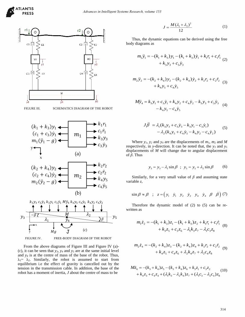
FIGURE III. SCHEMATICS DIAGRAM OF THE ROBOT
(𝑘𝑘2 + 𝑘𝑘4)𝑦𝑦2 (𝑐𝑐2 + 𝑐𝑐4)�̇�𝑦2 𝑚𝑚2(�̈�𝑦2 − 𝑔𝑔)
𝑘𝑘2𝑟𝑟2 𝑐𝑐2�̇�𝑟2 𝑘𝑘4𝑦𝑦5 𝑐𝑐4�̇�𝑦5
𝑚𝑚2
x
y (a)
(b)
(𝑘𝑘1 + 𝑘𝑘3)𝑦𝑦1 (𝑐𝑐1 + 𝑐𝑐3)�̇�𝑦1 𝑚𝑚1(�̈�𝑦1 − 𝑔𝑔)
𝑘𝑘1𝑟𝑟1 𝑐𝑐1�̇�𝑟1 𝑘𝑘3𝑦𝑦3 𝑐𝑐3�̇�𝑦3
𝑚𝑚1
𝑘𝑘3𝑦𝑦3 𝑐𝑐3�̇�𝑦3 𝑘𝑘3𝑦𝑦1 𝑐𝑐3�̇�𝑦1 𝑀𝑀�̈�𝑦4 𝑘𝑘4𝑦𝑦5 𝑐𝑐4�̇�𝑦5 𝑘𝑘4𝑦𝑦2 𝑐𝑐4�̇�𝑦2
J
𝜆𝜆1 𝑀𝑀
𝛽𝛽 −𝛽𝛽 𝜆𝜆2 𝑦𝑦3 𝑦𝑦5
x
y (c)
𝑦𝑦4
𝑀𝑀𝑔𝑔 FIGURE IV. FREE-BODY DIAGRAM OF THE ROBOT
From the above diagrams of Figure III and Figure IV (a)-(c), it can be seen that y3, y4 and y5 are at the same initial level and y4 is at the centre of mass of the base of the robot. Thus, λ1= λ2. Similarly, the robot is assumed to start from equilibrium i.e the effect of gravity is cancelled out by the tension in the transmission cable. In addition, the base of the robot has a moment of inertia, J about the centre of mass to be
21 2( )12λ λ+
=MJ (1)
Thus, the dynamic equations can be derived using the free body diagrams as
1 1 1 3 1 1 3 1 1 1 1 1
3 3 3 3
( ) ( ).................
= − + − + + ++ +
m y k k y k k y k r c rk y c y
(2)
2 2 2 4 2 2 4 2 2 2 2 2
4 5 4 5
( ) ( ).................
= − + − + + ++ +
m y k k y k k y k r c rk y c y
(3)
4 3 1 3 1 4 2 4 2 3 3 3 3
4 5 4 5.................= + + + − +
− −
My k y c y k y c y k y c yk y c y
(4)
1 3 3 3 3 3 1 3 1
2 4 5 4 5 4 2 4 2....( )
(....... )β λ
λ= + − −− + − −
J k y c y k y c yk y c y k y c y
(5)
Where y1, y2 and y4 are the displacements of m1, m2 and M respectively, in y-direction. It can be noted that, the y3 and y5 displacements of M will change due to angular displacement of β. Thus
3 3 1 5 5 2sin ;.. .. sinλ β λ β= − = +y y y y (6)
Similarly, for a very small value of β and assuming state variable z,
( )1 1 2 2 4 4... ... ... ... ... ... .sin ; .. ... ...β β β β≈ =
z y y y y y y (7)
Therefore the dynamic model of (2) to (5) can be re-written as
1 2 1 3 1 1 3 2 1 1 1 1
3 5 3 6 1 3 7 1 3 8.................( ) ( )
λ λ= − + − + + +
+ + − −
m z k k z k k z k r c rk z c z k z c z
(8)
2 4 2 4 3 2 4 4 2 2 2 2
4 5 4 6 2 4 7 2 4 8.................( ) ( )
λ λ= − + − + + +
+ + + +
m z k k z k k z k r c rk z c z k z c z
(9)
6 3 4 5 3 4 6 3 1 3 2
4 3 4 4 1 3 2 4 7 1 3 2 4 8.....( ) ( )
( ) ( )λ λ λ λ= − + − + + +
+ + + − + −
Mz k k z k k z k z c zk z c z k k z c c z
(10)
Advances in Intelligent Systems Research, volume 153
314

2 2 2 27 1 3 2 4 7 1 3 2 4 8
1 3 2 4 5 1 3 2 4 8
1 3 1 3 2 2 4 3 4 2
( ) ( )( ) ( )
( ) ( )..............
λ λ λ λλ λ λ λλ λ
= − + − ++ − + −− − + −
Jz k k z c c zk k z c c zk z c z k z c z
(11)
And the state space representation of (8) to (11) can be expressed as
1 3 1 3 3 3 1 3 1 3
1 1 1 1 1 1 1
2
3 2 4 2 4 4 4 2 4 2 4
4 2 2 2 2 2 2
5
6 3 3 3 4 3 4 1 3 2 44 4
7
8
0 1 0 0 0 0 0 0( ) ( ) 0 0
0 0 0 1 0 0 0 0( ) ( )0 0
0 0 0 0 0 1 0 0( ) ( )
λ λ
λ λ
λ λ
+ +− − − −
+ +
− − =
+ + − − −
k k c c k c k cz m m m m m mzz k k c c k c k cz m m m m m mzz k c k k c c k kk cz M M M M M Mz
1 1 1
1 12
3
4 2 2
2 25
61 3 2 4
7
82 2 2 2
1 3 1 3 1 3 2 4 1 3 2 4 1 3 2 4 1 3 2 42 4 2 4
0 0 0 0
0 0
0 0 0 0
0 0
0 0 0 00 0
0 0 0 0 0 0 0 1
λ λ
λ λ λ λ λ λ λ λ λ λλ λ
+
−
− − − − − + − +
z k cm mz
zz k c
m mzzc czM Mz
k c k k c c k k c ck cJ J J J J J J J
1
1
2
2
0 00 0 0 00 0 0 0
rrrr
(12)
IV. IMPLEMENTATION AND RESULTS In this section, MATLAB simulation results from the
derived equations of motion of the system of (11) are presented. The system is subjected to disturbance inputs from the oscillatory transmission line. A pulse input signal of amplitude 0.1 as shown in Figure V was assumed to be the input. The input will cause the system to move from zero position to 0.1 and then back to zero thereby causing vibration to the robot
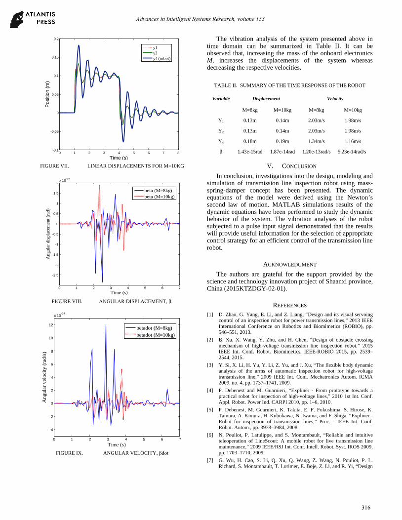
Figure VI shows the displacement responses of m1, m2 and M respectively for the tabulated values of Table I. In addition, the responses of the system are shown in Figure VII when the mass of the onboard components, M was increased from 8Kg to 10Kg. It can be observed that the displacements and velocities of the masses increase with increase of mass, M shown in Table II.
0 1 2 3 4 5-0.02
0
0.02
0.04
0.06
0.08
0.1
Time (s)
Pul
se s
igna
l
FIGURE V. REFERENCE INPUT DISTURBANCE
Similarly, the angular displacement and velocity for the system is shown in Figure VIII and Figure IX respectively for 8kg and 10Kg masses of M.
0 1 2 3 4 5 6 7 8-0.1
-0.05
0
0.05
0.1
0.15
0.2
Time (s)
Pos
ition
(m)
y1y2y4 (robot)
FIGURE VI. LINEAR DISPLACEMENTS FOR M=8Kg.
Advances in Intelligent Systems Research, volume 153
315
0 1 2 3 4 5 6 7 8-0.1
-0.05
0
0.05
0.1
0.15
0.2
Time (s)
Pos
ition
(m)
y1y2y4 (robot)
FIGURE VII. LINEAR DISPLACEMENTS FOR M=10KG
0 1 2 3 4 5 6 7
-2.5
-2
-1.5
-1
-0.5
0
0.5
1
1.5
2x 10
-15
Time (s)
Ang
ular
disp
lace
men
t (ra
d)
beta (M=8kg)beta (M=10kg)
FIGURE VIII. ANGULAR DISPLACEMENT, β.
0 1 2 3 4 5 6 7
-4
-2
0
2
4
6
8
10
12
x 10-14
Time (s)
Ang
ular
vel
ocity
(rad
/s)
betadot (M=8kg)betadot (M=10kg)
FIGURE IX. ANGULAR VELOCITY, βdot
The vibration analysis of the system presented above in time domain can be summarized in Table II. It can be observed that, increasing the mass of the onboard electronics M, increases the displacements of the system whereas decreasing the respective velocities.
TABLE II. SUMMARY OF THE TIME RESPONSE OF THE ROBOT
Variable Displacement Velocity
M=8kg M=10kg M=8kg M=10kg
Y1 0.13m 0.14m 2.03m/s 1.98m/s
Y2 0.13m 0.14m 2.03m/s 1.98m/s
Y4 0.18m 0.19m 1.34m/s 1.16m/s
β 1.43e-15rad 1.87e-14rad 1.20e-13rad/s 5.23e-14rad/s
V. CONCLUSION In conclusion, investigations into the design, modeling and
simulation of transmission line inspection robot using mass-spring-damper concept has been presented. The dynamic equations of the model were derived using the Newton’s second law of motion. MATLAB simulations results of the dynamic equations have been performed to study the dynamic behavior of the system. The vibration analyses of the robot subjected to a pulse input signal demonstrated that the results will provide useful information for the selection of appropriate control strategy for an efficient control of the transmission line robot.
ACKNOWLEDGMENT The authors are grateful for the support provided by the
science and technology innovation project of Shaanxi province, China (2015KTZDGY-02-01).
REFERENCES [1] D. Zhao, G. Yang, E. Li, and Z. Liang, “Design and its visual servoing
control of an inspection robot for power transmission lines,” 2013 IEEE International Conference on Robotics and Biomimetics (ROBIO), pp. 546–551, 2013.
[2] B. Xu, X. Wang, Y. Zhu, and H. Chen, “Design of obstacle crossing mechanism of high-voltage transmission line inspection robot,” 2015 IEEE Int. Conf. Robot. Biomimetics, IEEE-ROBIO 2015, pp. 2539–2544, 2015.
[3] Y. Si, X. Li, H. Yu, Y. Li, Z. Yu, and J. Xu, “The flexible body dynamic analysis of the arms of automatic inspection robot for high-voltage transmission line,” 2009 IEEE Int. Conf. Mechatronics Autom. ICMA 2009, no. 4, pp. 1737–1741, 2009.
[4] P. Debenest and M. Guarnieri, “Expliner - From prototype towards a practical robot for inspection of high-voltage lines,” 2010 1st Int. Conf. Appl. Robot. Power Ind. CARPI 2010, pp. 1–6, 2010.
[5] P. Debenest, M. Guarnieri, K. Takita, E. F. Fukushima, S. Hirose, K. Tamura, A. Kimura, H. Kubokawa, N. Iwama, and F. Shiga, “Expliner - Robot for inspection of transmission lines,” Proc. - IEEE Int. Conf. Robot. Autom., pp. 3978–3984, 2008.
[6] N. Pouliot, P. Latulippe, and S. Montambault, “Reliable and intuitive teleoperation of LineScout: A mobile robot for live transmission line maintenance,” 2009 IEEE/RSJ Int. Conf. Intell. Robot. Syst. IROS 2009, pp. 1703–1710, 2009.
[7] G. Wu, H. Cao, S. Li, Q. Xu, Q. Wang, Z. Wang, N. Pouliot, P. L. Richard, S. Montambault, T. Lorimer, E. Boje, Z. Li, and R. Yi, “Design
Advances in Intelligent Systems Research, volume 153
316
and application of inspection system in a self- governing mobile robot system for high voltage transmission line inspection,” IEEE Int. Conf. Intell. Robot. Syst., vol. 1, pp. 4327–4334, 2009.
[8] H. Beltran and S. Segundo, “Automated Inspection of Electric Transmission Lines : The power supply system Vicente Fuster , Lourdes Perez , Pedro Mayorga,” pp. 3788–3792, 2006.
[9] J. Wang, A. Sun, C. Zheng, and J. Wang, “Research on a new crawler type inspection robot for power transmission lines,” 2010 1st Int. Conf. Appl. Robot. Power Ind. CARPI 2010, pp. 1–5, 2010.
[10] J. Wang, X. Liu, K. Lu, Y. Liu, and J. Zhen, “A new bionic structure of inspection robot for high voltage transmission line,” 2016 4th Int. Conf. Appl. Robot. Power Ind. CARPI 2016, pp. 1–4, 2016.
[11] C. Thorpe and H. Durrant-Whyte, Springer Tracts in Advanced Robotics: Field robots, vol. . 2001.
[12] C. Sun, H. Wang, and M. Zhao, “Vibration analysis of obstacle-avoidance for EHV power transmission lines inspection robot,” IECON Proc. (Industrial Electron. Conf., vol. 2, pp. 2824–2828, 2007.
[13] S. Norman Nise, Control Systems Engineering, 6th ed.. California State …….Polytechnic University: JohnWiley & Sons, 2011, pp.61–72.
[14] J. Guo, X. Zhang, H. Li, and X. Sun, “Mechanism Design and Strength Analysis of Key Components of Flight-climbing-slide Robot for High-voltage Transmission Line Inspection,” in IEEE 7th Annual International Conference on Cyber Technology in Automation, Control and Intelligent System, pp. 200–205, August 2017.
Advances in Intelligent Systems Research, volume 153
317