Embed Size (px)
Citation preview

ROAD VIBRATION SIMULATION
EXPERIMENT: PROGRESS REPORT OF
FINAL DESIGN DESIGN AND DEVELOPMENT OF A ROAD VIBRATION SIMULATOR FOR THE MIAMI UNIVERSITY VIBRATIONS LABORATORY
CAROLYN BASSETTI SARAH BRADY
MANDY FREDERICK JESSICA IRONS MATT WINDON
DR. SHUKLA
MARCH 12, 2004
M I A M I U N I V E R S I T Y S C H O O L O F E N G I N E E R I N G A N D A P P L I E D S C I E N C E
D E P A R T M E N T O F M A N U F A C T U R I N G A N D M E C H A N I C A L E N G I N E E R I N G

2
Road Vibrations Simulation EGR 449 SENIOR DESIGN PROGRESS REPORT
EXECUTIVE SUMMARY
The overall task of the Road Vibration Simulation Team is to design and develop a road
vibration simulator for the Vibration Laboratory at Miami University. The simulator will
involve an actuator that will generate input and software that will measure the response of
the scale model car being analyzed. The main tasks remaining for the team in EGR 449
were to complete the three main segments of the project: Software, Hardware, and
Experiments. At the beginning of the Spring 2004 semester, the major software
requirements were to complete the Graphical User Interface, and to determine how to link
the software with the hardware to input, record and analyze data. The shaker, amplifier, and
cooling system had already been purchased, so the remaining hardware tasks were to design
and build a support structure for the car, and to determine proper setup of the hardware.
Although the team had started creating lab experiments prior to the start of the Spring 2004
semester, the lab reports and user manual still needed to be completed. The team still needed
to begin testing of the actual components, as well as development of laboratory experiments
and instructions for future classes. The design team continues to follow an updated Gantt
Chart to stay on task for the project. This vibration simulator, along with the corresponding
experiments will be developed by mid-April of 2004. It will then be tested by EGR 315
students. Based on their feedback and time remaining, changes will be made accordingly to
improve the experiments written for the simulator.

3
CONTENTS
1. Executive Summary 2
2. Overview 4
3. Progress of the Final Design and Results 9
4. Conclusions and Future Work 20
5. References 21
6. About the Team 21
7. Appendix 22+

4
OVERVIEW
PROBLEM
In order to investigate the design project effectively, the vibrations design team identified
an overall objective, several important constraints, and some general tasks within their
problem definition. The objective for the vibration design team is: to design and implement
a versatile device and corresponding classroom experiments for use in the Miami University
Vibration Laboratory to simulate road vibrations felt by vehicles during normal operation.
The constraints of the project include physical laboratory space, time, and funds. Kreger is
currently the home for the School of Engineering and Applied Science. Room 201 is used as
not only a classroom, but also as a laboratory for many engineering classes. Because of this,
the design team feels lack of space is a constraint. In initial meetings it was determined that
the space available for building, storing and running the experimental setup could only be
the size of a tabletop. The next constraint identified is limited time. EGR 448 and 449 is a
two semester series in which research and design should be completed within the first
semester, leaving the second for building and implementing the projects. With only a school
year, about 8 months, the design team must consider time throughout many aspects of the
project. Finally, the design team has identified funding as an another important constraint
limiting many aspects of design including the components used, specifically the types of
actuators and data analysis software. The four main tasks of this project include (1) design
and build the vibration experimental setup, (2) develop Matlab interface to acquire and
analyze the data from the vibration simulator, (3) develop a lab procedure and manual for
students and instructors, and (4) make all relevant documentation available to all of academia
via Internet.

5
BACKGROUND
Vibration is a very important issue to study and analyze when it comes to design because
it has many effects on the overall system and how the system performs. Safety, human
factors and ergonomics, and style are three primary issues that account for vibrations
considerations in their designs.
PROPOSALS FROM EGR 448
After extensive research and comparing prices and features of different model car
options, the team chose to propose the use of a car from Alro Racing, an importer of
Technokit cars, for their experimental test structure. The cars specifications can be found in
Appendix A. This car is made with metal parts and has four independent suspensions. Each
suspension system consists of 1/5th scale springs as well as hydraulic shock absorbers. The
car is 45 inches long, 14.5 inches wide and 10.5 inches high. Its weight is 21 pounds.
In order to properly support the car while it is being vibrated by the shaker, it is
necessary for the design team to design build a structure that will suspend as well as support
their model car. As the team started looking into the feasibility of suspending the car from
the ceiling, they found that there was not a very good place to do this in the current
vibrations lab. The team also didn’t know what resources the vibrations laboratory would
have in the new engineering building. Finally, they agreed that they wanted to have the entire
experiment be self-contained and mobile. Therefore, the team chose to build an independent
support structure for the car.
In order to correctly simulate road vibrations on the model car, a device called a shaker
will be used to vibrate the car. Through research, the team discovered a company called MB
Dynamics that could provide them with a shaker appropriate for the design experiment.

6
One of the benefits of this particular device is its lightweight, compact design, which make it
portable and easy to setup. Another advantage is that the device is designed to excite small
structures, making it applicable to the team’s scaled-car testing setup. The MB Dynamics
shaker is also compatible with the software the team has available to them to create a
random signal. Because of these features and the fact that MB Dynamics is a reputable
company, the team chose to purchase the modal 50A exciter from MB Dynamics.
Specifications of this shaker can be found in the Appendix B and a picture is seen below in
figure 1.
Figure 1 MB Dynamics Shaker Modal 50A
Also, because the signal that is sent to the shaker needs to be larger than that which can
be generated by the driving software, it is necessary to have an amplifier between the
computer software driving the shaker and the shaker itself. MB Dynamics has a specific
amplifier that is recommended for the modal 50A shaker. Many of the other shaker
companies such as DataPhysics and Ling Dynamics both recommended purchasing an
amplifier that was intended for the shaker that would be purchased. Since no other

7
alternative options are feasible for the project, the team chose to purchase the amplifier from
MB Dynamics.
A cooling system is also needed for the shaker to ensure that it doesn’t overheat while
vibrating the car. The cooling systems are relatively cheap compared to the cost of a shaker
and amplifier, and by having a cooling system, the team will be able to use the shaker at its
peak force if necessary. The cooling system would also allow future experiments to be
performed using the shaker at whatever force was necessary. It was agreed that since the lab
experiment was supposed to be portable and self-contained, it would be best to purchase the
portable cooling system from MB Dynamics. Economically, this would also be the safest
system to buy, since it has not been determined if shop air will be available in the vibrations
laboratory in the new engineering building.
In order to have an interface that the students using the vibration simulation experiment
can use to run the experiment, it was necessary to design a graphical user interface (GUI)
that could work with the Data Acquisition Toolbox software within Matlab. The team
proposed using Matlab software in order to write code to create a user friendly GUI that
could take data and display it in graph windows. The design team created the GUI in
Figure 2 that they proposed would be used to accomplish the aforementioned functions of
a GUI.

8
Figure 2 Proposed final GUI created by team
Because the goal of this entire project is to create a lab experiment that students taking
the vibrations class can use in the Miami University vibrations laboratory, the design team
had to keep in mind the experiments that they would write to go with their project. The
team wanted to focus on intuition when designing the experiments. The first classroom
experiment the design team will to develop and have the vibrations students do in the
laboratory is a basic experiment that introduces students to the equipment as well as the
basics of transfer functions. The second experiment the team will develop for the students
to use perform in the classroom is an experiment that involves changing the location of the
shaker on the car and comparing the different data acquired from the different shaker
locations. Finally, a possible third experiment that the design team would like to develop for
the classroom is an experiment that teaches students about ways to analyze and improve the
accuracy of the data collection technique they have used during the simulation.

9
PROGRESS AND RESULTS OF FINAL DESIGN
OVERVIEW
The team identified the following things to accomplish in EGR 449: finishing build of
support structure for the car and successfully suspending the car from the structure;
finishing writing the code associated with the GUI such that the Data Acquisition Toolbox
in Matlab can take and record and display data obtained via analog inputs connected to the
signal conditioning box that works with the Matlab software; and connecting the entire setup
to work together. The entire setup working together involves having SignalCalc Ace
software, a software program obtained from an outside source, to run the shaker, connecting
the shaker to the car with a glue gun, vibrating the car with the shaker, connecting
accelerometers to the car to receive data, having the Matlab software read, record, and
display the results via a user friendly GUI. Although, during EGR 448, the team proposed
the GUI shown in Figure 2, through software development and the writing of the code the
team developed a new GUI shown in Figure 3. Since the GUI and experiment would be
used by students it was important that it be well organized, and easy to use. The GUI found
in Figure 3 is the final GUI to be used and further developed in EGR 449.

10
Figure 3 Final GUI created by team for use in lab
TEST COMPONENTS
At the beginning of the semester, the team had in its possession most of the necessary
components for the experimental setup. This included the shaker and accessory kit, the
scale model car, the amplifier, the computer software, the accelerometers, and the signal
conditioning box. This list excluded the final support structure (construction discussed
later), and the correct code for the user interface (development discussed later). This
enabled the team to begin testing of experimental components at the first meeting of the
semester (1/20/04). Testing of components is necessary early on to ensure all equipment is
working properly. This allows the team to catch possible present or future errors in the
experimental setup. Testing of the road vibrations simulator equipment consisted of the
following:

11
• Hardware
o Assembling components of shaker not assembled prior to shipment
o Testing shaker, amplifier, and cooling system to ensure proper operation
o Using temporary support structure to suspend car and test shaker on car
• Software
o Writing and troubleshooting software to ensure code was correct and free of
errors
o Running computer software to establish correct connections between data
collection components, shaker and amplifier
o Checked accuracy of shaker using the SignalCalc Ace software and a laptop
SUPPORT STRUCTURE
The support structure has one main function: to support the weight of the car in a
manner that will isolate it from outside disturbances and yet be able to vibrate freely in
response to the stinger touching the car. The team came up with three potential options for
the support structure. Each of these preliminary ideas involved suspending the car using
bungee cords. The main benefit to bungee cords was that the cords would have a minimal
impact on the natural vibration response of the car. The first idea was to purchase an engine
hoist. This would have been a very expensive option, but it could have future applications
for the engineering department beyond this project that could potentially justify the cost. It
would also be the easiest option to manufacture, since the structure could simply be
purchased. The next idea was to purchase sawhorses as the basis for our support structure.
Once again, the sawhorses could have additional value to the department beyond this
project. The final option was to build a support structure entirely out of materials available in

12
the machine shop. Although this would require the most work from the team, it would be
free of cost and would allow the team to design the support structure to the exact necessary
specifications. This final choice was found to be the best option for the team. The selection
matrix can be seen in Figure 4.
Selection Matrix: 1(low) - 5(high)
Functionality CostEase of
Use Ease of
Production Total: Engine Hoist 3 1 3 5 12
Sawhorses 3 3 4 4 14 Build Our
Own 5 5 4 2 16 Figure 4 Support Structure Selection Matrix
After much deliberation between team members and the machine shop expert, Jeff
Peterson, it was decided to first build a temporary structure based on the same principles
desired in the permanent structure. This would allow the team to begin testing until the final
structure was designed. Two posts from an old chalkboard stand were found in the scrap
pile. They were made of wood and had steel cross iron brackets already in place. The team
measured the distance needed to have between the shaker and the bottom of the car chassis.
Based upon this distance, the brackets were moved up on the posts. A strong steel iron
corner bar was found in the scrap pile that was long enough for the car to be suspended
below it and between the posts. The iron corner bar already had a couple holes in it that
were large enough for the bungee cord hooks to go through. The team used two C-clamps
and clamped this iron corner bar to the brackets. A pack of bungee cords was acquired from
the machine shop. The team then began to experiment with which length of bungee cords
to use and how many. The fewer bungee cords used, the better because this meant less
factors influencing the vibration of the car.

13
Three bungee cords were tried and various holes in the car were used to attach them to.
The team decided that the best place for the cords to attach were on the metal chassis.
There were not many options for this type of attachment, however. The car needed to be
level, and the holes available could not be paired with bungee cords of appropriate length.
So, with Jeff Peterson’s aid, four C-brackets were fashioned from thick scrap aluminum.
Two of these C-brackets would be attached with spacers in the rear of the car and the other
two attached to the car chassis in the front. To attach them in the front, holes were drilled
in the chassis on the angled part. The angled part was drilled because this would not lessen
the amount of places the shaker stinger could reach; the shaker stem could only reach the
level parts of the car.
While the team was making the C-brackets with the bending machine, drill press, and
grinder, the team also worked on making the permanent support structure. This used the
same basic parts from the temporary structure. To make the permanent support structure,
holes were drilled with a hand drill in the iron corner bar as well as the cross iron brackets.
Holes were also drilled in marked locations so that the bungee cords could be attached to
the iron corner bar directly above their attachments on the car chassis. Bolts, nuts, and lock
washers were then used and the iron corner bar was permanently attached to the cross iron
brackets. The car was then put underneath the structure and hung from four bungee cords
of equal lengths.
After hanging the car, it was discovered that it still was not completely level. The
team went back to the machine shop and found two long bars of unistrut-type steel. They
were then attached to the iron corner bar with nuts, bolts, and washers. After locating the
proper location for the bungee cords hanging from these steel pieces, they were cut so that

14
they were not unnecessarily long. These were then permanently attached to the corner iron
with spacers. The final support structure can be seen in Figure 5.
Figure 5 Final support structure with car attached CODE DEVELOPMENT
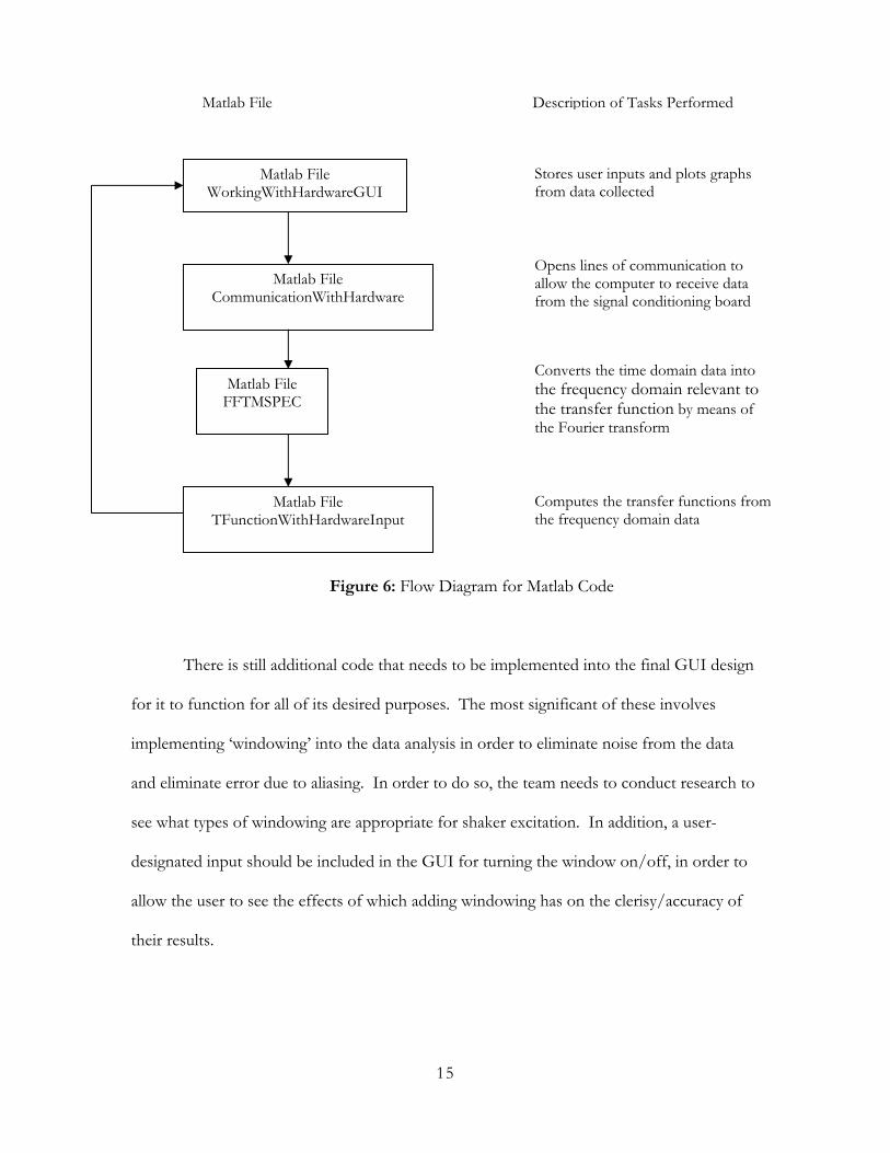
A large portion the team’s progress this semester has been in writing the code for
our graphical user interface (GUI). Several different files were created for this purpose, the
idea being that using many different files, each with a separate purpose, would help in the
troubleshooting process as well as aid in the overall understanding of how things work.
Figure 6 shows a flow diagram of the communication between the Matlab files created, as
well as gives a brief description of the tasks performed within each file.
15
Figure 6: Flow Diagram for Matlab Code
There is still additional code that needs to be implemented into the final GUI design
for it to function for all of its desired purposes. The most significant of these involves
implementing ‘windowing’ into the data analysis in order to eliminate noise from the data
and eliminate error due to aliasing. In order to do so, the team needs to conduct research to
see what types of windowing are appropriate for shaker excitation. In addition, a user-
designated input should be included in the GUI for turning the window on/off, in order to
allow the user to see the effects of which adding windowing has on the clerisy/accuracy of
their results.
Matlab File FFTMSPEC
Matlab File CommunicationWithHardware
Matlab File TFunctionWithHardwareInput
Matlab File WorkingWithHardwareGUI
Opens lines of communication to allow the computer to receive data from the signal conditioning board
Converts the time domain data intothe frequency domain relevant to the transfer function by means of the Fourier transform
Computes the transfer functions from the frequency domain data
Stores user inputs and plots graphs from data collected
Matlab File Description of Tasks Performed
16
As the team was working on developing their code, they ran into a serious issue with
the Matlab license and its corresponding capabilities in terms of analog input and output
capacities. Through their investigation, the team discovered that, despite their original
beliefs, the current Matlab software they were licensed to use did not have analog output
capacity to communicate with the current National Instruments hardware available in the
vibrations laboratory. Since the team had originally planned to drive the shaker using the
Matlab commands and the analog output communication capability, a new technique needed
to be developed. The team is now planning on driving the shaker using the aforementioned
SignalCalc Ace program software.
When the team began to write the code for the final GUI, they started from scratch,
using the goal GUI they had designed last semester as a guide for their overall work. As the
team gained a better understanding of how the interaction between the buttons, graphs, and
corresponding code for the GUI worked, they began making slight changes in their overall
goal for the GUI to reflect the capabilities of the system. For instance, instead of saving the
input of each accelerometer separately, On/Off boxes designating the states of each
accelerometer are used. As stated earlier, additional inputs (windowing, etc.) still need to be
added to the GUI design; however, the change thus far resulting from progress can be seen
in the differences between the figures 1 and 2. Also, despite these small changes, the overall
design for much of the GUI (input/output/and transfer function) remains constant.
FINAL DESIGN
Figure 7 shows the overall system setup for the experiment. This includes the hardware
and software components of the design. The flow of information within this experimental
setup is shown in Figure 8. First, a random signal is generated through the SignalCalc

17
software on the laptop. Since computers deal with digital signals and the shaker provides an
analog signal, the signal must pass through a signal conditioning board to convert the signal
to analog. This signal is sent to the amplifier, then on to the shaker, where the stinger
receives the random signal and applies the corresponding forces to a given location on the
car. Accelerometers placed on various locations on the car measure the vibration response
output from the car, and the data is sent back to the signal conditioning unit, which sends
along a digital signal to the computer. The graphs of the input, output, and transfer function
are then plotted on the GUI in the Matlab software program so that the user can easily
observe the data.
Figure 7 Experimental Setup
Shaker
Amplifier
Computer with Matlab Analog Input
Signal Conditioning Board
Cooling System
NOTE: Laptop with Signal-generating Capability is necessary but NOT included in the picture Support
Structure

18
Figure 8 Flow chart of information in experimental setup

19
CONCLUSIONS AND FUTURE WORK
At this point in the semester, the team still has several tasks to complete in the future. The
team has continued research on writing vibrations experiments since the end of last
semester. Having focused work up to this point on the final support structure (hardware)
and working user interface (software), the team has not accomplished anything tangible in
terms of the experiment aspect of the design. Because of this, the team plans to focus on
the following:
• Writing of experiments for use with experimental setup
• Writing a lab manual for the experimental setup
• Conducting user tests on experiments and experimental setup
• Posting information on internet
The software has been established to work fundamentally in that it completes the basic
functions of collecting data and displaying it on a graph. Using an iterative process of user
testing and GUI code development, the team hopes to achieve a final user interface that is
user friendly.
The team’s final design has several advantages. First, the team has kept a continual focus on
enhancing pedagogy. They feel it is important to consider the enrichment of education in
every step of the design and implementation of the experimental setup. A second advantage
of the final design is its mobility. The team has considered mobility in every aspect of the

20
experimental setup. This includes a mobile cooling system, a mobile support structure, and a
shaker that can be easily moved by one or two people. This is an advantage for the future
since the engineering department will soon be relocated. A final advantage is user
friendliness. The team realized early on that its target user was the student. Because of this
the team has focused on making the setup as well as software and soon the experiments
themselves easy to use. This is important since lab time will be limited and the student
should not have to spend time assembling components or experiencing errors.
REFERENCES
ALRO Racing: http://www.alroracingusa.com/ GUI Ergonomics: http://cognitivevent.com/gui.html
GUI Ergonomics: http://www.omnica.com/omniview_industrial_design2.htm Math Works: www.mathworks.com Mathworks. Data Acquisition Toolbox: For Use with Matlab User’s Guide. Version 2.
2001. The Mathworks, Inc. Natick, MA. MB Dynamics: www.mbdynamics.com Modal Analysis: http://www.mecha.uni-
stuttgart.de/Forschung/forschung_exp_meth/forschung_expmodal_en.htm Modal Analysis: http://www.gmi.edu/~drussell/GMI-Acoustics/Modal.html Modal Analysis: http://www.mts.com/nvd/PDF/1992_AMATLST.pdf National Instruments: www.nationalinstruments.com Technokit: http://www.technokit.it
ABOUT THE TEAM
There was a wide variety of engineering background within the group, with Manufacturing,
Management, Mechanical, and Environmental majors represented. This variety of
backgrounds has led to a wide array of skills, and many different approaches to problem
solving. Each member of the group shares the same feeling learning style. The group was

21
able to take advantage of the shared learning styles by taking a hands-on approach to the
project, for instance scheduling a trip to see a full scale road vibration simulator at the
University of Cincinnati. Two of the group members, Sarah and Mandy, have taken a
Vibrations class at Miami University, and Mandy spent last summer at Miami assisting in
vibrations research. Sarah and Jessica also had professional experience in the Engineering
Industry. Their prior knowledge and ability to share this knowledge with the rest of the team
has greatly benefited the group.
Each member of the group was interested in the subject matter behind this project, and
the team wanted to be able to help improve the Engineering Department at Miami
University. In order to simultaneously proceed with different segments of the project, the
team divided into subgroups, but continued to meet as an entire group at least once a week.
This ensured that every member of the group was aware and educated of all aspects of the
project. In EGR 448, the group divided into 2 main sections. Due to their experience with
Matlab, software development, and vibrations software, Jessica, Mandy, and Sarah focused
on software development for the group. Due to their experiences as Engineering
Management majors, Carolyn and Matt worked primarily on the selection and acquisition of
hardware for the experiment. In EGR 449, Sarah joined Carolyn and Matt to work on the
hardware segment of the project. By doing this, the group was able to maximize the skills of
each member and increase the overall productivity of the group.

22
Appendix A
Car Specifications

23
Appendix B
Shaker Specifications