Embed Size (px)
Citation preview
© Reda Bendraou Software Engineering – Course 2: Modeling with UML
Modeling with UML
Reda Bendraou
http://pagesperso-systeme.lip6.fr/Reda.Bendraou/

© Reda Bendraou Software Engineering – Course 2: Modeling with UML
Modeling
-Definition
-Why Modeling?
-Which language to use?
-Software=Code?

© Reda Bendraou Software Engineering – Course 2: Modeling with UML
What is Modeling?
Building an abstract representation of reality
Abstraction =
• Ignoring the insgnificant details (depending on the aspects/viewpoint we are interested in)
• Bringing out the most important details
– Important= What it is imporant or not depends on the purpose of the model (is it just for communication? Code generation? Verification?) and which aspect of the system you want to capture?
© Reda Bendraou Software Engineering – Course 2: Modeling with UML
Modeling: an other definition!
Modeling, in the broadest sense, is the cost-effective use of something in place of
something else for some cognitive purpose. It allows us to use something that
is simpler, safer or cheaper than reality instead of reality for some purpose
A Model represents reality for the given purpose; the model is an abstraction of
reality in the sense that it cannot represent all aspects of reality. This allows us
to deal with the world in a simplified manner, avoiding the complexity, danger
and irreversibility of reality
Par Jeff Rothenberg, « The nature of modeling »
• Attention : abstraction != simplification?
– Modeling may ease understanding the problem, communicating around its
different aspects but it never simplifies the problem itself
© Reda Bendraou IDM – UPMC Cours : Model-Driven Engineering
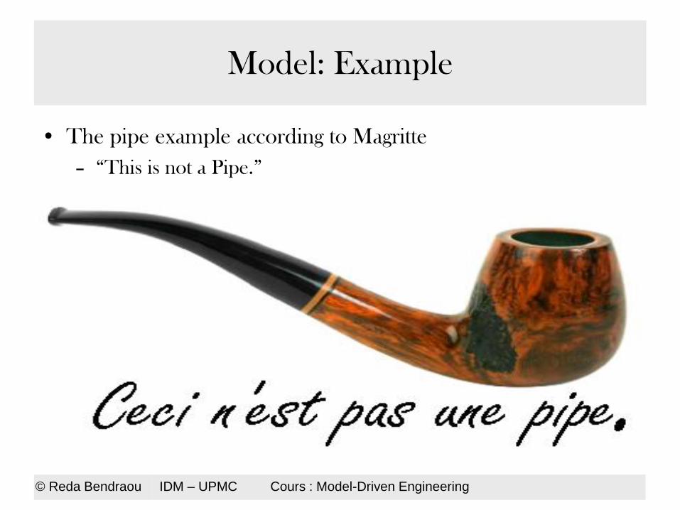
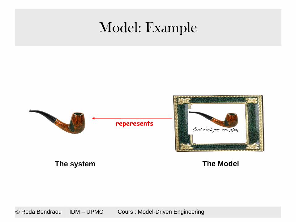
Model: Example
• The pipe example according to Magritte
– “This is not a Pipe.”
© Reda Bendraou IDM – UPMC Cours : Model-Driven Engineering
Model: Example
reperesents
The system The Model
© Reda Bendraou IDM – UPMC Cours : Model-Driven Engineering
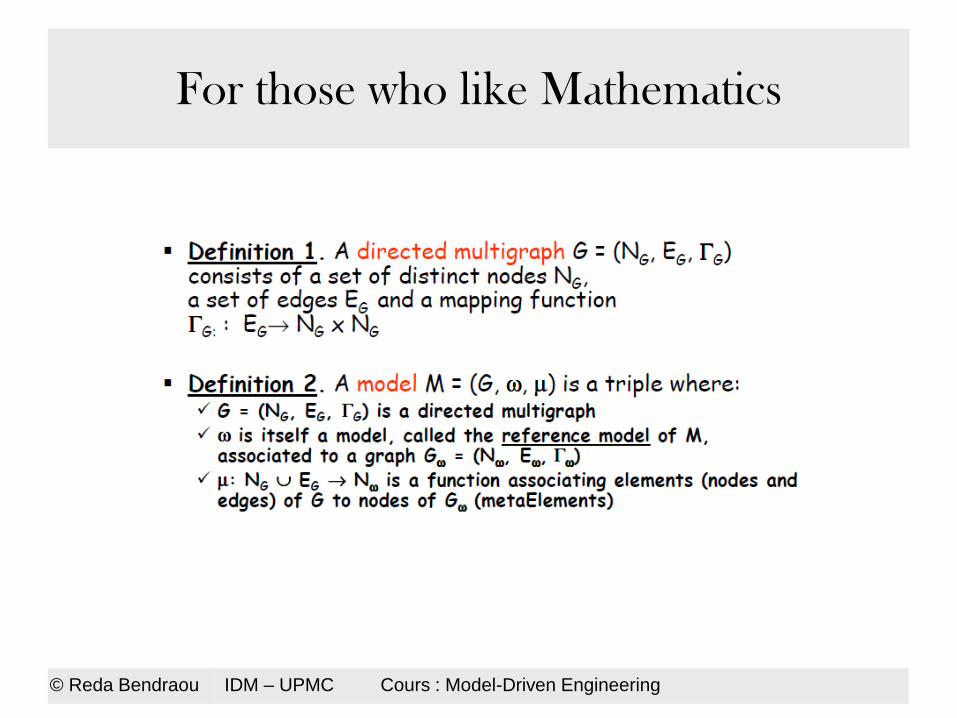
For those who like Mathematics

© Reda Bendraou Software Engineering – Course 2: Modeling with UML
Abstraction Vs Viewpoint
Example: Google Maps
• Different levels of abstractions
• Different viewpoints

© Reda Bendraou Software Engineering – Course 2: Modeling with UML
Why Modeling?
To communicate
• Many stakeholders may participate in the development process
– Clients, managers, marketing, engineers, developers etc.
• Big projects may involve hundreds of people working in different locations
– Example: the IBM Jazz project (more than 400 developers around the word)
• Code is not abstract enough to be used for communication!
– Computer science history:
• raising the level of abstraction away from machine-centered representation
and towards human-centred representations
• today’s models are tomorrow’s programs
• Outsourcing, offshore …Etc

© Reda Bendraou Software Engineering – Course 2: Modeling with UML
Why Modeling?
To manage complexity
• Examples: Google
– More than 1,7 Million servers (2012), a huge processing capacity
– 4 billions of requests per day!, 40 000 request per second!
• Models allow you to think about your design more easily than digging into the code (very often, not your code!)
• Separation of concerns – The system is viewed by different viewpoints
– Code (except for Aspect-Oriented Programming) tend to mix all concerns of a software together in the same place (i.e., file, sections in a file)

Why Modeling ?
a multi-dimensional representation
© Reda Bendraou Software Engineering – Course 2: Modeling with UML
Full Software
Model
Class Diagram
Object Diagram
Use Case Diagram
Activity Diagram
Protocol Diagram
IOCL Expressions
© Reda Bendraou Software Engineering – Course 2: Modeling with UML
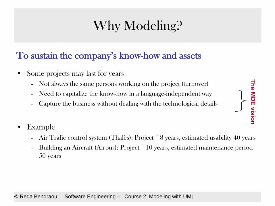
Why Modeling?
To sustain the company’s know-how and assets
• Some projects may last for years
– Not always the same persons working on the project (turnover)
– Need to capitalize the know-how in a language-independent way
– Capture the business without dealing with the technological details
• Example
– Air Trafic control system (Thalès): Project ~8 years, estimated usability 40 years
– Building an Aircraft (Airbus): Project ~10 years, estimated maintenance period
50 years
Th
e M
DE
vis
ion

© Reda Bendraou Software Engineering – Course 2: Modeling with UML
Why Modeling?
For a better productivity • Code generation from models
– The MDE vision(Model-Driven Engineering)
– 100% of code being generated in some domains
• Exp. CMS, configuration files, databases, etc.
• Playing with Variability
– The Software Line Product (SPL) vision
• One generic model, multiple features possible to extend the product
• Example: Nokia
– 3 Billions of cellphones sold (250 Millions/year , 2013, 450 M, in 2010)
– Hundreds of software versions
– Time-to-market ~3 months

© Reda Bendraou Software Engineering – Course 2: Modeling with UML
Software = Code ?
• Do you really still think that?
• Not the case anymore:
– Software= Documentation + Models+ Code
– Several models, views for the same Software
– Documentation can be partially generated from Models
– Code can be partially generated from Models (100% in some cases)
• With Models today we can have
– A better productivity, better communication and a better specification of the
problem/system under study
© Reda Bendraou Software Engineering – Course 2: Modeling with UML
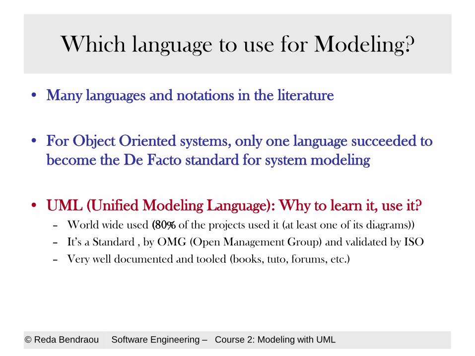
Which language to use for Modeling?
• Many languages and notations in the literature
• For Object Oriented systems, only one language succeeded to
become the De Facto standard for system modeling
• UML (Unified Modeling Language): Why to learn it, use it?
– World wide used (80% of the projects used it (at least one of its diagrams))
– It’s a Standard , by OMG (Open Management Group) and validated by ISO
– Very well documented and tooled (books, tuto, forums, etc.)

© Reda Bendraou Software Engineering – Course 2: Modeling with UML
UML
- History
- Possible ways of using UML
- The development process with UML
-UML diagrams/Viewpoints

© Reda Bendraou Software Engineering – Course 2: Modeling with UML
Birth of UML
• Between 89 and 94 : the number of OO methods went from 10 to 50
• Every method used its own notation, although they shared many
common points
• In the mid 90, G. Booch, I. Jacobson & J. Rumbaugh, known as los
3 amigos, collaborated to create UML

© Reda Bendraou Software Engineering – Course 2: Modeling with UML
Dates

© Reda Bendraou Software Engineering – Course 2: Modeling with UML
UML: Principal influences
• Booch: notion of sub systems
• Fusion: sequence diagrams (numbering messages, operations)
• Gamma, et al.: Frameworks, patterns, et notes
• Harel: Statecharts
• Jacobson: use cases
• Bertand Meyer: Pre- et post-conditions
• Odell: notion of events
• OMT: Associations
• Shlaer-Mellor: object lifecycle
© Reda Bendraou Software Engineering – Course 2: Modeling with UML
UML Today
• Widely used
• In many domains
– OO, Real Time, Deployment, Requirement, …
• UML IS NOT A METHOD
– RUP (Rational Unified Process) is a method
• Only few people really know the standard
– 5% strong comprehension
• UML is criticized because it is not enough formal

UML Today
• Paradigms:
– Structural: Object-oriented + relational + component-based
– Behavioral: Imperative + event-based + concurrent
• General purpose (as opposed to Domain Specific Modeling Language)
• Visual (Diagram Interchange) and textual (OCL, AFL)
• Subset with formalized semantics: Foundation UML (fUML)
• Modularly structured in packages
• Self-extensible: profiles
• No competitor
• Very large:
– Infrastructure: 226p.
– Superstructure: 740p.
– DI: 86p.
– OCL: 238p.
– fUML: 369p.
– AFL: 441p.
• Lacks a library of built-in classes
© Reda Bendraou Software Engineering – Course 2: Modeling with UML
© Reda Bendraou Software Engineering – Course 2: Modeling with UML
3 possible ways of using UML
(1) As a sketching, brainstorming language… (to explore)
– To quickly communicate and brainstorm
– Models not specially sound or complete
– Objectives: to analyze the problem, think, decide(brainstorming)
– Probably the way most people use UML

© Reda Bendraou Software Engineering – Course 2: Modeling with UML
3 possible ways of using UML
(2) As a language for model specification… (to design) – Sound and complete models, ready to be used for code
generation/implementation
– Models used for advanced design choices
– Can be models obtained through Reverse Engineering
• To improve the design,
• To detect package dependencies and cycles, applying design patterns, etc.
– Ability to use Round trip Engineering
– Objectives: (1)+ desgin , sustain the business, to generate partially the code
– The way UML is used in complex and big projects
© Reda Bendraou Software Engineering – Course 2: Modeling with UML
3 possible ways of using UML
(3) As a programming language (better productivity)
• Not mature enough
« It’s worth using UML as a programming language only if it results in something that’s significantly more productive than using another programming language »
– Martin Fowler, UML Distilled
• To put everything in the model, even operations code: Productivity Vs Readability
– Some initiatives Executable UML, J, xOCL, etc.
• The ability to simulate and to execute Models
• The tooling is not mature enough!!!
• Objectives: (2) + 100% code generation

© Reda Bendraou Software Engineering – Course 2: Modeling with UML
In this Course
• We will use UML like in (1) and (2) Options
• We will demonstrate why (3) is not mature enough

© Reda Bendraou Software Engineering – Course 2: Modeling with UML
The development process with UML
• UML is process/method independent
• However the process development with UML is viewed as:
– Iterative & Incremental
– Use case driven
– Architecture oriented

© Reda Bendraou Software Engineering – Course 2: Modeling with UML
Different development phases covered by UML
• Requirement
• Analysis
• Design
• Implementation
• Testing
• Deployment
• Maintenance
Well covered by UML
Arguable:
implementation: if UML is used with option (3). If
you have good code generators
Testing: some test cases can be generated from
sequence diagrams….but not sufficient
Deployment: UML provides a diagram for that but
no automation for this step
Maintenance: through round trip engineering
reverse engineering, the application of design
patterns.

© Reda Bendraou Software Engineering – Course 2: Modeling with UML
UML: a set of diagrams and viewpoints
© Reda Bendraou Software Engineering – Course 2: Modeling with UML
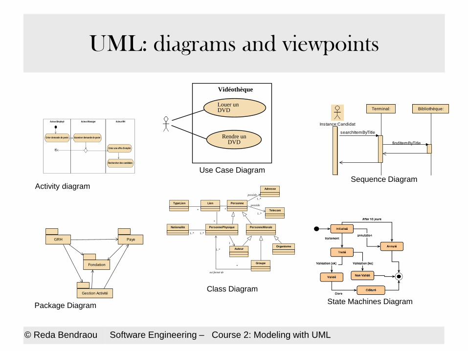
UML: diagrams and viewpoints
Package Diagram
GRH Paye
Fondation
Gestion Activité
Instance:Candidat
Bibliothèque:Terminal:
searchItemByTitle
findItemByTitle
Sequence Diagram Activity diagram
Acteur:Employé Acteur:Manager Acteur:RH
Créer demande de poste
Créer une offre d'emploi
Examiner demande de poste
Rechercher des candidats
Telecom
Organisme
PersonnePhysiqueNationalite PersonneMorale
est formé de
1..*1..*
LienTypeLien
*
*
Personne
Adresse
1..*
*
1..*
possède
possède
1..* Auteur
Groupe*
1
Class Diagram
Vidéothèque
Louer un DVD
Rendre un DVD
Use Case Diagram
State Machines Diagram
© Reda Bendraou Software Engineering – Course 2: Modeling with UML
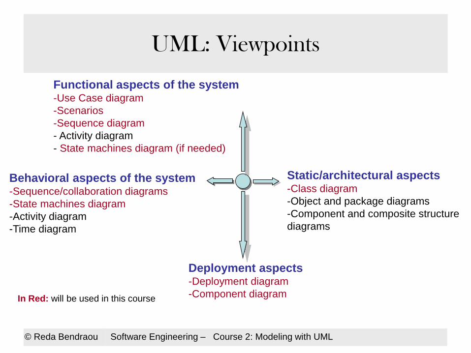
UML: Viewpoints
Static/architectural aspects -Class diagram
-Object and package diagrams
-Component and composite structure
diagrams
Behavioral aspects of the system -Sequence/collaboration diagrams
-State machines diagram
-Activity diagram
-Time diagram
Functional aspects of the system -Use Case diagram
-Scenarios
-Sequence diagram
- Activity diagram
- State machines diagram (if needed)
Deployment aspects -Deployment diagram
-Component diagram In Red: will be used in this course

© Reda Bendraou Software Engineering – Course 2: Modeling with UML
UML: Functional viewpoint
- Use case diagram
-Scenarios

© Reda Bendraou Software Engineering – Course 2: Modeling with UML
UML: Functional viewpoint
• Many UML diagrams can be used to capture what the system is
supposed to offer in terms of services/ functionalities
– Use case diagram is one of the most used one!
• Use cases can be documented with:
– Scenarios (naturel language),
– Sequence diagrams as a graphical representation of scenarios
– Activity diagrams to express in more details the workflow, data and
artifact created/exchanged to realize a service
• A very important starting point a UML-based development
process
– Use case driven!
© Reda Bendraou Software Engineering – Course 2: Modeling with UML
Use Case Diagram
A user-oriented diagram
• A system is built to answer user’s needs:
– They know what the system is expected to do but not how
– Some of them know part of the expected services
• You should pay attention to their requirements!! (otherwise =>see
next slide)

Otherwise!
© Reda Bendraou Software Engineering – Course 2: Modeling with UML

© Reda Bendraou Software Engineering – Course 2: Modeling with UML
Use Case Diagram
Use Case diagram constituents:
– Actors
– Use Cases
– The system being modeled
– Relations • Associations, Generalization, dependencies
Goals:
– To communicate around the system’s expected services
– Identify System’s functionalities (in a graphical way)
– To highlight the system’s boundaries
– Can be used to specify some functional tests

© Reda Bendraou Software Engineering – Course 2: Modeling with UML
Use Case: Actor
• An Actor represents a role undertaken by an external entity that interacts
(directly) with the system (UML2.° Spec, OMG)
• Can be a human (ex. Agent, cashier, client, etc.), a machine (ex. server,
printer, etc.) or another software (ex. Stock management, etc.);
• Graphical notations
Stock IS

UML (c) Justin Templemore-Finlayson, 2004-2011 22
Identifying actors
• To help find actors in your system you should ask the following questions:
Who is the main customer of the system?
Who obtains information from this system?
Who provides information to the system?
Who installs the system?
Who operates the system?
Who shuts down the system?
What other objects intract with the system?
Who will supply, use, or remove information from the system?
Where does the system get information?
• The system itself can also be an actor
– For tasks that happen regularly or at a preset time
– Indicated with an no actor, or an actor named “system”
Use Case: Actor
© Reda Bendraou Software Engineering – Course 2: Modeling with UML
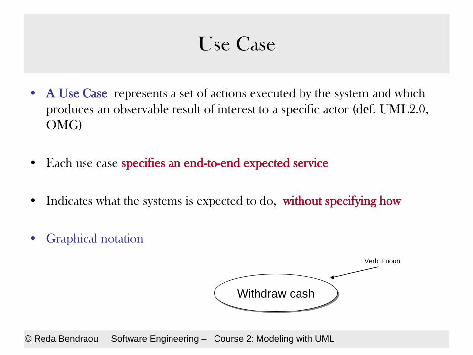
Use Case
• A Use Case represents a set of actions executed by the system and which
produces an observable result of interest to a specific actor (def. UML2.0,
OMG)
• Each use case specifies an end-to-end expected service
• Indicates what the systems is expected to do, without specifying how
• Graphical notation
Withdraw cash
Verb + noun

Use Case
How to identify use cases ?
• What are the functionalities proposed by the system?
– Each functionality is represented as a use case.
• What are the interactions Actor-System?
For each identified actor
– Identify the functionalities used by this actor.
– Who maintain the system
• What are the events received by the system?

© Reda Bendraou Software Engineering – Course 2: Modeling with UML
Use Case: System’s boundary box
• The system’s boundary box represents the limits of the system.
Everything outside this box, is supposed to be provided or
designed in the context of another system
• Graphical notation
Vidéothèque
Rent a DVD
© Reda Bendraou Software Engineering – Course 2: Modeling with UML
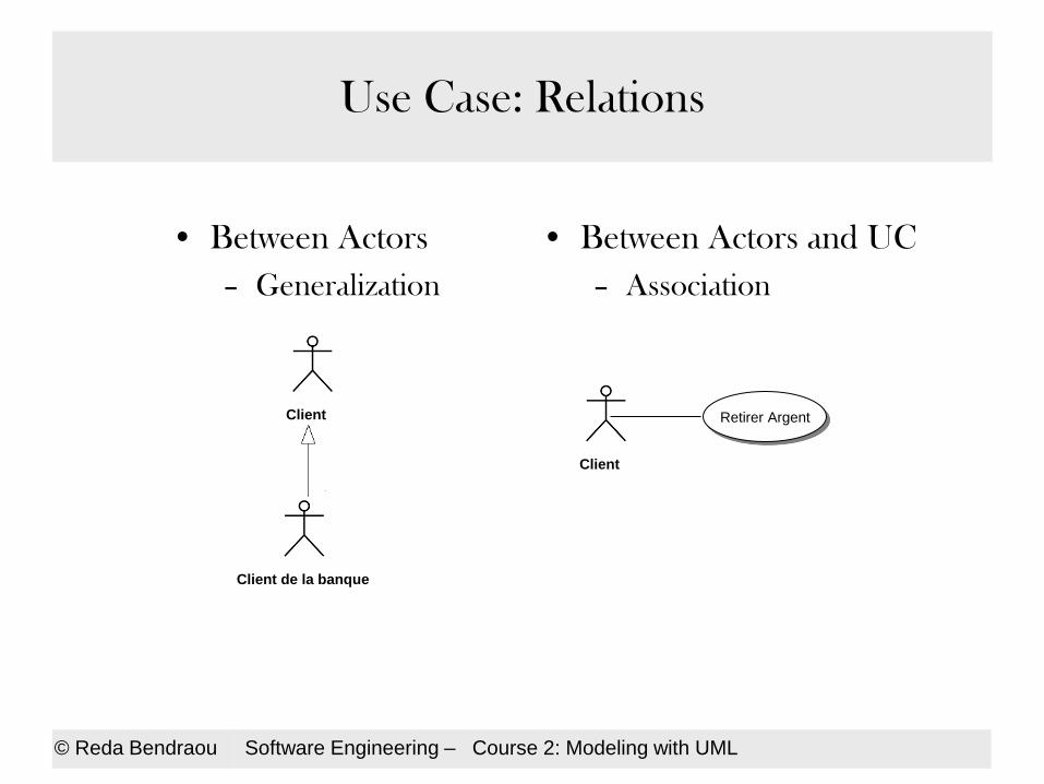
Use Case: Relations
• Between Actors
– Generalization
Client
Client de la banque
• Between Actors and UC
– Association
Client
Retirer Argent

© Reda Bendraou Software Engineering – Course 2: Modeling with UML
Use Case: Relations
Between Use cases: 3 kinds of relations
• Generalization : the sub-UC extends the super-UC with more action. Source of ambiguity À Please avoid using this relation (not allowed in this course)
• Inclusion (<<include>>): the source UC necessarily needs the target use case for its execution!
– Use it to factorize common actions between different use cases
– To highlight an important sub-functionality
• Extension (<<extend>>): a base UC can be Optionally extended by another UC for its execution.
• If you want to be precise, when the inclusion or the extension happens, you can add an Extension Point
Funds Transfer
Funds Transfer
On Line
Withdraw Cash Identification
<<include>>
Withdraw Cash
Extension Point:
check. balance
Check Balance
<<extend>>
Condition: User wants to check balance first
Point d’extension: check balance
© Reda Bendraou Software Engineering – Course 2: Modeling with UML
Use Case Diagrams
Some advices
• Granularity of UC => 2 UC Vs.15 UC
– « There is a magic number:7, plus or minus 2. This refers to the number of concepts that
we humans can keep in mind at any one time » (H.A. Miller, 1958)
– Many UC may reduce readability of your diagram. More details can be specified in
scenarios instead
– Some people can go for hierarchical decomposition=> not advised by the standard
• Please avoid the misuse (abuse) of <<include>>, <<extend>>
• Remember that the UML dev. Process is UC oriented
© Reda Bendraou Software Engineering – Course 2: Modeling with UML
Use Case Diagram: Conclusion
• Used very often in software projects
– Gives an abstract description of what it is expected from the system (the
WHAT)
– Very easy to learn, to read
• UC describes the WHAT and Never the HOW!!
• The HOW can be described using Scenario, to specify how each UC is
realized

© Reda Bendraou Software Engineering – Course 2: Modeling with UML
Scenarios
© Reda Bendraou Software Engineering – Course 2: Modeling with UML
Scenarios
• They represent instances of UC – A scenario describes the actors interaction with the system
• In natural language but usually represented using Sequence Diag.
• Very used and useful for requirements specification (can hardly do without)
• They can help you identifying other UC
© Reda Bendraou Software Engineering – Course 2: Modeling with UML
Scenarios
• Every UC will be specified using several scenarios
• First with a Happy Path scenario(the world is perfect ;))
• Secondary scenarios (exceptions, alternatives)
• UC + Detailed scenarios for each UC => Functional
requirement specification

Use case example Name: Enroll in seminar
Identifier: UC03
Description: Enroll an existing student in a seminar for which she is eligible. In case of a schedule conflict or insufficient prerequisites, she will not be allowed to enroll.
Preconditions: The student is registered at the university
Postconditions: The student is enrolled in the seminar or the system is unchanged.
Basic course of action:
1. The UC begins when a student indicates she wants to enroll in a seminar.
2. The student identifies him or herself. Include UC04 « Connect to the system »
3. The system verifies that the student has not yet reached the number of seminars he has paid for.
4. The system checks the seminars that the student has already followed, displays the list of seminars for which he satisfies the pre requisites.
5. The student selects the seminar in which she wants to enroll.
6. The system displays the student’s current
timetable superimposed with the new seminar.
7. The system asks if the student still wants to
enroll.
8. The student confirms.
9. The system updates the student’s timetable
with the new seminar and publishes it.
10. The system asks if the student wants a
printed copy of his new timetable.
11. The student indicates yes.
12. The system prints the new timetable for the
semester.
13. The student takes the timetable
14. The UC ends when the student takes her
timetable. 29
Scenarios: Example

Use case example (continued!)
Name: Enroll in seminar
Identifier: UC03
Description: Enroll an existing student in a seminar for which she is eligible. In case of a schedule conflict or insufficient prerequisites, she will not be allowed to enroll.
Preconditions: The student is registered at the university
Postconditions: The student is enrlled in the seminar or the system is unchanged.
Alternate course A: The student has
already enrolled in all the seminars she has paid for.
A4. The system informs the student that she cannot enroll in any more seminars unless she pays more fees.
A5. The system invites the student to return after paying new fees.
A6. This UC ends.
Alternate course B: The student does not have sufficient pre requisites for any seminar
B4. The system informs the student that she does not have sufficient pre requisites to follow any more seminars.
B5. The UC ends.
Alternate course C: The student does
not like the new timetable and decides not to enroll
C8. The student cancels the enrolment process.
C9. The UC ends. 30
Scenarios: Example (continued)

© Reda Bendraou Software Engineering – Course 2: Modeling with UML
Scenarios: Example
• Try the Withdraw cash HP scenario

© Reda Bendraou Software Engineering – Course 2: Modeling with UML
Sequence and Activity Diagrams
• They can also be used to describe UC actions and to visually
represent scenarios
• Can describe some complex behavior (Activity Diagram)
• We will introduce them in the behavioral viewpoint

© Reda Bendraou Software Engineering – Course 2: Modeling with UML
Lectures
• Software Engineering,
– Ian Sommerville, Addison Wesley; 8 edition (15 Jun 2006), ISBN-10: 0321313798
• The Mythical Man-Month
– Frederick P. Brooks JR., Addison-Wesley, 1995
• Cours de Software Engineering du Prof. Bertrand Meyer à cette @:
– http://se.ethz.ch/teaching/ss2007/252-0204-00/lecture.html
• Cours d’Antoine Beugnard à cette @:
– http://public.enst-bretagne.fr/~beugnard/
-----------------------
• UML Distilled 3rd édition, a brief guide to the standard object modeling language
– Martin Fowler, Addison-Wesley Object Technology Series, 2003, ISBN-10: 0321193687
• UML2 pour les développeurs, cours avec exercices et corrigés
– Xavier Blanc, Isabelle Mounier et Cédric Besse, Edition Eyrolles, 2006, ISBN-2-212-12029-X
• UML 2 par la pratique, études de cas et exercices corrigés,
– Pascal Roques, 6ème édition, Edition Eyrolles, 2008
• Cours très intéressant du Prof. Jean-Marc Jézéquel à cette @:
– http://www.irisa.fr/prive/jezequel/enseignement/PolyUML/poly.pdf
• La page de l’OMG dédiée à UML: http://www.uml.org/
• Cours de Laurent Audibert sur http://laurent-audibert.developpez.com/Cours-UML/html/Cours-UML.html
------------------------
• Design patterns. Catalogue des modèles de conception réutilisables
– Richard Helm (Auteur), Ralph Johnson (Auteur), John Vlissides (Auteur), Eric Gamma (Auteur), Vuibert informatique (5 juillet 1999), ISBN-10: 2711786447