Embed Size (px)
Citation preview

1© 2014 MathWorks, Inc.
Modeling and Verifying
Mixed-Signal Designs
with MATLAB and Simulink
Arun Mulpur, Ph.D., MBA
Industry Group ManagerCommunications, Electronics, Semiconductors, Software, InternetEnergy Production, Medical Devices, Robotics
2
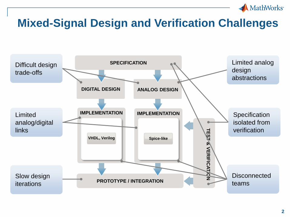
PROTOTYPE / INTEGRATION
IMPLEMENTATIONIMPLEMENTATION
ANALOG DESIGN
Mixed-Signal Design and Verification Challenges
DIGITAL DESIGN
SPECIFICATION
TE
ST
& V
ER
IFIC
AT
ION
Difficult design
trade-offs
Limited
analog/digital
links
Slow design
iterations
Specification
isolated from
verification
Limited analog
design
abstractions
Disconnected
teams
Spice-likeVHDL, Verilog
3
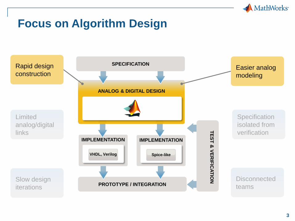
Rapid design
constructionEasier analog
modeling
Limited
analog/digital
links
Slow design
iterations
Specification
isolated from
verification
Disconnected
teamsPROTOTYPE / INTEGRATION
IMPLEMENTATIONIMPLEMENTATION
Focus on Algorithm Design
ANALOG & DIGITAL DESIGN
SPECIFICATION
Spice-likeVHDL, Verilog
TE
ST
& V
ER
IFIC
AT
ION

4
PROTOTYPE / INTEGRATION
IMPLEMENTATIONIMPLEMENTATION
Anticipate Impairments at System-Level
ANALOG & DIGITAL DESIGN
SPECIFICATION
Spice-likeVHDL, Verilog
PhysicalFixed-Point
Multi-domain
simulation
Rapid design
iterations
Rapid design
constructionEasier analog
modelingT
ES
T &
VE
RIF
ICA
TIO
N
Specification
isolated from
verification
Disconnected
teams

5
PROTOTYPE / INTEGRATION
IMPLEMENTATIONIMPLEMENTATION
Perform Continuous Verification
ANALOG & DIGITAL DESIGN
SPECIFICATION
Spice-likeVHDL, Verilog
TE
ST
& V
ER
IFIC
AT
ION
Integrated
specification
Improved team
communication
Rapid design
constructionEasier analog
modeling
Multi-domain
simulation
Rapid design
iterations
6
PROTOTYPE / INTEGRATION
IMPLEMENTATIONIMPLEMENTATION
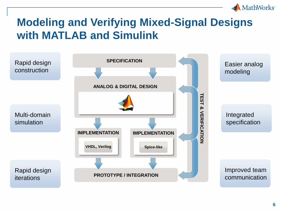
Modeling and Verifying Mixed-Signal Designs
with MATLAB and Simulink
ANALOG & DIGITAL DESIGN
SPECIFICATION
Spice-likeVHDL, Verilog
TE
ST
& V
ER
IFIC
AT
ION
Integrated
specification
Improved team
communication
Rapid design
constructionEasier analog
modeling
Multi-domain
simulation
Rapid design
iterations

7
Save >30% of Overall Development Time(and Improve Quality, Reduce Re-spins, etc.)
0 50 100 150 200 250
WithoutMathWorks
Tools
WithMathWorks
Tools
Days
Time spent in project phases
Requirements System Design Implementation Integration Testing

8
Recent Successes
Customer Use case
Atmel RF Front End for DVB
Analog-digital co-design and verification
IDT-Newave Audio chipset
Rapid simulation of PLLs
Realtek Voice-band codec
Analog-Digital design
RFMD Video transceiver
System-level/SPICE cosimulation
Fujitsu 40 Gbit/s SERDES
Rapid system simulation

9
An Integrated Environment for
Model-Based Design of Mixed-Signal Systems
Saves Time and Costly Errors
Algorithmic design with many trusted functions
► You don’t have to become a modeling guru
Anticipating implementation impairments / constraints
► Find errors early and optimize your design
Building and reusing system-verification test-benches
► The verification effort will be limited

10
Design and Verification of a
Sigma-Delta ADC

11
Goal: Preliminary Design of a Simple ADC
Sigma-delta ADC
– Which order?
– Will it be stable?
Analog input signal around 8kHz
– Design of input anti-aliasing analog filter
Design of output decimation filter
– Tradeoff cost and performances

12
Mixed-Signal Modeling with Simulink
Analog and digital in same model
Time handling
Multiple solvers / schedulers
INTEGRATION
IMPLEMENTATION
DESIGN
TE
ST
& V
ER
IFIC
AT
ION
SPECIFICATION
FPGA ASIC
VHDL, Verilog
ASIC SMPS
Spice-like
Algorithms
AnalogDigital
PhysicalFixed-Point

13
Sigma-Delta ADC with Circuit Elements
Mixed-behavioral and circuit design
Include circuit elements
Complex filter design
INTEGRATION
IMPLEMENTATION
DESIGN
TE
ST
& V
ER
IFIC
AT
ION
FPGA ASIC
VHDL, Verilog
ASIC SMPS
Spice-like
Algorithms
AnalogDigital
PhysicalFixed-Point
SPECIFICATION

14
Hardware Rapid Prototyping
On-target automatic HDL code
generation
Verification via co-simulation with
third party HDL simulators
INTEGRATION
IMPLEMENTATION
DESIGN
TE
ST
& V
ER
IFIC
AT
ION
FPGA ASIC
VHDL, Verilog
ASIC SMPS
Spice-like
Algorithms
AnalogDigital
PhysicalFixed-Point
SPECIFICATION
15
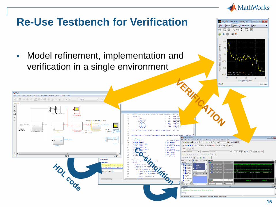
Re-Use Testbench for Verification
Model refinement, implementation and
verification in a single environment

16
An Integrated Environment for
Model-Based Design of Mixed-Signal Systems
Saves Time and Costly Errors
Algorithmic design with many trusted functions
► You don’t have to become a modeling guru
Anticipating implementation impairments / constraints
► Find errors early and optimize your design
Building and reusing system-verification test-benches
► The verification effort will be limited
17
Design and Verification of a PLL

18
Phase-Locked Loop
Feedback control system
– Generates a signal with a fixed relation to the phase of a
reference signal
– Used for frequency synthesis, synchronization
Measurements of interest
– Time: rise time, overshoot, lock time, jitter
– Frequency: phase noise, spurs
VCOPhase
Detector
Loop
Filter
1/N
Reference

19
PLL Key Components
Digital Flip-Flop Based
Phase\Frequency Detector
Analog Circuit Model
Charge Pump
Flip-flops
Delay
Memory
Basic Logic
Resistors
Capacitors
Current sources
20
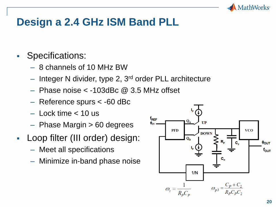
Design a 2.4 GHz ISM Band PLL
Specifications:
– 8 channels of 10 MHz BW
– Integer N divider, type 2, 3rd order PLL architecture
– Phase noise < -103dBc @ 3.5 MHz offset
– Reference spurs < -60 dBc
– Lock time < 10 us
– Phase Margin > 60 degrees
Loop filter (III order) design:
– Meet all specifications
– Minimize in-band phase noise

21
From Behavioral Model to Implementation
Start your design in MATLAB
Refine design details using behavioral circuit models
Verify the specs with the refined model
Link to circuit simulators to verify the behavioral models
Verify the performances with the refined model
Link to circuit simulators to verify the implementation

22
Design Exploration in MATLAB
Stability analysis
Step response
Noise performance
INTEGRATION
IMPLEMENTATION
DESIGN
TE
ST
& V
ER
IFIC
AT
ION
FPGA ASIC
VHDL, Verilog
ASIC SMPS
Spice-like
Algorithms
AnalogDigital
PhysicalFixed-Point
SPECIFICATION

23
Sequence of Model Elaborations
Start with a basic “Phase Domain”
linear PLL
INTEGRATION
IMPLEMENTATION
DESIGN
TE
ST
& V
ER
IFIC
AT
ION
FPGA ASIC
VHDL, Verilog
ASIC SMPS
Spice-like
Algorithms
AnalogDigital
PhysicalFixed-Point
SPECIFICATION

24
Laplace Representation vs. Circuit Elements
Progressively refine the model
and validate it using the same
testbench
INTEGRATION
IMPLEMENTATION
DESIGN
TE
ST
& V
ER
IFIC
AT
ION
FPGA ASIC
VHDL, Verilog
ASIC SMPS
Spice-like
Algorithms
AnalogDigital
PhysicalFixed-Point
SPECIFICATION

25
Converting from Phase to Time Domain
Build an accurate model for spurs
and phase-noise simulation
INTEGRATION
IMPLEMENTATION
DESIGN
TE
ST
& V
ER
IFIC
AT
ION
FPGA ASIC
VHDL, Verilog
ASIC SMPS
Spice-like
Algorithms
AnalogDigital
Fixed-Point
SPECIFICATION
Physical

26
Time Domain Model
Starting point for detailed circuit
design
INTEGRATION
IMPLEMENTATION
DESIGN
TE
ST
& V
ER
IFIC
AT
ION
FPGA ASIC
VHDL, Verilog
ASIC SMPS
Spice-like
Algorithms
AnalogDigital
Fixed-Point
SPECIFICATION
Physical

27
VERIFICATION / INTEGRATION / PROTOTYPE
IMPLEMENTATION
SPECIFICATIONS
Top-Down Design With MATLAB and SimulinkFocus on Simulation and Model Refinement at the System Level
Rapid design
construction
Easier analog
modeling
Spice-likeVHDL, Verilog
Mixed-Signal IC Design Tools
Multi-domain
simulation
Fast simulation
Fixed-point and
bit-accurate
simulation
Hardware /
Software
codesign

28
VERIFICATION / INTEGRATION / PROTOTYPE
IMPLEMENTATION
SPECIFICATIONS
Top-Down Design for ASICsIntegration with Standard EDA flows
Spice-likeVHDL, Verilog
Mixed-Signal IC Design Tools
Synthesizable
HDL code
generation
Rapid design
iterations
Analog design
gap
Slow simulation
Late verificationEarly
verification
Fixed-Point Designer, HDL Coder, HDL Verifier
What about Analog/Mixed-Signal?

29
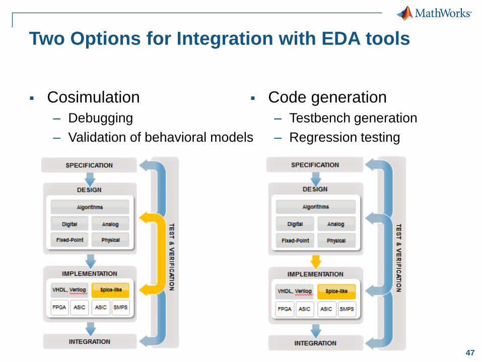
Two Options for Integration with EDA tools
Cosimulation
– Debugging
– Validation of behavioral models
Code generation
– Testbench generation
– Regression testing

30
Option 1: Cosimulation

31
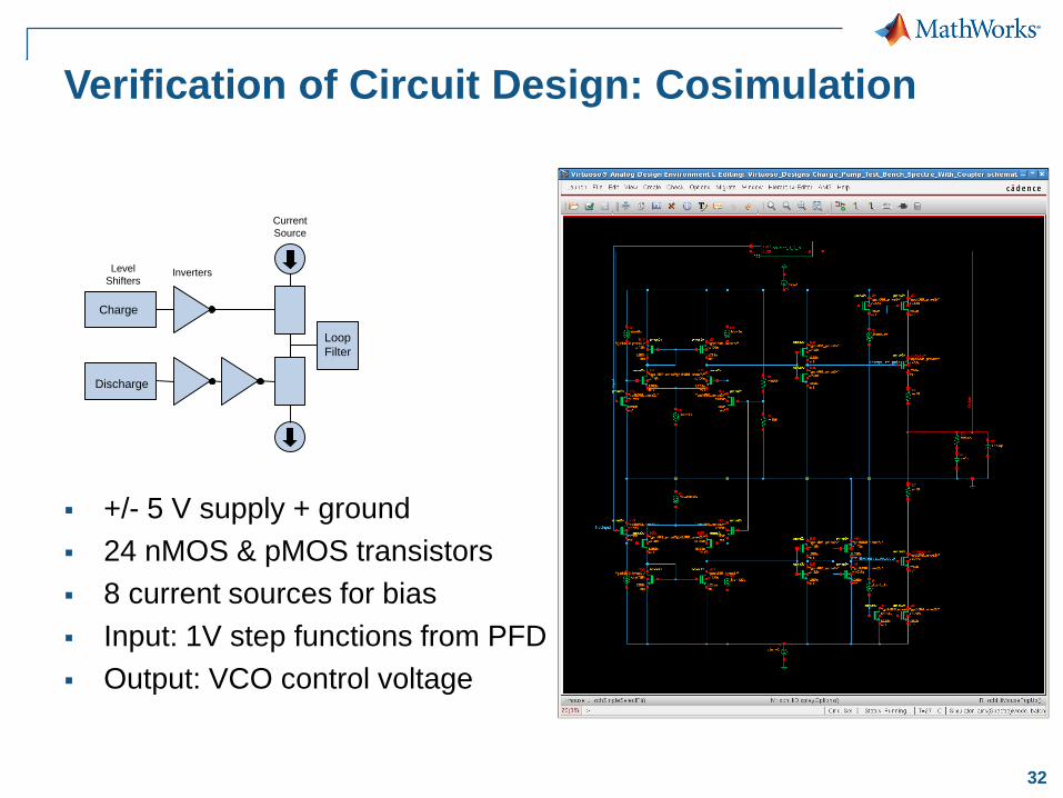
Verification of Circuit Design: Cosimulation
Verify implementation against
executable specifications
INTEGRATION
IMPLEMENTATION
DESIGN
TE
ST
& V
ER
IFIC
AT
ION
FPGA ASIC
VHDL, Verilog
ASIC SMPS
Spice-like
Algorithms
AnalogDigital
PhysicalFixed-Point
SPECIFICATION
32
Charge
Discharge
Level
ShiftersInverters
Current
Source
Loop
Filter
Verification of Circuit Design: Cosimulation
+/- 5 V supply + ground
24 nMOS & pMOS transistors
8 current sources for bias
Input: 1V step functions from PFD
Output: VCO control voltage

33
Cosimulation with Simulink
Verify transistor level design:
– within the context of a full system simulation
– using visualization and analysis capabilities of Simulink and MATLAB
– testing each module independently of other modules

34
Cosimulation Verification Workflow
Ideal behavioral model
Cosimulation
Refined model

35
Option 2: Code Generation

36
Mixed-Signal Design GapHow to Bridge Simulink and Mixed-Signal EDA Flows?
?
No standard API for analog simulators
Different analog simulators provide different results
Cosimulation can be slow
Analog synthesis is still a research topic

37
Using C Code Generation and DPI-C Interface
1. Make your Simulink model C code generation compliant
2. Generate C code from your Simulink model
3. Automatically wrap the C code using SystemVerilog
DPI-C interface
4. Import, build and simulate the equivalent behavioral
SystemVerilog model in your IC design tool
2. SystemVerilog wrapper
1. C Code3. IC Design Tool

38
Benefits of C Code Generation and DPI-C Export
Fast simulation using the native SystemVerilog API
IC design tool independent
Customizable approach supported by MathWorks
Leverages mature C code generation technology
Most suitable for testbench generation and IC verification
Support discrete and continuous time signals
Simulink
IC Design Tool

39
Some Details …

40
Mixed-Signal PLL Model
Binary Signal
Source
Phase / Frequency
Detector
(digital)
Charge Pump + Loop
filter (analog)
Divider
(triggered block)
VCO
(analog)
41
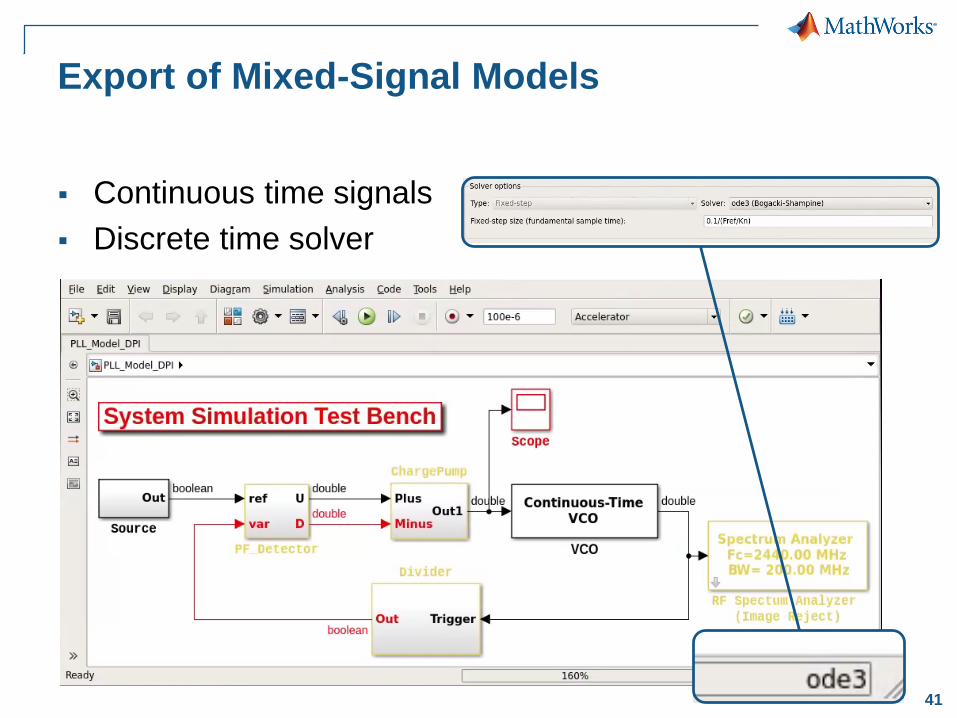
Export of Mixed-Signal Models
Continuous time signals
Discrete time solver

42
From Variable to Fixed Time Step Solver
Chose a fixed sample time that it is small enough to
give correct results
Tradeoff accuracy and simulation time
Large time step Small time step

43
Schedule the Execution of
SystemVerilog Modules
Simulink handles multi-rate systems automatically
You need to define a scheduler to control the
SystemVerilog execution
Slow Clock

44
SystemVerilog Discretizes Time
Discrete sample times in Simulink are integer multiple
of an arbitrary fundamental sample time
In SystemVerilog all sample times are integer multiple
of 1fs (or a reference discrete sample time)

45
Certified by STARC
http://www.mathworks.com/company/newsletters/articles/a-next-generation-workflow-for-system-level-design-of-mixed-signal-integrated-circuits.html

46
STARC: Semiconductor Technology Academic Research Center
Members: Fujitsu Semiconductor, Renesas, ROHM, Sony, Toshiba
Key Takeaways – Reference Motif Circuit (Sigma-Delta Converter)
• Circuit Level – Two Months
• Verilog-AMS – Six Days
• STARCAD-AMS (MathWorks) – Three Days
Several semiconductor companies adopting STARC recommendation
• Japan member companies
• Non-member AMER/EMEA semiconductor majors
http://www.mathworks.com/company/newsletters/articles/a-next-generation-workflow-for-system-level-design-of-mixed-signal-integrated-circuits.html
47
Two Options for Integration with EDA tools
Cosimulation
– Debugging
– Validation of behavioral models
Code generation
– Testbench generation
– Regression testing

48
Mixed-Signal Verification:
Reuse System Level Testbenches in IC Design Tools
Two complementary verification approaches using
Simulink system-level testbenches
► You don’t have to become a modeling guru
Cosimulation
► Find errors early and optimize your design
Code generation
► The verification effort will be limited

49
Next Steps

50
Explore Mixed-Signal Design
with MATLAB and Simulink
http://www.mathworks.com/mixed-signal-systems/

51
Browse Videos, Webinars, Articles

52
Download and Try Mixed-Signal Library
Direct Link: https://www.mathworks.com/programs/mixed-signal/index.html

53
Request Onsite Meeting and Discussion
Discuss your project and workflow with MathWorks
Applications Engineering Team
Digital: HDL code generation, verification
– Connectivity to Mentor, Cadence, and Synopsys flows
Analog: Verilog-A or SystemVerilog code generation
– C code with DPI-C wrappers
– Connectivity to Cadence and Synopsys flows
IBIS-AMI component creation from MATLAB and
Simulink

54
PROTOTYPE / INTEGRATION
IMPLEMENTATIONIMPLEMENTATION
Modeling and Verifying Mixed-Signal Designs
with MATLAB and Simulink
ANALOG & DIGITAL DESIGN
SPECIFICATION
Spice-likeVHDL, Verilog
TE
ST
& V
ER
IFIC
AT
ION
Integrated
specification
Improved team
communication
Rapid design
constructionEasier analog
modeling
Multi-domain
simulation
Rapid design
iterations