Embed Size (px)
Citation preview

ETNAKent State University and
Johann Radon Institute (RICAM)
Electronic Transactions on Numerical Analysis.Volume 54, pp. 1–30, 2021.Copyright c© 2021, Kent State University.ISSN 1068–9613.DOI: 10.1553/etna_vol54s1
MODELING AND DISCRETIZATION METHODS FOR THE NUMERICALSIMULATION OF ELASTIC FRAME STRUCTURES∗
LUKA GRUBIŠIC†, MATKO LJULJ†, VOLKER MEHRMANN‡, AND JOSIP TAMBACA†
Abstract. A new model description for the numerical simulation of elastic frame structures is proposed. Insteadof resolving algebraic constraints at frame nodes and incorporating them into the finite element spaces, the constraintsare included explicitly in the model via new variables and enforced via Lagrange multipliers. Based on the newformulation, an inf-sup inequality for the continuous-time formulation and the finite element discretization is proved.Despite the increased number of variables in the model and the discretization, the new formulation leads to fastersimulations for the stationary problem and simplifies the analysis and the numerical solution of the evolution problemdescribing the movement of the frame structure under external forces. The results are illustrated via numericalexamples for the modeling and simulation of elastic stents.
Key words. elastic frame structure, elastic stent, mathematical modeling, numerical simulation, mixed finiteelement formulation, inf-sup condition, stationary system, evolution equation
AMS subject classifications. 74S05, 74K10, 74K30, 74G15, 74H15, 65M15, 65M60
1. Introduction. Motivated by the modeling and simulation of elastic stents, in thispaper we present a new model class for the dynamic and stationary simulation of elasticframe structures. It uses constrained partial differential equations in mixed variational weakform, which model an elastic frame structure consisting of one-dimensional curved elasticrods. The problem has already been considered in [20] and [22], where the inextensibilityand unshearability of the rods were expressed in the mixed weak formulation, while thecontinuity of the displacement and the infinitesimal rotations were described via constraints inthe nodes of the network expressed implicitly in the function space. In contrast to this, in ourextended model presented here, these constraints are explicitly added to the system model,and, similarly as in the mortar finite element approach [42], they are enforced via Lagrangemultipliers in the analysis and simulation. This extension requires the introduction of newunknowns at the vertices where different rods are connected as well as further unknowns forthe contact conditions and contact forces at the end points of each rod. The advantage of thisextended model is that the constraints do not have to be incorporated in the function spaces asis typically the case; see, e.g., the approach in [20]. This simplifies the analysis of the systemof constrained partial differential equations, in particular in proving an inf-sup inequalitywhich directly transfers to a discrete inf-sup inequality in the discretized setting. Based onthese results we retrace the steps of the standard error analysis from [4]. The results that weprove for the continuous model in Section 4 hold for general geometries, while the results forthe discrete approximation in Section 5 are proved only for geometries with straight rods.
Despite the introduction of many new unknowns, we will also demonstrate with numericalexamples that when the model is sufficiently refined, even the numerical solvers become moreefficient than those for the classical approach.
∗Received December 25, 2018. Accepted September 8, 2020. Published online on October 30, 2020. Recom-mended by M. Benzi. This work has been supported by Deutscher Akademischer Austauschdienst (DAAD) via ProjectAsymptotic and algebraic analysis of nonlinear eigenvalue problems in contact mechanics and electro magnetism. Thethird author is also supported by Einstein Foundation Berlin via Einstein Center ECMath Project: Model Reductionfor Nonlinear Parameter-Dependent Eigenvalue Problems in Photonic Crystals.†Department of Mathematics, Faculty of Science, University of Zagreb, Bijenicka 30, 10000 Zagreb
(luka,mljulj,[email protected]).‡Institut für Mathematik MA 4-5, TU Berlin, Str. des 17. Juni 136, D-10623 Berlin, FRG
1

ETNAKent State University and
Johann Radon Institute (RICAM)
2 L. GRUBIŠIC, M. LJULJ, V. MEHRMANN, AND J. TAMBACA
Examples of structural problems posed on a network structures include metallic framestructures such as bridges and buildings in civil engineering [24, 37], carbon nanotubes [43],tissue scaffolds in biomaterial engineering [28], and cytoskeletons in cell biology [7]. Some-what different in nature are networks of highways [13, 18] and arterial networks [16] (sinceone direction is preferred). Various models of multiple-link flexible structures consisting offinitely many interconnected flexible elements such as strings, beams, or plates have beengiven recently; see, for instance, [5, 9, 14, 29, 32, 34, 38] and the references therein. However,the problems considered in these models are not appropriate in our situation since the geometryof the stent cannot be described by straight beams or ones that are embedded in a plane.
The modeling of elastic structures on the basis of Cosserat theory [10] with deformationsin three-dimensional space is well established; see [1, 8, 39]. In this paper we discuss thecase of an elastic frame or network of elastic rods. Our main motivation is the modelingand simulation of elastic stents as, e.g., the one in Figure 1.1. In recent years, elastic frame
FIG. 1.1. Example of an elastic stent (Cypher stent by Cordis Corporation).
structures such as stents are modeled as a union of 1D curved rods (see [25, 26]) and a set ofjunction conditions describing the connection of the rods; see [19] for the derivation of themodel. The resulting model describes the three-dimensional behavior of the frame structure,but it has the complexity of a one-dimensional model. For the application to elastic stents, thismodeling approach was first introduced in [41] and then reformulated in weak form in [11].Properties of the mixed formulation for the model were analyzed in [20], numerical methodswere introduced and error estimates derived in [22], but up to now, error estimates for thecontact forces were missing.
The main result of this paper is the construction of an extended description of elasticframe structures that includes all constraints for the displacements and forces. The paperis organized as follows. In Section 2 we discuss the previous modeling approach, and inSection 3 we present the extended model formulation. In Section 4 we analyze the new modelclass and give a proof of the inf-sup inequality for the weak formulation of the continuousinfinite-dimensional model, and in Section 5 we analyze the discrete model that is obtainedafter finite element discretization, and we show a corresponding inf-sup inequality. Finally,in Section 6 we study the dynamical system of the movement under excitation forces. Weanalyze the properties and present numerical simulation results.
2. Modeling elastic frame structures. To model the topology of a frame model ofconnected elastic rods, following [25, 26], we use an undirected graph N = (V, E) consistingof a set V of nV vertices, which are the points where the middle lines of the rods meet, and aset E of nE edges that represent a 1D description of the curved rod. To be able to use a 1Dcurved rod model, we additionally need to prescribe the local geometry of the rod, i.e., themiddle curve and the geometry of the cross-section as well as the material properties of therods. These are given by
• the function Φi : [0, `i]→ R3 as a natural parametrization of the middle line of theith rod of length `i represented by the edge ei ∈ E ,
• the shear modulus µi and the Young modulusEi as parameters describing the materialof the ith rod,

ETNAKent State University and
Johann Radon Institute (RICAM)
NUMERICAL SIMULATION OF ELASTIC FRAME STRUCTURES 3
• as well as the width wi and the thickness ti of the rectangular cross-section of the ithrod.
Using these quantities, in the stationary case (see, e.g., [41]) of the stent models, the equationsfor the ith rod ei ∈ E are given by the following system of ordinary differential equations (inspace)
0 = ∂spi + f i,(2.1)
0 = ∂sqi + ti × pi,(2.2)
0 = ∂sωi −Qi(Hi)−1(Qi)Tqi,(2.3)
0 = ∂sui + ti × ωi,(2.4)
where for the ith rod• ui : [0, `i]→ R3 denotes the vector of displacements on the middle curve,• ωi : [0, `i]→ R3 is the vector of infinitesimal rotations of the cross-section,• qi is the contact moment and pi is the contact force,• f i is the line density of the applied forces,• Qi = [ti,ni, bi] is an orthogonal rotation matrix associated to the middle curve
with ti = (Φi)′ being the unit tangent to the middle curve and ni, bi being vectorsspanning the normal plane to the middle curve so that Qi represents the local basis ateach point of the middle curve,
• Hi = diag(µiKi, EiIin, EiIib) is a positive definite diagonal matrix with the Young
modulus Ei, the shear modulus µi, Iin, Iib are the moments of inertia of the crosssection, and µiKi is the torsional rigidity of the cross section.
Equations (2.1) and (2.2) represent equilibrium equations (for forces and moments), while (2.3)and (2.4) are constitutive relations. In particular, (2.4) describes the inextensibility andunshearability of the struts; see [11] for more details in the case of stent models.
In addition to equations (2.1)–(2.4), at each vertex of the network structure we have thekinematic coupling condition that u and ω are continuous and a dynamic coupling conditiondescribing the balance of contact forces p and contact moments q.
We denote by J−j the set of all edges that leave the jth vertex, i.e., the local variable isequal to 0 at the vertex j, and by J+
j the set of all edges that enter the vertex, i.e., the localvariable is equal to `i for the ith edge at the vertex j. Using these notations we obtain the nodeconditions
ωi(0) = ωk(`k), i ∈ J−j , k ∈ J+j , j = 1, . . . , nV ,
ui(0) = uk(`k), i ∈ J−j , k ∈ J+j , j = 1, . . . , nV ,∑
i∈J+j
pi(`i)−∑i∈J−j
pi(0) = 0, j = 1, . . . , nV ,
∑i∈J+
j
qi(`i)−∑i∈J−j
qi(0) = 0, j = 1, . . . , nV .
Since this is a pure traction problem, we can integrate over s ∈ [0, `i] and specify a uniquesolution by requiring the two additional conditions
(2.5)∫Nu :=
nV∑i=1
∫ `i
0
ui ds = 0,
∫Nω :=
nV∑i=1
∫ `i
0
ωi ds = 0,
which means that the total displacement as well as the total infinitesimal rotation are zero.

ETNAKent State University and
Johann Radon Institute (RICAM)
4 L. GRUBIŠIC, M. LJULJ, V. MEHRMANN, AND J. TAMBACA
The model is then described by the collection of all displacements ui and infinitesimalrotations ωi for all edges, which both are continuous on the whole network. Thus, the tuples ofunknowns in the problem uS = ((u1,ω1), . . . , (unE ,ωnE )) belong to the space H1(N ;R6),where
H1(N ;Rk) =
(y1, . . . ,ynE ) ∈
nE∏i=1
H1(0, `i;Rk) :
yi(0) = yk(`k), i ∈ J−j , k ∈ J+j , j = 1, . . . , nV
,
with H1(0, `i;Rk) being the Sobolev space of functions on [0, `i] whose derivatives up to firstorder are square Lebesgue integrable. In [20], for the application of stents, a mixed formulationof such a model is presented with Lagrange multipliers appearing in the formulation due tothe inextensibility and unshearability of the rods in the 1D curved rod model (2.4) and the twoconditions for the total displacement and infinitesimal rotation (2.5).
Let AI ∈ R3nV ,3nE denote the incidence matrix of the oriented graph (V, E) withthree connected components organized in the following way: a 3 × 3 submatrix at rows3i− 2, 3i− 1, 3i and columns 3j − 2, 3j − 1, 3j is I3 if the edge j enters the vertex i, −I3 ifit leaves the vertex i, or 0 otherwise. Then the matrix A+
I is obtained from AI by setting allelements −1 to 0, and A−I is defined as AI = A+
I −A−I . Let us also introduce the projectors
PiE ∈ R3,3nE , Pj
V ∈ R3,3nV
on the coordinates 3i− 2, 3i− 1, 3i and 3j − 2, 3j − 1, 3j, respectively. We will also needthe spaces
L2(N ;R3) =
nE⊗i=1
L2(0, `i;R3), L2Hr (N ;R3) =
nE⊗i=1
Hr(0, `i;R3), r ≥ 1,
with associated norms
‖(y1, . . . ,ynE )‖L2(N ;R3) =
(nE∑i=1
‖yi‖2L2(0,`i;R3)
)1/2
,
‖(y1, . . . ,ynE )‖L2Hr (N ;R3) =
(nE∑i=1
‖yi‖2Hr(0,`i;R3)
)1/2
.
The norm corresponding to the last term for r = 1 is also used as the norm forH1(N ;R6). Fora function y = (y1, . . . ,ynE )∈L2
H1(N ;R3), we denote by y′ the vector (∂sy1, . . . , ∂sy
nE )∈L2(N ;R3).
3. Extended model formulation. In this section we extend the standard modeling ap-proach in a way that enables us to prove a discrete inf-sup inequality, and thus, using classicalresults, error estimates follow. For this, we include all unknowns in the problem explicitlyso that not only the inextensibility and unshearability of the rod is expressed in the weakformulation, but the continuity of the displacement and infinitesimal rotation is also reflectedin the function space of the mixed formulation in H1(N ;R6). This leads to the introductionof new unknowns; these are the displacements and infinitesimal rotations at the vertices, andfurther, the contact moments and contact forces at the ends of each rod.

ETNAKent State University and
Johann Radon Institute (RICAM)
NUMERICAL SIMULATION OF ELASTIC FRAME STRUCTURES 5
Since u and ω are continuous on the whole elastic frame, we introduce as extra variablesthe displacements and infinitesimal rotations at the vertices U i,Ωi, i = 1, . . . , nV , and thenform the vectors
U = [U1, . . . ,UnV ]T , Ω = [Ω1, . . . ,ΩnV ]T .
The kinematic coupling at the vertex j leads to the conditions
ui(`i) = U j , i ∈ J+j , ui(0) = U j , i ∈ J−j ,
ωi(`i) = Ωj , i ∈ J+j , ωi(0) = Ωj , i ∈ J−j .
(3.1)
To express the dynamic coupling conditions, we introduce the contact moments and forces atthe ends of the struts,
(3.2) Qi+ = qi(`i), Qi
− = qi(0), P i+ = pi(`i), P i
− = pi(0), i = 1, . . . , nE ,
and define
P± = (P 1±, . . . ,P
nE± ), Q± = (Q1
±, . . . ,QnE± ).
The dynamic coupling conditions at vertex j can then be expressed as
(3.3)∑i∈J+
j
P i+ −
∑i∈J−j
P i− = 0,
∑i∈J+
j
Qi+ −
∑i∈J−j
Qi− = 0, j = 1, . . . , nE .
Equations (2.1)–(2.4), (3.1), (3.2), (3.3), and (2.5) together constitute the elastic frame problemin our extended formulation, for which we now derive the weak formulation in detail.
We multiply the ith equation of (2.1) by vi ∈ H1(0, `i;R3) and that of (2.2) bywi ∈ H1(0, `i;R3), add them, integrate over s ∈ [0, `i], and sum the equations over i. Thisyields
0 =
nE∑i=1
∫ `i
0
∂spi · vi + f i · vi + ∂sq
i ·wi + ti × pi ·wi ds.
After partial integration we obtain
0 =
nE∑i=1
∫ `i
0
(−pi · ∂svi + f i · vi − qi · ∂swi−ti ×wi · pi
)ds+ pi · vi
∣∣`i0
+ qi ·wi∣∣`i0,
i.e.,
nE∑i=1
∫ `i
0
(−pi · (∂svi + ti ×wi)− qi · ∂swi
)ds
+ P i+ · vi(`i)− P
i− · vi(0)
+Qi+ ·wi(`i)−Qi
− ·wi(0) = −nE∑i=1
∫ `i
0
f i · vi ds.
(3.4)
In a similar way we multiply (2.3) by ξi ∈ L2(0, `i;R3) and (2.4) by θi ∈ L2(0, `i;R3),integrate over s ∈ [0, `i], and sum all equations to obtain
(3.5) 0 =
nE∑i=1
∫ `i
0
−∂sωi · ξi + Qi(Hi)−1(Qi)Tqi · ξi − (∂sui + ti × ωi) · θi ds.
ETNAKent State University and
Johann Radon Institute (RICAM)
6 L. GRUBIŠIC, M. LJULJ, V. MEHRMANN, AND J. TAMBACA
We also multiply the equations in (3.3) for the jth vertex by V j andW j from R3, respectively,and sum the equations over j, which gives
nV∑j=1
∑i∈J+
j
P i+ −
∑i∈J−j
P i−
· V j +
nV∑j=1
∑i∈J+
j
Qi+ −
∑i∈J−j
Qi−
·W j = 0.
Since∑
i∈J+jP i
+ = PjVA+IP+ and
∑i∈J−j
P i− = Pj
VA−I P−, this equation can be writtenas
nV∑j=1
PjV(A+IP+ −A−I P−
)· V j +
nV∑j=1
PjV(A+IQ+ −A−IQ−
)·W j = 0,
and therefore,
(3.6)(A+IP+ −A−I P−
)· V +
(A+IQ+ −A−IQ−
)·W = 0
for all V = [V 1, . . . ,V nV ]T ,W = [W 1, . . . ,W nV ]T ∈ R3nV .Multiplying the equations for the displacements in (3.1) by Θi
+ and Θi−, we obtain
ui(`i) ·Θi+ = U j ·Θi
+, i ∈ J+j , ui(0) ·Θi
− = U j ·Θi−, i ∈ J−j .
Since PiE(A
+I )TU = U j for i ∈ J+
j , for Θ± = [Θ1±, . . . ,Θ
nE± ]T , we have
nE∑i=1
ui(`i)·Θi+ = (A+
I )TU ·Θ+,
nE∑i=1
ui(0)·Θi− = (A−I )TU ·Θ−, Θ+,Θ− ∈ R3nE ,
and similarly, for the rotations, using the notation Ξ± = [Ξ1±, . . . ,Ξ
nE± ]T , we get
nE∑i=1
ωi(`i) ·Ξi+ = (A+
I )TΩ ·Ξ+,
nE∑i=1
ωi(0) ·Ξi− = (A−I )TΩ ·Ξ−, Ξ+,Ξ− ∈ R3nE .
Thus, we have
nE∑i=1
(ui(`i) ·Θi+ − ui(0) ·Θi
−)− (A+I )TU ·Θ+ + (A−I )TU ·Θ− = 0,
Θ+,Θ− ∈ R3nE ,
(3.7)
for the displacements and
nE∑i=1
(ωi(`i) ·Ξi+ − ωi(0) ·Ξi
−)− (A+I )TΩ ·Ξ+ + (A−I )TΩ ·Ξ− = 0,
Ξ+,Ξ− ∈ R3nE ,
(3.8)
for the rotations. We multiply equations (2.5) by α and β, respectively, and sum up to obtain
(3.9) α ·∫Nu+ β ·
∫Nω = 0, α,β ∈ R3.

ETNAKent State University and
Johann Radon Institute (RICAM)
NUMERICAL SIMULATION OF ELASTIC FRAME STRUCTURES 7
Subtracting (3.6) from (3.4) gives
nE∑i=1
∫ `i
0
(−pi · (∂svi + ti ×wi)− qi · ∂swi
)ds
+
nE∑i=1
(P i+ · vi(`i)− P
i− · vi(0)) +
nE∑i=1
(Qi+ ·wi(`i)−Qi
− ·wi(0))
−(A+IP+ −A−I P−
)· V
−(A+IQ+ −A−IQ−
)·W = −
nE∑i=1
∫ `i
0
f i · vi ds,
vi,wi ∈ H1(0, `i;R3), i = 1, . . . , nE , V ,W ∈ R3nV .
(3.10)
We then add (3.7) and (3.8) to (3.5) and obtain
nE∑i=1
∫ `i
0
Qi(Hi)−1(Qi)Tqi · ξi − (∂sui + ti × ωi) · θi − ∂sωi · ξi ds
+
nE∑i=1
(ui(`i) ·Θi+ − ui(0) ·Θi
−) +
nE∑i=1
(ωi(`i) ·Ξi+ − ωi(0) ·Ξi
−)
− ((A+I )TU ·Θ+ − (A−I )TU ·Θ−)
− ((A+I )TΩ ·Ξ+ − (A−I )TΩ ·Ξ−) = 0,
ξi,θi ∈ L2(0, `i;R3), i = 1, . . . , nE , Θ±,Ξ± ∈ R3nE .
(3.11)
In [20] and [22], for the stent model, such a mixed formulation was presented usingthe space H1(N ;R3) for the displacement vector u and the infinitesimal rotation vector ω.The space L2(N ;R3) × R3 × R3 was used for the Lagrange multipliers p,α,β. However,the continuity conditions for the displacements and infinitesimal rotations were resolved andinherently built into the space H1(N ;R3). We now relax these conditions and consider themas additional equations for the problem and extend the space of unknowns further by addingLagrange multipliers for these extra constraints. The resulting function spaces are given by
V = L2(N ;R3)× L2(N ;R3)× R3nE × R3nE × R3nE × R3nE × R3 × R3,
M = L2H1(N ;R3)× L2
H1(N ;R3)× R3nV × R3nV .
To simplify the notation for the elements of these spaces, we introduce
Σ := (q,p,P+,P−,Q+,Q−,α,β) ∈ V, φ := (u,ω,U ,Ω) ∈M
for the unknowns in the problem and
Γ := (ξ,θ,Θ+,Θ−,Ξ+,Ξ−,γ, δ) ∈ V, ψ := (v,w,V ,W ) ∈M
for the associated test functions.

ETNAKent State University and
Johann Radon Institute (RICAM)
8 L. GRUBIŠIC, M. LJULJ, V. MEHRMANN, AND J. TAMBACA
In this notation, the bilinear forms and the linear functionals that appear in the abovecalculations are given by
a : V × V → R, b : V ×M → R, f : M → R,
a(Σ,Γ) :=
nE∑i=1
∫ `i
0
Qi(Hi)−1(Qi)Tqi · ξi ds,
b(Σ,ψ) :=
nE∑i=1
∫ `i
0
(−pi · (∂svi + ti ×wi)− qi · ∂swi
)ds
+
nE∑i=1
(P i+ · vi(`i)− P
i− · vi(0))
+
nE∑i=1
(Qi+ ·wi(`i)−Qi
− ·wi(0))
−(A+IP+ −A−I P−
)· V
−(A+IQ+ −A−IQ−
)·W +α ·
∫Nv + β ·
∫Nw,
f(ψ) := −nE∑i=1
∫ `i
0
f i · vi ds.
Then the variational formulation (3.10), (3.11), and (3.9) can be expressed as follows:Determine Σ ∈ V and φ ∈M such that
(3.12)a(Σ,Γ) + b(Γ,φ) = 0, Γ ∈ V,b(Σ,ψ) = f(ψ), ψ ∈M.
In this way we have obtained that the solution of the problem in (2.1)–(2.5) satisfies (3.12)and conversely that any solution of (3.12) satisfies (2.1)–(2.5).
In this section we have extended the mathematical formulation of an elastic frame structureby including the continuity conditions at the nodes as extra equations and by adding furtherLagrange multipliers. In the next sections, we will use this formulation to obtain a discreteinf-sup inequality and to present a simple proof of the continuous inf-sup inequality.
4. Properties of the continuous model. In this section we consider the properties of thecontinuous operator equation (3.12). For the operator B : V →M ′ defined by
M ′〈BΣ,ψ〉M = b(Σ,ψ), ψ ∈M,
we have the adjoint operator BT : M → V ′ (we use the matrix notation to illustrate thesimilarity to the discrete case discussed later), which satisfies
V 〈Σ, BTψ〉V ′ = b(Σ,ψ), Σ ∈ V.
Then KerBT , the kernel ofBT , is defined as the set of vector functionsψ = (v,w,V ,W ) ∈M such that
b(Σ,ψ) = 0, Σ ∈ V,

ETNAKent State University and
Johann Radon Institute (RICAM)
NUMERICAL SIMULATION OF ELASTIC FRAME STRUCTURES 9
so that ψ = (v,w,V ,W ) ∈ KerBT if and only if
∂svi + ti ×wi = 0, ∂sw
i = 0, i = 1, . . . , nE ,(4.1) ∫Nv =
∫Nw = 0,(4.2)
vi(`i) = PiE(A
+I )TV , vi(0) = Pi
E(A−I )TV , i = 1, . . . , nE ,(4.3)
wi(`i) = PiE(A
+I )TW , wi(0) = Pi
E(A−I )TW , i = 1, . . . , nE .(4.4)
Conditions (4.3) and (4.4) imply that v andw are continuous on the complete elastic framestructure, i.e., v,w ∈ H1(N ;R3). The conditions in (4.1) imply then that w is constant onthe complete structure, and from (4.2) we obtain w = 0. Analogously, from (4.1) we obtainthat v = 0, and hence V = W = 0. Thus, we have proved the following lemma.
LEMMA 4.1. KerBT = 0.As a next step we prove that ImBT is closed. For this we derive a kind of Poincaré
inequality on the graph N using the notation v(`) = [v1(`1), . . . ,vnE (`nE )]T .LEMMA 4.2. There exists a constant C > 0 such that for all v ∈ L2
H1(N ;R3) and allV ∈ R3nV the following inequality holds:
(4.5)‖v‖L2(N ;R3) ≤ C
(‖v′‖2L2(N ;R3) +
(∫Nv
)2
+(v(0)− (A−I )TV
)2+(v(`)− (A+
I )TV)2)1/2
.
Proof. Assume the contrary, i.e., for all constants C > 0 there exist vC ∈ L2H1(N ;R3)
and V C ∈ R3nV such that the opposite inequality holds. Then, for C = 1/k, k ∈ N, thereexist sequences vk ∈ L2
H1(N ;R3) and V k ∈ R3nV such that
‖vk‖L2(N ;R3) = 1,
‖v′k‖2L2(N ;R3) +
(∫Nvk
)2
+(vk(0)− (A−I )TV k
)2+(vk(`)− (A+
I )TV k
)2 → 0,
where, as before, v′k denotes the vector of partial derivatives of vk. Thus, taking an appropriatesubsequence (still indexed by k), we have
vk v weakly in L2(N ;R3),
v′k → 0 strongly in L2(N ;R3),∫Nvk → 0,
vk(0)− (A−I )TV k → 0,(4.6)
vk(`)− (A+I )TV k → 0.(4.7)
It follows that on each elastic rod we have
vik vi weakly in L2(0, `i;R3), ∂svik → 0 strongly in L2(0, `i;R3), i = 1, . . . , nE ,
so that vi is constant on the ith rod and
vik vi weakly in H1(0, `i;R3).

ETNAKent State University and
Johann Radon Institute (RICAM)
10 L. GRUBIŠIC, M. LJULJ, V. MEHRMANN, AND J. TAMBACA
By the trace theorem (see, e.g., [15, Section 5.5, Theorem 1]), we then have
vik(0)→ vi, vik(`i)→ vi.
Using (4.6) and (4.7), we have
(4.8) PiE(A
−I )TV k → vi, Pi
E(A+I )TV k → vi, i = 1, . . . , nE .
Since in every block row of size 3, the matrices (A−I )T and (A+I )T have exactly one identity
matrix of size 3, we have that V k is convergent as well. We denote the limit by V andhave that its values are given by vi suitably organized. Therefore, since AI = A+
I −A−I ,subtracting the sequences in (4.8) we obtain that
ATIV = 0.
Since the rank of ATI is equal to 3nV−3, the kernel of AT
I is of dimension 3 by the rank-nullitytheorem [2]. We easily inspect that Ker AT
I is spanned by the vectors
(e1, e1, . . . , e1), (e2, e2, . . . , e2), (e3, e3, . . . , e3).
We therefore obtain that all vi are equal. Since 0 =∫N v =
∑nEi=1 `
ivi, we obtain that vi = 0and hence V = 0, which also implies that v = 0. Thus, since
vik(x) = vik(0) +
∫ x
0
∂svik(s) ds,
(vik)k tends to 0 strongly in L2(0, `i;R3) for all i = 1, . . . , nE , which is in contradiction tothe unit norm assumption of the sequence, i.e., ‖vk‖L2(N ;R3) = 1.
LEMMA 4.3. ImBT is closed.Proof. Consider a convergent sequence in ImBT , i.e., a sequence of the form
∂svik + ti ×wi
k → pi, ∂swik → qi, strongly in L2(0, `i;R3), i = 1, . . . , nE ,∫
Nvk → α,
∫Nwk → β,
vik(`i)− PiE(A
+I )TV k → P i
+, vik(0)− PiE(A
−I )TV k → P i
−, i = 1, . . . , nE ,
wik(`i)− Pi
E(A+I )TW k → Qi
+, wik(0)− Pi
E(A−I )TW k → Qi
−, i = 1, . . . , nE .
Applying inequality (4.5) to the sequenceswk =(w1k, . . . ,w
nEk ) andW k =(W 1
k, . . . ,WnEk )
implies that wk is bounded in L2(N ,R3). Therefore, wik is bounded in H1(0, `i;R3), and
hence there exists a subsequence and a function wi ∈ H1(0, `i;R3) such that
wikl wi weakly in H1(0, `i;R3), i = 1, . . . , nE .
We collect the limits in w = (w1, . . . ,wnE ) and, using again the trace theorem, we obtainthat
qi = ∂swi, −Pi
E(A+I )TW kl
→ Qi+ −wi(`i), −Pi
E(A−I )TW kl
→ Qi− −wi(0),
for i = 1, . . . , nE , and
β =
∫Nw.

ETNAKent State University and
Johann Radon Institute (RICAM)
NUMERICAL SIMULATION OF ELASTIC FRAME STRUCTURES 11
Since in each block row of dimension 3 the matrices A±I have exactly one identity matrix, weobtain thatW kl
converges toW , which satisfies
−PiE(A
+I )TW = Qi
+ −wi(`i), −PiE(A
−I )TW = Qi
− −wi(0), i = 1, . . . , nE .
By inequality (4.5), there is a unique function w that satisfies the associated homogeneoussystem
∂swi = 0, i = 1, . . . , nE ,
∫Nw = 0, v(0)− (A−I )TV = v(`)− (A+
I )TV = 0.
Therefore, w is unique, and thus the whole sequences (wk)k and (W k)k are convergent.An application of Lemma 4.2 to wk −w and W k −W implies that wk → w strongly inL2H1(N ;R3). Once we have established this convergence, we apply it to the term ti ×wi
k,and by the same reasoning we identify all limits related to vk and V k. We obtain vk → vstrongly in L2
H1(N ;R3) and V k → V in R3nV and that
∂svi + ti ×wi = pi, vi(`i)− Pi
E(A+I )TV = P i
+,
vi(0)− PiE(A
−I )TV = P i
−, α =
∫Nu.
Thus, Σ = (q,p,P+,P−,Q+,Q−,α,β) belongs to ImBT , and hence ImBT is closed.
As a direct consequence of Lemmas 4.1, 4.3, and [6, Proposition 1.2, page 39], we obtainthe following corollary.
COROLLARY 4.4 (Continuous inf-sup inequality). Consider the variational formulationof the model (3.12). Then there exists a constant kc > 0 such that
infψ∈M
supΣ∈V
b(Σ,ψ)
‖Σ‖V ‖ψ‖M≥ kc.
As our next result we will prove the KerB-ellipticity of the form a, i.e., that there exist ca > 0such that
a(Σ,Σ) ≥ ca‖Σ‖2V , Σ ∈ KerB.
To obtain this result, we need to restrict the class of networks that we consider.LEMMA 4.5. Let the geometry of the frame structure be such that∑
i∈J+j
ith edge is straight
αiti −
∑i∈J−
jith edge is straight
αiti = 0, j = 1, . . . , nV ,
implies that αi = 0 for all straight edges i. Then, the bilinear form a from the variationalformulation (3.12) is KerB-elliptic.
Proof. The space KerB is given by the set of Σ = (q,p,P+,P−,Q+,Q−,α,β) ∈ Vsuch that
b(Σ,ψ) = 0, ψ ∈M.

ETNAKent State University and
Johann Radon Institute (RICAM)
12 L. GRUBIŠIC, M. LJULJ, V. MEHRMANN, AND J. TAMBACA
Thus, from the definition of the form b, one has that for all ψ = (v,w,V ,W ) ∈MnE∑i=1
∫ `i
0
(−pi · (∂svi + ti ×wi)− qi · ∂swi
)ds
+
nE∑i=1
(P i+ · vi(`i)− P
i− · vi(0)) +
nE∑i=1
(Qi+ ·wi(`i)−Qi
− ·wi(0))
−(A+IP+ −A−I P−
)· V
−(A+IQ+ −A−IQ−
)·W +α ·
∫Nv + β ·
∫Nw = 0.
(4.9)
Since V andW in RnV are arbitrary, we obtain
(4.10) A+IP+ −A−I P− = A+
IQ+ −A−IQ− = 0,
which is equivalent to (3.3). These conditions mean that at each vertex, the sum of the contactforces as well as the sum of the contact moments are zero. Then, for γ ∈ R3, we insert vi = γ,wi = 0,W = V = 0 as test functions into (4.9) and obtain
nE∑i=1
(P i+ − P
i−) · γ +α ·
(nE∑i=1
`i
)γ = 0.
Since from (4.10) it follows thatnE∑i=1
(P i+ − P
i−) =
nE∑i=1
PiE(A
+IP+ −A−I P−) = 0,
we obtain that α = 0. Now, for fixed i we insert vi ∈ C1([0, `i];R3) with compact support in
〈0, `i〉 into (4.9) and obtain∫ `i
0pi · ∂svi = 0. This implies that pi is constant on each rod.
Inserting a single vi ∈ C1([0, `i];R3) into (4.9), we obtain that
(4.11) −pi ·∫ `i
0
∂svi ds+ P i
+ · vi(`i)− Pi− · vi(0) = 0,
and thus pi = P i+ = P i
−.Similarly, for γ ∈ R3 we insert wi = γ for all i into (4.9) and obtain
−nE∑i=1
∫ `i
0
pi × ti · γ ds+
nE∑i=1
(Qi+ −Q
i−) · γ + β ·
(nE∑i=1
`i
)γ = 0.
As in the case of contact forces, we have∑nE
i=1(Qi+ −Q
i−) = 0. For the first term we argue
as follows:nE∑i=1
∫ `i
0
pi × ti ds =
nE∑i=1
pi × (Φi(`i)−Φi(0)) =
nV∑j=1
(∑i∈J+
j
P i+ −
∑i∈J−j
P i−)× Vj = 0,
again by (4.10), where Vj denotes the jth vertex. Thus, we conclude that β = 0. What is leftin (4.9) are the equations for all i ∈ 1, . . . , nE and all wi ∈ H1(0, `i) given by
(4.12) −∫ `i
0
pi × ti ·wi ds−∫ `i
0
qi · ∂swi ds+Qi+ ·wi(`i)−Qi
− ·wi(0) = 0.

ETNAKent State University and
Johann Radon Institute (RICAM)
NUMERICAL SIMULATION OF ELASTIC FRAME STRUCTURES 13
Defining qi = qi − pi × (Φi(s)−Φi(0)) and inserting this expression into (4.12), we obtain
−∫ `i
0
pi × ti ·wi ds−∫ `i
0
qi · ∂swi ds−∫ `i
0
pi × (Φi(s)−Φi(0)) · ∂swi ds
+Qi+ ·wi(`i)−Qi
− ·wi(0) = 0.
After partial integration in the third term, we obtain
(4.13) −∫ `i
0
qi · ∂swi ds+ (Qi+ − pi × (Φi(`i)−Φi(0))) ·wi(`i)−Qi
− ·wi(0) = 0.
As in the case of contact forces (see (4.11)), this implies that the qi are constants and that
qi = Qi+ − pi × (Φi(`i)−Φi(0)) = Qi
−, i = 1, . . . , nE .
Thus, we have obtained the following characterization of KerB,
pi = P i+ = P i
−, qi = pi × (Φi(s)−Φi(0)) +Qi−,
Qi+ = pi × (Φi(`i)−Φi(0)) +Qi
−, α = β = 0,
with (4.10) being satisfied.Since KerB is of finite dimension and the form a is obviously positive semidefinite, in
order to verify that a is KerB-elliptic, we only have to prove that Ker a ∩ KerB is trivial.Assume that Σ ∈ Ker a ∩ KerB. For elements of Ker a, qi = 0, i = 1, . . . , nE , and forelements in KerB, we further have
pi × (Φi(s)−Φi(0)) = Qi− = 0 s ∈ [0, `i], Qi
+ = α = β = 0, i = 1, . . . , nE .
From the first equation we have that pi = αiti, for some αi ∈ R, i = 1, . . . , nE , if the strut is
straight and pi = 0 otherwise. By our assumption on the geometry of the frame structure, thisimplies that Ker a ∩KerB = 0. This concludes the proof.
REMARK 4.6. In the application of our theory to the modeling of elastic stents, therestriction of the geometry in Lemma 4.5 does not exclude typical examples of stents becausemost of the struts in stents are curved. But even if they were straight, we can start from thevertices where only two struts meet and conclude that the associated scalars αi for these strutsshould be zero and then continue until we conclude that all coefficients are zero.
The properties of the continuous model that we have shown imply the existence and theuniqueness of the solution.
THEOREM 4.7. There is a unique solution of (3.12).Proof. Since a is KerB-elliptic by Lemma 4.5 and since the inf-sup inequality holds on
V ×M by Lemma 4.1 and Lemma 4.3, the application of [17, Corollary 4.1, page 61] or [6,Theorem 1.1, page 42] implies the assertion.
Note that, even though we deal with the pure traction problem, because of the introductionof the additional conditions on the total displacement and the total infinitesimal rotation in (2.5),we have a unique solution of (3.12) for all forces. Furthermore, the usual necessary conditionsfor the pure traction problem (zero total force and zero total couple) are not necessary anymore. The Lagrange multipliers α and β deal with that. See [20] for explicit formulas forthese multipliers.

ETNAKent State University and
Johann Radon Institute (RICAM)
14 L. GRUBIŠIC, M. LJULJ, V. MEHRMANN, AND J. TAMBACA
5. Properties of the discrete model. In this section we discuss a discrete approximationof the problem (3.12). The derivation in this section is done for straight rods, i.e., under theassumption that `iti = Φi(`i)−Φi(0) for all rods. If a rod is curved, then it is approximatedby a piecewise straight approximation. In this case we need estimates for two solutions of theelastic frame model for two geometries.
Let us denote by Pm(N ) the set of functions on the graph N which are polynomials ofdegree m ≥ 0 on each edge of the graph. Note that we do not assume that the functions inPm(N ) are continuous at the vertices. We use a similar notation Pm([0, `]) for the space ofpolynomials of degree m on the segment [0, `]. For k, n ∈ N0 we define the finite-dimensionalspaces of discrete approximations as
Vk := Pk(N )3 × Pk(N )3 × R3nE × R3nE × R3nE × R3nE × R3 × R3,
Mn := Pn(N )3 × Pn(N )3 × R3nV × R3nV .
We assume that n ≥ 1 and k ≥ 0 and consider the following discrete approximation of (3.12):Determine Σ ∈ Vk and φ ∈Mn such that
a(Σ,Γ) + b(Γ,φ) = 0, Γ ∈ Vk,b(Σ,ψ) = f(ψ), ψ ∈Mn.
(5.1)
The form b on Vk ×Mn defines the operator Bh : Vk → M ′n, where M ′n denotes the dualof Mn. In general, KerBh is not a subset of KerB. However, we will show that if n− 1 ≥ k,then it is a subset, and thus applying Lemma 4.5 gives the following result:
LEMMA 5.1. Consider the discrete problem (5.1), and let n− 1 ≥ k. Then the bilinearform a is KerBh-elliptic.
Proof. As in the continuous case, the elements Σ = (q,p,P+,P−,Q+,Q−,α,β) ofKerBh satisfy (4.10), and by the same arguments it follows that α = 0. For fixed i and a testfunction vi ∈ Pn([0, `i]), we obtain the equation
−∫ `i
0
pi · ∂svi ds+ P i+ · vi(`i)− P
i− · vi(0) = 0.
For constant vi = γ ∈ R3, we obtain P i+ = P i
−, and, inserting pi = pi + P i−, implies
−∫ `i
0
pi · ∂svi ds = 0, vi ∈ Pn([0, `i]).
Since n ≥ k + 1, the function pi is zero, and hence pi = P i+ = P i
−.For vi = 0, i = 1, . . . , nE , and V = W = 0 in (4.9), we obtain
nE∑i=1
∫ `i
0
−pi · ti ×wi − qi · ∂swi ds+
nE∑i=1
(Qi+ ·wi(`i)−Qi
− ·wi(0)) + β ·∫Nw = 0.
Inserting wi = γ ∈ R3, i = 1, . . . , nE , we getnE∑i=1
−γ ·∫ `i
0
pi × ti ds+
nE∑i=1
(Qi+ −Q
i−) · γ + β ·
(nE∑i=1
`i
)γ = 0.
As in the proof of Lemma 4.5, we obtain that β = 0, and thus we are left with the equation
− pi × ti ·∫ `i
0
wi ds−∫ `i
0
qi · ∂swi ds
+Qi+ ·wi(`i)−Qi
− ·wi(0) = 0, wi ∈ Pn([0, `i]).
(5.2)

ETNAKent State University and
Johann Radon Institute (RICAM)
NUMERICAL SIMULATION OF ELASTIC FRAME STRUCTURES 15
For k ≥ 1, we insert qi = qi + spi × ti into this equation and obtain
−pi×ti·∫ `i
0
wi ds−∫ `i
0
qi·∂swi ds−pi×ti·∫ `i
0
s∂swi ds+Qi
+·wi(`i)−Qi−·wi(0) = 0.
Partial integration in the third term leads to
−∫ `i
0
qi · ∂swi ds+ (Qi+ − `ipi × ti) ·wi(`i)−Qi
− ·wi(0) = 0.
Since constant functions are contained in Vk, for wi = γ, we get Qi+ = Qi
− + `ipi × ti.Then setting qi = ˜q +Qi
− gives
∫ `i
0
˜qi· ∂swi ds = 0, wi ∈ Pn([0, `i]).
As before, since n− 1 ≥ k, this implies that ˜q = 0, and hence qi = Qi− + spi × ti.
For k = 0, qi is constant, so from (5.2) we obtain
−pi × ti ·∫ `i
0
wi ds− qi · (wi(`i)−wi(0)) +Qi+ ·wi(`i)−Qi
− ·wi(0) = 0.
This implies that
pi × ti = 0, qi = Qi+ = Qi
−,
and we have found the characterization of KerBh as consisting of the elements(q,p,P+,P−,Q+,Q−,α,β) that satisfy (4.10) and
pi = P i+ = P i
−, α = β = 0, qi = Qi− + spi × ti, Qi
+ = Qi− + `ipi × ti.
Additionally, if k = 0, then pi × ti = 0. Thus, KerBh = KerB ∩ Vk ⊆ KerB, and hence ais elliptic on KerBh by Lemma 4.5.
LEMMA 5.2. Consider the discrete problem (5.1), and let k ≥ n−1. Then KerBTh = 0.
Proof. KerBTh is defined as the set of ψ = (v,w,V ,W ) ∈Mn such that
b(Σ,ψ) = 0, Σ = (q,p,P+,P−,Q+,Q−,α,β) ∈ Vk.
Thus, ψ = (v,w,V ,W ) ∈ KerBTh if and only if
nE∑i=1
∫ `i
0
−pi · (∂svi + ti ×wi)− qi · ∂swi ds
+
nE∑i=1
(P i+ · vi(`i)− P
i− · vi(0)) +
nE∑i=1
(Qi+ ·wi(`i)−Qi
− ·wi(0))
−(A+IP+ −A−I P−
)· V −
(A+IQ+ −A−IQ−
)·W +α ·
∫Nv + β ·
∫Nw = 0
for all Σ ∈ Vk. This is equivalent to

ETNAKent State University and
Johann Radon Institute (RICAM)
16 L. GRUBIŠIC, M. LJULJ, V. MEHRMANN, AND J. TAMBACA
nE∑i=1
∫ `i
0
(−pi · (∂svi + ti ×wi)− qi · ∂swi
)ds = 0, pi, qi ∈ Pk([0, `i]),(5.3)
i = 1, . . . , nE ,∫Nv =
∫Nw = 0,(5.4)
vi(`i) = PiE(A
+I )TV , vi(0) = Pi
E(A−I )TV , i = 1, . . . , nE ,(5.5)
wi(`i) = PiE(A
+I )TW , wi(0) = Pi
E(A−I )TW , i = 1, . . . , nE .(5.6)
Since k ≥ n− 1, from (5.3) for a test function qi, we obtain that wi is constant for each strut.The continuity of the infinitesimal rotations at the vertices follows from (5.6). This impliesthat wi = const, and then (5.4) implies that wi = 0, i.e., wi = 0 for all i = 1, . . . , nE andW = 0. Analogous arguments using (5.5) imply that vi = 0 and V = 0 as well.
Let n = k + 1 so that both Lemma 5.1 and Lemma 5.2 apply. Since we are in thefinite-dimensional case, clearly ImBh is closed. Proposition 1.2 in [6, p. 39] then impliesthat ImBh = (KerBT
h )0, and then by Lemma 5.2 it follows that ImBh = M ′n. Furthermore,by Lemma 5.1, the bilinear form a is KerBh-elliptic. Thus, by the classical theory for finite-dimensional approximations of mixed formulations, e.g., Proposition 2.1 in [6], we obtain thefollowing existence and uniqueness result for the discretized problem.
THEOREM 5.3. Let n = k + 1. Then problem (5.1) has a unique solution.By applying classical results, we then also obtain the discrete inf-sup inequality.COROLLARY 5.4 (Discrete inf-sup inequality). If n = k+ 1, then there exists a constant
kd > 0 such that
infψ∈Mn
supΣ∈Vk
b(Σ,ψ)
‖Σ‖Vk‖ψ‖Mn
≥ kd.
Proof. By Corollary 4.4, the continuous inf-sup inequality holds. By Lemma 4.1 andLemma 5.2 we have KerBT
h = KerBT = 0. Thus Proposition 2.2 in [6, p. 53] impliesthat the assumptions of Proposition 2.8 in [6, p. 58] are fulfilled, and we obtain the discreteinf-sup inequality.
REMARK 5.5. Note that the constant kd from Corollary 5.4 depends on the choice of thesubspaces Vk and Mn.
Using Theorem 2.1 in [6, p. 60], the discrete inf-sup inequality in Corollary 5.4, andLemma 5.1, i.e., the coercivity of the form a on KerBh, we obtain error estimates also for thediscrete problem. Introducing analogous notation as in the continuous case,
Σh := (qh,ph,P h+,P
h−,Q
h+,Q
h−,α
h,βh) ∈ Vk, φh := (uh,ωh,Uh,Ωh) ∈Mn
for the unknowns in the problem and
Γh := (ξh,θh,Θh+,Θ
h−,Ξ
h+,Ξ
h−,γ
h, δh) ∈ Vk, ψh := (vh,wh,V h,W h) ∈Mn
for the test functions, we have the following theorem:THEOREM 5.6. Let n = k + 1, let (Σ,φ) ∈ V ×M be the solution of (3.12), and let
(Σh,φh) ∈ Vk ×Mn be the solution of (5.1). Then
‖Σ−Σh‖V + ‖φ− φh‖M ≤ c(
infΓh∈Vk
‖Σ− Γh‖V + infψh∈Mn
‖φ−ψh‖M).
Here the constant c depends on the spaces Vk and Mn but does not depend on (Σ,φ).REMARK 5.7. The construction of the finite elements, as presented, is directly related
to the rods which are described by their prescribed length. To increase the accuracy we can

ETNAKent State University and
Johann Radon Institute (RICAM)
NUMERICAL SIMULATION OF ELASTIC FRAME STRUCTURES 17
increase the polynomial degree assuming that the geometry has been described without error.On the other hand, we can change the topology of the frame structure by adding new points onexisting rods (and thus not changing the geometry of the structure) in the original definition ofthe graph N = (V, E). In this way we obtain a refined model with transmission conditions ofcontinuity for the displacements, rotations, contact moments, and forces at new points. Sinceat each new vertex only two struts meet, these transmission conditions are the same couplingconditions (kinematical and dynamical) as for all other vertices of the frame structure. Thus,the resulting weak formulations are the same for both networks, the original one and that withadded vertices.
The error estimate in Theorem 5.6 can be employed in the finite element method usinginterpolation estimates in L2 and H1. Note that in contrast to the numerical method in [22],due to the availability of the discrete inf-sup inequality in the new formulation, we obtainerror estimates for all variables, including the contact forces. It is a classical result (see, e.g.,[12]) that for a function ϕ ∈ Hr(0, `) and its polynomial Lagrange interpolant Πmϕ of degreem, one has the estimate
‖ϕ−Πmϕ‖L2(0,`) ≤ C`min r,m+1‖ϕ(min r,m+1)‖L2(0,`), ϕ ∈ Hr(0, `),
‖ϕ−Πmϕ‖H1(0,`) ≤ C`min r−1,m‖ϕ(min r,m+1)‖L2(0,`), ϕ ∈ Hr(0, `).(5.7)
With h := max`i, i = 1, . . . , nE and combining (5.7) with Theorem 5.6, we obtain thefollowing error estimate for the finite element method.
THEOREM 5.8. Let n = k + 1, r ≥ 0, r ∈ N, and let f ∈ L2Hr (N ;R3). Let
(Σ,φ) ∈ V ×M be the solution of (3.12) and (Σh,φh) ∈ Vk ×Mn the solution of (5.1).Then
‖Σ−Σh‖V + ‖φ− φh‖M ≤ chmin r+1,k+1‖f‖L2Hr.
Here the constant c depends on the spaces Vk and Mn but does not depend on (Σ,φ) or f .Proof. The error of the finite element approximation is estimated by the error of the
interpolation operator. Thus we get
‖Σ−Σh‖V + ‖φ− φh‖M ≤ c(‖Σ−ΠkΣ‖V + ‖φ−Πnφ‖M
).
Since in this section the rods are assumed to be straight for f ∈ L2Hr (N ;R3), from the
differential equations we obtain that
p ∈ L2Hr+1(N ;R3), q ∈ L2
Hr+2(N ;R3), ω ∈ L2Hr+3(N ;R3), u ∈ L2
Hr+4(N ;R3).
Thus, we find the estimate
‖Σ−Σh‖V + ‖φ− φh‖M
≤ c(hmin r+1,k+1‖(q,p)
(min r+1,k+1)‖L2(N ;R6)
+ hmin r+2,n‖(u,ω)(min r+3,n+1)‖L2(N ;R6)
)≤ c(hmin r+1,k+1‖f‖L2
Hmin r,k+ hmin r+2,n‖f‖L2
Hmin r,n−2
)≤ chmin r+1,k+1‖f‖L2
Hr.

ETNAKent State University and
Johann Radon Institute (RICAM)
18 L. GRUBIŠIC, M. LJULJ, V. MEHRMANN, AND J. TAMBACA
Note that it is not clear whether the constant in Theorem 5.8 depends on h. However, innumerical experiments we have not observed such a dependence (see Section 5.2). This is inaccordance with the convergence rate obtained for the stent application in [22] in the classicalformulation.
Having obtained error estimates for the continuous and discrete problem, in the nextsection we consider the properties of the resulting linear system.
5.1. Block structure of the discretization matrix. In the sequel, we assume thatn = k + 1. Using the same structure as in the continuous problem, the discrete problem isgiven by a linear system Kx = F , where
K =
[A BT
B 0
], F =
[0F 2
],
with a square matrix A of size 3(2k + 6)nE + 6 and a rectangular matrix B of size(3(2k + 4)nE + 6nV) × (3(k + 6)nE + 6). Having in mind the evolution problem thatwe will study in the next section, we partition these matrices further as
(5.8) A =
[A11 0
0 0
], B =
[0 B32
B41 B42
],
where A11 is a square matrix of size 3(k + 1)nE , B32 is a matrix of size3(k + 2)nE × (3(k + 5)nE + 6), B41 is of size (3(k + 2)nE + 6nV)× 3(k + 1)nE , and B42
is of size (3(k + 2)nE + 6nV)× (3(k + 5)nE + 6) associated with the following variables,
dim \ unknown q (p,P+,P−,Q+,Q−,α,β) u (ω,U ,Ω) F
3(k + 1)nE A11 0 0 BT41 0
3(k + 5)nE + 6 0 0 BT32 BT
42 0
3(k + 2)nE 0 B32 0 0 F 3
3(k + 4)nE + 6nV B41 B42 0 0 0
or in more detail,
q p P+ P− Q+ Q− α β u ω U Ω dimensionξ F 0 F 3(k + 1)nE
θ F F 3(k + 1)nE
T+ F −(A+I )T 3nE
T− F (A−I )T 3nE
Ξ+ F −(A+I )T 3nE
Ξ− F (A−I )T 3nEγ F 3δ F 3
v 0 F F F F 0 3(k + 2)nE
ω F F F F F 3(k + 2)nE
V −A+I A−I 3nV
W −A+I A−I 3nV
5.2. Numerical results. To illustrate our theoretical analysis, we test the implementationof the numerical scheme in the new formulation for a Palmaz-type stent as in Figure 5.1. Theradius of the stent is 1.5mm, and the overall length is 1.68cm. There are 144 vertices in the

ETNAKent State University and
Johann Radon Institute (RICAM)
NUMERICAL SIMULATION OF ELASTIC FRAME STRUCTURES 19
FIG. 5.1. Design of the Palmaz-like stent used in the simulations.
associated graph with 276 straight edges. All vertices except the boundary ones are junctionsof four edges. The cross-sections are assumed to be square with a side length of 0.1mm. Thematerial of the stent is stainless steel with a Young modulus E = 2.1 · 1011 and a Poissonratio ν = 0.26506. To this structure we apply a forcing normal to the axis of the of stent, i.e.,of the form
(5.9) f(x) = f(x1)x2e2 + x3e3√
x22 + x23, x = (x1, x2, x3) ∈ R3,
where x1 is the axis of the cylinder. As a consequence, the deformation will also posses someradial symmetry. The problem is a pure traction problem, and the applied forces satisfy thenecessary condition. The non-uniqueness of the solution in the problem is fixed using theLagrange multipliers α and β.
The solution for the forcing function
(5.10) f(x1) =10
105(x1 − `/2)2 + 1
is presented in Figure 5.2; here ` is the length of the stent. On the left-hand side, the solutionis projected to the (x1, x2)-plane, while on the right, it is shown from a different perspective.For the forcing function
(5.11) f(x1) = 103(x1 − `/2)2e3
the results are given in Figure 5.3; again ` is the length of the stent.In the following we present the order of convergence of the finite element method for
the solution of the problem with the quadratic forcing f(x1) = 2.5 · 107x21, the same as inthe numerical scheme presented in [22]. We divide all the edges into 128 smaller rods andsolve the equilibrium problem. We consider the obtained solution the best possible and useit to compute the errors, denoted by "error(i)", of the approximations for edges split into 2i
smaller struts, i = 1, . . . , 6. We use quadratic finite elements for the displacement and theinfinitesimal rotation and linear finite elements for contact forces and couples, i.e., n = 2and k = 1 (see, e.g., [12]), for computing the approximations. Further, the L2-norm and theH1-semi-norm is used for the displacements and the `1/n-norm for the unknowns in Rn, i.e.,the arithmetic mean of errors, to determine the error estimates and to compute the convergencerates via
(5.12)log error(i+1)
error(i)
log h(i+1)h(i)
, i = 1, . . . , 5.
The obtained convergence rates for u,ω,p, q suggest that the constant in the estimate of

ETNAKent State University and
Johann Radon Institute (RICAM)
20 L. GRUBIŠIC, M. LJULJ, V. MEHRMANN, AND J. TAMBACA
0 0.002 0.004 0.006 0.008 0.01 0.012 0.014 0.016 0.018−2
−1.5
−1
−0.5
0
0.5
1
1.5
2x 10
−3
00.005
0.010.015
0.02
−2
0
2
x 10−3
−3
−2
−1
0
1
2
3
x 10−3
FIG. 5.2. Solution for the radial load from (5.10). On the left: the solution is projected to the (x1, x2)-plane;on the right: the solution is shown from a different perspective.
−5 0 5 10 15 20
x 10−3
−3
−2
−1
0
1
2
3
4x 10
−3
FIG. 5.3. Solution for the load given in (5.11) projected into the (x1, x2)-plane.
1 1.5 2 2.5 3 3.5 4 4.5 51.5
2
2.5
3
3.5
4
4.5
5
p
P+
P−
FIG. 5.4. Rate of convergence (5.12) for the L2-norm of the contact force p and the `1-norm of P+,P−.
Theorem 5.8 for k = 1 and n = 2 is independent of the mesh size. In Figure 5.4 theconvergence rates for p,P+, and P− are displayed, while in Figure 5.5 the convergence rates

ETNAKent State University and
Johann Radon Institute (RICAM)
NUMERICAL SIMULATION OF ELASTIC FRAME STRUCTURES 21
1 1.5 2 2.5 3 3.5 4 4.5 51.5
2
2.5
3
3.5
4
4.5
5
u
u in H1
U
FIG. 5.5. Rate of convergence (5.12) for the H1-semi-norm and the L2-norm of the displacement u and the`1-norm of U .
for u (in the L2-norm and H1-semi-norm) and U are plotted. Additionally, we present theerrors of the remaining unknowns in Table 5.1.
TABLE 5.1Errors for different splittings of the edges (L2-errors for q and ω).
splitting q Q+ Q− ω Ω
2 1.8127e-5 3.1945266e-8 3.2871209e-8 8.52118e-4 3.3700235e-54 0.4532e-5 0.1995776e-8 0.2024711e-8 1.06516e-4 0.2116646e-58 0.1133e-5 0.0124898e-8 0.0125802e-8 0.13314e-4 0.0132275e-5
16 0.0283e-5 0.0007811e-8 0.0007839e-8 0.01664e-4 0.0008260e-532 0.0070e-5 0.0000486e-8 0.0000487e-8 0.00208e-4 0.0000514e-564 0.0017e-5 0.0000028e-8 0.0000028e-8 0.00025e-4 0.0000030e-5
To compare the numerical scheme for the new formulation with that for the old formulationin [22], in Table 5.2 we present the obtained matrix sizes and the computing times (computingtimes are determined using the difference of "toc" and "tic" functions in MATLAB 2016a)for the computation on a work station with 264GB RAM, Linux, and an INTEL Xeon CPUE5-2690 v3 @ 2.60GHz.
TABLE 5.2Times for solving the assembled linear system using mldivide and the matrix sizes for the old and new numerical
scheme.
new formulation old formulationsplitting # solv. time in s size of matrix solv. time in s size of matrix
8 2 105198 3 3895816 7 211182 9 7870232 22 423150 36 15819064 90 847086 143 317166
128 356 1694958 1143 635118

ETNAKent State University and
Johann Radon Institute (RICAM)
22 L. GRUBIŠIC, M. LJULJ, V. MEHRMANN, AND J. TAMBACA
TABLE 5.3Times for solving the assembled linear system using LDL with no scaling and a pivot tolerance of 0.5 and the
matrix sizes for the old and new numerical scheme.
new formulation old formulationsplitting # solv. time in s size of matrix solv. time in s size of matrix
8 3 105198 1 3895816 8 211182 2 7870232 24 423150 6 15819064 81 847086 23 317166
128 306 1694958 87 635118
TABLE 5.4Times for solving the assembled linear system using LDL with no scaling and a pivot tolerance of 0.01 and the
matrix sizes for the old and new numerical scheme.
new formulation old formulationsplitting # solv. time in s size of matrix solv. time in s size of matrix
8 3 105198 1 3895816 8 211182 2 7870232 23 423150 6 15819064 83 847086 22 317166
128 305 1694958 84 635118
TABLE 5.5Times for solving the assembled linear system using LDL with scaling and a pivot tolerance of 0.5 and the
matrix sizes for the old and new numerical scheme.
new formulation old formulationsplitting # solv. time in s size of matrix solv. time in s size of matrix
8 12 105198 7 3895816 41 211182 31 7870232 147 423150 144 15819064 859 847086 1130 317166
128 2842 1694958 Error using ldl 635118
TABLE 5.6Times for solving the assembled linear system using LDL with scaling and a pivot tolerance of 0.01 and the
matrix sizes for the old and new numerical scheme.
new formulation old formulationsplitting # solv. time in s size of matrix solv. time in s size of matrix
8 3 105198 1 3895816 9 211182 3 7870232 28 423150 14 15819064 96 847086 75 317166
128 387 1694958 253 635118
The difference between the solution for the displacement u, the infinitesimal rotationω, and the contact force p (the only quantities calculated in the old numerical scheme from[22]) for the same splitting of the edges is at least four digits smaller than the error of theapproximation, i.e., we obtain the same order of approximation for the same mesh. Further,

ETNAKent State University and
Johann Radon Institute (RICAM)
NUMERICAL SIMULATION OF ELASTIC FRAME STRUCTURES 23
the size of the matrix for the new numerical results is 2.7 times larger. However, the computingtimes for the new approach are shorter than when using mldivide of MATLAB. To furthertest this issue we applied the LDL factorization implemented in MATLAB using two pivottolerances, 0.5 and 0.01. The pivot tolerance 0.01 is the default pivot tolerance, and the pivotchoice is optimized for fill-in minimization at the expense of the stability of 2× 2 pivot blocks.The pivot tolerance 0.5 yields a larger fill-in but more stable factorizations and represents thehighest possible value of this parameter. In the case of the pivot tolerance 0.5, the solutiontimes are about the same and much larger than the ones obtained by mldivide, but in thecase of the default pivot tolerance 0.01, the old approach is significantly faster than the newone. We conclude that the difference comes from the choice of pivoting and that the defaultvalues—likely used by mldivide—do not necessarily produce the best results. Also note thatthe new numerical approach is much more robust with respect to the choice of pivot tolerances.This is probably a consequence of the fact that the connectivity pattern of the stent graph ismuch more explicit in the new formulation of the system matrix.
6. Dynamic modeling of elastic frame structures. In the previous sections we haveconsidered the static problem for elastic frame structures, but for further analysis, in particularto study the movement of the structure under a permanent excitation such as, e.g., the heartbeatin a stent, in this section we formulate and analyze an evolution model.
6.1. Formulation of a space-continuous dynamic model. In order to formulate a dy-namic model we start from the evolution equation of curved rods from [40] and add in themodel (2.1)–(2.4) the inertial term to the equilibrium equation (2.1), which results in
ρAuitt = ∂sp
i + f i,
where A is the area of the cross section and ρ is the volume density of mass. In the weakformulation this implies that the term
−nE∑i=1
∫ `i
0
ρAuitt · vi ds
should be added to the left-hand side of (3.4) and (3.10). Using the notation of Section 3 andintroducing the bilinear form
c : M ×M → R, c(φ,ψ) =
nE∑i=1
∫ `i
0
ρAui · vi ds,
we can formulate the evolution problem of elastic frame structures as follows:Determine Σ and Γ such that
a(Σ,Γ) + b(Γ,φ) = 0, Γ ∈ V,
− d2
dt2c(φ,ψ) + b(Σ,ψ) = f(ψ), ψ ∈M.
(6.1)
6.2. Analysis of the space-discrete model. The discrete dynamical system (6.2) asso-ciated to (6.1) is a finite-dimensional linear differential-algebraic equation (DAE) of secondorder with a nonsingular (but indefinite) stiffness matrix K and a positive semidefinite butsingular E.
The associated discrete dynamical problem is given by
(6.2) −Ez(t) + Kz(t) = F (t),

ETNAKent State University and
Johann Radon Institute (RICAM)
24 L. GRUBIŠIC, M. LJULJ, V. MEHRMANN, AND J. TAMBACA
where the matrix K and the right-hand side F are as in the static case and E has the followingstructure partitioned in the same way as K:
dim \ unknown q (p,P+,P−,Q+,Q−,α,β) u (ω,U ,Ω)
3(k + 1)nE 0 0 0 03(k + 5)nE + 6 0 0 0 0
3(k + 2)nE 0 0 M 03(k + 4)nE + 6nV 0 0 0 0
and z(t) is the vector of coefficient functions in the finite element basis.The particular block structure of the DAE allows us to analyze the properties of the system,
which are characterized by the spectral properties of the matrix polynomial −λ2E + K.LEMMA 6.1. Consider the DAE (6.2) and the associated pair of matrices (E,K). Then
there exists a nonsingular matrix V with the property that
E = VTEV =
0
00
M0
, V−1z =
z1z2z3z4z5
,
K = VTKV =
0 0 0 0 BT
51
0 A22 0 BT42 0
0 0 A33 0 0
0 B42 0 0 0
B51 0 0 0 0
, VTF =
000
F 4
0
,
where A33 = AT33, B42, and B51 are invertible and F 4 = F 3.
Proof. The proof follows by a sequence of congruence transformations starting from theoriginal block structure
E =
0
0M
0
, K =
A11 0 0 BT
41
0 0 BT32 BT
42
0 B32 0 0B41 B42 0 0
,by first compressing [
0 B32
B41 B42
]via an orthogonal transformation V1 from the right to a form[
B41 B42 0
B51 0 0
],
row-partitioned according to the original row-partitioning with B42, and B51 having fullcolumn rank. Setting V = diag(V1, I) and applying the transformation with VT
1 from theright to the first two block columns, with V1 from the left to the first two block rows, andpartitioning
VT1
[A11 0
0 0
]V1 =:
A11 A12 A13
A21 A22 A23
A31 A32 A33

ETNAKent State University and
Johann Radon Institute (RICAM)
NUMERICAL SIMULATION OF ELASTIC FRAME STRUCTURES 25
accordingly, we obtain a transformed system with
E = VTEV =
0
00
M0
, V−1z =
z1z2z3z4z5
,
K = VTKV =
A11 A12 A13 BT
41 BT51
A21 A22 A23 BT42 0
A31 A32 A33 0 0
B41 B42 0 0 0
B51 0 0 0 0
, F := VTF =
000
F 4
0
.
The property that A is Ker B-elliptic then implies that A33 is nonsingular. The fact that K isinvertible and that B51 has full column rank implies that B51 is square and nonsingular. Thus,there exists a nonsingular matrix V2 that eliminates the leading 4 blocks in the first block rowand column with B51 and the leading 2 blocks in the third block column and column withA33. Thus, a congruence transformation with V = V2V yields the asserted structure. Theproperty that B42 has full column rank and that K is invertible then implies that B42 = B42
is square and nonsingular as well.REMARK 6.2. The elimination procedure presented in the proof of Lemma 6.1 is a
structured version of the canonical form construction for differential-algebraic equations (see,e.g., [30]) which identifies all explicit or implicit constraints in the system. These lead torestrictions of the initial values and usually also to further differentiability conditions forthe inhomogeneity. Due to the structure of the equations and the inhomogeneity, the onlycomponents of the inhomogeneity that have to be differentiated in time are 0, so there are nofurther requirements on the forcing function F .
Note furthermore that the same procedure can also be applied in the space-continuous caseby constructing appropriate projections into subspaces; see, e.g., [33]. Since this procedure israther technical we do not present this construction here.
COROLLARY 6.3. Consider the DAE (6.2) transformed as in Lemma 6.1. Then for thegeneral solution of the transformed system we have z1 = 0, z3 = 0, z5 = 0 , and z2 is thesolution of the second order DAE
(6.3) A22¨z2 = BT
42M−1B42z2 + BT
42M−1F 4,
which exists without any further smoothness requirements for F 4 and is unique for everyconsistent initial condition. Finally, z4 = −B−T42 A22z2.
No initial conditions can be assigned for z1, z3, z5, z4, while for z2 a consistencycondition for ˙z2 in the kernel of A22 arises that depends on the right-hand side F 4.
Proof. This follows directly from the transformed equations. The equations (6.3) form a socalled index-one DAE (see [30]) since BT
42M−1B42 is positive definite and thus, in particular
invertible in the kernel of A22. Projecting onto this kernel gives an algebraic equation whichhas to hold for the initial condition associated with ˙z2, while for the remaining components ofz2 an initial value can can be chosen arbitrarily.
REMARK 6.4. The operator pencil associated with the system (6.1) can be studiedusing the general theory from [36]. Note that the form e((Σ,φ), (Γ,ψ)) = c(φ,ψ),(Σ,φ), (Γ,ψ) ∈ V ⊗M is bounded and symmetric, and the form
k((Σ,φ), (Γ,ψ)) = a(Σ,Γ) + b(Γ,φ) + b(Σ,ψ), (Σ,φ), (Γ,ψ) ∈ V ⊗M,
ETNAKent State University and
Johann Radon Institute (RICAM)
26 L. GRUBIŠIC, M. LJULJ, V. MEHRMANN, AND J. TAMBACA
is closed, symmetric, and semi-bounded from below; see [21]. The form e defines, in thesense of Kato [27], the bounded, semidefinite, and self-adjoint operator E, whereas the formk defines the self-adjoint semibounded from below operator K. The operator K can berepresented as the formal product K = L∗JL, where L is a closed operator with a boundedinverse such that the domains of L and k are equal, and J is the so called fundamentalsymmetry (a bounded self adjoint operator such that J2 = J). Subsequently it can beshown—using the special structure of E—that the operator function T (z) = −z2E + K,where E = L−∗EL−1 and K = J , is Fredholm operator-valued. Furthermore, the operatorsE and K are bounded Hermitian operators, and the resolvent set of T contains zero byTheorem 4.7. By the results of [36, Section 1], the pencil T has finite semi-simple eigenvaluesof finite multiplicity. The construction of an oblique projection onto the reducing subspaceassociated to the eigenvalue infinity can be done in a similar way as in Lemma 6.1. Theconstruction is decidedly more technical, and we leave it to a subsequent paper where we willdiscuss more general second-order systems (e.g., those involving a damping term).
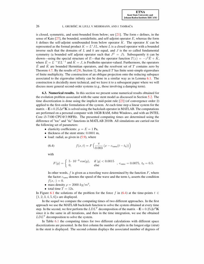
6.3. Numerical results. In this section we present some numerical results obtained forthe evolution problem associated with the same stent model as discussed in Section 5.2. Thetime discretization is done using the implicit mid-point rule [23] (of convergence order 2)applied to the first-order formulation of the system. At each time step a linear system for thematrix−E+0.25∆t2K is solved using the backslash operator in MATLAB. The computationsare performed on a personal computer with 16GB RAM, 64bit Windows, and with an INTELCore i3-7100 [email protected]. The presented computing times are determined using thedifference of "toc" and "tic" functions in MATLAB 2010b. All simulations are carried out forthe following set of parameters:
• elasticity coefficients: µ = E = 1 Pa,• thickness of the stent struts: 0.0001 m,• load: radial, as given in (5.9), where
(6.4) f(x, t) = F( π
0.003(x− cvawe(t− t0))
)with
F (y) =
5 · 10−8 cos(y), if |y| < 0.00150, else , cvawe = 0.0075, t0 = 0.5.
In other words, f is given as a traveling wave determined by the function F , wherethe factor cvawe denotes the speed of the wave and the term t0 asserts the conditionf(x, ·) = 0.
• mass density ρ = 2000 kg/m3,• total time T = 12s.
In Figure 6.1 the solutions of the problem for the force f in (6.4) at the time-points t ∈1, 2, 3, 4, 5, 6s are displayed.
In the sequel we compare the computing times of two different approaches. In the firstapproach we use the MATLAB backslash function to solve the system obtained at every timestep. In the second, we first perform the LDLT decomposition of the matrix−E + 0.25∆t2Ksince it is the same in all iterations, and then in the time integration, we use the obtainedLDLT decomposition to solve the system.
In Table 6.1 the computing times for two different calculations with different spacediscretizations are presented. In the first column the number of splits in the longest edge (strut)in the stent is displayed. The second column displays the associated number of degrees of

ETNAKent State University and
Johann Radon Institute (RICAM)
NUMERICAL SIMULATION OF ELASTIC FRAME STRUCTURES 27
0 5 10 15 20
x 10−3
−1.5
−1
−0.5
0
0.5
1
1.5
x 10−3
0 5 10 15 20
x 10−3
−1.5
−1
−0.5
0
0.5
1
1.5
x 10−3
0 5 10 15 20
x 10−3
−1.5
−1
−0.5
0
0.5
1
1.5
x 10−3
0 5 10 15 20
x 10−3
−1.5
−1
−0.5
0
0.5
1
1.5
x 10−3
0 5 10 15 20
x 10−3
−1.5
−1
−0.5
0
0.5
1
1.5
x 10−3
0 5 10 15 20
x 10−3
−1.5
−1
−0.5
0
0.5
1
1.5
x 10−3
FIG. 6.1. Solution of the problem projected to the (x1, x2)-plane for the loads given in (6.4) and at timest = 1s, 2s, 3s, 4s, 5s, and 6s.
TABLE 6.1Computing times for several space discretizations without and with LDLT precomputation.
no LDL using LDLT
# splits size of matrix time (s) time for precomputation (s) time for iterations (s)20 12462 476 1.34 11021 25710 554 1.70 20322 52206 793 4.62 39223 105198 1338 23.71 855
freedom. The remaining columns present the computing times. The results indicate that theuse of the factorization LDLT obviously pays off. Here the time step is equal to 2−4.
In Table 6.2 we compare the computing times for different time step sizes with the samefinal time T . The total time approximately doubles when lowering ∆t, which is natural since

ETNAKent State University and
Johann Radon Institute (RICAM)
28 L. GRUBIŠIC, M. LJULJ, V. MEHRMANN, AND J. TAMBACA
the number of time steps doubles. However, it is interesting to note that the time for thesolution with LDLT reduces when reducing ∆t. Here, every strut is split into 4 smaller struts.
TABLE 6.2Computing times for several values of ∆t without and with LDLT precomputation.
no LDL using LDLT
∆t time (s) time for precomputation (s) time for iterations (s)2−3 277 3.66 2022−4 554 1.77 3922−5 1120 1.52 8082−6 2332 1.39 1717
TABLE 6.3Relative L2(0, T ;L2(N ))-errors for different space meshes.
h−1 error20 0.04111079676079421 0.01534850177895222 0.00352472245804823 0.000224774470258
TABLE 6.4Relative L2(0, T ;L2(N ))-errors for different time steps.
∆t error2−3 0.0383702787649792−4 0.0230141490227352−5 0.0120512251643782−6 0.003154110021893
We have also computed the errors in the solutions. For the same time step we computedthe errors for different numbers of strut splits. The errors are presented in Table 6.3. Theyare calculated by comparing the solution with the solution for 24 strut splits. All errors arepresented in the L2(0, T ;L2(N ))-norm.
In Table 6.4 the errors are given for different ∆t and for a fixed space mesh. The errorsare computed with respect to ∆t = 2−7 and the same L2(0, T ;L2(N ))-norm. Movies ofthe dynamic behavior of the stent can be found in the additional resources to this paperhttp://etna.math.kent.edu/vol.54.2021/pp1-30.dir/stent_video.avi.
7. Conclusion. We have presented an extended model description for the numericalsimulation of elastic frame structures, which explicitly includes all constraints. Based on thenew formulation, an inf-sup inequality for the finite element discretization is shown, and,furthermore, a simple proof of the inf-sup inequality for the space continuous problem ispresented. Despite an increased number of degrees of freedom, the new formulation leadsto faster simulation times. The presented techniques are also used to simplify the analysisand the numerical solution of the evolution problem describing the movement of the structureunder external forces. Numerical examples from elastic stent models illustrate the theoreticalresults and show the effectiveness of the new modeling approach.

ETNAKent State University and
Johann Radon Institute (RICAM)
NUMERICAL SIMULATION OF ELASTIC FRAME STRUCTURES 29
REFERENCES
[1] S. S. ANTMAN, Nonlinear Problems of Elasticity, Springer, New York, 2005.[2] R. B. BAPAT, Graphs and Matrices, Springer, London, 2014.[3] C. BEATTIE, V. MEHRMANN, H. XU, AND H. ZWART, Linear port-Hamiltonian descriptor systems, Math.
Control Signals Systems, 30 (2018), Art. 17, 27 pages.[4] D. BOFFI, F. BREZZI, AND M. FORTIN, Mixed Finite Element Methods and Applications, Springer, Heidel-
berg, 2013.[5] A. BOROVSKIKH, R. MUSTAFOKULOV, K. LAZAREV, AND YU. POKORNYI, A class of fourth-order
differential equations on a spatial net, Dokl. Math., 52 (1995), pp. 433–435.[6] F. BREZZI AND M. FORTIN, Mixed and Hybrid Finite Element Methods, Springer, New York, 1991.[7] P. CANADAS, V. M. LAURENTZ, C. ODDOU, D. ISABEY, AND S. WENDLING, A cellular tensegrity model
to analyse the structural viscoelasticity of the cytoskeleton, J. Theo. Biol., 218 (2002), pp. 155–173.[8] D. Q. CAO AND R. W. TUCKER, Nonlinear dynamics of elastic rods using the Cosserat theory: modelling
and simulation, Internat. J. Solids Structures, 45 (2008), pp. 460–477.[9] G. CHEN, M. DELFOUR, A. KRALL, AND G. PAYRE, Modeling, stabilization and control of serially
connected beams, SIAM J. Control Optim., 25 (1987), pp. 526–546.[10] E. COSSERAT AND F. COSSERAT, Théorie des Corps Déformable, Hermann, Paris, 1909.[11] S. CANIC AND J. TAMBACA, Cardiovascular stents as PDE nets: 1D vs. 3D, IMA J. Appl. Math., 77 (2012),
pp. 748–770.[12] P. G. CIARLET, The Finite Element Method for Elliptic Problems, SIAM, Philadelphia, 2002.[13] C. D’APICE, R. MANZO, AND B. PICCOLI, Packet flow on telecommunication networks, SIAM J. Math.
Anal., 38 (2006), pp. 717–740.[14] B. DEKONINCK, AND S. NICAISE, The eigenvalue problem for networks of beams, Linear Algebra Appl.,
314 (2000), pp. 165–189.[15] L.C. EVANS, Partial Differential Equations, American Mathematical Society, Providence, 1998.[16] L. FORMAGGIA, A. QUARTERONI, AND A. VENEZIANI, eds., Cardiovascular Mathematics. Modeling and
simulation of the circulatory system, Springer, Milan, 2009.[17] V. GIRAULT AND P.-A. RAVIART, Finite Element Methods for Navier-Stokes Equations. Theory and
Algorithms, Springer, Berlin, 1986.[18] M. GARAVELLO AND B. PICCOLI, Trafic Flow on Networks, AIMS, Springfield, 2006.[19] G. GRISO, Asymptotic behavior of structures made of curved rods, Anal. Appl. (Singap.), 6 (2008), pp. 11–22.[20] L. GRUBIŠIC, J. IVEKOVIC, J. TAMBACA, AND B. ŽUGEC, Mixed formulation of the one-dimensional
equilibrium model for elastic stents, Rad Hrvat. Akad. Znan. Umjet. Mat. Znan., 21 (2017), pp. 219–240.[21] L. GRUBIŠIC, V. KOSTRYKIN, K.A. MAKAROV, AND K. VESELIC, Representation theorems for indefinite
quadratic forms revisited, Mathematika, 59 (2013), pp. 169–189.[22] L. GRUBIŠIC AND J. TAMBACA, Direct solution method for the equilibrium problem for elastic stents,
Numer. Linear Algebra Appl., 26 (2019), Art. e2231, 23 pages.[23] E. HAIRER AND G. WANNER, Solving Ordinary Differential Equations II: Stiff and Differential-Algebraic
Problems, Springer, Heidelberg, 1996.[24] C.R. HIBBELER, Engineering Mechanics: Statics, Macmillan, New York, 1983.[25] M. JURAK AND J. TAMBACA, Derivation and justification of a curved rod model, Math. Models Methods
Appl. Sci., 9 (1999), pp. 991–1014.[26] , Linear curved rod model. General curve, Math. Models Methods Appl. Sci., 11 (2001), pp. 1237–
1252.[27] T. KATO, Perturbation Theory for Linear Operators, Springer, New York, 2013.[28] F. KLEIN, B. RICHTER, T. STRIEBEL, C. M. FRANZ, G. VON FREYMANN, M. WEGENER, AND M. BAST-
MEYER, Two-component polymer scaffolds for controlled three-dimensional cell culture, AdvancedMaterials, 23 (2011), pp. 1341–1345.
[29] R. CH. KULAEV, On the solvability of a boundary value problem for a fourth-order equation on a graph,Differ. Equ., 50 (2014), pp. 25–32. Translation of Differ. Uravn., 50 (2014), pp. 27–34.
[30] P. KUNKEL AND V. MEHRMANN, Differential–Algebraic Equations. Analysis and Numerical Solution,European Mathematical Society, Zürich, 2006.
[31] P. KUNKEL, V. MEHRMANN, AND L. SCHOLZ, Self-adjoint differential-algebraic equations, Math. ControlSignals Systems, 26 (2014), pp. 47–76.
[32] J. E. LAGNESE, G. LEUGERING, AND E. J. P. G. SCHMIDT, Modeling, Analysis and Control of DynamicElastic Multi-link Structures, Birkhäuser, Boston, 1994.
[33] R. LAMOUR, R. MÄRZ, AND C. TISCHENDORF, Differential-Algebraic Equations: A Projector BasedAnalysis, Springer, Heidelberg, 2013.
[34] H. LE DRET, Problèmes Variationnels dans les Multi-Domaines, Masson, Paris, 1991.[35] D. S. MACKEY, N. MACKEY, C. MEHL, AND V. MEHRMANN, Structured polynomial eigenvalue problems:
good vibrations from good linearizations, SIAM J. Matrix Anal. Appl., 28 (2006), pp. 1029–1051.

ETNAKent State University and
Johann Radon Institute (RICAM)
30 L. GRUBIŠIC, M. LJULJ, V. MEHRMANN, AND J. TAMBACA
[36] R. MENNICKEN AND M. MÖLLER, Non-Self-Adjoint Boundary Eigenvalue Problems, North-Holland,Amsterdam, 2003.
[37] G. PARKE AND N. HEWSON, eds., ICE manual of bridge engineering, Thomas Telford, London, 2008.[38] G. PANASENKO, Multi-Scale Modelling for Structures and Composites, Springer, Dordrecht, 2005.[39] L. SCARDIA, The nonlinear bending-torsion theory for curved rods as Γ-limit of three-dimensional elasticity,
Asymtot. Anal., 47 (2006), pp. 317–343.[40] J. TAMBACA, Justification of the dynamic model of curved rods, Asymptot. Anal., 31 (2002), pp. 43–68.[41] J. TAMBACA, M. KOSOR, S. CANIC, AND D. PANIAGUA, Mathematical modeling of vascular stents, SIAM
J. Appl. Math., 70 (2010), pp. 1922–1952.[42] B. I. WOHLMUTH, A mortar finite element method using dual spaces for the Lagrange multiplier, SIAM J.
Numerical Analysis, 38 (2000), pp. 989–1012.[43] E. W. WONG, P. E. SHEEHAN, AND C. M. LIEBER, Nanobeam mechanics: elasticity, strength, and
toughness of nanorods and nanotubes, Science, 277 (1997), pp. 1971–1975.