Embed Size (px)
Citation preview

E. Nart, A. O. Ayhan*
Department of Mechanical Engineering
Sakarya University
54187 Sakarya, TURKEY
*E-mail: [email protected]
Modeling and Analysis of Three-Dimensional
Cracks Using Unstructured Finite Elements
1

Agenda
� Fracture Mechanics – Motivation and Needs
� 3D Fracture Mechanics – Available Methods/Tools
� Enriched Finite Elements for 3D Fracture Mechanics
� FCPAS – Fracture and Crack Propagation Analysis System
� Fracture finite element models developed using ANSYS
� Fracture finite element models developed by crack insertion into an uncracked model
� Fracture analysis by three-dimensional enriched finite elements
� Applications:
� Mode-I surface crack insertion into an uncracked finite-thickness plate
� Inclined and deflected surface crack insertion into an uncracked finite-thickness plate
� Fracture solutions by enriched finite elements
� Fatigue crack growth analysis of Mode-I surface crack in a plate under cyclic bending load
� Summary/Conclusions
2

• 152m long T2 tanker, 'Schenectady'
• 16 January 1943 (A few days after the
sea trials)
• Breaks into two parts while lying at the
harbor (Portland, Oregon)
• Still harbor water and about 4°C
• Light winds and air temperature about -
3°C
• Sudden failure heard a mile away
• Fracture extended through the deck, the
sides of the hull, the longitudinal
bulkheads and the bottom girders.
• Central part of the ship rose clear of the
water
Why Fracture Mechanics?
Poor welding in highly stressed region
Ref: http://www.twi.co.uk/j32k/protected/band_13/oilgas_caseup31.html 3
Schenectady T2 Tanker, January 16, 1943

• April 28, 1988, 1:25 pm Hilo to Honolulu
• Rupture of fuselage at the top of its climb
• Senior flight attendant blown from the aircraft to her death
• The cockpit door and roof blown away
• Most passengers were injured, seven seriously
Aloha Airlines Flight 243, April 28, 1988
Undetected “fatigue damage”
Ref: http://www.volpe.dot.gov/infosrc/journal/30th/safety.html 4
Why Fracture Mechanics?

Mechanical Life of A Part
+
5
Crack
Initiation
Crack
Propagation = Total Life
LCF, HCF, Creep,
Oxidation…
Fatigue & Creep
CP, Fracture
S-N, Goodman,
Creep Curves
Fracture Mech.,
da/DN, da/dt
Curves, KIC

Aluminum Plate
(Takashi et al, 2000)A Machine Part
(Dowling, 2002)
Turbine Bucket Dovetail
(Dumas et al, 2006)Electronic Package (D.
Peterson, 1998)
Fatigue Crack Propagation
Though many problems can be approximated by 2D methods, most real problems are 3D 6
3D Fracture Mechanics – Motivation and Needs
Agenda
7
� Fracture Mechanics – Motivation and Needs
� 3D Fracture Mechanics – Available Methods/Tools
� Enriched Finite Elements for 3D Fracture Mechanics
� FCPAS – Fracture and Crack Propagation Analysis System
� Fracture finite element models developed using ANSYS
� Fracture finite element models developed by crack insertion into an uncracked model
� Fracture analysis by three-dimensional enriched finite elements
� Applications:
� Mode-I surface crack insertion into an uncracked finite-thickness plate
� Inclined and deflected surface crack insertion into an uncracked finite-thickness plate
� Fracture solutions by enriched finite elements
� Fatigue crack growth analysis of Mode-I surface crack in a plate under cyclic bending load
� Summary/Conclusions

The Most Common Types of Cracks are Surface & Corner Cracks
8
X
Z
Y
θ a
2c
σ 0
σ 0
H
H
t
2W
α y’
z’
x’
X
Z
Y
θ a β
2c
σ 0
σ 0
H
H
t
2W
y’
z’
x’
Deflected Surface Crack Inclined Surface Crack
3D Fracture Mechanics

3D Fracture Mechanics – Available Methods/Tools
• Alternating methods
• Boundary element methods
• Virtual Crack Extension Method
• Line-Spring Method
• Finite Element Methods
� Quarter-point elements
� J & Interaction Integral
� Domain Integral
� Enriched Finite Elements
(Topic of This Presentation)
• Limited geometry
or loading
• Model and mesh
generation can be
time consuming
• Quicker to solve,
simple models and
geometries
• Accurate
representation of
actual geometry and
local loads near crack
region
• Multi-loading and
material model
capabilities
Disadvantages Advantages
9

Agenda
10
� Fracture Mechanics – Motivation and Needs
� 3D Fracture Mechanics – Available Methods/Tools
� Enriched Finite Elements for 3D Fracture Mechanics
� FCPAS – Fracture and Crack Propagation Analysis System
� Fracture finite element models developed using ANSYS
� Fracture finite element models developed by crack insertion into an uncracked model
� Fracture analysis by three-dimensional enriched finite elements
� Applications:
� Mode-I surface crack insertion into an uncracked finite-thickness plate
� Inclined and deflected surface crack insertion into an uncracked finite-thickness plate
� Fracture solutions by enriched finite elements
� Fatigue crack growth analysis of Mode-I surface crack in a plate under cyclic bending load
� Summary/Conclusions

Enriched Finite Elements for 3D Fracture Analysis
−+
−+=
∑∑
∑∑∑
==
===
nodel
j
jj
ntip
i
i
IIi
nodel
j
jj
ntip
i
i
Ii
nodel
j
jj
gNgKNZ
fNfKNZuNu
1
11
1
0
1
11
11
0
),,(),,()(),,(
),,(),,()(),,(),,(),,(
ρηξρηξξρηξ
ρηξρηξξρηξρηξρηξ
−+
−+=
∑∑
∑∑∑
==
===
nodel
j
jj
ntip
i
i
IIi
nodel
j
jj
ntip
i
i
Ii
nodel
j
jj
gNgKNZ
fNfKNZvNv
1
22
1
0
1
22
1
0
1
),,(),,()(),,(
),,(),,()(),,(),,(),,(
ρηξρηξξρηξ
ρηξρηξξρηξρηξρηξ
−+= ∑∑∑
===
nodel
j
jj
ntip
i
i
IIIi
nodel
j
jj hNhKNZwNw11
0
1
),,(),,()(),,(),,(),,( ρηξρηξξρηξρηξρηξ
Unknown Stress Intensity Factors Are Included in the FE Formulation & Solved for Directly 11

Agenda
12
� Fracture Mechanics – Motivation and Needs
� 3D Fracture Mechanics – Available Methods/Tools
� Enriched Finite Elements for 3D Fracture Mechanics
� FCPAS – Fracture and Crack Propagation Analysis System
� Fracture finite element models developed using ANSYS
� Fracture finite element models developed by crack insertion into an uncracked model
� Fracture analysis by three-dimensional enriched finite elements
� Applications:
� Mode-I surface crack insertion into an uncracked finite-thickness plate
� Inclined and deflected surface crack insertion into an uncracked finite-thickness plate
� Fracture solutions by enriched finite elements
� Fatigue crack growth analysis of Mode-I surface crack in a plate under cyclic bending load
� Summary/Conclusions

Fracture and Crack Propagation Analysis System (FCPAS)
Uncracked
Model
Insert Crack
and Re-mesh
Model
Apply B.C.’s
Analyze
Cracked Model
(FRAC3D)
Post-Process,
Check Failure
Predict Next
Crack Profile
Insert/Grow
New Crack
Re-mesh New
Cracked Model
Failed?
STOP
CALCULATE LIFE
Y
N
FCP
AS
GU
I
FCPAS GUI
FCP
AS
GU
I
FCPAS GUI 13

FRAC3D – FCPAS Solver for 3D Fracture Analysis
• Supported Element Types
ξξξξ
ηηηη
ρρρρ
ξξξξ
ηηηη
ρρρρ
ξξξξ
ηηηη
ρρρρ
ξξξξ
ηηηη
ρρρρ
32-Node Hexahedron
20-Node Hexahedron
26-Node Pentahedron
10-Node Tetrahedron
ξξξξ
ηηηη
ρρρρ
15-Node Pentahedron
14

Boundary Conditions
• Load Types
– Pressure Loading on Surfaces
– Concentrated Forces on Nodes
– Thermal Loading
– Inertia Loading
– Centrifugal Loading
• Constraints
– Displacement Constraints on
Nodes
– Constraints on Node Sets (Tied
Nodes)
– Displacements on Skew Edges
– Sub-model BC’s from ANSYS
15
FRAC3D – FCPAS Solver for 3D Fracture Analysis
Analysis Types & Material Systems Supported
• Analysis Types
– Elastic Stress Analysis
– Elastic/Plastic Stress Analysis
– Linear Elastic Fracture Mechanics w/ & w/o plasticity on uncracked material
– Submodeling of ANSYS models
• Material Systems
– Homogeneous Isotropic
– Bi-material Isotropic
– Homogeneous Orthotropic
– FGM Isotropic
– Elastic/plastic Isotropic
16
FRAC3D – FCPAS Solver for 3D Fracture Analysis

Agenda
17
� Fracture Mechanics – Motivation and Needs
� 3D Fracture Mechanics – Available Methods/Tools
� Enriched Finite Elements for 3D Fracture Mechanics
� FCPAS – Fracture and Crack Propagation Analysis System
� Fracture finite element models developed using ANSYS
� Fracture finite element models developed by crack insertion into an uncracked model
� Fracture analysis by three-dimensional enriched finite elements
� Applications:
� Mode-I surface crack insertion into an uncracked finite-thickness plate
� Inclined and deflected surface crack insertion into an uncracked finite-thickness plate
� Fracture solutions by enriched finite elements
� Fatigue crack growth analysis of Mode-I surface crack in a plate under cyclic bending load
� Summary/Conclusions

18
Applications: Crack Insertion (Mode-I Surface Crack)
2W
2H
t
Uncracked Plate Finite
Element Model
An Elliptical Crack Shape to
be Inserted into Plate Model
Info for …
Location, Size and Orientation of the crack are needed !

19
Applications: Crack Insertion (Mode-I Surface Crack)
Select A Chunk Region
Separate Chunk Exterior
Mesh Facets
Chunk Outer Free
Surface
Chunk outer
shared-surface
20
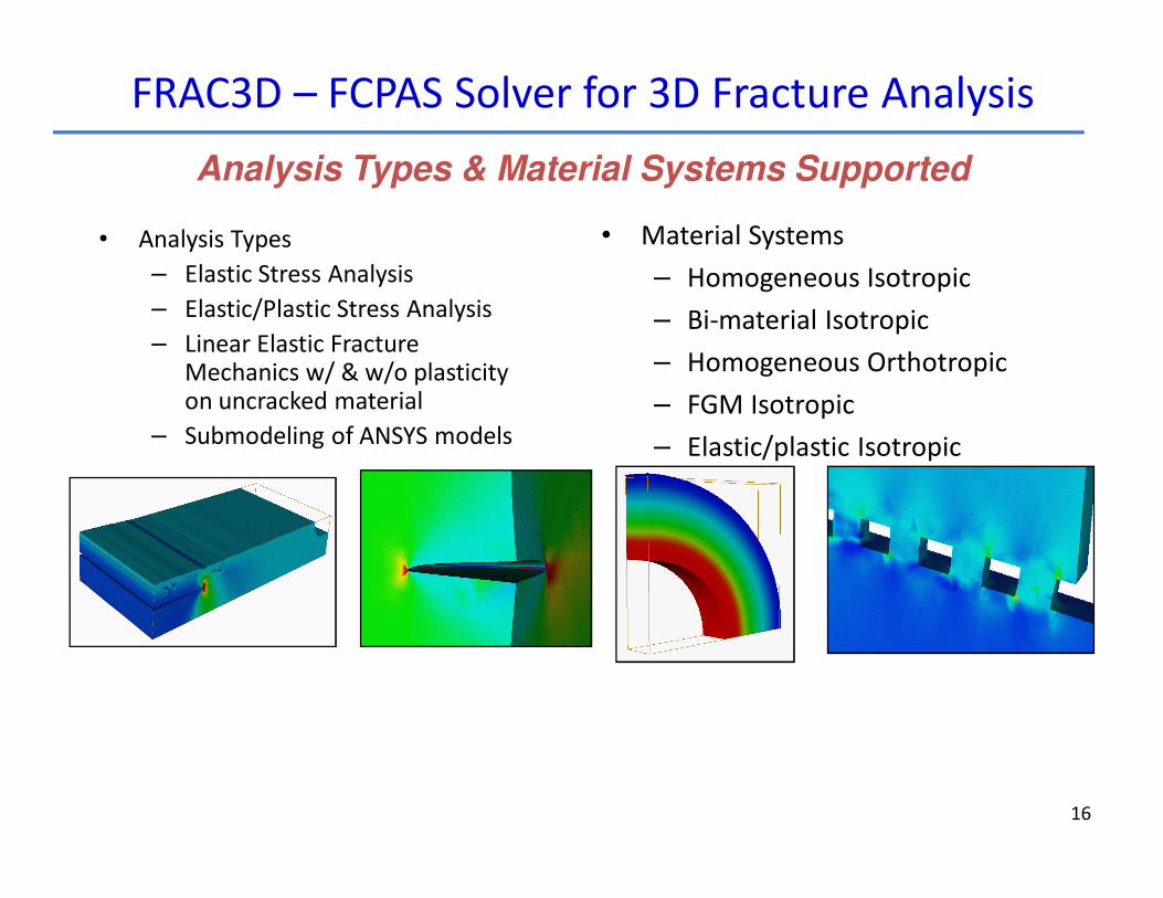
Applications: Crack Insertion (Mode-I Surface Crack)
Combination of the crack mouth line and crack front line
2D meshing by Triangle©,1
©,1 Shewchuk, J.R., 1996. Triangle: engineering a 2D quality mesh generator and Delaunay triangulator. In: Ming C., Dinesh
M, editors. Applied computational geometry: towards geometric engineering. Springer-Verlag. 1148, pp. 203-222.
Combine the modified chunk exterior facets

21©,2 Tetgen software website, http://tetgen.berlios.de/
Applications: Crack Insertion (Mode-I Surface Crack)
3D meshing of Chunk Domain by Tetgen©,2
Constrained volume meshing for keeping,
• chunk outer surface facets,
• crack surfaces meshing by Triangle ©, and
• crack mouth-line nodal points
unchanged.

22
Applications: Crack Insertion (Mode-I Surface Crack)
Consolidation of chunk volume mesh by Tetgen© with plate without the chunk
Consolidation of chunk mesh with plate,
• node numbers on the shared surfaces kept the same,
• displacement and load boundary conditions outside
chunk zone book kept,
• nodes on the crack surfaces duplicated and surface split,
• nodes and elements along crack front book kept to
define the local crack front geometry.
The fully-unstructured finite element mesh w/ crack included (a/t=0.2, a/c=0.2)
(Next step Fracture Analysis by 3D Enriched Elements)

23
Applications: Crack Insertion (Mode-I Surface Crack)
a/c=0.2
a/t=0.2 a/t=0.5
a/t=0.8

24
Applications: Crack Insertion (Mode-I Surface Crack)
a/c=1.0
a/t=0.2 a/t=0.5
a/t=0.8

25
Applications: Crack Insertion (Mode-I Surface Crack)
a/c=2.0
a/t=0.2 a/t=0.5
a/t=0.8

26
Applications: Crack Insertion (Mode-I Surface Crack)
a/c=0.2
Deformed shapes as a first-step validation of the mesh
27
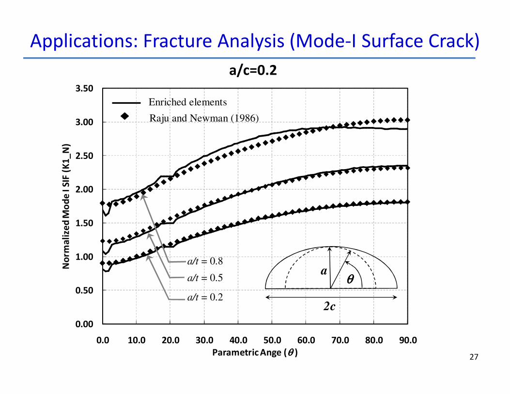
Applications: Fracture Analysis (Mode-I Surface Crack)
0.00
0.50
1.00
1.50
2.00
2.50
3.00
3.50
0.0 10.0 20.0 30.0 40.0 50.0 60.0 70.0 80.0 90.0
No
rma
lize
d M
od
e I
SIF
(K
1_
N)
Parametric Ange (θ θ θ θ )
Enriched elements
Raju and Newman (1986)
a/t = 0.8
a/t = 0.5
a/t = 0.2
2c
aθθθθ
a/c=0.2
28
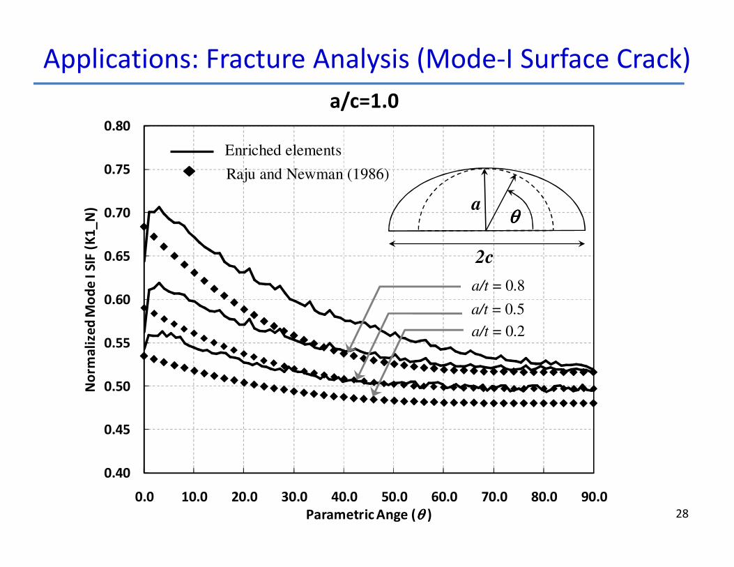
a/c=1.0
0.40
0.45
0.50
0.55
0.60
0.65
0.70
0.75
0.80
0.0 10.0 20.0 30.0 40.0 50.0 60.0 70.0 80.0 90.0
No
rma
lize
d M
od
e I
SIF
(K
1_
N)
Parametric Ange (θ θ θ θ )
Enriched elements
Raju and Newman (1986)
a/t = 0.8
a/t = 0.5
a/t = 0.2
2c
aθθθθ
Applications: Fracture Analysis (Mode-I Surface Crack)

29
a/c=2.0
0.40
0.50
0.60
0.70
0.80
0.90
1.00
0.0 10.0 20.0 30.0 40.0 50.0 60.0 70.0 80.0 90.0
No
rma
lize
d M
od
e I
SIF
(K
1_
N)
Parametric Ange (θ θ θ θ )
Enriched elements
Raju and Newman (1986)
a/t = 0.8
a/t = 0.5
a/t = 0.2
2c
aθθθθ
Applications: Fracture Analysis (Mode-I Surface Crack)
30
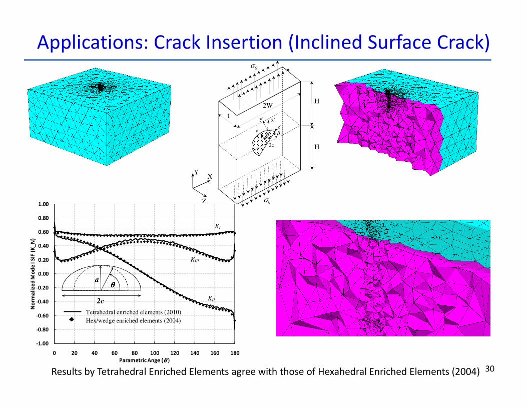
X
Z
Y
θ a β
2c
σ 0
σ 0
H
H
t
2W
y’
z’
x’
-1.00
-0.80
-0.60
-0.40
-0.20
0.00
0.20
0.40
0.60
0.80
1.00
0 20 40 60 80 100 120 140 160 180
No
rma
lize
d M
od
e I
SIF
(K
_N
)
Parametric Ange (θθθθ )
KII
Hex/wedge enriched elements (2004)
KIII
KI
Tetrahedral enriched elements (2010)
2c
aθθθθ
Applications: Crack Insertion (Inclined Surface Crack)
Results by Tetrahedral Enriched Elements agree with those of Hexahedral Enriched Elements (2004)
31
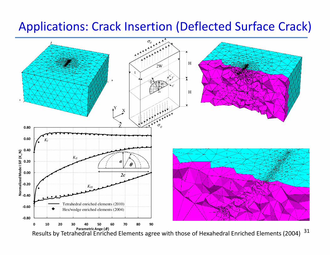
Applications: Crack Insertion (Deflected Surface Crack)
X
Z
Y
θ a
2c
σ 0
σ 0
H
H
t
2W
α y’
z’
x’
-0.80
-0.60
-0.40
-0.20
0.00
0.20
0.40
0.60
0.80
0 10 20 30 40 50 60 70 80 90
No
rma
lize
d M
od
e I
SIF
(K
_N
)
Parametric Ange (θθθθ )
KII
Hex/wedge enriched elements (2004)
KIII
KI
Tetrahedral enriched elements (2010)
2c
aθθθθ
Results by Tetrahedral Enriched Elements agree with those of Hexahedral Enriched Elements (2004)

32
FCPAS Fatigue Crack Propagation Analysis (FE Models by ANSYSTM)C
rack L
ength
(mm
)
Number of Cycles
Experiment(Reytier, M., 2004)* Crack Profiles by FCPAS
FCPAS
FCPAS Simulation Results Agree Very Well with Experimental Observations*(The permission by OMMI (Power Plant: Operation Maintenance and Materials Issues) and its publisher European Technology
Development Ltd. UK, for reproducing and republishing data by Reytier, M. is gratefully acknowledged.)
Surface Crack in a Finite-Thickness
Plate under Bending Load
Agenda
33
� Fracture Mechanics – Motivation and Needs
� 3D Fracture Mechanics – Available Methods/Tools
� Enriched Finite Elements for 3D Fracture Mechanics
� FCPAS – Fracture and Crack Propagation Analysis System
� Fracture finite element models developed using ANSYS
� Fracture finite element models developed by crack insertion into an uncracked model
� Fracture analysis by three-dimensional enriched finite elements
� Applications:
� Mode-I surface crack insertion into an uncracked finite-thickness plate
� Inclined and deflected surface crack insertion into an uncracked finite-thickness plate
� Fracture solutions by enriched finite elements
� Fatigue crack growth analysis of Mode-I surface crack in a plate under cyclic bending load
� Summary/Conclusions
34
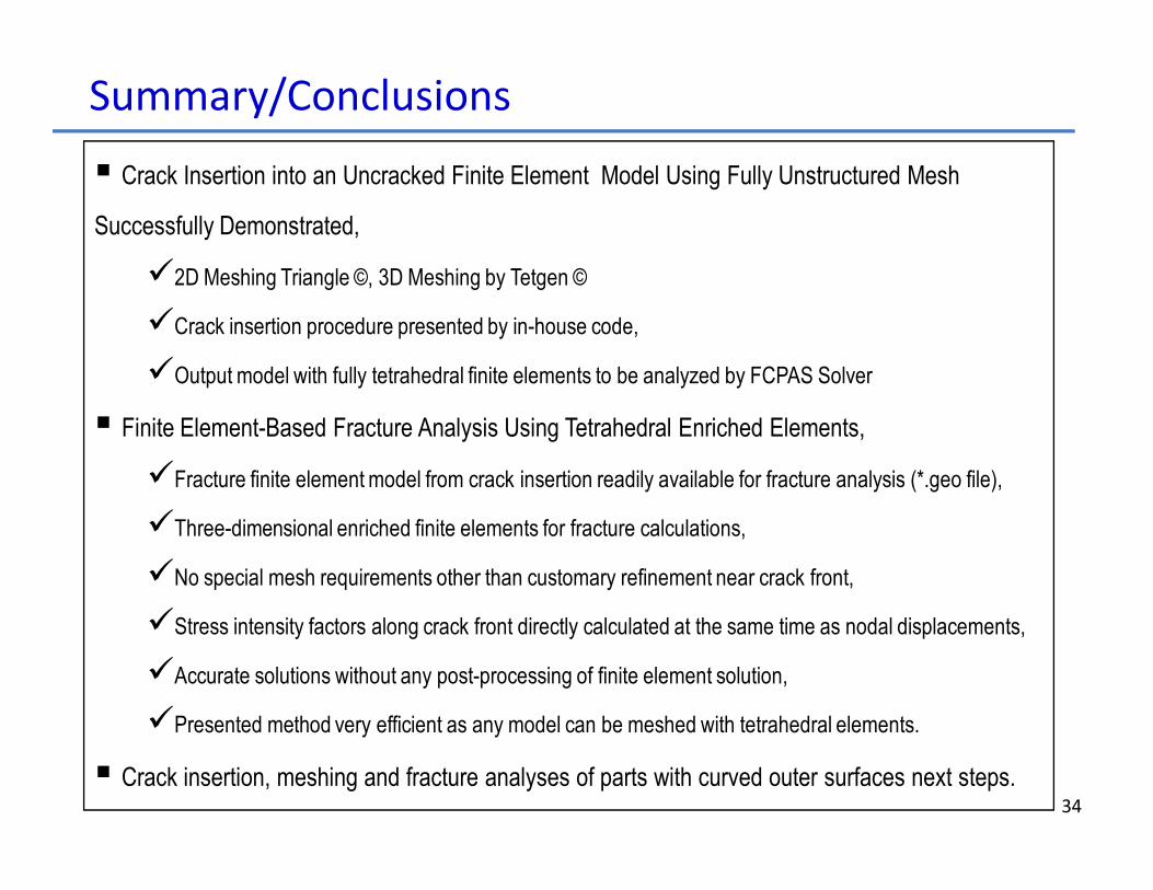
� Crack Insertion into an Uncracked Finite Element Model Using Fully Unstructured Mesh
Successfully Demonstrated,
�2D Meshing Triangle ©, 3D Meshing by Tetgen ©
�Crack insertion procedure presented by in-house code,
�Output model with fully tetrahedral finite elements to be analyzed by FCPAS Solver
� Finite Element-Based Fracture Analysis Using Tetrahedral Enriched Elements,
�Fracture finite element model from crack insertion readily available for fracture analysis (*.geo file),
�Three-dimensional enriched finite elements for fracture calculations,
�No special mesh requirements other than customary refinement near crack front,
�Stress intensity factors along crack front directly calculated at the same time as nodal displacements,
�Accurate solutions without any post-processing of finite element solution,
�Presented method very efficient as any model can be meshed with tetrahedral elements.
� Crack insertion, meshing and fracture analyses of parts with curved outer surfaces next steps.
Summary/Conclusions

35
Acknowledgements
�Authors are thankful to The Scientific and
Technological Research Council of Turkey (TUBITAK)
for the financial support and to the administration
and personnel of Çukurova and Sakarya Universities
for the organizational support.
�Authors are thankful to The Scientific and
Technological Research Council of Turkey (TUBITAK)
for the financial support and to the administration
and personnel of Çukurova and Sakarya Universities
for the organizational support.