Embed Size (px)
Citation preview
MODEL YK (STYLE G) R-134a
WITH OPTIVIEWTM CONTROL CENTER FOR ELECTRO-MECHANICAL STARTER,
SOLID STATE STARTER AND VARIABLE SPEED DRIVE
CENTRIFUGAL LIQUID CHILLERS
OPERATIONS AND MAINTENANCE Supersedes: 160.75-O1 (211) Form 160.75-O1 (617)
LD15222
Issue Date: June 9, 2017
JOHNSON CONTROLS2
FORM 160.75-O1 ISSUE DATE: 6/9/2017
This equipment is a relatively complicated apparatus. During rigging, installation, operation, maintenance, or service, individuals may be exposed to certain com-ponents or conditions including, but not limited to: heavy objects, refrigerants, materials under pressure, rotating components, and both high and low voltage. Each of these items has the potential, if misused or handled improperly, to cause bodily injury or death. It is the obligation and responsibility of rigging, instal-lation, and operating/service personnel to identify and recognize these inherent hazards, protect themselves, and proceed safely in completing their tasks. Failure to comply with any of these requirements could result in serious damage to the equipment and the property in
IMPORTANT!READ BEFORE PROCEEDING!
GENERAL SAFETY GUIDELINES
which it is situated, as well as severe personal injury or death to themselves and people at the site.
This document is intended for use by owner-authorized rigging, installation, and operating/service personnel. It is expected that these individuals possess independent training that will enable them to perform their assigned tasks properly and safely. It is essential that, prior to performing any task on this equipment, this individual shall have read and understood the on-product labels, this document and any referenced materials. This in-dividual shall also be familiar with and comply with all applicable industry and governmental standards and regulations pertaining to the task in question.
SAFETY SYMBOLSThe following symbols are used in this document to alert the reader to specific situations:
Indicates a possible hazardous situation which will result in death or serious injury if proper care is not taken.
Indicates a potentially hazardous situa-tion which will result in possible injuries or damage to equipment if proper care is not taken.
Identifies a hazard which could lead to damage to the machine, damage to other equipment and/or environmental pollu-tion if proper care is not taken or instruc-tions and are not followed.
Highlights additional information useful to the technician in completing the work being performed properly.
External wiring, unless specified as an optional connection in the manufacturer’s product line, is not to be connected inside the OptiView cabinet. Devices such as relays, switches, transducers and controls and any external wiring must not be installed inside the micro panel. All wiring must be in accordance with Johnson Controls’ published specifications and must be performed only by a qualified electrician. Johnson Controls will NOT be responsible for damage/problems resulting from improper connections to the controls or application of improper control signals. Failure to follow this warn-ing will void the manufacturer’s warranty and cause serious damage to property or personal injury.
JOHNSON CONTROLS 3
FORM 160.75-O1 ISSUE DATE: 6/9/2017
CHANGEABILITY OF THIS DOCUMENT
In complying withIn complying with Johnson Con-trols’ policy for continuous product improvement, the information contained in this document is subject to change without notice. Johnson Controls makes no commitment to update or provide current information automatically to the manual or product owner. Updated manuals, if applicable, can be obtained by contacting the nearest Johnson Controls Service office or access-ing the Johnson Controls QuickLIT website at http://cgproducts.johnsoncontrols.com.
It is the responsibility of rigging, lifting, and operating/ service personnel to verify the applicability of these documents to the equipment. If there is any question
regarding the applicability of these documents, rig-ging, lifting, and operating/service personnel should verify whether the equipment has been modified and if current literature is available from the owner of the equipment prior to performing any work on the chiller.
CHANGE BARSRevisions made to this document are indicated with a line along the left or right hand column in the area the revision was made. These revisions are to technical in-formation and any other changes in spelling, grammar or formatting are not included.
ASSOCIATED LITERATURE
MANUAL DESCRIPTION FORM NUMBER
Variable Speed Drive – Operation 160.00-O1
Solid State Starter – Operation and Maintenance 160.00-O2
Floor Mounted MV SSS – Operation 160.00-O5
Unit Mounted MV SSS – Operation 160.00-O7
Installation – Unit 160.75-N1
Optiview™ Control Center – Operation and Maintenance 160.54-O1
Wiring Diagram – Field Connections for YK Chiller (Style G) OptiView Control Center with Remote Low or Medium Voltage EMS or Unit Mounted Low or Medium Voltage SSS
160.75-PW1
Wiring Diagram – Field Connections for YK Chiller (Style G) OptiView Control Center with Remote Medium Voltage SSS
160.75-PW2
Wiring Diagram – Field Connections for YK Chiller (Style G) OptiView Control Center with Remote Medium Voltage VSD
160.75-PW3
Wiring Diagram – Field Control Modifications for YK Chiller (Style G) 160.75-PW4
Wiring Diagram – YK Chiller (Style G) OptiView Control Center with Remote Low or Medium Voltage EMS 160.75-PW5
Wiring Diagram – YK Chiller (Style G) OptiView Control Center with Unit Mounted Low or Medium Voltage SSS, Unit Mounted Low Voltage VSD with Modbus, or Remote Medium Voltage VSD
160.75-PW6
Wiring Diagram – YK Chiller (Style G) OptiView Control Center with LTC I/O Board with Remote Low or Medium Voltage EMS
160.75-PW7
Wiring Diagram – YK Chiller (Style G) OptiView Control Center w/ LTC I/O Board with Unit Mounted Low or Medium Voltage SSS, Unit Mounted Low Voltage VSD with Modbus or Remote Medium Voltage VSD
160.75-PW8
Renewal Parts – Unit 160.75-RP1
Renewal Parts – OptiView Control Center 160.54-RP1
JOHNSON CONTROLS4
FORM 160.75-O1 ISSUE DATE: 6/9/2017
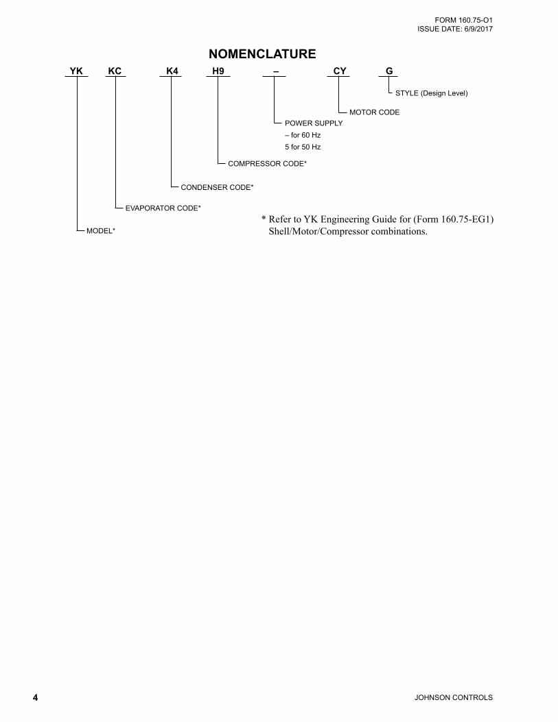
NOMENCLATURE YK KC K4 H9 – CY G
MOTOR CODEPOWER SUPPLY– for 60 Hz5 for 50 Hz
COMPRESSOR CODE*
CONDENSER CODE*
EVAPORATOR CODE*
MODEL*
STYLE (Design Level)
* Refer to YK Engineering Guide for (Form 160.75-EG1) Shell/Motor/Compressor combinations.
JOHNSON CONTROLS 5
FORM 160.75-O1 ISSUE DATE: 6/9/2017
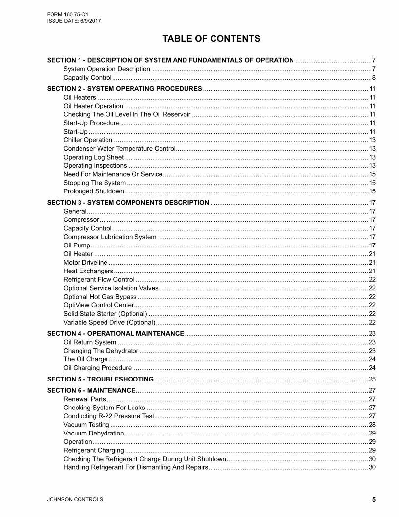
TABLE OF CONTENTS
SECTION 1 - DESCRIPTION OF SYSTEM AND FUNDAMENTALS OF OPERATION ..........................................7System Operation Description .........................................................................................................................7Capacity Control ...............................................................................................................................................8
SECTION 2 - SYSTEM OPERATING PROCEDURES ........................................................................................... 11Oil Heaters ..................................................................................................................................................... 11Oil Heater Operation ...................................................................................................................................... 11Checking The Oil Level In The Oil Reservoir ................................................................................................. 11Start-Up Procedure ........................................................................................................................................ 11Start-Up .......................................................................................................................................................... 11Chiller Operation ............................................................................................................................................13Condenser Water Temperature Control ..........................................................................................................13Operating Log Sheet ......................................................................................................................................13Operating Inspections ....................................................................................................................................13Need For Maintenance Or Service .................................................................................................................15Stopping The System .....................................................................................................................................15Prolonged Shutdown ......................................................................................................................................15
SECTION 3 - SYSTEM COMPONENTS DESCRIPTION .......................................................................................17General ...........................................................................................................................................................17Compressor ....................................................................................................................................................17Capacity Control .............................................................................................................................................17Compressor Lubrication System ...................................................................................................................17Oil Pump .........................................................................................................................................................17Oil Heater .......................................................................................................................................................21Motor Driveline ...............................................................................................................................................21Heat Exchangers ............................................................................................................................................21Refrigerant Flow Control ................................................................................................................................22Optional Service Isolation Valves ...................................................................................................................22Optional Hot Gas Bypass ...............................................................................................................................22OptiView Control Center .................................................................................................................................22Solid State Starter (Optional) .........................................................................................................................22Variable Speed Drive (Optional) .....................................................................................................................22
SECTION 4 - OPERATIONAL MAINTENANCE .....................................................................................................23Oil Return System ..........................................................................................................................................23Changing The Dehydrator ..............................................................................................................................23The Oil Charge ...............................................................................................................................................24Oil Charging Procedure ..................................................................................................................................24
SECTION 5 - TROUBLESHOOTING ......................................................................................................................25
SECTION 6 - MAINTENANCE ................................................................................................................................27Renewal Parts ................................................................................................................................................27Checking System For Leaks ..........................................................................................................................27Conducting R-22 Pressure Test......................................................................................................................27Vacuum Testing ..............................................................................................................................................28Vacuum Dehydration ......................................................................................................................................29Operation ........................................................................................................................................................29Refrigerant Charging ......................................................................................................................................29Checking The Refrigerant Charge During Unit Shutdown ..............................................................................30Handling Refrigerant For Dismantling And Repairs ........................................................................................30
JOHNSON CONTROLS6
FORM 160.75-O1 ISSUE DATE: 6/9/2017
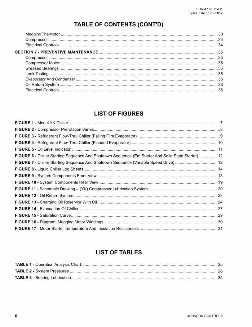
LIST OF FIGURES
LIST OF TABLES
FIGURE 1 - Model YK Chiller ....................................................................................................................................7FIGURE 2 - Compressor Prerotation Vanes ..............................................................................................................8FIGURE 3 - Refrigerant Flow-Thru Chiller (Falling Film Evaporator) ........................................................................9FIGURE 4 - Refrigerant Flow-Thru Chiller (Flooded Evaporator)............................................................................10FIGURE 5 - Oil Level Indicator ............................................................................................................................... 11FIGURE 6 - Chiller Starting Sequence And Shutdown Sequence (Em Starter And Solid State Starter) ................12FIGURE 7 - Chiller Starting Sequence And Shutdown Sequence (Variable Speed Drive) .....................................12FIGURE 8 - Liquid Chiller Log Sheets .....................................................................................................................14FIGURE 9 - System Components Front View .........................................................................................................18FIGURE 10 - System Components Rear View ........................................................................................................19FIGURE 11 - Schematic Drawing – (YK) Compressor Lubrication System.............................................................20FIGURE 12 - Oil Return System..............................................................................................................................23FIGURE 13 - Charging Oil Reservoir With Oil .........................................................................................................24FIGURE 14 - Evacuation Of Chiller .........................................................................................................................27FIGURE 15 - Saturation Curve ................................................................................................................................29FIGURE 16 - Diagram, Megging Motor Windings ...................................................................................................30FIGURE 17 - Motor Starter Temperature And Insulation Resistances ....................................................................31
Megging The Motor .........................................................................................................................................30Compressor ....................................................................................................................................................33Electrical Controls ..........................................................................................................................................34
SECTION 7 - PREVENTIVE MAINTENANCE ........................................................................................................35Compressor ....................................................................................................................................................35Compressor Motor ..........................................................................................................................................35Greased Bearings .........................................................................................................................................35Leak Testing ...................................................................................................................................................36Evaporator And Condenser ............................................................................................................................36Oil Return System ..........................................................................................................................................36Electrical Controls ..........................................................................................................................................36
TABLE OF CONTENTS (CONT'D)
TABLE 1 - Operation Analysis Chart .......................................................................................................................25TABLE 2 - System Pressures .................................................................................................................................28TABLE 3 - Bearing Lubrication ................................................................................................................................35
JOHNSON CONTROLS 7
FORM 160.75-O1 ISSUE DATE: 6/9/2017
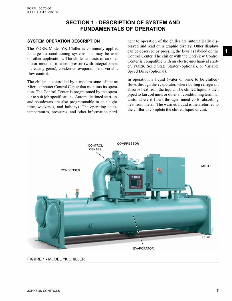
nent to operation of the chiller are automatically dis-played and read on a graphic display. Other displays can be observed by pressing the keys as labeled on the Control Center. The chiller with the OptiView Control Center is compatible with an electro-mechanical start-er, YORK Solid State Starter (optional), or Variable Speed Drive (optional).
In operation, a liquid (water or brine to be chilled) flows through the evaporator, where boiling refrigerant absorbs heat from the liquid. The chilled liquid is then piped to fan coil units or other air conditioning terminal units, where it flows through finned coils, absorbing heat from the air. The warmed liquid is then returned to the chiller to complete the chilled liquid circuit.
SECTION 1 - DESCRIPTION OF SYSTEM AND FUNDAMENTALS OF OPERATION
SYSTEM OPERATION DESCRIPTION The YORK Model YK Chiller is commonly applied to large air conditioning systems, but may be used on other applications. The chiller consists of an open motor mounted to a compressor (with integral speed increasing gears), condenser, evaporator and variable flow control.
The chiller is controlled by a modern state of the art Microcomputer Control Center that monitors its opera-tion. The Control Center is programmed by the opera-tor to suit job specifications. Automatic timed start-ups and shutdowns are also programmable to suit night-time, weekends, and holidays. The operating status, temperatures, pressures, and other information perti-
1
LD15222
CONDENSER
CONTROL CENTER
COMPRESSOR
MOTOR
EVAPORATOR
FIGURE 1 - MODEL YK CHILLER
JOHNSON CONTROLS8
FORM 160.75-O1 ISSUE DATE: 6/9/2017SECTION 1 - DESCRIPTION OF SYSTEM AND FUNDAMENTALS OF OPERATION
7619A(D)
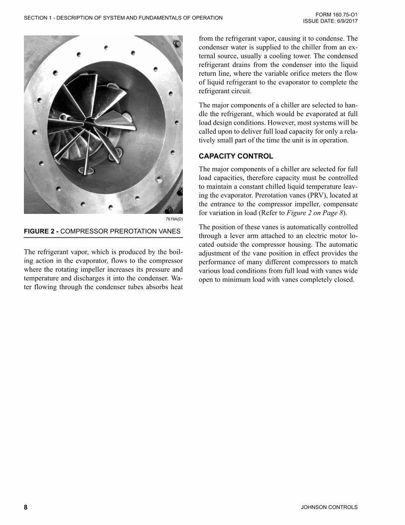
FIGURE 2 - COMPRESSOR PREROTATION VANES
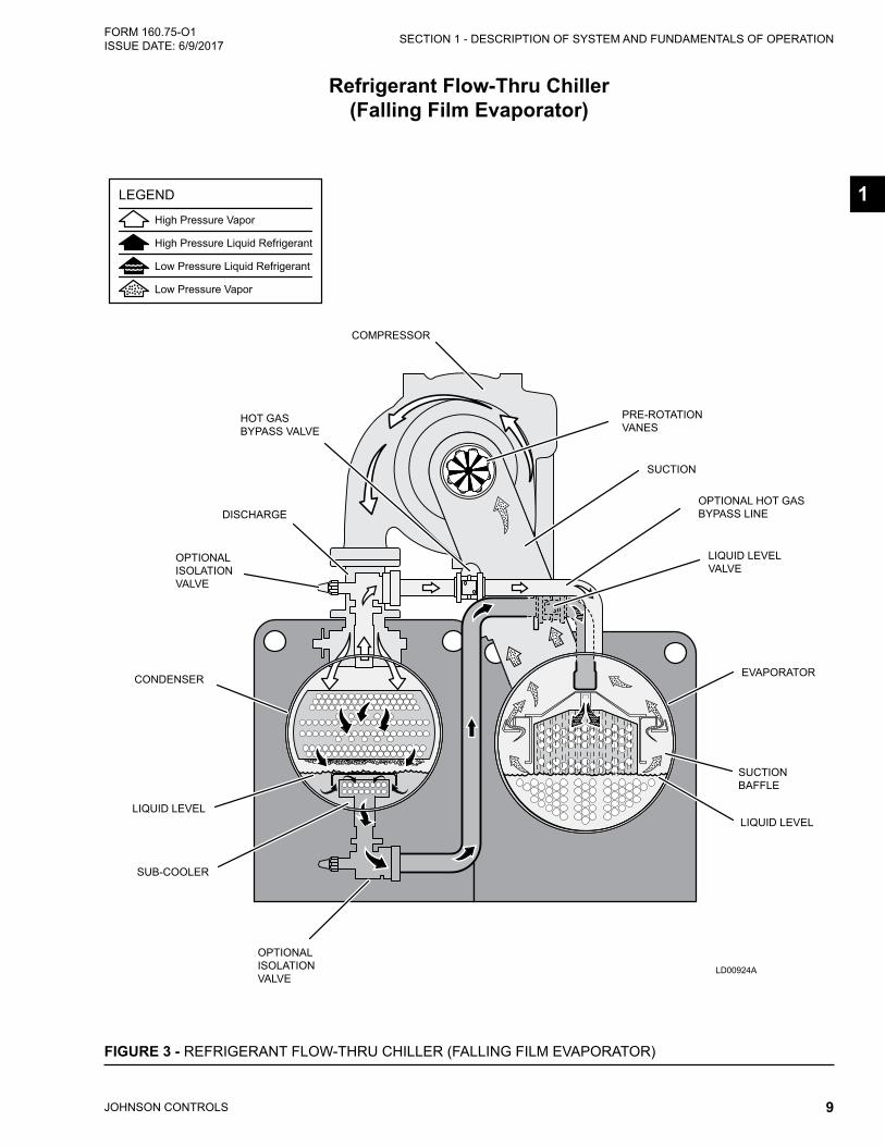
The refrigerant vapor, which is produced by the boil-ing action in the evaporator, flows to the compressor where the rotating impeller increases its pressure and temperature and discharges it into the condenser. Wa-ter flowing through the condenser tubes absorbs heat
from the refrigerant vapor, causing it to condense. The condenser water is supplied to the chiller from an ex-ternal source, usually a cooling tower. The condensed refrigerant drains from the condenser into the liquid return line, where the variable orifice meters the flow of liquid refrigerant to the evaporator to complete the refrigerant circuit.
The major components of a chiller are selected to han-dle the refrigerant, which would be evaporated at full load design conditions. However, most systems will be called upon to deliver full load capacity for only a rela-tively small part of the time the unit is in operation.
CAPACITY CONTROLThe major components of a chiller are selected for full load capacities, therefore capacity must be controlled to maintain a constant chilled liquid temperature leav-ing the evaporator. Prerotation vanes (PRV), located at the entrance to the compressor impeller, compensate for variation in load (Refer to Figure 2 on Page 8).
The position of these vanes is automatically controlled through a lever arm attached to an electric motor lo-cated outside the compressor housing. The automatic adjustment of the vane position in effect provides the performance of many different compressors to match various load conditions from full load with vanes wide open to minimum load with vanes completely closed.
JOHNSON CONTROLS 9
SECTION 1 - DESCRIPTION OF SYSTEM AND FUNDAMENTALS OF OPERATION FORM 160.75-O1 ISSUE DATE: 6/9/2017
1
Refrigerant Flow-Thru Chiller (Falling Film Evaporator)
FIGURE 3 - REFRIGERANT FLOW-THRU CHILLER (FALLING FILM EVAPORATOR)Rev. 2 (10-11-2010)Dan [email protected](717) 771-7535
YK Mod GRefrigerant Flow-Thru Cross-Section Diagram
(Falling-Film Evaporator)
LEGEND
High Pressure Vapor
High Pressure Liquid Refrigerant
Low Pressure Liquid Refrigerant
Low Pressure Vapor
COMPRESSOR
EVAPORATOR
DISCHARGE
PRE-ROTATIONVANES
SUCTIONBAFFLE
SUB-COOLER
LIQUID LEVEL
CONDENSER
LIQUID LEVELVALVE
HOT GASBYPASS VALVE
LIQUID LEVEL
SUCTION
OPTIONALISOLATIONVALVE
OPTIONALISOLATIONVALVE
OPTIONAL HOT GASBYPASS LINE
LD00924A
JOHNSON CONTROLS10
FORM 160.75-O1 ISSUE DATE: 6/9/2017SECTION 1 - DESCRIPTION OF SYSTEM AND FUNDAMENTALS OF OPERATION
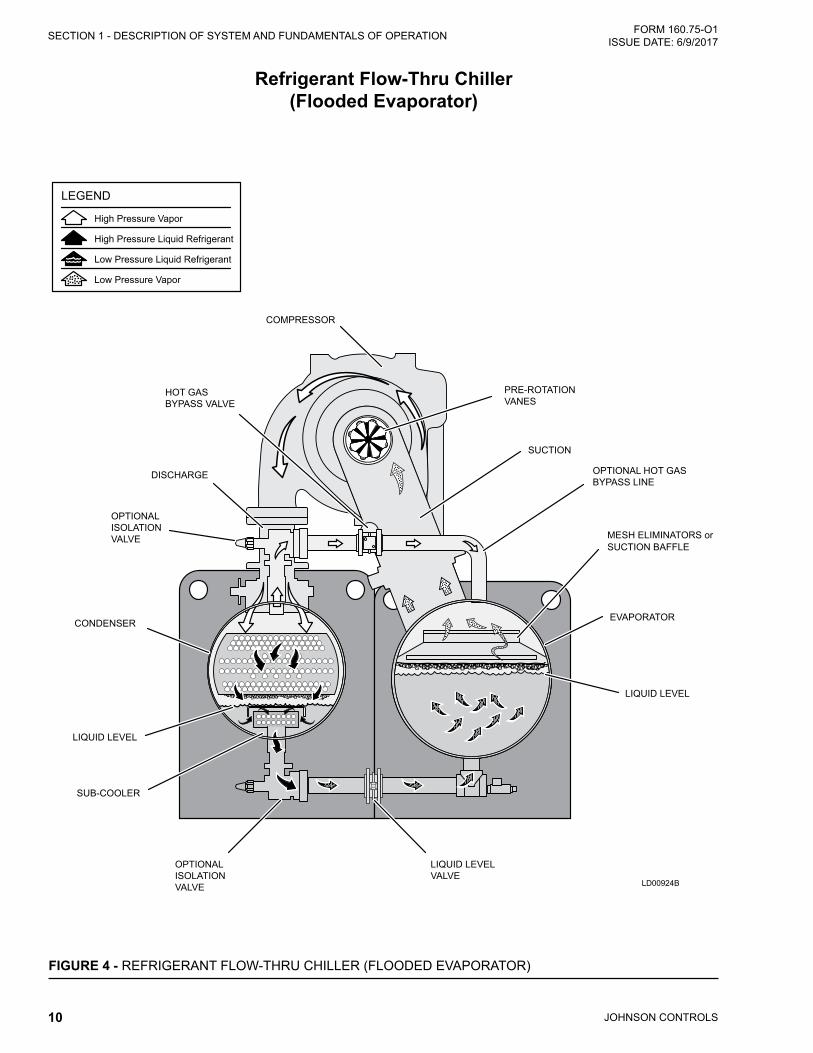
Refrigerant Flow-Thru Chiller (Flooded Evaporator)
FIGURE 4 - REFRIGERANT FLOW-THRU CHILLER (FLOODED EVAPORATOR)
Rev. 2 (12-09-2010)Dan [email protected](717) 771-7535
YK Mod GRefrigerant Flow-Thru Cross-Section Diagram
(Flooded Evaporator)
High Pressure Vapor
High Pressure Liquid Refrigerant
Low Pressure Liquid Refrigerant
Low Pressure Vapor
LEGEND
COMPRESSOR
EVAPORATOR
DISCHARGE
PRE-ROTATIONVANES
MESH ELIMINATORS orSUCTION BAFFLE
SUB-COOLER
LIQUID LEVEL
CONDENSER
SUCTION
LIQUID LEVELVALVE
LIQUID LEVEL
OPTIONALISOLATIONVALVE
OPTIONALISOLATIONVALVE
HOT GASBYPASS VALVE
OPTIONAL HOT GASBYPASS LINE
LD00924B
JOHNSON CONTROLS 11
FORM 160.75-O1 ISSUE DATE: 6/9/2017
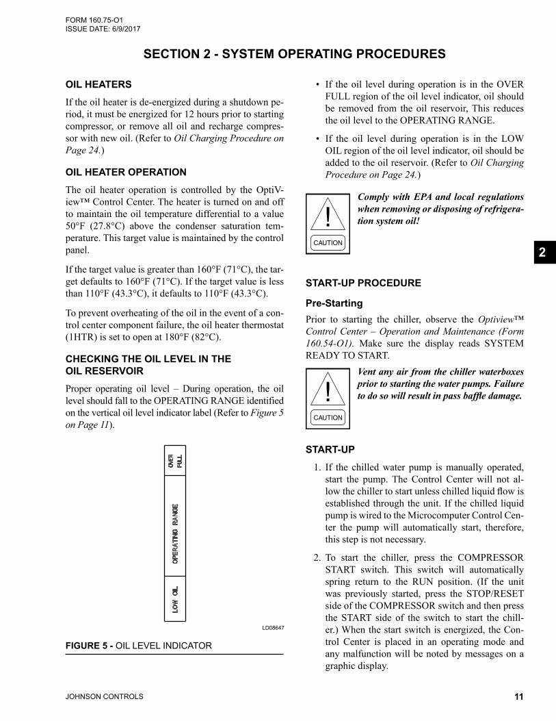
• If the oil level during operation is in the OVER FULL region of the oil level indicator, oil should be removed from the oil reservoir, This reduces the oil level to the OPERATING RANGE.
• If the oil level during operation is in the LOW OIL region of the oil level indicator, oil should be added to the oil reservoir. (Refer to Oil Charging Procedure on Page 24.)
Comply with EPA and local regulations when removing or disposing of refrigera-tion system oil!
START-UP PROCEDURE
Pre-StartingPrior to starting the chiller, observe the Optiview™ Control Center – Operation and Maintenance (Form 160.54-O1). Make sure the display reads SYSTEM READY TO START.
Vent any air from the chiller waterboxes prior to starting the water pumps. Failure to do so will result in pass baffle damage.
START-UP1. If the chilled water pump is manually operated,
start the pump. The Control Center will not al-lowthechillertostartunlesschilledliquidflowisestablished through the unit. If the chilled liquid pump is wired to the Microcomputer Control Cen-ter the pump will automatically start, therefore, this step is not necessary.
2. To start the chiller, press the COMPRESSOR START switch. This switch will automatically spring return to the RUN position. (If the unit was previously started, press the STOP/RESET side of the COMPRESSOR switch and then press the START side of the switch to start the chill-er.) When the start switch is energized, the Con-trol Center is placed in an operating mode and any malfunction will be noted by messages on a graphic display.
SECTION 2 - SYSTEM OPERATING PROCEDURES
OIL HEATERSIf the oil heater is de-energized during a shutdown pe-riod, it must be energized for 12 hours prior to starting compressor, or remove all oil and recharge compres-sor with new oil. (Refer to Oil Charging Procedure on Page 24.)
OIL HEATER OPERATIONThe oil heater operation is controlled by the OptiV-iew™ Control Center. The heater is turned on and off to maintain the oil temperature differential to a value 50°F (27.8°C) above the condenser saturation tem-perature. This target value is maintained by the control panel.
If the target value is greater than 160°F (71°C), the tar-get defaults to 160°F (71°C). If the target value is less than 110°F (43.3°C), it defaults to 110°F (43.3°C).
To prevent overheating of the oil in the event of a con-trol center component failure, the oil heater thermostat (1HTR) is set to open at 180°F (82°C).
CHECKING THE OIL LEVEL IN THE OIL RESERVOIRProper operating oil level – During operation, the oil level should fall to the OPERATING RANGE identified on the vertical oil level indicator label (Refer to Figure 5 on Page 11).
FIGURE 5 - OIL LEVEL INDICATOR
LD08647
2
JOHNSON CONTROLS12
FORM 160.75-O1 ISSUE DATE: 6/9/2017SECTION 2 - SYSTEM OPERATING PROCEDURES
LD15609
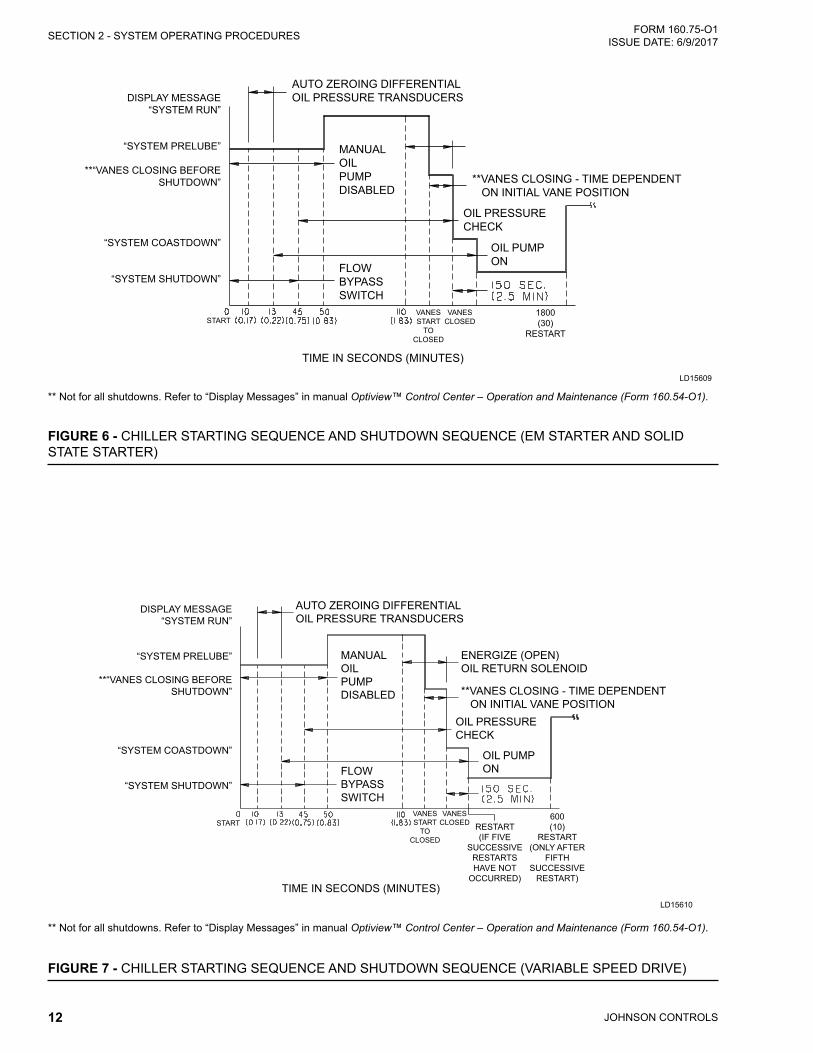
FIGURE 6 - CHILLER STARTING SEQUENCE AND SHUTDOWN SEQUENCE (EM STARTER AND SOLID STATE STARTER)
AUTO ZEROING DIFFERENTIALOIL PRESSURE TRANSDUCERSDISPLAY MESSAGE
“SYSTEM RUN”
“SYSTEM PRELUBE”
**“VANES CLOSING BEFORE SHUTDOWN”
“SYSTEM COASTDOWN”
“SYSTEM SHUTDOWN”
OIL PRESSURE CHECK
OIL PUMPON
MANUAL OILPUMPDISABLED
TIME IN SECONDS (MINUTES)
1800(30)
RESTART
VANESSTART
TOCLOSED
VANESCLOSEDSTART
**VANES CLOSING - TIME DEPENDENT ON INITIAL VANE POSITION
FLOWBYPASSSWITCH
** Not for all shutdowns. Refer to “Display Messages” in manual Optiview™ Control Center – Operation and Maintenance (Form 160.54-O1).
FIGURE 7 - CHILLER STARTING SEQUENCE AND SHUTDOWN SEQUENCE (VARIABLE SPEED DRIVE)
DISPLAY MESSAGE“SYSTEM RUN”
“SYSTEM PRELUBE”
**“VANES CLOSING BEFORE SHUTDOWN”
“SYSTEM COASTDOWN”
“SYSTEM SHUTDOWN”
TIME IN SECONDS (MINUTES)
RESTART (IF FIVE
SUCCESSIVE RESTARTS HAVE NOT
OCCURRED)
600(10)
RESTART (ONLY AFTER
FIFTH SUCCESSIVE
RESTART)
VANESSTART
TOCLOSED
VANESCLOSEDSTART
MANUAL OILPUMPDISABLED
FLOWBYPASSSWITCH
AUTO ZEROING DIFFERENTIALOIL PRESSURE TRANSDUCERS
OIL PRESSURE CHECK
OIL PUMPON
**VANES CLOSING - TIME DEPENDENT ON INITIAL VANE POSITION
ENERGIZE (OPEN)OIL RETURN SOLENOID
** Not for all shutdowns. Refer to “Display Messages” in manual Optiview™ Control Center – Operation and Maintenance (Form 160.54-O1).
LD15610
JOHNSON CONTROLS 13
SECTION 2 - SYSTEM OPERATING PROCEDURESFORM 160.75-O1 ISSUE DATE: 6/9/2017
For display messages and information pertaining to the operation refer to Optiview™ Control Center – Opera-tion and Maintenance (Form 160.54-O1).
Any malfunctions which occur during STOP/RESET are also displayed.
CHILLER OPERATIONThe unit capacity will vary to maintain the leaving CHILLED LIQUID TEMPERATURE setpoint by the Pre-rotation Vanes which are modulated by an actua-tor under the control of the Microprocessor Board. The vane control routine employs proportional plus deriva-tive (rate) control action. A drop in chilled liquid tem-perature will cause the actuator to close the Prerotation Vanes to decrease chiller capacity. When the chilled liquid temperature rises, the actuator will open the Pre-rotation Vanes to increase the capacity of the chiller.
However, the current draw (amperes) by the compres-sor motor is also limited to FLA setpoint by the micro-processor.
If the load continues to decrease, after the Prerotation Vanes are entirely closed, the chiller will be shut down by the Leaving Chilled Liquid – Low Temperature Control.
The coolant temperature inside any JCI-supplied liq-uid-cooled motor starter must be maintained above the dewpoint temperature in the equipment room to pre-vent condensing water vapor inside the starter cabinet. Therefore, an additional temperature-controlled throttle valve is needed in the flow path for the starter heat ex-changer to regulate cooling above the equipment room dewpoint for applications using cooling sources other than evaporative air-exchange methods, such as wells, bodies of water, and chilled water. The temperature control valve should be the type to open on increasing drive coolant temperature, fail-closed, and set for a tem-perature above dewpoint. It can be requested as factory- supplied on a chiller order by special quotation.
CONDENSER WATER TEMPERATURE CONTROLThe YORK chiller is designed to use less power by tak-ing advantage of lower than design temperatures that are naturally produced by cooling towers throughout the operating year. Exact control of condenser water
such as a cooling tower bypass, is not necessary for most installations. The minimum entering condenser water temperature for full and part load conditions is specified in the chiller engineering guide.
where:
Min. ECWT = LCWT – C RANGE + 5ºF + 12 ( )
Min. ECWT = LCWT – C RANGE + 2.8ºC + 6.6 ( )
ECWT = Entering Condensing Water Temperature
LCWT = Leaving Chilled Water Temperature
C Range = Condensing water temperature range at the given load condition.
% Load100
% Load100
At start-up, the entering condenser water temperature may be as much as 25°F (14°C) colder than the stand-by return chilled water temperature. Cooling tower fan cycling will normally provide adequate control of the entering condenser water temperature on most instal-lations.
Heat recovery chillers and chillers using optional head pressure control would use a signal provided by the microprocessor to control main condenser bundle heat rejection or pressure, respectively.
OPERATING LOG SHEETA permanent daily record of system operating condi-tions (temperatures and pressures) recorded at regular intervals throughout each 24 hour operating period should be kept.
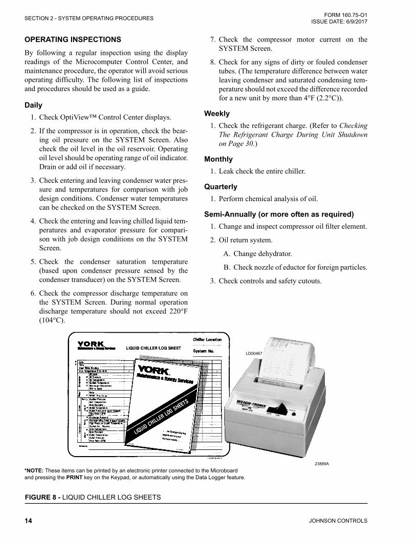
An optional status printer is available for this purpose or Figure 8 on Page 14 shows a log sheet used by Johnson Controls Personnel for recording test data on chiller systems. It is available from the factory in pads of 50 sheets each under Form 160.44-F7 and may be obtained through the nearest Johnson Controls office. Automatic data logging is possible by connecting the optional printer and programming the DATA LOG-GER function.
An accurate record of readings serves as a valuable ref-erence for operating the system. Readings taken when a system is newly installed will establish normal condi-tions with which to compare later readings.
For example, an increase in condenser approach tem-perature (condenser temperature minus leaving con-denser water temperature) may be an indication of dirty condenser tubes.
2
JOHNSON CONTROLS14
FORM 160.75-O1 ISSUE DATE: 6/9/2017SECTION 2 - SYSTEM OPERATING PROCEDURES
OPERATING INSPECTIONSBy following a regular inspection using the display readings of the Microcomputer Control Center, and maintenance procedure, the operator will avoid serious operating difficulty. The following list of inspections and procedures should be used as a guide.
Daily1. Check OptiView™ Control Center displays.
2. If the compressor is in operation, check the bear-ing oil pressure on the SYSTEM Screen. Also check the oil level in the oil reservoir. Operating oil level should be operating range of oil indicator. Drain or add oil if necessary.
3. Check entering and leaving condenser water pres-sure and temperatures for comparison with job design conditions. Condenser water temperatures can be checked on the SYSTEM Screen.
4. Check the entering and leaving chilled liquid tem-peratures and evaporator pressure for compari-son with job design conditions on the SYSTEM Screen.
5. Check the condenser saturation temperature (based upon condenser pressure sensed by the condenser transducer) on the SYSTEM Screen.
6. Check the compressor discharge temperature on the SYSTEM Screen. During normal operation discharge temperature should not exceed 220°F (104°C).
7. Check the compressor motor current on the SYSTEM Screen.
8. Check for any signs of dirty or fouled condenser tubes. (The temperature difference between water leaving condenser and saturated condensing tem-perature should not exceed the difference recorded for a new unit by more than 4°F (2.2°C)).
Weekly1. Check the refrigerant charge. (Refer to Checking
The Refrigerant Charge During Unit Shutdown on Page 30.)
Monthly1. Leak check the entire chiller.
Quarterly1. Perform chemical analysis of oil.
Semi-Annually (or more often as required)1. Changeandinspectcompressoroilfilterelement.
2. Oil return system.
A. Change dehydrator.
B. Check nozzle of eductor for foreign particles.
3. Check controls and safety cutouts.
FIGURE 8 - LIQUID CHILLER LOG SHEETS
*NOTE: These items can be printed by an electronic printer connected to the Microboard and pressing the PRINT key on the Keypad, or automatically using the Data Logger feature.
LD00467
23889A
JOHNSON CONTROLS 15
SECTION 2 - SYSTEM OPERATING PROCEDURESFORM 160.75-O1 ISSUE DATE: 6/9/2017
2
Annually (more often if necessary)1. Drain and replace the oil in the compressor oil
sump. (Refer to Oil Charging Procedure on Page 24.)
2. Evaporator and Condenser.
A. Inspect and clean water strainers.
B. Inspect and clean tubes as required.
C. Inspect end sheets.
3. Compressor Drive Motor (See motor manufactur-ers maintenance and service instruction supplied with unit)
A. Clean air passages and windings per manu-facturers instructions.
B. Meg motor windings – Refer to Figure 16 on Page 30 for details.
C. Lubricate per motor manufacturer recom-mendations.
4. Inspect and service electrical components as neces-sary.
5. Perform refrigerant analysis.If quarterly inspection indicates oil is fine, replacing the oil is not necessary
NEED FOR MAINTENANCE OR SERVICEIf the system is malfunctioning in any manner or the unit is stopped by one of the safety controls, consult the Operation Analysis Chart, Table 1 on Page 25 of this manual. After consulting this chart, if you are un-able to make the proper repairs or adjustments to start the compressor or the particular trouble continues to hinder the performance of the unit, please call the near-est Johnson Controls District Office. Failure to report constant troubles could damage the unit and increase the cost of repairs.
STOPPING THE SYSTEMThe Optiview™ Control Center can be programmed to start and stop automatically (maximum, once each day) whenever desired. Refer to the Optiview™ Control Center – Operation and Maintenance (Form 160.54-O1). To stop the chiller, proceed as follows:
1. Push the soft shutdown key on the homescreen on the OptiView panel or rapid stop with the COM-PRESSOR STOP/RESET switch. The compressor will stop automatically. The oil pump will contin-ue to run for coastdown period. The oil pump will then stop automatically.
2. Stop the chilled water pump (if not wired into the Microcomputer Control Center, in which case it will shut off automatically simultaneously with the oil pump.) (The actual water pump contact opera-tion is dependent upon the position of Microboard jumper J54.)
3. Open the switch to the cooling tower fan motors, if used.
4. The compressor sump oil heater is energized when the unit is stopped.
PROLONGED SHUTDOWNIf the chiller is to be shut down for an extended period of time (for example, over the winter season), the fol-lowing paragraphs outline the procedure to be followed.
1. Test all system joints for refrigerant leaks with a leak detector. If any leaks are found, they should be repaired before allowing the system to stand for a long period of time.
During long idle periods, the tightness of the sys-tem should be checked periodically.
2. If freezing temperatures are encountered while the system is idle, carefully drain the cooling wa-ter from the cooling tower, condenser, condenser pump, and the chilled water system-chilled water pump and coils.
Open the drains on the evaporator and condenser liquid heads to assure complete drainage. (If a Variable Speed Drive, drain its cooling system. If Solid State Starter equipped drain liquid from starter cooling loop.)
3. If freezing temperatures are encountered for peri-ods longer than a few days, the refrigerant should be recovered to containers to prevent leakage from O-ring joints.
4. On the SETUP Screen, disable the clock. This conserves the battery.
5. Open the main disconnect switches to the com-pressor motor, condenser water pump and the chilled water pump. Open the 115 volt circuit to the Control Center.

JOHNSON CONTROLS16
FORM 160.75-O1 ISSUE DATE: 6/9/2017
THIS PAGE INTENTIONALLY LEFT BLANK
JOHNSON CONTROLS 17
FORM 160.75-O1 ISSUE DATE: 6/9/2017
SECTION 3 - SYSTEM COMPONENTS DESCRIPTION
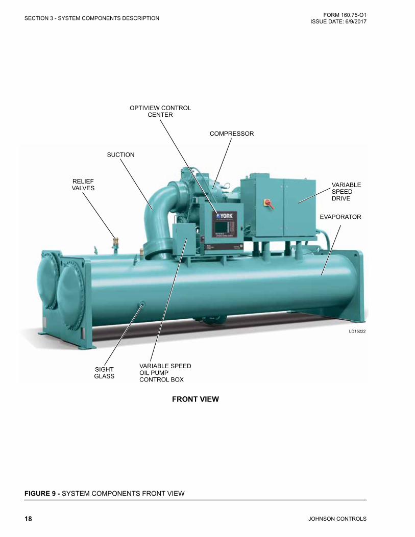
GENERALThe YORK Model YK Centrifugal Liquid Chiller is completely factory-packaged including evaporator, condenser, compressor, motor, lubrication system, OptiView Control Center, and all interconnecting unit piping and wiring.
COMPRESSORThe compressor is a single-stage centrifugal type pow-ered by an open-drive electric motor.
The rotor assembly consists of a heat-treated alloy steel drive shaft and impeller shaft with a cast aluminum, fully shrouded impeller. The impeller is designed for balanced thrust and is dynamically balanced and over-speed tested. The inserted type journal and thrust bear-ings are fabricated of aluminum alloy. Single helical gears with crowned teeth are designed so that more than one tooth is in contact at all times. Gears are inte-grally assembled in the compressor rotor support and are film lubricated. Each gear is individually mounted in its own journal and thrust bearings.
The open-drive compressor shaft seal is a double bel-lows cartridge style with ceramic internal and atmo-spheric seal faces. The seal is oil-flooded at all times and is pressure-lubricated during operation.
CAPACITY CONTROLPrerotation vanes (PRV) modulate chiller capacity from 100% to as low as 15% of design for normal air conditioning applications. Operation is by an external, electric PRV actuator which automatically controls the vane position to maintain a constant leaving chilled liq-uid temperature.
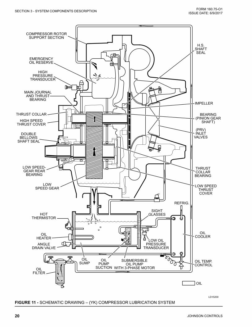
COMPRESSOR LUBRICATION SYSTEM The chiller lubrication system consists of the oil pump, oil filter, oil cooler and all interconnecting oil piping and passages. There are main points within the com-pressor which must be supplied with forced lubrication as follows:
1. Compressor Drive Shaft (Low Speed)
A. Shaft seal.
B. Front and rear journal bearings – one on each side of driving gear.
C. Low speed thrust bearing (forward and re-verse).
2. Compressor Driven Shaft (High Speed)
A. Forward and reverse high speed thrust bearing.
B. Two journal bearings.
3. Speed Increasing Gears
A. Meshing surfaces of drive and pinion gear teeth.
To provide the required amount of oil under the neces-sary pressure to properly lubricate these parts, a motor driven submersible oil pump is located in a remote oil sump.
Upon pressing of the COMPRESSOR START switch on the Control Center, the oil pump is immediately en-ergized. After a 50 second pre-lube period, the com-pressor motor will start. The oil pump will continue to run during the entire operation of the compressor, and for 150 seconds during compressor coastdown.
The submerged oil pump takes suction from the sur-rounding oil and discharges it to the oil cooler where heat is rejected. The oil flows from the oil cooler to the oil filter. The oil leaves the filter and flows to the emergency oil reservoir where it is distributed to the compressor bearings. The oil lubricates the compressor rotating components and is returned to the oil sump.
There is an emergency oil reservoir located at the high-est point in the lubrication system internally in the com-pressor. It provides an oil supply to the various bear-ings and gears in the event of a system shutdown due to power failure. The reservoir, located on the top of the compressor, allows the oil to be distributed through the passages by gravity flow, thus providing necessary lubrication during the compressor coastdown.
OIL PUMPFor normal operation, the oil pump should operate at all times during chiller operation.
On shutdown of the system for any reason, the oil pump operates and continues to run for 150 seconds. The system cannot restart during that time interval.
3
JOHNSON CONTROLS18
FORM 160.75-O1 ISSUE DATE: 6/9/2017SECTION 3 - SYSTEM COMPONENTS DESCRIPTION
FRONT VIEW
FIGURE 9 - SYSTEM COMPONENTS FRONT VIEW
VARIABLE SPEED DRIVE
EVAPORATOR
COMPRESSOR
SUCTION
RELIEF VALVES
SIGHT GLASS
VARIABLE SPEED OIL PUMP CONTROL BOX
OPTIVIEW CONTROL CENTER
LD15222
JOHNSON CONTROLS 19
SECTION 3 - SYSTEM COMPONENTS DESCRIPTIONFORM 160.75-O1 ISSUE DATE: 6/9/2017
3
LD15223
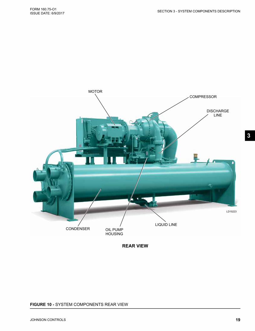
FIGURE 10 - SYSTEM COMPONENTS REAR VIEW
DISCHARGE LINE
COMPRESSOR
OIL PUMP HOUSING
LIQUID LINE
REAR VIEW
MOTOR
CONDENSER
JOHNSON CONTROLS20
FORM 160.75-O1 ISSUE DATE: 6/9/2017SECTION 3 - SYSTEM COMPONENTS DESCRIPTION
HOTTHERMISTOR
OILHEATER
ANGLEDRAIN VALVE
OILFILTER
OILSUMP
OILPUMP
SUCTION
SUBMERSIBLEOIL PUMP
WITH 3-PHASE MOTOR
LOW OIL PRESSURE
TRANSDUCER
SIGHTGLASSES
OILCOOLER
OIL TEMP.CONTROL
REFRIG.
THRUSTCOLLAR BEARING
(PRV)INLET
VALVES
BEARING(PINION GEAR
SHAFT)
IMPELLER
H.S.SHAFTSEAL
LOW SPEEDTHRUSTCOVER
LOWSPEED GEAR
LOW SPEED-GEAR REAR
BEARING
DOUBLEBELLOWS
SHAFT SEAL
HIGH SPEEDTHRUST COVER
THRUST COLLAR
MAIN JOURNALAND THRUST
BEARING
HIGH PRESSURE
TRANSDUCER
EMERGENCYOIL RESERVE
COMPRESSOR ROTORSUPPORT SECTION
OIL
FIGURE 11 - SCHEMATIC DRAWING – (YK) COMPRESSOR LUBRICATION SYSTEMLD15200
JOHNSON CONTROLS 21
SECTION 3 - SYSTEM COMPONENTS DESCRIPTIONFORM 160.75-O1 ISSUE DATE: 6/9/2017
OIL HEATERDuring long idle periods, the oil in the compressor oil reservoir tends to absorb as much refrigerant as it can hold, depending upon the temperature of the oil and the pressure in the reservoir. As the oil temperature is lowered, the amount of refrigerant absorbed will be increased. If the quantity of refrigerant in the oil be-comes excessive, violent oil foaming will result as the pressure within the system is lowered on starting. This foaming is caused by refrigerant boiling out of the oil as the pressure is lowered. If this foam reaches the oil pump suction, the bearing oil pressure will fluctuate with possible temporary loss of lubrication, causing the oil pressure safety cutout to actuate and stop the sys-tem. Refer to Optiview™ Control Center – Operation and Maintenance (Form 160.54-O1).
MOTOR DRIVELINEThe compressor motor is an open-drip-proof, squir-rel cage, induction type constructed to YORK design specifications. 60 hertz motors operate at 3570 rpm. 50 hertz motors operate at 2975 rpm.
The open motor is provided with a D-flange, cast iron adapter mounted to the compressor and supported by a motor support.
Motor drive shaft is directly connected to the compres-sor shaft with a flexible disc coupling. This coupling has all metal construction with no wearing parts to as-sure long life, and no lubrication requirements to pro-vide low maintenance.
For units utilizing remote Electro-Mechanical starters, a terminal box is provided for field connected conduit. Motor terminals are brought through the motor cas-ing into the terminal box. Jumpers are furnished for three-lead type of starting. Motor terminal lugs are not furnished. Overload/over current transformers are fur-nished with all units.
HEAT EXCHANGERSEvaporator and condenser shells are fabricated from rolled carbon steel plates with fusion welded seams.
Heat exchanger tubes are internally enhanced type.
The evaporator is a shell and tube type with customer process fluid flowing inside the tubes and refriger-ant removing heat on the shell side via evaporation. Evaporator codes A* to K* utilize a hybrid falling film design. It contains a balance of flooded and falling film technology to optimize efficiency, minimize refriger-
ant charge, and maintain reliable control. A specifically designed spray distributor provides uniform distribu-tion of refrigerant over the entire length to yield opti-mum heat transfer. The hybrid falling film evaporator design has suction baffles around the sides and above the falling film section to prevent liquid refrigerant car-ryover into the compressor.
Evaporators codes M* thru Z* are flooded type, with a liquid inlet distributor trough underneath the tube bun-dle which provides uniform distribution of refrigerant over the entire shell length to yield optimum heat trans-fer. Flooded evaporator designs have a suction baffle on M* shells with H9 compressors and an aluminum mesh eliminator on K* - Z* shells with K compressors located above the tube bundle to prevent liquid refrig-erant carryover into the compressor.
A 1-1/2" (38 mm) liquid level sight glass is conve-niently located on the side of the shell to aid in deter-mining proper refrigerant charge. The evaporator shell contains a dual refrigerant relief valve arrangement set at 180 psig (12.4 barg) on H and K compressor models; 235 psig (16.2 barg) on P and Q compressor models; or single-relief valve arrangement, if the chiller is sup-plied with optional refrigerant isolation valves. A 1" (25.4 mm) refrigerant charging valve is provided. The condenser is a shell and tube type, with a discharge gas baffle to prevent direct high velocity impingement on the tubes. The baffle is also used to distribute the refrigerant gas flow properly for most efficient heat transfer. An optional cast steel condenser inlet diffuser may be offered, on "M" and larger condensers, in lieu of the baffle, to provide dynamic pressure recovery and enhanced chiller efficiency. An integral sub-cooler is located at the bottom of the condenser shell providing highly effective liquid refrigerant subcooling to pro-vide the highest cycle efficiency. The condenser con-tains dual refrigerant relief valves set at 235 psig (16.2 barg).
The removable waterboxes are fabricated of steel. The design working pressure is 150 psig (10.3 barg) and the boxes are tested at 225 psig (15.5 barg). Integral steel water baffles are located and welded within the waterbox to provide the required pass arrangements. Stub-out water nozzle connections with ANSI/AWWA C-606 grooves are welded to the waterboxes. These nozzle connections are suitable for ANSI/AWWA C-606 couplings, welding or flanges, and are capped for shipment. Plugged 3/4" (19 mm) drain and vent connections are provided in each waterbox.
3
JOHNSON CONTROLS22
FORM 160.75-O1 ISSUE DATE: 6/9/2017SECTION 3 - SYSTEM COMPONENTS DESCRIPTION
REFRIGERANT FLOW CONTROLRefrigerant flow to the evaporator is controlled by a variable orifice.
A level sensor senses the refrigerant level in the con-denser and outputs an analog voltage to the Microboard that represents this level (0% = empty; 100% = full). Under program control, the Microboard modulates a variable orifice to control the condenser refrigerant level to a programmed setpoint. Other setpoints affect the control sensitivity and response. These setpoints must be entered at chiller commissioning by a qualified service technician. Only a qualified service technician may modify these settings.
While the chiller is shut down, the orifice will be in the fully open position causing the sensed level to be ap-proximately 0%. When the chiller is started, after the vane motor end switch (VMS) opens when entering SYSTEM RUN, if actual level is less than the level setpoint, a linearly increasing ramp is applied to the lev-el setpoint. This ramp causes the setpoint to go from the initial refrigerant level (approximately 0%) to the pro-grammed setpoint over a programmable period of time.
If the actual level is greater than the setpoint when the VMS opens, there is no pulldown period, it immedi-ately begins to control to the programmed setpoint.
While the chiller is running, the refrigerant level is nor-mally controlled to the level setpoint. However, any-time the vanes fully close (VMS closes), normal level control is terminated, any refrigerant level setpoint in effect is cancelled and the outputs to the level control will be constant open.
OPTIONAL SERVICE ISOLATION VALVESIf your chiller is equipped with optional service isola-tion valves on the discharge and liquid line, these valves must remain open during operation. These valves are used for isolating the refrigerant charge in either the evaporator or condenser to allow service access to the system. A refrigerant pump-out unit will be required to isolate the refrigerant.
Isolation of the refrigerant in this system must be performed by a qualified service technician.
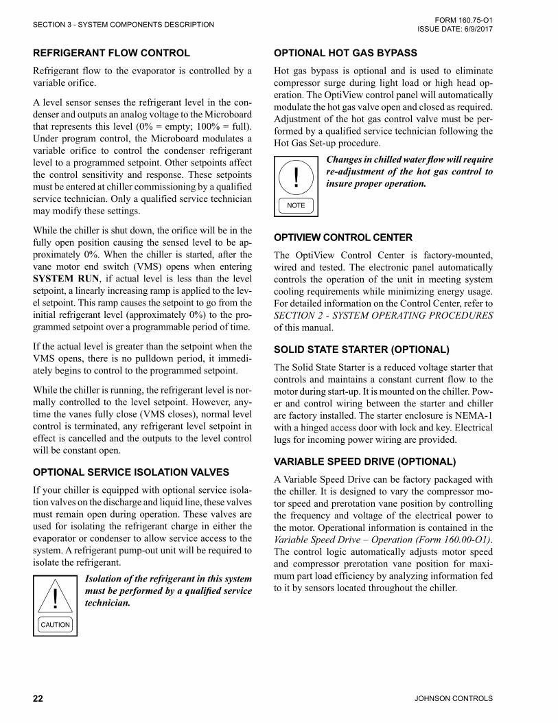
OPTIONAL HOT GAS BYPASSHot gas bypass is optional and is used to eliminate compressor surge during light load or high head op-eration. The OptiView control panel will automatically modulate the hot gas valve open and closed as required. Adjustment of the hot gas control valve must be per-formed by a qualified service technician following the Hot Gas Set-up procedure.
Changes in chilled water flow will require re-adjustment of the hot gas control to insure proper operation.
OPTIVIEW CONTROL CENTERThe OptiView Control Center is factory-mounted, wired and tested. The electronic panel automatically controls the operation of the unit in meeting system cooling requirements while minimizing energy usage. For detailed information on the Control Center, refer to SECTION 2 - SYSTEM OPERATING PROCEDURES of this manual.
SOLID STATE STARTER (OPTIONAL)The Solid State Starter is a reduced voltage starter that controls and maintains a constant current flow to the motor during start-up. It is mounted on the chiller. Pow-er and control wiring between the starter and chiller are factory installed. The starter enclosure is NEMA-1 with a hinged access door with lock and key. Electrical lugs for incoming power wiring are provided.
VARIABLE SPEED DRIVE (OPTIONAL)A Variable Speed Drive can be factory packaged with the chiller. It is designed to vary the compressor mo-tor speed and prerotation vane position by controlling the frequency and voltage of the electrical power to the motor. Operational information is contained in the Variable Speed Drive – Operation (Form 160.00-O1). The control logic automatically adjusts motor speed and compressor prerotation vane position for maxi-mum part load efficiency by analyzing information fed to it by sensors located throughout the chiller.
JOHNSON CONTROLS 23
FORM 160.75-O1 ISSUE DATE: 6/9/2017
SECTION 4 - OPERATIONAL MAINTENANCE
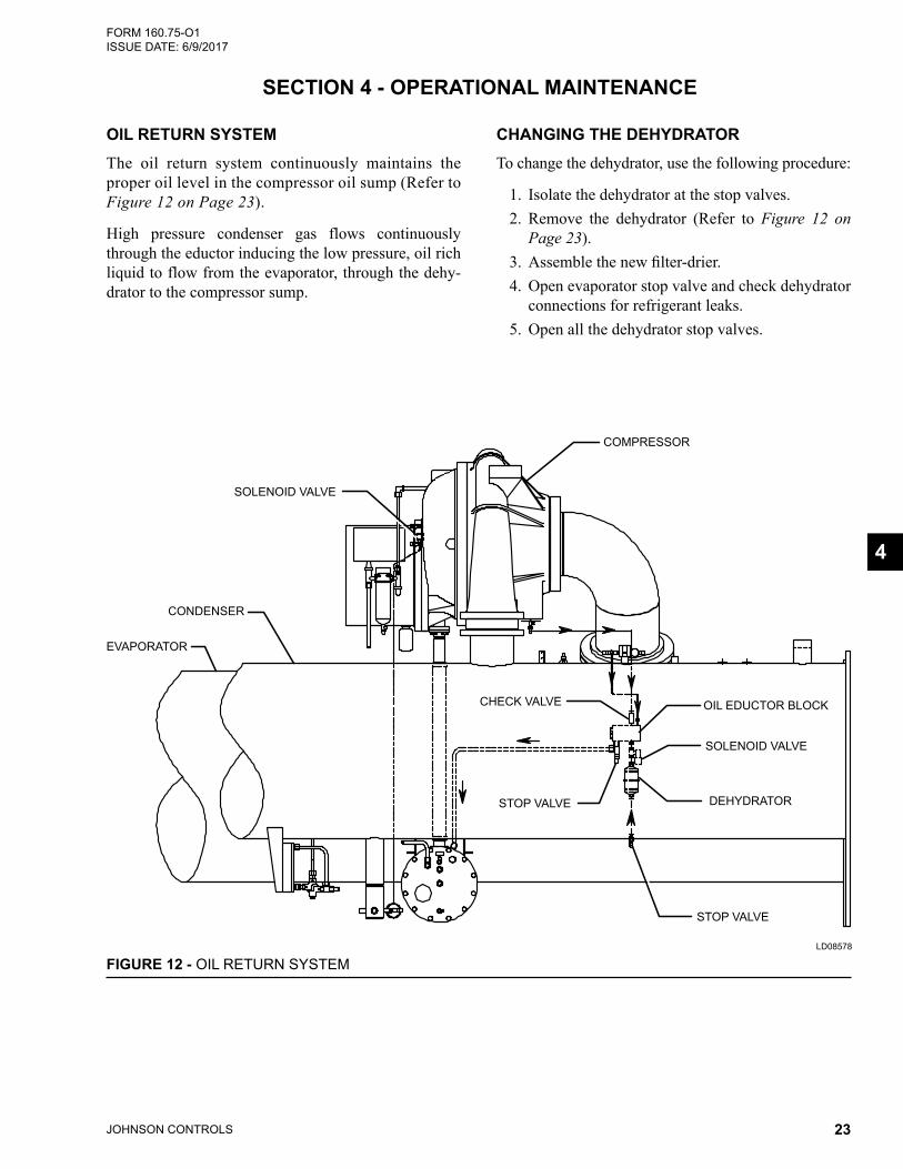
OIL RETURN SYSTEMThe oil return system continuously maintains the proper oil level in the compressor oil sump (Refer to Figure 12 on Page 23).
High pressure condenser gas flows continuously through the eductor inducing the low pressure, oil rich liquid to flow from the evaporator, through the dehy-drator to the compressor sump.
CHANGING THE DEHYDRATORTo change the dehydrator, use the following procedure:
1. Isolate the dehydrator at the stop valves.2. Remove the dehydrator (Refer to Figure 12 on
Page 23).3. Assemblethenewfilter-drier.4. Open evaporator stop valve and check dehydrator
connections for refrigerant leaks.5. Open all the dehydrator stop valves.
4
OIL EDUCTOR BLOCK
SOLENOID VALVE
SOLENOID VALVE
CONDENSER
EVAPORATOR
DEHYDRATOR
STOP VALVE
STOP VALVE
CHECK VALVE
COMPRESSOR
FIGURE 12 - OIL RETURN SYSTEMLD08578
JOHNSON CONTROLS24
FORM 160.75-O1 ISSUE DATE: 6/9/2017SECTION 4 - OPERATIONAL MAINTENANCE
THE OIL CHARGEThe nominal oil charge for H, K*, and P8-P9 YK com-pressors is 17.5 gallons. K7 compressors on flooded shell units require 24 gallons of YORK K oil. Q3-Q7 YK compressors require 11 gallons of YORK K or YORK H oil (depending on ambient temperatures).
New YORK Refrigeration oil must be used in the cen-trifugal compressor. Since oil absorbs moisture when exposed to the atmosphere, it should be kept tightly capped until used.
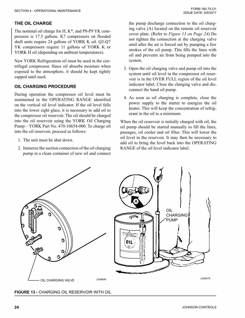
OIL CHARGING PROCEDUREDuring operation the compressor oil level must be maintained in the OPERATING RANGE identified on the vertical oil level indicator. If the oil level falls into the lower sight glass, it is necessary to add oil to the compressor oil reservoir. The oil should be charged into the oil reservoir using the YORK Oil Charging Pump – YORK Part No. 470-10654-000. To charge oil into the oil reservoir, proceed as follows:
1. The unit must be shut down.
2. Immerse the suction connection of the oil charging pump in a clean container of new oil and connect
the pump discharge connection to the oil charg-ing valve (A) located on the remote oil reservoir cover plate. (Refer to Figure 13 on Page 24) Do not tighten the connection at the charging valve until after the air is forced out by pumping a few strokesof theoilpump.Thisfills the lineswithoil and prevents air from being pumped into the system.
3. Open the oil charging valve and pump oil into the system until oil level in the compressor oil reser-voir is in the OVER FULL region of the oil level indicator label. Close the charging valve and dis-connect the hand oil pump.
4. As soon as oil charging is complete, close the power supply to the starter to energize the oil heater. This will keep the concentration of refrig-erant in the oil to a minimum.
When the oil reservoir is initially charged with oil, the oil pump should be started manually to fill the lines, passages, oil cooler and oil filter. This will lower the oil level in the reservoir. It may then be necessary to add oil to bring the level back into the OPERATING RANGE of the oil level indicator label.
FIGURE 13 - CHARGING OIL RESERVOIR WITH OIL
OIL CHARGING PUMP
LD08579LD08648OIL CHARGING VALVE
JOHNSON CONTROLS 25
FORM 160.75-O1 ISSUE DATE: 6/9/2017
SECTION 5 - TROUBLESHOOTING
5
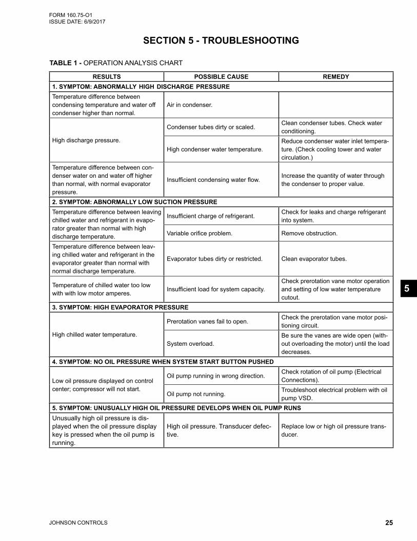
TABLE 1 - OPERATION ANALYSIS CHART
RESULTS POSSIBLE CAUSE REMEDY1. SYMPTOM: ABNORMALLY HIGH DISCHARGE PRESSURETemperature difference between condensing temperature and water off condenser higher than normal.
Air in condenser.
High discharge pressure.
Condenser tubes dirty or scaled.Clean condenser tubes. Check water conditioning.
High condenser water temperature.Reduce condenser water inlet tempera-ture. (Check cooling tower and water circulation.)
Temperature difference between con-denser water on and water off higher than normal, with normal evaporator pressure.
Insufficient condensing water flow.Increase the quantity of water through the condenser to proper value.
2. SYMPTOM: ABNORMALLY LOW SUCTION PRESSURETemperature difference between leaving chilled water and refrigerant in evapo-rator greater than normal with high discharge temperature.
Insufficient charge of refrigerant.Check for leaks and charge refrigerant into system.
Variable orifice problem. Remove obstruction.
Temperature difference between leav-ing chilled water and refrigerant in the evaporator greater than normal with normal discharge temperature.
Evaporator tubes dirty or restricted. Clean evaporator tubes.
Temperature of chilled water too low with with low motor amperes.
Insufficient load for system capacity.Check prerotation vane motor operation and setting of low water temperature cutout.
3. SYMPTOM: HIGH EVAPORATOR PRESSURE
High chilled water temperature.
Prerotation vanes fail to open.Check the prerotation vane motor posi-tioning circuit.
System overload.Be sure the vanes are wide open (with-out overloading the motor) until the load decreases.
4. SYMPTOM: NO OIL PRESSURE WHEN SYSTEM START BUTTON PUSHED
Low oil pressure displayed on control center; compressor will not start.
Oil pump running in wrong direction.Check rotation of oil pump (Electrical Connections).
Oil pump not running.Troubleshoot electrical problem with oil pump VSD.
5. SYMPTOM: UNUSUALLY HIGH OIL PRESSURE DEVELOPS WHEN OIL PUMP RUNSUnusually high oil pressure is dis-played when the oil pressure display key is pressed when the oil pump is running.
High oil pressure. Transducer defec-tive.
Replace low or high oil pressure trans-ducer.
JOHNSON CONTROLS26
FORM 160.75-O1 ISSUE DATE: 6/9/2017SECTION 5 - TROUBLESHOOTING
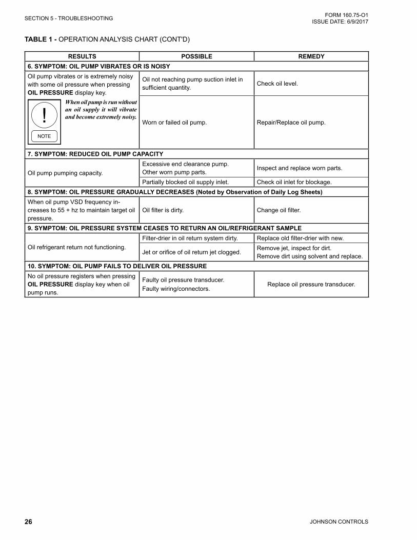
RESULTS POSSIBLE REMEDY6. SYMPTOM: OIL PUMP VIBRATES OR IS NOISYOil pump vibrates or is extremely noisy with some oil pressure when pressing OIL PRESSURE display key.
When oil pump is run without an oil supply it will vibrate and become extremely noisy.
Oil not reaching pump suction inlet in sufficient quantity.
Check oil level.
Worn or failed oil pump. Repair/Replace oil pump.
7. SYMPTOM: REDUCED OIL PUMP CAPACITY
Oil pump pumping capacity.Excessive end clearance pump. Other worn pump parts.
Inspect and replace worn parts.
Partially blocked oil supply inlet. Check oil inlet for blockage.8. SYMPTOM: OIL PRESSURE GRADUALLY DECREASES (Noted by Observation of Daily Log Sheets)When oil pump VSD frequency in-creases to 55 + hz to maintain target oil pressure.
Oil filter is dirty. Change oil filter.
9. SYMPTOM: OIL PRESSURE SYSTEM CEASES TO RETURN AN OIL/REFRIGERANT SAMPLE
Oil refrigerant return not functioning.Filter-drier in oil return system dirty. Replace old filter-drier with new.
Jet or orifice of oil return jet clogged.Remove jet, inspect for dirt. Remove dirt using solvent and replace.
10. SYMPTOM: OIL PUMP FAILS TO DELIVER OIL PRESSURENo oil pressure registers when pressing OIL PRESSURE display key when oil pump runs.
Faulty oil pressure transducer. Faulty wiring/connectors.
Replace oil pressure transducer.
TABLE 1 - OPERATION ANALYSIS CHART (CONT'D)
JOHNSON CONTROLS 27
FORM 160.75-O1 ISSUE DATE: 6/9/2017
SECTION 6 - MAINTENANCE
RENEWAL PARTSFor any required Renewal Parts, refer to the Renewal Parts – Unit (Form 160.75-RP1).
CHECKING SYSTEM FOR LEAKS
Leak Testing During OperationThe refrigerant side of the system is carefully pressure tested and evacuated at the factory.
After the system has been charged, the system should be carefully leak tested with a R-134a compatible leak detector to be sure all joints are tight.
If any leaks are indicated, they must be repaired im-mediately. Usually, leaks can be stopped by tighten-ing flare nuts or flange bolts. However, for any major repair, the refrigerant charge must be removed. (Refer to Handling Refrigerant For Dismantling And Repairs on Page 30)
CONDUCTING R-22 PRESSURE TESTWith the R-134a charge removed and all known leaks repaired, the system should be charged with a small amount of R-22 mixed with dry nitrogen so that a ha-lide torch or electronic leak detector can be used to de-tect any leaks too small to be found by the soap test.
To test with R-22, proceed as follows:
1. With no pressure in the system, charge R-22 gas into the system through the charging valve to a pressure of 2 PSIG (14 kPa).
2. Build up the system pressure with dry nitrogen to approximately 75 to 100 PSIG (517 to 690 kPa). To be sure that the concentration of refrigerant has reached all part of the system, slightly open the oil charging valve and test for the presence of refrig-erant with a leak detector.
3. Test around each joint and factory weld. It is im-portant that this test be thoroughly and carefully done, spending as much time as necessary and us-ing a good leak detector.
4. To check for refrigerant leaks in the evaporator and condenser, open the vents in the evaporator and condenser heads and test for the presence of refrigerant. If no refrigerant is present, the tubes and tube sheets may be considered tight. If refrig-erant is detected at the vents, the heads must be removed, the leak located (by means of soap test or leak detector) and repaired.
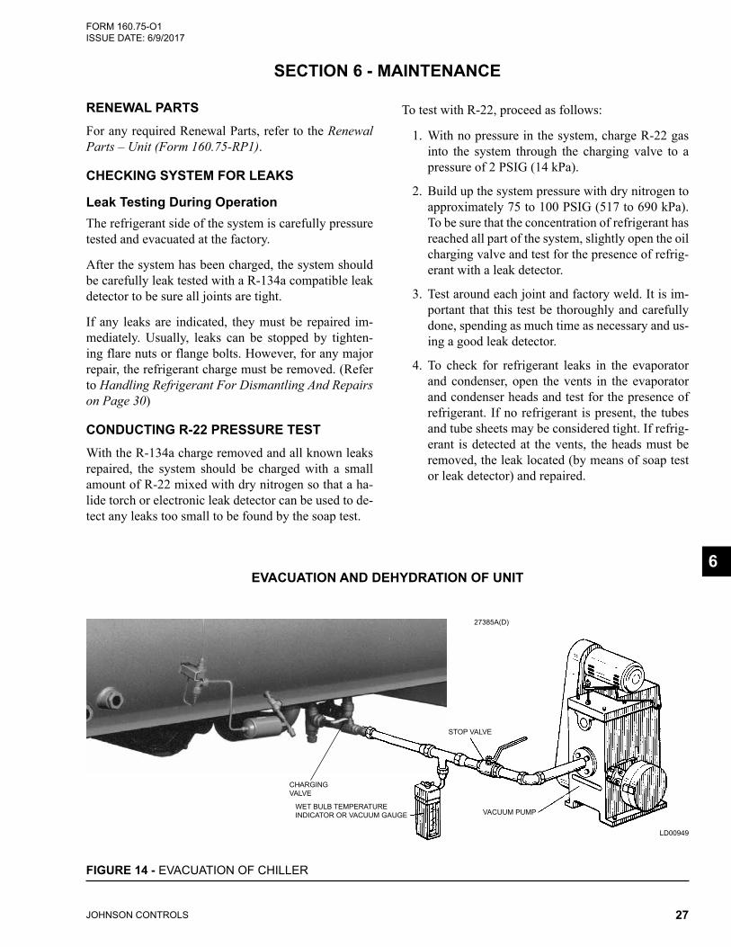
6EVACUATION AND DEHYDRATION OF UNIT
FIGURE 14 - EVACUATION OF CHILLER
27385A(D)
LD00949
STOP VALVE
CHARGING VALVE
VACUUM PUMPWET BULB TEMPERATUREINDICATOR OR VACUUM GAUGE
JOHNSON CONTROLS28
FORM 160.75-O1 ISSUE DATE: 6/9/2017SECTION 6 - MAINTENANCE
VACUUM TESTINGAfter the pressure test has been completed, the vacuum test should be conducted as follows:
1. Connect a high capacity vacuum pump, with in-dicator, to the system charging valve as shown in Figure 14 on Page 27 and start the pump. (Re-fer to Vacuum Dehydration on Page 29.)
2. Open wide all system valves. Be sure all valves to the atmosphere are closed.
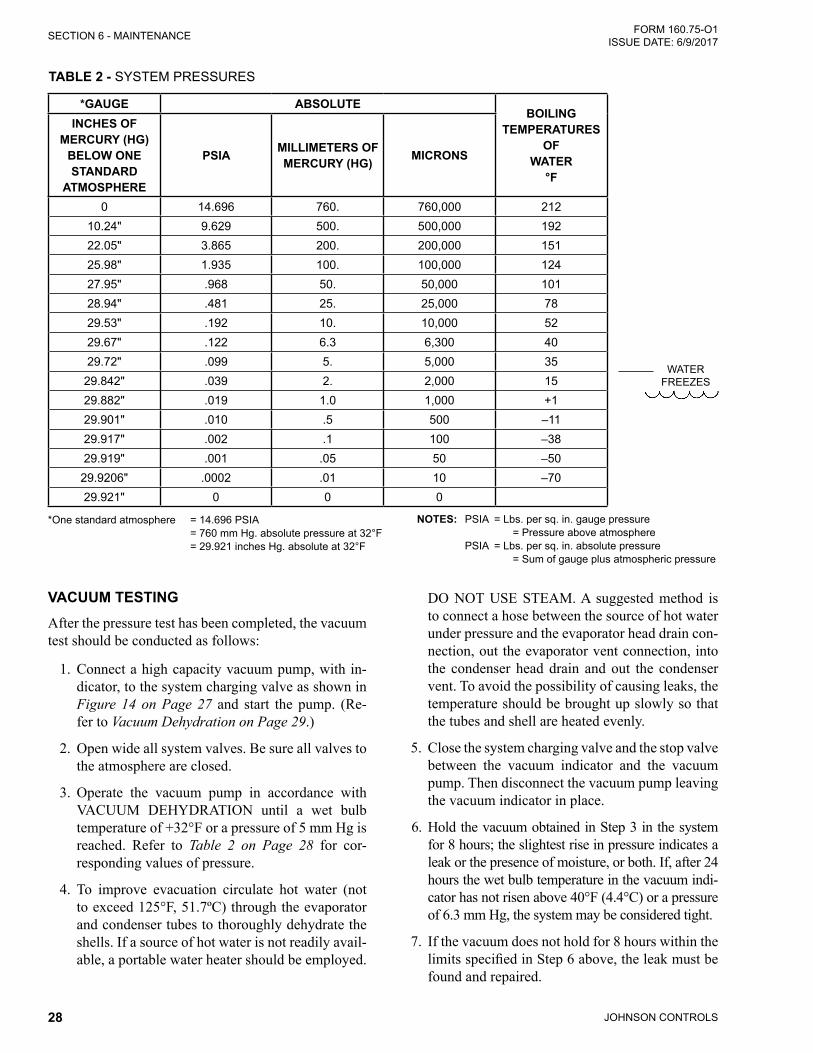
3. Operate the vacuum pump in accordance with VACUUM DEHYDRATION until a wet bulb temperature of +32°F or a pressure of 5 mm Hg is reached. Refer to Table 2 on Page 28 for cor-responding values of pressure.
4. To improve evacuation circulate hot water (not to exceed 125°F, 51.7ºC) through the evaporator and condenser tubes to thoroughly dehydrate the shells. If a source of hot water is not readily avail-able, a portable water heater should be employed.
DO NOT USE STEAM. A suggested method is to connect a hose between the source of hot water under pressure and the evaporator head drain con-nection, out the evaporator vent connection, into the condenser head drain and out the condenser vent. To avoid the possibility of causing leaks, the temperature should be brought up slowly so that the tubes and shell are heated evenly.
5. Close the system charging valve and the stop valve between the vacuum indicator and the vacuum pump. Then disconnect the vacuum pump leaving the vacuum indicator in place.
6. Hold the vacuum obtained in Step 3 in the system for 8 hours; the slightest rise in pressure indicates a leak or the presence of moisture, or both. If, after 24 hours the wet bulb temperature in the vacuum indi-cator has not risen above 40°F (4.4°C) or a pressure of 6.3 mm Hg, the system may be considered tight.
7. If the vacuum does not hold for 8 hours within the limitsspecifiedinStep6above,theleakmustbefound and repaired.
WATER FREEZES
*One standard atmosphere = 14.696 PSIA = 760 mm Hg. absolute pressure at 32°F = 29.921 inches Hg. absolute at 32°F
NOTES: PSIA = Lbs. per sq. in. gauge pressure = Pressure above atmosphere PSIA = Lbs. per sq. in. absolute pressure = Sum of gauge plus atmospheric pressure
TABLE 2 - SYSTEM PRESSURES
*GAUGE ABSOLUTEBOILING
TEMPERATURES OF
WATER °F
INCHES OF MERCURY (HG)
BELOW ONE STANDARD
ATMOSPHERE
PSIA MILLIMETERS OF MERCURY (HG) MICRONS
0 14.696 760. 760,000 21210.24" 9.629 500. 500,000 19222.05" 3.865 200. 200,000 15125.98" 1.935 100. 100,000 12427.95" .968 50. 50,000 10128.94" .481 25. 25,000 7829.53" .192 10. 10,000 5229.67" .122 6.3 6,300 4029.72" .099 5. 5,000 35
29.842" .039 2. 2,000 1529.882" .019 1.0 1,000 +129.901" .010 .5 500 –1129.917" .002 .1 100 –3829.919" .001 .05 50 –50
29.9206" .0002 .01 10 –7029.921" 0 0 0
JOHNSON CONTROLS 29
SECTION 6 - MAINTENANCEFORM 160.75-O1 ISSUE DATE: 6/9/2017
6
Be sure the vacuum indicator is valved off while holding the system vacuum and be sure to open the valve between the vacuum indicator and the system when checking the vacuum after the 8 hour period.
VACUUM DEHYDRATIONTo obtain a sufficiently dry system, the following in-structions have been assembled to provide an effective method for evacuating and dehydrating a system in the field. Although there are several methods of dehydrating a system, we are recommending the following, as it pro-duces one of the best results, and affords a means of ob-taining accurate readings as to the extent of dehydration.
The equipment required to follow this method of dehy-dration consists of a wet bulb indicator or vacuum gauge, a chart showing the relation between dew point tempera-ture and pressure in inches of mercury (vacuum), (Refer to Table 2 on Page 28) and a vacuum pump capable of pumping a suitable vacuum on the system.
OPERATIONDehydration of a refrigerant system can be obtained by this method because the water present in the system reacts much as a refrigerant would. By pulling down the pressure in the system to a point where its satu-ration temperature is considerably below that of room temperature, heat will flow from the room through the walls of the system and vaporize the water, allowing a large percentage of it to be removed by the vacuum pump. The length of time necessary for the dehydra-tion of a system is dependent on the size or volume of the system, the capacity and efficiency of the vacuum pump, the room temperature and the quantity of water present in the system. By the use of the vacuum indi-cator as suggested, the test tube will be evacuated to the same pressure as the system, and the distilled water will be maintained at the same saturation temperature as any free water in the system, and this temperature can be observed on the thermometer.
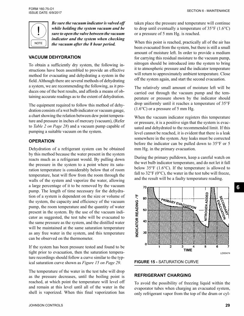
If the system has been pressure tested and found to be tight prior to evacuation, then the saturation tempera-ture recordings should follow a curve similar to the typ-ical saturation curve shown as Figure 15 on Page 29.
The temperature of the water in the test tube will drop as the pressure decreases, until the boiling point is reached, at which point the temperature will level off and remain at this level until all of the water in the shell is vaporized. When this final vaporization has
taken place the pressure and temperature will continue to drop until eventually a temperature of 35°F (1.6°C) or a pressure of 5 mm Hg. is reached.
When this point is reached, practically all of the air has been evacuated from the system, but there is still a small amount of moisture left. In order to provide a medium for carrying this residual moisture to the vacuum pump, nitrogen should be introduced into the system to bring it to atmospheric pressure and the indicator temperature will return to approximately ambient temperature. Close off the system again, and start the second evacuation.
The relatively small amount of moisture left will be carried out through the vacuum pump and the tem-perature or pressure shown by the indicator should drop uniformly until it reaches a temperature of 35°F (1.6°C) or a pressure of 5 mm Hg.
When the vacuum indicator registers this temperature or pressure, it is a positive sign that the system is evac-uated and dehydrated to the recommended limit. If this level cannot be reached, it is evident that there is a leak somewhere in the system. Any leaks must be corrected before the indicator can be pulled down to 35°F or 5 mm Hg. in the primary evacuation.
During the primary pulldown, keep a careful watch on the wet bulb indicator temperature, and do not let it fall below 35°F (1.6°C). If the temperature is allowed to fall to 32°F (0°C), the water in the test tube will freeze, and the result will be a faulty temperature reading.
FIGURE 15 - SATURATION CURVE
LD00474
IND
ICAT
OR
REA
DIN
G -°
F
TIME
PRIMARY EVACUATIONN
ITR
OG
EN A
DD
ED SECONDARY
EVACUATION
REFRIGERANT CHARGINGTo avoid the possibility of freezing liquid within the evaporator tubes when charging an evacuated system, only refrigerant vapor from the top of the drum or cyl-
JOHNSON CONTROLS30
FORM 160.75-O1 ISSUE DATE: 6/9/2017SECTION 6 - MAINTENANCE
inder must be admitted to the system pressure until the system pressure is raised above the point correspond-ing to the freezing point of the evaporator liquid. For water, the pressure corresponding to the freezing point is 8.54 PSIG (58.9 kPa) for R-134a (at sea level).
While charging, every precaution must be taken to pre-vent moisture laden air from entering the system. Make up a suitable charging connection from new copper tub-ing to fit between the system charging valve and the fit-ting on the charging drum. This connection should be as short as possible but long enough to permit sufficient flexibility for changing drums. The charging connection should be purged each time a full container of refrigerant is connected and changing containers should be done as quickly as possible to minimize the loss of refrigerant.
Refrigerant may be furnished in cylinders containing either 30, 50, 125, 1,025 or 1750 lbs. (13.6, 22.6, 56.6, 464 or 794 kg) of refrigerant.
The nameplate on the chiller contains the correct refrigerant charge information for the chiller.
CHECKING THE REFRIGERANT CHARGE DURING UNIT SHUTDOWNThe refrigerant charge is specified for each chiller model. Charge the correct amount of refrigerant and record the level in the evaporator sight glass.
The refrigerant charge should always be checked and trimmed when the system is shut down.
The refrigerant charge level must be checked after the pressure and temperature have equalized between the condenser and evaporator. This would be expected to be 4 hours or more after the compressor and water pumps are stopped. The level should visible in the sight glass.
Charge the refrigerant in accordance with the meth-od shown under the REFRIGERANT CHARGING, above. The refrigerant level should be observed and the level recorded after initial charging.
HANDLING REFRIGERANT FOR DISMANTLING AND REPAIRSIf it becomes necessary to open any part of the refriger-ant system for repairs, it will be necessary to remove the charge before opening any part of the unit. If the chiller is equipped with optional valves, the refrigerant can be isolated in either the condenser or evaporator / compressor while making any necessary repairs.
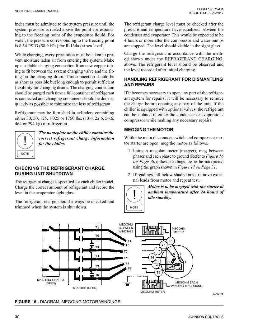
MEGGING THE MOTORWhile the main disconnect switch and compressor mo-tor starter are open, meg the motor as follows:
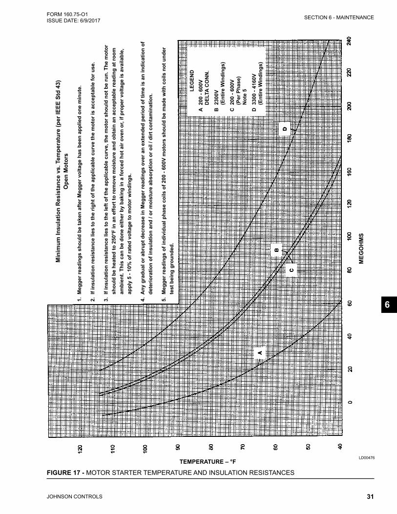
1. Using a megohm meter (megger), meg between phases and each phase to ground (Refer to Figure 16 on Page 30); these readings are to be interpreted using the graph shown in Figure 17 on Page 31.
2. If readings fall below shaded area, remove exter-nal leads from motor and repeat test.
Motor is to be megged with the starter at ambient temperature after 24 hours of idle standby.
FIGURE 16 - DIAGRAM, MEGGING MOTOR WINDINGS
LD00475
MAIN DISCONNECT(OPEN)
STARTER (OPEN)MEGOHM METER
MEGOHM EACHWINDING TO GROUND
MEGOHM METER
MEGOHM BETWEENWINDINGS
JOHNSON CONTROLS 31
SECTION 6 - MAINTENANCEFORM 160.75-O1 ISSUE DATE: 6/9/2017
LD00476
FIGURE 17 - MOTOR STARTER TEMPERATURE AND INSULATION RESISTANCES
TEMPERATURE – °F
MEG
OH
MS
Min
imum
Insu
latio
n R
esis
tanc
e vs
. Tem
pera
ture
(per
IEEE
Std
43)
O
pen
Mot
ors
1. M
egge
r rea
ding
s sh
ould
be
take
n af
ter M
egge
r vol
tage
has
bee
n ap
plie
d on
e m
inut
e.
2. I
f ins
ulat
ion
resi
stan
ce li
es to
the
right
of t
he a
pplic
able
cur
ve th
e m
otor
is a
ccep
tabl
e fo
r use
.
3. I
f ins
ulat
ion
resi
stan
ce li
es to
the
left
of th
e ap
plic
able
cur
ve, t
he m
otor
sho
uld
not b
e ru
n. T
he m
otor
sh
ould
be
heat
ed to
250
°F in
an
effo
rt to
rem
ove
moi
stur
e an
d ob
tain
an
acce
ptab
le re
adin
g at
room
am
bien
t. Th
is c
an b
e do
ne e
ither
by
baki
ng in
a fo
rced
hot
air
oven
or,
if pr
oper
vol
tage
is a
vaila
ble,
ap
ply
5 - 1
0% o
f rat
ed v
olta
ge to
mot
or w
indi
ngs.
4. A
ny g
radu
al o
r abr
upt d
ecre
ase
in M
egge
r rea
ding
s ov
er a
n ex
tend
ed p
erio
d of
tim
e is
an
indi
catio
n of
de
terio
ratio
n of
insu
latio
n an
d / o
r moi
stur
e ab
sorp
tion
or o
il / d
irt c
onta
min
atio
n.
5. M
egge
r rea
ding
s of
indi
vidu
al p
hase
coi
ls o
f 200
- 60
0V m
otor
s sh
ould
be
mad
e w
ith c
oils
not
und
er
test
bei
ng g
roun
ded.
6
LEG
END
A 2
00 -
600V
D
ELTA
CO
NN
.
B 2
300V
(E
ntire
Win
ding
s)
C 2
00 -
600V
(P
er P
hase
) N
ote
5
D 3
300
- 416
0V
(Ent
ire W
indi
ngs)
JOHNSON CONTROLS32
FORM 160.75-O1 ISSUE DATE: 6/9/2017SECTION 6 - MAINTENANCE
Condensers And Evaporators GeneralMaintenance of condenser and evaporator shells is im-portant to provide trouble free operation of the chiller. The water side of the tubes in the shell must be kept clean and free from scale. Proper maintenance such as tube cleaning, and testing for leaks, is covered on the following pages.
Chemical Water TreatmentSince the mineral content of the water circulated through evaporators and condensers varies with almost every source of supply, it is possible that the water be-ing used may corrode the tubes or deposit heat resistant scale in them. Reliable water treatment companies are available in most larger cities to supply a water treat-ing process which will greatly reduce the corrosive and scale forming properties of almost any type of water.
As a preventive measure against scale and corrosion and to prolong the life of evaporator and condenser tubes, a chemical analysis of the water should be made preferably before the system is installed. A reliable wa-ter treatment company can be consulted to determine whether water treatment is necessary, and if so, to fur-nish the proper treatment for the particular water con-dition.
Cleaning Evaporator And Condenser Tubes
EvaporatorIt is difficult to determine by any particular test wheth-er possible lack of performance of the water evaporator is due to fouled tubes alone or due to a combination of troubles. Trouble which may be due to fouled tubes is indicated when, over a period of time, the cooling capacity decreases and the split (temperature differ-ence between water leaving the evaporator and the refrigerant temperature in the evaporator) increases. A gradual drop-off in cooling capacity can also be caused by a gradual leak of refrigerant from the system or by a combination of fouled tubes and shortage of refrigerant charge. An excessive quantity of oil in the evaporator can also contribute to erratic performance.
CondenserIn a condenser, trouble due to fouled tubes is usually indicated by a steady rise in head pressure, over a pe-riod of time, accompanied by a steady rise in condens-ing temperature, and noisy operation. These symptoms may also be due to foul gas buildup. Purging will re-move the foul gas revealing the effect of fouling.
Tube FoulingFouling of the tubes can be due to deposits of two types as follows:
1. Rust or sludge – which finds its way into thetubes and accumulates there. This material usu-ally does not build up on the inner tube surfaces as scale, but does interfere with the heat transfer. Rust or sludge can generally be removed from the tubes by a thorough brushing process.
2. Scale – due to mineral deposits. These deposits, even though very thin and scarcely detectable upon physical inspection, are highly resistant to heat transfer. They can be removed most effec-tively by circulating an acid solution through the tubes.
Tube Cleaning Procedures
Brush Cleaning of TubesIf the tube consists of dirt and sludge, it can usually be removed by means of the brushing process. Drain the water sides of the circuit to be cleaned (cooling wa-ter or chilled water) remove the heads and thorough-ly clean each tube with a soft bristle bronze or nylon brush. DO NOT USE A STEEL BRISTLE BRUSH. A steel brush may damage the tubes.
Improved results can be obtained by admitting water into the tube during the cleaning process. This can be done by mounting the brush on a suitable length of 1/8" pipe with a few small holes at the brush end and con-necting the other end by means of a hose to the water supply.
The tubes should always be brush cleaned before acid cleaning.
Acid Cleaning Of TubesIf the tubes are fouled with a hard scale deposit, they may require acid cleaning. It is important that before acid cleaning, the tubes be cleaned by the brushing process described above. If the relatively loose foreign material is removed before the acid cleaning, the acid solution will have less material to dissolve and flush from the tubes with the result that a more satisfactory cleaning job will be accomplished with a probable sav-ing of time.
JOHNSON CONTROLS 33
SECTION 6 - MAINTENANCEFORM 160.75-O1 ISSUE DATE: 6/9/2017
Acid cleaning should only be performed by an expert. Please consult your local water treatment representative for as-sistance in removing scale buildup and preventative maintenance programs to eliminate future problems. COMMER-CIAL ACID CLEANING
In many major cities, commercial organizations now offer a specialized service of acid cleaning evaporators and condensers. If acid cleaning is required, YORK recommends the use of this type of organization. The Dow Industries Service Division of the Dow Chemical Company, Tulsa, Oklahoma, with branches in principal cities is one of the most reliable of these companies.
Testing For Evaporator And Condenser Tube LeaksEvaporator and condenser tube leaks in R-134a sys-tems may result in refrigerant leaking into the water circuit, or water leaking into the shell depending on the pressure levels. If refrigerant is leaking into the water, it can be detected at the liquid head vents after a period of shutdown. If water is leaking into the refrigerant, system capacity and efficiency will drop off sharply. If a tube is leaking and water has entered the system, the evaporator and condenser should be valved off from the rest of the water circuit and drained immediately to prevent severe rusting and corrosion. The refrigerant system should then be drained and purged with dry ni-trogen to prevent severe rusting and corrosion. If a tube leak is indicated, the exact location of the leak may be determined as follows:
1. Remove the heads and listen at each section of tubes for a hissing sound that would indicate gas leakage. This will assist in locating the section of tubes to be further investigated. If the probable location of the leaky tubes has been determined, treat that section in the following manner (if the locationisnotdefinite,all thetubeswillrequireinvestigations).
2. Wash off both tube heads and the ends of all tubes with water.
Do not use carbon tetrachloride for this purpose since its fumes give the same flame discoloration that the refrigerant does.
3. With nitrogen or dry air, blow out the tubes to clear them of traces of refrigerant laden moisture from the circulation water. As soon as the tubes are clear, a cork should be driven into each end of the tube. Pressurize the dry system with 50 to 100 PSIG (345 to 690 kPa) of nitrogen. Repeat this with all of the other tubes in the suspected section or, if necessary, with all the tubes in the evaporator or condenser. Allow the evaporator or condenser to remain corked up to 12 to 24 hours before proceeding. Depending upon the amount of leakage, the corks may blow from the end of a tube, indicating the location of the leakage. If not, if will be necessary to make a very thorough test with the leak detector.
4. After the tubes have been corked for 12 to 24 hours, it is recommended that two men working at both ends of the evaporator carefully test each tube – one man removing corks at one end and the other at the opposite end to remove corks and handle the leak detector. Start with the top row of tubes in the section being investigated. Remove the corks at the ends of one tube simultaneously and insert the exploring tube for 5 seconds – this should be long enough to draw into the detec-tor any refrigerant gas that might have leaked through the tube walls. A fan placed at the end of the evaporator opposite the detector will assure that any leakage will travel through the tube to the detector.
5. Markanyleakingtubesforlateridentification.
6. If any of the tube sheet joints are leaking, the leak should be indicated by the detector. If a tube sheet leak is suspected, its exact location may be found by using a soap solution. A continuous buildup of bubbles around a tube indicates a tube sheet leak.
COMPRESSORMaintenance for the compressor assembly consists of checking the operation of the oil return system and changing the dehydrator, checking and changing the oil, checking and changing the oil filters, checking the op-eration of the oil heater, checking the operation of the oil pump, and observing the operation of the compressor.
6
JOHNSON CONTROLS34
FORM 160.75-O1 ISSUE DATE: 6/9/2017SECTION 6 - MAINTENANCE
Internal wearing of compressor parts could be a seri-ous problem caused by improper lubrication, brought about by restricted oil lines, passages, or dirty oil fil-ters. If the unit is shutting down on (HOT) High Oil Temperature or Low Oil Pressure (OP), change the oil filter element. Examine the oil filter element for the presence of aluminum particles. Aluminum gas seal rings can contact the impeller and account for some aluminum particles to accumulate in the oil filter, espe-cially during the initial start up and first several months
of operation. However, if aluminum particles continue to accumulate and the same conditions continue to stop the unit operation after a new filter is installed, notify the nearest Johnson Controls office to request the pres-ence of a Johnson Controls Service Technician.
ELECTRICAL CONTROLSFor information covering the OptiView™ Control Cen-ter operation, refer to the Optiview™ Control Center – Operation and Maintenance (Form 160.54-O1).
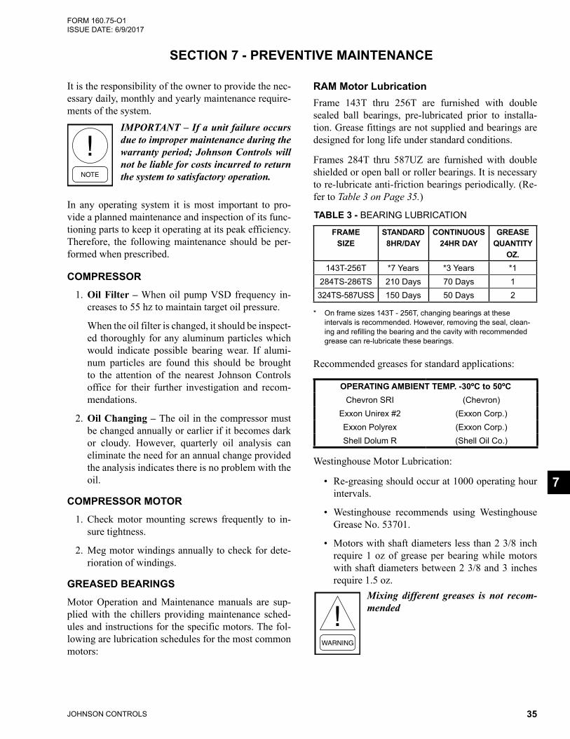
JOHNSON CONTROLS 35
FORM 160.75-O1 ISSUE DATE: 6/9/2017
SECTION 7 - PREVENTIVE MAINTENANCE
It is the responsibility of the owner to provide the nec-essary daily, monthly and yearly maintenance require-ments of the system.
IMPORTANT – If a unit failure occurs due to improper maintenance during the warranty period; Johnson Controls will not be liable for costs incurred to return the system to satisfactory operation.
In any operating system it is most important to pro-vide a planned maintenance and inspection of its func-tioning parts to keep it operating at its peak efficiency. Therefore, the following maintenance should be per-formed when prescribed.
COMPRESSOR1. Oil Filter – When oil pump VSD frequency in-
creases to 55 hz to maintain target oil pressure.
When the oil filter is changed, it should be inspect-ed thoroughly for any aluminum particles which would indicate possible bearing wear. If alumi-num particles are found this should be brought to the attention of the nearest Johnson Controls office for their further investigation and recom-mendations.
2. Oil Changing – The oil in the compressor must be changed annually or earlier if it becomes dark or cloudy. However, quarterly oil analysis can eliminate the need for an annual change provided the analysis indicates there is no problem with the oil.
COMPRESSOR MOTOR1. Check motor mounting screws frequently to in-
sure tightness.
2. Meg motor windings annually to check for dete-rioration of windings.
GREASED BEARINGS Motor Operation and Maintenance manuals are sup-plied with the chillers providing maintenance sched-ules and instructions for the specific motors. The fol-lowing are lubrication schedules for the most common motors:
RAM Motor LubricationFrame 143T thru 256T are furnished with double sealed ball bearings, pre-lubricated prior to installa-tion. Grease fittings are not supplied and bearings are designed for long life under standard conditions.
Frames 284T thru 587UZ are furnished with double shielded or open ball or roller bearings. It is necessary to re-lubricate anti-friction bearings periodically. (Re-fer to Table 3 on Page 35.)
TABLE 3 - BEARING LUBRICATION
FRAME SIZE
STANDARD 8HR/DAY
CONTINUOUS 24HR DAY
GREASE QUANTITY
OZ.143T-256T *7 Years *3 Years *1
284TS-286TS 210 Days 70 Days 1324TS-587USS 150 Days 50 Days 2
* On frame sizes 143T - 256T, changing bearings at these intervals is recommended. However, removing the seal, clean-ing and refilling the bearing and the cavity with recommended grease can re-lubricate these bearings.
Recommended greases for standard applications:
OPERATING AMBIENT TEMP. -30ºC to 50ºCChevron SRI (Chevron)
Exxon Unirex #2 (Exxon Corp.)Exxon Polyrex (Exxon Corp.)Shell Dolum R (Shell Oil Co.)
Westinghouse Motor Lubrication:
• Re-greasing should occur at 1000 operating hour intervals.
• Westinghouse recommends using Westinghouse Grease No. 53701.
• Motors with shaft diameters less than 2 3/8 inch require 1 oz of grease per bearing while motors with shaft diameters between 2 3/8 and 3 inches require 1.5 oz.
Mixing different greases is not recom-mended
7
JOHNSON CONTROLS36
FORM 160.75-O1 ISSUE DATE: 6/9/2017SECTION 7 - PREVENTIVE MAINTENANCE
Additional information on motor lubrica-tion and other service issues can be found in the A-C Motors Instruction Manual.
LEAK TESTINGThe unit should be leak tested monthly. Any leaks found must be repaired immediately.
EVAPORATOR AND CONDENSERThe major portion of maintenance on the condenser and evaporator will deal with the maintaining the wa-ter side of the condenser and evaporator in a clean condition.
The use of untreated water in cooling towers, closed water systems, etc. frequently results in one or more of the following:
1. Scale Formation.
2. Corrosion or Rusting.
3. Slime and Algae Formation.
It is therefore to the benefit of the user to provide for proper water treatment to provide for a longer and more economical life of the equipment. The following recommendation should be followed in determining the condition of the water side of the condenser and evaporator tubes.
1. The condenser tubes should be cleaned annually or earlier if conditions warrant. If the temperature difference between the water off the condenser and the condenser liquid temperature is more than 4°F (2°C) greater than the difference recorded on
a new unit, it is a good indication that the con-denser tubes require cleaning. Refer to SECTION 6 - MAINTENANCE of this manual for condenser tube cleaning instructions.
2. The evaporator tubes under normal circumstances will not require cleaning. If the temperature dif-ference between the refrigerant and the chilled water increases slowly over the operating season, it is an indication that the evaporator tubes may be fouling or that there may be a water bypass in the waterbox requiring gasket replacement or refrig-erant may have leaked from the chiller.
3. Heat recovery condenser tubes should be evalu-ated similiar to evaporator tubes when the heating circuit is a treated, closed loop. Fouling could be detected as ability to meet heat load requirements decreases.
OIL RETURN SYSTEM1. Change the dehydrator in the oil return system
semi-annually or earlier if the oil return system fails to operate.
2. When the dehydrator is changed, the nozzle of the eductor should be checked for any foreign par-ticles that may be obstructing the jet.
ELECTRICAL CONTROLS1. All electrical controls should be inspected for ob-
vious malfunctions.
2. It is important that the factory settings of controls (operation and safety) not be changed. If the set-tings are changed without Johnson Controls ap-proval, the warranty will be jeopardized.
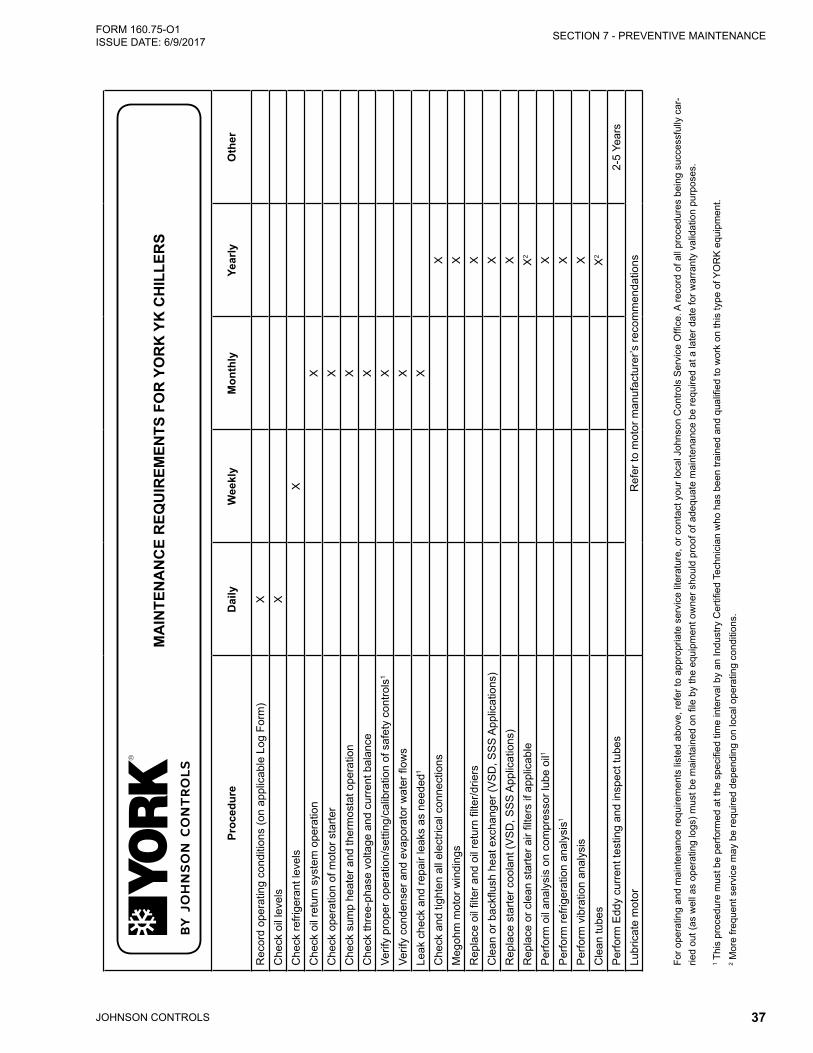
JOHNSON CONTROLS 37
SECTION 7 - PREVENTIVE MAINTENANCEFORM 160.75-O1 ISSUE DATE: 6/9/2017
Proc
edur
eD
aily
Wee
kly
Mon
thly
Year
lyO
ther
Rec
ord
oper
atin
g co
nditi
ons
(on
appl
icab
le L
og F
orm
)X
Che
ck o
il le
vels
XC
heck
refri
gera
nt le
vels
XC
heck
oil
retu
rn s
yste
m o
pera
tion
XC
heck
ope
ratio
n of
mot
or s
tarte
rX
Che
ck s
ump
heat
er a
nd th
erm
osta
t ope
ratio
nX
Che
ck th
ree-
phas
e vo
ltage
and
cur
rent
bal
ance
XVe
rify
prop
er o
pera
tion/
setti
ng/c
alib
ratio
n of
saf
ety
cont
rols
1X
Verif
y co
nden
ser a
nd e
vapo
rato
r wat
er fl
ows
XLe
ak c
heck
and
repa
ir le
aks
as n
eede
d1X
Che
ck a
nd ti
ghte
n al
l ele
ctric
al c
onne
ctio
nsX
Meg
ohm
mot
or w
indi
ngs
XR
epla
ce o
il fil
ter a
nd o
il re
turn
filte
r/drie
rsX
Cle
an o
r bac
kflus
h he
at e
xcha
nger
(VS
D, S
SS
App
licat
ions
)X
Rep
lace
sta
rter c
oola
nt (V
SD
, SS
S A
pplic
atio
ns)
XR
epla
ce o
r cle
an s
tarte
r air
filte
rs if
app
licab
leX
2
Per
form
oil
anal
ysis
on
com
pres
sor l
ube
oil1
XP
erfo
rm re
frige
ratio
n an
alys
is1
XP
erfo
rm v
ibra
tion
anal
ysis
XC
lean
tube
sX
2
Per
form
Edd
y cu
rren
t tes
ting
and
insp
ect t
ubes
2-5
Year
sLu
bric
ate
mot
orR
efer
to m
otor
man
ufac
ture
r’s re
com
men
datio
ns
For o
pera
ting
and
mai
nten
ance
requ
irem
ents
list
ed a
bove
, ref
er to
app
ropr
iate
ser
vice
lite
ratu
re, o
r con
tact
you
r loc
al J
ohns
on C
ontro
ls S
ervi
ce O
ffice
. A re
cord
of a
ll pr
oced
ures
bei
ng s
ucce
ssfu
lly c
ar-
ried
out (
as w
ell a
s op
erat
ing
logs
) mus
t be
mai
ntai
ned
on fi
le b
y th
e eq
uipm
ent o
wne
r sho
uld
proo
f of a
dequ
ate
mai
nten
ance
be
requ
ired
at a
late
r dat
e fo
r war
rant
y va
lidat
ion
purp
oses
.
1 Thi
s pr
oced
ure
mus
t be
perfo
rmed
at t
he s
peci
fied
time
inte
rval
by
an In
dust
ry C
ertifi
ed T
echn
icia
n w
ho h
as b
een
train
ed a
nd q
ualifi
ed to
wor
k on
this
type
of Y
OR
K e
quip
men
t. 2 M
ore
frequ
ent s
ervi
ce m
ay b
e re
quire
d de
pend
ing
on lo
cal o
pera
ting
cond
ition
s.
MA
INTE
NA
NC
E R
EQU
IREM
ENTS
FO
R Y
OR
K Y
K C
HIL
LER
S
160.
54-M
R1
(611
) S
uper
sede
s 16
0.54
-MR
1 (8
01)
Issu
e D
ate:
Jun
e 20
, 201
1
JOHNSON CONTROLS38
FORM 160.75-O1 ISSUE DATE: 6/9/2017
NOTES
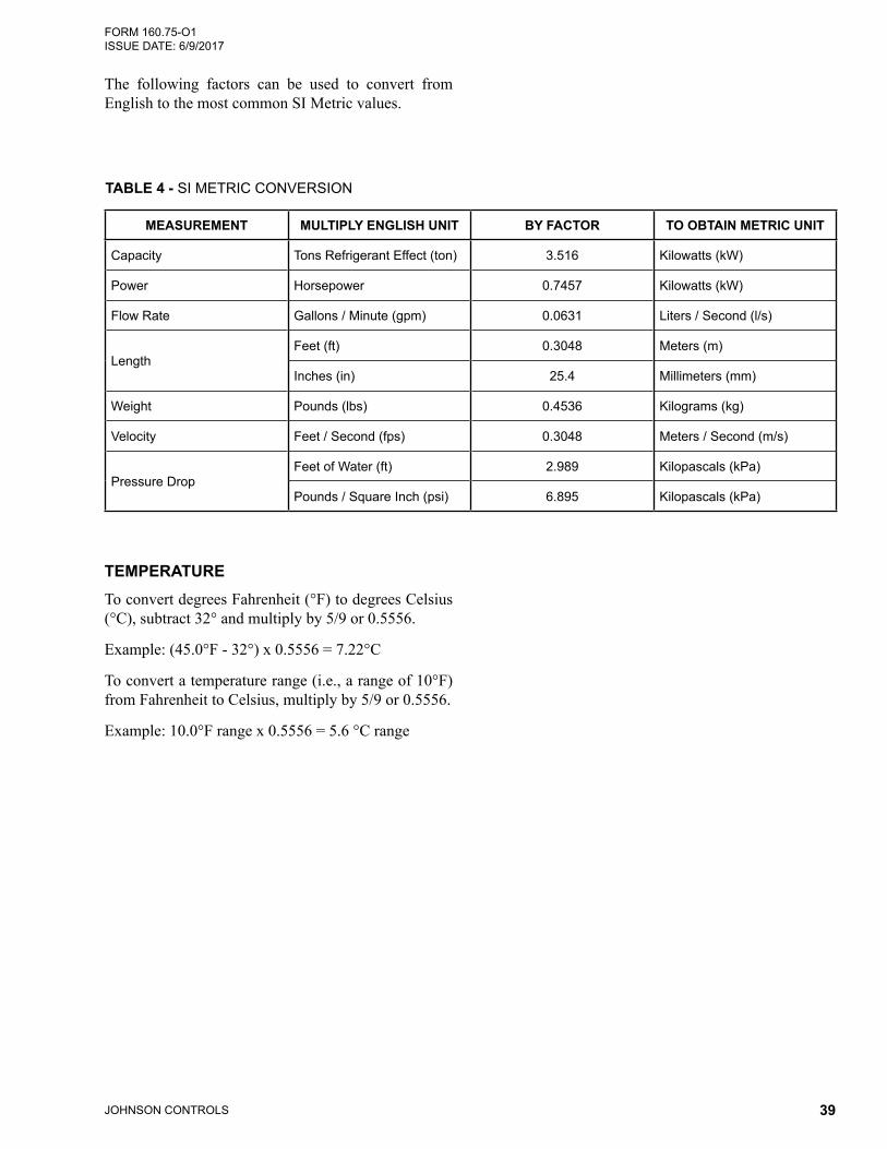
JOHNSON CONTROLS 39
FORM 160.75-O1 ISSUE DATE: 6/9/2017
The following factors can be used to convert from English to the most common SI Metric values.
TEMPERATURETo convert degrees Fahrenheit (°F) to degrees Celsius (°C), subtract 32° and multiply by 5/9 or 0.5556.
Example: (45.0°F - 32°) x 0.5556 = 7.22°C
To convert a temperature range (i.e., a range of 10°F) from Fahrenheit to Celsius, multiply by 5/9 or 0.5556.
Example: 10.0°F range x 0.5556 = 5.6 °C range
TABLE 4 - SI METRIC CONVERSION
MEASUREMENT MULTIPLY ENGLISH UNIT BY FACTOR TO OBTAIN METRIC UNIT
Capacity Tons Refrigerant Effect (ton) 3.516 Kilowatts (kW)
Power Horsepower 0.7457 Kilowatts (kW)
Flow Rate Gallons / Minute (gpm) 0.0631 Liters / Second (l/s)
LengthFeet (ft) 0.3048 Meters (m)
Inches (in) 25.4 Millimeters (mm)
Weight Pounds (lbs) 0.4536 Kilograms (kg)
Velocity Feet / Second (fps) 0.3048 Meters / Second (m/s)
Pressure DropFeet of Water (ft) 2.989 Kilopascals (kPa)
Pounds / Square Inch (psi) 6.895 Kilopascals (kPa)

5000 Renaissance Drive, New Freedom, Pennsylvania USA 17349 800-861-1001 Subject to change without notice. Printed in USACopyright © by Johnson Controls 2011 www.johnsoncontrols.com ALL RIGHTS RESERVEDForm 160.75-O1 (211)Issue Date: February 1, 2011 Supersedes: 160.75-O1 (309)


![Schoolinquir Yk]](https://img.dokumen.tips/doc/110x75/55697c53d8b42a32068b4cd7/schoolinquir-yk.jpg)