Embed Size (px)
Citation preview
Model V-HIP sPecIfIc aPPlIcatIon
attIc sPrInklerVk660
tecHnIcal data
the Viking corporation, 210 n Industrial Park drive, Hastings MI 49058telephone: 269-945-9501 technical services: 877-384-5464 fax: 269-818-1680 email: [email protected]
Visit the Viking website for the latest edition of this technical data page www.vikinggroupinc.com.
Page 1 of 9
Form No. F_092116 17.09.14 Rev 17.2
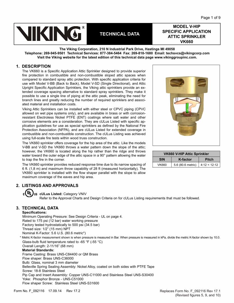
1. descrIPtIonThe VK660 is a Specific Application Attic Sprinkler designed to provide superior fire protection in combustible and non-combustible sloped attic spaces when compared to standard spray attic protection. With specific application criteria for use with Model V-BB (Back to Back), Model V-SD (Single Directional), and Attic Upright Specific Application Sprinklers, the Viking attic sprinklers provide an ex-tended coverage spacing alternative to standard spray sprinklers. They make it possible to use a single line of piping at the attic peak, eliminating the need for branch lines and greatly reducing the number of required sprinklers and associ-ated material and installation costs. Viking Attic Sprinklers can be installed with either steel or CPVC piping (CPVC allowed on wet pipe systems only), and are available in brass or with corrosion-resistant Electroless Nickel PTFE (ENT) coatings where salt water and other corrosive elements are a consideration. They are cULus Listed with specific ap-plication guidelines for use as special sprinklers as defined by the National Fire Protection Association (NFPA), and are cULus Listed for extended coverage in combustible and non-combustible construction. The cULus Listing was achieved using full-scale fire tests within wood truss construction.The VK660 sprinkler offers coverage for the hip area of the attic. Like the models V-BB and V-SD the VK660 throws a water pattern down the slope of the attic; however, the VK660 is located along the hip rather than the ridge and throws water toward the outer edge of the attic space in a 90° pattern allowing the water to trap the fire in the corner. The VK660 sprinkler provides reduced response time due to its narrow spacing of 6 ft. (1,8 m) and maximum throw capability of 28 ft (measured horizontally). The VK660 sprinkler is installed with the flow shaper parallel with the slope to allow maximum coverage of the eaves and hip area.
2. lIstInGs and aPProVals
cUlus listed: Category VNIVRefer to the Approval Charts and Design Criteria on for cULus Listing requirements that must be followed.
3. tecHnIcal dataSpecifications:Minimum Operating Pressure: See Design Criteria - UL on page 4.Rated to 175 psi (12 bar) water working pressureFactory tested hydrostatically to 500 psi (34.5 bar)Thread size: 1/2” (15 mm) NPTNominal K-Factor: 5.6 U.S. (80.6 metric*)
* Metric K-factor measurement shown is when pressure is measured in Bar. When pressure is measured in kPa, divide the metric K-factor shown by 10.0.Glass-bulb fluid temperature rated to -65 °F (-55 °C)Overall Length: 2-11/16” (68 mm)Material standards:Frame Casting: Brass UNS-C84400 or QM BrassFlow shaper: Brass UNS-C36000Bulb: Glass, nominal 3 mm diameterBelleville Spring Sealing Assembly: Nickel Alloy, coated on both sides with PTFE TapeScrew: 18-8 Stainless SteelPip Cap and Insert Assembly: Copper UNS-C11000 and Stainless Steel UNS-S30400Yoke: Phosphor Bronze - UNS-C51000Flow shaper Screw: Stainless Steel UNS-S31600
Replaces Form No. F_092116 Rev 17.1(Revised figures 5, 9, and 10)
Vk660 V-HIP attic sprinklersIn k-factor Pitch
VK660 5.6 (80.6 metric) 4:12 < 12:12

Model V-HIP sPecIfIc aPPlIcatIon
attIc sPrInklerVk660
tecHnIcal data
the Viking corporation, 210 n Industrial Park drive, Hastings MI 49058telephone: 269-945-9501 technical services: 877-384-5464 fax: 269-818-1680 email: [email protected]
Visit the Viking website for the latest edition of this technical data page www.vikinggroupinc.com.
Page 2 of 9
Form No. F_092116 17.09.14 Rev 17.2
figure 1: Installation
ordering Information: (Also refer to the current Viking price list.)Sprinkler base part number: 20952To order the VK660 Attic Sprinkler, add the appropriate suffix for the sprinkler finish and then the appropriate suffix for the
temperature rating to the sprinkler base part number.Finish Suffix: Brass = A, ENT = JNTemperature Suffix: E = 200 °F (93.3 °C)For example, sprinkler VK660 with a Brass finish and 200 °F (93.3 °C) temperature rating = Part No. 20952AEavailable finishes and temperature ratings: Refer to the approval chart on page 3.accessories: (Also refer to the Viking website.)sprinkler Wrench:Standard Wrench: Part No. 10896W/Bsprinkler cabinets:A. Six-head capacity: Part No. 01724AB. Twelve-head capacity: Part No. 01725A
4. InstallatIonThe Model V-HIP Sprinkler must be installed in the upright position with the top of the flow shaper parallel to the slope of the hip ridgeline and the flow direction (indicated by arrows on the top of the flow shaper) pointing down the 2 opposing slopes. Refer to appropriate NFPA Installation Standards.
5. oPeratIonDuring a fire condition, the heat sensitive liquid in the glass bulb expands, causing the glass to shatter, releasing the pip cap and sealing spring assembly. Water flowing through the sprinkler orifice strikes the flow shaper, forming a uniform spray pattern to ex-tinguish or control the fire, and protect the piping in the attic space.
6. InsPectIons, tests and MaIntenanceRefer to NFPA 25 for Inspection, Testing and Maintenance requirements.
7. aVaIlabIlItyViking Sprinkler VK660 is available through a network of domestic and international distributors. See The Viking Corporation web site for the closest distributor or contact The Viking Corporation.
8. GUaranteeFor details of warranty, refer to Viking’s current list price schedule or contact Viking directly.
TOP OF FLOW SHAPER PARALLEL TO HIP RIDGELINE
DO NOT hold the sprinkler using the flow shaper. Use the wrench flats and the standard sprinkler wrench to install.
NOTICE

Model V-HIP sPecIfIc aPPlIcatIon
attIc sPrInklerVk660
tecHnIcal data
the Viking corporation, 210 n Industrial Park drive, Hastings MI 49058telephone: 269-945-9501 technical services: 877-384-5464 fax: 269-818-1680 email: [email protected]
Visit the Viking website for the latest edition of this technical data page www.vikinggroupinc.com.
Page 3 of 9
Form No. F_092116 17.09.14 Rev 17.2
aPProVal cHartViking V-HIP specific application sprinkler
for Combustible and Non-Combustible Sloped Attic Spaces
Part number1 sIn Maximum
Pressurethread size nominal
k-factoroverall length listings and approvals3
nPt bsP U.s. metric2 Inches mm cUlus4 fM lPcb 20952 VK660 175 psi 1/2” 15 mm 5.6 80.6 2-11/16 68 A1, A2 -- -- -- --
approved temperature ratingA - 200 °F (93.3 °C)
approved finish1 - Brass, 2 - ENT5
footnotes1 Also refer to Viking’s current price schedule.2 Metric K-factor measurement shown is when pressure is measured in Bar. When pressure is measured in kPa, divide the metric K-factor shown by 10.0.3 This table shows the listings and approvals available at the time of printing. Other approvals may be in process.4 Listed by Underwriters Laboratories Inc. for use in the United States and Canada.5 cULus Listed as corrosion resistant.
figure 2: sprinkler dimensions
7/16" (11 mm) nominal Pipe engagement
1/2" (15 mm)nPt
2-11/16"(68 mm)
1-3/4"(45 mm)
1-3/8"(35 mm)
table 1: aVaIlable sPrInkler teMPeratUre ratInGs and fInIsHes
sprinkler temperature classification
sprinkler nominal temperature rating1
Maximum ambient ceiling temperature2 bulb color
Intermediate 200 °F (93.3 °C) 150 °F (65°C) Green
sprinkler finishes: Brass, ENT3
footnotes1 The sprinkler temperature rating is stamped on the flow shaper. 2 Based on NFPA-13. Other limits may apply, depending on fire loading, sprinkler location, and other requirements of the Authority Having Jurisdiction.
Refer to specific installation standards.3 cULus Listed as corrosion resistant.

Model V-HIP sPecIfIc aPPlIcatIon
attIc sPrInklerVk660
tecHnIcal data
the Viking corporation, 210 n Industrial Park drive, Hastings MI 49058telephone: 269-945-9501 technical services: 877-384-5464 fax: 269-818-1680 email: [email protected]
Visit the Viking website for the latest edition of this technical data page www.vikinggroupinc.com.
Page 4 of 9
Form No. F_092116 17.09.14 Rev 17.2
desIGn crIterIa - Ul chart 1(Also refer to Approval Chart)
Allowable, flow, pressure and slope for attic protection using Viking VK660 Sprinklers
sprinkler base Part number
sIn typethread size nominal
k-factor allowable roof span2,
4 ft. (m)
Minimum flow
Minimum Pressure
Pitch1
dry Pipe system Maximum Water delivery time3
(in seconds)nPt bsP U.s. metric GPM lPM PsI bar
20952 VK660 HIP 1/2” 15 mm 5.6 80,6 ≤ 20 (6,1) 24 90.8 20 1,4 4:12 < 12:12 See footnote 320952 VK660 HIP 1/2” 15 mm 5.6 80,6 >20 (6,1) to ≤ 28 (8,5) 34 128.7 36.9 2,5 4:12 < 12:12 See footnote 3
footnotes1 Pitch and slope indicate the incline of a roof, expressed as a proportion of the vertical rise to the horizontal run.2 Maximum coverage at eaves can be extended up to 10'-0" (3,05 m) by installing a single row of Attic Upright VK696 or VK697 sprinklers. 3 Refer to NFPA 13, 2013, Section 7.2.3.4 The V-HIP roof span is measured horizontally as shown in Figure 5.
IMPortant: always refer to bulletin form no. f_091699 - care and Handling of sprinklers. also refer to bulletin form no. f_080614 for general care, installation, and maintenance information. Viking sprinklers are to be installed in accordance with the latest edition of Viking technical data, the appropriate standards of nfPa, lPcb, aPsad, Vds or other similar organiza-tions, and also with the provisions of governmental codes, ordinances, and standards, whenever applicable.
addItIonal desIGn crIterIa - Ul chart 2 (also refer to approval chart 1 and design criteria - Ul chart 1)
Allowable , flow, pressure and slope for attic protection using Viking VK660 Sprinklers
design criteria: flow and pressures refer to design criteria - Ul chart 1.system type: Wet systems and dry systems.Piping types: Steel (wet and dry) CPVC (wet systems only).occupancy classification: light hazard only.Viking V-HIP sprinkler spacingMaximum coverage area: The maximum coverage area for the V-HIP sprinkler is the distance down the greater of the 2 slopes, multiplied by 2, then multiplied by the distance between the V-HIP sprinklers on the branchlines, measured along the slope.Minimum distance of V-HIP sprinkler between other sprinklers along branchline: 4'-0" (1,22 m) - From V-BB and V-SD Sprinklers.3'-0" (0,91 m) - From V-HIP Sprinklers.7'-0" (2,13 m) - From Attic Upright Sprinklers.6'-0" (1,83 m) - From Standard Spray Sprinklers.Maximum distance of V-HIP sprinkler between other sprinklers along branchline: 6"-0" (1,83 m) - Center to center from V-BB, V-SD, and V-HIP Sprinklers.10'-0" (3,05 m) - Center to center from Attic Upright Sprinklers.flow shaper position below peak, ridge, or deck:For all roof pitches as per the listing from 4:12 – 12:12 the maximum flow shaper distance down is 22” (560 mm), and the minimumflow shaper distance down is 16” (405 mm).Minimum distance from truss:6” (152 mm) from nearest edge of the truss.Maximum distance from center line of the ridge:6” (152 mm) on either side of the center line.draft curtains:Where used to allow Attic Upright Sprinkler installation shall be constructed to contain heat, may be constructed of minimum ½”(13 mm) plywood or equivalent.
Continues on next page.

Model V-HIP sPecIfIc aPPlIcatIon
attIc sPrInklerVk660
tecHnIcal data
the Viking corporation, 210 n Industrial Park drive, Hastings MI 49058telephone: 269-945-9501 technical services: 877-384-5464 fax: 269-818-1680 email: [email protected]
Visit the Viking website for the latest edition of this technical data page www.vikinggroupinc.com.
Page 5 of 9
Form No. F_092116 17.09.14 Rev 17.2
Continued from previous page.
Use of Ul listed cPVc blazeMaster® piping (wet systems only): Can be used to supply the sprinklers protecting the floor below the combustible concealed space when covered with 6” (152 mm) of non-combustible insulation over the horizontal or vertical piping, and extending 12” (304 mm) on both sides of the center line of the piping. If the piping is located in the joist, the width of the joist channel must be entirely covered to 6” (152 mm) above the top of the piping. The area above the piping must be protected with the Model V-HIP's, V-BB’s, V-SD’s, or the Attic Upright Sprinklers.
Listed CPVC BlazeMaster® piping may also be used exposed to feed wet systems using Viking V-HIP sprinklers in accordance with the following requirements, and in accordance with Figure 6:
• Risers are vertical and protected by V-BB, V-SD, or V-HIP sprinklers located a maximum of 12" (304 mm) away from the riser centerline.• Model V-HIP, V-BB, or V-SD sprinklers are mounted directly to the branchline.• Model V-HIP, V-BB, or V-SD sprinklers are installed on arm-overs a maximum of 6” (152 mm) laterally from the center line of the branch line.• Model V-HIP, V-BB, or V-SD sprinklers are installed on vertical sprigs attached to the branchline.• Model V-HIP, V-BB, or V-SD sprinklers are installed on angled sprigs a maximum of 6” (152 mm) laterally from the centerline of the branchline.• Installed with a minimum lateral distance of 18” (456 mm) from any device that produces and releases heat, i.e. attic furnace, kitchen or bathroom
exhaust fan, flue vents, heat lamps, and other such devices.
Insulation requirements are provided solely for fire protection purposes and not for freeze protection.
Non-combustible insulation needs to be verified for chemical compatibility with the CPVC piping at www.lubrizol.com
Refer to Sections 8.8.5.2.1.3 and 8.8.5.2.1.7 of NFPA 13, 2016 for requirements if installed on greater than 2-1/2” (64 mm) diameter piping.Hydraulic requirements:Viking V-HIP sprinklers must be calculated in accordance with the following figures and guidelines.The design area shall include the most hydraulically demanding sprinklers, and in certain cases may require more than one set ofcalculations to verify the system’s design.The following figures cover hydraulic requirements for Viking V-HIP, V-BB, and V-SD sprinklers, when installed with Attic Upright (or Standard Spray) Sprinklers.refer to figures-unless otherwise noted, all figures portray a 60’ (18,3 m) roof span:Figure 7 – V-BB and V-Hip SprinklersFigure 8 – V-SD and V-Hip SprinklersFigure 9 – V-Hip SprinklersFigure 10 – V-BB, V-Hip, and Attic Upright Sprinklers at the Eaves
V-BB (Back to Back)
Top Side Top Side
V-SD (Single Directional) V-HIP
Top Side Top Side
Attic Upright
figure 3: sprinkler type legend

Model V-HIP sPecIfIc aPPlIcatIon
attIc sPrInklerVk660
tecHnIcal data
the Viking corporation, 210 n Industrial Park drive, Hastings MI 49058telephone: 269-945-9501 technical services: 877-384-5464 fax: 269-818-1680 email: [email protected]
Visit the Viking website for the latest edition of this technical data page www.vikinggroupinc.com.
Page 6 of 9
Form No. F_092116 17.09.14 Rev 17.2
7’-6" (2,3 m) Maximum Horizontal
Maximum span28'-0" (8,5 m)
Horizontal
6'-0" (1,8 m) Maximum3'-0" (0,9 m) Minimum
On the Hip Slope
3'-0" (0,9 m) MaximumOn the Hip Slope
Hip SlopeRoof Slope Max 28'-0" (8
,5 m)
Max 6' (1,8 m)
Out
side
wall
HIP RIDGE
figure 4: design criteria 1
figure 5: design criteria 2
MaIn rIdGe
HIP rIdGea
b
c
d
table 1: desIGn crIterIaref descrIPtIon MInIMUM MaXIMUM
A Flow Shaper to ridge, peak or deck 16" (405 mm) 22" (560 mm)
B Distance from face of truss 6" (152 mm) --
C Distance between sprinklers (as measured
along the slope)3'-0" (0,9 m) 6'-0" (1,8 m)
D Distance to peak (as measured along the
slope)-- 3'-0" (0,9 m)

Model V-HIP sPecIfIc aPPlIcatIon
attIc sPrInklerVk660
tecHnIcal data
the Viking corporation, 210 n Industrial Park drive, Hastings MI 49058telephone: 269-945-9501 technical services: 877-384-5464 fax: 269-818-1680 email: [email protected]
Visit the Viking website for the latest edition of this technical data page www.vikinggroupinc.com.
Page 7 of 9
Form No. F_092116 17.09.14 Rev 17.2
figure 6: exposed cPVc with V-HIP sprinklers
figure 7: V-bb and V-Hip sprinklers
note: dry system shown
note: dry system shown
Wet sytems: Calculate the most demanding 5 sprinklers dry sytems: Calculate the most demanding 7 sprinklers and then calculate the most demanding contiguous 9 sprinklers with a maximum of 7 to be V-BB Sprinklers. Use the most demanding calculation.
Ridge
Ridge
Hip
Hip
Valley
X: 6" (150 mm) Maximumy: 12" (300 mm) Maximum
angle sprig
armover
armover sprig
direct mount
X
X
X
yyyy

Model V-HIP sPecIfIc aPPlIcatIon
attIc sPrInklerVk660
tecHnIcal data
the Viking corporation, 210 n Industrial Park drive, Hastings MI 49058telephone: 269-945-9501 technical services: 877-384-5464 fax: 269-818-1680 email: [email protected]
Visit the Viking website for the latest edition of this technical data page www.vikinggroupinc.com.
Page 8 of 9
Form No. F_092116 17.09.14 Rev 17.2
figure 8: V-sd and V-Hip sprinklers
figure 9: V-Hip sprinklers
Wet sytems: Calculate the most demanding 5 sprinklers dry sytems: Calculate the most demanding 9 sprinklers with a maximum of 7 to be V-SD sprinklers.
Wet sytems: Calculate the most demanding 5 sprinklers. dry sytems: Calculate the most demanding 9 sprinklers.
Ridge
Wall or draft curtain at
ridge
Hip
Hip
Hip
Hip
Hip
note: dry system shown
note: Wet system shown

Model V-HIP sPecIfIc aPPlIcatIon
attIc sPrInklerVk660
tecHnIcal data
the Viking corporation, 210 n Industrial Park drive, Hastings MI 49058telephone: 269-945-9501 technical services: 877-384-5464 fax: 269-818-1680 email: [email protected]
Visit the Viking website for the latest edition of this technical data page www.vikinggroupinc.com.
Page 9 of 9
Form No. F_092116 17.09.14 Rev 17.2
Where the total number of attic Upright sprinklers at the hip is 4 or less:Wet systems - Calculate the most demanding 5 V-BB, V-SD, or V-Hip sprinklers plus up to 2 most demanding Attic Upright sprinklersdry systems - Calculate the most demanding 9 V-BB, V-SD, or V-Hip sprinklers plus up to 2 most demanding Attic Upright sprinklers (Out of the 9, calculate a maximum of 7 V-BB sprinklers).
Ridge
Hip
Wall or draft curtain at
ridge
Reg
ion
2 w
ith A
ttic
Upr
ight
or
V-H
IP S
prin
kler
s
Region 1 with V-BB, V-HIP, or Attic Upright Sprinklers
60'(18,3 m)
6' (1,8 m)
10' (3m)
10' (3m)
10' (3m)
6' (1,8 m)
80'(18,4 m)
Where the total number of attic Upright sprinklers at the hip is greater than 4:Wet systems - Calculate up to the most demanding 5 V-BB, or V-Hip sprinklers plus up to 2 most demanding Attic Upright sprinklers, then calculate the most demanding region up to 1500 ft2 (137 m2) containing Attic Upright sprinklers (Region 2 below). Use the most demanding calculation.dry systems - Calculate up to the most demanding 9 V-BB, or V-Hip sprinklers then add the 2 most demanding Attic Upright sprinklers, then calculate the most demanding region up to 1950 ft2 (181 m2) containing Attic Upright sprinklers. Use the most demanding calculation.
figure 10: V-bb, V-Hip, and attic Upright sprinklers at the eaves
note: dry system shown
note: dry system shown
Replaces Form No. F_092116 Rev 17.1(Revised figures 5, 9, and 10)