Embed Size (px)
Citation preview

INSTALLATION AND OPERATING INSTRUCTIONS
REGENERATIVE DRIVEMODEL KBMG-212D
KB Part No. 8831
Variable Speed SCR Control Designed for Shunt Wound and PM DC Motors
FULL WAVE • 4 QUADRANT
See Safety Warningon Page 3
The information contained in this manual isintended to be accurate. However, themanufacturer retains the right to make changes indesign which may not be included herein.
A COMPLETE LINE OF MOTOR DRIVES
© 1999 KB Electronics, Inc.
TABLE OF CONTENTS
Section Pagei. Simplified Setup and
Operating Instructions . . . . . . . . . . . . . . 1ii. Safety Warning . . . . . . . . . . . . . . . . . . . 3I. General Information . . . . . . . . . . . . . . . . 4II. Operation . . . . . . . . . . . . . . . . . . . . . . . . 5III. Setting Selectable Jumpers . . . . . . . . . . 8IV. Mounting . . . . . . . . . . . . . . . . . . . . . . . 15V. Wiring . . . . . . . . . . . . . . . . . . . . . . . . . 15VI. Fusing . . . . . . . . . . . . . . . . . . . . . . . . . 24VII. Trimpot Adjustments . . . . . . . . . . . . . . 25VIII. Function Indicator Lamps . . . . . . . . . . . 30IX. KBMG-212D Accessories . . . . . . . . . . 30X. Limited Warranty . . . . . . . . . . . . . . . . . 34
TABLES1. Electrical Ratings . . . . . . . . . . . . . . . . . . 52. Summary of Control Operation . . . . . . . 63. General Performance Specifications . 7,84. Jumper J2 Position vs
Motor Horsepower . . . . . . . . . . . . . . . . . 95. Relationship of AC Line Input and Motor
Voltage with J1A, J1B and J3 . . . . . . . 106. Terminal Block Wiring Information . . . . 157. Field Connections . . . . . . . . . . . . . . . . 188. Armature Fuse Chart . . . . . . . . . . . . . . 25
FIGURES Page1. AC Line Voltage Jumper Setting . . . . . . . 102. Motor Armature Voltage
Jumper Setting . . . . . . . . . . . . . . . . . . . . 103. Jumper J4 Setting . . . . . . . . . . . . . . . . . . 114. Jumper J5 Setting . . . . . . . . . . . . . . . . . . 115. Jumper J6 Setting . . . . . . . . . . . . . . . . . . 126. Speed Control Mode . . . . . . . . . . . . . . . . 137. Torque Control Mode . . . . . . . . . . . . . . . 148. AC Line Connection . . . . . . . . . . . . . . . . 169. Armature Connection . . . . . . . . . . . . . . . 1610A. Full Voltage Field . . . . . . . . . . . . . . . . . . 1710B. Half Voltage Field . . . . . . . . . . . . . . . . . . 1711. Main Speed Potentiometer
Connections . . . . . . . . . . . . . . . . . . . . . . 1912. Control Layout . . . . . . . . . . . . . . . . . . . . 2013. Mechanical Specifications . . . . . . . . . . . 2114. Voltage Following Connection . . . . . . . . 2215. Regenerate to Stop . . . . . . . . . . . . . . . . . 2316. Coast to Stop . . . . . . . . . . . . . . . . . . . . . 2317. Tach-Generator Feedback . . . . . . . . . . . 2418. Accel Trimpot Adjustment . . . . . . . . . . . . 2619. Dead Band Trimpot Adjustment . . . . . . . 27
ii
™

i. KBMG-212D SIMPLIFIED OPERATING INSTRUCTIONS
IMPORTANT – You must read these simplified operating instructions before you proceed.These instructions are to be used as a reference only and are not intended to replace thedetailed instructions provided herein. You must read the Safety Warning before proceeding.
1. CONNECTIONS.A. AC Line – Wire AC line voltage to terminals L1 and L2. Be sure jumpers J1A and
J1B are both set to the correct input line voltage 115 or 230 VAC. Connect groundwire (earth) to green ground screw.
B. Motor.
1. Permanent Magnet (PM Type). Connect motor armature leads to M1(+) and M2 (–). Be sure jumper J3 is set to the proper position “A90" for 90 volt DCmotors and “A180" for 180 volt DC motors. Note: 180 volt DC motors must beused with 230 VAC line, 90 volt motors can be used with a 230 VAC or 115 VACline.
Note: Motor performance and efficiency, including brush life, can beadversely affected when using 90 volt motors with a 230 VAC line. Contactmotor manufacturer for derating information.
2. Shunt Wound Motors. Connect motor armature leads as above. Connect fullvoltage shunt field leads (90 volt motors with 100 volt fields and 180 volt with200 volt fields) to F+ and F-. Connect half voltage field leads (90 volt motorswith 50 volt fields and 180 volt motors with 100 volt fields) to F+ and L1.
1
2. MOTOR CURRENT.Jumper J2 is factory set for 7.5 amp motors (7.5A). For lower amperage motors, placeJ2 in the proper position. If motor amperage is less than 1.7 amps, use the 1.7 ampposition and readjust the IR and CL trimpots according to section VII, C and D on pages28 and 29. Note: The factory setting for Current Limit is 150% of the nominal currentsetting (e.g., if J2 is selected for 5 amps, the actual CL setting will be 7.5 amps). Note:If the 10.0 amp setting (10.0A) is required, an auxiliary heatsink (KB P/N 9861) must beused.
3. TRIMPOT SETTINGS.All trimpots have been factory set in accordance with figure 12, p. 20.
4. ENABLE.A jumper must be connected between “EN” and “COM” terminals or control will notoperate. (See sec. V, G, page 22.)
Note: For the location of jumpers and trimpots, see fig. 12, control layout, on page 20.
5. SPEED OR TORQUE MODE.Jumper J5 is factory set for speed control operation (SPD). For torque control, set J5to the “TRQ” position.
2

ii. SAFETY WARNING! — PLEASE READ CAREFULLY
This product should be installed and serviced by a qualified technician, electricianor electrical maintenance person familiar with its operation and the hazards involved.Proper installation, which includes wiring, mounting in proper enclosure, fusing or otherovercurrent protection and grounding, can reduce the chance of electric shocks, fires orexplosion in this product or products used with this product, such as electric motors,switches, coils, solenoids or relays. Eye protection must be worn and insulatedadjustment tools must be used when working with control under power. This product isconstructed of materials (plastics, metals, carbon, silicon, etc.) which may be a potentialhazard. Proper shielding, grounding and filtering of this product can reduce the emissionof radio frequency interference (RFI) which may adversely affect sensitive electronicequipment. If information is required on this product, contact our factory. It is theresponsibility of the equipment manufacturer and individual installer to supply this safetywarning to the ultimate user of this product. (SW effective 11/92)
This control contains electronic Start/Stop and enable circuits that can be used tostart and stop the control. However, these circuits are never to be used as safetydisconnects since they are not fail-safe. Use only the AC line for this purpose.
The input circuits of this control (potentiometer, start/stop, enable) are not isolatedfrom AC line. Be sure to follow all instructions carefully. Fire and/or electrocutioncan result due to improper use of this product.
3
This product complies with all CE directives pertinent at the time ofmanufacture. Contact factory for detailed installation instructions and
Declaration of Conformity. Installation of a CE approved RFI filter (KBRF-200A,KB P/N 9945C or equivalent) is required. Additional shielded motor cable and/orAC line cables may be required along with a signal isolator (model SIMG, KB P/N8832 or equivalent).
I. GENERAL INFORMATION.The KBMG-212D is a full-wave regenerative control, capable of operating a DC motor(Permanent Magnet or Shunt) in a bidirectional mode. It provides 4-quadrant operationwhich allows forward and reverse torque in both speed directions. The drive offersexcellent controllability, which closely approximates the performance of servo-typedrives. Ratings and specifications are presented in tables 1 and 3. Be sure the driveis used within these ratings and specifications.
(Note: Regenerative drives normally produce more motor heating than standardunidirectional SCR speed controls, especially under low speed operation. Thisshould be taken into consideration when specifying motor rating.)
WARNING! Be sure to follow all instructions carefully. Fire orelectrocution can result due to improper use of this product. Read
Safety Warning.
4

TABLE 1 – ELECTRICAL RATINGS
Model No.KB
Part No.
AC LineVoltage
(VAC) ± 10%50/60 Hz
MotorVoltage(VDC)
Rating Without Auxiliary Heatsink
Max. ACLoad Current(RMS Amps)
Max. DCLoad Current(Avg. Amps)
MaximumHorsepower
HP, (KW)
KBMG-212D 8831115 0 – ± 90 12.0 8.0 0.75, (0.5)
230 0 – ± 180 12.0 8.0 1.5, (1.0)
Model No.KB
Part No.
AC LineVoltage
(VAC) ± 10%50/60 Hz
MotorVoltage(VDC)
Rating With Auxiliary Heatsink (KB P/N 9861)
Max. ACLoad Current(RMS Amps)
Max. DCLoad Current(Avg. Amps)
MaximumHorsepower
HP, (KW)
KBMG-212D 8831115 0 – ± 90 16.0 11.0 1, (0.75)
230 0 – ± 180 16.0 11.0 2, (1.5)
II. OPERATION.The KBMG-212D will vary motor speed or torque as a function of the signal voltage oninput terminals “SIG" (signal) and “COM” (common). The input voltage can be derivedfrom the wiper of the main speed potentiometer or from an isolated analog input (signalvoltage following mode). Since the KBMG-212D is a 4-quadrant regenerative drive, themotor speed will follow both a positive and negative signal voltage and drive the motorin both the forward direction and reverse direction. In addition, it will apply both forwardand reverse torque in order to stabilize motor speed.
5
To understand the concept of a regenerative drive, the operation of an elevator can beused. If one were to enter the elevator on the first floor and press 10, the motor andcontrol would have to lift the elevator against gravity. In this mode, the drive wouldoperate like a conventional speed control which is called “motoring” (the applied loadis opposite to the direction of motor rotation). When the elevator is at floor 10 and floor1 is pressed, gravity will try to pull the elevator car down faster than the speed for whichit is set. The control will then provide reverse torque to keep the car from falling fasterthan the set speed. This operation is regeneration (the applied load is in the samedirection as the direction of motor rotation).
The table below summarizes the different modes of operation.
TABLE 2 – SUMMARY OF CONTROL OPERATION
Quadrant Type of OperationMotor Rotation
DirectionMotor Torque
DirectionApplied Load
Direction
I Motoring CW CW CCW
II Regeneration CCW CW CCW
III Motoring CCW CCW CW
IV Regeneration CW CCW CW
6

TABLE 3 – GENERAL PERFORMANCE SPECIFICATIONS
Parameter SpecificationFactorySetting
AC Line Input Voltage (VAC ±10% 50/60 Hz)
AC Line Frequency (Hz)
Armature Voltage Range 115VAC Line (VDC)
Armature Voltage Range 230VAC Line (VDC)
Field Voltage at 115VAC Line (VDC)
Field Voltage at 230VAC Line (VDC)
Max Load Capacity (% for 2 Minutes)
Ambient Temperature Operating Range ( ºC)
Speed Range (Ratio)
Armature Feedback Load Regulation (% Base Speed)
Tach-generator Feedback Load Regulation (% Set Speed)
AC Line Regulation (% Base Speed)
Current Ranges (Amps DC)
Forward Accel (FACC) and Reverse Accel (RACC) Range (Sec.)
Dead Band Range (% Base Speed)
Max Speed Trimpot Range (% Base Speed)
IR Comp Range at 115VAC Line (VDC @ Full Load)
IR Comp Range at 230VAC Line (VDC @ Full Load)
115 or 230
50/60
0 – ± 90
0 – ± 90, 0 – ± 180
100/50
200/100
150
0 – 50
50:1
±1
±1
±0.5
1.7, 2.5, 5.0, 7.5, 10*
0.1 – 15
0 – ±5
55 – 110
0 – 20
0 – 40
230
—
—
0 – ± 180
—
—
—
—
—
—
—
—
7.5
1
1
100
5
10
Continued next page
7
TABLE 3 – GENERAL PERFORMANCE SPECIFICATIONS (Continued)
Parameter SpecificationFactorySetting
Forward CL (FCL) and Reverse CL (RCL) Range (% Range Setting)
Voltage Following Input Range (VDC)**
Voltage Following Linearity (% Base Speed)
0 – 175
0 – ±10, 0 – ±15
±0.5
150
0 – ±15
—
* Requires Auxiliary Heatsink KB P/N 9861.** Requires isolated input or signal isolator.
III. SETTING SELECTABLE JUMPERS.The KBMG-212D has customer selectable jumpers which must be set before the controlcan be used (refer to fig. 1, p. 10). Bold indicates factory setting. See fig. 12, p. 20 forlocation of jumpers.
A. J1A, J1B – Input AC Line Voltage – Select proper input line voltage, 115VAC or230VAC, by placing both J1A and J1B in the correct corresponding position, “115"or “230.” (See fig. 1, p. 10.)
B. J2 – Armature Current – Select the J2 position (1.7, 2.5, 5.0, 7.5, 10) closest tothe rated motor current. (Note: The maximum output current is set to 150% of theJ2 position, which may be readjusted using the FWD CL and REV CL trimpots.)
8

TABLE 4 – JUMPER J2 POSITION vs MOTOR HORSEPOWER
Jumper J2 PositionMotor Current
(DC Amps)
Motor Horsepower HP, (KW)
90VDC 180VDC
10.0A* 1.0, (0.75) 2.0, (1.5)
7.5A 3/4, (0.5) 1, (1.0)
5.0A 1/2, (0.37) 1.0, (0.75)
2.5A 1/4, (0.18) 1/2, (0.37)
1.7A 1/6, (0.12) 1/3, (0.25)
* 10.0A setting requires auxiliary heatsink KB P/N 9861
C. J3 – Motor Armature Voltage – Select the desired armature voltage by placing J4in the proper position, “A90" or “A180.” Note: For 115 volt AC line input, J3must be set to “A90.” For 230 input, the armature voltage is normally set for“A180.” However, it is also possible to set the armature voltage to “A90" for step-down operation. (See fig. 2 and table 5 on page 10.)
J3 – Tach-Generator Feedback (for use with 1800 RPM motors.) – Jumper J3is also used if tach-generator feedback is to be used. (See fig. 2, p. 10) If a 7 voltper 1000 RPM tach-generator is used, set jumper J4 in the “T7" position. For a 50volt per 1000 RPM tach-generator, set the jumper in the “T50" position. Note:When using tach-generator feedback, the IR Comp trimpot should be turned to aminimum setting (full CCW).
9
FIG. 1 – AC LINE VOLTAGEJUMPER SETTING (J1A, J1B)
115VAC 230VAC
FIG. 2 – MOTOR ARMATURE VOLTAGEJUMPER SETTING (J3)
90VDC 180VDC
TABLE 5 – RELATIONSHIP of AC LINE INPUT AND MOTORVOLTAGE with J1A, J1B and J3 JUMPER POSITION
AC LINE INPUT VOLTAGE J1A, J1B POSITION J3 POSITION MOTOR VOLTAGE
115 115 90 90
230 230 180 180
230 230 90* 90*
*A 90VDC motor can be used with a 230VAC line (J3 set in “A90" position). However, speed range maybe reduced and motor derating may be required.
10

FIG. 3 – JUMPER J4 SETTING
Potentiometer Operation Signal Following
FIG. 4 – JUMPER J5 SETTING
Speed Mode Torque Mode
FIG. 5 – JUMPER J6 SETTING
Coast to Stop Regenerate to Stop
D. J4 – Analog Input Voltage –Jumper J4 is set to the “15V”position for potentiometeroperation. If the control is tobe operated from an isolated0 – ±10VDC signal (see sec. V,F, p. 22.), set J4 to the “10V”position.
E. J5 – Control Mode (Speed orTorque).
i. Speed (SPD) Mode – (Note:Factory setting of J5 isSpeed mode.) In the speedcontrol mode (J5 set toSPD), the KBMG-212D willprovide variable speedcontrol. The motor speedwill be in direct proportion tothe input signal. Both forward and reverse torque are used to stabilize motorspeed. (See fig. 6, p. 13.)
ii. Torque (TRQ) Mode – In the torque control mode (J5 set to TRQ), theKBMG-212D will vary the maximum motor torque as a function of the voltageinput to terminals “SIG” (signal) and “COM” (common). This voltage can bederived from the wiper of the main potentiometer or from an isolated analoginput (signal voltage following).
11
If the motor torque is greater than the load torque, the motor will rotate. If noload is applied to the motor, the motor will rotate at a speed proportional to thetorque setting as set by the main potentiometer (see fig. 7, p. 14). By using theACCEL and DECEL trimpots, the application of torque can be made moregradual or less gradual as required by the application. A maximum torque canbe established using the current selector jumper, J2, which can be furthermodified by using the FWD and REV CL trimpots.
F. J6 – Coast to Stop (CTS),Regenerate to Stop (RTS) –This function operates inconjunction with the Enablecircuit, which is used to startand stop the controlelectronically. If the circuitconnecting terminals “EN” and“COM” on terminal block TB1are opened, the control will cause the motor to stop. When jumper J6 is in thefactory position (RTS), the motor will regenerate to a stop.
If J6 is changed to the coast to stop (CTS) position, the motor will coast to a stopwhen the “EN” - “COM” circuit is opened.
Note: Control will not run unless a jumper or closed contact is connectedbetween the “EN” and “COM” terminals.
12

FIG. 6 – SPEED CONTROL MODE
13
FIG. 7 – TORQUE CONTROL MODE (Linear)
14

FIG. 8 – AC LINE CONNECTION
FIG. 9 – ARMATURE CONNECTION
IV. MOUNTING.Mount the KBMG-212D on a flat surface in an atmosphere free of moisture, metal chips,and corrosion. See Mechanical Specifications, fig. 13, p. 21. A 5K ohm remote speedpotentiometer is provided with each control. Install potentiometer using hardwareprovided. Be sure to install insulating disk between potentiometer and inside of frontpanel.
Enclosure – When mounting the KBMG-212D in an enclosure, it must be large enoughto allow the proper heat dissipation. A 12"12"12" enclosure is suitable when thecontrol is not mounted on an auxiliary heatsink. A 12"12"24" enclosure isappropriate at full rating (11.0 amps) when the control is mounted on an auxiliaryheatsink KB P/N 9861.
V. WIRING. Warning! Read Safety Warning before attempting to use this
control.
Warning! To avoid erratic operation do not bundle AC line and motor wires withpotentiometer, voltage following, enable, inhibit or other signal wiring. Useshielded cables on all signal wiring over 12" (30 cm) – Do not ground shield.
TABLE 6 – TERMINAL BLOCK WIRING INFORMATION
Terminal BlockDesignation
ConnectionDesignation
Supply Wire Gauge MaximumTightening
Torque (in-lbs)Minimum Maximum
TB1 Logic Conections 22 14 3.5
15
Wire control in accordance with National ElectricalCode requirements and other local codes thatapply. A “normal blo” 20 amp fuse or circuitbreaker should be used on each AC line conductorthat is not at ground potential (do not fuse neutral orgrounded conductors). (See section VI, p. 24 forfuse information.) Wire control in accordance withconnection diagrams (see figures 8, 9, 10A, 10B, 11and 14 on pages 16, 17, 19 and 22). A separate AC lineswitch or contactor must be wired as a disconnect switch sothat contacts open each ungrounded conductor of the control.See table 6 for terminal block wiring information.
A. AC Line – Connect AC Line toterminals L1 and L2. (Be surejumpers J1A and J1B are set tomatch the AC line voltage used.)(See table 5, p. 10.)
B. Ground – Be sure to ground (earth)control via green screw locatedon chassis.
Do not ground any other terminals.
C. Motor Armature – Connect motor armature to terminals M1 (+) and M2 (–). (Besure jumper J3 is set to match motor voltage.) (See table 5, p. 10.)
16
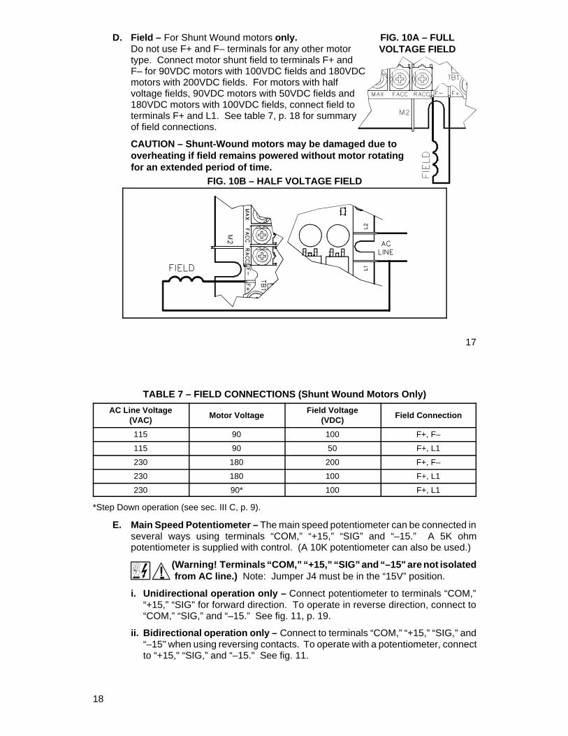
FIG. 10A – FULLVOLTAGE FIELD
D. Field – For Shunt Wound motors only.Do not use F+ and F– terminals for any other motortype. Connect motor shunt field to terminals F+ andF– for 90VDC motors with 100VDC fields and 180VDCmotors with 200VDC fields. For motors with halfvoltage fields, 90VDC motors with 50VDC fields and180VDC motors with 100VDC fields, connect field toterminals F+ and L1. See table 7, p. 18 for summaryof field connections.
CAUTION – Shunt-Wound motors may be damaged due tooverheating if field remains powered without motor rotatingfor an extended period of time.
FIG. 10B – HALF VOLTAGE FIELD
17
TABLE 7 – FIELD CONNECTIONS (Shunt Wound Motors Only)
AC Line Voltage(VAC)
Motor VoltageField Voltage
(VDC)Field Connection
115 90 100 F+, F–
115 90 50 F+, L1
230 180 200 F+, F–
230 180 100 F+, L1
230 90* 100 F+, L1
*Step Down operation (see sec. III C, p. 9).
E. Main Speed Potentiometer – The main speed potentiometer can be connected inseveral ways using terminals “COM,” “+15,” “SIG” and “–15.” A 5K ohmpotentiometer is supplied with control. (A 10K potentiometer can also be used.)
(Warning! Terminals “COM,” “+15,” “SIG” and “–15" are not isolated from AC line.) Note: Jumper J4 must be in the “15V” position.
i. Unidirectional operation only – Connect potentiometer to terminals “COM,”“+15,” “SIG" for forward direction. To operate in reverse direction, connect to“COM,” “SIG,” and “–15.” See fig. 11, p. 19.
ii. Bidirectional operation only – Connect to terminals “COM,” “+15,” “SIG,” and“–15" when using reversing contacts. To operate with a potentiometer, connectto “+15," “SIG,” and “–15." See fig. 11.
18

*Note: A jumper must be wired to EN andCOM in order for control to operate.
Notch denotesposition.
TRIMPOT
FIG. 11 – MAIN SPEED POTENTIOMETER CONNECTIONS
A) Forward B) Reverse
C) Bidirectional with Reversing Contact D) Bidirectional with Speed Pot
19
FIG. 12 – CONTROL LAYOUT(Illustrates Factory Setting of Jumpers and Approximate Trimpot Settings)
20

FIG. 14 – VOLTAGEFOLLOWING CONNECTION
FIG. 13 – MECHANICAL SPECIFICATIONS (INCHES / [mm])
21
F. Voltage Following – An isolated analog voltage can be used in lieuof main speed potentiometer.Connect signal to terminals “SIG"and “COM.” Note: Terminal “COM"is common. A positive signal toterminal “SIG” will produce apositive output to motor.A negative signal to terminal“SIG" will produce a negativeoutput. A 0 to ±10VDC is requiredto operate control from 0 ± fulloutput. Note: Jumper J4 must bein the “10V” position. Note: An isolated signal voltage must be used orcatastrophic failure can result. (A bipolar signal isolator, model SIMG [KB P/N8832], is available as an option from your distributor.)
G. Enable Start/Stop Circuits – The KBMG-212D contains a 2-wire stop circuit(Enable), which is used to electronically bring the motor to a “stop.” An isolatedsingle contact closure is required. If an isolated contact is not available, it may benecessary to use an isolation relay.
*Note: If 2-wire start/stop circuit is not used, a jumper must be wired to ENand COM or control will not operate.
WARNING! Do not use Start/Stop or Enable functions as a safetydisconnect. Use only an AC line disconnect for that purpose.
22

FIG. 17 – TACH-GENERATOR FEEDBACK
i. Regen to a stop using terminals EN and COM on terminal block TB1 –When a contact is opened between terminals “EN” and “COM,” with jumper J6in the “RTS” position, the motor will regeneratively brake to a rapid stop.Application note (See fig. 15): If controlled regen to stop is required, a contactcan be installed in series with the signal “SIG” connection. The braking time willbe equal to the REV ACCEL setting when the motor is in the forward direction,and equal to the FWD ACCEL setting when the motor is in the reverse direction.Note: J4 must be in the “15V” position. (See fig. 11D, p. 19.)
ii. Coast to a stop using terminals “EN” and “COM” on terminal block TB1 –If coast to stop operation is required, move jumper J6 to the coast to stop (CTS)position. When the contact is opened between “EN” and “COM,” the motor willcoast to a stop. See fig. 16.
ENABLE
OPEN TO REGENERATE TO STOP
FIG. 15 – REGENERATE TO STOP
ENABLE
OPEN TO COAST TO STOP
FIG. 16 – COAST TO STOP
*FWD Accel and REV Accel do not affect the stopping time when the enable circuit is opened.
23
H. Tach-generator Feedback – The KBMG-212D is factory set for armature feedback,which provides good load regulation for mostapplications. For superior load regulation,analog tach-generator feedback can beused.
Wire the tach-generator so that the polarity ofthe tach-generator is the same with respectto the input signal polarity (see fig. 17).Note: If tach-generator is wired with reversepolarity, the motor will run at full speed.Note: Jumper J3 must be set to the properposition for tach feedback. See sec III, C, p. 9 and fig. 2 on page 10. Note: Checktach voltage polarity with respect to input signal if polarity does not match reversetach leads.
Be sure AC line is disconnected when rewiring tach-generator.
VI. FUSING.Armature Fuse – It is recommended that the correct size armature fuse be installed,depending on the rating of the motor and form factor (RMS/AVG current). Fuse typeshould be Littelfuse 326 ceramic or Buss ABC, or equivalent. A fuse chart is presentedbelow which suggests appropriate armature fuse ratings. However, the specificapplication may require larger fuse ratings based on ambient temperature, CL set pointand duty cycle of operation (see table 8, p. 25). Fuses may be purchased from yourdistributor. Wire fuse in series with armature lead.
24

SECONDS
7.5
14.01.0
ACCEL TRIMPOT SETTING
0.1 15.0
FIG. 18 – ACCEL TRIMPOT ADJUSTMENT
TABLE 8 – ARMATURE FUSE CHART
Motor Horsepower Approx. DCMotor
Current Amps
Fuse Rating(AC Amps)90VDC 180VDC
1/8 1/4 1.3 2
1/6 1/3 1.7 2
1/4 1/2 2.5 4
1/3 3/4 3.3 5
1/2 1 5.0 8
3/4 1 7.5 12
1 2 10.0 20
VII. TRIMPOT ADJUSTMENTS.The KBMG-212D contains trimpots that have been factory adjusted for mostapplications. See specifications for factory settings. (Note: Fig. 12, p. 20, presents thevarious trimpots with their location. They are shown in the approximate factoryposition.) Some applications may require readjustment of trimpots in order to tailorcontrol to exact requirements. Readjust trimpots as follows:
25
A. Forward Acceleration(FWD ACCEL) andReverse Acceleration(REV ACCEL) – The FWDACCEL trimpot determinesthe amount of time it takesthe control voltage to reachfull output in the forwarddirection. It also determinesthe amount of time it takesfor the control voltage, in thereverse direction, to reachzero output. (FWD ACCELis the Reverse Decel.)
The REV ACCEL trimpotdetermines the amount oftime it takes the controlvoltage to reach full output in the reverse direction and the time it takes for thecontrol voltage, in the forward direction, to reach zero output. (REV ACCEL is theForward Decel.)
The FWD and REV ACCEL trimpots are factory adjusted to approximately 1second. The acceleration times are adjustable over a range of 0.1 to 15 seconds.See fig. 18 for graphical representation of ACCEL.
Note: The FWD and REV CL trimpots may override the rapid accel and decelsettings.
26

FIG. 19 – DEAD BAND TRIMPOTADJUSTMENT
Note: A 4-quadrantACCEL/DECEL accessorymodule (KB P/N 8834) isavailable as an option.It provides separate controlof FORWARD accelerationand deceleration andREVERSE accelerationand deceleration.
B. Dead Band Trimpot (DB) –The DB trimpot sets theamount of main speedpotentiometer rotation oranalog voltage inputrequired to initiate controlvoltage output. It is factoryadjusted to approximately25% of rotation.
The DB trimpot also determines the amount of delay that will occur beforeregeneration starts. Regeneration occurs when the applied load torque is in thesame direction as the motor rotation.To readjust the DB to factory setting:
i. Set Main Speed pot to zero speed position.
ii. Set DB trimpot to full CCW position.
27
iii. Adjust DB trimpot CW until motor hum is eliminated. (See fig. 19, p. 27 forgraphic illustration of the DB trimpot.) Note: If the dead band trimpot is set toolow (CCW direction), the motor may oscillate between forward and reverse.Adjust dead band trimpot CW until the instability disappears. (Oscillation mayalso occur due to RESP and IR COMP trimpot settings. See sec. VII, D & F onpage 29.)
C. Forward Current Limit (FWD CL) and Reverse Current Limit (REV CL)Trimpots – These trimpots are used to set the maximum amount of DC current thatthe motor can draw in both the forward and reverse directions. The amount of DCcurrent determines the amount of maximum motor torque. They are factory set at150% of the current established by the jumper J2 setting.
Readjust the CL trimpot as follows:
i. Turn CL trimpot to MIN (CCW) position. Be sure jumper J3 is in the properposition approximately equal to the motor DC ampere rating.
ii. Wire in a DC ammeter in series with armature lead. Lock shaft of motor.
iii. Apply power. Rotate CL trimpot quickly until desired CL setting is reached(factory setting is 1.5 times rated motor current). Be sure control is in forwarddirection for FWD CL trimpot adjustment and likewise with REV CL.
Warning! To prevent motor damage, do not leave motor shaft locked formore than 2 – 3 seconds.
Caution! Adjusting the CL above 150% of motor rating can causeoverheating and demagnetization of some PM motors. Consult motormanufacturer.
28

D. IR Compensation (IR Comp) – The IR Comp is used to stabilize motor speedunder varying loads. Readjust the IR Comp trimpot as follows:
i. Initially set trimpot to factory position (approximately 10 o’clock).
ii. Run motor at approximately 30 – 50% of rated speed under no load andmeasure actual speed.
iii. Load motor to rated current. Rotate IR Comp trimpot so that loaded speed is thesame as the unloaded speed measured in the previous step.
Control is now compensated so that minimal speed change will occur over awide range of motor load. Note: Excessive IR Comp will cause unstable(oscillatory) operation.
E. Maximum Speed (MAX) – The MAX trimpot is used to set the maximum outputvoltage of the control which, in turn, sets the maximum speed of the motor.
Adjust the MAX trimpot as follows:
i. Rotate Main Speed potentiometer to full speed (CW).
ii. Adjust MAX trimpot to desired maximum motor speed.Note: Do not exceed maximum rated RPM of motor since unstable operationmay result.
F. Response Trimpot (RESP) – This trimpot determines the dynamic response of thecontrol. The factory setting is approximately 50% of full rotation. The setting maybe increased if a faster response is required. Note: If response is set too fast,unstable operation may result.
29
VIII. FUNCTION INDICATOR LAMPS.
A. Power On (PWR ON) – Indicates that the drive is energized with the AC line.
B. Overload (OL) – Indicates the control has reached the current limit set point whichhas been established by the position of jumper J2 and the FWD CL and REV CLtrimpot settings. In transient load applications, it is normal for this light to blink.
IX. KBMG-212D ACCESSORIES
• Model SIMG Bipolar Signal Isolator (P/N 8832) – Allows a non-isolated signalsource to be used.
• Multi Speed Board (P/N 8833) – Provides discrete preset speeds which can becontrolled from a PLC.
• 4-Quadrant Accel/Decel (P/N 8834) – Provides independent settings of forwardaccel, forward decel, reverse accel and reverse decel.
• DIN Rail Mounting Kit (P/N 9995) – Converts control to standard DIN RailMounting.
30

– NOTES –
X – LIMITED WARRANTY
For a period of 18 months from date of original purchase, KB will repair or replacewithout charge devices which our examination proves to be defective in material orworkmanship. This warranty is valid if the unit has not been tampered with byunauthorized persons, misused, abused, or improperly installed and has been used inaccordance with the instructions and/or ratings supplied. The foregoing is in lieu of anyother warranty or guarantee, expressed or implied, and we are not responsible for anyexpense, including installation and removal, inconvenience, or consequential damage,including injury to any person, caused by items of our manufacture or sale. Some statesdo not allow certain exclusions or limitations found in this warranty so that they may notapply to you. In any event, KB's total liability, under all circumstances, shall not exceedthe full purchase price of this unit. (rev 4/88)
KB ELECTRONICS, INC.12095 NW 39th Street, Coral Springs, FL 33065 • (954) 346-4900 • Fax (954) 346-3377Outside Florida Call TOLL FREE (800) 221-6570 • E-mail – [email protected]
(A40263) – Rev. B – 12/99


![[PPT]MODEL-MODEL PEMBELAJARANtaqien.blog.uns.ac.id/.../04/model-model-pembelajaran1.ppt · Web viewMODEL-MODEL PEMBELAJARAN MODEL PEMBELAJARAN KONTEKSTUAL MODEL PEMBELAJARAN KOOPERATIF](https://img.dokumen.tips/doc/110x75/5ae268aa7f8b9ad47c8d11a9/pptmodel-model-viewmodel-model-pembelajaran-model-pembelajaran-kontekstual-model.jpg)


![Kbmg Manual[1]](https://img.dokumen.tips/doc/110x75/577d20001a28ab4e1e91c54d/kbmg-manual1.jpg)


