Embed Size (px)
Citation preview

Model-based design of haptic devices
AFTAB AHMAD
Licentiate Thesis in Machine DesignStockholm, Sweden, 2012

TRITA-MMK 2012:13ISSN 1400-1179ISRN/KTH/MMK/R-12/13-SEISBN 978-91-7501-410-4
KTH School of IndustrialEngineering and Management
100 44 StockholmSweden
Academic thesis, which with the approval of the Royal Institute of Technology,will be presented for public review in fulfillment of the requirements for a Li-centiate of Technology in Machine Design. The public review is held in RoomB319 Gladan, Brinellvagen 85, Royal Institute of Technology, Stockholm on2012-06-11 at 14:00.
c© Aftab Ahmad, June 2012
Print: US-AB

Department of Machine Design
Royal Institute of Technology
S-100 44 Stockholm
SWEDEN
TRITA - MMK 2012:13
ISSN 1400 -1179
ISRN/KTH/MMK/R-12/13-SE
ISBN 978-91-7501-410-4
Document type
Thesis
Date
2012-06-11
Author
Aftab Ahmad
Supervisor(s)
Kjell Andersson, Ulf Sellgren
Sponsor(s)
Higher Education Commission
HEC, Pakistan Title
Model-based design of haptic devices
Abstract
Efficient engineering design and development of high precision and reliable surgical
simulators, like haptic devices for surgical training benefits from model-based and
simulation driven design. The complexity of the design space, multi-domains, multi-
criteria requirements and multi-physics character of the behavior of such a product ask for
a model based systematic approach for creating and validating compact and
computationally efficient simulation models to be used for the design process.
The research presented in this thesis describes a model-based design approach towards
the design of haptic devices for simulation of surgical procedures, in case of hard tissues
such as bone or teeth milling. The proposed approach is applied to a new haptic device
based on TAU configuration.
The main contributions of this thesis are:
Development and verification of kinematic and dynamic models of the TAU
haptic device.
Multi-objective optimization (MOO) approach for optimum design of the TAU
haptic device by optimizing kinematic performance indices, like workspace
volume, kinematic isotropy and torque requirement of actuators.
A methodology for creating an analytical and compact model of the quasi-static
stiffness of haptic devices, which considers the stiffness of; actuation system;
flexible links and passive joints.
Keywords
Haptic device, model-based design, stiffness
Language
English

Acknowledgements
Foremost, I owe my deepest gratitude to my supervisors Kjell Andersson andUlf Sellgren for their continuous support of my study and research, for theirpatience, motivation, enthusiasm and valuable discussions. Their guidancehelped me in research and writing of this thesis.
I would like to express gratitude to all my close friends for their moti-vations and support. I would also like to thank Suleman Khan, Magnus G.Eriksson for sharing their ideas about the project. I would like to thank all mycolleagues at the Department of Machine Design for providing a friendly work-ing environment. I would like to thank Higher Education commission(HEC),Pakistan for funding my studies at KTH and my stay in Sweden.
Last but not the least, I would like to thank my family back at home fortheir continuous support.
Aftab Ahmad Stockholm, June 2012
v


Contents
Acknowledgements v
Contents vii
List of appended publications ix
Other publications xi
1 Introduction 11.1 Background . . . . . . . . . . . . . . . . . . . . . . . . . . . . . 11.2 Problem description . . . . . . . . . . . . . . . . . . . . . . . . 21.3 Research objective and questions . . . . . . . . . . . . . . . . . 41.4 Research approach . . . . . . . . . . . . . . . . . . . . . . . . . 41.5 Delimitation . . . . . . . . . . . . . . . . . . . . . . . . . . . . 51.6 Thesis outline . . . . . . . . . . . . . . . . . . . . . . . . . . . . 5
2 State of the art 72.1 Serial, parallel and hybrid haptic devices . . . . . . . . . . . . . 82.2 Optimization . . . . . . . . . . . . . . . . . . . . . . . . . . . . 92.3 Stiffness modelling . . . . . . . . . . . . . . . . . . . . . . . . . 10
3 Model-based design 113.1 Degrees of freedom . . . . . . . . . . . . . . . . . . . . . . . . . 123.2 Workspace . . . . . . . . . . . . . . . . . . . . . . . . . . . . . 12
3.2.1 Kinematic model . . . . . . . . . . . . . . . . . . . . . . 133.2.2 Workspace analysis . . . . . . . . . . . . . . . . . . . . . 15
3.3 Multi-objective design optimization . . . . . . . . . . . . . . . . 173.3.1 Optimization objectives . . . . . . . . . . . . . . . . . . . 19
3.4 Dynamic model . . . . . . . . . . . . . . . . . . . . . . . . . . . 203.4.1 Lagrange equation in joint space . . . . . . . . . . . . . 20
3.5 Stiffness model . . . . . . . . . . . . . . . . . . . . . . . . . . . 213.6 Model verification . . . . . . . . . . . . . . . . . . . . . . . . . 23
3.6.1 Kinematic model . . . . . . . . . . . . . . . . . . . . . . 243.6.2 Dynamic model . . . . . . . . . . . . . . . . . . . . . . . 243.6.3 Stiffness model . . . . . . . . . . . . . . . . . . . . . . . . 24
vii

viii CONTENTS
4 Summary of appended papers 294.1 Paper A: Kinematics and dynamics of a novel 6-DOF TAU haptic
device . . . . . . . . . . . . . . . . . . . . . . . . . . . . . . . . 294.2 Paper B: Design Optimization of the TAU haptic device . . . . 294.3 Paper C: Stiffness modeling methodology for simulation-driven
design of haptic devices . . . . . . . . . . . . . . . . . . . . . . 30
5 Discussion, conclusions and future work 315.1 Discussion . . . . . . . . . . . . . . . . . . . . . . . . . . . . . . 315.2 Conclusions . . . . . . . . . . . . . . . . . . . . . . . . . . . . . 325.3 Future work . . . . . . . . . . . . . . . . . . . . . . . . . . . . . 33
References 35
Paper A Kinematics and dynamics of a novel 6-DOF TAU hap-tic device 43
Paper B Design optimization of the TAU haptic device 55
Paper C Stiffness modeling methodology for simulation-drivendesign of haptic devices 67

List of appended publications
• Paper AAhmad, A.; Khan, S.; Andersson, K.; “Kinematics and dynamics of anovel 6-DOF TAU haptic device”, IEEE International Conference onMechatronics (ICM), 2011, pp.719-724, 13-15 April 2011.
Aftab developed the kinematic and dynamic models and the verificationsof these models, Suleman and Kjell provided feedback and correction.
• Paper BKhan, S.; Ahmad, A.; Andersson, K.; “Design optimization of the TAUhaptic device”, 3rd International Congress on Ultra Modern Telecommu-nications and Control Systems and Workshops (ICUMT), 2011, pp.1-8,5-7 Oct. 2011.
Suleman and Aftab developed the optimization approach for the TAUhaptic device and Kjell provided feedback and correction.
• Paper CAftab Ahmad, Kjell Andersson, Ulf Sellgren and Suleman Khan, “A stiff-ness modeling methodology for simulation-driven design of haptic de-vices”, submitted to Journal of Engineering with Computers.
Aftab developed the stiffness model, developed a methodology for stiff-ness evaluation with Kjell and Ulf , Suleman helped in experimentalverifications.
ix


Other publications
• Ahmad, A.; Andersson, K.; Sellgren, U.; “An approach to stiffness anal-ysis methodology for haptic devices”, 3rd International Congress on Ul-tra Modern Telecommunications and Control Systems and Workshops(ICUMT), 2011, pp.1-8, 5-7 Oct. 2011.
xi

Chapter 1
Introduction
Haptics refers to sense and manipulation through touch, which is a rapidlygrowing field that draws upon multidisciplinary fields like cognitive science,electrical engineering and mechanical engineering. Design of high precisionand reliable surgical simulators, like haptic devices is not trivial, because ofthe many conflicting constraints due to multi-domain considerations. Someof the major domains are biomechanics, psychophysics, neuroscience, robotdesign and control, mathematical modeling and simulation, and software en-gineering. This thesis presents a model-based design approach to considerdifferent models based on multi-domain design specifications.
1.1 Background
A haptic device act as a communicating bridge to reflect forces and torques toa user resulting from interactions with virtual environment or tele-operationtasks, so that human users can indirectly feel several physical sensations inreal situations. The haptic device works based on haptic feedback and hapticcollision detection algorithm. The haptic feedback works when manipulatingthe end-effector in the virtual environment; The position of the end-effectoris calculated based on the measurement by position sensors on the device andconveyed to the computer. The haptic collision detection algorithm in thecomputer calculates the torque to the actuators on the haptic device in real-time, so that appropriate reaction forces are applied to the user, leading tohaptic perception of virtual objects [1].
Designing a haptic device is a non-trivial task, due to its sophisticatedperformance requirements from users, and the integration of software andhardware. The area of haptic research is an interdisciplinary field and isgenerally subdivided into three main fields, such as computer haptics, machinehaptics and human haptics [1].
• Human haptics - the study of how people sense and manipulate the worldthrough touch
1
2 CHAPTER 1. INTRODUCTION
• Machine haptics - the design, construction, and use of machines to replaceor augment human touch. Haptic interfaces are devices composed ofmechanical components in physical contact with the human body for thepurpose of exchanging information with the human nervous system
• Computer haptics - algorithms and software associated with generatingand rendering the touch and feel of virtual objects analogous to computergraphics
1.2 Problem description
The training of a surgeon is a complex and multi-dimensional process [2] par-ticulary in the case of hard tissues like bone and dental procedures. The sur-gical students are trained by performing operations with open surgery using ahand-held mill. These trainings are sometimes performed on real patients andin some cases on cadavers, which is questionable from both ethical and trainingeffectiveness point of view [3]. Also training on real patients are not effectivedue to an unpredictable flow of patients into surgery, fewer opportunities topractice on more unique cases and cost of training [2].
The high risk of training on real patients and the high cost have motivatedto research and development haptic devices and virtual reality simulators fortraining surgeons. Simulators will create new training opportunities for surgi-cal procedures, which are impossible to train with traditional methods. Mov-ing training for surgical procedures from the operating room to a simulatorwould offer considerable economic advantages.
In most of the medical fields, the apprenticeship models; first see, then doand then teach has been used as a traditional method for the training of sur-geons. However, the usage of simulation-based systems, coupled with haptictechnology, has become widespread in the medical field. After force feedbackhas been adapted in virtual simulations by the widely extended usage of hapticdevices, the surgery simulations have provided various features, which cannotbe achieved by the current classical training techniques.
Plastic models are used for surgical training of hard tissue, which can’tprovide the level of detail and material properties of a real system. Sincerepetitive usage of these artificial models is not possible, it is not cost-effectivefor the repetitive usage. However virtual simulation environments provide notonly the possibility to use different material properties and level of details butalso the ability of creating several challenging scenarios, which can be facedthrough real life.
Besides, by the help of virtual simulation environments we can get a betterassessment on the trainee’s performance. It is possible to define performancemetrics for a specific surgery in simulations. For instance, during bone removaloperation, simulations are able to figure out the regions which are removedwhen they are not visible by the user. Also it is promising to define maximum
1.2. PROBLEM DESCRIPTION 3
velocities and forces for some critical anatomic regions and observe whetherthe user exceeded these thresholds. With these metrics, it is also possible toobtain a visual feedback which can show the bone regions in different colorsaccording to the performance of the user for the tasks on that region.
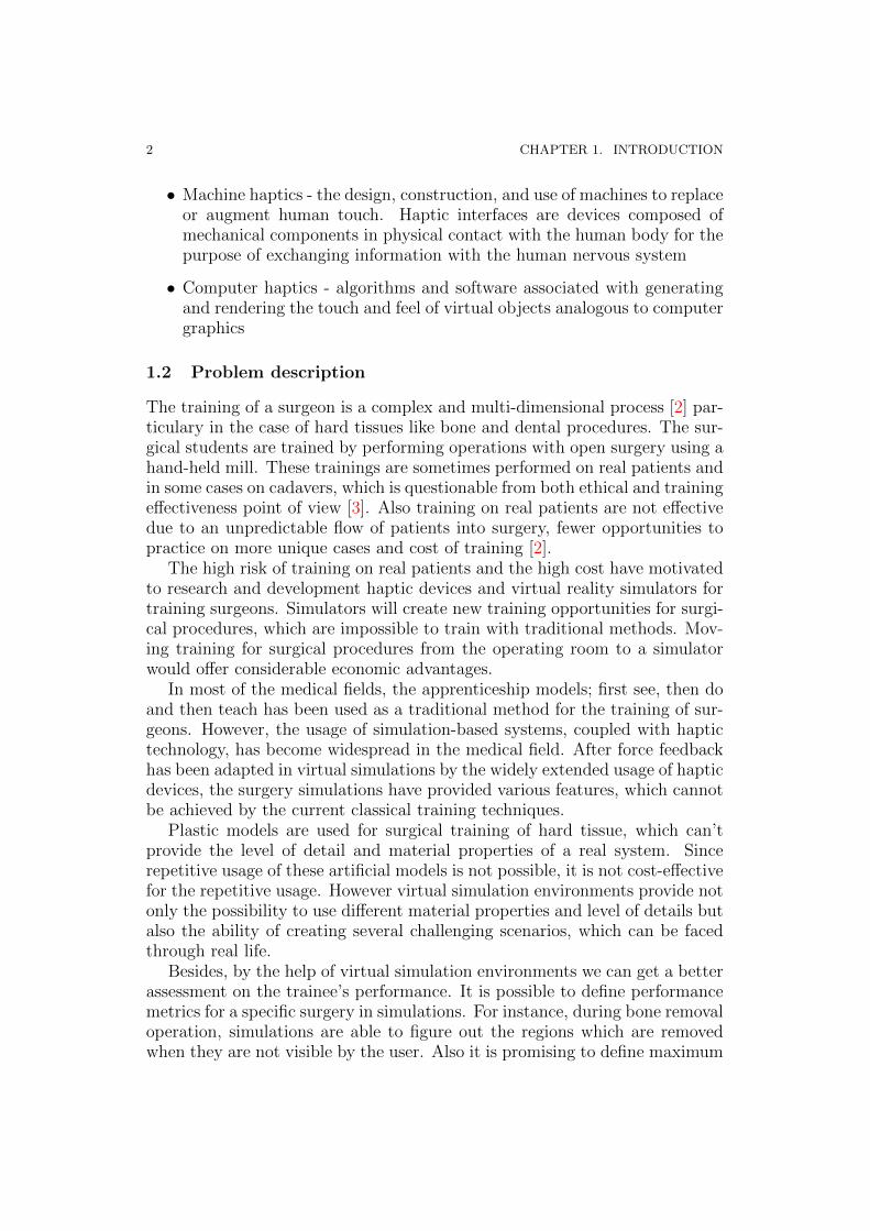
Considering the application context of a haptic device in orthopaedic anddental surgery, the surgeon needs to perform various tasks like cutting, millingand drilling as shown in Fig.1.1.
Fig. 1.1 – Typical tasks involved in a surgery of hard tissues, [4],[5].
In order to create a haptically-enabled virtual reality simulator to trainsurgeons for these skills, the main requirements are given in [6], which are asfollows.
• Haptic feedback in 6-DOF, to allow both force and torque feedback aswell translational and rotational capabilities of the virtual tool operatingin a (narrow) channel or cavity
• The whole device should fit in a space of 250 × 250 × 300 mm
• The minimum translational and rotational workspace should be 50 × 50× 50 mm and ±40o respectively in all directions at the nominal position,with no singularities in the workspace
• The tool center point (TCP) should be able to render high force andtorque up to at least 50 N and 1 Nm, respectively
• Low back-drive inertia and friction, and no constraints on motion imposedby the device kinematics, so that free motion feels free
• Ergonomics and comfort for the user
• Transparency and stability of the complete system

4 CHAPTER 1. INTRODUCTION
Some of the common characteristics which are considered desirable forforce/torque feedback haptic devices include according to [7]:
• Isotropic behaviour
• Large workspace
• Low effective mass
• Symmetric inertia, friction, stiffness, and resonate frequency propertiesthereby regularizing the device so users don’t have to compensate forthese forces
• Robustness
• Balanced range, resolution, and bandwidth of position sensing and forcereflection
• Proper ergonomics that eliminate pain and discomfort when manipulat-ing the haptic interface
Ideally, these design specifications can be transformed into quantitativeperformance measures like workspace, manipulability, payload, inertia andstiffness, where it is desirable to obtain a parametric relationship to criticaldesign parameters of the device.
1.3 Research objective and questions
The main objective of this research has been to investigate, if model-baseddesign can be an efficient tool to develop haptic devices that can be used forsimulation of surgical procedures of hard tissues. We have chosen to focus oninvestigating the following questions:
• What is the available number of degrees of freedom, and what is theactual workspace of the concept being studied?
• How can we optimize haptic devices for optimal performance?
• How should we model the stiffness of haptic devices?
1.4 Research approach
Development of haptic devices is a challenging task because of the multi-criteria design consideration. The approach used in this thesis is to apply amodel-based design approach on some relevant evaluations that are needed.
First, existing literature was reviewed to identify the main design require-ments, which have considerable effects on the overall performance of hapticdevices. Thereafter, the focus was set to evaluate some of these requirements,

1.5. DELIMITATION 5
e.g. workspace, isotropy and stiffness. Then the model-base approach wasused and models necessary for these evaluations were developed. The ap-proach that has been used here is shown in the top part of Fig.1.2.
Models
Devlopment
Models
Verification
Kinematic
ModelMBS Adams/
Maple SimDynamic Model
Stiffness Model
Analytical
Ansys
Experimental
GA
NSGA
Performance
Indices
Performance
Indices
Design
Optimizaton
Performance
Evaluation
Sensitivity
Analysis
PrototypePrototype
Evaluation
Fig. 1.2 – Research approach.
First models for the specific evaluations are developed and verified (firsttwo boxes), then based on the situation these models can also be used for for-mulation of performance indices and later in the multi-objective optimization.The lower part of Fig.1.2 shows the models that have been developed in thiswork to investigate the model-base design approach.
1.5 Delimitation
The research presented in this thesis mainly focuses on model-based designof haptic devices. This has been applied on the current ongoing project atthe System and Component Design division and Mechatronics division, atKTH[3],[8]. In this model-based design approach we have only consideredkinematic, dynamic and stiffness models for design evaluation. The frictionand joint clearance models are not treated.
1.6 Thesis outline
The thesis is organized in five chapters including the introductory chapter.The thesis is outlined as follows, chapter 2 presents the state of the art ofhaptic devices. Chapter 3 presents model-based design. Chapter 4 presents asummary of the appended papers and finally Chapter 5 presents discussion,conclusions and future work.


Chapter 2
State of the art
Several studies exist on design and devolvement of haptic devices in commer-cial and academic literature. In this chapter, a brief review is given aboutcomparison of different haptic devices, design and modelling approaches. Acomparative study has been conducted by S.Khan [8], in which he compareddifferent haptic devices based on configuration, DOF, workspace, stiffness,maximum force and cost. Currently, there are haptic devices available in formof 2, 3, 4, 5, 6, 7-DOF reviewed by e.g. G. Gogu [7] and F.Lee [5]. F.Lee hascompared different haptic devices based on serial and parallel configurationsas shown in Fig.2.1 and Fig.2.2. An overview of this comparison is made inthe next section.
Fig. 2.1 – Haptic devices based on serial configuration [5].
7

8 CHAPTER 2. STATE OF THE ART
Fig. 2.2 – Haptic devices based on parallel configuration [5].
2.1 Serial, parallel and hybrid haptic devices
Serial devices adopt a design by connecting arms one by one in series by varioustypes of joints, especially revolute and prismatic. One end of the manipulatoris connected to the ground, and the other end is free to move in space. Forthis reason, a serial manipulator is also referred as an open-loop manipulator.Serial devices possess a some advantages like large working volume and highdexterity; however numerous disadvantages such as low precision, poor forceexertion capability, low payload-to-weight ratio, and high inertias tend to limitits use in many applications.
Parallel devices in contrast to serial one are closed-loop mechanism wherethe end-effector is connected to the base by at least two independent kinematicchains. Parallel devices possess high stiffness, low inertia, high rigidity andaccuracy, and high payload-to-weight ratios, which enable large bandwidthtransmission of forces but with some disadvantages like small workspace, pos-sibilities of singularity due to link collision and low dexterity.
Recently, many six degrees of freedom (DOF) haptic devices have beendeveloped, some of which have been commercialized [9]. These include serial-mechanism-based devices, such as the PHANTOM Desktop and PHANTOMOmni by SensAble technologies [10] that provide a large workspace of 160 ×120 × 120 mm, with a stiffness of 2.35 N mm−1 and a force of 7.9 N for stiffcontacts; similarly, the HAPTION [11] Virtuose 6D35-45 and Virtuose 3D15-25 provide a workspace of 450 mm and a maximum force of 35 N. These devices

2.2. OPTIMIZATION 9
provide insufficient stiffness and force/torque capacity for stiff contacts andare not suitable in case of interaction with hard tissues. Many researchers haveproposed parallel-mechanism based haptic devices due to their high stiffnessand accuracy. Six-DOF Delta and Omega haptic devices from Force Dimen-sion [12], a modified Delta device and Haptic master developed by Tsumaki etal. [13], a 6-URS parallel haptic device developed by J.M. Sabatera et al. [14],and a new 6-DOF haptic device developed at CEA-LIST [15], all for desktopapplications, are some examples of parallel mechanisms. However, all thesedevices have the drawback of having either a small workspace or low stiffness.
Research is therefore focusing on hybrid mechanisms that combine the ad-vantages of parallel and serial mechanisms to obtain sufficient stiffness, enoughworkspace, and a compact design. Hybrid devices aim to combine the bestcharacteristics of a serial and parallel device, with large workspace, high dex-terity, high stiffness and high payload-to-weight ratios and high precision.Hongliang Cui et al. [16] have worked on the kinematic analysis and errormodeling of a new 3-DOF mechanism based on a serial-parallel mechanism,called 3-DOF TAU parallel robot. Zhenqi Zhu et al. [17] have developedkinematic and dynamic modeling for real-time control of TAU parallel robot.However, no effort has been made to develop the kinematics of 6-DOF TAUdevices. Various models of 6-DOF TAU devices have been developed andanalyzed by Khan et al. [6] to identify their best characteristics.
2.2 Optimization
The performances of these devices are highly dependent on optimum struc-tural and geometric parameters of the device. Furthermore, numerous designaspects contribute to the performance, and an efficient design will be onethat takes into account all or most of these design aspects. This is an iter-ative process, and an efficient design requires a lot of computational effortsand capabilities for mapping the design parameters into design criteria, andhence into a form of multi-objective design optimization problem [18]. In theoptimization, multiple criteria such as, for example, workspace; kinematic per-formance indices like kinematic isotropy; static force transmission capability;stiffness; and dynamic performance needed to be considered [8].
Finding an optimal solution for these devices entails handling a multi-criteria optimal design problem; that is, a multi-objective constrained nonlin-ear optimization problem with no explicit analytical expression. The gradientand Hessian algorithms that generally converge to a local minimum are notsuitable for solving this problem. An interval-analysis based approach hasrecently been used to solve a multi-criteria design problem for parallel manip-ulators by Hao and Merlet [19]. This approach determines a design parameterspace that satisfies all design constraints. However, this approach requiresexplicitly analytical expressions of all constraints. The performance-chart-

10 CHAPTER 2. STATE OF THE ART
based design methodology (PCbDM) proposed by Xin-Jun Liu et al. [20] isan optimal kinematic design methodology for parallel mechanisms with fewerthan five linear parameters, which is unsuitable for our optimization problemwith its five design parameters. In this regard, the genetic algorithm (GA)[21], approach seems a good option for multi-criteria problems due to its goodconvergence property and robustness. Stan et al. [22], J.H. Lee et al. [23],S.S. Lee and J.M. Lee [24], Hwang et al.[25], Raza.R et all. [26] and Khan etal. [9] have used a GA approach for the multi-criteria optimization of parallelkinematics machines and parallel haptic devices.
2.3 Stiffness modelling
Mechanical stiffness is one of the most important indicators in performanceevaluation of robotic systems [27, 28, 29]. In particular, for haptic devices,where the primary target is the precise manipulation of a tool centre point,precise stiffness identification and compensation play an important role duringthe design process.
Stiffness analysis has been widely investigated in the literature. Severalmethods exist for computation of the stiffness matrix: the virtual joint method(VJM), that is often called the lumped modeling [30, 31, 32, 33, 34], finiteelement analysis (FEA) [34, 35, 36] and matrix structural analysis (MSA)[37, 38, 39, 40]. Uchiyama [41] has derived an analytical model for the stiff-ness of a compact 6-DOF haptic device based on static elastic deformation ofcompliance elements.
Moreover, in order to obtain a more realistic stiffness model the existingstiffness models should be complemented with more complex effects such asjoint stiffness, that also degrade the positioning accuracy. When it comes tothe compliance of joints, they are mostly modeled as a constant stiffness andapplied only for active joints. Bonnemains et al. [42] e.g. have considered thestiffness of spherical joints in the stiffness computation and identification ofkinematic machine tools.
Common to all the described modeling methods is that they all need apractical validation by means of experimental testing of a prototype. CharlesPinto et al. [43] have evaluated static stiffness mapping of their Lower MobilityParallel Manipulator. They used pre-loading in the experimental testing toeliminate backlash in the system. In experimental testing [44], the staticbehavior evaluation of a robot was analyzed by norms, e.g. ANSI/RIA R15.05-1-1990 [45], ISO 9283:1998 [46], which were established for serial manipulators.

Chapter 3
Model-based design
This chapter presents a model-based design approach for design of hapticdevices. The basic objective of this approach is to develop a haptic device,which has high stiffness, large workspace, high manipulability, small inertia,low friction and high transparency. The functional requirements are derivedfrom the user and device requirements, described in section 1.2, and are thebasis for generating the design concept as shown in Fig.3.1. The properties ofthis concept are then evaluated using a model based design, as shown on theright side of Fig.3.1. The overall objectives of the haptic device is to resemblea real situation, when manipulating objects in a remote or virtual world.
Workspace
Manipulability
Payload
Stiffness
Inertia
Friction
Backlash
Payload
Friction
ModelControl
Design
Singularity
free
workspace
Manipulabili
ty
Workspace
Design
concept
DOF
Functional
requirements
Stiffness
Model
Dynamic
Model
Kinematic
Model
Jacobian
Matrix
Joint
clearance
Model
· User
requirements
· Device
requirements
Fig. 3.1 – Dependencies between functional requirements, design concept and models neededfor evaluation of product properties.
Carbone Giuseppe et al. [47] have used model-based design approachand multi-criteria requirements for multi-objectives optimization of CaPaMan(Cassino Parallel Manipulator). He considered kinematic, static, dynamic,
11

12 CHAPTER 3. MODEL-BASED DESIGN
friction, stiffness and joint clearance models for formulating the optimizationproblem, but due to computational complexity, he managed to include onlykinematic and stiffness models in the optimization.
Furthermore, numerous design aspects/attributes contribute to the perfor-mance of haptic devices, like large workspace, high manipulability/isotropy,torque requirements on an actuator for unit force/torque applied, high stiffnessfor precise positioning, low inertia and low resonant frequency. This turns outto be a multi-criteria problem, which is addressed by a model-based designapproach for evaluating concept properties. In Fig.3.1, a selection of theserequired properties and models needed to evaluate them are illustrated.
The main requirements considered in this thesis are DOF, workspace, ma-nipulability/isotropy, torque requirements on actuators, structural stiffnessand dynamics. The models which are needed to evaluate these requirementsare the kinematic, stiffness and dynamic models. The friction and joint clear-ance models are not considered in this thesis. Some of these models are mutu-ally dependent, thus leading to a computationally complex evaluation. In thecoming sections a case study is used to illustrate the evaluation of the abovediscussed requirements.
3.1 Degrees of freedom
The first concern in the study of kinematics of a mechanism is the number ofdegrees of freedom. The degrees of freedom of a mechanism are the number ofindependent parameters or inputs needed to specify the configuration of themechanism completely. The Grubler criterion was used to find the number ofindependent coordinates of the system by using equation (3.1).
F = λ(n− j − 1)∑
i
fi (3.1)
WhereF : Degrees of freedom of the mechanism.λ : Degrees of freedom of the space in which a mechanism is intended tofunction.n : Numbers of links in mechanism including fixed link.j: No of joints in a mechanism, assuming that all the joints are binary.fi : Degrees of relative motion permitted by joint i.
3.2 Workspace
The workspace is one of the most important kinematic properties of manip-ulators, because of its impact on manipulator design and location within aworkspace. Different types of workspace are defined by G. Castelli et al.[48], such as reachable workspace, dexterous workspace and constant orienta-tion workspace. The kinematic model is the basis for the workspace analysis,

3.2. WORKSPACE 13
because the workspace depends upon the constraints on active and passivejoints, collision avoidance between the links and platform (end effector) andkinematic singularity.
In order to take into account the above-mentioned constraints and to deter-mine the workspace, we need a kinematic model of the device. In the comingsection, the kinematic model of a new 6-DOF haptic device based on TAUconfiguration is presented.
3.2.1 Kinematic model
Kinematics is the basis to the analysis of any robotic system. Once this modelis developed, the designer can evaluate the performance of the system. Thekinematic model is the core for other dependent models like dynamic and stiff-ness models, etc. A schematic model of kinematics of 6-DOF TAU is shownFig.3.2. The schematic model consist of three chains i = 1, 2, 3, where the twochains i = 1, 2 are symmetrical, while the third chain i = 3 is asymmetrical.These three chains have two active revolute joints with angles [θi1, θi2] , Fur-ther the two symmetrical chains have two passive universal joints with angles[φi1, φi2, φi3, φi4] for i = 1, 2 , while the third chain has a passive revolute
joint with angle φ31. The kinematic model consist of two sub-models i.e., theinverse kinematic and forward kinematic model.
{N}
{P}X
Z
Y
1.5 d
1.5 d
1.5 d L1
L2
1112
2221
31
32
1a
1b
1c
1d
1e
2e
2c
2d
2b2a
3c
3b3a
12
11
13
14
21
22
23
24
31
X
Y
Z
Fig. 3.2 – Schematic model of 6-DOF TAU

14 CHAPTER 3. MODEL-BASED DESIGN
Inverse kinematics
The inverse kinematic problem for the proposed 6-DOF TAU configurationdetermines orientation of active joint angles [θi1, θi2] and passive joint angles[φi1, φi2, φi3, φi4] , while the pose (position and orientation) [px, py, pz, α, β, γ]
of the platform are given. A closed-form solution for the inverse kinematicscan be found based on the constrain equations.
There are two constrain equations for symmetrical chains according to thepath (ai, bi, ci) and (ai, bi, di, ei), as given in equation (3.2) and (3.3). A de-tailed about formulation of these active and passive joint angles are given in(Paper A).
(cix − bix)2 + (ciy − biy)2 + (ciz − biz)2 = L22 (3.2)
(dix − eix)2 + (diy − eiy)2 + (diz − eiz)2 = L22 (3.3)
Forward kinematics
The forward kinematics problem for the proposed 6-DOF TAU configurationdetermines the pose [px, py, pz, α, β, γ] , of the platform, while the orienta-tions (i.e., joint angles) [θi1, θi2] with i = 1, 2, 3 of all actuators are given. Noclosed-form analytical solution is available for the forward kinematics of the6-DOF TAU configuration, due to the complex nonlinear equations. There-fore, the Newton-Raphson numerical approximation method is used to solvethe forward kinematics problem. The Newton-Raphson approximation of thesolution is given by equation
Xn+1 = Xn − [F ′(Xn)]−1F (Xn) (3.4)
Where Xn is the initial guess value of the platform pose [px, py, pz, α, β, γ] ,while Xn+1 is the solution to be determined through function F (Xn), andits derivative F ′(Xn)F (Xn) is defined separately for each kinematic chain.The functions are defined for each serial chain by differentiating the closeequations (3.2) and (3.3). For each serial chain, this function is defined fromjoint position ci, di of the platform, in case of θi1 = f(cix, ciy, ciz) and θi2 =f(cix, ciy, ciz, eix, eiy, eiz), so
θi1 = Jsi1ci, Jsi1 ∈ 1× 3 (3.5)
WhereJsi1 =
[∂Fi1
∂cix
∂Fi1
∂ciy
∂Fi1
∂ciz
]
And
ci =[
∂cix∂t
∂ciy∂t
∂ciz∂t
]T
Whileci = Jpi1X, Jpi1 ∈ 3× 6 (3.6)
3.2. WORKSPACE 15
The element of jacobian for θi1 can be find by putting equation (3.6) into (3.5)as given in equation (3.7).
θi1 = Jsi1Jpi1X = Ji1X (3.7)
Here X = [px, py, pz, α, β, γ] and Ji1 ∈ 1× 6The same procedure can be used for θi2 as the one used for θi1, while in
this case Jsi ∈ 1× 6 and Jpi ∈ 6× 6, so
θi2 = JsiJpiX = Ji1X (3.8)
Jsi =[
∂Fi2
∂cix
∂Fi2
∂ciy
∂Fi2
∂ciz
∂Fi2
∂diz
∂Fi2
∂diz
∂Fi2
∂diz
]
And
ci =[
∂cix∂t
∂ciy∂t
∂ciz∂t
∂dix∂t
∂diy∂t
∂diz∂t
]T
This is in the case when i = 1, 2.In case of i = 3 both active joint angles are function of θi1, θi2 = f(cix, ciy, ciz),
so equation (3.7) is used to find the elements of the jacobian matrix for θi1and θi2. The jacobian of the complete system is given as
θi = JXi, J ∈ 6× 6 (3.9)
3.2.2 Workspace analysis
When we have developed the kinematic model of the selected concept thatwe are evaluating, we can perform a workspace analysis. A general numer-ical evaluation of the workspace can be deduced by formulating a suitablebinary representation of a cross-section. A cross-section can be obtained witha suitable scan of the computed reachable positions and orientations, once theinverse kinematic problem has been solved as function of position and orien-tation of the TCP of the platform, A binary variable Fij can be defined onthe cross-section plane for a cross-section of the workspace as follows: if the(i,j) grid pixel includes a reachable point, then Fij = 1 ; otherwise Fij = 0, asshown in Fig.3.3.
Reachable workspace
The reachable workspace (constant orientation) describes the volume in spacewithin which the manipulator’s end effector centre point can reach. The reach-able workspace is described in equation(3.10)
V =
x∫
x0
θ∫
θ0
r∫
r0
Fijrdrdθdx (3.10)

16 CHAPTER 3. MODEL-BASED DESIGN
dθ
θ
rdr
dx
dx
Y
Z
X
Y
Z
dθ
dr
θ
r
I,j
I,j-1
i-1,j-1
i-1,j
Fij
Fij
Fig. 3.3 – Workspace
where dr = ri− ri−1 and dθ = θj− θj−1, and Fij is a flag value depends theconditions given in equation(3.11)
Fij =
{1 if Fij ∈ W (X, Y, Z)
0 if Fij /∈ W (X, Y, Z)(3.11)
Here W is the grid points of workspace traversed by TCP with constant ori-entation of platform.
Dexterous workspace
The dexterous workspace is a subset of reachable workspace, which also con-sider orientational reachability of the workspace. It is defined as the workspacethat is reachable by all the required maximum orientations at that point.To calculate dexterous workspace, the manipulator is traversed in workspaceshown in Fig.3.3, and at each grid point in the workspace the prescribed rota-tions are applied. If any of the constraints on active or passive joints given inequation (3.12) and (3.13) , or kinematic singularity given in equation (3.14)is not satisfied at any of the rotations. The grid point is not within workspace.The algorithm work by assigning binary numbers (0,1) to two flags flag1 andflag2. If at each grid point both the flags are 0, the point is within theworkspace, otherwise not. The dexterous workspace is calculated by the same

3.3. MULTI-OBJECTIVE DESIGN OPTIMIZATION 17
equation(3.10), but with the following conditions as given in equation(3.15)
min(θii) ≤ θii ≤ max(θii) (3.12)
min(φii) ≤ φii ≤ max(φii) (3.13)
det(J) 6= 0 (3.14)
Fij =
{1 if Fij ∈ W (X, Y, Z, α, β, ζ)
0 if Fij /∈ W (X, Y, Z, α, β, ζ)(3.15)
Here W is the grid points of workspace traversed by TCP with orientationof platform in X, Y, Z−directions with total of 3n rotations at each grid point,when n is the no of rotation in one direction. An algorithm that calculatesthe dexterous workspace is given in Fig.3.4.
3.3 Multi-objective design optimization
As the performance of hybrid mechanisms is highly sensitive to their geom-etry and dimensions, design optimization is an important step in the designprocess. The main objective of the design optimization is to find the best com-promise between kinematic performance indices like workspace, isotropy, forcerequirement based on the device requirements in the beginning of this chap-ter. Various performance requirements are mentioned, but the investigationreported in this thesis is focuses mainly on three basic performance indices,namely workspace volume; kinematic isotropy, and static torque requirements.The volume index of the device is defined using the inverse kinematic model,while the other two indices are defined on the basis of the Jacobian matrixdiscussed in section 3.2.1.
The workspace of a robot is a crucial criterion in comparing manipulatorgeometries. Reachable and dexterous workspace are used to characterize theworkspace of a robot manipulator. The goals of an optimal design is to achievethe largest possible volume for both dexterous workspace and the reachableworkspace, high isotropy and small static torque on the actuators. There isa close relationship between the kinematics performance and the manipulatorstructure. This is an iterative process, and an efficient design requires a lotof computational efforts and capabilities for mapping design parameters intodesign criteria, and hence turning out with a multi-objective design optimiza-tion problem. The solutions of such a problem are no dominated solutions,also called Pareto-optimal solutions. Accordingly, a multi-objective design op-timization approach is proposed based on performance measures/criteria fromkinematic.

18 CHAPTER 3. MODEL-BASED DESIGN
3.2. WORKSPACE 17
Here W is the grid points of workspace traversed by TCP with orientationof platform in X, Y, Z−directions with total of 3n rotations at each grid point,when n is the no of rotation in one direction. The algorithm to calculate thedexterous workspace is given in the Algorithm 3.2.1,
Algorithm 3.2.1: Workspace Algorithm()
for x← xmin to xmax
do
for θ ← θmin to θmax
do
for r ← rmin to rmax
do
y = rcosθz = rsinθflag1 = 0flag2 = 0for R← Rmin to Rmax, R =
[Rx Ry Rz
]
do
if flag1 = 1
then
{flag2 = flag1break
else
then
calculate, θiif θi < θmin ∩ θi > θmax
then
flag1 = 1flga2 = flag1break
calculateJacobian, Jif det(J = 0)
then
flag1 = 1flga2 = flag1break
else
then
if flag1 6= 1then
flag2 = 0if flag1 = 0 ∩ flag2 = 0
then
{
The point is within the Workspacereturn (r)
return (θ)return (x)
Fig. 3.4 – Workspace algorithm

3.3. MULTI-OBJECTIVE DESIGN OPTIMIZATION 19
3.3.1 Optimization objectives
The multi-objective optimization problem aims to determine the optimum ge-ometric parameters of the TAU haptic device in order to maximize its dexter-ous workspace volume index VI, global isotropy index GII, and global torquerequirement index GTRI. These indices are given in detail in (Paper B). Here,the workspace of the mechanism is discretized and the considered performancemeasures and constraints are evaluated and verified for each point.
For the studied TAU haptic device, we use the min-max fuzzy logic to de-fine the objective function. The optimization problem can be formulated asto find the optimum design parameters x of TAU haptic device in order tomaximize the volume VI, global isotropy index GII and minimize the torquerequirement index GTRI of the mechanism, subject to some design constraintson the active, passive joints and singularity, i.e when the determinant of kine-matic Jacobian matrix becomes zero. Finally, a multi-criteria design objectivefunction is defined in equation (3.16), as follows
GDI = min
[GII
GIIm,GTRImGTRI
,V I
V Im
](3.16)
where subscript m represents value of the design indices corresponding tothe mid values of the input design parameters. The main idea underlying thisapproach is to make the indices dimensionless, to ensure that all design indicesare equally active in the optimization process.
Mathematically, the problem can be written as in the form of equation(3.17):
maximizex
GDI(x)
over x = [L1, L2, Rp, d, θ32]
subject to min(θii) ≤ θii ≤ max(θii)
min(φii) ≤ φii ≤ max(φii)
xlb ≤ xi ≤ xupdet(J) > 0
(3.17)
where xlb and xup are the lower and upper bound of the design parametersxi respectively.
Multi-objective Genetic Algorithm
Optimization of 6-DOF TAU haptic is complex, due to multi-objective, multi-constraints and an increase in the number of design parameters. A reasonableapproach to such a problem is to investigate a set of solutions, each of whichsatisfies the objectives at an acceptable level without being dominated by anyother solution. This is called a Pareto optimal solution. To find the Pareto

20 CHAPTER 3. MODEL-BASED DESIGN
optimal solution, we used a multi-objective genetic algorithm (MOGA-II) [49]and non-dominated sorting based genetic algorithm (NSGA-II) [50].
Non-dominated Sorted Genetic Algorithm
The NSGA-II algorithm proposed by Deb et al. [50] is a new version of theNSGA algorithm. NSGA-II incorporates elitism and crowding distance. Thepopulation is initialized as usual. Once the population has been initialized,the population is sorted into fronts on the basis of non-domination. Thefirst front is the completely non-dominant set in the current population. Thesecond front is dominated by the individuals in the first front only. Subse-quent fronts are defined in the same fashion. Each individual in each front isassigned rank (fitness) values based on the front to which they belong. Indi-viduals in the first front are given a fitness value of 1, individuals in the secondare assigned a fitness value of 2, and so on. In addition to fitness values, anew parameter called crowding distance is calculated for each individual. Thecrowding distance is a measure of how close an individual is to its neighbors.Large average crowding distances will result in better diversity in the popu-lation and thus improve the performance of the algorithm when calculatingthe Pareto optimum. The operation of NSGA-II in calculating the Paretooptimum is described in detail in [50, 51].
3.4 Dynamic model
The Lagrange method describes the dynamics of a mechanical system fromthe concepts of work and energy. The general equation for Lagrange dynamicformulation is
d
dt
(∂L
∂qi
)− ∂L
∂qi= τ (3.18)
Where L = K−P , is the Lagrange function, K and P are the total kineticand potential energy of the system, qi is generalized coordinates [px, py, pz, α, β, γ],and qi is corresponding velocity of generalized coordinates.
3.4.1 Lagrange equation in joint space
In order to derive the joint torques, we will use the transpose of the inverse ofJacobian matrix as given in equation.
τj = J−T τC (3.19)
The equation of motion that shows the torques on actuators in the jointcoordinate system is expressed as
M(θ)θ + V (θ, θ) +G(θ) = τJ (3.20)

3.5. STIFFNESS MODEL 21
where the first term M(θ) in equation represents inertial forces, while the
second term V (θ, θ) accounts for the Coriolis and centrifugal forces and thelast term G(θ) on the left side is the gravity force, while τJ is the generalizedCartesian forces/torques at the end-effector. A detailed of formulation ofdynamics equations are given in (Paper A). Furthermore
θi = Jqi and
θi = Jqi + J qi
3.5 Stiffness model
As it has been previously pointed out in chapter 1, the design of haptic devicesin not trivial due to its complex design, multi-domains consideration and infinding the best compromise between several properties, such as workspace,dexterity, manipulability, and stiffness. Stiffness is an essential performancemeasure since it is directly related to the positioning accuracy and payloadcapability of haptic devices. To make these devices compatible with theirapplications, it is necessary to model, identify and compensate all the effectsthat degrade their accuracy. Stiffness can be defined as the capacity of amechanical system to sustain loads without excessive changes of its geometry.These produced changes on geometry, due to the applied forces, are knownas deformations or compliant displacements [52]. Compliant displacementsin a robotic system produce negative effects on static and fatigue strength,wear resistance, efficiency (friction losses), accuracy, and dynamic stability(vibration).
In this thesis, a systematic procedure is proposed to develop a generalizedstiffness model of the manipulator and its evaluation with virtual (FEM anal-ysis) and physical experiments. To develop this, a work procedure defined bythe flowchart in Fig.3.5 is presented.
The procedure established by this flowchart is as follows:The approach used in this methodology is to start with a simplified ana-
lytical model. This is compared (verified) by a simplified FEM model in aniterative way until these two models come into close agreement with results.Thereafter, a simplified physical experiment is made to validate the analyticalmodel. If the difference between the analytical and the experimental resultsis not acceptable, i.e. it doesn’t validate the analytical model, a more detailedanalytical model has to be developed.
For the detailed analytical model also the passive joints and actuation sys-tem are included. This is then verified with a detailed FEM model withcorresponding detailing level in the same way as for the simplified model.Thereafter, this detailed analytical model is validated by means of a detailedphysical experiment. After validating the proposed model, a sensitivity anal-ysis is performed to map the variation of static stiffness in the workspace. In

22 CHAPTER 3. MODEL-BASED DESIGN
Simplified Analytical Model
Start
Simplified FEM Model
FEA=Simplified Anaytical
Simplified Physical experiments
Yes
Physical experiments= Simplified FEA=Simplified Anaytical Model
Detailed Analytical Model
No
Detailed FEM
Detailed Physical Experiments
No
Detailed FEA=Detailed Anaytical Model
Physical experiments= Detailed FEA=Detailed Anaytical Model
Sensititvity Analysis
yes
Simplification based on contributions
Design Optimization and RoubustnessStiffness compensation in control
Model parameters adjustment and
hypothesis revision
No
Model parameters adjustment
No
Simplified Modelling
Detailed Modelling
Fig. 3.5 – Stiffness modeling methodology
these maps, the engineering stiffness is visualized as a function of the gener-alized coordinates of the workspace. A detail description of this methodologyis given in (Paper C).
A general stiffness model for N number of compliant elements serially con-

3.6. MODEL VERIFICATION 23
nected with each other is given in equation(3.21),
0CN =0 JN−1N−1S
N−1N J0 + ......
0NJN−1,disp(
0JN−2N−2S
N−2N−1J0)0
NJN−1,force + .....+0NJi,disp(
0J i−1i−1S
i−1i J0)i0JN,force + .....
+0NJ1,disp(
0J01S
11J0)0
1J1,disp
(3.21)
Where 0CN is the compliance of the complete system, 0JN−1 representscoordinate transformation Jacobian between local frame N−1 and 0, i0JN,forceis the force transformation Jacobian matrix which transforms the coordinateof application of the force vector from coordinate N to reference coordinateU , and 0
NJi,disp is the displacement transformation Jacobian which transformsthe displacement from 0 to N . Where 0S1 represents the compliance matrixin local frame.
3.6 Model verification
To verify the developed kinematic, dynamics and stiffness models, the firsttwo models were verified in MapleSim [53], while the third model was verifiedby both FEM analysis (Ansys[54]) and physical experiments. The MapleSimmodel is shown in Fig.3.6.
X
Z
Y
Fig. 3.6 – MapleSim model
24 CHAPTER 3. MODEL-BASED DESIGN
3.6.1 Kinematic model
In order to validate the inverse kinematic model developed in section 3.2.1,an input trajectory of sin(ωt) was applied in the rotational degree of freedomalong the x-axis. The results from both analytical model and MapleSim modelare shown in Fig.3.7. By comparing these results, we can validate the inversekinematics calculation approach that has been presented in section 3.2.1. Theresults in Fig.3.7 shows that analytical model agrees with the MapleSim model,which verify the validity of the model.
3.6.2 Dynamic model
The dynamic model was verified using the same trajectory sin(ωt) on theactuators, and the required torques on the actuators were calculated basedon the analytical dynamic model of section of 3.4 and MapleSim model. Theresults from these analysis are shown in Fig.3.8, where we can conclude thatthe results from the analytical model agree the MapleSim model.
3.6.3 Stiffness model
The stiffness model developed in section 3.5 is validated through simulationusing Ansys and physical experiments. A detailed description about validationis given in (Paper C); some of the results are shown in Fig.3.9.

3.6. MODEL VERIFICATION 25
0 0.5 1 1.5 2 2.5 3 3.5 4 4.5 5−52
−51
−50
−49
−48
−47
−46
−45
−44
Time(s)
θ 11 (
deg)
AnalyticalMaple
(a) Rotation of actuator 1
0 0.5 1 1.5 2 2.5 3 3.5 4 4.5 5−15
−10
−5
0
5
10
15
Time(s)θ 12
(de
g)
AnalyticalMaple
(b) Rotation of actuator 2
0 0.5 1 1.5 2 2.5 3 3.5 4 4.5 544
45
46
47
48
49
50
51
52
Time(s)
θ 21 (
deg)
AnalyticalMaple
(c) Rotation of actuator 3
0 0.5 1 1.5 2 2.5 3 3.5 4 4.5 5−15
−10
−5
0
5
10
15
Time(s)
θ 22 (
deg)
AnalyticalMaple
(d) Rotation of actuator 4
0 0.5 1 1.5 2 2.5 3 3.5 4 4.5 5−6
−4
−2
0
2
4
6
Time(s)
θ 31 (
deg)
AnalyticalMaple
(e) Rotation of actuator 5
0 0.5 1 1.5 2 2.5 3 3.5 4 4.5 5−24.5
−24
−23.5
−23
−22.5
−22
−21.5
−21
Time(s)
θ 32 (
deg)
AnalyticalMaple
(f) Rotation of actuator 6
Fig. 3.7 – Comparison of Inverse kinematics by analytical and MapleSim

26 CHAPTER 3. MODEL-BASED DESIGN
0 0.5 1 1.5 2 2.5 3 3.5 4 4.5 5−2.5
−2
−1.5
−1
−0.5
0
0.5
1
1.5
2
Time(s)
τ 11 (
Nm
)
AnalyticalMaple
(a) Torque on actuator 1
0 0.5 1 1.5 2 2.5 3 3.5 4 4.5 5−16
−14
−12
−10
−8
−6
−4
−2
0
2
4
Time(s)τ 12
(N
m)
AnalyticalMaple
(b) Torque on actuator 2
0 0.5 1 1.5 2 2.5 3 3.5 4 4.5 5−2
−1.5
−1
−0.5
0
0.5
1
1.5
2
Time(s)
τ 21 (
Nm
)
AnalyticalMaple
(c) Torque on actuator 3
0 0.5 1 1.5 2 2.5 3 3.5 4 4.5 5−20
−15
−10
−5
0
5
10
Time(s)
τ 22 (
Nm
)
AnalyticalMaple
(d) Torque on actuator 4
0 0.5 1 1.5 2 2.5 3 3.5 4 4.5 5−0.25
−0.2
−0.15
−0.1
−0.05
0
0.05
0.1
0.15
0.2
0.25
Time(s)
Tor
que
(Nm
)
AnalyticalMapleSim
(e) Torque on actuator 5
0 0.5 1 1.5 2 2.5 3 3.5 4 4.5 510
11
12
13
14
15
16
Time(s)
Tor
que
(Nm
)
AnalyticalMapleSim
(f) Torque on actuator 6
Fig. 3.8 – Comparison of Torque on actuators from Analytical and MapleSim

3.6. MODEL VERIFICATION 27
0 1 2 3 4 5 6 7 80
0.05
0.1
0.15
0.2
0.25
0.3
Points in workspace
Def
lect
ions
in X
[mm
]
AnalyticalAnsysExperimental
(a) Deflection of platform in x-direction.
0 1 2 3 4 5 6 7 80
0.05
0.1
0.15
0.2
0.25
0.3
Points in workspace
Def
lect
ions
in Y
[mm
]
AnalyticalAnsysExperimental
(b) Deflection of platform in y-direction.
0 1 2 3 4 5 6 7 8−0.02
−0.01
0
0.01
0.02
0.03
0.04
0.05
0.06
0.07
0.08
Points in workspace
Def
lect
ions
in Z
[mm
]
AnalyticalAnsysExperimental
(c) Deflection of platform in z-direction.
Fig. 3.9 – Deflection of platform in x,y and z-direction.


Chapter 4
Summary of appended papers
This chapter gives a brief review of the appended papers.
4.1 Paper A: Kinematics and dynamics of a novel 6-DOF TAUhaptic device
This paper presents the kinematics and dynamics model of the TAU hap-tic device. First, a kinematic model for inverse and forward kinematics wasdeveloped and analyzed. Then an algorithm to solve the close form inversedynamics is presented using Lagrangian formulation. Numerical simulationwas carried out to examine the validity of the approach and accuracy of thetechnique employed. A trigonometric helical trajectory of 5th order spline wasused in Cartesian space for each degree of freedom of the moving platform inorder to verify and simulate the inverse dynamics of the device.
4.2 Paper B: Design Optimization of the TAU haptic device
In this paper, a multi-objective optimization (MOO) approach has been usedfor optimum design of a haptic device by optimizing kinematic performanceindices like workspace volume, isotropy and force/torque under constrain ofactive and passive joint angles, and singularity condition. For design optimiza-tion, performance indices such as workspace volume, kinematic isotropy andstatic torque requirements indices are defined. A new multi-criteria objectiveoptimization (MOO) function is introduced to define the optimization prob-lem. Multi-objective algorithms are used to solve this optimization problemusing the defined objective function. Furthermore, sensitivity analysis of theperformance indices against each design parameter is presented as a basis forselecting a final set of design parameters for the prototype. Finally, a CADmodel and prototype of the device is developed based upon the simulationresults.
29

30 CHAPTER 4. SUMMARY OF APPENDED PAPERS
4.3 Paper C: Stiffness modeling methodology forsimulation-driven design of haptic devices
This work proposes, a new methodology for creating an analytical and com-pact model for quasi-static stiffness analysis for haptic device, which considersthe stiffness of; actuation system; flexible links and passive joints. For themodeling of passive joints, a Hertzian contact model is introduced for bothspherical and universal joints, and a simply supported beam model for uni-versal joints. The validation process is presented as a systematic guideline toevaluate the stiffness parameters both using parametric FEM modeling andphysical experiments. Pre-loading has been used to consider the clearancesand possible assembling errors during manufacturing. A modified JP-Merletkinematic structure is used to exemplify the modeling and validation method-ology. The approach used in this methodology is to start with a simplifiedanalytical model. This is verified by a simplified FEM model in an iterativeway until these two models give the same results. Thereafter, a simplifiedphysical experiment is made to validate the analytical model. If the differ-ence between the analytical and the experimental results is not acceptable,i.e. it doesn’t validate the analytical model, a more detailed analytical modelhas to be developed. For the detailed analytical model also the passive jointsand actuation system are included. This is then verified with a detailed FEMmodel with corresponding detailing level in the same way as for the simplifiedmodel. Thereafter, this detailed analytical model is validated by means ofa detailed physical experiment. After validating the proposed model, a sen-sitivity analysis is performed to map the variation of static stiffness in theworkspace. In these maps, the engineering stiffness is visualized as a functionof the generalized coordinates of the workspace.

Chapter 5
Discussion, conclusions and futurework
The focus of the research presented in this thesis is to develop a model-baseddesign approach based on multi-criteria requirements for the design of hapticdevices, that can be used for simulation of surgical procedures of hard tissues.This chapter gives a discussion about the findings and presents conclusionsabout the investigated research questions.
5.1 Discussion
A kinematic model has been developed and verified using MapleSim. Theworkspace of the selected device has been analyzed both for reachable anddexterous workspace. An algorithm has been developed to analyze the dex-terous workspace. This can then be used in the design optimization to examineif this will effect the performance like manipulability, isotropy, stiffness andforce requirement index within the workspace.
The question is then; will we get better performance if we consider thedexterous workspace instead of constant orientation workspace during opti-mization?
To answer this question, we have investigated the use of dexterous workspaceinstead of reachable workspace during design optimization, and compared theresults in terms of two kinematic performance indices, isotropy and force re-quirement. The same design parameters were used, and the same workspacewere traversed. The results of kinematic isotropy and force requirement in-dices in the case of reachable workspace are 0.4374 and 1.7302 respectively,while in the case of dexterous workspace, these are 0.4619 and 1.6754 respec-tively. We also investigated the effect of workspace grid size on the kinematicperformance indices, and observed that changing the step size of the orien-tation from 5o to 1o can further improve the isotropy and force requirementindices up to 0.4690 and 1.6430 respectively as shown in Table.5.1. FromTable.5.1, it is clear that the use of dexterous workspace in optimization will
31

32 CHAPTER 5. DISCUSSION, CONCLUSIONS AND FUTURE WORK
increase the performance in terms of isotropy and force requirement on thecost of workspace.
Table 5.1 – Effect of workspace grid size on kinematic performance
5o 2.5o 1o Reachable
GII 0.4619 0.4630 0.4690 0.4374GTRI 1.6754 1.6767 1.6430 1.7302
VI 6.42E+05 6.42E+05 6.42E+05 7.80E+05
A methodology to create a generalized, highly compact and computation-ally efficient analytical stiffness model has been proposed. The proposed modelis obtained in a step by step modeling manner starting with a simplified modelconsidering the stiffness of all the compliant element within the system. Theproposed model takes into account the stiffness of the actuation system, lin-ear guideways, proximal links, and passive joints. The force acing at the TCPof the platform is decomposed into individual link forces, thereafter individ-ual link deflections are computed from the link stiffness properties. Finally,all these displacements are transformed and added to obtain the final globalcompliance matrix. The stiffness matrix is then calculated from the inverseof the compliance matrix. Another systems modeling approach covered bythe proposed methodology is the introduction of the Hertzian contact modelfor both spherical and universal passive joints and a simply supported beammodel for the universal joint.
A comparative analysis between the simplified modeling and detailed mod-eling were made, which shows that by considering the stiffness of passive joints,and actuation system reduces the relative error between analytical and exper-imental results from 83% to 16% and the average error from 79% to 8%. Acomparison of contributions of compliant element was made, which shows thestiffness of passive joints have a considerable effect on accuracy of the model.
5.2 Conclusions
(Paper A), addresses the first question in section 1.3. In this paper the inverseand forward kinematic model are developed for the TAU haptic device. Thesemodels are then used to calculate the reachable and dexterous workspace andto verify that 6-DOF can be obtained. The second question is addressedin (Paper B), where the kinematic model of (Paper A) has used as a ba-sis for defining performance indices, that were used in multi-objective designoptimization. From this paper we can conclude that optimization based onkinematic properties is an important part in the development of haptic de-vices. The last question about how to model the stiffness of a haptic deviceis addressed by (Paper C), where a methodology is outlined. This methodol-

5.3. FUTURE WORK 33
ogy gives a stepwise description of how to create and validate an analyticalstiffness model of haptic device.
5.3 Future work
• Stiffness evaluation of the TAU haptic device using the developed modelin (Paper C)
• Model based design optimization of the TAU haptic device by consideringthe requirements of inertia, dynamic properties(eigenfrequency) in (PaperA) and stiffness
• Development and verification of a friction model for haptic devices im-plemented on the Stewart-platform as well as the TAU structure
• Development of a model for precise singularity detection and avoidanceof TAU device
• Development of a backlash model for haptic devices based on Stewart-platform
• Accuracy evaluation of the complete system with compensation for in-ertia, friction and position errors cause by deflection using the stiffnessmodel developed in (Paper C)
• Evaluation of velocity and acceleration capabilities of the device


References
[1] M. srinivasan. what is haptics? [Online]. Available: http://www.sensable.com/support/phantom ghost/datafiles/what is haptics.pdf
[2] C. M. Salisbury, “Haptic hardware: Evaluation, design and placement,”Ph.D. dissertation, Stanford University, 2010. [Online]. Available:http://gradworks.umi.com/33/82/3382949.html
[3] M. G. Eriksson, “Haptic milling simulation in six degrees-of-freedom withapplication to surgery in stiff tissue,” Ph.D. dissertation, KTH, Stock-holm, 2012.
[4] Digital dentures: A complete game changer for local dental labs.[Online]. Available: http://www.capedental.com/dental-blog/2011/11/digital-dentures-a-complete-game-changer-for-local-dental-labs/
[5] L.-F. Lee, “Analysis and design optimization of in-parallel haptic de-vices,” Ph.D. dissertation, University at Buffalo, Buffalo, 2010.
[6] K. Suleman, K. Andersson, and J. Wikander, “A design approach fora new 6-dof haptic device based on parallel kinematics,” in ICM 2009.IEEE International Conference on Mechatronics, 2009, april 2009, pp. 1–6.
[7] G. Gogu, “Fully-isotropic parallel mechanisms - an innovative concept forhaptic devices,” in Product Engineering, D. Talaba and A. Amditis, Eds.Springer Netherlands, 2008, pp. 169–194, 10.1007/978-1-4020-8200-9.[Online]. Available: http://dx.doi.org/10.1007/978-1-4020-8200-9
[8] S. Khan, “Design and optimization of parallel haptic devices designmethodology and experimental evaluation,” Ph.D. dissertation, KTH,Stockholm, 2012.
[9] S. Khan, K. Andersson, and J. Wikander, “Optimal design of a 6-dof hap-tic device,” in Mechatronics (ICM), 2011 IEEE International Conferenceon, april 2011, pp. 713 –718.
[10] Sensable technologies. [Online]. Available: http://www.sensable.com
[11] Haption. [Online]. Available: http://www.haption.com
35

36 REFERENCES
[12] Force dimension. [Online]. Available: http://www.forcedimension.com
[13] Y. Tsumaki, H. Naruse, D. Nenchev, and M. Uchiyama, “Design of acompact 6-dof haptic interface,” in Robotics and Automation, 1998. Pro-ceedings. 1998 IEEE International Conference on, vol. 3, may 1998, pp.2580 –2585 vol.3.
[14] J. Sabater, R. Saltaren, and R. Aracil, “Design, modelling andimplementation of a 6 urs parallel haptic device,” Robotics andAutonomous Systems, vol. 47, no. 1, pp. 1 – 10, 2004. [Online]. Available:http://www.sciencedirect.com/science/article/pii/S0921889004000259
[15] F. Gosselin, J.-P. Martins, C. Bidard, C. Andriot, and J. Brisset, “Designof a new parallel haptic device for desktop applications,” in EurohapticsConference, 2005 and Symposium on Haptic Interfaces for Virtual En-vironment and Teleoperator Systems, 2005. World Haptics 2005. FirstJoint, march 2005, pp. 189 – 194.
[16] H. Cui, Z. Zhu, Z. Gan, and T. Brogardh, “Kinematic analysis anderror modeling of tau parallel robot,” Robotics and Computer-IntegratedManufacturing, vol. 21, no. 6, pp. 497 – 505, 2005. [Online]. Available:http://www.sciencedirect.com/science/article/pii/S0736584504000754
[17] Z. Zhu, J. Li, Z. Gan, and H. Zhang, “Kinematic and dynamic modellingfor real-time control of tau parallel robot,” Mechanism and MachineTheory, vol. 40, no. 9, pp. 1051 – 1067, 2005. [Online]. Available:http://www.sciencedirect.com/science/article/pii/S0094114X05000431
[18] R. Ur-Rehman, S. Caro, D. Chablat, and P. Wenger, “MultiobjectiveDesign Optimization of 3-PRR Planar Parallel Manipulators,” in GlobalProduct Development, Nantes, France, Apr. 2010, pp. 1–10. [Online].Available: http://hal.archives-ouvertes.fr/hal-00464101
[19] F. Hao and J.-P. Merlet, “Multi-criteria optimal design of parallelmanipulators based on interval analysis,” Mechanism and MachineTheory, vol. 40, no. 2, pp. 157 – 171, 2005. [Online]. Available:http://www.sciencedirect.com/science/article/pii/S0094114X04001211
[20] X.-J. Liu, J. Wang, K.-K. Oh, and J. Kim, “A new approachto the design of a delta robot with a desired workspace,” Journalof Intelligent & Robotic Systems, vol. 39, pp. 209–225, 2004,10.1023/B:JINT.0000015403.67717.68. [Online]. Available: http://dx.doi.org/10.1023/B:JINT.0000015403.67717.68
[21] Zbigniew Michalewicz, Genetic algorithms + data structures = Evolutionprograms. Springer, 1996.

REFERENCES 37
[22] S.-D. Stan, V. Maties, R. Balan, C. Rusu, and S. Besoiu, “Optimal linkdesign of a six degree of freedom micro parallel robot based on workspaceanalysis,” in Advanced Motion Control, 2008. AMC ’08. 10th IEEE In-ternational Workshop on, march 2008, pp. 637 –642.
[23] J. Lee, K. Eom, and I. Suh, “Design of a new 6-dof parallel haptic de-vice,” in Robotics and Automation, 2001. Proceedings 2001 ICRA. IEEEInternational Conference on, vol. 1, 2001, pp. 886 – 891 vol.1.
[24] S. S. Lee and J. M. Lee, “Design of a general purpose 6-dofhaptic interface,” Mechatronics, vol. 13, no. 7, pp. 697 – 722, 2003.[Online]. Available: http://www.sciencedirect.com/science/article/pii/S0957415802000387
[25] Y.-K. Hwang, J.-W. Yoon, and J.-H. Ryu, “The optimum design of a 6-dofparallel manipulator with large orientation workspace,” in SICE-ICASE,2006. International Joint Conference, oct. 2006, pp. 1255 –1259.
[26] R. Ur-Rehman, S. Caro, D. Chablat, and P. Wenger, “Multi-objective path placement optimization of parallel kinematics machinesbased on energy consumption, shaking forces and maximum actuatortorques: Application to the orthoglide,” Mechanism and MachineTheory, vol. 45, no. 8, pp. 1125 – 1141, 2010. [Online]. Available:http://www.sciencedirect.com/science/article/pii/S0094114X10000443
[27] J.-J. Park, B.-S. Kim, J.-B. Song, and H.-S. Kim, “Safe link mechanismbased on nonlinear stiffness for collision safety,” Mechanism and MachineTheory, vol. 43, no. 10, pp. 1332 – 1348, 2008. [Online]. Available:http://www.sciencedirect.com/science/article/pii/S0094114X07001577
[28] J. Angeles and F. C. Park, “Performance evaluation and design crite-ria,” in Springer Handbook of Robotics, B. Siciliano and O. Khatib, Eds.Springer Berlin Heidelberg, pp. 229–244.
[29] A. De Luca and W. Book, “Robots with flexible elements,” in SpringerHandbook of Robotics, B. Siciliano and O. Khatib, Eds. Springer BerlinHeidelberg, pp. 287–319.
[30] C. Gosselin, “Stiffness mapping for parallel manipulators,” IEEE Trans-actions on Robotics and Automation,, vol. 6, pp. 321–342, jun 1990.
[31] B. El-Khasawneh and P. Ferreira, “Computation of stiffness and stiffnessbounds for parallel link manipulator,” Int. J. Machine Tools & manufac-ture,, vol. 39, no. 3, pp. 377 –382, February 1999.
[32] C. M. D. Zhang, F. Xi and S. Lang, “Analysis of parallel kinematicmachine with kinetostatic modeling method,” Robotics and Computer-Integrated Manufacturing,, vol. 20, pp. 151– 165, April 2004.
38 REFERENCES
[33] D. Zhang, “Haptic and visual simulation of a material cutting process,”Laval University, Quebec, Canada, Ph.D Thesis., April 2000.
[34] C. Gosselin and D. Zhang, “Stiffness analysis of parallel mechanisms usinga lumped model,” Int. J. of Robotics and Automation,, vol. 17, pp. 17–27,April 2002.
[35] Y. Wang, T. Huang, X. Zhao, J. Mei, D. Chetwynd, and S. Hu, “Fi-nite element analysis and comparison of two hybrid robots-the triceptand the trivariant,” in Intelligent Robots and Systems, 2006 IEEE/RSJInternational Conference on, oct. 2006, pp. 490 –495.
[36] Y. Yun and Y. Li, “Comparison of two kinds of large displacement pre-cision parallel mechanisms for micro/nano positioning applications,” inRobotics, Automation and Mechatronics, 2008 IEEE Conference on, sept.2008, pp. 284 –289.
[37] R. S. Goncalves and J. C. M. Carvalho, “Stiffness analysis of parallel ma-nipulator using matrix structural analysis,” in Proceedings of EUCOMES08, M. Ceccarelli, Ed. Springer Netherlands, pp. 255–262.
[38] D. Deblaise, X. Hernot, and P. Maurine, “A systematic analytical methodfor pkm stiffness matrix calculation,” in Robotics and Automation, 2006.ICRA 2006. Proceedings 2006 IEEE International Conference on, may2006, pp. 4213 –4219.
[39] Przemieniecki, J.S, Theory of Matrix Structural Analysis. New York:Dover Publications, Inc, 1985.
[40] W. Dong, Z. Du, and L. Sun, “Stiffness influence atlases of a novel flex-ure hinge-based parallel mechanism with large workspace,” in IntelligentRobots and Systems, 2005. (IROS 2005). 2005 IEEE/RSJ InternationalConference on, aug. 2005, pp. 856 – 861.
[41] M. Uchiyama, Y. Tsumaki, and W.-K. Yoon, “Design of a compact 6-dof haptic device to use parallel mechanisms,” in Robotics Research, ser.Springer Tracts in Advanced Robotics, vol. 28. Springer Berlin / Hei-delberg, pp. 145–162.
[42] T. Bonnemains, H. Chanal, B.-C. Bouzgarrou, and P. Ray, “Stiffnesscomputation and identification of parallel kinematic machine tools,”Journal of Manufacturing Science and Engineering, vol. 131, no. 4, p.041013, 2009. [Online]. Available: http://link.aip.org/link/?MAE/131/041013/1
[43] C. Pinto, J. Corral, O. Altuzarra, and A. Hernandez, “A methodologyfor static stiffness mapping in lower mobility parallel manipulators with

REFERENCES 39
decoupled motions,” Robotica, vol. 28, no. 05, pp. 719–735, 2010.[Online]. Available: http://dx.doi.org/10.1017/S0263574709990403
[44] M. Ceccarelli and G. Carbone, “Numerical and experimental analysis ofthe stiffness performances of parallel manipulators,” in 2nd InternationalColloquium of the Collaborative Research Centre 562,Braunschweig, 2005.
[45] ANSI/RIA R15.05-1-1990 (R1999), Evaluation of point-topoint and staticperformance characteristics of industrial robots and robot systems, 1999.
[46] ISO 9283:1998, Manipulating industrial robots-performance criteria andrelated test methods, 2003.
[47] C. Carbone, “Stiffness analysis for an optimal design of multibody roboticsystems,” in Robot Manipulators New Achievements, A. Lazinica andH. Kawai, Eds. In-Teh Olajnica 19/2, 32000 Vukovar, Croatia.
[48] G. Castelli, E. Ottaviano, and M. Ceccarelli, “A fairly generalalgorithm to evaluate workspace characteristics of serial and parallelmanipulators,” Mechanics Based Design of Structures and Machines,vol. 36, no. 1, pp. 14–33, 2008. [Online]. Available: http://www.tandfonline.com/doi/abs/10.1080/15397730701729478
[49] T. Murata and H. Ishibuchi, “Moga: multi-objective genetic algorithms,”in Evolutionary Computation, 1995., IEEE International Conference on,vol. 1, nov-1 dec 1995, p. 289.
[50] K. Deb, A. Pratap, S. Agarwal, and T. Meyarivan, “A fast and elitistmultiobjective genetic algorithm: Nsga-ii,” Evolutionary Computation,IEEE Transactions on, vol. 6, no. 2, pp. 182 –197, apr 2002.
[51] E. Zitzler, K. Deb, and L. Thiele, “Comparison of Multiob-jective Evolutionary Algorithms: Empirical Results,” Evolution-ary Computation, vol. 8, pp. 173–195, 2000. [Online]. Available:http://citeseerx.ist.psu.edu/viewdoc/summary?doi=10.1.1.30.5848
[52] Rivin, E.I, Stiffness and Damping in Mechanical Design. New York:Marcel Dekker Inc, 1999.
[53] Waterloo maple inc. (maplesoft). [Online]. Available: www.maplesoft.com
[54] Ansys, inc. [Online]. Available: http://www.ansys.com