Embed Size (px)
Citation preview

Model 7401/7401VRAlpha Spectrometer
User’s Manual9231603B

Copyright 2006, Canberra Industries, Inc. All rights reserved.
The material in this document, including all information, pictures,graphics and text, is the property of Canberra Industries, Inc. andis protected by U.S. copyright laws and international copyrightconventions.
Canberra expressly grants the purchaser of this product the rightto copy any material in this document for the purchaser’s own use,including as part of a submission to regulatory or legal authoritiespursuant to the purchaser’s legitimate business needs.
No material in this document may be copied by any third party, orused for any commercial purpose, or for any use other than thatgranted to the purchaser, without the written permission of Can-berra Industries, Inc.
Canberra Industries, 800 Research Parkway, Meriden, CT 06450Tel: 203-238-2351 FAX: 203-235-1347 http://www.canberra.com
The information in this document describes the product as accu-rately as possible, but is subject to change without notice.
Printed in the United States of America.

Table of Contents
1. Introduction . . . . . . . . . . . . . . . . . . . . . . . . . . . . . . 1
2. Controls and Connectors . . . . . . . . . . . . . . . . . . . . . . . 2
Front Panel . . . . . . . . . . . . . . . . . . . . . . . . . . . . . . . . . . . . . . . . . . . . . . . 2
Rear Panel . . . . . . . . . . . . . . . . . . . . . . . . . . . . . . . . . . . . . . . . . . . . . . . 3
Internal Controls . . . . . . . . . . . . . . . . . . . . . . . . . . . . . . . . . . . . . . . . . . . . 4
Vacuum Chamber . . . . . . . . . . . . . . . . . . . . . . . . . . . . . . . . . . . . . . . . . . . 5
3. Operating Instructions . . . . . . . . . . . . . . . . . . . . . . . . 6
Installing The Module . . . . . . . . . . . . . . . . . . . . . . . . . . . . . . . . . . . . . . . . . 6
Installing The Detector . . . . . . . . . . . . . . . . . . . . . . . . . . . . . . . . . . . . . . . . . 6
Connecting The Pump . . . . . . . . . . . . . . . . . . . . . . . . . . . . . . . . . . . . . . . . . 7
Connecting the MCA. . . . . . . . . . . . . . . . . . . . . . . . . . . . . . . . . . . . . . . . . . 7
Preliminary Setup . . . . . . . . . . . . . . . . . . . . . . . . . . . . . . . . . . . . . . . . . . . 7
Operation . . . . . . . . . . . . . . . . . . . . . . . . . . . . . . . . . . . . . . . . . . . . . . . . 8
Initializing The Display . . . . . . . . . . . . . . . . . . . . . . . . . . . . . . . . . . . . . . . . 9
Applying Vacuum . . . . . . . . . . . . . . . . . . . . . . . . . . . . . . . . . . . . . . . . . . . 9
Setting Bias the First Time . . . . . . . . . . . . . . . . . . . . . . . . . . . . . . . . . . . . . . 10
Previous Bias Setting . . . . . . . . . . . . . . . . . . . . . . . . . . . . . . . . . . . . . . . . . 11
Sample Placement. . . . . . . . . . . . . . . . . . . . . . . . . . . . . . . . . . . . . . . . . . . 11
System Calibration . . . . . . . . . . . . . . . . . . . . . . . . . . . . . . . . . . . . . . . . . . 11
Using the Discriminator Counter/Timer . . . . . . . . . . . . . . . . . . . . . . . . . . . . . . . 12
Multiple 7401s On a Single Pump . . . . . . . . . . . . . . . . . . . . . . . . . . . . . . . . . . 12
4. Circuit Description . . . . . . . . . . . . . . . . . . . . . . . . . . 17
Preamp/Amp . . . . . . . . . . . . . . . . . . . . . . . . . . . . . . . . . . . . . . . . . . . . . 17
Auxiliary Circuits . . . . . . . . . . . . . . . . . . . . . . . . . . . . . . . . . . . . . . . . . . . 19
Power Supplies . . . . . . . . . . . . . . . . . . . . . . . . . . . . . . . . . . . . . . . . . . . . 19
Vacuum Gauge . . . . . . . . . . . . . . . . . . . . . . . . . . . . . . . . . . . . . . . . . . . . 19
Calibration Pulser . . . . . . . . . . . . . . . . . . . . . . . . . . . . . . . . . . . . . . . . . . . 20
Discriminator . . . . . . . . . . . . . . . . . . . . . . . . . . . . . . . . . . . . . . . . . . . . . 20
Analog to Digital Converter . . . . . . . . . . . . . . . . . . . . . . . . . . . . . . . . . . . . . 20
Microprocessor and Control Circuits . . . . . . . . . . . . . . . . . . . . . . . . . . . . . . . . . 20
A. Specifications . . . . . . . . . . . . . . . . . . . . . . . . . . . . 22
Input. . . . . . . . . . . . . . . . . . . . . . . . . . . . . . . . . . . . . . . . . . . . . . . . . . 22
Outputs . . . . . . . . . . . . . . . . . . . . . . . . . . . . . . . . . . . . . . . . . . . . . . . . 22
Display . . . . . . . . . . . . . . . . . . . . . . . . . . . . . . . . . . . . . . . . . . . . . . . . 22
Front Panel Controls and Indicators . . . . . . . . . . . . . . . . . . . . . . . . . . . . . . . . . 22
Rear Panel Control . . . . . . . . . . . . . . . . . . . . . . . . . . . . . . . . . . . . . . . . . . 23
Internal Controls . . . . . . . . . . . . . . . . . . . . . . . . . . . . . . . . . . . . . . . . . . . 23
System Performance . . . . . . . . . . . . . . . . . . . . . . . . . . . . . . . . . . . . . . . . . 24
Electronics Performance . . . . . . . . . . . . . . . . . . . . . . . . . . . . . . . . . . . . . . . 24
Connectors . . . . . . . . . . . . . . . . . . . . . . . . . . . . . . . . . . . . . . . . . . . . . . 26
Power Requirements . . . . . . . . . . . . . . . . . . . . . . . . . . . . . . . . . . . . . . . . . 26
Physical . . . . . . . . . . . . . . . . . . . . . . . . . . . . . . . . . . . . . . . . . . . . . . . . 26
Environmental. . . . . . . . . . . . . . . . . . . . . . . . . . . . . . . . . . . . . . . . . . . . . 27
Options . . . . . . . . . . . . . . . . . . . . . . . . . . . . . . . . . . . . . . . . . . . . . . . . 27
B. PIPS Detector Information . . . . . . . . . . . . . . . . . . . . . . 28
Handling . . . . . . . . . . . . . . . . . . . . . . . . . . . . . . . . . . . . . . . . . . . . . . . 28
Operation . . . . . . . . . . . . . . . . . . . . . . . . . . . . . . . . . . . . . . . . . . . . . . . 28
Cleaning. . . . . . . . . . . . . . . . . . . . . . . . . . . . . . . . . . . . . . . . . . . . . . . . 28
C. Power-On Error Codes . . . . . . . . . . . . . . . . . . . . . . . . 29
D. Self Tests . . . . . . . . . . . . . . . . . . . . . . . . . . . . . . . 30
Switch Test (Test 1). . . . . . . . . . . . . . . . . . . . . . . . . . . . . . . . . . . . . . . . . . 30
Display Test (Test 2) . . . . . . . . . . . . . . . . . . . . . . . . . . . . . . . . . . . . . . . . . 31
A/D Test (Test 3) . . . . . . . . . . . . . . . . . . . . . . . . . . . . . . . . . . . . . . . . . . . 31
HV Bias Test (Test 4) . . . . . . . . . . . . . . . . . . . . . . . . . . . . . . . . . . . . . . . . . 31
ii
Calibration Pulser Pot Test (Test 5). . . . . . . . . . . . . . . . . . . . . . . . . . . . . . . . . . 32
Discriminator Digital Pot Test (Test 6) . . . . . . . . . . . . . . . . . . . . . . . . . . . . . . . . 32
Pulser/Amp/Discriminator Test (Test 7) . . . . . . . . . . . . . . . . . . . . . . . . . . . . . . . 32
E. Chamber Cleaning . . . . . . . . . . . . . . . . . . . . . . . . . . 33
F. Installation Considerations . . . . . . . . . . . . . . . . . . . . . 34
iii

Notes
iv

1. Introduction
The Canberra Model 7401 is a complete alpha spectrometer that includes a vacuumchamber, bias supply, preamp/amplifier, pulser, discriminator, counter, and digital dis-play in a versatile double-width NIM. Samples up to two inches in diameter can be ana-lyzed in the chamber, which is made of stainless steel for low background and ease ofcleaning. The chamber will accommodate most charged particle detectors, including Can-berra’s rugged, low background, high resolution PIPS Detectors with active areas up to1200 mm2. A stainless steel shelf and sample holder are provided, with reproducible de-tector/source spacing selectable from 1 to 49 mm, graduated in 4 mm increments.
The functionality of the 7401 is enhanced by use of a microprocessor-managed user in-terface. Front panel controls allow the user to set and read high voltage bias, calibrationpulser energy, and discriminator and preset time settings for the built-in counter. Addi-tionally, the front panel display provides readout of pressure, detector leakage current,counts and elapsed time. When the 7401 is switched off, the high voltage, discriminatorand pulser settings are retained in memory. For gross alpha counting, the counter can bestarted, stopped and reset using the front panel switches, and time readout can beswitched from seconds to hours.
The built-in detector bias supply is adjustable to ±198 V dc. To avoid premature applica-tion of bias to the detector, a switchable interlock inhibits the bias supply until properpressure is reached, then the high voltage is slowly increased to its predetermined settingin approximately one minute.
The preamp and amplifier provide optimal pulse shaping and signal conditioning for de-tectors used in Alpha Spectroscopy. Gain and offset of the amplifier can be adjusted bymeans of front panel multi-turn controls. The test pulser can be set to mark energies from0.1 to 10 MeV and can be used to calibrate the spectroscopy system without the use of al-pha sources. The calibrated counter discriminator can also be set between 0.1 and 10MeV and an auxiliary discriminator output is available on the rear panel. An external testpulser can be connected to the rear of the unit. An MCA can easily accommodate multi-ple 7401 Alpha Spectrometers using suitable Canberra Mixer/Routers and Multiplexers.
Chamber pressure is manually controlled by a three position valve. The stainless steeldoor is equipped with hinges which automatically adjust for proper gasket compressionand the vacuum chamber is helium leak tested to 10-10 cc/s. The 7401 has a pressuregauge with a range of 0-1000 µm Hg (0-133 Pa).
Reverse sample bias is available as an option for the 7401 as Model 7401-RSB. The re-verse bias is provided by four 3-volt batteries. For those who need to operate at a de-creased vacuum, the Model 7401VR Alpha Spectrometer has a pressure gauge range of0-20 mm Hg (0-2.67 kPa) and includes the 7401-RSB Reverse Sample Bias option.

2. Controls and Connectors
This is a brief description of the 7401’s controls and connectors. For more detailed infor-mation, refer to Appendix A, Specifications.
Front Panel
2
Figure 1 Front Panel Controls

Rear Panel
3
Rear Panel
Figure 2 Rear Panel Controls
Internal Controls
4
Controls and Connectors
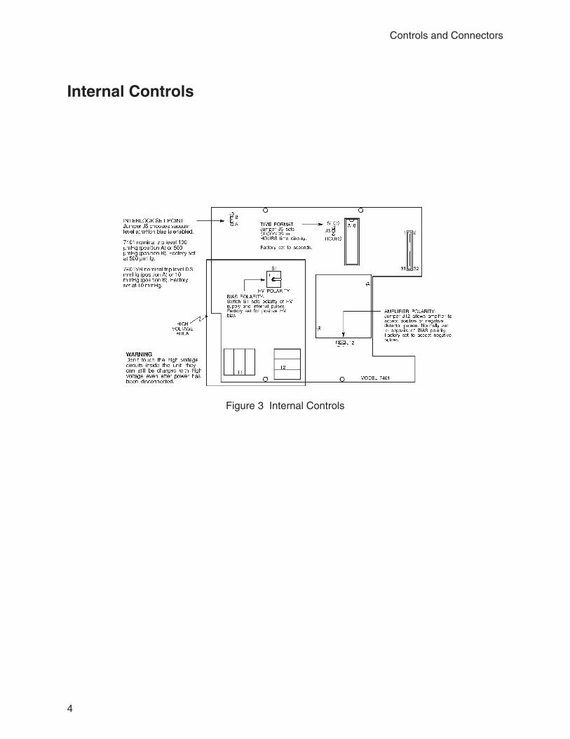
Figure 3 Internal Controls

Vacuum ChamberNote: For Reverse Sample Bias Kit installation, see drawing B-26491, which can be or-dered from Canberra.
5
Vacuum Chamber
Figure 4 Vacuum Chamber
3. Operating Instructions
The 7401’s internal jumpers are factory set for the most common applications, but mayhave to be changed for a specific need. If you are going to change any jumpers, do it be-fore installing the module in the NIM Bin. To change the jumpers, remove the unit’s left-side cover; refer to “Internal Controls” on page 4 for specific information on eachjumper.
WARNING Don’t touch the high voltage circuits inside the unit: they canstill have a high voltage charge, even though the unit’s poweris off.
Installing The ModuleThe 7401’s power is supplied by Canberra’s Model 2000 NIM Bin and Power Supply, orequivalent bin conforming to DOE/ER-00457T. The Bin power and the 7401’s BiasSwitch should be OFF before installing or removing the unit.
Slide the 7401 into the Bin, making sure that the cover on the right side of the unit isseated in the Bin’s top and bottom guide rails. After seating the unit firmly into the Bin’spower connector, turn the 7401’s front panel captive screws clockwise until finger tight.
The Model 7401 can be operated where the ambient air temperature is between 0 and 50°C (120 °F, maximum). Perforations in the top and bottom of the 7401 allow cooling airto circulate through the unit.
When the 7401 is rack mounted with other heat generating equipment, be sure to provideadequate clearance to allow for sufficient air flow through the perforations in the NIMBin’s top and bottom covers.
Installing The DetectorCAUTION Turn the BIAS On/Off Switch OFF before installing the detec-
tor. Do not turn it on until the unit is ready for operation.
6

NOTE The detector face must be kept clean and free of contamina-tion for proper performance. Please be sure that the plasticcover is in place when installing or removing the detector.Read the PIPS Detector Information in Appendix B before in-stalling the detectors.
Be sure the sample shelf is in place. It prevents any particles which may be ejected fromthe valve from hitting the detector. With the plastic cover still in place, install a detectorby screwing it into the connector at the top of the chamber. After the detector is screwedfirmly into the connector, remove the plastic cover. Be careful not to touch the detectorface.
Compared with ruggedized Canberra PIPS detectors, conventional SSB detectors may bevery sensitive to conditions causing microplasma breakdown. Be sure to read the detec-tor’s instruction sheet before installing and using the detector.
Connecting The PumpThe vacuum pump is connected to the Model 7401 vacuum fitting located on the rearpanel. The outside diameter of the fitting is 9.5 mm (3
8 in.). Use metal tubing and highquality rubber couplers wherever possible in the vacuum line to minimize outgassing andto ensure a short pumpdown time.
Connecting the MCAUsing 93 ohm cable (type RG-62), connect the ENERGY Output of the 7401 to the ADCinput of the multichannel analyzer. If multiple 7401 modules are being used, connecteach 7401 ENERGY Output to one of the Mixer/Router Inputs.
Preliminary SetupWith the detector installed and no sample in the chamber, close the door and set the 7401switches as follows.
Bias On/Off Switch OFF
Vacuum/Bias Interlock Switch ON
Turn on the 7401’s power by turning on the NIM Bin’s power switch.
7
Connecting The Pump

OperationCAUTION Do not turn on the BIAS Switch until the proper bias voltage
has been set. See Setting Bias the First Time on page 8.
Using the front panel switches you can select any of eight items for display. See Figure 5.Front panel switches also allow you to adjust settings, control the counter/timer and turnthe bias voltage on and off.
The INCrement/DECrement and DIGIT SELECT Switches are used to control the dis-play function and to change the 7401’s settings. To change the display function, firstmake sure that no single digits are blinking. If a single digit is blinking, press the DIGITSELECT Switch one or more times until all digits are steadily lit. Then use the INCre-ment/DECrement Switch to choose a different function. The selected function’s LED willturn on.
If all digits on the display are blinking at once, an overrange condition exists. In thiscase, the function can be changed using the INCrement/DECrement Switch.
Four instrument settings can be adjusted using the front panel controls: Preset Time (P-TIME), BIAS, DISCriminator Energy, and CALibration pulser energy.
8
Operating Instructions
Figure 5 Front Panel Switches
To adjust a parameter setting, first make sure that the corresponding LED is lit. Thenpress the DIGIT SELECT button until the digit that is to be changed blinks. Once thedigit is blinking, use the INCrement/DECrement Switch to change the setting.
To advance to the next digit, press the DIGIT SELECT switch again. Repeat this for asmany digits as necessary, then press the DIGIT SELECT button one or more times untilall digits are steadily lit. Note that either of two digits can be changed when adjustingBIAS voltage and DISCriminator and CALibration pulser energies. Any of five digitscan be changed in Preset Time (P-TIME).
The Model 7401’s internal memory maintains BIAS, DISCriminator and CALibrationpulser settings when the unit’s power is turned off. To insure proper memory operation,make sure that all changes to these settings have been completed before turning the7401’s power off.
If the BIAS Function is selected, the display always indicates the voltage applied to thedetector bias network. If the BIAS Switch is turned off, the bias will remain close to zerovolts. Once the BIAS Switch is turned on, the display will show the detector voltage as itincreases to the bias level stored in internal memory.
Initializing The DisplayThe front panel display is initialized to show the Bias whenever the unit’s power isturned off, then on. To aid in testing, it can also be reset and initialized by simultaneouslypressing the RESET and DIGIT SELECT push buttons while pressing the INC/DECSwitch to the INC position. When the unit is reset, the stored BIAS, DISCriminator, andCALibrate settings will not be changed.
Applying VacuumApplying the vacuum is done in three steps:
1. Set the display to read VACuum.
2. Start the vacuum pump.
3. Pull the valve handle out to the PUMP position and rotate the handle 14-turn
counterclockwise (Figure 6). The gurgling sound should stop in a minute or soif there are no leaks in the vacuum line.
9
Initializing The Display

Setting Bias the First TimeThroughout this operation the display, which is monitoring the voltage applied to the de-tector bias network, will show a voltage close to zero.
CAUTION The high voltage memory should be reset to zero before turn-ing on the BIAS Switch for the first time, or when changingdetectors.
1. Use the INC/DEC Switch to select the BIAS Function; its LED is lit when thefunction is selected. Now press the DIGIT SELECT pushbutton twice to selectthe bias voltage tens digit; that digit will blink when it is selected.
With the tens digit selected, the bias voltage will change by 10 volts each timethe INC/DEC Switch is pressed. Press the INC/DEC Switch to the DECrementposition 20 times to insure that the voltage setting stored in the internal memoryhas been reset to zero (0). The display will show a voltage close to zero since itis monitoring the detector bias network.
2. After the high voltage has been reset to approximately zero volts, turn the BIASSwitch on.
CAUTION Avoid applying excess voltage to the detector. Wait approxi-mately one minute after turning on the BIAS Switch (until theBIAS on/off LED stops blinking) before increasing the volt-age. This will allow time for the bias voltage to stabilize.
3. Starting with the bias at approximately zero, slowly increment the bias to therecommended voltage while monitoring the voltage display. Refer to theDetector Instruction Sheet for the method used in applying bias to a newdetector. When a low leakage detector is being used, it is not necessary tocorrect for the voltage drop in the bias network.
10
Operating Instructions
Figure 6 Valve Operation

Once the correct bias has been set, it will automatically be applied with a time constant ofapproximately one minute when the BIAS Switch is turned on and the vacuum conditionsare correct. The bias should always be turned OFF manually before the chamber isvented and the door is opened. The BIAS Switch should be turned ON manually only af-ter the door has been closed and the pump-down has started.
Previous Bias SettingIf the bias has been previously set to the correct voltage, power can be applied to the de-tector by selecting the BIAS Function and turning on the front panel BIAS Switch. If therear panel VACUUM/BIAS INTERLOCK Switch is on, bias will not be applied untilvacuum reaches the internally preset level. This may take a few minutes and it is depend-ent on the size and type of vacuum pump and vacuum tubing.
Sample PlacementBefore opening the door make sure that the high voltage to the detector has been turnedoff. Then after pressing the chamber valve to VENT the chamber, open the door and setthe shelf height as desired. See Figure 4. Note that the scale on the left side of the plasticshelf holder can be used as a reference in positioning the holder. Insert the sample holdertray holding the sample.
When the sample is in place, close the door, pull the chamber valve to the PUMP posi-tion and lock it by rotating the handle 1
4-turn counter clockwise (Figure 6).
After the chamber is pumped down and the Bias voltage has stabilized, data collectionmay be started.
At the end of the experiment, set the BIAS Switch to off, vent the chamber and open thedoor to remove or replace the sample.
System CalibrationTo calibrate the system, insert a known source in the chamber, accumulate a spectrumand use the 7401 gain control to position the isotope peak at the desired MCA channel.Adjustment of the ADC Gain, Range and Digital Offset controls may also be necessary,as well as the ADC Zero.
11
Previous Bias Setting

The 7401 amplifier offset is factory set to zero volts, but may be adjusted to ±200 mV.The amplifier output pulses and offset may be monitored at the front panel TEST POINTusing an oscilloscope.
Calibration may also be accomplished using the 7401’s Calibration Pulser. To use thepulser first select the CAL Function. Then set the desired energy and turn on the pulserby pressing the START/STOP Switch to the START position. The CAL LED will blink.Adjust the gain control to place the pulser peak at the desired channel of the MCA spec-trum. The Calibration Pulser will turn itself off when you leave the CAL Function.
Using the Discriminator Counter/TimerTo use the counter/timer, first determine the lowest energy alpha particles which are to becounted. Then use the front panel controls to display the discriminator level and set theDiscriminator to the required energy. Next set the Preset Time by moving to the PresetTime Function (P-TIME) and entering the appropriate setting. Once this is done, turn thecounter on by pressing the START/STOP Switch to START. The counter/timer can bestarted, stopped and reset using the front panel switches, but only when one of the threecounter/timer functions is selected: Preset Time (P-TIME), Elapsed Time (E-TIME), orCOUNTS.
If Preset Time is set to zero, the counter will continue to count indefinitely. When theElapsed Time timer has counted beyond 99 999 seconds it will “roll over” to 0 and con-tinue counting; the entire display will blink to indicate that rollover has occurred. Thegross alpha counter will not advance beyond 99 999.
The time readout is factory set to display seconds, but an alternate display in hours andhundredths of hours (HHH.HH) can be chosen by moving an internal jumper (refer to“Internal Controls” on page 4 ) and either turning the power off then on, or by using thefront panel switches to initialize the display (see “Initializing the Display” on page 9).
The COUNTS output on the rear panel is available to drive an external counter with thediscriminator output.
Multiple 7401s On a Single PumpA single vacuum pump can be connected to more than one 7401, however the pumpdown time may increase. To connect more than one unit to the vacuum pump, you mustinstall a fitting or manifold system to expand the number of vacuum lines.
12
Operating Instructions
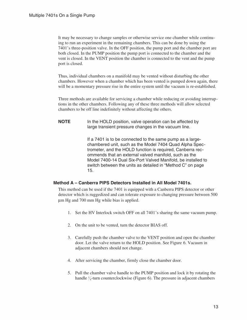
It may be necessary to change samples or otherwise service one chamber while continu-ing to run an experiment in the remaining chambers. This can be done by using the7401’s three-position valve. In the OFF position, the pump port and the chamber port areboth closed. In the PUMP position the pump port is connected to the chamber and thevent is closed. In the VENT position the chamber is connected to the vent and the pumpport is closed.
Thus, individual chambers on a manifold may be vented without disturbing the otherchambers. However when a chamber which has been vented is pumped down again, therewill be a momentary pressure rise in the entire system until the vacuum is re-established.
Three methods are available for servicing a chamber while reducing or avoiding interrup-tions in the other chambers. Following any of these three methods will allow selectedchambers to be off line indefinitely without affecting the others.
NOTE In the HOLD position, valve operation can be affected bylarge transient pressure changes in the vacuum line.
If a 7401 is to be connected to the same pump as a large-chambered unit, such as the Model 7404 Quad Alpha Spec-trometer, and the HOLD function is required, Canberra rec-ommends that an external valved manifold, such as theModel 7400-14 Dual Six-Port Valved Manifold, be installed toswitch between the units as detailed in “Method C” on page15.
Method A – Canberra PIPS Detectors Installed in All Model 7401s.This method can be used if the 7401 is equipped with a Canberra PIPS detector or otherdetector which is ruggedized and can tolerate exposure to changing pressure between 500µm Hg and 700 mm Hg while bias is applied.
1. Set the HV Interlock switch OFF on all 7401’s sharing the same vacuum pump.
2. On the unit to be vented, turn the detector BIAS off.
3. Carefully push the chamber valve to the VENT position and open the chamberdoor. Let the valve return to the HOLD position. See Figure 6. Vacuum inadjacent chambers should not change.
4. After servicing the chamber, firmly close the chamber door.
5. Pull the chamber valve handle to the PUMP position and lock it by rotating thehandle 1
4-turn counterclockwise (Figure 6). The pressure in adjacent chambers
13
Multiple 7401s On a Single Pump

will momentarily rise, then decrease as the pump removes the air introducedfrom the serviced chamber.
Method B – Other Detector Types Installed, such as Standard SSB Detectors,.This method should be used when any of the 7401’s are equipped with a detector whichmight be damaged by exposure to changing pressure between 500 µm Hg and 700 mmHg while bias is applied.
An additional step has been included here to isolate the chambers which are not servicedfrom any momentary loss of vacuum.
1. Remove the 7401’s side covers and verify that jumper J5, Interlock Set Point, isset to the 500 µm Hg position (position B). Refer to Figure 6 for the jumper’slocation.
2. Make sure that the VACUUM/BIAS INTERLOCK is enabled on all units.
3. On the unit to be vented, turn the detector BIAS off.
4. Carefully push the chamber valve to the VENT position (Figure 6) and open thechamber door. Let the valve return to the HOLD position. Vacuum in adjacentchambers should not change.
5. After servicing the chamber, firmly close the chamber door.
6. Place the valves on adjacent chambers in the HOLD position.
7. Pull the valve for the chamber which was serviced to the PUMP position andturn on the BIAS Switch. Bias will automatically be applied to the detectorwhen the correct vacuum is reached.
8. When the serviced 7401 chamber attains a vacuum similar to the adjacentchambers, carefully change the valves on the adjacent chambers to the PUMPposition.
The loss rate of the chambers on hold is typically 40 to 80 µm Hg per minute. This al-lows in excess of four minutes to evacuate the vented chamber before the 500 µm Hgvacuum trip point is reached on adjacent chambers. This is more than adequate time torepump the vented chamber.
14
Operating Instructions

Method C – Using the 7401 with the Model 7400-14 Dual Manifold,The Model 7400-14 is a Dual Six-Port Valved Manifold for use with vacuum chambersor Alpha Spectrometers. The 7400-14 makes it possible to service individual chamberswithout affecting the pressure in other chambers attached to the same pumping system.
The 7400-14 requires one vacuum pump, such as the Model 7400-01 or 7400-02, foreach of the unit’s two manifolds. The manifolds are connected to the vacuum chambersby means of three-way valves. In this way, the high vacuum manifold can remain at con-stant pressure while the pump-down manifold experiences the pressure transients associ-ated with pump-down of chambers.
An installation diagram, drawing B-201083, is available from Canberra. Note that two7400-11 Installation Kits and two 7400-09 Filters are required in addition to the twoModel 7400-01 or 7400-02 vacuum pumps.
Keep the length of hose between manifold and vacuum chambers as short as possible.
When a system is first assembled and tested it is important to get the vacuum system op-erating properly before detectors are installed in the vacuum chambers.
1. Seal all manifold ports not being used with the black rubber caps that areprovided with the 7400-14.
2. Evacuate the lines and observe pump behavior with all valves in the offposition. If the pump’s gurgling sound continues after more than a few minutesof operation, it indicates a gross leak.
3. Change one valve to the pump-down position and note that the pressure in theassociated spectrometer begins to decrease after a few minutes of pumping. Itwill take several minutes for the pressure to reach the 1000 µm Hg read-outlimit of standard Canberra Spectrometers. When the pressure reaches about 100µm Hg you will know that this channel and the pump-down manifold are freeof gross leaks. Turn the valve to the High-Vacuum position and verify that thepressure on this side is in the same range.
4. If the pressure on either side is not in the right range tighten and or re-lubricatethe vacuum line couplings.
5. Repeat step 3 for each of the spectrometers in the system.
Routine Operation of the 7400-141. Always evacuate chambers with the valve in the Pump-Down position.
15
Multiple 7401s On a Single Pump

2. When the pressure in the chamber reaches the normal operating range turn thevalve to the High Vacuum position.
3. Before opening a chamber turn the associated manifold valve to the pump-down position.
4. Before re-evacuating a chamber check to see that the associated manifold valveis in the pump-down position.
Routine Precautions1. Never connect an evacuated chamber to a manifold or pump which is not under
vacuum. The chamber may draw oil vapor from the pumping system andcontaminate detectors.
2. Service vacuum pumps periodically. Do not wait for them to fail. Consultmanufacturer’s instructions.
3. Replace filters periodically. Oil clogged filters will reduce pumping speed andmay allow backstreaming.
16
Operating Instructions
4. Circuit Description
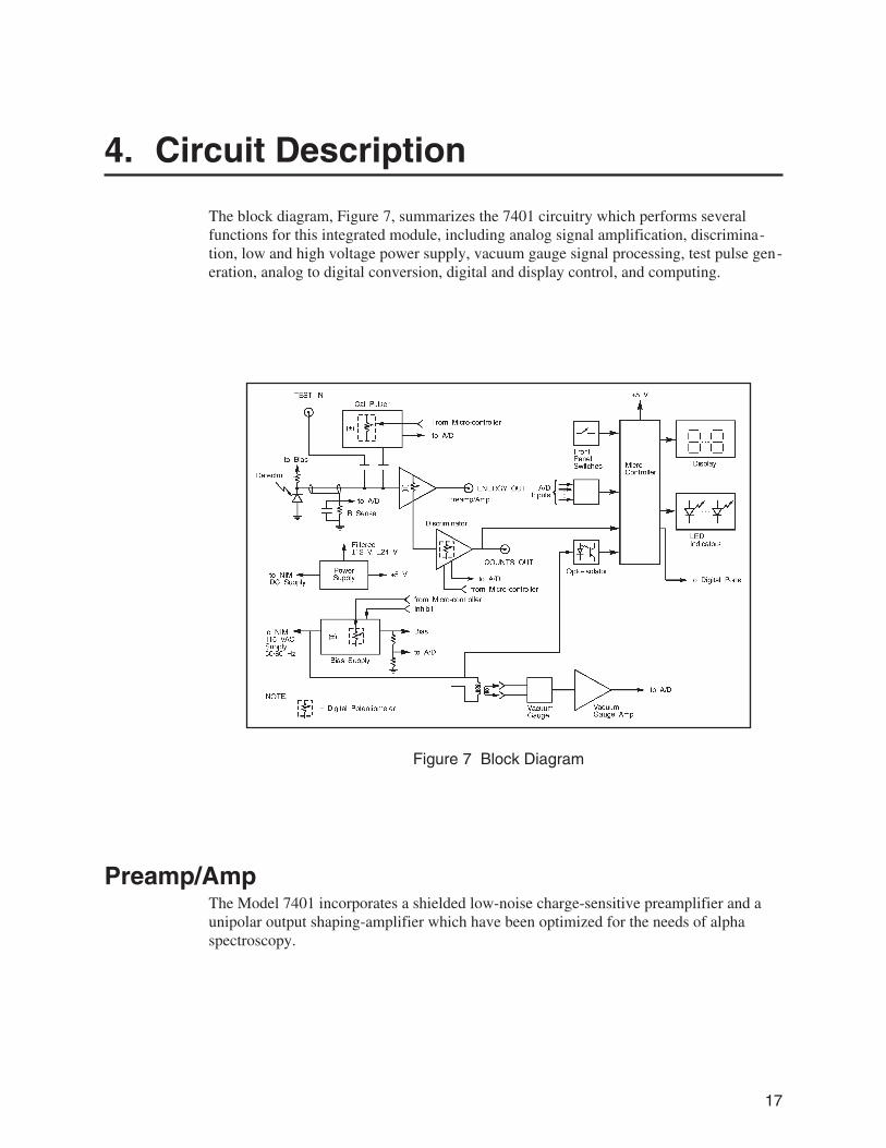
The block diagram, Figure 7, summarizes the 7401 circuitry which performs severalfunctions for this integrated module, including analog signal amplification, discrimina-tion, low and high voltage power supply, vacuum gauge signal processing, test pulse gen-eration, analog to digital conversion, digital and display control, and computing.
Preamp/AmpThe Model 7401 incorporates a shielded low-noise charge-sensitive preamplifier and aunipolar output shaping-amplifier which have been optimized for the needs of alphaspectroscopy.
17
Figure 7 Block Diagram

The preamplifier consists of input FET Q14, differential amplifier Q12 and Q11, outputfollower FET Q13 and current sinks Q20 and Q19. This group of devices functions as aninverting feedback amplifier whose closed-loop gain is set by the charge-integrating ca-pacitor C122. Internal bias-currents for FET Q14, loop gain, and compensation are set toprovide best performance for the large area, thin detectors most commonly employed forlow-level alpha particle counting. Bias stabilization is provided by the dc feedback paththrough R15. This component serves to discharge C122 following each charge integra-tion, and sets the tail-pulse shape of the preamplifier at a nominal 470 µs decay time con-stant. Diode D1 provides protection for Q14 from the transient voltages experienced frommomentary breakdowns in the detector bias circuit due to accidental faults.
The calibration pulser input includes potentiometer RV10 which is factory set so that theoutput pulse amplitude represents the energy displayed in MeV. Thus you can pre-calibrate a region of interest without having to use an open source.
Detector current is filtered by C39, C301, C302, R1 and C38, then sensed by R191 whichgenerates a voltage that is measured by the A/D. The result is displayed when LEAKageFunction has been selected by the front panel controls.
Following the charge integrator is a pole/zero compensated differentiator (C6, R20 andR21) set for a nominal 0.5 µs decay time constant. The time-clipped tail pulse is ampli-fied by a fixed gain non-inverting feedback amplifier formed by differential pair Q17 andQ25, driver Q18 and push-pull outputs Q16 and Q15. The gain of this amplifier stage isfixed at X30.
Preliminary integration is provided by R30, L2, and C21 before the signal is fed to thesplit-load inverter Q21, which permits polarity selection by the internal jumper plug J12.Q22 buffers the signal before the second integration in R39, L3 and C24. The filteredsignal is then amplified again by A25, which incorporates the front-panel-mounted gaincontrol in its feedback path. The signal is a positive-going pulse at this point, and D4 lim-its the excursion by clamping the output of A25 to enhance prompt overload recovery.
Capacitor C120 couples the positive pulse into the simple restorer provided by Q23. Thiscircuit stabilizes the dc reference level for the pulse in order to maintain a proper baselinefrom which the output may be quantized in an ADC or SCA.
Output amplifier A26 provides the final stage of gain and permits the introduction of a dcoffset/zero-adjust, controlled by a front panel potentiometer. D5 limits the positive excur-sion to prevent saturation in either A26 or output transistor Q24 and insures prompt over-load recovery.
The output is a unipolar semi-Gaussian pulse with a shaping time constant of 0.5 µs. Thisintegration has been found to be nearly optimum for the noise spectrum of typical surfacebarrier alpha particle detectors to provide the best energy resolution.
18
Circuit Description
Auxiliary CircuitsThe auxiliary circuits include the power supplies for the detectors and preamp/amp, thethermocouple vacuum gauge circuitry, the calibration pulser, discriminator and A/D. Ascan be seen on the schematic, interlocking, switching, and sensing is necessary for theproper integration of these subsections.
Power SuppliesThe internal 12 V and 5 V supplies are derived from inductor-capacitor filters, three-terminal regulators and Zener diode regulators. The detector high voltage bias is derivedfrom the 115 V ac supplied by the NIM power supply which is boosted by transformerT1 then full-wave rectified, filtered by capacitor C3, and controlled by a discrete compo-nent series regulator. The output polarity is selected by a board-mounted toggle switch(S1). The reference voltage is derived from D6 as adjusted by digital pot A5.
When the VACUUM/BIAS INTERLOCK is enabled by the rear panel switch, a time-delay interlock keeps the detector bias regulator cut off until satisfactory chamber vac-uum is detected by comparator A1. When this occurs A1 pin 1 goes low, and Q5 turns offto remove the short across D6. Upon activation of the high voltage section, C38 ischarged through R61 until Q4 and Q6 permit D6 to achieve its full Zener voltage. As reg-ulator diode D6 approaches its full voltage, sense transistor Q1 turns on, sending a signalto the microprocessor. This delay and exponential rise permit detector bias to be appliedslowly at a controlled rate to prevent detector damage due to surface breakdown.
Amplifier A4 and high voltage transistors Q2 and Q3 provide high voltage regulation.Closed loop dc gain is determined by the ratio of R67 to R66. When set for a positiveoutput voltage, the input at pin 2 of A4 is amplified and output is controlled by Q2 actingas a shunt element and Q3 acting in series between the high voltage and the load.
Vacuum GaugeThe thermocouple vacuum gauge is biased from a controlled ac current source derivedfrom the back-to-back Zener diodes D17 and D18, and through RV15 into a currenttransformer. The gauge output is a dc voltage representing the temperature of a thermallyisolated heater wire as influenced by static air pressure (or vacuum) in the chamber. Am-plifier A2 boosts the low level DC signal and sends it to comparator A1 and to the A/Dfor digitizing and subsequent linearization by the microprocessor.
19
Auxiliary Circuits

The calibration for vacuum gauge circuitry is performed during assembly and test so thata reasonable indication of vacuum may be monitored by A1. The detector bias-circuit canbe enabled when the chamber reaches the preset vacuum level selected by J5. The 7401’spreset level can be either 100 or 500 µm Hg. The 7401VR’s preset level can be either 0.3or 10 mm Hg. RV1 and RV2 adjust the thresholds.
Calibration PulserThe reference voltage for the calibrated pulser is derived from Zener diodes D15 or D16,as selected by switches S1 and A9. Digital potentiometer A10 feeds a selected dc voltagelevel to switch A13 to charge capacitor C119. The dc level is also divided through R91and R92 to provide a voltage for the front panel digital display. Oscillator A11 controlsthe repetition rate of the pulse generator. The charge on C119 is switched by A13 toshaping components C61 to control rise time, and R170 to control decay time before be-ing fed to the calibration pulser input of the preamp/amp.
DiscriminatorThe reference voltage for the discriminator is derived from Zener diode D28. Digital po-tentiometer A22 feeds a selected dc voltage level through divider R57-R56-RV13 to theA/D for display and to one input of comparator A24. Amplifier A23 samples the shapedalpha pulse and supplies the other input to comparator A24. RV20 and RV12 allow ad-justment of discriminator offset and gain. The output of the comparator is fed to one-shotA14 and then via buffer A17 to the rear panel BNC COUNTS output. The output of thediscriminator one-shot is also connected to the microprocessor’s internal counter.
Analog to Digital ConverterThe A/D can measure one of eight different dc inputs. Three of the inputs, +12 V, –12 V,and 0 V, available at analog multiplexer A8, are test inputs. The other five inputs arevoltages coming from the auxiliary circuits for display. The output of the multiplexer isfiltered by R123 and C69 and fed to A/D converter A7, whose output appears on the mi-croprocessor data bus.
Microprocessor and Control CircuitsThe microprocessor controls the front panel switch and display functions, the coun-ter/timer and the three digital pots. It also reads the internal A/D converter, scaling andlinearizing the data for display.
20
Circuit Description

The processor sends display information to display driver A21, whose power supply isregulated by shunt regulator D32. This regulator prevents excessive low frequency ripplefrom appearing on the power supply lines. Front panel switch status is passed to the mi-croprocessor by buffer A19.
By reading the power line frequency through opto-isolator A6, the processor establishesan accurate 1 second time base for the counter/timer. If the power line frequency is notwithin the 50 or 60 Hz specification, the processor uses an internal crystal-controlledcounter to generate the time base.
Digital pots A5, A10, and A22 are each controlled by the microprocessor through threecontrol lines. Each digital pot has 100 discrete settings and retains its last setting in inter-nal memory when power is removed.
In order to allow for processor reset without cycling the power, three front panel switchesare connected to inverters in package A17, which sends a reset pulse to the microproces-sor.
21
Microprocessor and Control Circuits

A. Specifications
InputTEST INPUT - Accepts signal from external pulser; Zin = 93 Ω; gain nominally X 10;rear panel BNC.
OutputsENERGY OUTPUT - Provides positive, linear near-Gaussian shaped unipolar pulsesproportional to energy, linear to + 10 V; max output 12 V; dc restored; Zout = 10 Ω; shortcircuit protected; rear panel BNC.
TP (Test Point) - Replica of the energy output signal; isolated by 1 kΩ resistance; frontpanel mounted pin jack.
COUNTS OUTPUT - NIM-standard positive logic pulse available on rear panel BNCconnector for driving external counter; pulse width nominally 3.5 µs for any event abovediscriminator setting; Zout ≈ 50 Ω, dc coupled.
DisplayMulti-purpose 5-digit LED display shows chamber pressure in µm Hg (mm Hg on the7401VR), detector leakage current (µA), gross counts, elapsed time, preset time, highvoltage bias, discriminator level (MeV), and calibration pulser level (MeV); time readoutin seconds or hours.
Front Panel Controls and IndicatorsBIAS ON/OFF - Toggle switch controls high voltage supply
BIAS LED Indicator - Blinks when high voltage is inhibited and while supply is increas-ing to preset value; solidly illuminated when supply approaches final value.
FUNCTION LED Indicators - One of eight LEDs is illuminated when correspondingfunction is selected for display; COUNTS LED blinks when counter is active; CAL LEDblinks when calibration pulser is active.
22

INCREMENT/DECREMENT - Dual purpose momentary toggle switch selects displayfunction and sets preset time, HV bias, calibration pulser level or discriminator level.
DIGIT SELECT - Pushbutton switch chooses display digit to be incremented or decre-mented; operable when setting preset time, HV bias, calibration pulser, or discriminatorlevel.
START/STOP - Dual purpose momentary toggle switch starts or stops counter whencounter functions are selected or starts/stops pulser when calibration pulser is selected.
RESET - Pushbutton resets counter and timer.
GAIN - Screwdriver adjustable multi-turn potentiometer adjusts amplifier gain.
OFFSET - Screwdriver adjustable multi-turn potentiometer adjusts amplifier offset.
PUMP/OFF/VENT - 3-position valve control; PUMP connects vacuum pump to cham-ber; OFF isolates pump from chamber and chamber from atmosphere; VENT ventschamber to atmosphere and isolates pump. Locks in pump position by turning handle onequarter turn counterclockwise.
Rear Panel ControlVACUUM/BIAS INTERLOCK - Locking toggle switch enables or disables HV inhibit;inhibit is triggered when chamber pressure exceeds threshold.
Internal ControlsVACUUM/BIAS INTERLOCK SET POINT - Dual position jumper chooses vacuumlevel at which bias is enabled. 7401 nominal trip level is 100 or 500 µm Hg (13 or 67Pa); factory set to 500 µm Hg (67 Pa). 7401VR nominal trip level is 0.3 mm Hg (0.04kPa) or 10 mm Hg (1.33 kPa); factory set to 10 mm Hg (1.33 kPa).
BIAS POLARITY - Toggle switch sets polarity of HV supply and internal pulser. Fac-tory set for positive HV bias.
AMPLIFIER POLARITY - Jumper allows amplifier to accept positive or negative detec-tor pulses. Factory set to process negative pulses.
23
Rear Panel Control
TIME FORMAT - Jumper sets seconds or hours time display. Factory set for secondsdisplay.
System Performance(Based on use of a 450-20 AM PIPS detector with a good quality 241Am point source.)
Energy Resolution
≤20 keV (FWHM) with a detector-source spacing equal to the detector diameter.
Detector Efficiency
≥25% for detector-source spacing of less than 10 mm.
Background
≤1 count/hr above 3 MeV.
Electronics PerformanceOPERATING TEMPERATURE RANGE - 0 to 50 °C.
BIAS SUPPLY
Range - Nominal 1 V to ±198 V dc, adjustable in 2 V steps from 2 V to full voltage.
Stability - Better than 50 ppm/°C.
Noise - ≤5 mV peak-to-peak.
Display Resolution - 0.1 V.
CALIBRATION PULSER
Range - 0.1 to 10 MeV, adjustable in 0.1 MeV steps.
Stability - Better than 50 ppm/°C.
Display Resolution - 10 keV
24
Specifications

DISCRIMINATOR
Range - 0.1 to 10 MeV
Display Resolution - 10 keV
DETECTOR CURRENT MONITOR
Range - 0 to 20.00 µA
Display Resolution - 0.01 µA
VACUUM GAUGE
7401 Range - 0 to 1000 µm Hg (0 to 133 Pa)
7401VR Range - 0 to 20 mm Hg (0 to 2.67 kPa)
COUNTER
Count Range - 0 to 99 999 counts.
Time Range - 0 to 99 999 seconds or 0 to 999.99 hours.
Preset Time Range - Same as Time Range.
Time base - 50 Hz or 60 Hz power line frequency or internal crystal, automaticallyselected.
PREAMPLIFIER/AMPLIFIER
Shaping - 0.5 µs unipolar, dc restored.
Integral Nonlinearity - ≤0.4% of full scale.
Gain Range - 6 MeV to 13 MeV full scale (17 to 40 V/pC, 1 to 2.5 V/MeV).
Gain Drift - ≤200 ppm/°C
DC Drift - ≤±100 µV/°C
25
Electronics Performance

Noise - ≤0.12 fC RMS referred to input at 0 pF input capacitance.
Offset range - 0 to ±200 mV
ConnectorsTEST INPUT, ENERGY OUTPUT and COUNTS OUTPUT - BNC type UG-1094/U.
VACUUM - 9.5 mm (38 in.) O.D. aluminum fitting mounted through rear panel.
DETECTOR - Axial microdot
Power Requirements+12 V dc – 250 mA +24 V dc – 100 mA
–12 V dc – 50 mA –24 V dc – 50 mA
PhysicalSIZE - Standard double-width NIM module 6.86 X 22.12 cm (2.70 X 8.71 in.) perDOE/ER - 0457 (1990).
NET WEIGHT - 2.5 kg (5.5 lb)
SHIPPING WEIGHT - 3.2 kg (7.0 lb)
VACUUM CHAMBER AND HARDWARE - 8.16 X 6.03 X 6.25 cm (3.25 X 2.375 X2.5 in.) (height, width, depth). Stainless steel chamber, door, shelf and sample holder.
SAMPLE SIZE - Up to 51 mm (2 in.) diameter
MAXIMUM DETECTOR SIZE - 1200 mm2
SAMPLE-DETECTOR SPACING - 1 to 49 mm in 4 mm steps
26
Specifications

SAMPLE HOLDER - One Model 7401SH-4 sample holder for 25 mm (1 in.) samples issupplied. Other sample holder sizes are available as extra cost options.
EnvironmentalOPERATING TEMPERATURE – 0 to 50 °C.
RELATIVE HUMIDITY – Up to 80%, non-condensing.
Tested to the environmental conditions specified by EN 61010, Installation Category I,Pollution Degree 2.
OptionsMODEL 7401-RSB Reverse Sample Bias - Includes four 3 V batteries mounted on thesample shelf. The average battery life is 8 years.
MODEL 7401VR Alpha Spectrometer - Same as 7401 except the pressure gauge has arange of 0 to 20 mm Hg (0 to 2.67 kPa); also includes Model 7401-RSB Reverse SampleBias option.
Model 7401SH-3 sample holder for 19 mm (34 in.) samples.
Model 7401SH-8 sample holder for 51 mm (2 in.) samples.
27
Environmental

B. PIPS Detector Information
HandlingThe PIPS detector should be handled with care. The implanted face contact, while not asfragile as an evaporated gold contact, is nonetheless very thin, as it must be in order toachieve high efficiency and good resolution for alpha particles. Do not touch the surfacewith anything that might cause scratches or abrasion.
OperationThe PIPS detector has implanted, passivated contacts which are protected from the envi-ronment so there is little risk of microplasma breakdown upon application of bias. How-ever, if the detector has been stored in humid conditions, it should be kept in vacuum fora short while to remove excess condensation before applying bias.
Alpha resolution is measured using a point source at least one detector diameter awayfrom the detector face. Resolution will not be as good with the source closer because ofthe more acute angle of particle travel through the entrance window.
Alpha sources do not emit monoenergetic alphas, but have an intrinsic line width thatcontributes to system resolution. Our detectors are tested using good quality sources,such as the NBS 4904G. The use of old or inferior calibration sources may cause resolu-tion problems and can lead to detector contamination due to recoil sputtering.
CleaningThe PIPS detector can be cleaned with a cotton ball dampened with a good grade of ace-tone. Avoid excess wetting of the detector assembly, but repeat the cleaning treatmentwith fresh cotton to eliminate traces of contamination. Blow dry with dry air or dry nitro-gen gas and vacuum pump for 15 minutes or so to remove residual moisture before ap-plying bias.
28

C. Power-On Error Codes
When the 7401 is turned on or reset from the front panel (“Initializing the Display” onpage 9), the microprocessor runs several tests. If an error is detected one of the followingerror codes will be displayed:
E1 RAM test error. RAM is on board the micro-processor.
E2 Checksum error for program code in EPROM on board the microprocessor.
E3 A/D error. No change in A/D status line within a 100 ms time period.
E4 The ac power line was not detected by the module. Module will use internaltimer as time base.
E5 The ac power line was detected by the module but the line frequency is notwithin ± 0.5 Hz of 50 or 60 Hz. Module will use internal timer as time base.
29

D. Self Tests
CAUTION Avoid detector damage by removing it from the chamber be-fore executing any of the high voltage tests.
The 7401 will execute several internal tests when in the test mode, which is enabled byresetting the module. This is done by cycling power or using the front panel resetswitches (“Initializing the Display” on page 9). Immediately after the reset, press theRESET and DIGIT SELECT buttons simultaneously and hold the switches until the soft-ware revision level is displayed. Then the numeral “1” will be displayed signifying thatthe unit is ready to perform test number one. Use the INC/DEC switch to choose a test.
Press the START switch to start the test. The letter “P” will be displayed if the test waspassed. The letter “E” indicates an error. After each test is finished, the program returnsto the select mode.
NOTE When the self-tests are executed, the digital pot settings forBias, Calibration pulse level, and Discriminator level will bealtered.
After completing the self-tests, resume normal operation by cycling power or using thefront panel switches to reset the unit (see “Initializing the Display” on page 9).
Switch Test (Test 1)This tests all front panel switches. After the START switch is pressed, the number 1.0will be displayed, meaning press the START switch (again). If the test is passed, thenumber will increment and the test will wait for the next switch to be pressed.
1.0 – Press the START switch (again).
1.1 – Press the STOP switch.
1.2 – Press the RESET switch.
1.3 – Press the INCREMENT switch.
1.4 – Press the DECREMENT switch.
1.5 – Press the DIGIT SELECT switch.
30

After the DIGIT SELECT test passes, the program returns to the select mode.
Display Test (Test 2)When this test is selected and START switch is pressed, 2.0 is displayed. The displaythen cycles through the display characters and tests the LED indicators. After that theprogram returns to select mode.
A/D Test (Test 3)This tests the A/D integrated circuit. If error indicator “E” is displayed, the STARTswitch must be pressed to continue.
E 3.0 – Failure when measuring +12 V.
E 3.1 – Failure when measuring –12 V.
E 3.2 – Failure when measuring 0.0 V.
HV Bias Test (Test 4)Remove the detector before executing this test, which tests the high voltage bias supplyand digital pot. If an error is encountered, START switch must be pressed to continue.
Before starting this test, turn on the bias voltage. If the test is begun with the bias off, thebias on/off LED will blink, reminding you to turn on the bias. It takes about a minute tostabilize the high voltage.
E 4.0 – Pot cannot be set to lowest setting.
E 4.1 – Pot fails mid-point check.
E 4.2 – Pot fails high setting check.
E 4.3 – Pot fails step-size check.
After completing the Bias test, turn off the bias switch.
31
Display Test (Test 2)

Calibration Pulser Pot Test (Test 5)Tests calibration pulser digital pot. If an error is encountered, START switch must bepressed to continue. This test is a long one, please wait for it to finish.
E 5.0 – Pot cannot be set to lowest setting.
E 5.1 – Pot fails mid-point check.
E 5.2 – Pot fails high setting check.
E 5.3 – Pot fails step-size check.
Discriminator Digital Pot Test (Test 6)Tests discriminator digital pot. If an error is encountered, START switch must be pressedto continue.
E 6.0 – Pot cannot be set to lowest setting.
E 6.1 – Pot fails mid-point check.
E 6.2 – Pot fails high setting check.
E 6.3 – Pot fails step-size check.
Pulser/Amp/Discriminator Test (Test 7)Checks that test pulser, amplifier and discriminator are calibrated and work correctly as asystem.
E 7.0 – No counts detected with discriminator level below pulser level.
E 7.1 – Erroneous counts detected with discriminator level above pulser level.
32
Self Tests
E. Chamber Cleaning
Before cleaning the chamber, you should remove the detector and the plastic shelf holderinsert. To remove the plastic insert, unscrew the nut at the bottom of the chamber using a13 mm (1
2 in.) wrench. When reinstalling the plastic insert, remember that the nutholding the insert also provides the force necessary to seal the valve to the chamber. Thenut should be tightened firmly. Since the vacuum is drawn through the bushing at thebottom of the can, be careful to avoid contaminating the vacuum path. Plug the hole ifnecessary. Also avoid introducing cleaners into the vacuum gauge mounted at the top ofthe chamber.
If the large detector mounting bushing is removed for any reason or if the detectorBNC/Microdot connector is removed from the bushing, care must be taken when re-threading the plastic parts. Care must also be exercised when removing and replacing therubber gaskets and O-rings. A sharp tool can damage the rubber parts. Nitrile (Buna N)and flourocarbon rubbers are used for the gaskets. If a gasket has been wiped clean,smooth on a light coat of silicone vacuum grease with the fingers before reassembling.
33

F. Installation Considerations
This unit complies with all applicable European Union requirements.
Compliance testing was performed with application configurations commonly used forthis module; i.e. a CE compliant NIM Bin and Power Supply with additional CE compli-ant application-specific NIM were racked in a floor cabinet to support the module undertest.
During the design and assembly of the module, reasonable precautions were taken by themanufacturer to minimize the effects of RFI and EMC on the system. However, careshould be taken to maintain full compliance. These considerations include:
• A rack or tabletop enclosure fully closed on all sides with rear door access
• Single point external cable access
• Blank panels to cover open front panel Bin area
• Compliant grounding and safety precautions for any internal power distribution
• The use of CE compliant accessories such as fans, UPS, etc.
Any repairs or maintenance should be performed by a qualified Canberra servicerepresentative. Failure to use exact replacement components, or failure to reassemble theunit as delivered, may affect the unit’s compliance with the specified EU requirements.
34

Canberra (we, us, our) warrants to the customer (you, your) that for a period of ninety (90) days from the date ofshipment, software provided by us in connection with equipment manufactured by us shall operate in accordance withapplicable specifications when used with equipment manufactured by us and that the media on which the software isprovided shall be free from defects. We also warrant that (A) equipment manufactured by us shall be free from defectsin materials and workmanship for a period of one (1) year from the date of shipment of such equipment, and (B)services performed by us in connection with such equipment, such as site supervision and installation servicesrelating to the equipment, shall be free from defects for a period of one (1) year from the date of performance of suchservices.
If defects in materials or workmanship are discovered within the applicable warranty period as set forth above, weshall, at our option and cost, (A) in the case of defective software or equipment, either repair or replace the software orequipment, or (B) in the case of defective services, reperform such services.
LIMITATIONSEXCEPT AS SET FORTH HEREIN, NO OTHER WARRANTIES OR REMEDIES, WHETHER STATUTORY,WRITTEN, ORAL, EXPRESSED, IMPLIED (INCLUDING WITHOUT LIMITATION, THE WARRANTIES OFMERCHANTABILITY OR FITNESS FOR A PARTICULAR PURPOSE) OR OTHERWISE, SHALL APPLY. IN NOEVENT SHALL CANBERRA HAVE ANY LIABILITY FOR ANY SPECIAL, EXEMPLARY, PUNITIVE, INDIRECT ORCONSEQUENTIAL LOSSES OR DAMAGES OF ANY NATURE WHATSOEVER, WHETHER AS A RESULT OFBREACH OF CONTRACT, TORT LIABILITY (INCLUDING NEGLIGENCE), STRICT LIABILITY OR OTHERWISE.REPAIR OR REPLACEMENT OF THE SOFTWARE OR EQUIPMENT DURING THE APPLICABLE WARRANTYPERIOD AT CANBERRA'S COST, OR, IN THE CASE OF DEFECTIVE SERVICES, REPERFORMANCE ATCANBERRA'S COST, IS YOUR SOLE AND EXCLUSIVE REMEDY UNDER THIS WARRANTY.
EXCLUSIONSOur warranty does not cover damage to equipment which has been altered or modified without our written permissionor damage which has been caused by abuse, misuse, accident, neglect or unusual physical or electrical stress, asdetermined by our Service Personnel.
We are under no obligation to provide warranty service if adjustment or repair is required because of damage causedby other than ordinary use or if the equipment is serviced or repaired, or if an attempt is made to service or repair theequipment, by other than our Service Personnel without our prior approval.
Our warranty does not cover detector damage due to neutrons or heavy charged particles. Failure of beryllium,carbon composite, or polymer windows, or of windowless detectors caused by physical or chemical damage from theenvironment is not covered by warranty.
We are not responsible for damage sustained in transit. You should examine shipments upon receipt for evidence ofdamage caused in transit. If damage is found, notify us and the carrier immediately. Keep all packages, materials anddocuments, including the freight bill, invoice and packing list.
When purchasing our software, you have purchased a license to use the software, not the software itself. Becausetitle to the software remains with us, you may not sell, distribute or otherwise transfer the software. This license allowsyou to use the software on only one computer at a time. You must get our written permission for any exception to thislimited license.
BACKUP COPIESOur software is protected by United States Copyright Law and by International Copyright Treaties. You have ourexpress permission to make one archival copy of the software for backup protection. You may not copy our softwareor any part of it for any other purpose.
Revised 1 Apr 03