Embed Size (px)
Citation preview

Model 70
electronics B&W WORTHING . ENGLAND T e l . W o r t h i n g 6 6 8 3 0
a significant advance on existing loudspeaker systems

Model 70 USERS INSTRUCTION HANDBOOK
CONTENTS Page
Assembly Instructions l
Mains Voltages 3
Audio Connections ... ... ... 4
Position of Speakers 5
Operation Instructions ... ... 6
Service and Guarantee 7
Design and Development Story 8
Response Curves and Measurements ... 23
Summary of Detailed Specification 30
-2-
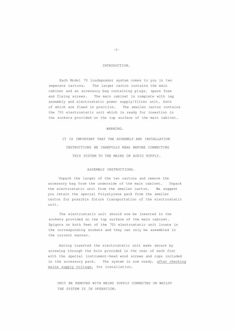
INTRODUCTION.
Each Model 70 loudspeaker system comes to you in two
seperate cartons. The larger carton contains the main
cabinet and an accessory bag containing plugs, spare fuse
and fixing screws. The main cabinet is complete with leg
assembly and electrostatic power supply/filter unit, both
of which are fixed in position. The smaller carton contains
the 701 electrostatic unit which is ready for insertion in
the sockets provided on the top surface of the main cabinet.
WARNING.
IT IS IMPORTANT THAT THE ASSEMBLY AND INSTALLATION
INSTRUCTIONS BE CAREFULLY READ BEFORE CONNECTING
THIS SYSTEM TO THE MAINS OR AUDIO SUPPLY.
ASSEMBLY INSTRUCTIONS.
Unpack the larger of the two cartons and remove the
accessory bag from the underside of the main cabinet. Unpack
the electrostatic unit from the smaller carton. We suggest
you retain the special Polystyrene pack from the smaller
carton for possible future transportation of the electrostatic
unit.
The electrostatic unit should now be inserted in the
sockets provided on the top surface of the main cabinet.
Spigots on both feet of the 701 electrostatic unit locate in
the corresponding sockets and they can only be assembled in
the correct manner.
Having inserted the electrostatic unit make secure by
screwing through the hole provided in the rear of each foot
with the special instrument-head wood screws and cups included
in the accessory pack. The system is now ready, after checking
mains supply voltage, for installation.
UNIT BE REMOVED WITH MAINS SUPPLY CONNECTED OR WHILST
THE SYSTEM IS IN OPERATION.

-3-
INSTALLATION INSTRUCTIONS
MAINS .
Before attempting to connect the mains supply to your Model 70
please check your supply voltage and see that this agrees with
the adjustment made to the system before leaving our factory.
A small red label is attached to the power supply panel
(rear main cabinet) giving this indication
Adjusted for European ( 200 - 240 volts §0 HzJAC.
Adjusted for American ( 110 -125 volts 60 Hz.) AC
Due to the good regulation of the EHT power supply adjustment
of mains voltage will not normally be necessary. All systems
are set before leaving the factory for the market concerned as
shown above.

-4-
(Assembly In struct ion s_-_Main s_-__contd .)_ '-
Should mains voltage adjustment be necessary this is carried
out by removing the power supply and repositioning one wire
on the mains transformer termination board. This work should
be carried out by your dealer who is provided with the necessary
instructions.
Model 70 requires connection to an alternating current mains
supply with the special three pin plug provided with your
accessories. Under normal operating conditions the current
drain is negligible, the load being only some 10 watts
( one tenth that of a normal reading lamp) and provided three
core cable is used for mains connection the core diameter is
in no way critical. The mains cable connections to the three
pin plug are illustrated in Fig. 3 below.
An outer metal screen is built in to the electrostatic unit
for safety purposes. It is important therefore to ensure
that three core cable is used together with a three pin plug
to your mains socket.
AUDIO
The output from your amplifier is connected via the special
2 pin non-reversible plug provided to the socket marked 1 INPUT ' on the power unit rear plate.
The cable (twin or two core) usea for the audio lead should
have low resistance and if more than say ten feet of cable
is required for this lead we would recommend an inner conductor
of 7/029 or similar.
When two loudspeaker systems are operating for stereo
reproduction it is important that the audio connections to
the 'INPUT' socket are correctly phased. The red (or
positive) terminal of your amplifier should be connected to
pin one of the input plug on your loudspeaker.

-5-
Assembly Instructions - Audio - contd.:-
If phasing is correct this is evident by a relatively small
central image when the listener is seated on a centre line
between the loudspeakers and both loudspeakers are fed from a monophonic signal. If phasing is incorrect the sound
image will be much broader and less well defined. A reversal
of the amplifier or loudspeaker connections from one channel
will confirm the correctness of phasing and illustrate this
point.
POSITIONING OF LOUDSPEAKERS IN LISTENING ROOM.
Due to the wide horizontal dispersion of the Model 70 system
loudspeaker placing to obtain an even stereo image is not as
critical as with many conventional systems. It will also
be found that the stereo image is preserved over a wide
listening angle. The suggested placing for a pair of
Model 70 reproducers is illustrated in Fig. 4 below.
Fig. 4.
It is important to realise that the bass response is controlled
under listening conditions by the room dimensions and the
position (relative to walls or corner placing) "which the
loudspeaker occupies. The closer the system is placed to
a wall or corner the greater will be the coupling to the
room. As a general rule those rooms with similar dimensions
( i.e. a square room ) are the most difficult from the
viewpoint of obtaining extended resonant free bass response.
If your listening conditions are such that the bass response
is excessive within a narrow band of frequencies it may be

-6-
it may be found desirable to withdraw the loudspeaker
from the corner or wall by some twelve to twenty-four
inches.
OPERATION,
At the rear of the electrostatic unit will be found a
removable absorbent pad, the function of which is to reduce
rear radiation in locations where the loudspeaker is
placed close to a wall or corner. This pad provides a
useful method of varying the distribution pattern of the
electrostatic unit above 400 Hz. (lower mid. freguencies)
to suit both ambient conditions and the user's personal
preferance in terms of the ratio of direct to reflected sound.
This absorbent pad can be readily withdrawn with the fingers
from its recess in the rear of the 701 electrostatic mount.
With the rear pad withdrawn greater ambience will be experienced
and, depending on the reflective nature of the walls and
furnishings behind the loudspeaker there will be a slight
increase in sound level above 400 Hz with the electrostatic
operating in this condition. If it is desired to operate
Model 70 at very high volume levels or where high powered
continous sine wave inputs are applied the rear absorbent pad
should be placed in position.
It will be observed that on the rear panel of the Power Unit
there is a neon indicator. This shows that mains supply is
functioning. If the neon does not light up when mains is
connected the fuse should be checked. A spare fuse is provided
but repeated replacement should not be made and if this
fails you should consult your dealer.
ANCILLARY EQUIPMENT.
Model 70 probably adds less in terms of colouration and
distortion than any other loudspeaker system in existance.
It will be analytical of the signal which it receives and
therefore benefits from use with ancillary equipment of
the highest available quality.

from electronics manufacturers of
electronic and acoustical
equipment
THE DESIGN & DEVELOPMENT OF
THE MODEL 70
MODEL 70, the first of our loudspeaker systems where all
units are designed and built within our own factory, represents
what we believe to be a successful attempt to produce a
loudspeaker system for the perfectionist which is a worthwhile
advance on existing systems.
INTRODUCTION
In contemplating the design and manufacture of Model 70
certain guide lines were laid down some two years ago at the
commencement of the design programme :-
1) New thinking on the acoustical distribution pattern,
especially within the vitally important mid frequency
region of 400 Hz to 5 kHz, aiming towards exploring
the advantages of a distribution pattern approximating
to spherical.
2) A mid frequency unit capable of handling input powers
in the region of 25 watts r.m.s. with distortion
factors to the order of 0.5% or lower.
3) A really low distortion bass radiator capable of truly
complementing aspects 1) and 2) above without occupying
an unduly large enclosure volume.
4) Exploration of the listening advantages by increasing
reverberant to direct sound.
5) All units be designed and built within our own factory
to ensure maximum quality control and retention of the
exclusive original design.
6) Styling and general appearance to be acceptable in a
wide range of domestic furnishings.

-9-
It was further decided that the concept of Model 70 should
be one of an international product and, whilst paragraph two
detailing a high power handling capacity was consistent with
World markets, certain other design and constructional features
were laid down as being essential :-
a) That the system be in a modular form allowing
easy assembly by overseas agents.
b) That the bass chamber loading, consistent always
with the ultimate performance, be relatively
simple and capable of being accurately copied in
distant markets where it is obviously uneconomical
to ship complete systems.
c) As an extension of 2) that all units be easily
removable to facilitate speedy servicing in overseas
markets where technical service facilities are
limited.
DESIGN PERAMETERS
It has been generally accepted for reasons too well known
to be repeated that, if a loudspeaker system is aiming at
optimum performance, the frequency spectrum should be split.
The precise division of frequencies to be handled by the various
units and reasons for the crossover frequency chosen will be
discussed later in this release, but initially let us survey the
alternatives dealing first with frequencies below 400 Hz.
The alternatives are electrostatic or moving coil units and
it was decided at an early stage in the design that the latter
method showed obvious advantages. For example, on an existing
full range electrostatic loudspeaker very careful measurements
were made and total harmonic distortion at 60 Hz with 15 watt
r.m.s. input was in the region of 50%. On an alternative full
range electrostatic American design which was sampled, the
dimensions of this unit were such as to exclude its use in the
majority of home installations. Whilst a very selected few may
accept panels in their lounge some seven feet high and three
feet Wide it was felt that on appearance alone the points
discussed in the introduction were in no way catered for.
As a result of long discussions between the writer and
Mr. Dennis Ward it was felt that the moving coil system should be

-10-
capable of meeting the initial design requirements set out
in paragraph three above with an enclosure size of some 2 - 3
cubic feet.
In so far as the mid and upper frequencies were concerned
the choice of units was threefold - Moving coil, Electrostatic
or Ionic. It will be noted that the Ionic unit is currently
used in our P2 monitor.
At an early stage in development new alternative Ionic
units were manufactured in prototype form with a view to
increasing power handling capacity and extending the frequency
response at least two octaves below that provided by the
existing Fane unit. Whilst certain progress was made, both
the physical dimensions of the horn loading and the R.F.
oscillator power requirements showed that, although improvement
in the Ionic unit was possible, the disadvantages were those of
physical size and adequate R.F. screening. For instance, one
prototype had a horn length of some two feet and an R.F.
oscillator of 70 watts, a totally unmanageable quality both in
terms of size and adequate screening to provide freedom from
T.V.I. For these reasons the Ionic method was dismissed and
attention focused on Electrostatic and Moving coil units.
Although considerable advance has been made in the design
and development of Moving coil units they do not, in the writer's
opinion, approach the Electrostatic transducer in so far as low
distortion, transient behaviour or flexibility of broad polar
distribution.
Evaluations carried out by Mr. Harwood on a somewhat similar
'state of the art' project and, for those interested, reference
may be made to three articles published in "Wireless World" in
1968 where it was shown that even offering an idealised Moving
coil unit to a slot radiator, the polar characteristic was not
well maintained above 3 kHz. It was decided, therefore, to
explore the possibility of making an electrostatic unit, working
from first principles with a view to comparative measurements
between the Electrostatic and Moving coil units which could be
developed.
Some six months after the design programme was originated
a series of prototype units were produced which enabled a prime

-11-
decision to be taken that the Electrostatic transducer, subject
to performance being the first consideration and price secondary,
was the best method to approach the final design. The
following conditions on the basic design were, therefore,
decided upon :-
1) That the bottom four octaves should be dealt with
by Moving coil unit and that a development
programme be launched to meet the stringent
requirements laid down.
2) That an Electrostatic transducer be developed
for frequencies above 400 Hz with the possible
addition of a "super tweeter", should this be
found to be necessary. That within this basic
design considerable work would be needed in
terms of improved distribution pattern and
increased power handling capacity on Electrostatic
units. Existing samples which were measured
showed this to be two of their weaker features.
DETAILED DISCUSSION ON BASIC UNITS FORMING THE
COMPLETED MODEL 70 SYSTEM
Mid High Frequency Electrostatic Unit.
It is not the intention of this release to provide
production techniques or information which have been expensive
both in terms of time and effort and which have made it
possible for us to successfully manufacture an Electrostatic
unit. Sufficient to say that at an early stage full reference
was made to all existing patents on Electrostatic units as it
was in no way our intention to infringe these and to produce
new material on which we ourselves could lay patent claims.
The problems which we overcame concerned such matters as
diaphragm stability, methods of diaphragm coating, A.C.
protective insulation as between fixed plates, mechanical
stability and many other factors which, to the uninitiated, may
seem simple but formed a major part of the considerable
development expense in which we have been involved.

-12-
FIG 2
Early experimental
electrostatic unit
comprising 6 separate
modules
Fig 2 illustrated above shows one of the early
experimental Electrostatic units which we made. This
assembly, consisting of some six modules, was the prime
factor in deciding to proceed with the Electrostatic
transducer. Tone burst oscillograms and freedom from
harmonic distortion were quite superlative. Its principal
limitations were, however, threefold :-
1) High diaphragm resonance
2) Poor polar distribution
3) Low acoustical output
Early prototypes of the Electrostatic unit consisted of
various assemblies comprising from four to sixteen of the
experimental plates illustrated were arranged in every
imaginable combination. As the majority of these units were
individually produced this part of the development took some
two months. Whilst yielding much useful information it
pointed to the inescapable truth that the Electrostatic
transducer, behaving as it does in a true piston fashion, must
offer a curved surface if freedom from serious phasing problems
within the mid frequency.region- is to be avoided.
The outcome of all the foregoing work was the decision to
develop an Electrostatic unit
a) of adequate area to provide the
acoustical output required
b) with a continuously curved surface to
provide the smooth horizontal distribution
required, making the vertical dimensions
relative to length sufficiently small to
approximate to a live source.

-13-
Handmade prototypes were constructed of various
dimensions and the initial concept was that this unit should
be mounted vertically. It was found however, that whilst
excellent results could be obtained, the practical dimensions
of such a unit made it totally impossible to accommodate.
For instance, a vertical curved unit one inch in width would
become very directional at 10 kHz and would require a length
of some eight feet to provide a similar radiating area to that
of the final 701 assembly.
Parallel with the work which was being carried out on
shape, size and configuration of the Electrostatic unit the
possibility of providing a curved free-standing horizontal
radiator became an increasingly obvious solution. Figs. 3 and
4 below illustrate the final Electrostatic assembly.
FIG 3
Model 701
Electrostatic unit
front view
FIG 4
Model 701
Electrostatic unit
with WtM cover
removed
The polar diagrams, illustrated in Figs. 5 and 6 indicate
the wide and extremely even polar response achieved from the
final 701 assembly. Even at 15 kHz, over an 80 deg. arc - 2 db.
is maintained. All measurements taken in our anechoic chamber
with all B & K equipment, using type 4133 half inch calibration
microphone

•14-
FIG 5
General polar
diagram of Model 70
illustrating wide
and even horizontal
distribution
FIG 6
Horizontal
distribution
Model 70 at 15 kHz
-15-
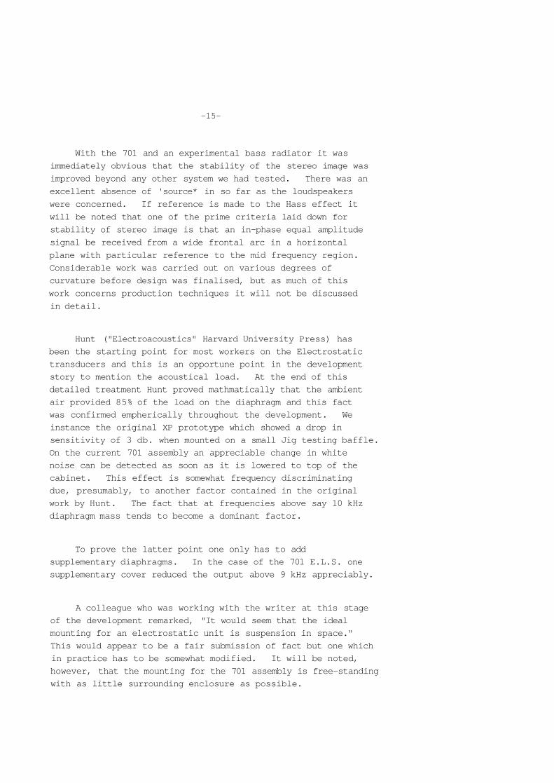
With the 701 and an experimental bass radiator it was
immediately obvious that the stability of the stereo image was
improved beyond any other system we had tested. There was an
excellent absence of 'source* in so far as the loudspeakers
were concerned. If reference is made to the Hass effect it
will be noted that one of the prime criteria laid down for
stability of stereo image is that an in-phase equal amplitude
signal be received from a wide frontal arc in a horizontal
plane with particular reference to the mid frequency region.
Considerable work was carried out on various degrees of
curvature before design was finalised, but as much of this
work concerns production techniques it will not be discussed
in detail.
Hunt ("Electroacoustics" Harvard University Press) has
been the starting point for most workers on the Electrostatic
transducers and this is an opportune point in the development
story to mention the acoustical load. At the end of this
detailed treatment Hunt proved mathmatically that the ambient
air provided 85% of the load on the diaphragm and this fact
was confirmed empherically throughout the development. We
instance the original XP prototype which showed a drop in
sensitivity of 3 db. when mounted on a small Jig testing baffle.
On the current 701 assembly an appreciable change in white
noise can be detected as soon as it is lowered to top of the
cabinet. This effect is somewhat frequency discriminating
due, presumably, to another factor contained in the original
work by Hunt. The fact that at frequencies above say 10 kHz
diaphragm mass tends to become a dominant factor.
To prove the latter point one only has to add
supplementary diaphragms. In the case of the 701 E.L.S. one
supplementary cover reduced the output above 9 kHz appreciably.
A colleague who was working with the writer at this stage
of the development remarked, "It would seem that the ideal
mounting for an electrostatic unit is suspension in space."
This would appear to be a fair submission of fact but one which
in practice has to be somewhat modified. It will be noted,
however, that the mounting for the 701 assembly is free-standing
with as little surrounding enclosure as possible.

-16-
The writer has an objection to the reproduction of soloists
appearing some twelve to eighteen inches from the floor and for
this reason the E.L.S. unit on Model 70 is located approximately
at ear level when seated.
The whole project of developing the electrostatic unit has
proved so extensive that it would require a work of much greater
scope than this short article to deal with even a reasonable
proportion of the subject matter. The writer does, however,
feel some satisfaction in setting out in print certain basic
principles which few other manufacturers have attempted to
discuss.
CROSSOVER & FILTER NETWORK
The crossover and filter network of the Model 70 is split
into two sectors. These are illustrated by Figs. 7 - 1 0 below.
FIG 7
Model 70 power
assembly unit
E.L.S. matching
and .filter
network, removed
from cabinet
and' mated
with 701
FIG 8
Model 70 power
supply unit as
above, top view

-17-
FIG 9
Model 70 Bass
Radiator low pass
section
FIG 10
Underside of
Model 70 power
supply showing
E.L.S. matching
transformer and
various component
parts.
Before discussing all design and electrical characteristics
of these units it may be of interest to note from Figs. 7 - 1 0
how stray capacities have been reduced to a minimum by careful
design and positioning of units. This factor plays an
important part in sensitivity and "top octave" performance of
electrostatic units.
A poor crossover unit or incorrectly chosen crossover
frequencies can mar an otherwise good loudspeaker system. The
writer has always felt that somewhere in the 400 Hz to the 600 Hz

-18-
region was the correct one in terms of minimal intermodulation
distortion within the all important mid frequency band. Due
to the successful completion of the 701 design, a crossover
frequency of 500 Hz was possible and proved successful in all
respects.
The high pass filter of an electrostatic unit requires
special consideration if the full potential of the unit is to
be realised. Attention must be paid to tailoring the stop
band response to the required slope rate. The natural response
of an electrostatic assembly is to rise very steeply immediately
at diaphragm resonance and produce an almost impossible matching
characteristic for the bass radiator. This rise is controlled
partially by accurate diaphragm tension but one must also
restrict input within the first octave above resonance and,
coupled with the falling impedance characteristic of the
capacity load, the E.L.S. presents different and somewhat
exacting requirements in terms of filter network.
The remainder of the crossover unit on Model 70 is
conventional but it is worth mentioning that no less than 74
mfd. of paper is used in this circuit - at a cost of one
component that would almost buy a cheap loudspeaker system.
Reversible electrolytic capacitors whilst satisfactory at A.C.
powers for a limited period of use become conductive and render
the filter network useless under the stringent conditions laid
down for a system such as Model 70.
One final component worthy of mention is the series feed
inductor on the high pass section. This component can
seriously modify the controlling feedback applied to the voice
coil and, because it handles considerable current, we designed
a special ferrite inductor which reduced the D tot. at 25 watts
input to well below 0.5% at all frequencies from 30 Hz.
Conventional components sampled showed figures in the region of
2.5%

x -19-
BASS RADIATOR
FIG 11.
DW 13/3, final
production version
as used in the
Model 70
It was mentioned earlier in the introductory discussion
the reasons for choosing the moving coil as opposed to the
electrostatic principle for the lowest four octaves of the
system. The requirements set out for the final performance
of this unit were that it should match as closely as possible
in all respects that of the 701 electrostatic unit. The
writer's colleague, Mr. Dennis Ward, despite some twenty years
experience in the design and manufacture of moving coil units
felt that a distortion factor in the order 1% with inputs of
25 watts was a somewhat impossible task. However, work was
commenced on prototypes with a view to exploring the possibility
of a very long throw linear suspension unit working as a true
piston.
A piston area (nominal 12") was chosen as being reasonably
consistent with the enclosure volume to build a final system with
a resonance below 40 Hz and a free air resonance in the region,
of 18 - 22 Hz.

-20-
Expanded polystyrene seemed the obvious choice for cone
material as medium and high freguencies were not involved and
indeed a number of early prototypes were made with this material.
Extended listening tests proved, however, that the polystyrene
cone material showed 'read out' colouration within the 200 - 400
Hz region. Experiments were then made with an exactly similar
unit minus the polystyrene slab and girder assembly and it was
determined by relating frequency response curves to the two
units that energy generated primarily at the apex of the cone
was largely being lost, presumably due to kinetic conversion
within the polystyrene, and in turn the polystyrene was
partially breaking up and providing this small but objectionable
colouration.
The final cone assembly does, in fact, consist of a
laminated structure in order to provide the required stiffness
and is further braced and mass adjusted by small rectangular
sections of synthetic rubber affixed at critical positions on
the front face of the cone.
One of the relatively untouched aspects of bass radiator
design has been the effective 'Q' at resonance. A simple
bridge method was evolved for this measurement and considerable
work carried out in terms of suspension compliance and diaphragm
mass to reduce this figure well below unity. Until ambient
room measurements were taken it was not fully realised how 'room
gain' could play an important part in magnifying a relatively
small rise in the response as shown on an anechoic plot to an
objectionable one note thump.
LOUDSPEAKER MEASUREMENTS
The writer is a firm believer in measurement at all stages
of design and production. Although designers in the past have
suggested that the measurement of loudspeaker response is of
secondary consideration, we feel that this view is taken because
the art of interpretating loudspeaker measurements is a subject
on which there is considerable scope for development. For
instance many manufacturers and designers proudly publish a
beautiful axial plot of their system and whilst a straight line
response is a good starting point this measurement is almost
-21-
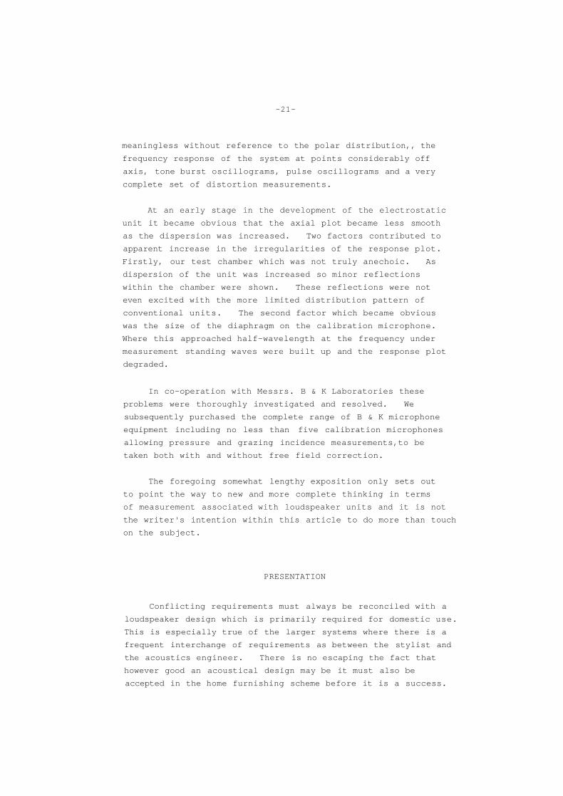
meaningless without reference to the polar distribution,, the
frequency response of the system at points considerably off
axis, tone burst oscillograms, pulse oscillograms and a very
complete set of distortion measurements.
At an early stage in the development of the electrostatic
unit it became obvious that the axial plot became less smooth
as the dispersion was increased. Two factors contributed to
apparent increase in the irregularities of the response plot.
Firstly, our test chamber which was not truly anechoic. As
dispersion of the unit was increased so minor reflections
within the chamber were shown. These reflections were not
even excited with the more limited distribution pattern of
conventional units. The second factor which became obvious
was the size of the diaphragm on the calibration microphone.
Where this approached half-wavelength at the frequency under
measurement standing waves were built up and the response plot
degraded.
In co-operation with Messrs. B & K Laboratories these
problems were thoroughly investigated and resolved. We
subsequently purchased the complete range of B & K microphone
equipment including no less than five calibration microphones
allowing pressure and grazing incidence measurements,to be
taken both with and without free field correction.
The foregoing somewhat lengthy exposition only sets out
to point the way to new and more complete thinking in terms
of measurement associated with loudspeaker units and it is not
the writer's intention within this article to do more than touch
on the subject.
PRESENTATION
Conflicting requirements must always be reconciled with a
loudspeaker design which is primarily required for domestic use.
This is especially true of the larger systems where there is a
frequent interchange of requirements as between the stylist and
the acoustics engineer. There is no escaping the fact that
however good an acoustical design may be it must also be
accepted in the home furnishing scheme before it is a success.

mm
-22-
At a fairly advanced stage in the styling programme it
was decided to offer a limited number of alternative designs
for public comment at both the Amsterdam and London
International Exhibitions and from customer opinion sampled
it was decided to produce the horizontal styling detailed in
Fig. 12 below.
Fig. 12
MODEL 70, Horizontal Styling - Front and Side Elevations

-23-
It is our intention, towards the middle of 1970, to.
produce a free standing vertical styling for Model 70.
The line drawings in Fig. 12 and the half tone photograph
at the beginning of this release will provide a reasonable
indication of the final horizontal styling. A few additional
comments may however be helpful. The fabric covering the
main Bass Chamber is of an unusually interesting texture, of
a golden beige colour it matches well with the oiled teak or
American Walnut veneers. For reasons of safety the
electrostatic unit is sealed in a grounded expanding metal
cover but this has been anodised to colour match the fabric of
the main enclosure.
The proportions of the Bass Chamber and its leg assembly
minimise detraction effect and the height of the finished
loudspeaker system allows the electrostatic unit to be at ear
level when seated.
To assist movement on a carpeted surface and to distribute
the not inconsiderable weight the leg structure has a return
member which may be seen from the side elevation of Fig. 12.
Although fitting castors was contemplated it was found that
the centre of gravity was somewhat too high for stability.
Considerable attention has been paid to both enclosure
finish and construction. The main Bass Chamber is constructed
of 24 mm 650 density chipboard, veneered on both surfaces.
The cabinet is veneered on all surfaces including the back in
high guality matching veneers and the electrostatic top mount
and leg structure are also in matching veneers or solid timber.
RESPONSE CURVES, OSCILLOGRAMS AND FINAL MEASUREMENTS
The following reproduction of response plots and
oscillograms have been taken from a standard production sample
of the completed Model 70. They will serve to indicate the
performance of the complete system and illustrate aspects of
loudspeaker measurement discussed earlier in this release.

-24-
Fig. 13 Fig. 14
Figures 13 and 14 above are of special interest as they
show the difference in the bottom three octaves between our
own anechoic chamber (Fig. 13) - note 'room gain' below 100 Hz
and the Northern Polytechnic (Fig. 14) which is very much more
accurate at these low frequencies.
All the following measurements are taken in our own
anechoic chamber where allowance must be made for the difference
illustrated above.
Fig. 15
The above response plot indicates 'on Axis' standard
Model 70, B & K Model 4133 microphone pressure operated.
-25-
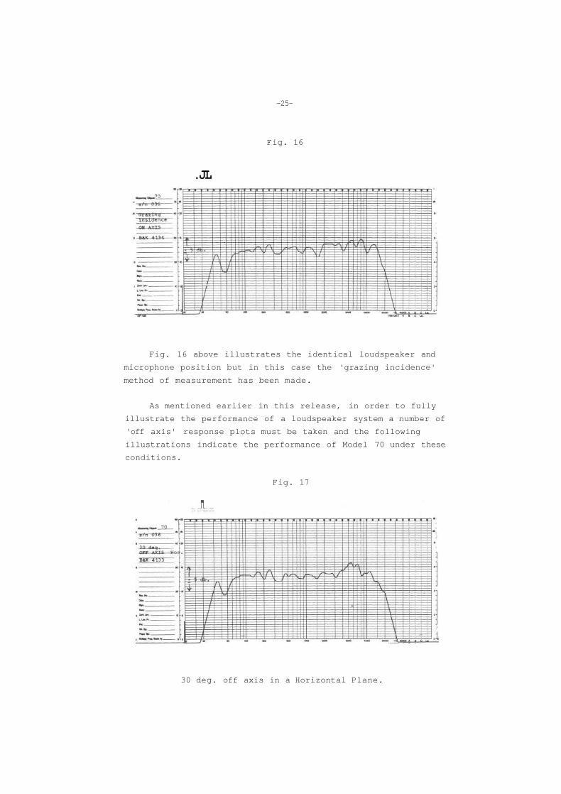
Fig. 16
.JL
Fig. 16 above illustrates the identical loudspeaker and
microphone position but in this case the 'grazing incidence'
method of measurement has been made.
As mentioned earlier in this release, in order to fully
illustrate the performance of a loudspeaker system a number of
'off axis' response plots must be taken and the following
illustrations indicate the performance of Model 70 under these
conditions.
Fig. 17
30 deg. off axis in a Horizontal Plane.

-26-
Fig. 16
. J l__
45 deg. off axis in a Horizontal Plane,
Fig. 19
15 deg. off axis in a Vertical Plane.
We now follow the range of frequency response plots with
tone burst and pulse oscillograms. These oscillograms have
all been recorded in our own anechoic chamber using the B & K
•J inch calibration microphone type 4133.

-27-
Fig. 20
Group I T.B. Oscillograms on 8 off
10 kHz 15 kHz 20 kHz
Bottom trace indicates input, upper microphone output.

-28-
Fig. 21
Group 2 T. B. Oscillograms 64 on 32 off
500 Hz 1.0 kHz 5 kHz
3.5 kHz 10 kHz 15 kHz
Fig. 22
Pulse Response
300 Hz 500 Hz

-29-
Fig. 23
Power Oscillograms 25 watts R.M.S. in to 8 ohms.
60 Hz 1 kHz
A more meaningful indication of distortion under power is
given from the following table : -
D tot. with input pf 25 watts R.M.S. (8 ohms)
B & K 4113 -J" Quad 33 B & K Line and Mic. Amps
30 Hz 40 Hz 50 Hz 60 Hz 100 Hz 200 Hz
12% 10% 8% 2.5% 1.5% 1.4%
300 Hz 400 Hz 500 Hz 500 Hz 1 kHz 3 kHz
1.4% 0.5% 0.3% 1.0% 1.1% 0.3%
5 kHz
0.8%
POLAR RESPONSE
By way of further illustrating the extremely wide
dispersion of Model 70 we now exhibit all polar diagrams
in Fig.24.

-30-
Fig. 24
General polar diagram of production Model 70 showing
1 kHz, 5 kHz and 10 kHz polar response.
SUMMARY OF DETAILED SPECIFICATION
UNITS
Nominal 13" diameter circular Bass Radiator with laminated and specially reinforced cone - Type DW 13/3. Eleven module wide dispersion electrostatic unit, Type 701, covering freguencies above 400 Hz. Model 70 power supply unit together with high and low pass section, electrostatic matching transformer and bass low pass filter assembly contained on separate board.

-31-
ACOUSTICAL LOADING
Bass unit infinite with multiple bracinq and synthetic fibre absorbents. Electrostatic unit free standing plug-in assembly with removable rear absorbent pad allowing polar distribution to be modified depending on ambient conditions.
CABINET
Constructed throughout of 24 mm. 650 density chipboard veneered on inner and outer surfaces. Cabinet foot assembly and 701 electrostatic unit covered in matching veneer of oiled Teak or oiled American Walnut with main cabinet body veneered on all surfaces including the back.
IMPEDANCE
Nominal 8 ohms rising approximately 25 ohms at 1 kHz but not falling below 4 ohms at 20 kHz.
POWER HANDLING CAPACITY
25 watts R.M.S. (50 watts music) throughout entire frequency range.
DIMENSIONS
FREQUENCY RESPONSE
50 Hz to 15 kHz better than
40 Hz to 20 kHz - 5 db.
4 db.
AXIAL RESPONSE
90 degrees arc horizontal in the order of - 2 db. of an axis response at all frequencies up to 15 kHz.

-32-
DISTORTIQN
D tot. with input of 25 watts R.M.S. (8 ohms)
B & K 4113 -J" Quad 33. B & K Line and Mic. Amps.
30 Hz 12%
300 Hz 1.4%
SYSTEM
40 Hz 10%
400 Hz 0.5%
RESONANCE
50 Hz 8%
500 Hz 0.3%
60 Hz 2.5%
500 Hz 1.0%
100 Hz 1.5%
1 kHz 1.1%
200 Hz 1.4%
3 kHz 0.3%
5 kHz 0.8%
40 Hz ± 1%
(System ?Q ! below unity in the order of 0.9)
AMPLIFIER REQUIREMENT
The Model 70 is capable of handling large inputs without distortion but to obtain the full benefit from this very low distortion system it is recommended that amplifiers with an R.M.S. output of over 30 watts per channel be used.
With modern amplifiers stability with capacity load is usually well maintained but it is important to note that, due to the unavoidable impedance rise at mid-frequency, amplifiers of generous power output (normally specified in the 8 ohms load) should be used. The following amplifiers have been used in our Laboratory and Listening Room throughout development and have proved completely satisfactory.
QUAD 33 DYNACO 120 SONY 1120
QUAD 50 SUGDEN 25 watts Class A RADFORD 100 watts valve
GENERAL PERFORMANCE
The detailed frequency response plots and oscillograms reproduced in this release indicate a very high standard of performance achieved in the final product.
CONCLUSION
In concluding the design story I should like to pay
particular tribute to the hard and untiring efforts of my
colleagues, Mr. Dennis Ward and Mr. J. R. Greenwood,
without whose help the project would not have been possible.
We feel considerable pride in announcing this, the
first generation of loudspeaker systems where all units are
designed and manufactured within our own Factory and we
confidently offer this system as representing a worth while
advance in the search for ultimate perfection.

Printed in England
The manufacturers reserve the right to amend or modify this specification without notice.