Embed Size (px)
Citation preview

PARTS AND OPERATION MANUAL
Revision #4 (05/29/07)
MODEL ST-70Structural Concrete Pump
(Hatz Diesel Engine)
THIS MANUAL MUST ACCOMPANY THE EQUIPMENT AT ALL TIMES.
To find the latest revision of thispublication, visit our website at:
www.multiquip.com

PAGE 2 — ST-70 — PARTS & OPERATION MANUAL — REV. #4 (05/29/07)
Diesel engine exhaust and some of

ST-70 — PARTS & OPERATION MANUAL — REV. #4 (05/29/07) — PAGE 3
NOTE PAGE
PAGE 4 — ST-70 — PARTS & OPERATION MANUAL — REV. #4 (05/29/07)
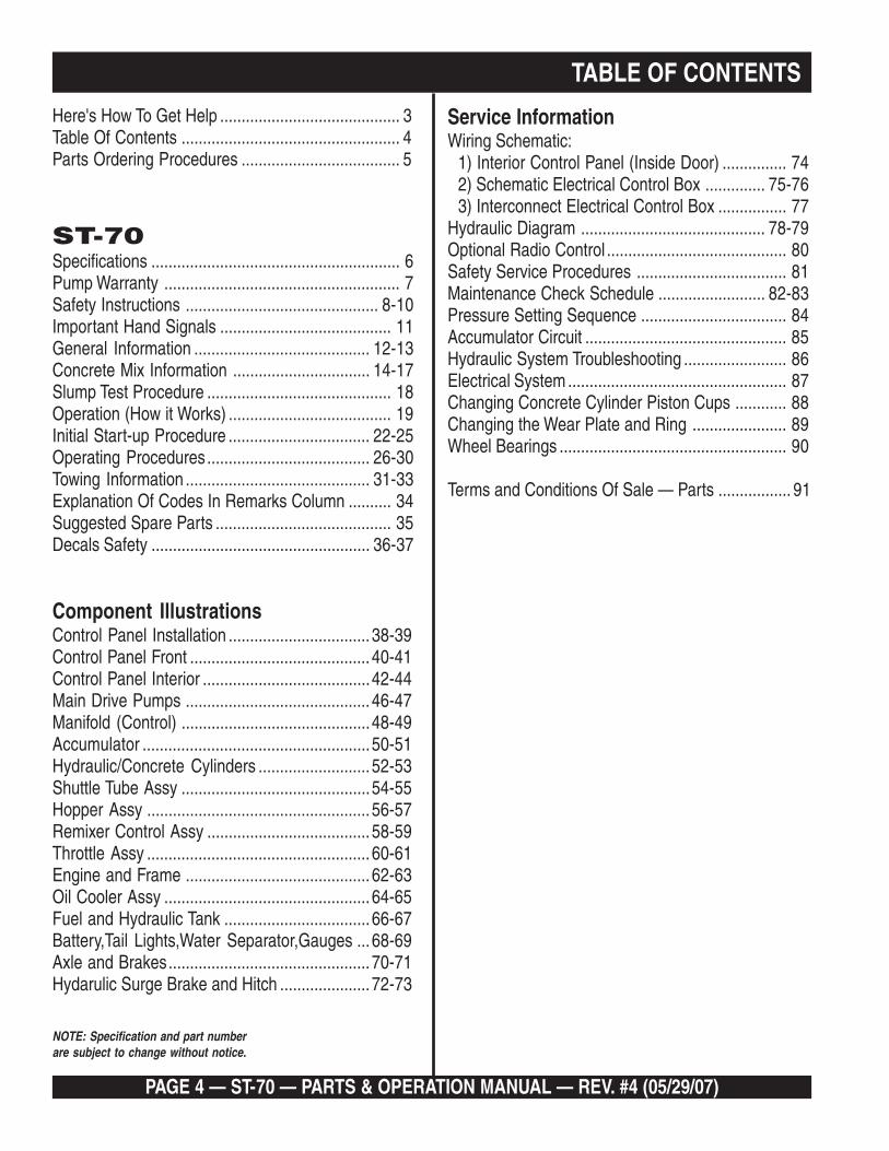
Here's How To Get Help .......................................... 3Table Of Contents ................................................... 4Parts Ordering Procedures ..................................... 5
ST-70Specifications .......................................................... 6Pump Warranty ....................................................... 7Safety Instructions ............................................. 8-10Important Hand Signals ........................................ 11General Information ......................................... 12-13Concrete Mix Information ................................ 14-17Slump Test Procedure ........................................... 18Operation (How it Works) ...................................... 19Initial Start-up Procedure ................................. 22-25Operating Procedures...................................... 26-30Towing Information ........................................... 31-33Explanation Of Codes In Remarks Column .......... 34Suggested Spare Parts ......................................... 35Decals Safety ................................................... 36-37
Component IllustrationsControl Panel Installation ................................. 38-39Control Panel Front .......................................... 40-41Control Panel Interior .......................................42-44Main Drive Pumps ........................................... 46-47Manifold (Control) ............................................48-49Accumulator .....................................................50-51Hydraulic/Concrete Cylinders ..........................52-53Shuttle Tube Assy ............................................54-55Hopper Assy .................................................... 56-57Remixer Control Assy ......................................58-59Throttle Assy .................................................... 60-61Engine and Frame ...........................................62-63Oil Cooler Assy ................................................64-65Fuel and Hydraulic Tank ..................................66-67Battery,Tail Lights,Water Separator,Gauges ...68-69Axle and Brakes............................................... 70-71Hydarulic Surge Brake and Hitch ..................... 72-73
TABLE OF CONTENTS
NOTE: Specification and part numberare subject to change without notice.
Service InformationWiring Schematic:
1) Interior Control Panel (Inside Door) ............... 742) Schematic Electrical Control Box .............. 75-763) Interconnect Electrical Control Box ................ 77
Hydraulic Diagram ........................................... 78-79Optional Radio Control .......................................... 80Safety Service Procedures ................................... 81Maintenance Check Schedule ......................... 82-83Pressure Setting Sequence .................................. 84Accumulator Circuit ............................................... 85Hydraulic System Troubleshooting ........................ 86Electrical System ................................................... 87Changing Concrete Cylinder Piston Cups ............ 88Changing the Wear Plate and Ring ...................... 89Wheel Bearings ..................................................... 90
Terms and Conditions Of Sale — Parts ................. 91

Discount Equipment Rental is your online resource for commercial and industrial quality equipment sales and rentals. We sell worldwide for the brands Genie, Terex, Stihl, JLG, Multiquip, Mayco, Stone, Diamond Products, Airman, Mustang, Power
Blanket. We have complete rental locations throughout Florida.
Locations:
West Palm Beach – 561-964-4949
Orlando – 407-291-3162
Tampa – 813-248-2848
Need parts? Check out our website at www.discount-equipment.com
Can’t find what you need? Click on this link http://www.discount-equipment.com/category/5443-parts/ and fill out the request form. Make sure you have your machines model and serial number available in order to help us get you the correct parts. One of our experienced staff members will get back to you with a quote for the right part that your machine needs.

PAGE 6 — ST-70 — PARTS & OPERATION MANUAL — REV. #4 (05/29/07)
ST-70 SPECIFICATIONSPERFORMANCE U.S. METRICPumping Rate — Volume Output 70 yd/hr.* (54m/hr)*Maximum Aggregate Size 1 1/2" minus (38 mm)
Verticle Pumping Height ................................................. 300 ft.* ..................................................................... (91m)*
Horizontal Pumping Distance ......................................... 1200 ft.* ................................................................... (366m)*
Engine — Diesel ............................................................. HATZ 4M40L: 80HP(59.68KW)
Hopper Capacity 10 cu. ft. capacity with optional forward/reverse re-mixer
Line Size ........................................................................ 3", 4" or 5" dia.
Electrical System ............................................................ 12 v D.C.
Hydraulic Oil System ...................................................... 58 gal.
Fuel Tank Capacity ......................................................... 20 gal.
Weight (with fluids) ......................................................... 4700 lb. ................................................................... (2132kg)
Tire Size ......................................................................... 7.35 - 14, 8 ply
Brakes ............................................................................ 12" dia. Hydraulic Surge
All Steel Trailer Frame
DIMENSIONS
L x W x H ........................................................................ 149" X 67" X 55" ...................................................... (356 X 170 X 140cm)
Weight (Shipping) ........................................................... 4,700 lbs. ................................................................ (2132kg)
*These figures will vary with Pump Model, concrete mix design, line size, job site conditions and engine option.
Mayco reserves the right to change and modify the above specifications or design without notice or obligation.

ST-70 — PARTS & OPERATION MANUAL — REV. #4 (05/29/07) — PAGE 7
MAYCO PUMP WARRANTYMechanical Drive Models
MAYCO PUMP, hereinafter referred to as “Manufacturer’,warrants each new Mayco Pump sold by the manufacturer tobe free from defects in material and workmanship, undernormal use and service, for a period of one year after the dateof delivery to the original retail purchaser. Manufacturer will, atits option, replace or repair at a point designated by theManufacturer any part or parts which shall appear to thesatisfaction of the Manufacturer upon inspection at such pointto have been defective in material or workmanship. Thiswarranty does not obligate the Manufacturer to bear anytransportation charges or labor charges in connection withthe replacement or repair the of the defective parts.
This warranty does not apply to any pump if attempts havebeen made to pump concrete materials which haveseparated, to any pump which has been repaired with otherthan Genuine Mayco Parts, nor to any pump which has beenaltered, repaired or used in such manner as to adversely affectits performance, nor to normal service or maintenance or whereblockages have developed within the pump manifold orplacing line or which has been operated in any other mannernot recommended by the Manufacturer. Due to the abrasivenature of concrete, Mayco does not cover natural componentwear.
THIS WARRANTY AND MANUFACTURER’S OBLIGATIONHEREUNDER, IS IN LIEU OF ALL OTHER WARRANTIES,EXPRESS, IMPLIED OR STATUTORY AND ALL OTHEROBLIGATIONS OR LIABILITIES INCLUDING SPECIAL ORCONSEQUENTIAL DAMAGES OR CONTINGENT LIABILITIESARISING OUT OF THE FAILURE OF ANY PUMP OR PARTTO OPERATE PROPERLY, INCLUDING ANY WARRANTIESOF MERCHANTABILITY OR FITNESS FOR A PARTICULARPURPOSE.
Hydraulic Drive Models
MAYCO PUMP, hereinafter referred to as “Manufacturer”,warrants each new Mayco Pump sold by the manufacturer tobe free from defects in material and workmanship, undernormal use and service, for a period of one year or 2000 hoursafter the date of delivery to the original retail purchaser. TheManufacturer will, at its option, replace or repair at a pointdesignated by Manufacturer any part or parts which shallappear to the satisfaction of Manufacturer upon inspection atsuch point to have been defective in material or workmanship.This warranty does not obligate Manufacturer to bear anytransportation charges or labor charges in connection withthe replacement or repair of the defective parts.
This warranty does not apply to any pump if attempts havebeen made to pump concrete materials which haveseparated, to any pump which has been repaired with otherthan Genuine Mayco Parts, nor to any pump which has beenaltered, repaired or used in such manner as to adversely affectit’s performance, nor to normal service or maintenance orwhere blockages have developed within the pump manifoldor placing line or which has been operated in any other mannernot recommended by the Manufacturer. Due to the abrasivenature of concrete, Mayco does not cover natural componentwear.
THIS WARRANTY AND MANUFACTURER’S OBLIGATIONHEREUNDER, IS IN LIEU OF ALL OTHER WARRANTIES,EXPRESS, IMPLIED OR STATUTORY AND ALL OTHEROBLIGATIONS OR LIABILITIES INCLUDING SPECIAL ORCONSEQUENTIAL DAMAGES OR CONTINGENT LIABILITIESARISING OUT OF THE FAILURE OF ANY PUMP OR PARTTO OPERATE PROPERLY, INCLUDING ANY WARRANTIESOF MERCHANTABILITY OR FITNESS FOR A PARTICULARPURPOSE.

PAGE 8 — ST-70 — PARTS & OPERATION MANUAL — REV. #4 (05/29/07)
READ THIS PARTS AND OPERATION MANUALTHOROUGHLY BEFORE USING THIS MACHINE. It describesthe safe, proper and most efficient way to operate it. KNOWYOUR MACHINE!
When operating concrete pumps the safety regulations ofthe responsible employers’ liability insurance company mustbe observed. The observation of these regulations shall bethe responsibility of the contractor and operator.
The following are some supplementary recommendations:
All safety devices and provisions against accidents such aswarning labels and information signs, coverings, etc. mustbe in place. Do not remove or tamper with them. If they aremissing, replace them.
Check the operational reliability of the machine each timebefore it is put into operation. Any defects found must berepaired immediately.
Allow the machine to be operated and maintained by qualifiedpersonnel only.
Before leaving the machine, protect it from unauthorized useand unintentional movements.
Unauthorized presence in the immediate area of the concretepump is not allowed. Warn persons who are in the immediatearea. Stop work if persons do not leave the area after havingbeen warned.
Wear personal protective equipment when operating themachine.
WWWWWARNING! DANGER OF AMPUTARNING! DANGER OF AMPUTARNING! DANGER OF AMPUTARNING! DANGER OF AMPUTARNING! DANGER OF AMPUTAAAAATION!TION!TION!TION!TION!Never place your hands or any part of your body in the hopperor allow anyone else to do so while the engine is running orwhen there is accumulator hydraulic pressure or series injurycould result.
ST-70 — SAFETY INSTRUCTIONS
TRAVEL AND TRANSPORTATIONThe machine must not be moved with extended outriggers.
Before traveling, check the transportation safety devices ofthe outriggers, the tire pressure and the functioning of thebrakes.
Use hoisting units with transport devices complying with safetyrequirements.
Hoisting cables or equipment are to be applied only at thelifting points provided.
TOWING:
1. Read the Atwood Hydraulic Surge Brake InstallationInstructions.
2. The pump should not be towed in excess of 55 MPH (lessdepending on road conditions). It can be towed with anytruck rated to pull a 5000 lb. load.
3. Before towing, check with local and state laws for propercompliance. (Refer to page 31)
a. Secure the hitch on the ball and attach the breakawaycable and safety chain to the towing vehicle.
b. Raise all stand pipes and secure.
4. Use only a 2” one-piece, all-steel, machined or forged ballrated at 5000 lbs. minimum capacity.
5. Do not tow the pump with concrete in the hopper.
6. Do not tow the pump with the concrete reducers attached.
7. Check all wheel lug bolts for proper tightness prior to towing.

ST-70 — PARTS & OPERATION MANUAL — REV. #4 (05/29/07) — PAGE 9
ST-70 — SAFETY INSTRUCTIONS
STABILIZER JACK
Prior to jacking check the soil conditions. If necessary, enlargethe support foot area by placing square timbers underneath.
Keep a sufficient distance from excavations; slopes could breakaway because of support pressures.
On inclines and slopes place chocks behind the wheels.
Jack the pump in such a manner that it is in a horizontal (level)position. Check the position of the pump frequently.
CONCRETE PUMP
To avoid splashes due to suction of air, the agitator hoppermust always be filled with concrete up to the mixing shaft.
DO NOT OPERATE ANY CONCRETE PUMPWITHOUT THE HOPPER GRILL FIRMLY INPLACE.
NEVER ALLOW ANY HANDS NEAR THESHUTTLE CRANK VALVE OR IN THEAGITATOR HOPPER WHILE THE MACHINEIS RUNNING.
WARNING! DANGER OFWARNING! DANGER OFWARNING! DANGER OFWARNING! DANGER OFWARNING! DANGER OFAMPUTAMPUTAMPUTAMPUTAMPUTAAAAATION!TION!TION!TION!TION!Never place your hands or any part of yourbody in the hopper or allow anyone else to doso while the engine is running or when thereis accumulator hydraulic pressure or seriesinjury could result.
Refer to Operation section of this manual for more details.
PIPELINES
PIPELINES AND CLAMPS MUST BE OF SUFFICIENT SIZEFOR THE PUMP’S CAPACITY.
The pipeline connections must not be opened under workingpressure. Before the pipeline is opened, pressure must berelieved by sucking back the concrete. Secure the couplingsafter the assembly of the pipeline.
When laying pipeline use as few bends as possible. Horizontalpipelines must be adequately supported. When installing avertical pipeline, the best method is to use upright struts thatcan be anchored to the building.
It is preferable to install pipelines within the building wheneverpossible. See Operator’s Manual and “Pumping Concrete”booklets for more information on pipeline installations.
MAINTENANCE AND REPAIR
TURN OFF THE ENGINE ANDDISCONNECT THE BATTERY CABLESBEFORE PERFORMING ANYMAINTENANCE OR REPAIRS.
MAKE SURE THAT THE ACCUMULATOR PRESSURE GAUGEREADS ZERO BEFORE ALLOWING ANYBODY TO PUTTHEIR HANDS INTO HOPPER OR SHUTTLE AREA.
Refer to maintenance section of this manual for more details.
CAUTION:If the hoses or lines are blocked for anyreason, or if the lines are kinked whenstarting up or during the pumping cycle, thepump pressure could straighten out the kinkor force out the blockage. This rapid surge of
material could cause the lines to whip or move in such a mannerthat it could cause injury to anyone working near the hossesor lines.
When moving hoses from one site application to another, it isimportant to walk the entire system and visually inspect forany kinks or sharp bends in the hose. You must and straightenthem before starting or resuming the pumping operation.
Inspect the lines at all times to prevent the above conditions.
PAGE 10 — ST-70 — PARTS & OPERATION MANUAL — REV. #4 (05/29/07)
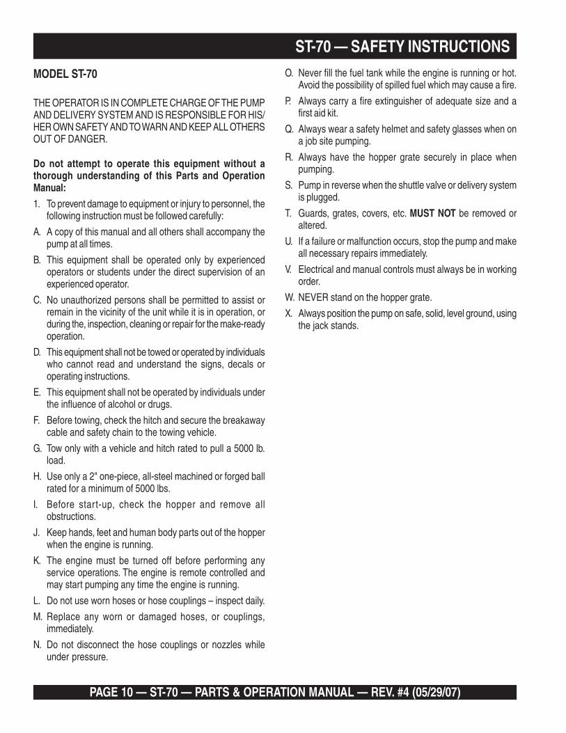
MODEL ST-70
THE OPERATOR IS IN COMPLETE CHARGE OF THE PUMPAND DELIVERY SYSTEM AND IS RESPONSIBLE FOR HIS/HER OWN SAFETY AND TO WARN AND KEEP ALL OTHERSOUT OF DANGER.
Do not attempt to operate this equipment without athorough understanding of this Parts and OperationManual:
1. To prevent damage to equipment or injury to personnel, thefollowing instruction must be followed carefully:
A. A copy of this manual and all others shall accompany thepump at all times.
B. This equipment shall be operated only by experiencedoperators or students under the direct supervision of anexperienced operator.
C. No unauthorized persons shall be permitted to assist orremain in the vicinity of the unit while it is in operation, orduring the, inspection, cleaning or repair for the make-readyoperation.
D. This equipment shall not be towed or operated by individualswho cannot read and understand the signs, decals oroperating instructions.
E. This equipment shall not be operated by individuals underthe influence of alcohol or drugs.
F. Before towing, check the hitch and secure the breakawaycable and safety chain to the towing vehicle.
G. Tow only with a vehicle and hitch rated to pull a 5000 lb.load.
H. Use only a 2" one-piece, all-steel machined or forged ballrated for a minimum of 5000 lbs.
I. Before start-up, check the hopper and remove allobstructions.
J. Keep hands, feet and human body parts out of the hopperwhen the engine is running.
K. The engine must be turned off before performing anyservice operations. The engine is remote controlled andmay start pumping any time the engine is running.
L. Do not use worn hoses or hose couplings – inspect daily.
M. Replace any worn or damaged hoses, or couplings,immediately.
N. Do not disconnect the hose couplings or nozzles whileunder pressure.
ST-70 — SAFETY INSTRUCTIONSO. Never fill the fuel tank while the engine is running or hot.
Avoid the possibility of spilled fuel which may cause a fire.
P. Always carry a fire extinguisher of adequate size and afirst aid kit.
Q. Always wear a safety helmet and safety glasses when ona job site pumping.
R. Always have the hopper grate securely in place whenpumping.
S. Pump in reverse when the shuttle valve or delivery systemis plugged.
T. Guards, grates, covers, etc. MUST NOT be removed oraltered.
U. If a failure or malfunction occurs, stop the pump and makeall necessary repairs immediately.
V. Electrical and manual controls must always be in workingorder.
W. NEVER stand on the hopper grate.
X. Always position the pump on safe, solid, level ground, usingthe jack stands.
ST-70 — PARTS & OPERATION MANUAL — REV. #4 (05/29/07) — PAGE 11
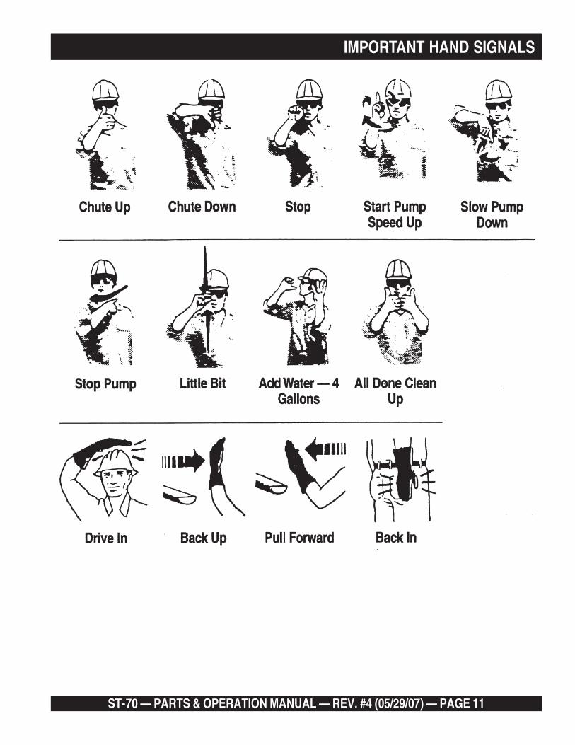
IMPORTANT HAND SIGNALS
PAGE 12 — ST-70 — PARTS & OPERATION MANUAL — REV. #4 (05/29/07)
ST-70 — GENERAL INFORMATION
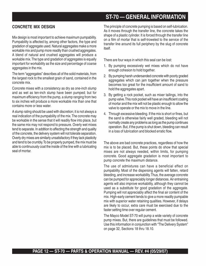
CONCRETE MIX DESIGN
Mix design is most important to achieve maximum pumpability.Pumpability is affected by, among other factors, the type andgradation of aggregate used. Natural aggregates make a moreworkable mix and pump more readily than crushed aggregates.A blend of natural and crushed aggregates will produce aworkable mix. The type and gradation of aggregates is equallyimportant for workability as the size and percentage of coarseaggregates in the mix.
The term “aggregates” describes all of the solid materials, fromthe largest rock to the smallest grain of sand, contained in theconcrete mix.
Concrete mixes with a consistency as dry as one-inch slumpand as wet as ten-inch slump have been pumped; but formaximum efficiency from the pump, a slump ranging from twoto six inches will produce a more workable mix than one thatcontains more or less water.
A slump rating should be used with discretion; it is not always areal indication of the pumpability of the mix. The concrete maybe workable in the sense that it will readily flow into place, butthe same mix may not respond to pressure. Overly wet mixestend to separate. In addition to affecting the strength and qualityof the concrete, the delivery system will not tolerate separation.Overly dry mixes are similarly unsatisfactory if they lack plasticityand tend to be crumbly. To be properly pumped, the mix must beable to continuously coat the inside of the line with a lubricatingseal of mortar.
The principle of concrete pumping is based on self-lubrication.As it moves through the transfer line, the concrete takes theshape of a plastic cylinder. It is forced through the transfer lineon a film of mortar that is self-troweled to the service of thetransfer line around its full periphery by the slug of concreteitself.
There are four ways in which this seal can be lost:
1. By pumping excessively wet mixes which do not haveenough cohesion to hold together.
2. By pumping harsh undersanded concrete with poorly gradedaggregates which can jam together when the pressurebecomes too great for the insufficient amount of sand tohold the aggregates apart.
3. By getting a rock pocket, such as mixer tailings, into thepump valve. This rock pocket will have an insufficient coatingof mortar and the mix will not be plastic enough to allow thevalve to operate or the mix to move in the line.
4. Through excessive bleeding. If the mix is short or fines, butthe sand is otherwise fairly well graded, bleeding will notnormally create any problems as long as the pump continuesoperation. But, if the pump is shut down, bleeding can resultin a loss of lubrication and blocked erratic flow.
The above are bad concrete practices, regardless of how themix is to be placed. But, these points do show that specialmixes are not always needed, within limits, for pumpingconcrete. Good aggregate gradation is most important topump concrete the maximum distance.
The use of admixtures can have a beneficial effect onpumpability. Most of the dispersing agents will fatten, retardbleeding, and increase workability. Thus, the average concretecan be pumped for appreciably longer distances. Air entrainingagents will also improve workability, although they cannot beused as a substitute for good gradation of the aggregate.Pumping will not appreciably affect the final air content of themix. High-early cement tends to give a more readily pumpablemix with superior water retaining qualities. However, if delaysare likely to occur, extra care must be exercised due to thefaster setting time over regular cement.
The Mayco Model ST-70 will pump a wide variety of concretepump mixes. But, there are guidelines that must be followed.Use this information in conjunction with “The Delivery System”on page 32, Sections 18 thru 18.10.

ST-70 — PARTS & OPERATION MANUAL — REV. #4 (05/29/07) — PAGE 13
ST-70 — GENERAL INFORMATION
REGIONAL DIFFERENCES
Concrete is made by mixing locally available rock and sandwith cement and water. For this reason there are greatdifferences in the pumpability of concrete from one region ofthe country to another.
It is impossible to define a specific mix for each region that theModel ST-70 be will working in. Therefore, the mixes on pages14 through 17 will provide a basic guideline for establishingthe proper mix design for your area.
Use this information to specify your requirements to your localready-mix batch plant, contractor and civil engineer. It may takeminor adjustments to make a mix pumpable, so you shouldexplain your needs.
The elements that have to be controlled and consistentlymaintained by the batch plant are:
1. The sizing and mix percentage of rocks, gap graded fromthe largest down through the smallest sizes.
2. Sand with a sieve analysis that has the proper percentageof fines, ASTM C33 spec.
3. Sufficient cement to produce the required design strengthof the concrete and provide the lubricating binder to pumpthe concrete through the delivery system.
Use a minimum of:
500 lbs. of cement/cu yd for 2500 p.s.i. concreteafter 28 days.
530 lbs. of cement/cu yd for 3000 p.s.i. concreteafter 28 days.
600 lbs. of cement/cu yd for 4000 p.s.i. concreteafter 28 days.
4. Admixture pump-aid if necessary.
5. The proper amount of water to make a workable slumpand plasticize the mix.
In addition, the Mayco Structural Concrete ST-70 Pump can beused to pump a large aggregate hard rock as follows:
1. Pea rock (1/2" minus) pump with mixes being as low as30% rock and 70% sand. (See page 30, for comments oncleaning the pump.)
2. Shortening pea rock when used with an air compressorand nozzle. (See back pages for recommended set-up.)
3. “Mud Jacking”, high pressure grouting.

PAGE 14 — ST-70 — PARTS & OPERATION MANUAL — REV. #4 (05/29/07)
ST-70 — CONCRETE MIX INFORMATIONJob Identification* _______________________________________ Date* ______________________________________
Architect* ______________________________________________ General Contractor* ___________________________
Structural Engineer* ______________________________________ Concrete by* ________________________________
THE PROPORTIONS SHOWN HERE ARE A RECOMMENDATION BASED ON TESTS OF SAMPLES RECEIVED BY THELABORATORY. TESTS PERFORMED BY SUPPLIERS OR MANUFACTURERS OR ON PRIOR KNOWLEDGE OF THEMATERIALS INVOLVED AND IS LIMITED TO INFORMATION DERIVED FROM THESE SAMPLES TESTS BY OTHERS ORTO THAT PRIOR KNOWLEDGE.
IT IS UNDERSTOOD THAT THE CHEMICAL AND/OR PHYSICAL CHARACTERISTICS OF THESE MATERIALS ARESUBJECT TO VARIATIONS THAT MAY ADVERSELY AFFECT THE FINISHED PRODUCT AND THAT THIS MIX DESIGN ISNOT TO BE USED EXCEPT AT THE USERS OWN RISK UNLESS THESE VARIATIONS ARE DETERMINED ANDCOMPENSATED FOR IN A MANNER APPROVED BY THE LABORATORY IN WRITING.
Specifications requirements: 2500 P.S.I. in 28 DAYS 3" SLUMP PUMP MIX 4" DIA LINE
SIEVE ANALYSIS PER CENT PASSING U.S. STANDARD SIEVE
MATERIAL ......... 1 1/2 ............ 1 ............... 3/4 ..................................................................................................................FAI WCS ....................................................................... 100 ........ 97 ............ 84 ........... 70 ....... 45 ........25 ..... 10 ....... 97.5FA2 ...................................................................................................................................................................................CA1 #4-3/8" .............................................. 100 ............. 95 .......... 13 ............ 3 ............................................................... 90.5CA2 #3-1 ................................ 100 ........... 96 ............... 61 .......... 6 .............. 1 ............................................................... 91.0CA3 ................................................................................................................................................................................................................................. 100 ........... 98 ............... 85 .......... 50 ............ 40 ........... 33 ....... 21 ........12 ..... 4 .........
Source of Coarse & Fine Aggregates -* Cement – Type* Mix No*
Cement Sks/Cu. Yd. ................................................................ 5.3Cement – Lbs. ........................................................................ 500Sand, Lbs. W.C.S. ................................................................... 1550No. 4 Gravel (3/8"), Lbs. .......................................................... 500No. 3 Gravel (1"), Lbs. ............................................................. 1220No. 2 Gravel (1-1/2"), Lbs. .......................................................Water, Lbs. .............................................................................. 290 Total Weight ........................................................................... 4060Water, gal. per yd. ................................................................... 34.8Water, gal./Sk. per yd. ............................................................. 6.5Slump, calculated ................................................................... 3"Admixture ............................................................................... 3 fl. oz. POZZOLITH 300N/100 * OF CEMENTMax. Water Allowable ............................................................. ** THIS INFORMATION PROVIDED BY ENGINEER OR BATCH PLANTTHE ABOVE MIX DESIGN IS TYPICAL OF A PUMPABLE MIX. TO BE USED AS A GUIDELINE ONLY. REFER TO LOCALAGENCY FOR JOB SPECIFICATION.
3-5

ST-70 — PARTS & OPERATION MANUAL — REV. #4 (05/29/07) — PAGE 15
ST-70 — CONCRETE MIX INFORMATIONJob Identification* _______________________________________ Date* ______________________________________
Architect* ______________________________________________ General Contractor* ___________________________
Structural Engineer* _____________________________________ Concrete by* ________________________________
THE PROPORTIONS SHOWN HERE ARE A RECOMMENDATION BASED ON TESTS OF SAMPLES RECEIVED BY THELABORATORY. TESTS PERFORMED BY SUPPLIERS OR MANUFACTURERS OR ON PRIOR KNOWLEDGE OF THEMATERIALS INVOLVED AND IS LIMITED TO INFORMATION DERIVED FROM THESE SAMPLES TESTS BY OTHERS ORTO THAT PRIOR KNOWLEDGE.
IT IS UNDERSTOOD THAT THE CHEMICAL AND/OR PHYSICAL CHARACTERISTICS OF THESE MATERIALS ARESUBJECT TO VARIATIONS THAT MAY ADVERSELY AFFECT THE FINISHED PRODUCT AND THAT THIS MIX DESIGN ISNOT TO BE USED EXCEPT AT THE USERS OWN RISK UNLESS THESE VARIATIONS ARE DETERMINED ANDCOMPENSATED FOR IN A MANNER APPROVED BY THE LABORATORY IN WRITING.
Specifications requirements: 3000 P.S.I. in 28 DAYS 4" SLUMP PUMP MIX 4" DIA LINE
SIEVE ANALYSIS PER CENT PASSING U.S. STANDARD SIEVE
MATERIAL ......... 1 1/2 ............ 1 ............... 3/4 ..................................................................................................................FAI WCS ....................................................................... 100 ........ 98 ............ 86 ........... 70 ....... 48 ........24 ..... 8 ......... 97.5FA2 ...................................................................................................................................................................................CA1 #4-3/8" .............................................. 100 ............. 94 .......... 16 ............ 4 ............................................................... 90.5CA2 #3-1 ................................ 100 ........... 93 ............... 57 .......... 6 .............. 1 ............................................................... 91.0CA3 ................................................................................................................................................................................................................................. 100 ........... 97 ............... 83 .......... 51 ............ 41 ........... 33 ....... 23 ........11 ..... 4 .........
Source of Coarse & Fine Aggregates -* Cement – Type* Mix No*
Cement Sks/Cu. Yd. ................................................................ 5.Cement – Lbs. ........................................................................ 525Sand, Lbs. W.C.S. ................................................................... 1520No. 4 Gravel (3/8"), Lbs. .......................................................... 480No. 3 Gravel (1"), Lbs. ............................................................. 1230No. 2 Gravel (1-1/2"), Lbs. .......................................................Water, Lbs. .............................................................................. 295 Total Weight .................................................................... 4050Water, gal. per yd. ................................................................... 35.4Water, gal./Sk. per yd. ............................................................. 6.3Slump, calculated ................................................................... 4"Admixture ............................................................................... 3 fl. oz. POZZOLITH 300N/100 * OF CEMENTMax. Water Allowable ............................................................. ** THIS INFORMATION PROVIDED BY ENGINEER OR BATCH PLANTTHE ABOVE MIX DESIGN IS TYPICAL OF A PUMPABLE MIX. TO BE USED AS A GUIDELINE ONLY. REFER TO LOCALAGENCY FOR JOB SPECIFICATION.
PAGE 16 — ST-70 — PARTS & OPERATION MANUAL — REV. #4 (05/29/07)
ST-70 — CONCRETE MIX INFORMATIONJob Identification* _______________________________________ Date* ______________________________________
Architect* ______________________________________________ General Contractor* ___________________________
Structural Engineer* _____________________________________ Concrete by* ________________________________
THE PROPORTIONS SHOWN HERE ARE A RECOMMENDATION BASED ON TESTS OF SAMPLES RECEIVED BY THELABORATORY. TESTS PERFORMED BY SUPPLIERS OR MANUFACTURERS OR ON PRIOR KNOWLEDGE OF THEMATERIALS INVOLVED AND IS LIMITED TO INFORMATION DERIVED FROM THESE SAMPLES TESTS BY OTHERS ORTO THAT PRIOR KNOWLEDGE.
IT IS UNDERSTOOD THAT THE CHEMICAL AND/OR PHYSICAL CHARACTERISTICS OF THESE MATERIALS ARESUBJECT TO VARIATIONS THAT MAY ADVERSELY AFFECT THE FINISHED PRODUCT AND THAT THIS MIX DESIGN ISNOT TO BE USED EXCEPT AT THE USERS OWN RISK UNLESS THESE VARIATIONS ARE DETERMINED ANDCOMPENSATED FOR IN A MANNER APPROVED BY THE LABORATORY IN WRITING.
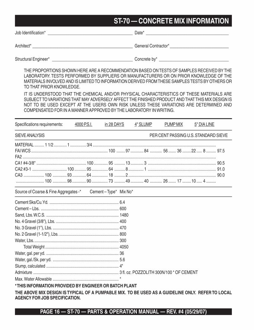
Specifications requirements: 4000 P.S.I. in 28 DAYS 4" SLUMP PUMP MIX 5" DIA LINE
SIEVE ANALYSIS PER CENT PASSING U.S. STANDARD SIEVE
MATERIAL ......... 1 1/2 ............ 1 ............... 3/4 ..................................................................................................................FAI WCS ....................................................................... 100 ........ 97 ............ 84 ........... 56 ....... 36 ........22 ..... 8 ......... 97.5FA2 ...................................................................................................................................................................................CA1 #4-3/8" .............................................. 100 ............. 95 .......... 13 ............ 3 ............................................................... 90.5CA2 #3-1 ................................ 100 ........... 95 ............... 64 .......... 8 .............. 1 ............................................................... 91.0CA3 ................... 100 ............. 93 ............. 64 ............... 18 .......... 2 ................................................................................. 90.0.......................... 100 ............. 98 ............. 90 ............... 73 .......... 49 ............ 40 ........... 26 ....... 17 ........10 ..... 4 .........
Source of Coarse & Fine Aggregates -* Cement – Type* Mix No*
Cement Sks/Cu. Yd. ................................................................ 6.4Cement – Lbs. ........................................................................ 600Sand, Lbs. W.C.S. ................................................................... 1480No. 4 Gravel (3/8"), Lbs. .......................................................... 400No. 3 Gravel (1"), Lbs. ............................................................. 470No. 2 Gravel (1-1/2"), Lbs. ....................................................... 800Water, Lbs. .............................................................................. 300 Total Weight .................................................................... 4050Water, gal. per yd. ................................................................... 36Water, gal./Sk. per yd. ............................................................. 5.6Slump, calculated ................................................................... 4"Admixture ............................................................................... 3 fl. oz. POZZOLITH 300N/100 * OF CEMENTMax. Water Allowable ............................................................. ** THIS INFORMATION PROVIDED BY ENGINEER OR BATCH PLANTTHE ABOVE MIX DESIGN IS TYPICAL OF A PUMPABLE MIX. TO BE USED AS A GUIDELINE ONLY. REFER TO LOCALAGENCY FOR JOB SPECIFICATION.

ST-70 — PARTS & OPERATION MANUAL — REV. #4 (05/29/07) — PAGE 17
ST-70 — CONCRETE MIX INFORMATION
The sand content of pumpable concrete is very important. It isone of the two major ingredients that change due to regionallocation (the other is the rock or gravel).
Above is a typical sieve analysis of washed concrete sand(W.C.S.) to A.S.T.M. C33 specifications.
The total of the “Accumulated % Retained” is the FinenessModulus (F.M.). The ideal F.M. is between 2.50 and 2.75, but thecorrect F.M. does not guarantee pumpability. Besides having acorrect F.M. the percentage of sand by weight that passes throughthe No. 50 sieve must be between 15 and 30 and through theNo. 100 sieve 5 and 10. The total of #50 and 100 mesh particlesmust be between 25 and 35 percent.
This fine material plus the cement will provide the necessaryfilm of lubrication to move the concrete inside the delivery system.
DNASETERCNOC—SISYLANAEVEIS
EZISEVEIS33CMTSA
SCEPSSSAP%MUCCA
1#ELPMAS%VIDNI
TER
4# 001-59 89 2 2
8 001-08 98 11 9
61 58-05 17 92 81
03 06-52 74 35 42
05 03-01 32 77 42
001 01-2 7 39 61
002
56.2=.M.FsuludoMsseneniF 56.2

PAGE 18 — ST-70 — PARTS & OPERATION MANUAL — REV. #4 (05/29/07)
1. To obtain a representative sample, take samples at three ormore regular intervals throughout the discharge of the mixeror truck. DO NOT take samples at the beginning or end of thedischarge.
2. Dampen the inside of the cone and place it on a smooth,moist, nonabsorbent, level surface large enough toaccommodate both the slumped concrete and the slump cone.Stand on the “foot pieces” throughout the test procedure tohold the cone firmly in place.
3. Fill the cone !/3 full by volume and rod 25 times with a 1/2"dia x 24" lg. bullet-pointed steel rod. (This is a specificrequirement which will produce non-standard results unlessfollowed exactly.) Distribute rodding evenly over the entire crosssection of the sample. (See figure A.)
4. Fill cone another !/3 which will make the cone @/3 full byvolume. Rod this second layer 25 times with the rod penetratinginto, but not through, the first layer. Distribute rodding evenlyover the entire cross section of the layer. (See figure B.)
5. Fill cone to overflowing. Rod this layer 25 times with rodpenetrating into but not through, the second layer. Distributerodding evenly over the entire cross section of this layer. (Seefigure C.)
6. Remove the excess concrete from the top of the cone, usingthe tamping rod as a screed. (See figure D.)
7. Lift the cone vertically with a slow even motion. Do not jarthe concrete or tilt the cone during this process. (See figureE.) Invert the withdrawn cone, and place it next to, but nottouching the slumped concrete.
8. Lay a straight edge across the top of the slumped cone.Measure the amount of slump in inches from the bottom ofthe straight edge to the top of the slumped concrete at a pointover the original center of the base (See Figure F). The slumpoperation must be complete in a maximum elapsed time of 1-½ minutes. Discard the concrete. DO NOT use it in any othertests.
SLUMP TEST PROCEDURE
ST-70 — PARTS & OPERATION MANUAL — REV. #4 (05/29/07) — PAGE 19
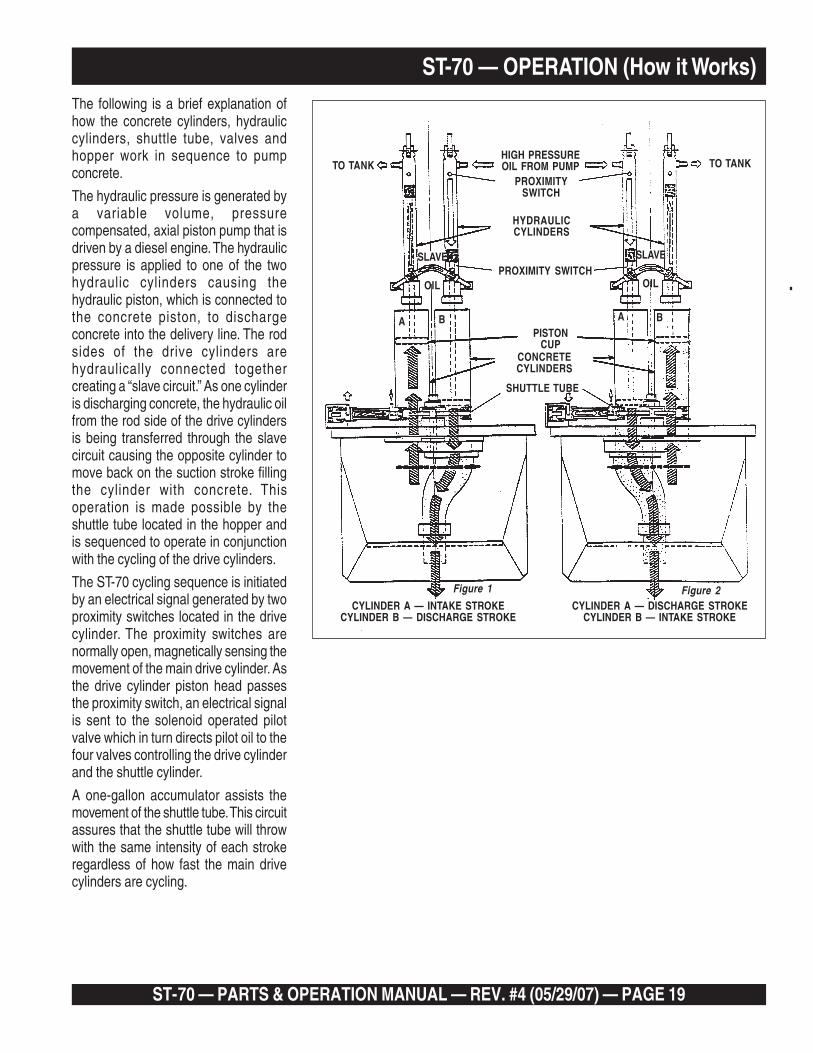
ST-70 — OPERATION (How it Works)The following is a brief explanation ofhow the concrete cylinders, hydrauliccylinders, shuttle tube, valves andhopper work in sequence to pumpconcrete.
The hydraulic pressure is generated bya variable volume, pressurecompensated, axial piston pump that isdriven by a diesel engine. The hydraulicpressure is applied to one of the twohydraulic cylinders causing thehydraulic piston, which is connected tothe concrete piston, to dischargeconcrete into the delivery line. The rodsides of the drive cylinders arehydraulically connected togethercreating a “slave circuit.” As one cylinderis discharging concrete, the hydraulic oilfrom the rod side of the drive cylindersis being transferred through the slavecircuit causing the opposite cylinder tomove back on the suction stroke fillingthe cylinder with concrete. Thisoperation is made possible by theshuttle tube located in the hopper andis sequenced to operate in conjunctionwith the cycling of the drive cylinders.
The ST-70 cycling sequence is initiatedby an electrical signal generated by twoproximity switches located in the drivecylinder. The proximity switches arenormally open, magnetically sensing themovement of the main drive cylinder. Asthe drive cylinder piston head passesthe proximity switch, an electrical signalis sent to the solenoid operated pilotvalve which in turn directs pilot oil to thefour valves controlling the drive cylinderand the shuttle cylinder.
A one-gallon accumulator assists themovement of the shuttle tube. This circuitassures that the shuttle tube will throwwith the same intensity of each strokeregardless of how fast the main drivecylinders are cycling.
TO TANKHIGH PRESSUREOIL FROM PUMP TO TANK
HYDRAULICCYLINDERS
PISTONCUP
CONCRETECYLINDERS
SLAVE
OIL
SLAVE
OIL
A AB B
Figure 1
CYLINDER A — INTAKE STROKECYLINDER B — DISCHARGE STROKE
CYLINDER A — DISCHARGE STROKECYLINDER B — INTAKE STROKE
Figure 2
PROXIMITY SWITCH
PROXIMITYSWITCH
SHUTTLE TUBE

PAGE 20 — ST-70 — PARTS & OPERATION MANUAL — REV. #4 (05/29/07)
This section is intended to assist the operator with the initialstart-up of the MAYCO ST-70 Concrete Pump. It is extremelyimportant that this section be read carefully before attemptingto use the pump in the field.
DO NOT proceed to the Operating Procedures (field use) ofthis manual until this section is thoroughly understood.
NOTE:
Failure to understand the operation of the MAYCO ST-70Concrete pump could result in severe damage to the pump orpersonal injury.
Figure 1 illustrates the basic operating controls and indicatorson the MAYCO ST-70 Concrete pump. Each of the itemsreferenced will be discussed. The sequence will be as follows:
1. Engine Oil
2. Hydraulic Oil
3. Fuel
4. Rear Stabilizer Stands
5. Emergency Stop Switch
6. Ignition Switch
7. Status Indicators
8. Control Switch, Engine Throttle Control
9. Volume Control
10. Engine Speed, Cooling Fan
11. Pressure Test
12. Hopper Remixer Control Lever
13. Manual and Radio Control
14. Cylinder Lubrication
INITIAL START-UP PROCEDURE
Figure 1. MAYCO ST–70Controls and Indicators
ST-70 — PARTS & OPERATION MANUAL — REV. #4 (05/29/07) — PAGE 21
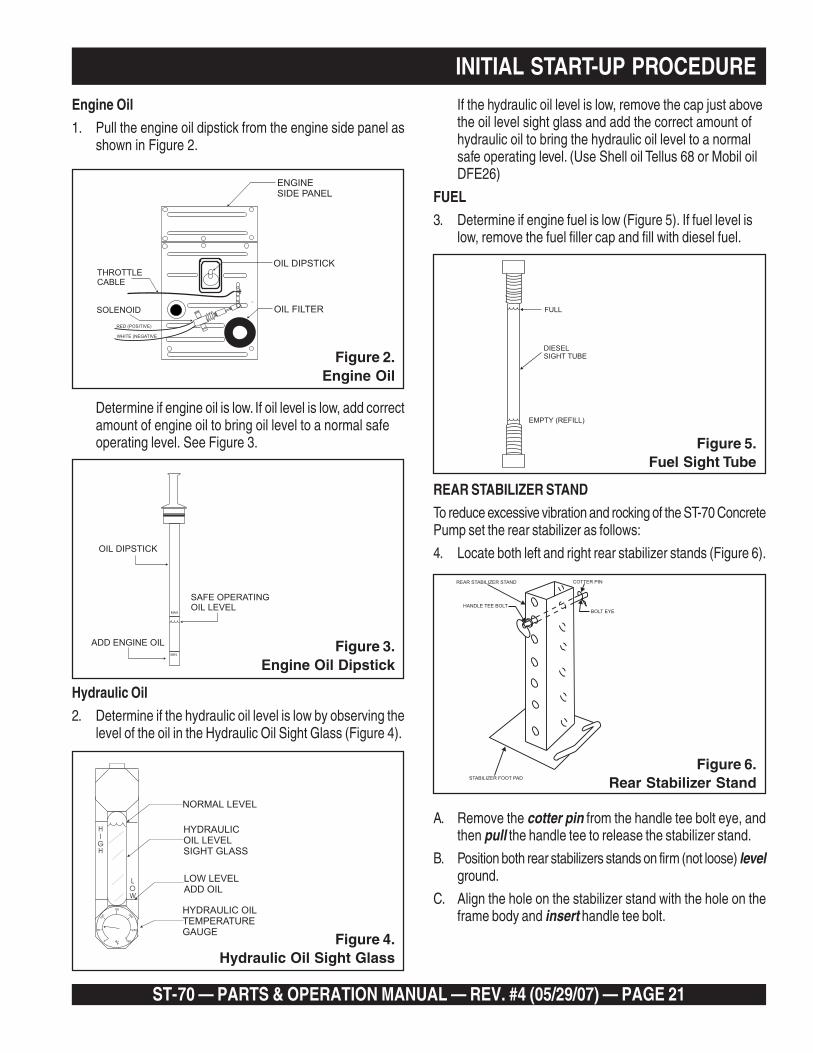
Engine Oil
1. Pull the engine oil dipstick from the engine side panel asshown in Figure 2.
Determine if engine oil is low. If oil level is low, add correctamount of engine oil to bring oil level to a normal safeoperating level. See Figure 3.
If the hydraulic oil level is low, remove the cap just abovethe oil level sight glass and add the correct amount ofhydraulic oil to bring the hydraulic oil level to a normalsafe operating level. (Use Shell oil Tellus 68 or Mobil oilDFE26)
FUEL
3. Determine if engine fuel is low (Figure 5). If fuel level islow, remove the fuel filler cap and fill with diesel fuel.
Figure 3.Engine Oil Dipstick
MAX
MIN
ADD ENGINE OIL
SAFE OPERATINGOIL LEVEL
OIL DIPSTICK
Figure 4.Hydraulic Oil Sight Glass
150
200
250
150
100
50
0F
H
L
I
O
G
W
H
HYDRAULICOIL LEVELSIGHT GLASS
NORMAL LEVEL
LOW LEVELADD OIL
HYDRAULIC OILTEMPERATUREGAUGE
OIL DIPSTICK
OIL FILTER
THROTTLECABLE
SOLENOID
ENGINESIDE PANEL
RED (POSITIVE)
WHITE (NEGATIVE
Figure 2.Engine Oil
INITIAL START-UP PROCEDURE
Hydraulic Oil
2. Determine if the hydraulic oil level is low by observing thelevel of the oil in the Hydraulic Oil Sight Glass (Figure 4).
REAR STABILIZER STAND
To reduce excessive vibration and rocking of the ST-70 ConcretePump set the rear stabilizer as follows:
4. Locate both left and right rear stabilizer stands (Figure 6).
Figure 6.Rear Stabilizer Stand
COTTER PIN
BOLT EYE
REAR STABILIZER STAND
HANDLE TEE BOLT
STABILIZER FOOT PAD
A. Remove the cotter pin from the handle tee bolt eye, andthen pull the handle tee to release the stabilizer stand.
B. Position both rear stabilizers stands on firm (not loose) levelground.
C. Align the hole on the stabilizer stand with the hole on theframe body and insert handle tee bolt.
Figure 5.Fuel Sight Tube

PAGE 22 — ST-70 — PARTS & OPERATION MANUAL — REV. #4 (05/29/07)
Figure 10.Control Off Switch
CONTROL
OFF
ON REMOTE
D. Insert the cotter pin into handle tee bolt eye to lock thestabilizer stand.
Emergency Stop Switch
5. Locate the Emergency Stop Switch (Figure 7) on theHydraulic Pump Control Box. Use this switch in the event ofa emergency.
NOTE:
If the Emergency Stop switch is in the closed position (stop),engine will not start. To start the engine, make sure theEmergency Stop switch is in the open position (fully extended).
Ignition Switch
NOTE:
Place all switches on the Hydraulic Control Box in the verticalposition (up).
6. To start the engine, insert the key (Figure 8) into the ignitionswitch and turn the key to the ON position.
Turn the Emergency Stop switch counter-clockwise (open).This will allow the engine to start.
Figure 7.Emergency Stop
Switch
EMERGENCY
S TOP
Figure 8.Ignition Switch
IGNITION
ON
OFF START
BATTERYOILAIR FILTER
PRESSURE
Figure 9.Status indicator Lights
INITIAL START-UP PROCEDURE7. Observe that the Air Filter and Oil Pressure status indicator
lights are ON (Figure 9). The Battery status indicator lightshould be OFF
A. Turn the key to the START position and listen for the engineto start.
B. In warm weather let engine warm-up for 5 minutes. In coldweather let engine warm-up for 10 minutes.
C. The Air Filter, Oil Pressure and Battery indicator lights(Figure 9) should all be off.
NOTE:
If any of the status indicator lights referenced in the ignitionsection (step 4) are ON, turn off the engine. DO NOT continueto run the engine.
Control Switch
8. Turn the Control Off switch (Figure 10) to the ON position,a thumping sound (cylinder stroke) should be heard. Thethumping sound represents the number of strokes perminute (volume) of the pump.

ST-70 — PARTS & OPERATION MANUAL — REV. #4 (05/29/07) — PAGE 23
A. Use the volume control, to set the pump volume toapproximately 10 strokes per minute. Turning the volumecontrol clockwise (CW) will decrease pump volume, andcounterclockwise (CCW) will increase pump volume.
NOTE:
Use a wristwatch or stop watch to determine the number ofpump strokes within 1 minute.
B. Let the pump cycle until the hydraulic oil temperature(Figure 12) is approximately 50 to 60 degrees fahrenheit.
C. While monitoring the tachometer, (Figure 13) turn theengine Throttle Control (Figure 14) until the engine speedreaches 1500 RPM.
D. Turn the Control Off switch (Figure 10) to the OFF position.
Figure 13.Engine Tachometer
2025
3010
40TACH
HOURS
RPM X 100
81
10
0
355
15
0 0 0 0 4
Figure 12. Hydraulic OilTemperature Gauge
150
200
250
150
100
50
0F
Figure 14.Engine Throttle Control
THROTTLECONTROL
TURN CLOCKWISE TOINCREASE ENGINE SPEED
TURN COUNTER CLOCKWISETO DECREASE ENGINE SPEED
INITIAL START-UP PROCEDURE
9. Turn the Volume Control (Figure 11), lock nutcounterclockwise (CCW) to release the volume controlknob.
Figure 11.Volume Control
3C
3A
VOLUME CONTROL
DECREASEINCREASE
CCW CW
VOLUME CONTROLLOCK NUT
Engine Speed
10. Turn the Operation Pump/Engine switch to the engineposition (Figure 15).
NOTE:
The pump should not be cycling at this time. Only the ENGINEshould be running.
Figure 15. OperationPump/Engine Switch
OPERATION
PUMP
ENGINE

PAGE 24 — ST-70 — PARTS & OPERATION MANUAL — REV. #4 (05/29/07)
13. HOPPER REMIXER CONTROL
A. Located to the left of the Hydraulic Temperature gauge isthe Hopper Remixer Control lever (Figure 19).
B. Turn the Operation Pump/Engine switch to the engineposition (only the engine should be running).
Figure 19.Hopper Remixer
Control Lever
PUSH DOWNTO OPERATE(CW BLADEROTATION)
PUSH UP TOREVERSE BLADEROTATION (CCW)
A. While monitoring the tachometer, (Figure 13) turn theengine Throttle Control (Figure 14) clockwise until theengine speed reaches 2550 RPM (maximum speed).
B. The Accumulator Pressure Gauge (Figure 16) should readapproximately 1750 pounds per square inch (psi).
Turn the Fan switch to the OFF position and listen for fan tostop. If machine exceeds 170°F, and to cool the machine down,turn operation switch to (Fig. 15) engine position. Run engine athigh RPM with cooling fan on for 10 to 15 minutes.
NOTE: Do not stroke cylinders. The operator may also spraythe hydraulic tank and components with water.
Figure 16. AccumulatorPressure Gauge
ACCUMULATORPRESSURE GAUGE
0-3000 PSI
2000
3000
1500
LHA0
2500500
1000
Figure 17.Fan On/Off Switch
FANOFF
ON
PRESSURE TEST
12. The Pressure Test switch (Figure 18) is a self-diagnostictest switch, that when activated will test the pressure of thesystem. This switch will be discussed in the maintenanceand troubleshooting section of this manual.
Figure 18.Pressure Test On/Off Switch
PRESS TEST
OFFON
INITIAL START-UP PROCEDURE
11. COOLING FAN
CAUTION
If the hydraulic oil temperature exceeds 170 degrees fahrenheit,shut down the pump. DO NOT continue to operate the pump.Failure to shut down the pump will result in severe damage tothe pump.
This section is intended to make sure the Fan is working properly.Under normal conditions the Fan should be turned on when thehydraulic oil temperature begins to approach between 75degrees fahrenheit.
Make sure the Operation Pump/Engine switch is in the engineposition (Figure 15), and that only the engine is running.
Turn the Fan switch (Figure 17) to the ON position and listen forfan to start.

ST-70 — PARTS & OPERATION MANUAL — REV. #4 (05/29/07) — PAGE 25
D. Push the Hopper Remixer Control lever upward (Figure18) and observe that the blades (Figure 20) inside thehopper are turning in a counter-clockwise direction(reverse).
14. OPTIONAL RADIO REMOTE CONTROL
The MAYCO ST-70 Concrete Pump has a remote control featurethat allows the pump to be remotely controlled. If desired, thepump can be operated via a receiver/transmitter method (Figure21) or a hardwire method, which utilizes a 25-ft. extension cable.The manual remote cord (Figure 22) should be installed underthe main control box. Contact your MAYCO representative forfurther information.
C. Push the Hopper Remixer Control lever downward (Figure19) and observe that the blades (Figure 20) inside thehopper are turning in a clockwise direction (forward).
Figure 20.Hopper Remixer
Blades (Rotation)
FORWARD
REVERSE
SHAFT ROTATION
BLADES
(CCW)
(CW)
INITIAL START-UP PROCEDURE
Figure 21. Handheld Receiver/
Transmitter
REMTRON
REMTRON
ON ON
OFF OFF
A B
HANDHELD
REMOTE CONTROL TRANSMITTERREMOTE CONTROL TRANSMITTER
REMOTE CONTROL RECEIVERREMOTE CONTROL RECEIVER
ANTENNAINPUTANTENNAINPUT
CONTROL SWITCHESCONTROL SWITCHES
MOUNT ON MAYCO ST-45FRAME BODYMOUNT ON MAYCO ST-45FRAME BODY
SIGNALCABLESIGNALCABLE
Figure 22.Handheld Remote Cable Unit
HAND HELDREMOTE UNITHAND HELDREMOTE UNIT
CONTROL SWITCHESCONTROL SWITCHES
25 FT. CABLE25 FT. CABLE
15. CYLINDER LUBRICATION BOX
WARNING
Before checking lubricaton level, stop theengine and remove the engine starter key. Werecommend using soluble type oil (water & oilmixture). The oil level should be checked
everyday prior to pumping. The oil level should be maintainedat a height of 5 inches or about ́ ½ the concrete cylinder height.
Important Notice! During freezing temperature after pumping,completely drain the water box and cover the hopper. Frozenliquid will restrict the piston travel and cause severe damage tothe pump.
As the rubber piston cups naturally wear, fine cement particleswill accumulate in the box. Once the concrete paste reaches aheight of about ½ inch from the bottom. The box should bedrained and cleaned. To clean, remove the drain plug locatedat the bottom of the box. Once the Box is drained, start theengine and stroke the cylinder (keep hands out of box) ten tofifteen times. While stroking, spray water inside of the box tothoroughly clean out all contamination. When the box is clean,replace drain plug, add new lubrication and install the top cover.
Any questions regarding the above mentioned procedure,please call the Mayco Service Department: 1-800-30-MAYCO.

PAGE 26 — ST-70 — PARTS & OPERATION MANUAL — REV. #4 (05/29/07)
14. Vertical and down-hill pumping are more difficult thanhorizontal pumping. Vertical pumping requires higherpumping pressure. Down-hill pumping can causeseparation of the concrete, which can cause a blockage.Back pressure must be kept in the line at all times duringdown-hill pumping.
15. When the pump is parked in the street, position it so that thecontrol panel (right side) is closest to the curb. – ALWAYSTHINK SAFETY!
16. Lower and lock the rear jackstands in place before anyconcrete is discharged into the hopper.
17.THE DELIVERY SYSTEM
To successfully pump concrete it is critical to use the correctsize and type of delivery system.
The rules that govern the size of the delivery system applyto all concrete pumps, not just Mayco pumps.
The inside diameter of the hose and pipe must be three tofour (3 to 4) times the size of the largest aggregate in the mixthat is to be pumped.
Example:
1-1/2" rock (8 to 10% max. content by weight) requiresa 5" dia. concrete delivery system.
1" rock (10 to 15% max. content by weight) requires a4" dia. concrete delivery system.
¾" and under rock (10 to 15% max. content by weight)requires a 3" dia. concrete delivery system.
The rock size and percentage shown is of the total rock contentin the mix. The balance of the rock must be properly blendeddown through all of the smaller sizes.
The same applies to the sand portion of the mix.
Consult the ready-mix company and ensure that they are willingand able to deliver properly blended aggregates in theirconcrete. 3" inside diameter is the smallest system of hose,pipe and elbows that is recommended for pumping “Hard Rock”,large aggregate concrete.
Remember – The larger the size of the delivery system, the lesspressure required to move the concrete.
Use this information in conjunction with “Concrete Mix Design”on pages 12 thru 17.
Important Rules for the Setup and Operation of
Mayco Model ST-70 Hydraulic Concrete Pump
1. The Mayco pump must be operated by experiencedoperators, who are qualified with the particular model beingused, or students under the direct supervision of anexperienced operator. The operator is in complete chargeof the pump and delivery system. Know and warn all othersof the DANGERS that are present when using, maintainingor being around this pump and delivery system. KNOWYOUR MACHINE!
2. The operator must become familiar with the controls andgauges by a careful study of the owners manual.
3. The operator must become aware and understand thedanger involved in the operation and maintenance of thepump.
4. The operator must know the limitation of the pump describedin this manual.
5. The concrete pump is capable of developing high pressureson the concrete. Proper care must be used in themaintenance of pipes and hoses and hose couplings forsafe operation.
6. Only experienced operators, or students under the directsupervision of an experienced operator shall perform anymaintenance, cleaning, repair or setup operations.
7. Unauthorized persons must not be permitted to assist orremain in the immediate vicinity of the unit while it is inoperation.
8. The Mayco pump must not be operated by individuals whocannot read and understand the owners manual in thelanguage in which it is printed.
9. The Mayco pump must not be operated by anyone underthe age of 18 years.
10. The Mayco pump must not be operated by anyone underthe influence of alcohol or drugs.
11. Locate the pump in an area as level as possible, where twoor more ready-mix trucks will have access to the hopper.
12. Begin pumping by placing the hoses or pipe at the farthestpoint of discharge.
13.Concrete will flow with less back pressure through pipethan through hose. Bends in hose or pipe will also requiremore pressure. The operator should take these facts intoconsideration when laying out the system.
ST-70 — OPERATING PROCEDURES

ST-70 — PARTS & OPERATION MANUAL — REV. #4 (05/29/07) — PAGE 27
ST-70 — OPERATING PROCEDURES
WARNING: Common sense tells us that if youdrive a truck into a “brick wall,” something isgoing to be damaged. The same holds truewith your concrete pump. If you repeatedly pullthe throttle all the way out and force your pump
to push through blockages due to separation of material in thehose or manifold, you will soon have breakdowns and costlyrepairs which are not covered under the warranty. If a blockageexists, find where it is and clear it before further pumping. Donot use extra horse power, it will only make it worse.
1. When pumping long distances or pumping stiff mixes, youcan expect a drop in volume, compared to shorter lines andwetter mixes due to higher pumping pressures andcavitation.
2. Leaking hose coupling gaskets (which leak water) causeseparation and subsequent jamming at that point.
18 Priming the Pump and Delivery System with Slurry.
It is CRITICAL to the successful operation of a concretepump that the manifold and all delivery hose, pipe andelbows are coated with a film of lubrication BEFOREyou attempt to pump concrete. Failure to properlyprepare the pump and system will result in a “dry pack”of concrete, blocking the shuttle valve tube or deliveryline.
18.1 With the entire delivery system connected to the pump.Except for the first hose. Pour 5 gallons of water into thesecond hose and push in your clean out ball andreconnect. This will help hold back the prime.
18.2 What you can use to mix the prime:
There are several things you can use for the prime. Hereare a few. Cement and lime at a 50/50 mixture, slick pac,bentonite clay.
NOTE: The bentonite is not compatible with concrete.Do not pump it into the forms discharge it out of theformed area.
Mix the prime to the consistency of a smooth batter.
18.4 Position the first ready-mix truck at the hopper. Checkthe concrete. Do not discharge concrete into hopper atthis time.
18.5 Pour the prime into the first hose and connect it to thepump.
NOTE: You should use two 5 gallon buckets of prime.
18.6 With the pump in FORWARD at 25-30 strokes per minute,slowly discharge the concrete from the ready-mix truckinto the hopper and completely fill it. Keep the pumprunning continuously until concrete is discharging atthe end of the delivery system. If the pump is stoppedduring this procedure, a blockage may occur (see page22, Section 4).
18.7 If it is necessary to replace or add a section of deliverysystem, after the initial lubrication procedure, wet theinside area of the hose, pipe or elbow with 5 gallons ofwater per 25 foot length, before adding it to thesystem.
19. Waiting for concrete trucks to arrive: If there are delays:
19.1 Stop the pump with a full hopper.
19.2 Run the remixer, alternating forward and reverse,whenever the engine is running.
19.3 Add water to stiff mixes, if necessary.
19.4 If shutdown period exceeds 3 to 4 minutes, turn off engineto prevent vibration from separating the mix in the hopper.Separation will cause a blockage in the manifold whenpumping is resumed.
19.5 Start the engine, cycle the pump slowly 1 or 2 strokesand run remixer every 10 minutes.
19.6 If shutdown period reaches 1 hour (or less, dependingon the age and temperature of the concrete), pump outand clean the delivery system and pump. (See page24 for clean up procedures.)
PAGE 28 — ST-70 — PARTS & OPERATION MANUAL — REV. #4 (05/29/07)
7. The shuttle tube is plugged if volume at the discharge endof the hose stops, the hose is soft and the hydraulic oilpressure gauge reads 3000 psi or more.
To clear a plug in the shuttle tube, great care must be takenas a dangerous condition will exist from pressure build-upinside the shuttle tube. (With the shuttle valve, the concretecan be pumped in reverse.)
WARNING: NEVER PLACE YOUR HANDSOR ANY PART OF YOUR BODY IN THEHOPPER OR ALLOW ANYONE ELSE TO DOSO.
Follow these instructions carefully:
7.1 DO NOT open any of the delivery system joint clamps.
7.2 Switch the pump into “Reverse”:
With pump speed at medium-slow (approx. 12 strokes permin.) try to pull the “pack” back into the hopper with 5 or 6reverse strokes, remix the concrete in the hopper.
Switch the pump into “Forward”.
If it is still plugged, repeat “Reversing” procedure threetimes.
If concrete still does not move, see 7.3 and 7.4 below. Thelast action MUST be “pumping in reverse” to relieve thepressure in the shuttle tube.
7.3 Stop the pump. Switch off the engine.
7.4 The senior or most experienced operator must warn allothers to stand at least 20 feet away from the machine andturn their heads to face away from the pump.
The operator will position himself/herself beside thereducing elbow at the pump outlet, then, wearing safetyglasses slip the end of a pry bar (24" length of reinforcingsteel rod) under the latch of the hose clamp and flip it up.
Carefully knock the end of the hose away from the reducer.
Chip the concrete out of the reducer with the pry bar.
Remove the reducer.
From the discharge end chip the concrete out of the shuttletube with the pry-bar. If concrete cannot be loosened fromthe outlet of the shuttle tube, then remove the clean-out plugon the bottom of the hopper, discharging the concrete.
Only the senior operator may then remove the inspectioncover plate from the shuttle tube, by using a long extensionwrench and the 24" pry bar. Make sure the accumulatorpressure gauge reads zero prior to removing cover.
3. Damaged hoses with internal restrictions can causeblockages.
4. If a blockage occurs in the hose, STOP the pump, “walk thehose” until you find the point of trouble. (The hose will besoft immediately past the blockage.) Elevate the hose atthat point with the blockage hanging down. Using a hammer,you can pound the down stream edge of the packed areauntil it free flows or shakes out of the hose. Pumping cannow be resumed. If this method does not clear the packFOLLOW THE INSTRUCTIONS IN Section 7, paragraph7.1 thru 7.5 of this page.
5. “Down-hill pumping” can be difficult. When the pump isstopped, the material can flow slowly and cause the hose tocollapse. When pumping is resumed, you can expect ablockage at the point of hose collapse. To prevent this, thehose can be “kinked off” at the discharge end when thepump is stopped, to stop gravity flow. The use of stiffer mixeswhen pumping down-hill will stop gravity flow.
6. When pumping vertically:
6.1 When pumping vertically up the side of a building,above 40 feet, we recommend the installation of steel pipesecurely fastened at intervals as necessary to support thepipe. Ninety-degree, long-radius pipe sweeps should beinstalled at the top and bottom of the steel line. Use a 25 ft.hose, or short section, off the pump. For the balance of thehorizontal distance to the vertical line, use pipe. This type ofinstallation has been satisfactory on many jobs beingpumped in excess of 100 feet high. Line pressures arealways less using steel pipe as compared to hose.
6.2 When pumping vertically using all hose, it isrecommended not to go higher than 50 feet with hose. Thehose should be tied off at intervals of 10 feet, if possible.Special attention should be given when tying the hose off atthe top as the hose will have a tendency to stretch whenfilled with concrete. This will increase the possibility of ablockage at the point where the hose is tied off. To avoidthis, a long radius 90 degree elbow is recommended. Thesuggested place to tie off is under the clamp coupling thatconnects the hose to the 90 degree elbow.
Note: It is strongly recommended that pipe be usedon all vertical pumping for safety and convenience. Ifit is absolutely necessary to use hose, then usesection 6.2 as a guide.
ST-70 — OPERATING PROCEDURES

ST-70 — PARTS & OPERATION MANUAL — REV. #4 (05/29/07) — PAGE 29
Chip the blockage out with the pry-bar.
Flush the shuttle tube with water.
Replace and seal the inspection cover plate on the shuttletube.
7.5Resume pumping.
8. The effects of heat and excessive time on concrete:Hot concrete, commonly referred to as a “hot load”, isconcrete that has been in a redi-mix truck in excess of 2 to3 hours. On a hot day, the amount of time is even less. Abrief explanation of why heat and time affect concrete:Concrete starts setting or drying up through a chemicalreaction. The catalyst to this reaction is heat. When pumpinga hot load, it is important to remember that when you haveto stop pumping for any reason, add water to the concrete inthe hopper and remix (see Page 27, Section 19). Moveconcrete in the hose every 5 minutes. If shutdown timebecomes too long, wash out immediately (see Page 24).
9. ADMIXTURES: Admixtures are designed into the concretemix by the redi-mix company or an architectural engineeringcompany. This section lists common admixtures and a briefexplanation of their function.
9.1 POZZOLITH 300 R or the equivalent. – Acts as a waterretarder and a lubricant. On a lean mix, long pushes stiffmixes and vertical pushes, Pozzolith 300 R helpspumpability.
9.2 MBVR – Air entraining, acts as a lubricant.
9.3 CALCIUM CHLORIDE – Commonly referred to as C.C. , isused as an accelerator. When pumping a load with calciumchloride, it is recommended that you wash out if the waitingtime between delivery trucks becomes too long.
9.4SUPER PLASTICIZERS – Acts as an accelerator. Theconcrete will look very wet after the super plasticizer isadded, but will begin to set up very fast. Wash outimmediately if you do not have a truck waiting. Superplasticizers are used mainly on commercial jobs.
9.5RED LABEL – Acts as water retarder and an accelerator.Red label also will mainly be used on commercial jobs.
9.6 FLY ASH – Is used to help increase the strength of theconcrete and decrease the cement content per yard. This isone of the most common admixtures used.
NOTE: All admixtures will be shown on the redi-mix concreteticket. It is suggested before starting the pumping job you askthe driver of the redi-mix truck to see the concrete ticket andnote the admixtures that exist and take the proper action.
ST-70 — OPERATING PROCEDURES10. If the volume at end of hose starts to decrease gradually
and eventually almost stops, it is quite likely that the wearring and/or wear plate have to be replaced due toexcessive wear allowing the concrete to be dischargedback into the hopper under pressure. This is a major reasonfor plugging in the shuttle tube.
11. Slight pulsation of the hose will always be noticeable nearthe pump. Excessive pulsation of the hose near the pumpis normally due to higher than average line pressurescaused by stiff, harsh mixes or extremely long pumpingdistances. The use of larger I.D. hose than specified onpage 3-8, para. 17 in these extreme cases reduces linepressures or the addition of slight amounts of water to themix, if permissible, will permit easier pumping. The use ofcertain pumping admixtures may help. If excessivepulsation exists, it is advisable to use burlap or somemeans of protection under the hose at points where thehose may wear through the outer cover; e.g., over formsor steel or sharp curbs.
12. It is the responsibility of the pump operator to ensure thatthe delivery system hose and line system, with all clampsand accessories have a higher pressure rating than theconcrete pump can generate. The model ST-70 generates875 p.s.i.
13.Before starting the pumping operation, the following checklist procedure should be followed:
13.1 Check engine oil.
13.2 Check oil reservoir to make sure that it is full.
13.3 Start and run the engine a minimum of five minutesbefore starting the pumping operation.
13.4 Cycle the pump at 6 strokes/minute maximum andwarm oil to 50 degrees Fahrenheit.
NOTE: When the redi-mix truck arrives, it is always a good ideato check the concrete ticket and make sure you have the propermix design. When adding water to the mix, be sure not to get theconcrete too wet. In other words, if you think the load of concreteneeds 40 gallons, put in 20 gallons. You can always add morewater to the load but you cannot extract the water from the load.
PAGE 30 — ST-70 — PARTS & OPERATION MANUAL — REV. #4 (05/29/07)
ST-70 — OPERATING PROCEDURES14.All new pumps are ‘water pressure tested” at the factory
This procedure permits a thorough inspection of entiredrive system and valving under simulated full loadconditions. The pump owner can do the same by makingan adapter to couple to the end of the discharge cone:e.g., the use of a standard 2" pipe cap with a #/8" drilledhole in the center, screwed on to the end of hinged coneor reducer at the pump. Fill hopper with water after makingsure that all sand and rock have been removed frommanifold. Operate pump at full throttle and the #/8" diameterhole restriction will create sufficient back pressure to makethorough inspection of all moving parts.
CLEANING THE PUMP AND DELIVERY SYSTEM
Cleaning the pump is a very important operation as itdetermines how the machine will
pump the next time it is used.
At the end of every pour, or because of long delays during apour, the pump and delivery system must be thoroughly cleanedby removing all concrete material.
1. Ensure that there is no blockage in the hose and line (Seepage 29, Section 4) or in the shuttle tube (See Page 29,Section 7). If a blockage exists, clear it.
2. Pump concrete until the opening of the concrete cylinderintake in the hopper is visible.
3. Stop the pump.
4. Carefully disconnect the first hose joint at the shuttle tubedischarge elbow.
5. Add water to the hopper. Pump and flush clean the entirehopper, shuttle tube and discharge elbow with water.
6. Scoop out 12 inches of concrete from the inboard end of thedelivery hose. “Cork screw” a 6" x 6" x 8" sponge into theend of the first hose section. Reconnect the hose to thedischarge elbow.
7. Fill hopper with water. Pump until sponge and clean watercome out the discharge end of the hose and line system.
8. When the Model ST-70 has been used to pump smallaggregate concrete (pea rock, ½" minus) or mixes withhigh fines content (60% or more sand) there will be atendency for hardened concrete to build up on the insidesurface of the shuttle tube. Therefore, at the end of everysuch pour, after the pump and system have been cleanedand the engine shut off, remove the shuttle tube inspectionplate (See Page 28, Section 7.4) and remove all remainingconcrete.
9. When the Model ST-70 has been used to pump largeaggregate concrete (¾" to 1 ½") follow the instructions in theabove Section 8 once per week.
WARNING
NEVER put your hands or any other parts ofyour body in the hopper while the engine isrunning or prior to any maintenance, checkthe accumulator pressure gauge and makesure the reading is zero pressure.
NEVER use muriatic acid to clean the pump.Acid will dissolve the chrome finish onmaterial cylinder bore and main hydrauliccylinder rods.
Use only a 2½" diameter clean-out hook when back-pumping into redi-mix truck. Use a safety chain to securethe clean-out hook to some solid part of the mixer truck toprevent hook from jumping off of the drum.
Run the pump at 6 strokes per minute maximum speed.

ST-70 — PARTS & OPERATION MANUAL — REV. #4 (05/29/07) — PAGE 31
ST-70 — TOWING INFORMATION1. Position actuator ball socket above 2" ball.
WARNING: Use jack stand to lift tongue. Do NOT lift byhand as back injury could result.
CAUTION:
The ball capacity must be greater than or equalto the trailer GVWR. Do not use a worn hitchball, it is unsafe and must be replaced. USE 2"BALL ONLY
NOTE:
Take care not to damage the actuator when backing up thetowing vehicle for hook-up.
2. Hold the release handle in the open position (Figure 1).
3. Lower the trailer tongue until the ball rests in the ball socket.
4. Close the release handle.
CAUTION:
The release handle will close freely withfinger pressure when the ball is properlyinserted into ball socket. If the release handledoes not close freely, do not tow the trailer. Donot force the release handle into the closedposition.
5. To make sure that the actuator is securely latched onto theball, extend the trailer tongue jack to the ground and lift thetruck and trailer combination 2" to 4". If the ball does notdisengage, the actuator is securely attached.
6. Insert a padlock or bolt through the lock hole for addedprotection.
7. Connect the breakaway cable solidly to the bumper or frameof the tow vehicle as near to the center as possible. Thecable must hang clear of the trailer tongue and be longenough to permit short radius turns without pulling thebreakaway cable forward.
8. Make sure the breakaway cable is in a released positionwith the indicator bead touching or resting against the cablespring stop. (Figure 2).
CAUTION:
Do not use the breakaway cable as a parkingbrake.
NOTE:
Check the location of the breakaway cable periodicallyduring each trip. The indicator should rest against the springstop. Accidental application will cause the brakes to dragand heat up, causing a failure.
9. Cross the safety chains under the tongue and securelyattach them to the bumper or frame of the tow vehicle. Checkwith local and state laws for proper compliance.
CAUTION:
Safety chains must always be used.
Fig. 1
Fig. 2
PAGE 32 — ST-70 — PARTS & OPERATION MANUAL — REV. #4 (05/29/07)
10. Retract the jack fully. Remove and store the caster, ifapplicable.
11. Check for proper truck-trailer hook-up; the tow vehicle andtrailer should be level with a positive tongue load. For furtherinformation, consult a dealer or Atwood Service Center.
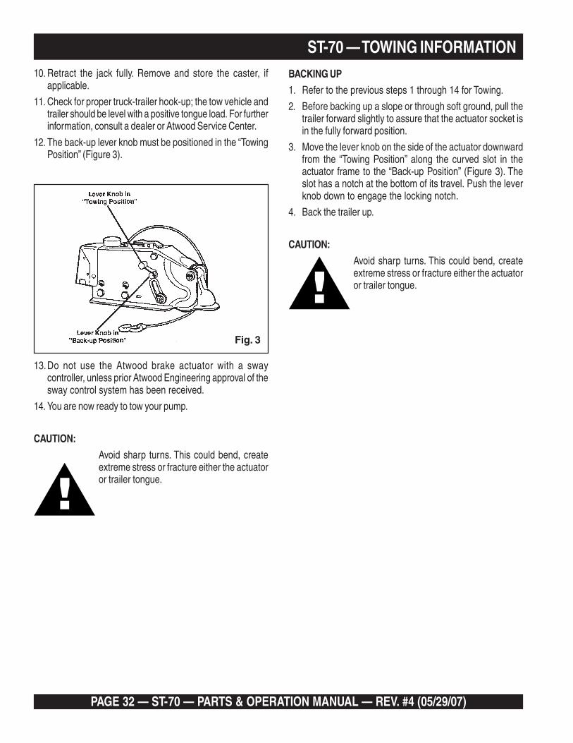
12. The back-up lever knob must be positioned in the “TowingPosition” (Figure 3).
13.Do not use the Atwood brake actuator with a swaycontroller, unless prior Atwood Engineering approval of thesway control system has been received.
14. You are now ready to tow your pump.
CAUTION:
Avoid sharp turns. This could bend, createextreme stress or fracture either the actuatoror trailer tongue.
BACKING UP
1. Refer to the previous steps 1 through 14 for Towing.
2. Before backing up a slope or through soft ground, pull thetrailer forward slightly to assure that the actuator socket isin the fully forward position.
3. Move the lever knob on the side of the actuator downwardfrom the “Towing Position” along the curved slot in theactuator frame to the “Back-up Position” (Figure 3). Theslot has a notch at the bottom of its travel. Push the leverknob down to engage the locking notch.
4. Back the trailer up.
CAUTION:
Avoid sharp turns. This could bend, createextreme stress or fracture either the actuatoror trailer tongue.
ST-70 — TOWING INFORMATION
Fig. 3
ST-70 — PARTS & OPERATION MANUAL — REV. #4 (05/29/07) — PAGE 33
5. If the pump is to be uncoupled from the tow vehicle afterbacking with the lever knob engaged, block all pump wheelsand pull forward slightly to take strain off of the actuator.Uncouple the actuator by lifting the release handle andraising the trailer tongue. Make sure the lever knob is in the“Towing Position” when uncoupling from the trailer.
CAUTION:
Before towing the pump, always ensure thatthe lever knob has disengaged and is in the“Towing Position.”
MAINTENANCE
1. Keep all links and pivots lubricated to prevent rusting andensure ease of operation. Using SAE 30 oil, lubricate insidethe release handle and inside the actuator body. This canbe reached from the underside of the actuator.
NOTE:
Lubricate the hitch ball with conventional automotivegrease or a lubricant made for hitch balls.
2. Check for any leaks in the brake system. Periodic checksshould be made on all hoses to guard against cuts andworn hoses which may cause failure (leaks, rupturingunder pressure, and collapsing). Replace defective hoses.
3. Check the brake fluid level in the master cylinder reservoir.Keep it filled to within ½" from the top of the reservoir.
CAUTION:
Do not fill the master cylinder reservoir withused brake fluid. Do not fill the reservoirbeyond ½" from top. Do not overfill, brake fluidwill damage paint.
4. At the beginning of each year, inspect the brakes forexcessive wear, replace the linings if necessary.
NOTE:
Wheel bearings and seals should be inspected and packedat this time.
Extended Storage Instructions
The following preventative maintenance is recommended forextended periods of storage.
1. Check brake system for proper fluid level in master cylinderand bleed all lines.
2. Lubricate all links and pivots to prevent any rusting.
3. Remove wheel and drum assemblies and spray a goodanti-corrosion compound (CRC formula 5-56) under rubberboot on forward end of brake wheel cylinder. Avoid sprayingdrum and brake lining.
4. Grease all bearings and reinstall wheel and drumassemblies.
5. Make sure breakaway cable is fully released.
6. After extended storage, refer to the Maintenance Stepslisted above to insure that the trailer is ready for towing.
ST-70 — TOWING INFORMATION
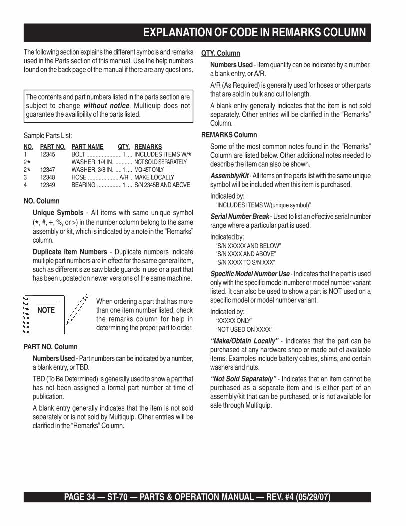
PAGE 34 — ST-70 — PARTS & OPERATION MANUAL — REV. #4 (05/29/07)
EXPLANATION OF CODE IN REMARKS COLUMN
The contents and part numbers listed in the parts section aresubject to change without notice. Multiquip does notguarantee the availibility of the parts listed.
NOTEWhen ordering a part that has morethan one item number listed, checkthe remarks column for help indetermining the proper part to order.
QTY. Column
Numbers Used - Item quantity can be indicated by a number,a blank entry, or A/R.
A/R (As Required) is generally used for hoses or other partsthat are sold in bulk and cut to length.
A blank entry generally indicates that the item is not soldseparately. Other entries will be clarified in the “Remarks”Column.
REMARKS Column
Some of the most common notes found in the “Remarks”Column are listed below. Other additional notes needed todescribe the item can also be shown.
Assembly/Kit - All items on the parts list with the same uniquesymbol will be included when this item is purchased.
Indicated by:“INCLUDES ITEMS W/(unique symbol)”
Serial Number Break - Used to list an effective serial numberrange where a particular part is used.
Indicated by:“S/N XXXXX AND BELOW”“S/N XXXX AND ABOVE”“S/N XXXX TO S/N XXX”
Specific Model Number Use - Indicates that the part is usedonly with the specific model number or model number variantlisted. It can also be used to show a part is NOT used on aspecific model or model number variant.
Indicated by:“XXXXX ONLY”“NOT USED ON XXXX”
“Make/Obtain Locally” - Indicates that the part can bepurchased at any hardware shop or made out of availableitems. Examples include battery cables, shims, and certainwashers and nuts.
“Not Sold Separately” - Indicates that an item cannot bepurchased as a separate item and is either part of anassembly/kit that can be purchased, or is not available forsale through Multiquip.
The following section explains the different symbols and remarksused in the Parts section of this manual. Use the help numbersfound on the back page of the manual if there are any questions.
NO. Column
Unique Symbols - All items with same unique symbol(*, #, +, %, or >) in the number column belong to the sameassembly or kit, which is indicated by a note in the “Remarks”column.
Duplicate Item Numbers - Duplicate numbers indicatemultiple part numbers are in effect for the same general item,such as different size saw blade guards in use or a part thathas been updated on newer versions of the same machine.
PART NO. Column
Numbers Used - Part numbers can be indicated by a number,a blank entry, or TBD.
TBD (To Be Determined) is generally used to show a part thathas not been assigned a formal part number at time ofpublication.
A blank entry generally indicates that the item is not soldseparately or is not sold by Multiquip. Other entries will beclarified in the “Remarks” Column.
Sample Parts List:NO. PART NO. PART NAME QTY. REMARKS1 12345 BOLT ....................... 1 .... INCLUDES ITEMS W/*2* WASHER, 1/4 IN. ........... NOT SOLD SEPARATELY2* 12347 WASHER, 3/8 IN. .... 1 .... MQ-45T ONLY3 12348 HOSE .................... A/R .. MAKE LOCALLY4 12349 BEARING ................ 1 .... S/N 2345B AND ABOVE
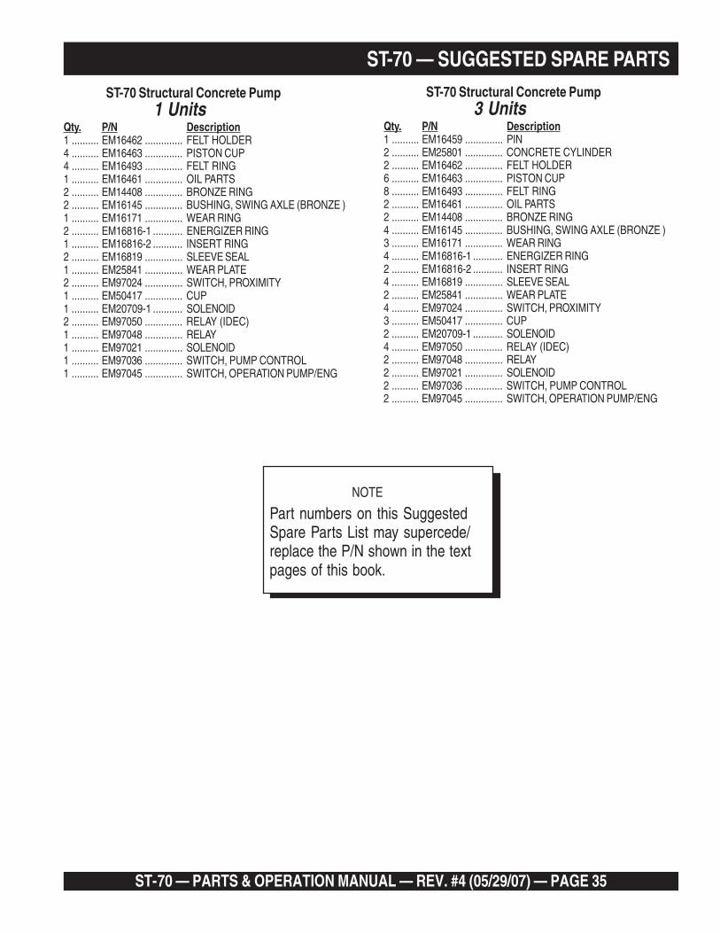
ST-70 — PARTS & OPERATION MANUAL — REV. #4 (05/29/07) — PAGE 35
ST-70 — SUGGESTED SPARE PARTSST-70 Structural Concrete Pump
1 UnitsQty. P/N Description1 .......... EM16462 .............. FELT HOLDER4 .......... EM16463 .............. PISTON CUP4 .......... EM16493 .............. FELT RING1 .......... EM16461 .............. OIL PARTS2 .......... EM14408 .............. BRONZE RING2 .......... EM16145 .............. BUSHING, SWING AXLE (BRONZE )1 .......... EM16171 .............. WEAR RING2 .......... EM16816-1 ........... ENERGIZER RING1 .......... EM16816-2 ........... INSERT RING2 .......... EM16819 .............. SLEEVE SEAL1 .......... EM25841 .............. WEAR PLATE2 .......... EM97024 .............. SWITCH, PROXIMITY1 .......... EM50417 .............. CUP1 .......... EM20709-1 ........... SOLENOID2 .......... EM97050 .............. RELAY (IDEC)1 .......... EM97048 .............. RELAY1 .......... EM97021 .............. SOLENOID1 .......... EM97036 .............. SWITCH, PUMP CONTROL1 .......... EM97045 .............. SWITCH, OPERATION PUMP/ENG
ST-70 Structural Concrete Pump3 Units
Qty. P/N Description1 .......... EM16459 .............. PIN2 .......... EM25801 .............. CONCRETE CYLINDER2 .......... EM16462 .............. FELT HOLDER6 .......... EM16463 .............. PISTON CUP8 .......... EM16493 .............. FELT RING2 .......... EM16461 .............. OIL PARTS2 .......... EM14408 .............. BRONZE RING4 .......... EM16145 .............. BUSHING, SWING AXLE (BRONZE )3 .......... EM16171 .............. WEAR RING4 .......... EM16816-1 ........... ENERGIZER RING2 .......... EM16816-2 ........... INSERT RING4 .......... EM16819 .............. SLEEVE SEAL2 .......... EM25841 .............. WEAR PLATE4 .......... EM97024 .............. SWITCH, PROXIMITY3 .......... EM50417 .............. CUP2 .......... EM20709-1 ........... SOLENOID4 .......... EM97050 .............. RELAY (IDEC)2 .......... EM97048 .............. RELAY2 .......... EM97021 .............. SOLENOID2 .......... EM97036 .............. SWITCH, PUMP CONTROL2 .......... EM97045 .............. SWITCH, OPERATION PUMP/ENG
NOTE
Part numbers on this SuggestedSpare Parts List may supercede/replace the P/N shown in the textpages of this book.

PAGE 36 — ST-70 — PARTS & OPERATION MANUAL — REV. #4 (05/29/07)
The safety instruction decals shown must be on allMayco ST70 — Concrete Pump
ST-70 — DECALS
CAUTION !1 . B e f o r e s e t u p a n d o p e r a t i o n o f t h i s
equipment, the designated operator MUSTr e a d a n d c o m p l e t e l y u n d e r s t a n d t h eo p e r a t i n g i n s t r u c t i o n m a n u a l .
2. keep unauthorized and untrained peopleaway from the machine during operation.
4. Do not place hands in lubrication box atany time.
pressure reading.
5. Keep hands out of hopper when engine isrunning. Do not remove or stand onhopper grates.
6. Check hopper for obstructions beforeoperating machine.
7. This machine is remotely controlled andmay start at any time.
8. Stop engine before adding fuel or oil.
9 . W h e n t h e p u m p , m a n i f o l d o r d e l i v e r ys y s t e m p l u g s , d o N O T d i s c o n n e c t t h ed e l i v e r y s y s t e m c l a m p s o r o p e n t h emanifold. A plug has occurred when thep u m p i s r u n n i n g b u t n o c o n c r e t e i sdischarging from the end of the deliverysystem; immediate ly swi tch the engineO F F . C o n s u l t y o u r o p e r a t i n g a n di n s t r u c t i o n m a n u a l b e f o r e p r o c e e d i n g .
Great care must be taken to clear a pluga s a d a n g e r o u s c o n d i t i o n , d u e t ohigh pressure build-up, inside the pump
and delivery system.
3 . R o t a t i n g o r m o v i n g p a r t s w i l l c a u s es e r i o u s i n j u r y. B e f o r e s e r v i c i n g o rcleaning, turn off the engine and checkaccumulator pressure gauge for ZERO
3
CAUTION TOWING
1. USE ONLY 2" STEEL BALL
3. ALWAYS USE SAFETY CHAIN ANDBREAKAWAY CHAIN WHEN TOWING UNIT.
4. INSPECT ACTUATOR AND BRAKES BEFORETOWING UNIT (REFER TO ATWOOD MANUALDECALS ON HITCH).
2. TOWING VEHICLE AND HITCH MUST BERATED TO TOW 4300 LB. LOAD
2
ATTENTIONA MANUAL MUST BE STOREDIN THIS TUBE AT ALL TIMES.
BEFORE SET-UP AND OPERATION OF THIS EQUIPMENT THEDESIGNATED OPERATOR MUST READ AND COMPLETELY UNDERSTANDTHE OPERATING AND INSTRUCTION MANUAL INSIDE THIS TUBE.
1
4
CAUTION
REFER TO MANUAL FORSERVICE INSTRUCTIONS
CHARGE ONLY WITHDRY NITROGEN
5
6
CAUTION
MINIMUMOIL LEVEL
Oil level below minimumcan cause hydraulic pumpand system damage.Oil temperature shouldnot exceed 170 F (77 C).
7

ST-70 — PARTS & OPERATION MANUAL — REV. #4 (05/29/07) — PAGE 37
ST-70 — DECALSST- 70DECALS
NO. PART NO. PART NAME QTY. REMARKS1 EM935 DECAL, ATTENTION, MANUAL STORAGE 12 EM969 DECAL, CAUTION TOWING 13 EM7072 DECAL, CAUTION OPERATING INSTRUCTIONS 34 EM97084 DECAL, MAINTENANCE 15 EM955 DECAL, CAUTION DRY NITROGEN 16 EM97083 DECAL, WARNING 17 EM97071 DECAL, CAUTION MINIMUM OIL LEVEL 1
EM1028 DECAL, MAYCO LOGO 2EM97082 DECAL, ST-70 2EM97080 DECAL, EMERGENCY CYCLING 1EM965 DECAL, VOLUME CONTROL 1EM995 DECAL, DIESEL FUEL 1EM985 DECAL, HYDRAULIC OIL 1EM97070 DECAL, PRESSURE GAUGES 1EM1032 DECAL, 800 MAYCO PHONE 2EM98000 DECAL, CAUTION GREASE 4EMDCLST70 DECAL KIT, ST70 1 INCLS. ALL ITEM ABOVE
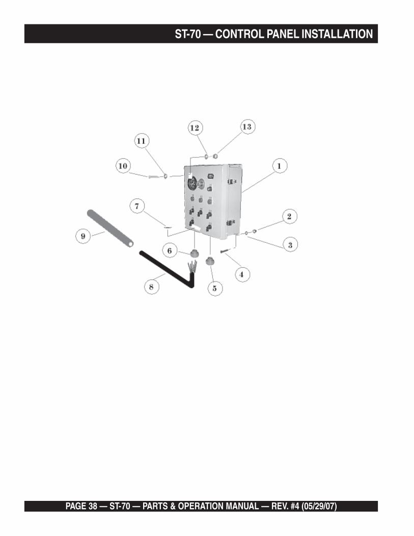
PAGE 38 — ST-70 — PARTS & OPERATION MANUAL — REV. #4 (05/29/07)
ST-70 — CONTROL PANEL INSTALLATION

ST-70 — PARTS & OPERATION MANUAL — REV. #4 (05/29/07) — PAGE 39
ST-70 — CONTROL PANEL INSTALLATIONST- 70CONTROL PANEL INTALLATION
NO. PART NO. PART NAME QTY. REMARKS1 EM97073 PANEL, CONTROL ASSY 12 EM492661 NUT, 1/4"-NC HEX. 23 EM492622 WASHER, 1/4" LOCK 24 EM492357 BOLT, 1/4"-NC x 1" HEX. 25 EM491873 CONNECTOR 16 EM5015901 CONNECTOR 37 EM491876 WASHER, CONNECTOR 48 EM509738 CABLE 18 GA. 19 EM509588 POLIFLEX 110 EM503112 BOLT, 3/8"-NC x 2 3/4" HEX. 211 EM923027 WASHER, 3/8" 212 EM923350 WASHER, LOCK 3/8" 213 EM492554 NUT 3/8"-NC HEX. 2
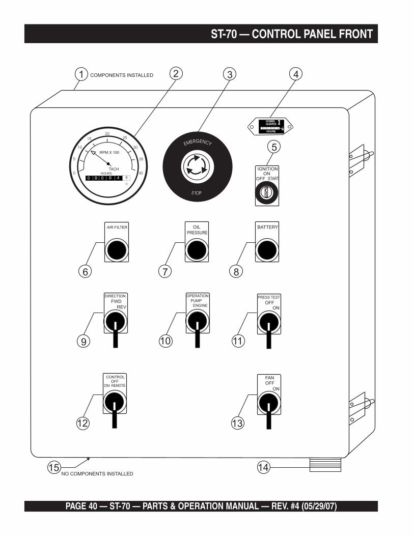
PAGE 40 — ST-70 — PARTS & OPERATION MANUAL — REV. #4 (05/29/07)
ST-70 — CONTROL PANEL FRONT
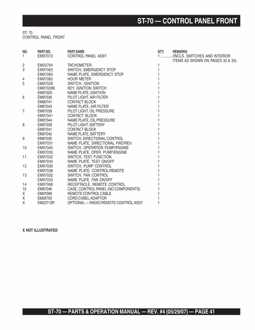
ST-70 — PARTS & OPERATION MANUAL — REV. #4 (05/29/07) — PAGE 41
ST-70 — CONTROL PANEL FRONTST- 70CONTROL PANEL FRONT
NO. PART NO. PART NAME QTY. REMARKS1 EM97073 CONTROL PANEL ASSY 1 ............ (INCLS. SWITCHES AND INTERIOR
ITEMS AS SHOWN ON PAGES 32 & 33).2 EM25704 TACHOMETER 13 EM97063 SWITCH, EMERGENCY STOP 1
EM97064 NAME PLATE, EMERGENCY STOP 14 EM97062 HOUR METER 15 EM97028 SWITCH, IGNITION 1
EM97028K KEY, IGNITION SWITCH 1EM97029 NAME PLATE, IGNITION 1
6 EM97039 PILOT LIGHT, AIR FILTER 1EM90741 CONTACT BLOCK 1EM97043 NAME PLATE, AIR FILTER 1
7 EM97039 PILOT LIGHT, OIL PRESSURE 1EM97041 CONTACT BLOCK 1EM97044 NAME PLATE, OIL PRESSURE 1
8 EM97039 PILOT LIGHT, BATTERY 1EM97041 CONTACT BLOCK 1EM97042 NAME PLATE, BATTERY 1
9 EM97030 SWITCH, DIRECTIONAL CONTROL 1EM97031 NAME PLATE, DIRECTIONAL FWD/REV. 1
10 EM97045 SWITCH, OPERATION PUMP/ENGINE 1EM97035 NAME PLATE, OPER. PUMP/ENGINE 1
11 EM97032 SWITCH, TEST FUNCTION 1EM97034 NAME PLATE, TEST ON/OFF 1
12 EM97036 SWITCH, PUMP CONTROL 1EM97038 NAME PLATE, CONTROL/REMOTE 1
13 EM97032 SWITCH, FAN CONTROL 1EM97033 NAME PLATE, FAN ON/OFF 1
14 EM97068 RECEPTACLE, REMOTE CONTROL 115 EM97046 CASE, CONTROL PANEL (NO COMPONENTS) 1X EM97099 REMOTE CONTROL CABLE 1X EM26793 CORD CABEL ADAPTOR 1X EM23713R OPTIONAL — RADIO REMOTE CONTROL ASSY 1
X NOT ILLUSTRATED

PAGE 42 — ST-70 — PARTS & OPERATION MANUAL — REV. #4 (05/29/07)
ST-70 — CONTROL PANEL INTERIOR
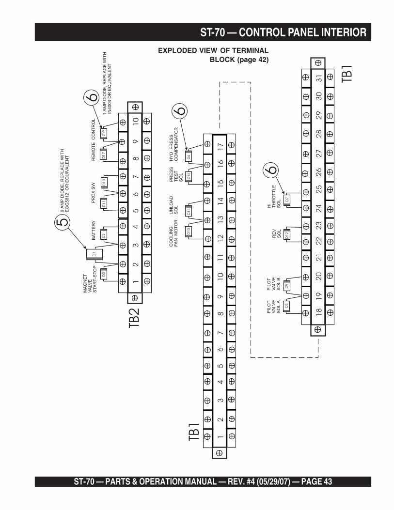
ST-70 — PARTS & OPERATION MANUAL — REV. #4 (05/29/07) — PAGE 43
ST-70 — CONTROL PANEL INTERIOR
TB1
TB2
TB1
12
29
6
6
23
5
5
22
13
30
7
7
241
4
31
8
8
25
1
1
18
15
9
9
26
2
2
19
16
10
10
27
3
3
51
6
6
6
20
17
11
28
4
4
21
D1
3
D1
1D
3D
2
D1
D1
2D
7D
8
D1
5
D1
7
D1
4
D1
0
D9
D6
D1
9
CO
OLIN
GFA
NM
OT
OR
PR
OX
SW
MA
GN
ET
VA
LV
ES
TA
RT
-ST
OP
BA
TT
ER
Y
RE
VS
OL
HI
TH
RO
TT
LE
SO
L
PIL
OT
VA
LV
ES
OL
A
PIL
OT
VA
LV
ES
OL
B
UN
LO
AD
SO
LP
RE
SS
TE
ST
SO
L
HY
DP
RE
SS
CO
MP
EN
SA
TO
R
RE
MO
TE
CO
NT
RO
L
1A
MP
DIO
DE
,R
EP
LA
CE
WIT
HIN
4004
OR
EQ
UIV
ALE
NT
6A
MP
DIO
DE
,R
EP
LA
CE
WIT
HE
GG
5812
OR
EQ
UIV
ALE
NT
K3
K5
D1
6D
20
41
49
EXPLODED VIEW OF TERMINALBLOCK (page 42)
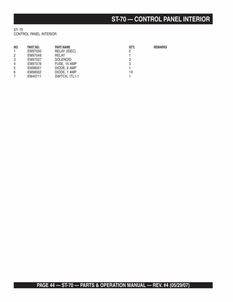
PAGE 44 — ST-70 — PARTS & OPERATION MANUAL — REV. #4 (05/29/07)
ST-70 — CONTROL PANEL INTERIORST- 70CONTROL PANEL INTERIOR
NO. PART NO. PART NAME QTY. REMARKS1 EM97050 RELAY (IDEC) 22 EM97048 RELAY 13 EM97027 SOLENOID 34 EM97078 FUSE, 15 AMP 35 EM98001 DIODE, 6 AMP 16 EM98002 DIODE, 1 AMP 197 EM40711 SWITCH, ITL1-1 1
ST-70 — PARTS & OPERATION MANUAL — REV. #4 (05/29/07) — PAGE 45
NOTE PAGE

PAGE 46 — ST-70 — PARTS & OPERATION MANUAL — REV. #4 (05/29/07)
ST-70 — MAIN DRIVE PUMPS
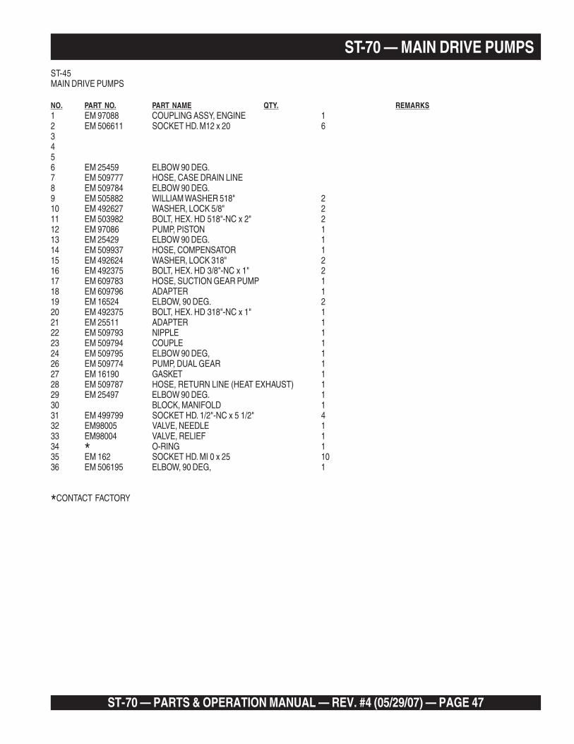
ST-70 — PARTS & OPERATION MANUAL — REV. #4 (05/29/07) — PAGE 47
ST-70 — MAIN DRIVE PUMPSST-45MAIN DRIVE PUMPS
NO. PART NO. PART NAME QTY. REMARKS1 EM 97088 COUPLING ASSY, ENGINE 12 EM 506611 SOCKET HD. M12 x 20 63456 EM 25459 ELBOW 90 DEG.7 EM 509777 HOSE, CASE DRAIN LINE8 EM 509784 ELBOW 90 DEG.9 EM 505882 WILLIAM WASHER 518" 210 EM 492627 WASHER, LOCK 5/8" 211 EM 503982 BOLT, HEX. HD 518"-NC x 2" 212 EM 97086 PUMP, PISTON 113 EM 25429 ELBOW 90 DEG. 114 EM 509937 HOSE, COMPENSATOR 115 EM 492624 WASHER, LOCK 318" 216 EM 492375 BOLT, HEX. HD 3/8"-NC x 1" 217 EM 609783 HOSE, SUCTION GEAR PUMP 118 EM 609796 ADAPTER 119 EM 16524 ELBOW, 90 DEG. 220 EM 492375 BOLT, HEX. HD 318"-NC x 1" 121 EM 25511 ADAPTER 122 EM 509793 NIPPLE 123 EM 509794 COUPLE 124 EM 509795 ELBOW 90 DEG, 126 EM 509774 PUMP, DUAL GEAR 127 EM 16190 GASKET 128 EM 509787 HOSE, RETURN LINE (HEAT EXHAUST) 129 EM 25497 ELBOW 90 DEG. 130 BLOCK, MANIFOLD 131 EM 499799 SOCKET HD. 1/2"-NC x 5 1/2" 432 EM98005 VALVE, NEEDLE 133 EM98004 VALVE, RELIEF 134 * O-RING 135 EM 162 SOCKET HD. MI 0 x 25 1036 EM 506195 ELBOW, 90 DEG, 1
*CONTACT FACTORY

PAGE 48 — ST-70 — PARTS & OPERATION MANUAL — REV. #4 (05/29/07)
ST-70 — MANIFOLD CONTROL
2A
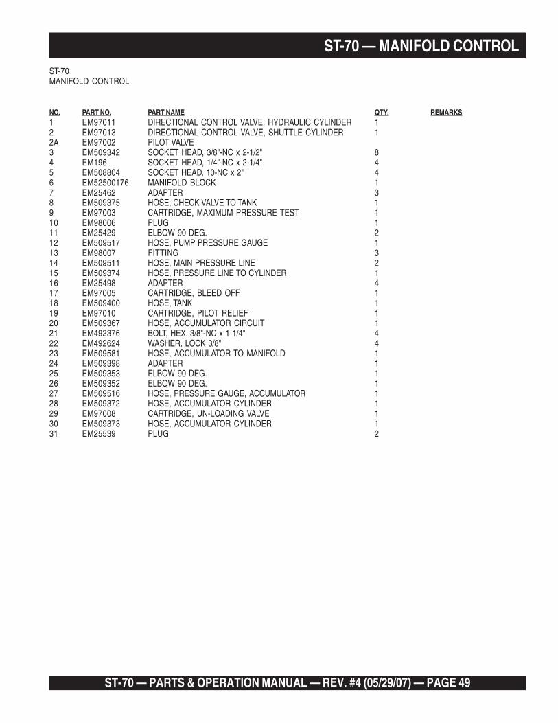
ST-70 — PARTS & OPERATION MANUAL — REV. #4 (05/29/07) — PAGE 49
ST-70MANIFOLD CONTROL
NO. PART NO. PART NAME QTY. REMARKS1 EM97011 DIRECTIONAL CONTROL VALVE, HYDRAULIC CYLINDER 12 EM97013 DIRECTIONAL CONTROL VALVE, SHUTTLE CYLINDER 12A EM97002 PILOT VALVE3 EM509342 SOCKET HEAD, 3/8"-NC x 2-1/2" 84 EM196 SOCKET HEAD, 1/4"-NC x 2-1/4" 45 EM508804 SOCKET HEAD, 10-NC x 2" 46 EM52500176 MANIFOLD BLOCK 17 EM25462 ADAPTER 38 EM509375 HOSE, CHECK VALVE TO TANK 19 EM97003 CARTRIDGE, MAXIMUM PRESSURE TEST 110 EM98006 PLUG 111 EM25429 ELBOW 90 DEG. 212 EM509517 HOSE, PUMP PRESSURE GAUGE 113 EM98007 FITTING 314 EM509511 HOSE, MAIN PRESSURE LINE 215 EM509374 HOSE, PRESSURE LINE TO CYLINDER 116 EM25498 ADAPTER 417 EM97005 CARTRIDGE, BLEED OFF 118 EM509400 HOSE, TANK 119 EM97010 CARTRIDGE, PILOT RELIEF 120 EM509367 HOSE, ACCUMULATOR CIRCUIT 121 EM492376 BOLT, HEX. 3/8"-NC x 1 1/4" 422 EM492624 WASHER, LOCK 3/8" 423 EM509581 HOSE, ACCUMULATOR TO MANIFOLD 124 EM509398 ADAPTER 125 EM509353 ELBOW 90 DEG. 126 EM509352 ELBOW 90 DEG. 127 EM509516 HOSE, PRESSURE GAUGE, ACCUMULATOR 128 EM509372 HOSE, ACCUMULATOR CYLINDER 129 EM97008 CARTRIDGE, UN-LOADING VALVE 130 EM509373 HOSE, ACCUMULATOR CYLINDER 131 EM25539 PLUG 2
ST-70 — MANIFOLD CONTROL
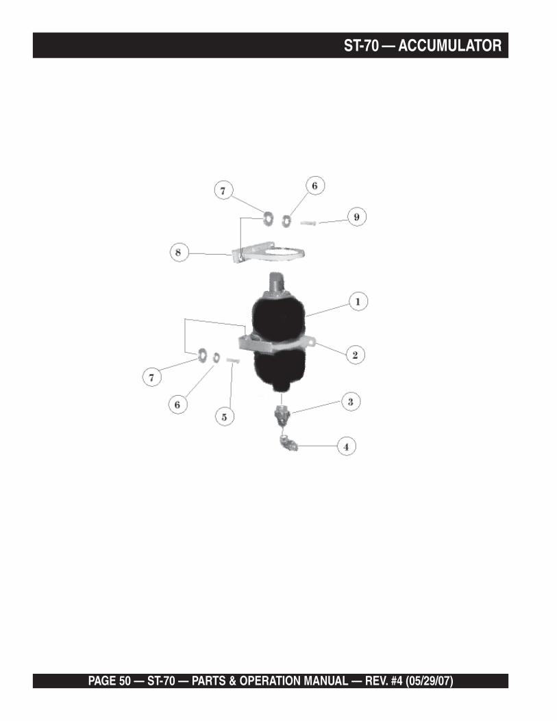
PAGE 50 — ST-70 — PARTS & OPERATION MANUAL — REV. #4 (05/29/07)
ST-70 — ACCUMULATOR

ST-70 — PARTS & OPERATION MANUAL — REV. #4 (05/29/07) — PAGE 51
ST-70 — ACCUMULATORST-70ACCUMULATOR
NO. PART NO. PART NAME QTY. REMARKS1 EM97015 ACCUMULATOR 12 EM97016 CLAMP 13 EM509425 ADAPTER 14 EM509353 ELBOW 90 DEG. 15 EM509562 BOLT, HEX. HD 3/8"-NC x 5/8" 26 EM492624 WASHER, LOCK 3/8"-NC 27 EM492598 WASHER, 3/8" 28 EM509444 BRACKET 19 EM492373 BOLT, HEX. HD 3/8"-NC x 3/4" 2
* EM98099 ACCUMULATOR REPAIR KIT 1
*NOT ILLUSTRATED

PAGE 52 — ST-70 — PARTS & OPERATION MANUAL — REV. #4 (05/29/07)
ST-70 — HYDRAULIC/CONCRETE CYLINDERS

ST-70 — PARTS & OPERATION MANUAL — REV. #4 (05/29/07) — PAGE 53
ST-70 — HYDRAULIC/CONCRETE CYLINDERSST-70HYDRAULIC / CONCRETE CYLINDERS
NO. PART NO. PART NAME QTY. REMARKS1 EM510265 BOLT, HEX. HD. 3/8"-NC x 3 1/4" 62 EM16464 PLATE, FACE 23 EM16465 SPACER 64 EM16463 PISTON CUP 25 EM14408 RING, BRONCE 26 EM16493 RING, FELT 27 EM16462 FELT HOLDER 48 EM16461 PLATE, OILER 29 EM14407 O-RING 210 EM25801 CYLINDER, CONCRETE 211 EM25110 RETAINER, CYLINDER 412 EM492624 WASHER, LOCK 3/8" 1413 EM492598 WASHER, 3/8" 2214 EM492375 BOLT, HEX. HD. 3/8"-NC x 1" 815 EM16174 O-RING 216 EM492451 BOLT, HEX. HD. 3/8"-NF x 1" 817 EM50443 SEAL, OIL 818 EM509417 TANK, LUBE 119 EM492378 BOLT, HEX. HD. 3/8"-NC x 1 3/4" 120 EM508517 COVER, TANK 121 EM50425 FLANGE 222 EM27435-1 SEAL 223 EM16460 ADAPTER 224 EM97076 CYLINDER HYDRAULIC 125 EM97077 CYLINDER HYDRAULIC 126 EM25497 ELBOW 427 EM16454 CLEVIS PIN 228 EM505723 COTTER PIN 5/32" x 1-½” 429 EM97024 SWITCH, PROXIMITY 230 EM97025 CONDUCTOR, CYLINDER SWITCH 231 EM18447 PLUG PIPE 3/4" 132 EM25474 HOSE 133 EM25843 PLATE, WEAR 134 EM265 BOLT, FLAT SOCKET HD. 5/8"-NC 235 EM264 BOLT, FLAT SOCKET HD. 1/2"-NC 136 EM295 BOLT, FLAT SOCKET HD. 3/4"-NC 2

PAGE 54 — ST-70 — PARTS & OPERATION MANUAL — REV. #4 (05/29/07)
ST-70 — SHUTTLE TUBE ASSY
38
39
ST-70 — PARTS & OPERATION MANUAL — REV. #4 (05/29/07) — PAGE 55
ST-70 — SHUTTLE TUBE ASSYST-70SHUTTLE TUBE ASSY
NO. PART NO. PART NAME QTY. REMARKS
1 EM417 NUT, LOCK 1"-14 NS 12 EM509221 NUT, HEX1"-14 NS 13 EM16814 TENSIONER 14 EM25236 AXLE, CRANK 15 EM16169 WASHER, THRUST 16 EM16145 BUSHING, BRONZE 27 EM492397 BOLT, HEX 1/2"-NC x 2-1/2" 48 EM25454 CYLINDER, SHUTTLE 19 EM210 BOLT, HEX. HD 1/2"-NC x 3-1/4" 610 EM25803 BEARING, DISCHARGE NIPPLE 111 EM16819 SEAL 112 EM25836 NIPPLE, DISCHARGE 113 EM25454-9 BASE, CYLINDER 114 EM621 WILLIAM WASHER, 1/2" 415 EM492626 WASHER, LOCK 1/2" 416 EM492584 NUT, LOCK 1/2" 117 EM284 STUD, 1"-14 NS 118 EM16175 O-RING 119 EM16170 RING, SEAL 120 EM16176 O-RING 121 EM25843 NUN PLATE 122 EM16171 RING, WEAR 123 EM16816-2 RING, INSERT 124 EM16816-1 RING, ENERGIZER 125 EM492393 BOLT, HEX. HD 1/2"-NC x 1-1/4" 426 EM16802 PLATE, INSPECTION 127 EM20816 O-RING 128 EM16811 SHUTTLE TUBE 129 EM492627 WASHER, LOCK 5/8" 830 EM503982 BOLT, HEX. HD 5/8"-NC x 2" 831 EM25836 NIPPLE, DISCHARGE 132 EM28906 COUPLING 5", OPTIONAL 133 EM25837 ELBOW, REDUCING, 5" x 4", OPTIONAL 134 EM25568 GREASE FITTING 135 EM16426 GREASE FITTING 136 EM25500 ELBOW 45 DEG. 137 EM25459 ELBOW 90 DEG. 138 EM717 PIN, COTTER 139 EM26126 PIN, CLEVIS 1
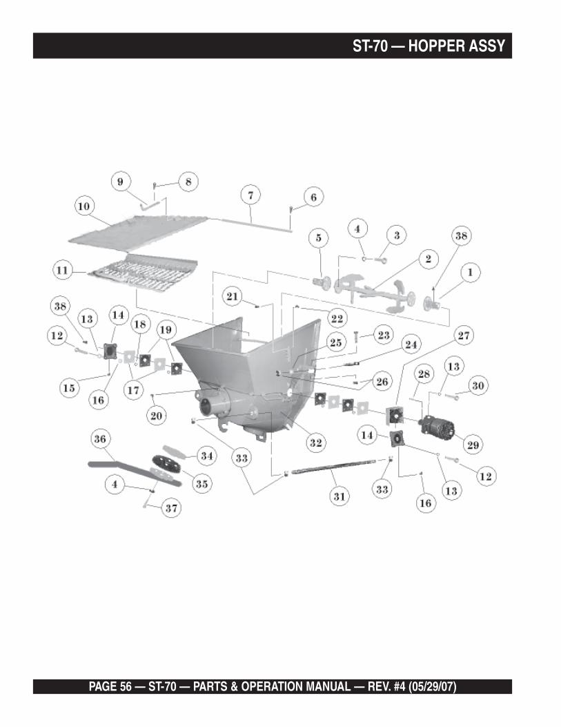
PAGE 56 — ST-70 — PARTS & OPERATION MANUAL — REV. #4 (05/29/07)
ST-70 — HOPPER ASSY
ST-70 — PARTS & OPERATION MANUAL — REV. #4 (05/29/07) — PAGE 57
ST-70 — HOPPER ASSYST-70HOPPER ASSY
NO. PART NO. PART NAME QTY. REMARKS1 EM25301 SHAFT DRIVE END 12 EM25863 REMIXER 13 EM492375 BOLT, HEX HD 3/8"-NC x 1" 84* EM492624 WASHER, LOCK 3/8" 125 EM23305 SHAFT, DRIVE END 16 EM491686 COTTER PIN 1/8" x 1-3/4" 27 EM16159 PIN, HINGE 18 EM505723 COTTER PIN 5/32" x 1-1/2" 19 EM70134-2 PIN, SPLASH 110 EM70134 PLATE, SPLASH 111 EM16188 SCREEN, HOPPER 112 EM492397 BOLT, HEX HD 1/2"-NC x 2-1/2" 813 EM492626 WASHER, LOCK 1/2" 1014 EM18135 BEARING, FLANGE 215 EM25568 FITTING LUBE, 45 DEG. 216 EM22250 SPACER 417 EM18136 PLATE, SPACER 818 EM18138 SPACER, SEAL 1619 EM18137 SEAL, SHAFT 420 EM16426 FITTING, LUBE, 90 DEG. 321 EM508812 FITTING, LUBE 522 EM491701 FITTING, GREASE 523 EM505121 BOLT, HEX HD 3/4"-NC x3" 424 EM14165 EYE BOLT 425 EM619 WILLIAM WASHER 3/4" 426 EM492558 NUT 3/4"-NC 827 EM50141 BRACKET, MOTOR MTG. 128 EM505719 KEY 129 EM25425 MOTOR, REMIXER 130 EM492394 BOLT, HEX HD 1/2"-NC x 1-1/2" 231 EM16166 TIE ROD 232 EM25174 HOPPER 133 EM505728 NUT, HEX. 1"-NC 6
EM70860 HOPPER CLEAN OUT PLUG, ASSY ........................ 1 ........................ INCLS. ITEMS W/*34* EM70860-1 PLATE, TOP 135* EM50417 CUP 136* EM508830 HANDLE 137* EM492378 BOLT, HEX HD 3/8"-NC x 1-3/4" 438 EM491698 FITTING, GREASE 2
* 16184 HOPPER SEAL 1
*NOT ILLUSTRATED

PAGE 58 — ST-70 — PARTS & OPERATION MANUAL — REV. #4 (05/29/07)
ST-70 — REMIXER CONTROL ASSY

ST-70 — PARTS & OPERATION MANUAL — REV. #4 (05/29/07) — PAGE 59
ST-70 — REMIXER CONTROL ASSYST-70REMIXER CONTROL ASSY
NO. PART NO. PART NAME QTY. REMARKS1 EM25425 MOTOR, REMIXER 12 EM25508 ELBOW, 45 DEG. 23 EM25483 HOSE, MOTOR TO VALVE 24 EM25509 ADAPTER 25 EM509378 HOSE, RETURN TO HEAT EXCHANGER 16 EM25507 ELBOW, 90 DEG. 17 EM25495 VALVE, REMIXER 18 EM492553 NUT, HEX. 5/16"-NC 29 EM492623 WASHER, LOCK 5/16" 210 EM218 BOLT, HEX. HD 5/16"-NC x 2 1/2" 211 EM509370 HOSE, TO BEAR PUMP 112 EM98014 TEST PORT 113 EM98015 ADAPTOR 114 EM25563 TEE 1
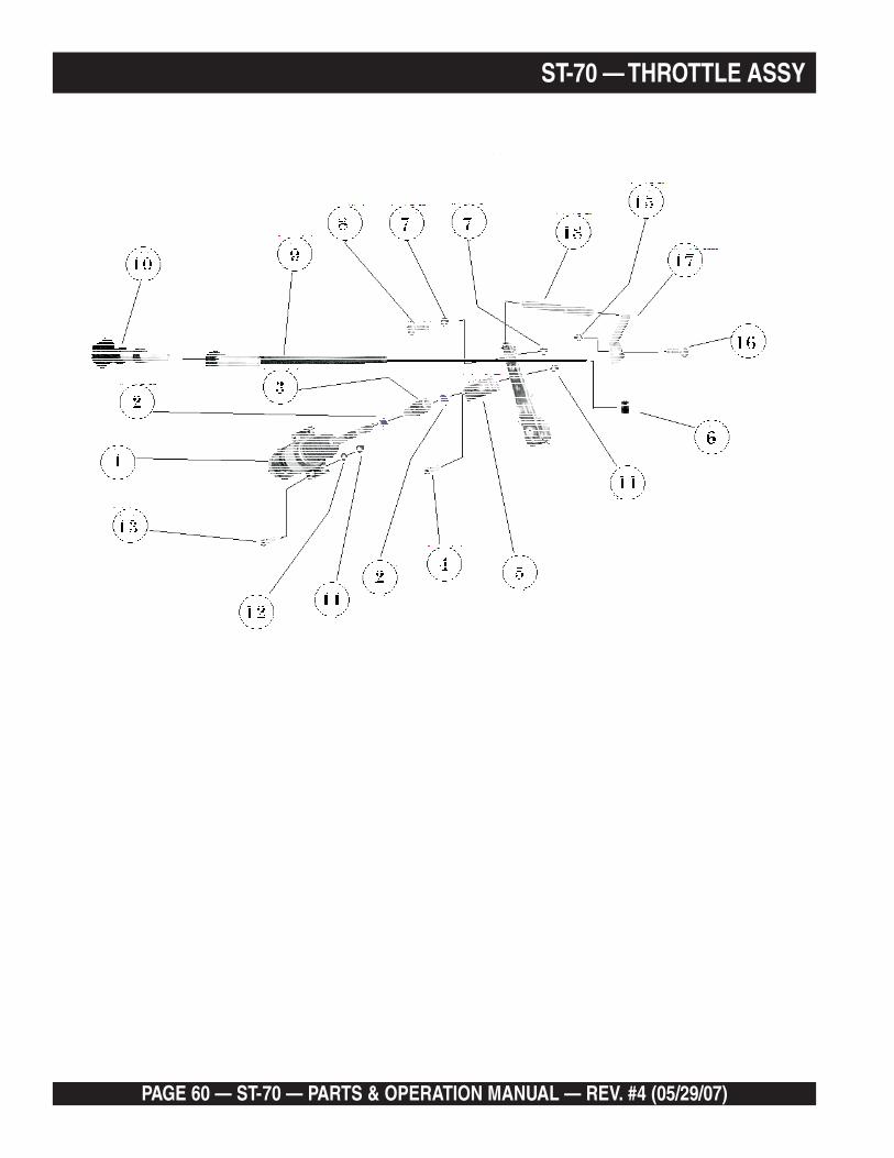
PAGE 60 — ST-70 — PARTS & OPERATION MANUAL — REV. #4 (05/29/07)
ST-70 — THROTTLE ASSY
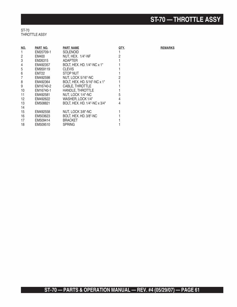
ST-70 — PARTS & OPERATION MANUAL — REV. #4 (05/29/07) — PAGE 61
ST-70 — THROTTLE ASSYST-70THROTTLE ASSY
NO. PART NO. PART NAME QTY. REMARKS1 EM20709-1 SOLENOID 12 EM400 NUT, HEX. 1/4"-NF 23 EM26315 ADAPTER 14 EM492357 BOLT, HEX. HD. 1/4"-NC x 1" 15 EM959119 CLEVIS 16 EM722 STOP NUT 17 EM492598 NUT, LOCK 5/16"-NC 28 EM492364 BOLT, HEX. HD. 5/16"-NC x 1" 19 EM16740-2 CABLE, THROTTLE 110 EM16740-1 HANDLE, THROTTLE 111 EM492581 NUT, LOCK 1/4"-NC 512 EM492622 WASHER, LOCK 1/4" 413 EM508821 BOLT, HEX. HD. 1/4"-NC x 3/4" 41415 EM492558 NUT, LOCK 3/8"-NC 116 EM503623 BOLT, HEX. HD. 3/8"-NC 117 EM509414 BRACKET 118 EM509510 SPRING 1
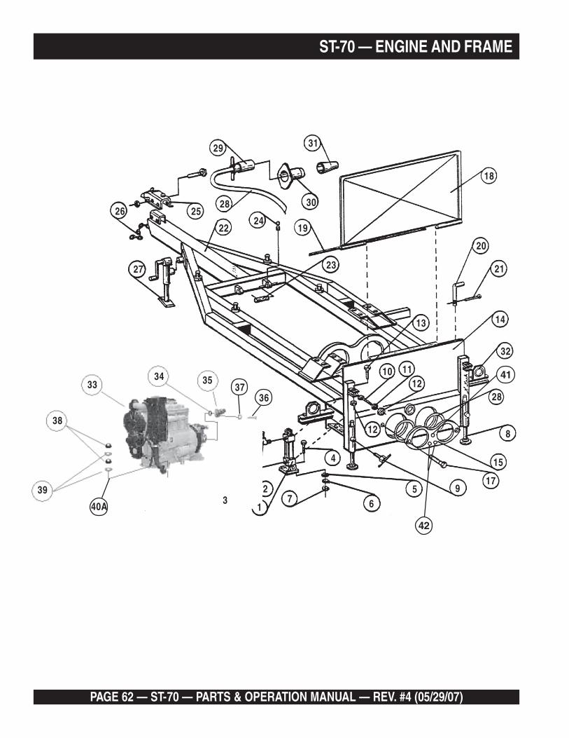
PAGE 62 — ST-70 — PARTS & OPERATION MANUAL — REV. #4 (05/29/07)
ST-70 — ENGINE AND FRAME
3433 35
3637
28
29
2422
25
19
30
23
31
26
27
10
28
32
14
21
12
1211
13
8
4
917
15
57 6
2
13
18
20
39
38
40A
41
42

ST-70 — PARTS & OPERATION MANUAL — REV. #4 (05/29/07) — PAGE 63
ST-70 — ENGINE AND FRAMEST-70ENGINE AND FRAME
NO. PART NO. PART NAME QTY. REMARKS1 EM25454 CYLINDER, SHUTTLE 12 EM25459 ELBOW, 3/4" x 90° 13 EM25500 ELBOW, 3/4" x 45° 14 EM132 BOLT, HEX HD, 1/2-13 x 2" 45 EM621 WILLIAM WASHER, 1/2" 46 EM606 WASHER, LOCK, 1/2" 47 EM404 NUT, HEX, 1/2"-13 48 EM25160 STAND, REAR STABLIZER 29 EM14138 HANDLE, TEE 210 EM14165 BOLT, EYE 411 EM619 WILLIAM WASHER, 3/4" 412 EM407 NUT, HEX, 3/4-10 813 EM119 BOLT, HEX, 3/4-10 x 3" 414 EM26112 PLATE ASSY, REAR 115 EM25841 PLATE, WEAR 116 EM16174 O-RING, WAER PLATE 217 EM295 BOLT, HEX HD 218 EM70134 PLATE, SPLASH 119 EM16159 PIN, HINGE, SPLASH PLATE 120 EM70134-2 PIN, SPLASH PLATE 121 EM717 PIN, COTTER 122 EM80101 FRAME ASSY 123 EM16459 PIN, CLEVIS 224 EM14169 GREASE FITTING 225 EM16602 2" HYDRAULIC SURGE BRAKE ASSY 126 EM25610 JACK STAND, SWIVEL 127 EM20135 CHAIN, SAFETY 128 EM25608 WIRE, #16/5 x 18' 129 EM25607-1 PLUG, MALE #16/5 130 EM25607-2 SOCKET, FEMALE #16/5 131 EM25607-3 BOOT 132 EM26536 LIGHT, TAIL 233 EM25711 ENGINE, DIESEL HATZ 4M40L 134 EM509436 O-RING 135 EM527442 ELBOW 45° 136 EM492394 BOLT, HEX HD, 1/2"-NC x 1-1/2" 437 EM635 WASHER, LOCK 1/2" 438 020310080 NUT 239 030210250 WASHER 240 EM01060100 SHOCK ABSORBER 440A EM03642900 STUD, SHOCK ABSORBER 841 EM264 BOLT 1/2" x 13 x 3" 142 EM265 BOLT 5/8" x 11 x 3" 2
* 510269 ENGINE HOOD 1
*NOT ILLUSTRATED

PAGE 64 — ST-70 — PARTS & OPERATION MANUAL — REV. #4 (05/29/07)
ST-70 — OIL COOLER ASSY

ST-70 — PARTS & OPERATION MANUAL — REV. #4 (05/29/07) — PAGE 65
ST-70 — OIL COOLER ASSYST-70OIL COOLER ASSY
NO. PART NO. PART NAME QTY. REMARKS1 EM509805 GUARD, COOLER 12 EM492364 BOLT, HEX. HD. 5/16"-NC x 1" 43 EM923023 WASHER, 5/16" 44 EM509791 COOLER 15 EM509779 HOSE 16 EM509802 SHROUD, COOLER 17 EM492622 WASHER, LOCK 1/4" 48 EM492356 BOLT, HEX. HD. 1/4"-NC x 3/4" 49 EM492376 BOLT, HEX. HD. 3/8"-NC x 1" 210 EM492598 WASHER, 3/8" 211 EM492583 NUT, LOCK 3/8"-NC 212 EM509402 NUT 113 EM509345 FITTING 114 EM509344 TEE 115 EM509401 ELBOW, 90 DEG. 116 EM509343 TEE 1
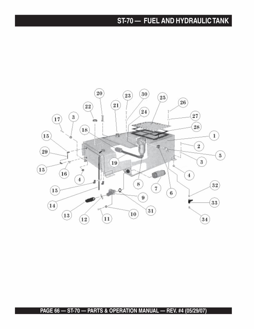
PAGE 66 — ST-70 — PARTS & OPERATION MANUAL — REV. #4 (05/29/07)
ST-70 — FUEL AND HYDRAULIC TANK

ST-70 — PARTS & OPERATION MANUAL — REV. #4 (05/29/07) — PAGE 67
ST-70 — FUEL AND HYDRAULIC TANKST-70FUEL AND HYDRAULIC TANK
NO. PART NO. PART NAME QTY. REMARKS1 EM509406 TANK, FUEL & HYDRAULIC 12 EM175 BOLT, HEX 3/8"-NC x 1 1/4" 43 EM492598 WASHER 3/8" 54 EM492583 NUT, LOCK 3/8" 55 EM18436 ELBOW 16 EM16517 REDUCER 17 EM50424 STRAINER 18 EM16433 ELBOW 19 EM27441 ELBOW 110 EM635 WASHER, HI-COLLAR 1/2" 411 EM492455 BOLT, HEX 1/2"-NF x 1-1/2" 412 EM26471 CLAMP 113 EM509437 HOSE 114 EM508826 TUBE, PLASTIC 115 EM20426 ELBOW 416 EM20421 VALVE 117 EM503117 BOLT, HEX 3/8"-NC x 3" 118 EM16513 DEFUSER 119 EM16516 PIPE 120 EM16478 GAUGE, LEVEL-TEMP. 121 EM16477 FILL CAP ASSY. 122 EM25217 CAP, GAS 123 EM492375 BOLT, HEX 3/8"-NC x 1" 424 EM16512 FILTER 125 EM25119-1 COVER 126 EM492374 BOLT, HEX 5/16"-NC x 1" 2027 EM492623 WASHER, LOCK 5/16" 2028 EM25184 GASKET 129 EM508827 TUBE, PLASTIC 130 EM492624 WASHER 3/8" 131 EM50466 O-RING 132 EM509369 ADAPTER 133 EM491237 VALVE 134 EM506094 PLUG 1
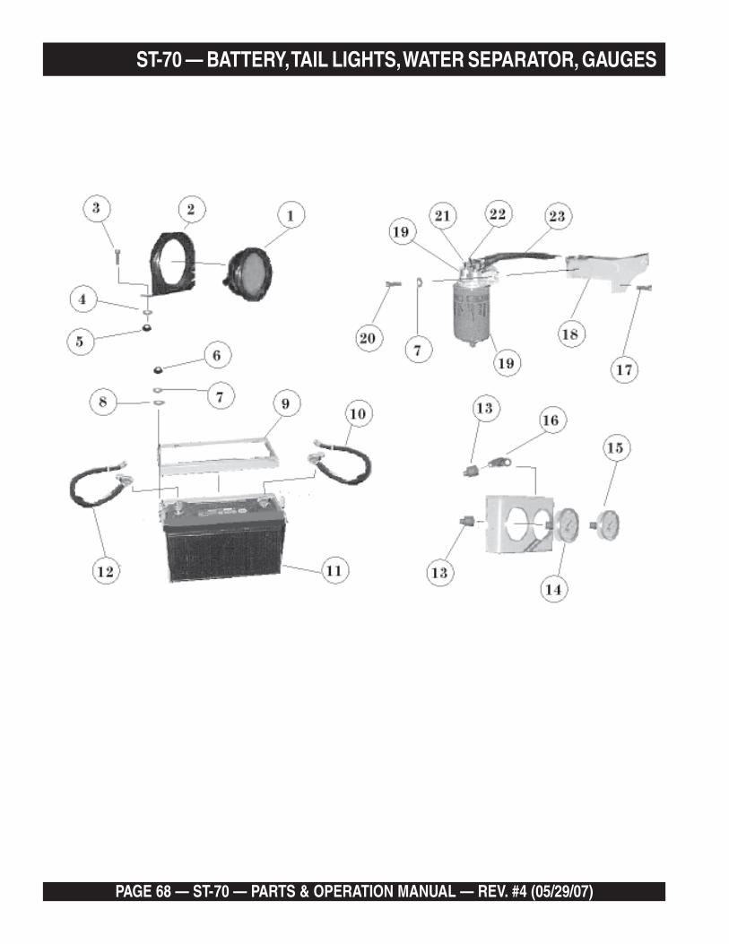
PAGE 68 — ST-70 — PARTS & OPERATION MANUAL — REV. #4 (05/29/07)
ST-70 — BATTERY, TAIL LIGHTS, WATER SEPARATOR, GAUGES

ST-70 — PARTS & OPERATION MANUAL — REV. #4 (05/29/07) — PAGE 69
ST-70 — BATTERY, TAIL LIGHTS, WATER SEPARATOR, GAUGESST-70BATTERY, TAIL LIGHTS, WATER SEPARATOR, GAUGES
NO. PART NO. PART NAME QTY. REMARKS1 EM26536 LIGHT, TAIL 22 EM26536-1 BRACKET, TAIL LIGHT 23 EM492364 BOLT, HEX. 5/16"-NC x 1" 44 EM492623 WASHER, LOCK 5/16" 45 EM492553 NUT, HEX. 5/16"-NC 46 EM492561 NUT, HEX.1/4"-NC 27 EM492622 WASHER, LOCK 1/4" 58 EM492596 WASHER 1/4" 29 EM25708 FRAME 110 EM509105 CABLE, BATTERY GROUND 111 EM16738 BATTERY, 12 VOLT 112 EM16707 CABLE, BATTERY POSITIVE 113 EM25523 ADAPTER 214 EM97066 GAUGE, ACCUMULATOR PRESSURE 115 EM97067 GAUGE, MAIN 116 EM491396 ELBOW 117 EM269 SOCKET HEAD, M10 x 30 218 EM509449 BRACKET, WATER SEPERATOR FILTER 119 EM16747 FILTER ASSY., WATER SEPERATOR 119A EM26465 ELEMENT, FILTER 120 EM492356 BOLT, HEX. HD 1/4"-NC x 3/4" 321 EM20426 ELBOW, 90 DEG. 222 EM716 CLAMP, HOSE 223 EM20427 HOSE 1

PAGE 70 — ST-70 — PARTS & OPERATION MANUAL — REV. #4 (05/29/07)
ST-70 — AXLE AND BRAKES
78 9
1023
11
26
2225
2422
21
6
12
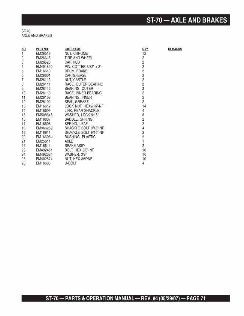
ST-70 — PARTS & OPERATION MANUAL — REV. #4 (05/29/07) — PAGE 71
ST-70 — AXLE AND BRAKESST-70AXLE AND BRAKES
NO. PART NO. PART NAME QTY. REMARKS1 EM26519 NUT, CHROME 122 EM26615 TIRE AND WHEEL 23 EM26520 CAP, HUB 24 EM491690 PIN, COTTER 5/32" x 2" 25 EM16610 DRUM, BRAKE 26 EM26601 CAP, GREASE 27 EM26113 NUT, CASTLE 28 EM26111 RACE, OUTER BEARING 29 EM26112 BEARING, OUTER 210 EM26110 RACE, INNER BEARING 211 EM26108 BEARING, INNER 212 EM26109 SEAL, GREASE 213 EM16612 LOCK NUT, HEX9/16"-NF 1414 EM16609 LINK, REAR SHACKLE 415 EM508846 WASHER, LOCK 9/16" 816 EM16607 SADDLE, SPRING 217 EM16608 SPRING, LEAF 218 EM966259 SHACKLE BOLT 9/16"-NF 419 EM16611 SHACKLE BOLT 9/16"-NF 220 EM16608-1 BUSHING, PLASTIC 221 EM25611 AXLE 122 EM16614 BRAKE ASSY 223 EM492451 BOLT, HEX 3/8"-NF 1024 EM492624 WASHER, 3/8" 1025 EM492574 NUT, HEX 3/8"/NF 1026 EM16605 U-BOLT 4
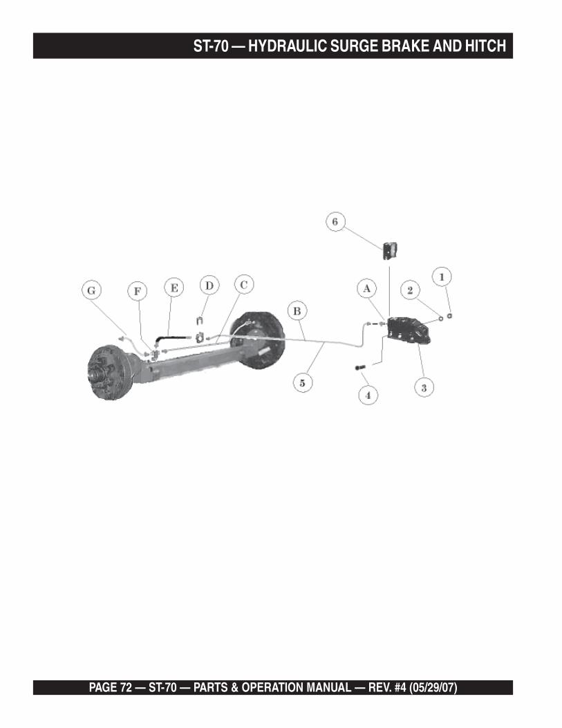
PAGE 72 — ST-70 — PARTS & OPERATION MANUAL — REV. #4 (05/29/07)
ST-70 — HYDRAULIC SURGE BRAKE AND HITCH

ST-70 — PARTS & OPERATION MANUAL — REV. #4 (05/29/07) — PAGE 73
ST-70 — HYDRAULIC SURGE BRAKE AND HITCHST-70HYDRAULIC SURGE BRAKE AND HITCH
NO. PART NO. PART NAME QTY. REMARKS1 EM492584 NUT 1/2"-NC HEX. 22 EM492626 WASHER, LOCK 1/2" 23 EM16602 2" HYDRAULIC SURGE BRAKE ASSY 1 .................FOR COMPONENTS: CONTACT YOUR
LOCAL ATWOOD DEALER.4 EM492401 BOLT, HEX. 1/2"-NC x 4" 25 EM16116 KIT, BRAKE 1 ................. INCLS. ( A, B, C, D, E, F, G) FOR THESE
COMPONENTS. CONTACT YOUR MAYCOPARTS DEPT.
6 EM16602-1 COVER 1

PAGE 74 — ST-70 — PARTS & OPERATION MANUAL — REV. #4 (05/29/07)
SERSERSERSERSERVICEVICEVICEVICEVICE INFORMA INFORMA INFORMA INFORMA INFORMATIONTIONTIONTIONTION

ST-70 — PARTS & OPERATION MANUAL — REV. #4 (05/29/07) — PAGE 75
ST-70 — INTERIOR CONTROL PANEL (Inside Door)
-3-3
-3
-4-4
-2
-2
-2
-4 -4
-2
-4 -2
-1
-1
-1
-3 -3
-1
-3 -1
-4
86
4 B
A
43
34
?
44
17 4
50 55 57
573748
2
22 47
45
46
32
33
31
32
46
5332
46
46
4 30
WH
ITE
WH
ITE
SW-1
PB-1
A2A1
SW-2 SW-3
SW-5
SW-4
SW-6
TO TB1 AND TB2
PL1PL3 PL2
NOTE: ADDITIONAL ILLUSTRATIONSPAGE 42, 43
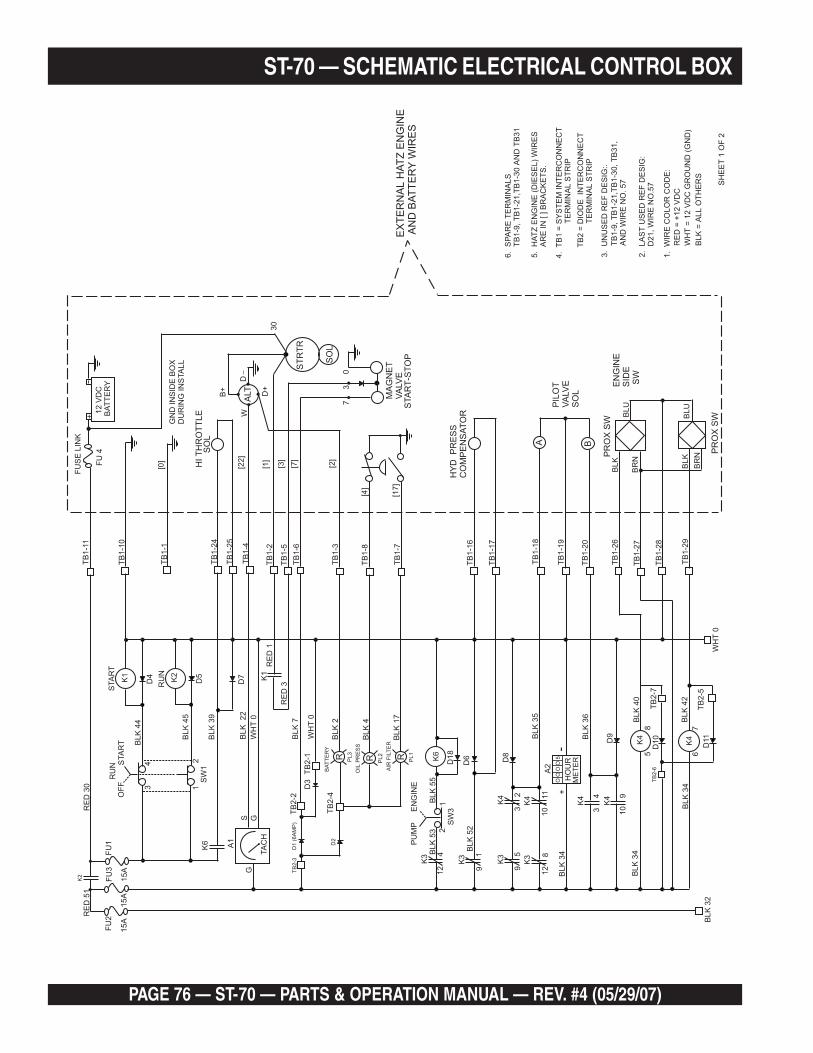
PAGE 76 — ST-70 — PARTS & OPERATION MANUAL — REV. #4 (05/29/07)
SW
1
BLK
44
FU
SE
LIN
K
GN
DIN
SID
EB
OX
DU
RIN
GIN
STA
LL
FU
4B
AT
TE
RY
+
BLK
53
BLK
52
BLK
35
BLK
34
BLK
34
BLK
36
BLK
40
BLK
34
BLK
32
BLK
42
WH
T0
BLK
BLK
BLU
BLU
BR
N
BR
N
TB
2-7
TB
2-5
TB
2-6
BLK
55
SW
3
BLK
45
BLK
39
WH
T0
RE
D1
RE
D3
BLK
7
BLK
17
BLK
4
BLK
2
WH
T0
TB
2-2
TB
2-4
PL3
PL2
PL1
TB
2-1
BA
TT
ER
Y
AIR
FIL
TE
R
OIL
PR
ES
S
BLK
22
S G
D1
(6A
MP
)
D2
D6 D8
D9
D10
D11
D18
D3
R R R
G
12
VD
C
TB
1-1
0
TB
1-1
TB
1-1
1
TB
1-2
4
TB
1-1
6
6.
SP
AR
ET
ER
MIN
ALS
1.
WIR
EC
OLO
RC
OD
E:
BLK
=A
LL
OT
HE
RS
SH
EE
T1
OF
2
WH
T=
12
VD
CG
RO
UN
D(G
ND
)
RE
D=
+12
VD
C
2.
LA
ST
US
ED
RE
FD
ES
IG:
D21,W
IRE
NO
.57
3.
UN
US
ED
RE
FD
ES
IG:.
4.
TB
1=
SY
ST
EM
INT
ER
CO
NN
EC
TT
ER
MIN
AL
ST
RIP
TB
2=
DIO
DE
INT
ER
CO
NN
EC
TT
ER
MIN
AL
ST
RIP
5.
HA
TZ
EN
GIN
E(D
IES
EL)
WIR
ES
AR
EIN
[]B
RA
CK
ET
S.
TB
1-9
,T
B1-2
1,T
B1-3
0A
ND
TB
31
TB
1-9
,T
B1-2
1,T
B1-3
0,T
B31,
AN
DW
IRE
NO
.57
TB
1-1
8
TB
1-1
9
TB
1-2
0
TB
1-2
6
TB
1-2
7
TB
1-2
8
TB
1-2
9
[22]
[0]
[1]
[3]
[7]
[2]
[4]
[17]
73
0
30
ALT
SO
L
MA
GN
ET
VA
LV
ES
TA
RT
-ST
OP
EX
TE
RN
AL
HA
TZ
EN
GIN
EA
ND
BA
TT
ER
YW
IRE
S
HY
DP
RE
SS
CO
MP
EN
SA
TO
R
PIL
OT
VA
LV
ES
OL
EN
GIN
ES
IDE
SW
PR
OX
SW
PR
OX
SW
A B
ST
RT
R
W
D+
D
B+
TB
1-2
5
TB
1-1
7
TB
1-4
TB
1-2
TB
1-5
TB
1-6
TB
1-3
TB
1-8
TB
1-7
SO
LH
IT
HR
OT
TLE
TB
2-3
D4
D5
D7
STA
RT
RU
N
K1
K4
K4
K2
K1
K6
EN
GIN
E
STA
RT
PU
MP
OF
FR
UN
FU
1F
U2
K2
K6
K3
K3
K4
K4
K4
K4
K3
K3
A1
A2
OO
OO
5
TA
CH
ME
TE
RH
OU
R
RE
D30
RE
D51
15A
15A
15A
FU
3
2
1 8
9
12
12 9
3 3 10
5 6
8 7
10
4 5
+-
2 4 911
134
1
2
ST-70 — SCHEMATIC ELECTRICAL CONTROL BOX
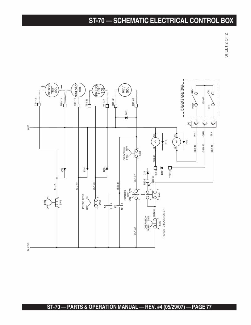
ST-70 — PARTS & OPERATION MANUAL — REV. #4 (05/29/07) — PAGE 77
ST-70 — SCHEMATIC ELECTRICAL CONTROL BOX
SW
5
SW
4
SW
2
SW
6
BL
K5
0
SW
3
J1
K5
K5
FA
N
WH
T
DIR
EC
TIO
N
PR
ES
ST
ES
T
CO
NT
RO
L
OP
ER
AT
ION
(RE
FE
RT
OL
OC
AT
ION
B7
)
BL
K3
1
BL
K3
2
BL
K3
2
BL
K3
2
BL
K3
3
BL
K3
8 BLK
37
BLK
41
BL
K5
7
BLK
49
WH
TF
WD
0F
F
RE
V
ON
RE
MO
TE
CO
NT
RO
L
PU
MP
GR
N
BL
K
GR
N56
BLK
48
TB
2-8
TB
2-9
TB
2-1
0
TB
1-2
2
TB
1-1
6
TB
1-1
5
TB
1-1
3
TB
1-1
4
TB
1-1
2
TB
1-2
3
D13
D12
RE
V
PR
ES
S
MO
TO
R
UN
LO
AD
SO
L
TE
ST
SO
L
TE
ST
SO
L
SO
L
D14
D15
D16
D20
K3
K5
13
13
14
14
D19
D17
ON
RE
V
ON
RE
M
EN
G
OF
F
FW
D
OF
F
ON
PU
MP
OF
F
3
3
4
2
2
3 3
5 8
9 12
4
4
3
1
1
4 4
+
SH
EE
T2
OF
2
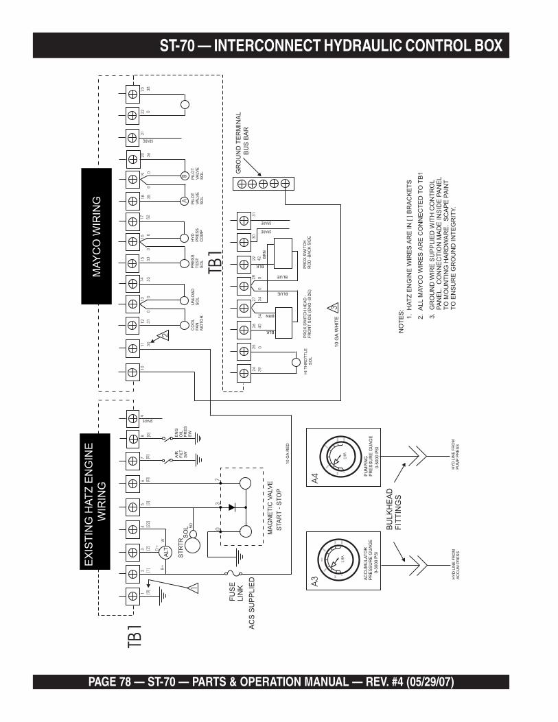
PAGE 78 — ST-70 — PARTS & OPERATION MANUAL — REV. #4 (05/29/07)
ALT
ST
RT
R
FU
SE
LIN
K
AC
SS
UP
PLIE
D
SO
L
14
71
21
51
82
2
24
26
28
29
30
31
21
81
31
61
92
3
25
27
91
41
72
0
SPARE
10
GA
RE
D
SPARE
SPARE
SPARE
UN
LO
AD
SO
LC
OO
LFA
NM
OT
OR
PR
ES
ST
ES
TS
OL
PR
OX
SW
ITC
HH
EA
D-
FR
ON
TS
IDE
(EN
G-S
IDE
)P
RO
XS
WIT
CH
RO
D-B
AC
KS
IDE
BLK
BLK
BRN
BR
N
BLUE
BLUE
PIL
OT
VA
LV
ES
OL
PIL
OT
VA
LV
ES
OL
HY
DP
RE
SS
CO
MP
HIT
HR
OT
TLE
SO
L
10
GA
WH
ITE
61
15
10
23
B+
50
W
AIR
FIL
TS
W
NO
TE
S:
1.
HA
TZ
EN
GIN
EW
IRE
SA
RE
IN[]B
RA
CK
ET
S
GR
OU
ND
TE
RM
INA
L
BU
SB
AR
2.
ALL
MA
YC
OW
IRE
SA
RE
CO
NN
EC
TE
DT
OT
B1
3.
GR
OU
ND
WIR
ES
UP
PLIE
DW
ITH
CO
NT
RO
LP
AN
EL.
CO
NN
EC
TIO
NM
AD
EIN
SID
EP
AN
EL
TO
MO
UN
TIN
GH
AR
DW
AR
E.
SC
AP
EP
AIN
TT
OE
NS
UR
EG
RO
UN
DIN
TE
GR
ITY.
EN
GO
ILP
RE
SS
W
D+
[0]
[22
][0
]3
13
33
5
AB
33
52
36
[0]
00
00
39
40
34
34
42
00
03
8
00
0
03
7
MA
GN
ET
ICV
ALV
E
AC
CU
MU
LA
TO
RP
RE
SS
UR
EG
UA
GE
HY
DL
INE
FR
OM
AC
CU
MP
RE
SS
HY
DL
INE
FR
OM
PU
MP
PR
ES
S
BU
LK
HE
AD
FIT
TIN
GS
PU
MP
ING
PR
ES
SU
RE
GU
AG
E
0-5
000
PS
I0-3
000
PS
I
STA
RT
-S
TO
P
[0]
30
[3]
[1]
[2]
TB1
TB1
EX
IST
ING
HA
TZ
EN
GIN
EM
AY
CO
WIR
ING
WIR
ING
3000
2000
50
00
30
00
15
00
LHA
A4
A3
LHA
0
0
40
00
25
00
10
00
50
0
2000
1000
2
3
1
ST-70 — INTERCONNECT HYDRAULIC CONTROL BOX
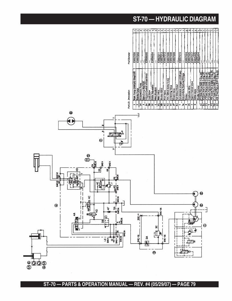
ST-70 — PARTS & OPERATION MANUAL — REV. #4 (05/29/07) — PAGE 79
ST-70 — HYDRAULIC DIAGRAM
EM
9702
6
— — EM
9800
5— E
M98
004
— EM
9701
1E
M97
013
EM
9700
6E
M97
012
EM
9702
4—E
M97
015
—EM
9700
8E
M97
009
————EM
2545
4E
M25
425
— — —EM
9700
2
EM
9702
5E
M97
017
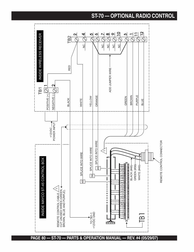
PAGE 80 — ST-70 — PARTS & OPERATION MANUAL — REV. #4 (05/29/07)
ST-70 — OPTIONAL RADIO CONTROL
ST-70 — PARTS & OPERATION MANUAL — REV. #4 (05/29/07) — PAGE 81
The service procedures contained in this manual are intendedfor use by an individual equipped with the proper tools andequipment and familiar with safe shop practices.
Should questions arise during the service or repair . . . stop . . .and contact Mayco service department. 1-800-30-MAYCO.
Do not open hydraulic lines or loosen hydraulicfittings while engine is running! Hydraulic fluidunder pressure can penetrate the skin, blind,cause burns or create other potentiallydangerous hazards follow all safetyinstructions as described throughout thismanual.
Warning! Danger of Amputation!
The Mayco pump is equipped with a nitrogenaccumulator, which stores hydraulic energy.You will be required to put your hand in theconcrete cylinders or near the suttle. You areat extreme risk if the engine is running or ifpressure is in the hydraulic system. Prior to
working on the pump, stop the engine by turning off the ignitionswitch, remove starter key, place a “Do not operate” tag over theswitch and disconnect the battery. The pressure reading on theaccumulator pressure gauge must read zero. Always relievethe accumulator circuit to zero pressure prior to working on thepump.
Use only original Mayco components. Thequality of the components is critical to theoperator’s safety and performance of themachine.
ST-70 — SERVICE INFORMATION

PAGE 82 — ST-70 — PARTS & OPERATION MANUAL — REV. #4 (05/29/07)
ST-70 — SERVICE INFORMATIONMaintenance check schedule
yaD ruoH keeW htnoM htnom-6 ruoH/emiT
lioenignE x x
retlifriaenignE x
retlifleuF x 005
levelliociluardyH x
xobnoitacirbuL x
liociluardyHecalpeR 0012
sretlifciluardyhnaelC x
knarcelxA x
ebut”S“skrezesaerG x 2
gniraebximeresaerG x
erusserpmetsyskcehC x 04
ssenthgitroferawdraH x 04
gnirerawgnittuC x
noitcnufekarbreliarT x
thgilekarB x
noitidnoceriT x
slaced,secivedytefaS x
sgniraebleehW x
yrettaB x
gninilekarB x
tcepsniyllausiv,skaelliO x
1. When changing the hydraulic oil or topping off the reservoir,use only the following type. (Reservoir capacity 58 gal.)
Hydraulic oil: Shell Oil Tellius 68 or
Mobil DFE 26
Texaco Rand HDC
The Mayco pump is equipped with an in-tank return hydraulicfilter with a 10 micron cleanable filter. The element has beendesigned to remove all particles large enough to cause wearand job break down. Under normal conditions, we recommendreplacement every 6 month.
Do not mix oil brands! This may impair quality.
The most important factor to keep in mind is the effect of coldweather on the hydraulic oil. The viscosity (thickness) of thehydraulic oil will be much heavier.
Always run machine until oil temperature reaches a minimumof 50 degrees F. before pumping. Damage to the main pistonpump will occur if the machine is cycled too fast before the oiltemperature reaches the minimum of 50 degrees. Cycle themachine at 6-8 strokes per minute at approximately 1/3 throttle.In – areas where the weather normally remains under 50degrees F., use Shell Oil Tellus – 46, or the equivalent. Theabove steps must be followed or severe damage to the mainaxial piston pump will be the end result.
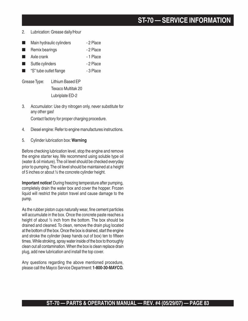
ST-70 — PARTS & OPERATION MANUAL — REV. #4 (05/29/07) — PAGE 83
2. Lubrication: Grease daily/Hour
■ Main hydraulic cylinders - 2 Place
■ Remix bearings - 2 Place
■ Axle crank - 1 Place
■ Suttle cylinders - 2 Place
■ “S” tube outlet flange - 3 Place
Grease Type: Lithium Based EP
Texaco Multitak 20
Lubriplate ED-2
3. Accumulator: Use dry nitrogen only, never substitute forany other gas!
Contact factory for proper charging procedure.
4. Diesel engine: Refer to engine manufactures instructions.
5. Cylinder lubrication box: Warning
Before checking lubrication level, stop the engine and removethe engine starter key. We recommend using soluble type oil(water & oil mixture). The oil level should be checked everydayprior to pumping. The oil level should be maintained at a heightof 5 inches or about ½ the concrete cylinder height.
Important notice! During freezing temperature after pumping,completely drain the water box and cover the hopper. Frozenliquid will restrict the piston travel and cause damage to thepump.
As the rubber piston cups naturally wear, fine cement particleswill accumulate in the box. Once the concrete paste reaches aheight of about ½ inch from the bottom. The box should bedrained and cleaned. To clean, remove the drain plug locatedat the bottom of the box. Once the box is drained, start the engineand stroke the cylinder (keep hands out of box) ten to fifteentimes. While stroking, spray water inside of the box to thoroughlyclean out all contamination. When the box is clean replace drainplug, add new lubrication and install the top cover.
Any questions regarding the above mentioned procedure,please call the Mayco Service Department: 1-800-30-MAYCO.
ST-70 — SERVICE INFORMATION

PAGE 84 — ST-70 — PARTS & OPERATION MANUAL — REV. #4 (05/29/07)
ST-70 — SERVICE INFORMATIONST70 Pressure Setting Sequence
(Setting maximum pump pressure)
Step 1: Remove acorn nut from pressure compensator (locatedon the top front of the Rexroth pump. The compensatoris the lower of the two valves) loosen the jam nut andturn the allen screw clockwise until it seats.
Step 2: Loosen the jam nut located on the end of thecompensator valve.
Step 3: Turn the compensator adjustment nut (large) clockwiseuntil tight.
Step 4: Start the engine, loosen the jam nut located on themaximum relief valve cartridge, small manifold port3C. Run engine at maximum Rpm (2350), turn volumecontrol knob counter clockwise to maximum volumeposition. Locate the electrical control panel, turn thepump switch to the on position, next turn the test switchon. Using an allen wrench adjust the main relief (port3C) valve to 3500 PSI. The reading can be taken frompump pressure gauge. Hold the allen adjusting boltwith wrench and tighten jam nut. Using the test switchdouble check the pressure reading to make sure thesetting has not changed.
Step 5: Cycle the pump at maximum Rpm’s (2350) at fullvolume. Turn maximum pressure test switch on. Withan allen wrench adjust compensator allen bolt counterclockwise until (3300) PSI is reached. Lock jam nutand turn maximum pressure test switch off. Let pumpcycle 10 or 20 times and turn pressure test switch on tomake sure the pump is at maximum pressure. Lock thejam nut.

ST-70 — PARTS & OPERATION MANUAL — REV. #4 (05/29/07) — PAGE 85
ST-70 — SERVICE INFORMATION
ST-70 Accumulator Circuit
The accumulator circuit has two functions in the hydraulicsystem.
1. The accumulator circuit furnishes the hydraulic pressureto cycle the shuttle tube.
2. The accumulator circuit also furnishes the pilot pressurenecessary to activate the hydraulic system.
The accumulator circuit is equipped with a bladder typeaccumulator charged with 1100 PSI of dry nitrogen. Theaccumulator stores one gallon of hydraulic oil, which is, under1750 PSI of pressure. When the pump cycles, a part of thestored oil is released to the shuttle cylinder, this pressure releaseassures the shuttle tube has enough force to shear the cylinderof concrete passing from the concrete cylinder to the concretedelivery line during the cycle phase.
Setting pressures in the accumulator circuit
Attach 3000 PSI test gage to port 2-G of the main control block.
(Pressure test gauge Mayco P/N 98016)
The unloading valve cartridge, located in port 4-E, loosen locknut and with an allen wrench turn adjusting screw clockwiseuntil it is completely closed.
Turn the pump switch and run engine at 2350 Rpm’s and adjustthe accumulator circuit pilot relief valve cartridge, located atport 4-G. Loosen lock nut, turn allen adjusting screw untilpressure gauge reads 1950 PSI, and tighten lock nut. Turn engineoff and on several times to make the pressure continues to read1950 PSI. With relief valve set at 1950 PSI it is time to adjust theunloading cartridge. Turn on pump and run at 2350 Rpm’s andmaximum volume. Using the accumulator pressure gaugelocated by control panel, adjust unloading valve cartridgecounter clockwise until the pressure reaches 1750 PSI. Startand stop pump several times to make sure accumulator circuitpressure is holding at 1750 PSI. At this time tighten lock nut onunloading valve cartridge. Your accumulator circuit pressureshould now be properly adjusted.
Checking accumulator bladder pressure
The accumulator charge pressure should read 1100 PSI. Tocheck pressure, start engine and stroke the pump. Theaccumulator pressure gauge should read 1750 PSI. Todetermine the actual accumulator PSI, stop engine and observethe pressure gauge. As the PSI reading slowly decreases it willreach a point where there will be a sudden drop in the PSI. ThePSI reading should be taken prior to this sudden drop. If you donot read 1100 PSI the accumulator may require charging orbladder replacement.
Warning – Explosion caused by improper accumulatorcharging can result in serious injury or death! Never use oxygenor compressed air to charge the accumulator! Only qualifiedpersonal should perform this procedure. Use only dry nitrogento charge the accumulator. Contact your Mayco servicedepartment or your local Hydac representative for propercharging procedure.
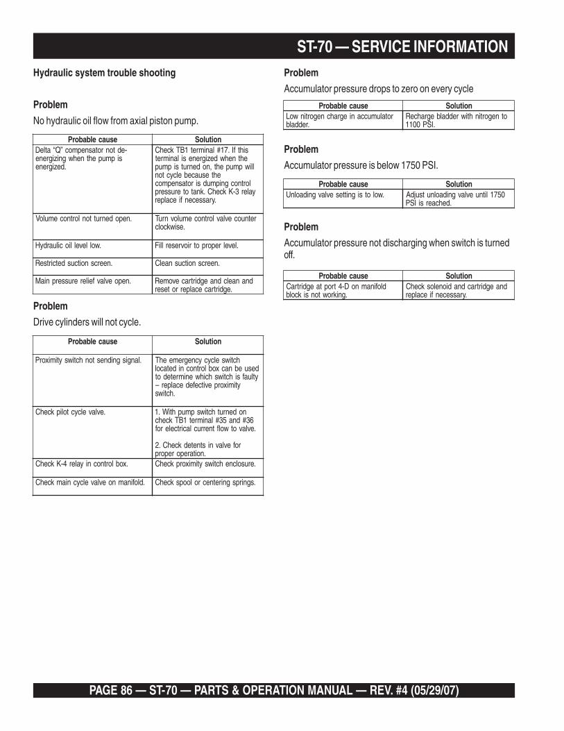
PAGE 86 — ST-70 — PARTS & OPERATION MANUAL — REV. #4 (05/29/07)
ST-70 — SERVICE INFORMATIONHydraulic system trouble shooting
Problem
No hydraulic oil flow from axial piston pump.
Problem
Drive cylinders will not cycle.
Problem
Accumulator pressure drops to zero on every cycle
esuacelbaborP noituloS-edtonrotasnepmoc”Q“atleD
sipmupehtnehwgnizigrene.dezigrene
sihtfI.71#lanimret1BTkcehCehtnehwdezigrenesilanimret
lliwpmupeht,nodenrutsipmupehtesuacebelcycton
lortnocgnipmudsirotasnepmocyaler3-KkcehC.knatoterusserp
.yrassecenfiecalper
.nepodenruttonlortnocemuloV retnuocevlavlortnocemulovnruT.esiwkcolc
.wollevelliociluardyH .levelreporpotriovreserlliF
.neercsnoitcusdetcirtseR .neercsnoitcusnaelC
.nepoevlavfeilererusserpniaM dnanaelcdnaegdirtracevomeR.egdirtracecalperroteser
esuacelbaborP noituloS
.langisgnidnestonhctiwsytimixorP hctiwselcycycnegremeehTdesuebnacxoblortnocnidetacolytluafsihctiwshcihwenimretedot
ytimixorpevitcefedecalper–.hctiws
.evlavelcyctolipkcehC nodenruthctiwspmuphtiW.163#dna53#lanimret1BTkcehc
.evlavotwolftnerruclacirtcelerof
rofevlavnistnetedkcehC.2.noitareporeporp
.xoblortnocniyaler4-KkcehC .erusolcnehctiwsytimixorpkcehC
.dlofinamnoevlavelcycniamkcehC .sgnirpsgniretnecroloopskcehC
Problem
Accumulator pressure is below 1750 PSI.
esuacelbaborP noituloSrotalumuccaniegrahcnegortinwoL
.reddalbotnegortinhtiwreddalbegrahceR
.ISP0011
Problem
Accumulator pressure not discharging when switch is turnedoff.
esuacelbaborP noituloS.wolotsignittesevlavgnidaolnU 0571litnuevlavgnidaolnutsujdA
.dehcaersiISP
esuacelbaborP noituloSdlofinamnoD-4troptaegdirtraC
.gnikrowtonsikcolbdnaegdirtracdnadioneloskcehC
.yrassecenfiecalper

ST-70 — PARTS & OPERATION MANUAL — REV. #4 (05/29/07) — PAGE 87
ST-70 — SERVICE INFORMATIONElectrical System
Proximity switches
The proximity is a normally open switch. The proximity developsa radio frequency, which is emitted from the face of the proximityswitch. As the hydraulic drive cylinder piston passes throughthe radio frequency, the circuit closes and a signal is sent to thepilot cycle valve. This valve cycles the pump and causes theconcrete to flow.
This proximity switch is designed to work at hydraulic pressuresof 5000 PSI and oil temperatures of 250o Fahrenheit.
Problem
At the completion of a pumping stroke the pumping pressuregauge indicates high pressure and the pump doesn’t cycle.
If the emergency cycle switch doesn’t cycle the pump it maywell be a problem with the K-4 relay. A quick check for a problemwith the K-4 relay is to use a hot jumper wire. Connect (jumperwire) to terminals #35 and #36 on terminal block #1. Whencontact is made between these two terminals and the pumpcycles. This would indicate that you have a faulty K-4 relay.
esuacelbaborP noituloSagnittimetonsihctiwsytimixorP
.ycneuqerfoidaranisimetsysciluardyhehtfI
llup,noitidnocerusserpmumixamelcycycnegremeehtnoelggoteht
edisnidetacol(drawothctiwspmupehtfiuoy)xoblortnoc
hctiwsytimixorpehtecalperselcycpmupehtfI.xobnoitacirbulehtta
elggotehthsupuoynehwselcyclortnocehtforoiretniehtdrawot
hctiwsytimixorpehtecalperxob.pmupehtfodnegniwotehtno
Electrical
Problem
When starter switch is activated and nothing occurs.
Problem
Hatz engine will not continue to run after key is released.
esuacelbaborP noituloS.sesufytluaF ,lenaplortnocnikcolbesufkcehC
esufkcehC.sesufnwolbecalper,dionelosenignewolebdetacolknil
.yrettabottxen
esuacelbaborP noituloS.deliafsahedoidID ecalperdeliaffi,edoid1DkcehC
5185GGEN/PedoidPMA6htiw.tnelaviuqero
esuacelbaborP noituloSon-3#rotcudnoc,5-BTotrewopoN.pots–tratsevlavtengamotrewop
.yaler1KecalpeR
esuacelbaborP noituloS.yaler2-KytluaF .yaler2-KecalpeR
Problem
Hatz engine will not start.
Problem
Engine runs, no power to circuits #32-47.
Problem
Hatz engine will not increase Rpm’s when the pump is turnedon.
esuacelbaborP noituloSrotiucricehtgnitelpmoctonyaler6-K
42-1BTtatiucricnepo.toohselbuort–yaler6-KecalpeR
Problem
The pump will not reverse in Remote Control.
Problem
Engine oil pressure light will not go out.
esuacelbaborP noituloS.kcehc–eruliafyaler5-K .deliafsahtifiyaler5-KecalpeR
Problem
Battery charge light won’t turn off.
esuacelbaborP noituloS.eruliaftinugnidneserusserpliO .tinugnidnesecalpeR
esuacelbaborP noituloStonrotanretla,2DedoidkcehC
.gnigrahchtiwecalpeR.deliaffiecalpeR
.C-4004U1edoid
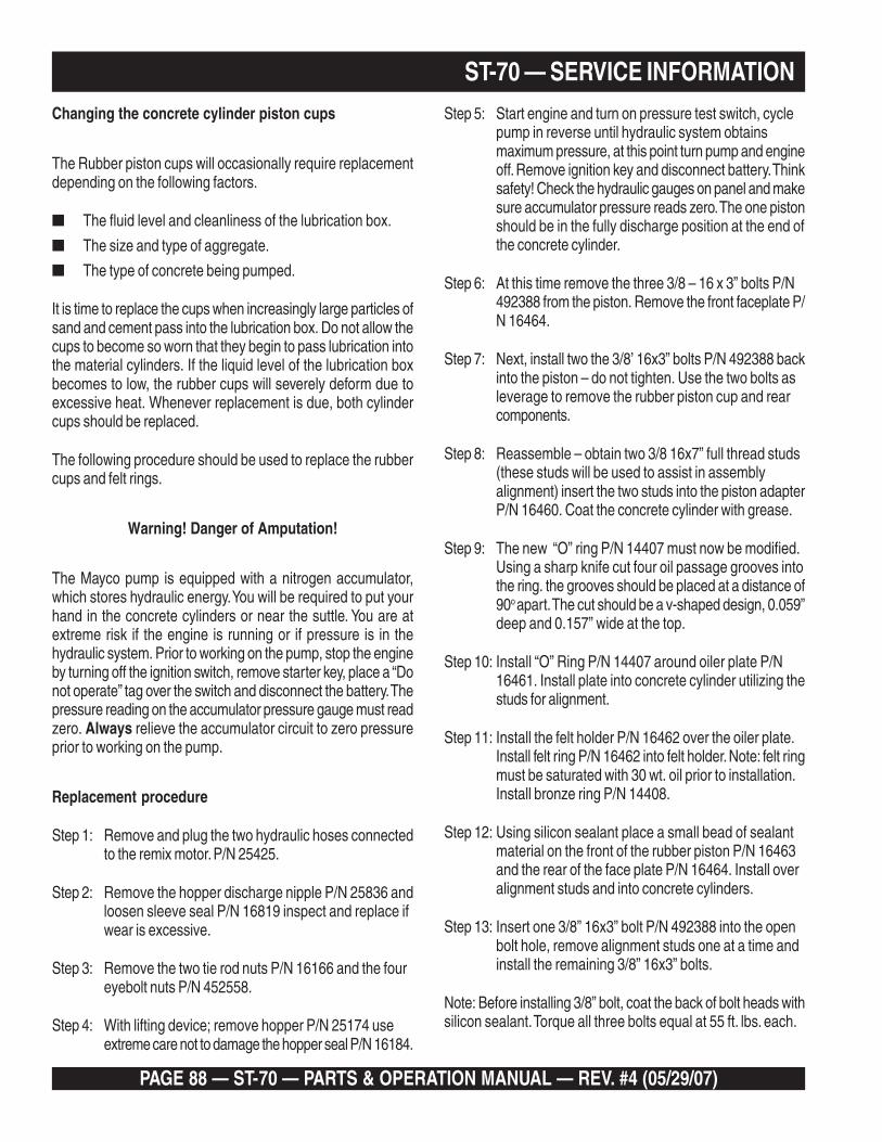
PAGE 88 — ST-70 — PARTS & OPERATION MANUAL — REV. #4 (05/29/07)
ST-70 — SERVICE INFORMATIONChanging the concrete cylinder piston cups
The Rubber piston cups will occasionally require replacementdepending on the following factors.
■ The fluid level and cleanliness of the lubrication box.
■ The size and type of aggregate.
■ The type of concrete being pumped.
It is time to replace the cups when increasingly large particles ofsand and cement pass into the lubrication box. Do not allow thecups to become so worn that they begin to pass lubrication intothe material cylinders. If the liquid level of the lubrication boxbecomes to low, the rubber cups will severely deform due toexcessive heat. Whenever replacement is due, both cylindercups should be replaced.
The following procedure should be used to replace the rubbercups and felt rings.
Warning! Danger of Amputation!
The Mayco pump is equipped with a nitrogen accumulator,which stores hydraulic energy. You will be required to put yourhand in the concrete cylinders or near the suttle. You are atextreme risk if the engine is running or if pressure is in thehydraulic system. Prior to working on the pump, stop the engineby turning off the ignition switch, remove starter key, place a “Donot operate” tag over the switch and disconnect the battery. Thepressure reading on the accumulator pressure gauge must readzero. Always relieve the accumulator circuit to zero pressureprior to working on the pump.
Replacement procedure
Step 1: Remove and plug the two hydraulic hoses connectedto the remix motor. P/N 25425.
Step 2: Remove the hopper discharge nipple P/N 25836 andloosen sleeve seal P/N 16819 inspect and replace ifwear is excessive.
Step 3: Remove the two tie rod nuts P/N 16166 and the foureyebolt nuts P/N 452558.
Step 4: With lifting device; remove hopper P/N 25174 useextreme care not to damage the hopper seal P/N 16184.
Step 5: Start engine and turn on pressure test switch, cyclepump in reverse until hydraulic system obtainsmaximum pressure, at this point turn pump and engineoff. Remove ignition key and disconnect battery. Thinksafety! Check the hydraulic gauges on panel and makesure accumulator pressure reads zero. The one pistonshould be in the fully discharge position at the end ofthe concrete cylinder.
Step 6: At this time remove the three 3/8 – 16 x 3” bolts P/N492388 from the piston. Remove the front faceplate P/N 16464.
Step 7: Next, install two the 3/8’ 16x3” bolts P/N 492388 backinto the piston – do not tighten. Use the two bolts asleverage to remove the rubber piston cup and rearcomponents.
Step 8: Reassemble – obtain two 3/8 16x7” full thread studs(these studs will be used to assist in assemblyalignment) insert the two studs into the piston adapterP/N 16460. Coat the concrete cylinder with grease.
Step 9: The new “O” ring P/N 14407 must now be modified.Using a sharp knife cut four oil passage grooves intothe ring. the grooves should be placed at a distance of90o apart. The cut should be a v-shaped design, 0.059”deep and 0.157” wide at the top.
Step 10: Install “O” Ring P/N 14407 around oiler plate P/N16461. Install plate into concrete cylinder utilizing thestuds for alignment.
Step 11: Install the felt holder P/N 16462 over the oiler plate.Install felt ring P/N 16462 into felt holder. Note: felt ringmust be saturated with 30 wt. oil prior to installation.Install bronze ring P/N 14408.
Step 12: Using silicon sealant place a small bead of sealantmaterial on the front of the rubber piston P/N 16463and the rear of the face plate P/N 16464. Install overalignment studs and into concrete cylinders.
Step 13: Insert one 3/8” 16x3” bolt P/N 492388 into the openbolt hole, remove alignment studs one at a time andinstall the remaining 3/8” 16x3” bolts.
Note: Before installing 3/8” bolt, coat the back of bolt heads withsilicon sealant. Torque all three bolts equal at 55 ft. lbs. each.

ST-70 — PARTS & OPERATION MANUAL — REV. #4 (05/29/07) — PAGE 89
ST-70 — SERVICE INFORMATION
Changing the wear plate and ring
Due to the swinging motion of the Nun-plate and the abrasivenature of concrete it is normal for the cutting ring to wear on theside that shears through the concrete inside the hopper. If thewear ring and wear plate do not fully seat against each other.The concrete slurry will pump into the hopper. This conditioncan be easily observed by the sudden change of the level ofconcrete inside the hopper during each stroke.
Warning! Danger of Amputation!
The Mayco pump is equipped with a nitrogen accumulator,which stores hydraulic energy. You will be required to put yourhand in the concrete cylinders or near the suttle. You are atextreme risk if the engine is running or if pressure is in thehydraulic system. Prior to working on the pump, stop the engineby turning off the ignition switch, remove starter key, place a “Donot operate” tag over the switch and disconnect the battery. Thepressure reading on the accumulator pressure gauge must readzero. Always relieve the accumulator circuit to zero pressureprior to working on the pump.
Replacement procedure
Step 1: Remove and plug the two hydraulic hoses connectedto the remix motor P/N 25425.
Step 2: Remove the hopper discharge nipple P/N 25836 andloosen sleeve seal P/N 16819 inspect and replace ifwear is excessive.
Step 3: Remove the two tie rod nuts P/N 16166 and the foureyebolts nuts P/N 452558.
Step 4: With a lifting devise, remove hopper P/N 25174 useextreme care nut to damage the hopper seal P/N 16184.
Step 5: Remove the four 5/8”-11 1 ½ “ bolts that hold the suttletube to the nun-plate and remove suttle tube. Theenergizer ring and wear ring will normally haveconcrete contamination holding them in position. It willbe required to chip some of the concrete loose to betterexpose the energizer ring. Using two small pry barsremove the energizer ring P/N 16816-1, insert ringP/N 16816-2 and wear ring P/N 16171.
Step 6: Clean out all concrete build up in and around the nun-plate area with a wire brush.
Step 7: Inspect the wear components for indications of wear.Note: it is typical that the wear plate P/N 25841 willhave two times the service life compared to the cuttingring. The wear plate has two wear surfaces. If itbecomes necessary to replace, the plate can bereversed to the opposite side to expose a new flatsurface. To replace or reverse the plate, remove thefive allen head counter suck bolts. Next remove thetwo cylinder “O” rings and clean the entire backsurface.
Step 8: Wear plate installation: install the two cylinder “O” ringsP/N 16174. Using silicon sealant, coat thecircumference of the concrete cylinders, wear plateback and around the five bolt holes. Next, install thewear plate and the five bolts. Note: the bolts must all beequally snugged and tightened to 100 foot poundseach.
Step 9: Wear ring installation: Install the wear ring P/N 16171into the nun plate. Install the insert ring P/N 16812-2inside of the rubber energizer ring P/N 16816-1. Installthe energizer ring assembly into the nun-plate.
After installing the above mentioned components the machinecan be re-assembled by reversing steps 1 through 5.
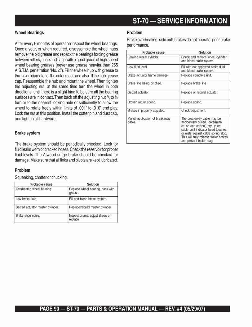
PAGE 90 — ST-70 — PARTS & OPERATION MANUAL — REV. #4 (05/29/07)
ST-70 — SERVICE INFORMATIONWheel Bearings
After every 6 months of operation inspect the wheel bearings.Once a year, or when required, disassemble the wheel hubsremove the old grease and repack the bearings forcing greasebetween rollers, cone and cage with a good grade of high speedwheel bearing greases (never use grease heavier than 265A.S.T.M. penetration “No. 2.”). Fill the wheel hub with grease tothe inside diameter of the outer races and also fill the hub greasecap. Reassemble the hub and mount the wheel. Then tightenthe adjusting nut, at the same time turn the wheel in bothdirections, until there is a slight bind to be sure all the bearingsurfaces are in contact. Then back off the adjusting nut 1/6 to ¼turn or to the nearest locking hole or sufficiently to allow thewheel to rotate freely within limits of .001” to .010” end play.Lock the nut at this position. Install the cotter pin and dust cap,and tighten all hardware.
Brake system
The brake system should be periodically checked. Look forfluid leaks worn or cracked hoses. Check the reservoir for properfluid levels. The Atwood surge brake should be checked fordamage. Make sure that all links and pivots are kept lubricated.
Problem
Squeaking, chatter or chucking.
Problem
Brake overheating, side pull, brakes do not operate, poor brakeperformance.
esuacelbaborP noituloS.gniraebleehwdetaehrevO htiwkcap,gniraebleehwecalpeR
.esaerg
.diulfekarbwoL .metsysekarbdeelbdnalliF
.rednilycretsamrotautcadezieS .rednilycretsamdliuber/ecalpeR
.esioneohsekarB roseohstsujda,smurdtcepsnI.ecalper
esuacelbaborP noituloS.rednilycleehwgnikaeL rednilycleehwecalperdnakcehC
.metsysekarbdeelbdna
.leveldiulfwoL diulfekarbdevorppatodhtiwlliF.metsysekarbdeelbdna
.egamademarfrotautcaekarB .tinuetelpmocecalpeR
.dehcnipgniebenilekarB enilekarbecalpeR
.rotautcadezieS .rotautcadliuberroecalpeR
.gnirpsnruternekorB .gnirpsecalpeR
.detsujdaylreporpmisekarB .tnemtsujdakcehC
yawakaerbfonoitacilppalaitraP.elbac
ebyamelbacyawakaerbehTenimreted(.dellupyllatnedicca
nopuyrp)tcerrocdnaesuacsehcuotdaebrotacidnilitnuelbac.potsgnirpselbactsniagastserrosekarbreliartesaelerylluflliwsihT
.gardreliarttneverpdna

ST-70 — PARTS & OPERATION MANUAL — REV. #4 (05/29/07) — PAGE 91
Effective: February 22, 2006 TERMS AND CONDITIONS OF SALE — PARTS
PAYMENT TERMS
Terms of payment for parts are net 30 days.
FREIGHT POLICY
All parts orders will be shipped collect orprepaid with the charges added to the invoice.All shipments are F.O.B. point of origin.Multiquip’s responsibility ceases when a signedmanifest has been obtained from the carrier,and any claim for shortage or damage must besettled between the consignee and the carrier.
MINIMUM ORDER
The minimum charge for orders from Multiquipis $15.00 net. Customers will be asked forinstructions regarding handling of orders notmeeting this requirement.
RETURNED GOODS POLICY
Return shipments will be accepted and creditwill be allowed, subject to the following provi-sions:
1. A Returned Material Authorization mustbe approved by Multiquip prior to ship-ment.
2. To obtain a Return Material Authorization,a list must be provided to Multiquip PartsSales that defines item numbers, quanti-ties, and descriptions of the items to bereturned.
a. The parts numbers and descriptionsmust match the current parts pricelist.
b. The list must be typed or computergenerated.
c. The list must state the reason(s) forthe return.
d. The list must reference the salesorder(s) or invoice(s) under which theitems were originally purchased.
e. The list must include the name andphone number of the person request-ing the RMA.
3. A copy of the Return Material Authoriza-tion must accompany the return shipment.
4. Freight is at the sender’s expense. Allparts must be returned freight prepaid toMultiquip’s designated receiving point.
5. Parts must be in new and resalable con-dition, in the original Multiquip package (ifany), and with Multiquip part numbersclearly marked.
6. The following items are not returnable:
a. Obsolete parts. (If an item is in theprice book and shows as being re-placed by another item, it is obsolete.)
b. Any parts with a limited shelf life(such as gaskets, seals, “O” rings,and other rubber parts) that were pur-chased more than six months prior tothe return date.
c. Any line item with an extended dealernet price of less than $5.00.
d. Special order items.
e. Electrical components.
f. Paint, chemicals, and lubricants.
g. Decals and paper products.
h. Items purchased in kits.
7. The sender will be notified of any materialreceived that is not acceptable.
8. Such material will be held for five workingdays from notification, pending instruc-tions. If a reply is not received within fivedays, the material will be returned to thesender at his expense.
9. Credit on returned parts will be issued atdealer net price at time of the originalpurchase, less a 15% restocking charge.
10. In cases where an item is accepted, forwhich the original purchase documentcan not be determined, the price will bebased on the list price that was effectivetwelve months prior to the RMA date.
11. Credit issued will be applied to futurepurchases only.
PRICING AND REBATES
Prices are subject to change without priornotice. Price changes are effective on a spe-cific date and all orders received on or after thatdate will be billed at the revised price. Rebatesfor price declines and added charges for priceincreases will not be made for stock on handat the time of any price change.
Multiquip reserves the right to quote and selldirect to Government agencies, and to OriginalEquipment Manufacturer accounts who useour products as integral parts of their ownproducts.
SPECIAL EXPEDITING SERVICE
A $35.00 surcharge will be added to the invoicefor special handling including bus shipments,insured parcel post or in cases where Multiquipmust personally deliver the parts to the carrier.
LIMITATIONS OF SELLER’S LIABILITY
Multiquip shall not be liable hereunder fordamages in excess of the purchase price of theitem with respect to which damages areclaimed, and in no event shall Multiquip beliable for loss of profit or good will or for anyother special, consequential or incidental dam-ages.
LIMITATION OF WARRANTIES
No warranties, express or implied, are madein connection with the sale of parts or tradeaccessories nor as to any engine not manufac-tured by Multiquip. Such warranties made inconnection with the sale of new, complete unitsare made exclusively by a statement of war-ranty packaged with such units, and Multiquipneither assumes nor authorizes any person toassume for it any other obligation or liabilitywhatever in connection with the sale of itsproducts. Apart from such written statement ofwarranty, there are no warranties, express,implied or statutory, which extend beyond thedescription of the products on the face hereof.

Discount Equipment Rental is your online resource for commercial and industrial quality equipment sales and rentals. We sell worldwide for the brands Genie, Terex, Stihl, JLG, Multiquip, Mayco, Stone, Diamond Products, Airman, Mustang, Power
Blanket. We have complete rental locations throughout Florida.
Locations:
West Palm Beach – 561-964-4949
Orlando – 407-291-3162
Tampa – 813-248-2848
Need parts? Check out our website at www.discount-equipment.com
Can’t find what you need? Click on this link http://www.discount-equipment.com/category/5443-parts/ and fill out the request form. Make sure you have your machines model and serial number available in order to help us get you the correct parts. One of our experienced staff members will get back to you with a quote for the right part that your machine needs.