Embed Size (px)
Citation preview

Model 432
Shake/Slush Freezers
Operating Instructions
053081-M
10/98
Complete this page for quick reference when service is required:
Taylor Distributor:
Address:
Phone:
Service:
Parts:
Date of Installation:
Information found on the data label:
Model Number:
Serial Number:
Electrical Specs: Voltage Cycle
Phase
Maximum Fuse Size: A
Minimum Wire Ampacity: A
E October, 1998 TaylorAll rights reserved.053081-M
The word Taylor and the Crown designare registered trademarks in the United Statesof America and certain other countries.
Taylor Companya division of Carrier Commercial Refrigeration, Inc.750 N. Blackhawk Blvd.Rockton, IL 61072

Table of Contents Model 432
Table of Contents
Section 1 To the Installer 1. . . . . . . . . . . . . . . . . . . . . . . . . . . . . . . . . . . . . . . . . . . .
Installer Safety 1. . . . . . . . . . . . . . . . . . . . . . . . . . . . . . . . . . . . . . . . . . . . . . . . . . . . . . . .
Site Preparation 1. . . . . . . . . . . . . . . . . . . . . . . . . . . . . . . . . . . . . . . . . . . . . . . . . . . . . . .
Air Cooled Units 1. . . . . . . . . . . . . . . . . . . . . . . . . . . . . . . . . . . . . . . . . . . . . . . . . . . . . . .
Electrical Connections 2. . . . . . . . . . . . . . . . . . . . . . . . . . . . . . . . . . . . . . . . . . . . . . . . .
Beater Rotation 2. . . . . . . . . . . . . . . . . . . . . . . . . . . . . . . . . . . . . . . . . . . . . . . . . . . . . . .
Refrigerant 3. . . . . . . . . . . . . . . . . . . . . . . . . . . . . . . . . . . . . . . . . . . . . . . . . . . . . . . . . . .
Section 2 To the Operator 4. . . . . . . . . . . . . . . . . . . . . . . . . . . . . . . . . . . . . . . . . . .
Compressor Warranty Disclaimer 4. . . . . . . . . . . . . . . . . . . . . . . . . . . . . . . . . . . . . . .
Section 3 Safety 5. . . . . . . . . . . . . . . . . . . . . . . . . . . . . . . . . . . . . . . . . . . . . . . . . . . .
Section 4 Operator Parts Identification 7. . . . . . . . . . . . . . . . . . . . . . . . . . . . . . .
Model 432 7. . . . . . . . . . . . . . . . . . . . . . . . . . . . . . . . . . . . . . . . . . . . . . . . . . . . . . . . . . . .
Beater Door Assembly 8. . . . . . . . . . . . . . . . . . . . . . . . . . . . . . . . . . . . . . . . . . . . . . . . .
Accessories 10. . . . . . . . . . . . . . . . . . . . . . . . . . . . . . . . . . . . . . . . . . . . . . . . . . . . . . . . . .
Section 5 Important: To the Operator 11. . . . . . . . . . . . . . . . . . . . . . . . . . . . . . . . .
Control Switch (Item 1) 11. . . . . . . . . . . . . . . . . . . . . . . . . . . . . . . . . . . . . . . . . . . . . . . . .
Push--Button Switch (Item 2) 11. . . . . . . . . . . . . . . . . . . . . . . . . . . . . . . . . . . . . . . . . . . .
Display Light Switch (Item 3) 11. . . . . . . . . . . . . . . . . . . . . . . . . . . . . . . . . . . . . . . . . . . .
Indicator Light -- “Mix Out” (Item 4) 12. . . . . . . . . . . . . . . . . . . . . . . . . . . . . . . . . . . . . .
Indicator Light -- “Add Mix” (Item 5) 12. . . . . . . . . . . . . . . . . . . . . . . . . . . . . . . . . . . . . .
Viscosity Adjustment (Item 6) 12. . . . . . . . . . . . . . . . . . . . . . . . . . . . . . . . . . . . . . . . . . .
Section 6 Operating Procedures 13. . . . . . . . . . . . . . . . . . . . . . . . . . . . . . . . . . . . .
Assembly 13. . . . . . . . . . . . . . . . . . . . . . . . . . . . . . . . . . . . . . . . . . . . . . . . . . . . . . . . . . . .
Sanitizing 17. . . . . . . . . . . . . . . . . . . . . . . . . . . . . . . . . . . . . . . . . . . . . . . . . . . . . . . . . . . .
Priming 18. . . . . . . . . . . . . . . . . . . . . . . . . . . . . . . . . . . . . . . . . . . . . . . . . . . . . . . . . . . . . .

Model 432 Table of Contents
Table of Contents -- Page 2
Closing Procedure 18. . . . . . . . . . . . . . . . . . . . . . . . . . . . . . . . . . . . . . . . . . . . . . . . . . . .
Draining Product From The Freezing Cylinder 18. . . . . . . . . . . . . . . . . . . . . . . . . . . .
Rinsing 19. . . . . . . . . . . . . . . . . . . . . . . . . . . . . . . . . . . . . . . . . . . . . . . . . . . . . . . . . . . . . .
Cleaning 19. . . . . . . . . . . . . . . . . . . . . . . . . . . . . . . . . . . . . . . . . . . . . . . . . . . . . . . . . . . . .
Disassembly 19. . . . . . . . . . . . . . . . . . . . . . . . . . . . . . . . . . . . . . . . . . . . . . . . . . . . . . . . . .
Brush Cleaning 20. . . . . . . . . . . . . . . . . . . . . . . . . . . . . . . . . . . . . . . . . . . . . . . . . . . . . . .
Section 7 Important: Operator Checklist 21. . . . . . . . . . . . . . . . . . . . . . . . . . . . . .
During Cleaning and Sanitizing: 21. . . . . . . . . . . . . . . . . . . . . . . . . . . . . . . . . . . . . . . . .
Troubleshooting Bacterial Count: 21. . . . . . . . . . . . . . . . . . . . . . . . . . . . . . . . . . . . . . . .
Regular Maintenance Checks: 21. . . . . . . . . . . . . . . . . . . . . . . . . . . . . . . . . . . . . . . . . .
Winter Storage 22. . . . . . . . . . . . . . . . . . . . . . . . . . . . . . . . . . . . . . . . . . . . . . . . . . . . . . . .
Section 8 Troubleshooting Guide 23. . . . . . . . . . . . . . . . . . . . . . . . . . . . . . . . . . . .
Section 9 Parts Replacement Schedule 25. . . . . . . . . . . . . . . . . . . . . . . . . . . . . . .
Section 10 Parts List 26. . . . . . . . . . . . . . . . . . . . . . . . . . . . . . . . . . . . . . . . . . . . . . . . .
Wiring Diagrams 31. . . . . . . . . . . . . . . . . . . . . . . . . . . . . . . . . . . . . . . . . . . . . . . . . . . . . .
Note: Continuing research results in steady improvements; therefore, informationin this manual is subject to change without notice.
E October, 1998 TaylorAll rights reserved.053081-M
The word Taylor and the Crown designare registered trademarks in the United Statesof America and certain other countries.
Taylor Companya division of Carrier Commercial Refrigeration, Inc.750 N. Blackhawk Blvd.Rockton, IL 61072

1Model 432 To the Installer081208
Section 1 To the Installer
The following are general installation instructions. Forcomplete installation details, please see the check outcard.
Installer Safety
In all areas of the world, equipment should beinstalled in accordance with existing local codes.Please contact your local authorities if you have anyquestions.
Care should be taken to ensure that all basic safetypractices are followed during the installation andservicing activities related to the installation andservice of Taylor equipment.
S Only authorized Taylor service personnelshould perform installation and repairs onthe equipment.
S Authorized service personnel should consultOSHA Standard 29CFRI910.147 or theapplicable code of the local area for theindustry standards on lockout/tagoutprocedures before beginning any installationor repairs.
S Authorized service personnel must ensurethat the proper PPE is available and wornwhen required during installation andservice.
S Authorized service personnel must removeall metal jewelry, rings, and watches beforeworking on electrical equipment.
The main power supply(s) to the freezer mustbe disconnected prior to performing any repairs.Failure to follow this instruction may result in personalinjury or death from electrical shock or hazardousmoving parts as well as poor performance or damageto the equipment.
Note: All repairs must be performed by anauthorized Taylor Service Technician.
This unit has many sharp edges that cancause severe injuries.
Site Preparation
Review the area the unit is to be installed in beforeuncrating the unit making sure that all possiblehazards the user or equipment may come into havebeen addressed.
For IndoorUseOnly: This unit is designed to operateindoors, under normal ambient temperatures of70_-75_F (21_-24_C). The freezer has successfullyperformed in high ambient temperatures of104_(40_C) at reduced capacities.
This unit must NOT be installed in an areawhere a water jet or hose can be used. NEVER use awater jet or hose to rinse or clean the unit. Failure tofollow this instruction may result in electrocution.
This unit must be installed on a level surfaceto avoid the hazard of tipping. Extreme care should betaken in moving this equipment for any reason. Two ormore persons are required to safely move this unit.Failure to comply may result in personal injury orequipment damage.
Uncrate the unit and inspect it for damage. Report anydamage to your Taylor Distributor.
This piece of equipment is made in the USA and hasUSA sizes of hardware. All metric conversions areapproximate and vary in size.
Air Cooled Units
DO NOT obstruct air intake and discharge openings:
A minimum of 6” (152 mm) on both sides and 0” on theback is required. Failure to follow this instruction maycause poor freezer performance and damage to themachine.

2To the Installer Model 432
080911
Electrical ConnectionsThis unit must be plugged into a properly groundedreceptacle. The cord and plug must be sized for 20Amp usage. The voltage specifications are208--230/60/1. Follow specifications listed on yourdata plate.
FOLLOW YOUR LOCAL ELECTRICAL CODES!
In the United States, this equipment is intended to beinstalled in accordance with the National ElectricalCode (NEC), ANSI/NFPA 70--1987. The purpose ofthe NEC code is the practical safeguarding of personsand property from hazards arising from the use ofelectricity. This code contains provisions considerednecessary for safety. Compliance therewith andproper maintenance will result in an installationessentially free from hazard!
In all other areas of the world, equipment should beinstalled in accordance with the existing local codes.Please contact your local authorities.
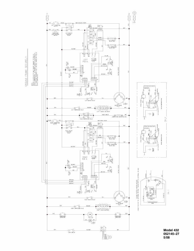
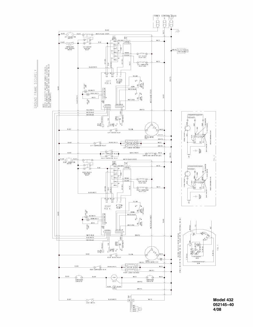
Each unit requires one power supply for each datalabel on the unit. Check the data label on the freezerfor fuse, circuit ampacity and other electricalspecifications. Refer to the wiring diagram providedinside of the electrical box, for proper powerconnections.
CAUTION: THIS EQUIPMENT MUST BEPROPERLY GROUNDED! FAILURE TO DO SOCAN RESULT IN SEVERE PERSONAL INJURYFROM ELECTRICAL SHOCK!
This unit is provided with an equipotentialgrounding lug that is to be properly attached to the rearof the frameby the authorized installer. The installationlocation is marked by the equipotential bondingsymbol (5021 of IEC 60417-1) on both the removablepanel and the equipments frame.
S Stationary appliances which are notequipped with a power cord and a plug oranother device to disconnect the appliancefrom the power source must have an all-poledisconnecting device with a contact gap ofat least 3mm installed in the externalinstallation.
S Appliances that are permanently connectedto fixed wiring and for which leakagecurrents may exceed 10 mA, particularlywhen disconnected or not used for longperiods, or during initial installation, shallhave protective devices such as a GFI, toprotect against the leakage of current,installed by the authorized personnel to thelocal codes.
S Supply cords used with this unit shall beoil-resistant, sheathed flexible cable notlighter than ordinary polychloroprene orother equivalent syntheticelastomer-sheathed cord (Code designation60245 IEC 57) installed with the proper cordanchorage to relieve conductors from strain,including twisting, at the terminals andprotect the insulation of the conductors fromabrasion.
Beater Rotation
Beater rotation must be clockwise as viewedlooking into the freezing cylinder.
Note: The following procedures must beperformed by an authorized Taylor servicetechnician.
To correct rotation on a single--phase unit, change theleads inside the beater motor. (Follow the diagramprinted on motor.)

3Model 432 To the Installer080911
Refrigerant
In consideration of our environment, Taylorproudly uses only earth friendly HFC refrigerants. TheHFC refrigerant used in this unit is R404A. Thisrefrigerant is generally considered non-toxic andnon-flammable, with an Ozone Depleting Potential(ODP) of zero (0).
However, any gas under pressure is potentiallyhazardous and must be handled with caution.
NEVER fill any refrigerant cylinder completely withliquid. Filling the cylinder to approximately 80% willallow for normal expansion.
Refrigerant liquid sprayed onto the skin maycause serious damage to tissue. Keep eyes and skinprotected. If refrigerant burns should occur, flushimmediately with cold water. If burns are severe, applyice packs and contact a physician immediately.
Taylor reminds technicians to be cautious ofgovernment laws regarding refrigerant recovery,recycling, and reclaiming systems. If you have anyquestions regarding these laws, please contact thefactory Service Department.
WARNING: R404A refrigerant used inconjunction with polyolester oils is extremely moistureabsorbent. When opening a refrigeration system, themaximum time the system is openmust not exceed 15minutes. Cap all open tubing to prevent humid air orwater from being absorbed by the oil.

4To the Operator Model 432
080623
Section 2 To the Operator
The freezer you have purchased has been carefullyengineered andmanufactured to give you dependableoperation. The Taylor Model 432, when properlyoperated and cared for, will produce a consistentquality product. Like all mechanical products, they willrequire cleaning and maintenance. A minimumamount of care and attention is necessary if theoperating procedures outlined in this manual arefollowed closely.
This Operator’s Manual should be read beforeoperating or performing any maintenance on yourequipment.
Your Taylor freezer will NOT eventually compensatefor and correct any errors during the set--up or fillingoperations. Thus, the initial assembly and primingprocedures are of extreme importance. It is stronglyrecommended that personnel responsible for theequipment’s operation, both assembly anddisassembly, sit down together and go through theseprocedures in order to be properly trained and tomakesure that no misunderstandings exist.
In the event you should require technical assistance,please contact your local authorized TaylorDistributor.
Note: Warranty is valid only if the parts are authorizedTaylor parts, purchased from an authorized TaylorDistributor, and the required service work is providedby an authorized Taylor service technician. Taylorreserves the right to deny warranty claims onequipment or parts if non--approved parts orrefrigerant were installed in the machine, systemmodifications were performed beyond factoryrecommendations, or it is determined that the failurewas caused by neglect or abuse.
Note: Constant research results in steadyimprovements; therefore, information in thismanual is subject to change without notice.
If the crossed out wheeled bin symbol isaffixed to this product, it signifies that this product iscompliant with the EUDirective as well as other similarlegislation in effect after August 13, 2005. Therefore,it must be collected separately after its use iscompleted, and cannot be disposed as unsortedmunicipal waste.
The user is responsible for returning the product to theappropriate collection facility, as specified by your localcode.
For additional information regarding applicable locallaws, please contact the municipal facility and/or localdistributor.
Compressor Warranty Disclaimer
The refrigeration compressor(s) on this machine arewarranted for the term indicated on the warranty cardaccompanying this machine. However, due to theMontreal Protocol and the U.S. Clean Air ActAmendments of 1990, many new refrigerants arebeing tested and developed, thus seeking their wayinto the service industry. Some of these newrefrigerants are being advertised as drop--inreplacements for numerous applications. It should benoted that, in the event of ordinary service to thismachine’s refrigeration system, only the refrigerantspecified on the affixed data label should beused.The unauthorized use of alternate refrigerants will voidyour compressor warranty. It will be the owner’sresponsibility tomake this fact known to any technicianhe employs.
It should also be noted that Taylor does not warrant therefrigerant used in its equipment. For example, if therefrigerant is lost during the course of ordinary serviceto this machine, Taylor has no obligation to eithersupply or provide its replacement either at billable orunbillable terms. Taylor does have the obligation torecommend a suitable replacement if the originalrefrigerant is banned, obsoleted, or no longer availableduring the five year warranty of the compressor.
Taylor will continue to monitor the industry and testnew alternates as they are being developed. Should anew alternate prove, through our testing, that it wouldbe accepted as a drop--in replacement, then theabovedisclaimer would become null and void. To find out thecurrent status of an alternate refrigerant as it relates toyour compressor warranty, call the local TaylorDistributor or the Taylor Factory. Be prepared toprovide the Model/Serial Number of the unit inquestion.

5Model 432 Safety080911
Section 3 Safety
Weat Taylor Company are concernedabout the safetyof the operator when he or she comes in contact withthe freezer and its parts. Taylor has gone to extremeefforts to design and manufacture built--in safetyfeatures to protect both youand the service technician.As an example, warning labels have been attached tothe freezer to further point out safety precautions to theoperator.
IMPORTANT -- Failure to adhere to thefollowing safety precautions may result in severepersonal injury or death. Failure to comply withthese warnings may damage the machine and itscomponents. Component damage will result inpart replacement expense and service repairexpense.
DONOT operate the freezer without readingthis Operator Manual. Failure to follow this instructionmay result in equipment damage, poor freezerperformance, health hazards, or personal injury.
This unit is provided with an equipotentialgrounding lug that is to be properly attached to the rearof the frameby the authorized installer. The installationlocation is marked by the equipotential bondingsymbol (5021 of IEC 60417-1) on both the removablepanel and the equipments frame.
DO NOT use a water jet to clean or rinse thefreezer. Failure to follow these instructions may resultin serious electrical shock.
S DO NOT operate the freezer unless it isproperly grounded.
S DO NOT operate the freezer with largerfuses than specified on the freezer datalabel.
S DO NOT attempt any repairs unless themain power supply to the freezer has beendisconnected. Contact your local authorizedTaylor Distributor for service.
S Stationary appliances which are notequipped with a power cord and a plug oranother device to disconnect the appliancefrom the power source must have an all-poledisconnecting device with a contact gap ofat least 3mm installed in the externalinstallation.
S Appliances that are permanently connectedto fixed wiring and for which leakagecurrents may exceed 10 mA, particularlywhen disconnected or not used for longperiods, or during initial installation, shallhave protective devices such as a GFI, toprotect against the leakage of current,installed by the authorized personnel to thelocal codes.
S Supply cords used with this unit shall beoil-resistant, sheathed flexible cable notlighter than ordinary polychloroprene orother equivalent syntheticelastomer-sheathed cord (Code designation60245 IEC 57) installed with the proper cordanchorage to relieve conductors from strain,including twisting, at the terminals andprotect the insulation of the conductors fromabrasion.
Failure to follow these instructions may result inelectrocution. Contact your local authorized TaylorDistributor for service.

6Safety Model 432
080911
S DO NOT allow untrained personnel tooperate this machine.
S DO NOT operate the freezer unless allservice panels and access doors arerestrained with screws.
S DO NOT remove any internal operatingparts (examples: freezer door, beater,scraper blades, etc.) unless all controlswitches are in the OFF position.
Failure to follow these instructionsmay result in severepersonal injury to fingers or hands from hazardousmoving parts.
This unit has many sharp edges that cancause severe injuries.
S DO NOT put objects or fingers in the doorspout. This may contaminate the productand cause severe personal injury from bladecontact.
S USE EXTREME CAUTION when removingthe beater asssembly. The scraper bladesare very sharp.
This freezer must be placed on a levelsurface. Failure to complymay result in personal injuryor equipment damage.
Cleaning and sanitizing schedules aregoverned by your state or local regulatory agenciesand must be followed accordingly. Please refer to thecleaning section of this manual for the properprocedure to clean this unit.
DO NOT obstruct air intake and discharge openings:
A minimum of 6” (152 mm) on both sides and 0” on theback is required. Failure to follow this instruction maycause poor freezer performance and damage to themachine.
For Indoor UseOnly: This unit is designed to operateindoors, under normal ambient temperatures of 70_ -75_F (21_ - 24_C). The freezer has successfullyperformed in high ambient temperatures of104_(40_C) at reduced capacities.
NOISE LEVEL: Airborne noise emission does notexceed 78 dB(A) when measured at a distance of 1.0meter from the surface of the machine and at a heightof 1.6 meters from the floor.

7Model 432 Operator Parts Identification
Section 4 Operator Parts Identification
Model 432
Item Description Part No.
1 Cover A.--Hopper X52452
2 Panel--Rear 052363
*3 Panel--Side--Right--Louvered 052527
4 Panel--Front--Lower 052361
5 Gasket--Base Pan 052377
6 Tray A.--Drip X46848
7 Shield--Splash 046851
8 Pan--Drip 17--1/4” Long 027504
Item Description Part No.
9 Stud--Nose Cone 5/16--18x5/16--18 013496
10 Panel--Front--Upper 052360
†10a Gasket--Insulator 052617
11 Bulb--Light--Fluorescent U--Shape 045445
12 Bracket--Light 052243
13 Lens--Decorative Plate 052359
14 Panel--Side--Left 052362
15 Shelf--Drip Tray 052065
*J8070000/Up -- Refer to Parts List at end of manual.†Not Shown.
8Operator Parts Identification Model 432
090729
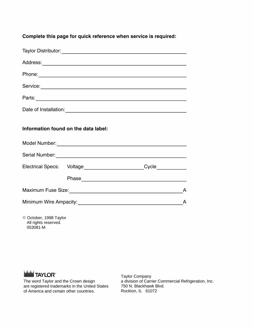
Beater Door Assembly
Figure 1

9Model 432 Operator Parts Identification081001
Beater Door Assembly Parts Identification
ITEM DESCRIPTION PART NO.
1 DOOR A. - PARTIAL X392482 HANDLE A. DRAW X473843 NUT-STUD 0436664 BUSTER - ICE 0477355 O-RING - 1" OD X .139 W 0325046 VALVE DRAW - SLUSH - ICE
BUSTER047734
7 VALVE A. - HANDLE PIN X259298 O-RING - .291 OD X .080 W 0185509 ARM - TORQUE 052450
10 TORQUE ASSEMBLY X50382
ITEM DESCRIPTION PART NO.
11 BEARING - GUIDE 01449612 CLIP - SCRAPER BLADE 04623813 BLADE - SCRAPER PLASTIC 04623714 GASKET - DOOR 5.109" ID X
5.630014030
15 BEARING - FRONT 01311616 BEATER A. - 4 QT. 1 PIN X4949017 SHAFT - BEATER 03541818 SEAL - DRIVE SHAFT 03256019 O-RING 7/8 OD X .139 W 025307

10Operator Parts Identification Model 432
080508
Accessories
Item Description Part No.
1 Kit A.--Tune Up X39969
2 Brush--Mix Pump Body 3” x 7” 023316
3 Pail--Mix 10 Qt. 013163
4 Brush--Double Ended 013072
5 Brush--Rear Bearing 1” x 2” x 14” 013071
Item Description Part No
6 Brush--Draw Valve 1--1/2” x 3” 014753
7 Lubricant--Taylor 047518
8 Sanitizer -- Kay 5 (125 Packets) 041082
*9 Panel A.--Air Guide X52521
*Prior to S/N J8070000.(Note: Optional Field Kit X52633 for S/N J8070000/Up.)

11Model 432 Important: To the Operator
Section 5 Important: To the Operator
Item Description
1 Switch--Toggle -- 3 PDT
2 Switch--Push Button -- SPST
3 Switch--Toggle--SPST -- 3/4 HP/250 V
4 Light--Amber--Rect. -- 12 VDC -- MIX OUT
5 Light--Amber--Rect. -- 12 VDC -- ADD MIX
6 Viscosity Adjustment
The following chart identifies the symbol definitionsused on the operator switches.
= The “ON/AUTO” button.
= The “OFF” button.
= The “WASH” button.
Control Switch (Item 1)The center position is “OFF”. The left position is“WASH”, which activates only the beater motor. Theright position is “AUTO”, which activates the beatermotor and the refrigeration system.
Push--Button Switch (Item 2)If an overload condition occurs, the freezer willautomatically stop operating. To properly reset thefreezer, place the toggle switch in the “OFF” position.Wait two or threeminutes; then press the push--buttonswitch. Place the power switch in the “WASH” positionand observe the freezer’s performance. Place thepower switch in the “AUTO” position.
Note: If the freezer is unplugged from the wallreceptacle, it will be necessary to press thepush--button switch for the freezer to operate oncepower is re--established.
Display Light Switch (Item 3)The display light switch is located under the controlchannel. The left position is “OFF”. The right positionis “ON”, and activates the display light.

12Important: To the Operator Model 432
Indicator Light -- “Mix Out” (Item 4)A mix out indicating light is located on the front of themachine.When the light is flashing, it indicates that thehopper is empty and the mix supply needsreplenishing. To prevent damage to the unit,refrigeration discontinues automatically when the mixout indicator lights illuminates. Refrigerationwill restart30 seconds after the mix supply is replenished.
Indicator Light -- “Add Mix” (Item 5)Amix level indicating light is located on the front of themachine.When the light is flashing, it indicates that themix hopper has a low supply of product and should berefilled as soon as possible.
Viscosity Adjustment (Item 6)The viscosity (thickness) of the slush can be adjustedby turning the viscosity adjustment screw locatedunder the control channel. Turn the viscosityadjustment screw clockwise for a thicker product, orcounterclockwise for a thinner product. After makingan adjustment, allow the refrigeration system to cycle2 or 3 times to accurately evaluate the viscosity.

13Model 432 Operating Procedures
Section 6 Operating Procedures
The Model 432 freezer is designed to produce shakeor slush product at the desired thickness. This unit hasa 4 quart freezing cylinder.
We begin our instructions at the point where we enterthe store in the morning and find the partsdisassembled and laid out to air dry from the previousnight’s brush cleaning.
These opening procedures will show you how toassemble these parts into the freezer, sanitize them,and prime the freezer with fresh mix in preparation toserve your first portion.
If you are disassembling the machine for the first timeor need information to get to this point in ourinstructions, turn to page 19, “Disassembly”, and startthere.
AssemblyNote: When lubricating parts, use an approved foodgrade lubricant (example: Taylor Lube).
Step 1Lubricate the groove on the drive shaft and slide theo--ring in place. Lubricate the o--ring and shaft portionthat comes in contact with the bearing. DO NOTlubricate the square end of the drive shaft. Lubricatethe boot seal groove and slide the boot seal over theshaft and groove until it snaps into place. Fill the insideportion of the seal with 1/4” more lubricant and evenlylubricate the end of the seal that fits onto the rear shellbearing.
Figure 1
Note: Do not install the boot seal inside out.
Install the drive shaft. Insert the beater drive shaft intothe rear shell bearing and engage the square endfirmly into the female socket of the drive unit. Becertain that the drive shaft fits into the drive couplingwithout binding.
Figure 2
Step 2Install the beater assembly. First check the scraperblade for any nicks or signs of wear. If any nicks arepresent, replace the blade. If the blade is in goodcondition, place the clip over the blade and install theblade and clip on the beater assembly. Be sure theholes in the blade and the clip are securely positionedover the beater pin.
Figure 3

14Operating Procedures Model 432
Holding the beater securely, slide the beater into thefreezing cylinder and align the hole at the rear of thebeater with the flats on the end of the drive shaft.
Slide the beater the remainder of the way into thefreezing cylinder and over the end of the drive shaft.The beater assembly will not protrudebeyond the frontof the freezing cylinder.
Figure 4
Step 3Install the white plastic guide bearing on the short endof the torque rotor. Slide the o--ring into the groove onthe long end of the torque rotor and lubricate theo--ring. Do not lubricate the guide bearing.
Figure 5
Step 4Insert the torque rotor end with the guide bearing intothe pilot hole in the center of the drive shaft. The holein the torque rotor shaft should be rotated to the 12o’clock position.
Figure 6
Step 5Assemble the freezer door with the “Ice Buster” (doorspout clearing device). To assemble the door with theice buster, install the o--rings on the draw valve andlubricate.
Figure 7
Insert the draw valve into the door, leavingapproximately half of the valve sticking out the top ofthe door.
Figure 8

15Model 432 Operating Procedures
Rotate thedrawvalve so the flats on the topof thedrawvalve are perpendicular to the door face.
Figure 9
Insert the ice buster through the door spout and intothe slot located just above the lower o--ring.
Figure 10
With the ice buster in place, rotate the draw valve toallow installation of the draw handle. This will lock theice buster in place. Install the draw handle pin, andclose the draw valve by moving the handle to the left.
Figure 11
Place the large rubber gasket into the groove on theback side of the freezer door. Slide the white, plasticfront bearing onto the bearing hub, making certain thatthe flanged end of the bearing is resting against thefreezer door. DO NOT lubricate the door gasket orfront bearing.
Figure 12
Step 6Install the door on the four studs on the front of thefreezing cylinder. Install the four handscrews on thedoor, and tighten them equally in a criss--crossmanner.
Figure 13

16Operating Procedures Model 432
Step 7Position the torque arm by inserting it through the slotin the torque switch arm and down into the hole in thetorque rotor which protrudes from the door. Verifyproper installation bymoving the torque rotor back andforth to be sure it moves freely and easily.
Figure 14
Step 8Install the front drip pans. Slide the long drip pans intothe holes in the front panel.
Figure 15
Step 9Install the front drip tray and splash shield beneath thedoor spouts.
Figure 16
Step 10Lay the air/mix feed tube (optional) in the bottom of themix hopper.
Figure 17
Repeat these steps for the other side of the unit.

17Model 432 Operating Procedures
SanitizingStep 1Prepare an approved 100 PPM sanitizing solution(examples: 2--1/2 gal. [9.5 liters] of Kay--5R or 2gal. [7.6 liters] of Stera--SheenR). USE WARMWATER AND FOLLOW THE MANUFACTURER’SSPECIFICATIONS.
Step 2Pour the sanitizing solution into the hopper and allowit to flow into the freezing cylinder.
Figure 18
Step 3While the solution is flowing into the freezing cylinder,brush clean the mix hopper, air/mix feed tube(optional) and mix inlet hole.
Step 4Place the power switch in the “WASH” position. Thiswill agitate the sanitizing solution in the freezingcylinder. Allow the solution to agitate for five minutes.
Figure 19
Step 5Place an empty mix pail beneath the door spout andmove the draw handle to the right. Draw off all thesanitizing solution. When the sanitizer stops flowingfrom the door spout, move the draw handle to the leftand place the control switch in the “OFF” position.
Figure 20
Step 6Stand the air/mix feed tube (optional) in the corner ofthe hopper.
Figure 21
Repeat these steps for the other side of the unit.

18Operating Procedures Model 432
Priming
Step 1With a pail beneath the door spout, move the drawhandle to the right. Pour two gallons (7.6 liters) ofFRESHmix into the hopper and allow it to flow into thefreezing cylinder. This will force out any remainingsanitizing solution. When full strength mix is flowingfrom the door spout, move the draw handle to the left.
Step 2When the mix has stopped bubbling down into thefreezing cylinder, install the air/mix feed tube (optional)in the mix inlet hole with the hole side down.
Figure 22
Step 3Place the power switch in the “AUTO” position. Whenthe unit cycles off, the product will be at servingviscosity. The viscosity (thickness) of the slush can beadjusted by turning the viscosity adjustment screwlocated under the control channel. Turn the viscosityadjustment screw clockwise for a thicker product, orcounterclockwise for a thinner product. After makingan adjustment, allow the refrigeration system to cycle2 or 3 times to accurately evaluate the viscosity.
Figure 23
Note: To identify the viscosity adjustment screw, seeillustration on page 11.
Step 4Place the mix hopper cover in position. Periodically,during the day’s operation, check to be sure there is asufficient amount of mix in the hopper.
Figure 24
Repeat these steps for the other side of the unit.
Closing Procedure
To disassemble this unit, the following items will beneeded:
S Two cleaning pails
S Necessary brushes (provided with freezer)
S Cleaner
S Single service towels
Draining Product From TheFreezing Cylinder
Step 1Place the power switch in the “OFF” position as farahead of cleaning time as possible to allow frozenproduct to soften for easier cleaning.
Step 2Raise the hopper cover. If the unit is equipped with anair/mix feed tube, take it to the sink for cleaning.

19Model 432 Operating Procedures080911
Step 3If local health codes permit the use of rerun, placea sanitized, NSF approved stainless steel reruncontainer beneath the door spout. Place the powerswitch in the “WASH” position and move the drawhandle to the right. When all the product stops flowingfrom the door spout, move the draw handle to the leftand place the power switch in the “OFF” position.Place the sanitized lid on the rerun container andplaceit in the walk--in cooler.
Note: If local health codesDONOTpermit theuseof rerun, the productmust bediscarded. Follow theinstructions in the previous step, except drain theproduct into a mix pail and properly discard the mix.
ALWAYS FOLLOW LOCAL HEALTH CODES.
Repeat these steps for the other side of the unit.
RinsingStep 1Pour twogallons (7.6 liters) of cool, cleanwater into themix hopper. With the brushes provided, scrub the mixhopper and the mix inlet hole.
Figure 25
Step 2With a pail beneath the door spout, place the powerswitch in the “WASH” position and move the drawhandle to the right. Drain all the rinse water from thefreezing cylinder. When the rinse water stops flowingfrom the door spout, move the draw handle to the leftand place the control switch in the “OFF” position.
Repeat this procedure until the rinse water beingdrawn from the freezing cylinder is clear.
Repeat these steps for the other side of the unit.
Cleaning
Step 1Prepare an approved 100 PPM cleaning solution(examples: 2--1/2 gal. [9.5 liters] of Kay--5R or 2gal. [7.6 liters] of Stera--SheenR). USE WARMWATER AND FOLLOW THE MANUFACTURER’SSPECIFICATIONS.
Step 2Pour the cleaning solution into the hopper and allow itto flow into the freezing cylinder.
Step 3While the solution is flowing into the freezing cylinder,brush--clean the mix hopper and mix inlet hole.
Step 4Place the power switch in the “WASH” position. Thiswill agitate the cleaning solution in the freezingcylinder.
Step 5Place an empty pail beneath the door spout and movethe draw handle to the right. Draw off all the cleaningsolution.When the solution stops flowing from thedoorspout, move the draw handle to the left, and place thepower switch in the “OFF” position.
Repeat these steps for the other side of the unit.
Disassembly
Step 1BE SURE THE CONTROL SWITCH IS IN THE“OFF” POSITION.
Step 2Remove the handscrews, freezer door, beaterassembly, torque rotor, scraper blade and drive shaftfrom the freezing cylinder. Take these parts to the sinkfor cleaning.
Step 3Remove the front drip tray and the splash shield. Takethese parts to the sink for cleaning.
Step 4Remove the rear drip pans from the front panel. Note:If the drip pans are filled with an excessive amount ofmix, it is an indication the drive shaft seals should bereplaced or properly lubricated.
Repeat these steps for the other side of the unit.
20Operating Procedures Model 432
Brush Cleaning
Step 1Prepare a sink with a cleaning solution (examples:Kay--5R or Stera--SheenR). USE WARM WATERAND FOLLOW THE MANUFACTURER’S SPECIFI-CATIONS. (If another approved cleaner is used, diluteaccording to label instructions. IMPORTANT: Followthe label directions. Too STRONG of a solution cancause parts damage, while too MILD of a solution willnot provide adequate cleaning.) Make sure all brushesprovided with the freezer are available for brushcleaning.
Step 2Remove the o--ring and seal from the drive shaft.Remove the o--ring and the bearing from the torquerotor.
Step 3Remove the draw valve, ice buster, front bearing, andgasket from the freezer door. Remove all o--rings.
Note: To remove the o--ring, use a single servicetowel to grasp the o--ring. Apply pressure in an upwarddirection until the o--ring pops out of its groove. Withthe other hand, push the top of the o--ring forward untilit rolls out of the groove and can be removed easily.
Step 4Thoroughly brush--clean all disassembled parts in thecleaning solution,making sure all lubricant andmix filmis removed. Place all the cleaned parts on a clean, drysurface to air dry.
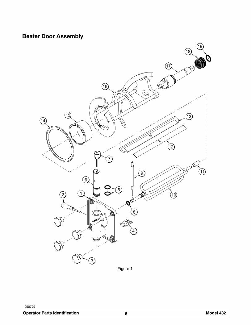
Step 5Return to the freezer with a small amount of cleaningsolution. Brush--clean the rear shell bearing at theback of the freezing cylinder with the black bristlebrush.
Figure 26
Step 6Wipe clean all exterior surfaces of the freezer.
Repeat these steps for the other side of the unit.
21Model 432 Important: Operator Checklist080118
Section 7 Important: Operator Checklist
During Cleaning and Sanitizing:
ALWAYS FOLLOW LOCAL HEALTH CODES.
Cleaning and sanitizing schedules are governedby federal, state, or local regulatory agencies, andmust be followed accordingly. If the unit has a“Standby mode”, it must not be used in lieu ofproper cleaning and sanitizing procedures andfrequencies set forth by the ruling healthauthority. The following check points should bestressed during the cleaning and sanitizingoperations.
CLEANING AND SANITIZING MUST BEPERFORMED DAILY.
Troubleshooting Bacterial Count:
j 1. Thoroughly clean and sanitize machineregularly, including complete disassembly andbrush cleaning.
j 2. Use all brushes supplied for thorough cleaning.The brushes are specially designed to reach allmix passageways.
j 3. Use thewhite bristle brush to clean the mix feedtube, which extends from the hopper down tothe rear of the freezing cylinder.
j 4. Use the black bristle brush to thoroughly cleanthe rear shell bearing located at the rear of thefreezing cylinder. Be sure to have a generousamount of cleaning solution on the brush.
j 5. IF LOCAL HEALTH CODES PERMIT THEUSE OF RERUN, make sure the mix rerun isstored in a sanitized, covered stainless steelcontainer and used the following day. DO NOTprime the machine with rerun. When usingrerun, skim off the foam and discard, then mix
the rerunwith freshmix in a ratio of 50/50duringthe day’s operation.
j 6. On a designated day of theweek, run themix aslow as feasible and discard after closing. Thiswill break the rerun cycle and reduce thepossibility of high bacteria and coliform counts.
j 7. Properly prepare the cleaning and sanitizingsolutions. Read and follow label directionscarefully. Too strong of a solution may damagethe parts and too weak of a solution will not doan adequate job of cleaning or sanitizing.
j 8. Temperature of mix in mix hopper and walk--incooler should be below 40_F. (4.4_C.).
Regular Maintenance Checks:
j 1. Replace scraper blades that are nicked,damaged or worn down. Before installingbeater, be certain the scraper blade is properlyattached.
j 2. Check rear shell bearing for signs of wear(excessive mix leakage in drip pan) and becertain it is properly cleaned.
j 3. Using a screwdriver and cloth towel, keep therear shell bearing and the female square drivesocket clean and free of lubricant and mixdeposits.
j 4. Dispose of o--rings and seals if they are worn,torn, or fit too loosely, and replace with new.
j 5. Follow all lubricating procedures as outlined in“Assembly”.
j 6. Check the condenser(s) for accumulation of dirtand lint. Dirty condensers will reduce theefficiency and capacity of the machine.Condensers should be cleanedmonthly with asoft brush. Never use screwdrivers or othermetal probes to clean between the fins.Note: For machines equipped with an air filter,it will be necessary to vacuum clean the filterson a monthly schedule.

22Important: Operator Checklist Model 432
Winter Storage
If the placeof business is to be closedduring thewintermonths, it is important to protect the freezer byfollowing certain precautions, particularly if thebuilding is to be left unheated and subject to freezingconditions.
Disconnect the freezer from the main power source toprevent possible electrical damage. Your local TaylorDistributor can perform this service for you.
Wrap detachable parts of the freezer such as beater,blades, drive shaft, and freezer door, and place in aprotected dry place. Rubber trim parts and gasketscan be protected by wrapping with moisture--proofpaper. All parts should be thoroughly cleaned of driedmix or lubrication accumulations which attract miceand other vermin.

23Model 432 Troubleshooting Guide
Section 8 Troubleshooting Guide
PROBLEM PROBABLE CAUSE REMEDY PAGEREF.
1. No product beingdispensed.
a. Control switch is in the“OFF” position.
a. Place control switch in the“AUTO” position.
18
b. Improper mixing ofproduct.
b. Carefully follow directionsfor mixing product.
- - -
c. Inadequate mix in hopper. c. Fill hopper with mix. 18
d. Product frozen-up infreezing cylinder.
d. Adjust viscosityadjustment accordingly.
11
e. Unit out on reset. e. Place control switch in the“OFF” position. Press thepush-button switch.Return control switch to“AUTO”.
11
f. Beater assembly isrotating counterclockwise.Control switch is not in“AUTO”.
f. If the beater is rotatingcounterclockwise, call aservice technician tocorrect the rotation.
1
g. Unit unplugged at wallreceptacle.
g. Plug in power cord. - - -
h. Tripped circuit breaker orblown fuse.
h. Reset circuit breaker orreplace fuse.
- - -
2. Unit will not operate in the“AUTO” or “WASH” mode.
a. Unit unplugged at wallreceptacle.
a. Plug in power cord. - - -
b. Tripped circuit breaker orblown fuse.
b. Reset circuit breaker orreplace fuse.
- - -
c. Unit out on reset. c. Place the control switch inthe “OFF” position. Pressthe push-button switch.Return control switch to“AUTO”.
11
3. No compressor operationin the “AUTO” mode.
a. Beater motor is out onoverload.
a. Place control switch in“OFF” position. Press thepush-button switch.Return control switch to“AUTO”.
11
b. Condenser dirty A/C. b. Clean condenser monthly. 21
24Troubleshooting Guide Model 432
PROBLEM PROBABLE CAUSE REMEDY PAGEREF.
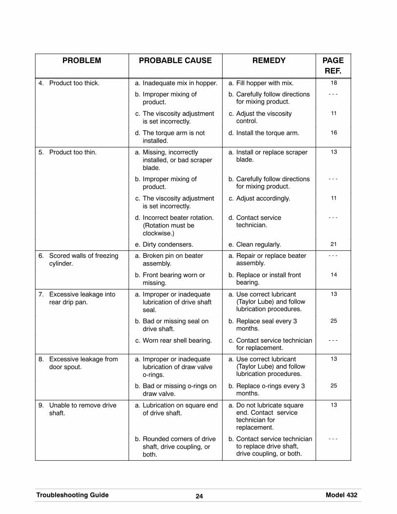
4. Product too thick. a. Inadequate mix in hopper. a. Fill hopper with mix. 18
b. Improper mixing ofproduct.
b. Carefully follow directionsfor mixing product.
- - -
c. The viscosity adjustmentis set incorrectly.
c. Adjust the viscositycontrol.
11
d. The torque arm is notinstalled.
d. Install the torque arm. 16
5. Product too thin. a. Missing, incorrectlyinstalled, or bad scraperblade.
a. Install or replace scraperblade.
13
b. Improper mixing ofproduct.
b. Carefully follow directionsfor mixing product.
- - -
c. The viscosity adjustmentis set incorrectly.
c. Adjust accordingly. 11
d. Incorrect beater rotation.(Rotation must beclockwise.)
d. Contact servicetechnician.
- - -
e. Dirty condensers. e. Clean regularly. 21
6. Scored walls of freezingcylinder.
a. Broken pin on beaterassembly.
a. Repair or replace beaterassembly.
- - -
b. Front bearing worn ormissing.
b. Replace or install frontbearing.
14
7. Excessive leakage intorear drip pan.
a. Improper or inadequatelubrication of drive shaftseal.
a. Use correct lubricant(Taylor Lube) and followlubrication procedures.
13
b. Bad or missing seal ondrive shaft.
b. Replace seal every 3months.
25
c. Worn rear shell bearing. c. Contact service technicianfor replacement.
- - -
8. Excessive leakage fromdoor spout.
a. Improper or inadequatelubrication of draw valveo-rings.
a. Use correct lubricant(Taylor Lube) and followlubrication procedures.
13
b. Bad or missing o-rings ondraw valve.
b. Replace o-rings every 3months.
25
9. Unable to remove driveshaft.
a. Lubrication on square endof drive shaft.
a. Do not lubricate squareend. Contact servicetechnician forreplacement.
13
b. Rounded corners of driveshaft, drive coupling, orboth.
b. Contact service technicianto replace drive shaft,drive coupling, or both.
- - -

25Model 432 Parts Replacement Schedule
Section 9 Parts Replacement Schedule
PART DESCRIPTION EVERY 3MONTHS
EVERY 4MONTHS
EVERY 6MONTHS
ANNUALLY QUANTITIESTO BE
REPLACED
Drive Shaft Seal X 2
Drive Shaft O-Ring X 2
Scraper Blade X 2
Freezer Door Gasket X 2
Front Bearing X 2
Guide Bearing X 2
Torque Rotor O-Ring X 2
Draw Valve O-Rings X 4
Black Bristle Brush - 1” x 2” Inspect &Replace ifNecessary
Maximum 1
White Bristle Brush -1-1/2” x 2”
Inspect &Replace ifNecessary
Maximum 1
White Bristle Brush - 3” x 7” Inspect &Replace ifNecessary
Maximum 1

Section 10 Parts List
+ Available Separately
26Parts List Model 432080619
DES
CR
IPTI
ON
PAR
TN
UM
BER
QTY
.W
AR
R.
CLA
SSR
EMA
RK
SPARTS
UPDATE
432
STA
ND
AR
D(0
4322
7F00
020
8-23
0V60
HZ
1PH
)A
/C-B
RIS
TOL-
R40
4A
AC
CU
MU
LATO
R-C
OP
PE
R2"
DIA
10"L
G04
7062
110
3
AR
M-T
OR
QU
E-4
3205
2450
210
3B
ALL
AS
T-FL
UO
RE
SC
EN
T06
5764
-27
110
3+S
OC
KE
T-FL
UO
RE
SC
EN
TLA
MP
0454
431
103
+CLI
P-F
LUO
RE
SC
EN
TLA
MP
0454
441
103
+BU
LB-L
IGH
T-FL
UO
RE
SC
EN
T-U
SH
AP
E04
5445
100
0G
E#F
27B
XS
PX
41+B
RA
CK
ET-
LIG
HT
0522
431
103
+PLA
TE-S
TOP
-LIG
HT
0522
441
103
BE
AR
ING
-FR
ON
T01
3116
200
0B
EA
RIN
G-G
UID
E01
4496
200
0B
EA
RIN
G-R
EA
RS
HE
LL*P
LAS
TIC
*03
2511
200
0+G
UID
E-D
RIP
SE
AL
0289
922
000
+NU
T-B
RA
SS
BE
AR
ING
0289
912
000
+WA
SH
ER
-BE
AR
ING
LOC
K01
2864
200
0B
EA
TER
A.-4
QT-
1P
IN-S
UP
PO
RT
X49
490
210
3S
/NK
8068
046
&U
P-R
EP
LAC
ES
X51
800
+BLA
DE
-SC
RA
PE
R-P
LAS
TIC
9-13
/16L
0462
372
000
+CLI
P-S
CR
AP
ER
BLA
DE
8.75
INC
H04
6238
210
3B
ELT
-V-4
L510
(LO
NG
)01
5192
100
0R
IGH
T-F
AC
ING
FRO
NT
OF
MA
CH
INE
BE
LT-V
-4L3
20(S
HO
RT)
0238
621
000
LEFT
-FA
CIN
GFR
ON
TO
FM
AC
HIN
EB
LOC
K-T
ER
MIN
AL
2P.2
5S
PA
DE
0516
441
103
BLO
CK
-TE
RM
INA
L-5
PO
LE02
4329
210
3B
LOC
K-T
ER
MIN
AL-
2P
OLE
0394
221
103
BLO
CK
-TE
RM
INA
L-P
LUG
7P.2
SIP
0403
22-0
032
103
BLO
CK
-TE
RM
INA
L-P
LUG
8P.2
SIP
0403
22-0
042
103
BR
US
H-R
EA
RB
RG
1IN
.DX
2IN
.LG
X14
0130
711
000
BR
US
H-D
OU
BLE
EN
DE
D-P
UM
P&
FEE
DT
0130
721
000
BR
US
H-D
RA
WV
ALV
E1-
1/2"
OD
X3"
0147
531
000
BR
US
H-M
IXP
UM
PB
OD
Y-3
"X7"
WH
ITE
0233
161
000
BU
SH
ING
-SN
AP
15/1
6ID
X1-
3/32
0233
962
103

27
+ Available Separately
Model 432 Parts List
DES
CR
IPTI
ON
PARTS
UPDATE
REM
AR
KS
WA
RR
.C
LASS
QTY
.PA
RT
NU
MB
ERB
US
HIN
G-S
NA
P11
/16
IDX
7/8O
D01
0548
110
3C
OM
PR
ES
SO
RL6
1B56
2BB
CB
(BR
ISTO
L)04
8727
-27E
151
220
8-23
0/60
/1+C
AP
AC
ITO
R-R
UN
30U
F/37
0V03
8487
110
320
8-23
0/60
/1+C
AP
AC
ITO
R-S
TAR
T-16
1-19
3UF/
250V
0317
901
103
208-
230/
60/1
+RE
LAY
-STA
RT-
CO
MP
RE
SS
OR
0470
671
103
208-
230/
60/1
CO
ND
EN
SE
R-A
C-1
5LX
14H
X2.
59T-
3RO
W04
6558
110
3C
OU
PLI
NG
-3/8
FSX
1/4F
S03
1791
110
3LI
NE
A.-D
ISC
HA
RG
EC
OV
ER
A.-H
OP
PE
R*4
32*
X52
452
210
3D
EC
AL-
INS
T-C
LNH
PR
0190
291
000
DE
CA
L-TR
OU
BLE
SH
OO
T03
8374
100
0D
EC
AL-
DE
C-T
AY
LOR
DO
ME
D05
3761
100
0D
EC
AL-
STA
TIC
CLI
NG
432
SE
T/5
0567
801
000
DE
CA
L-S
WIT
CH
CO
NTR
OL-
OFF
/ON
0429
411
000
DIA
GR
AM
-WIR
ING
*432
*05
2145
-27
100
020
8-23
0V60
HZ
1PH
DO
OR
A.-P
AR
TIA
L*3
40-3
50-4
50X
3924
82
103
+BU
STE
R-IC
E04
7735
210
3+H
AN
DLE
A.-D
RA
W-S
LUS
H-B
LAC
KX
4738
42
103
+PIN
A.-V
ALV
EH
AN
DLE
X25
929
210
3+V
ALV
E-D
RA
W*S
LUS
H*I
CE
BU
STE
0477
342
103
+O-R
ING
-1"O
DX
.139
W03
2504
400
0D
RY
ER
-FIL
TER
3/8
X3/
8S
OLD
ER
0491
541
000
LIQ
UID
LIN
ED
RY
/SO
LFA
STE
NE
R-C
LIP
10-3
2U
-TY
PE
CR
306
4719
410
3FI
LTE
R-C
OR
CO
M2V
R1
0325
672
103
GA
SK
ET-
BA
SE
PA
N*4
32*
0523
771
000
+SC
RE
W-1
0X7/
16U
NS
LTD
HW
H06
6234
1100
0B
AS
EP
AN
GA
SK
ET
GA
SK
ET-
DO
OR
5.10
9"ID
X5.
630O
D01
4030
200
0G
AS
KE
T-FR
ON
TP
AN
EL
0490
312
000
GE
AR
A.*R
ED
UC
ER
4.92
:1S
ER
VIC
E01
5985
-SE
R2
212
GU
IDE
A.-D
RIP
PA
N*4
32*
X52
352
210
3K
ITA
.-TU
NE
UP
*SLU
SH
*X
3996
92
000
BE
AR
ING
-FR
ON
T01
3116
200
0B
EA
RIN
G-G
UID
E01
4496
200
0G
AS
KE
T-D
OO
R5.
109"
IDX
5.63
001
4030
200
0

+ Available Separately
28Parts List Model 432
DES
CR
IPTI
ON
PARTS
UPDATE
REM
AR
KS
WA
RR
.C
LASS
QTY
.PA
RT
NU
MB
ERO
-RIN
G-.2
91ID
X.0
80W
0185
502
000
O-R
ING
-7/8
OD
X.1
39W
0253
072
000
O-R
ING
-1"O
DX
.139
W03
2504
400
0S
EA
L-D
RIV
ES
HA
FT03
2560
200
0TO
OL-
O-R
ING
RE
MO
VA
L-FR
EE
ZER
0482
60-W
HT
200
0LA
BE
L-C
AU
TIO
N-G
RD
-PE
RM
-EN
G/S
P03
2164
100
0LA
BE
L-W
AR
N-C
OV
ER
0514
336
000
LAB
EL-
SW
ITC
HW
AS
H/O
FF/A
UTO
0145
022
000
LIG
HT-
AM
BE
R-R
EC
T-12
VD
C-A
DD
MIX
0524
86-0
22
103
LIG
HT-
AM
BE
R-R
EC
T-12
VD
C-M
IXO
UT
0524
87-0
22
103
LUB
RIC
AN
T-TA
YLO
R4
OZ.
0475
181
000
MA
N-O
PE
R43
205
3081
-M1
000
MO
TOR
-1/4
HP
0144
77-2
72
212
MO
TOR
-FA
N50
WA
TT02
9770
-27
110
3+F
AN
-5B
LAD
E12
"PU
SH
22D
EG
CC
W04
9009
110
3N
UT-
STU
D*3
45-3
46-3
49-3
55*
0436
668
103
PA
IL-M
IX10
QT.
0131
631
000
PA
N-D
RIP
17-1
/4"L
ON
G02
7504
210
3P
AN
EL
A.-U
PP
ER
FRO
NT
*432
X66
410
S/N
K80
6804
6&
UP
-RE
PLA
CE
S05
2360
PA
NE
L-FR
ON
T*4
32*U
PP
ER
0523
601
103
S/N
K80
6804
5&
PR
IOR
PA
NE
L-FR
ON
T*4
32*L
OW
ER
0523
611
103
PA
NE
L-R
EA
R05
2363
110
3P
AN
EL-
SID
E*4
32*R
IGH
T*LO
UV
ER
0525
271
103
PA
NE
L-S
IDE
-LE
FT*4
32*
0663
961
103
S/N
K80
4197
3&
UP
RE
PLA
CLE
S05
2362
PC
BA
.-CO
NTR
OL
*432
*X
5242
0-S
ER
221
2C
ON
TRO
LC
HIP
-SO
FTW
AR
E43
2TO
RQ
UE
X40
879
210
3P
CB
A.-C
ON
TRO
L-TO
RQ
UE
X53
507-
SE
R2
212
PLA
TEA
.-DE
C*4
32*L
IGH
TED
X52
357
110
3+L
EN
S-D
EC
PLA
TE05
2359
110
3P
LUG
-HO
LE7/
8D
IA.B
LAC
K01
0077
100
0P
RO
BE
A.-M
IXLO
WX
5237
52
103
MIX
LOW
PR
OB
EA
.-MIX
OU
T-S
QU
AR
EH
OLE
X41
348
210
3M
IXO
UT
PU
LLE
Y-A
K27
-1/2
0161
902
103

29
+ Available Separately
Model 432 Parts List
DES
CR
IPTI
ON
PARTS
UPDATE
REM
AR
KS
WA
RR
.C
LASS
QTY
.PA
RT
NU
MB
ERP
ULL
EY
-AK
4905
1394
210
3R
ELA
Y-3
PO
LE-2
0A-2
08/2
4050
/60
0127
25-3
31
103
CO
MP
RE
SS
OR
CO
NTA
CTO
R(P
RIM
AR
Y)
RE
LAY
-SP
DT-
30A
-240
V03
2607
-27
210
3B
EA
TER
MO
TOR
RE
LAY
-DP
DT-
20A
-230
V02
6581
-27
410
3LA
TCH
ING
/CO
MP
RE
SS
OR
RE
LAY
SA
NIT
IZE
RK
AY
-512
5P
AC
KE
TS04
1082
100
0S
CR
EW
-10-
32X
3/8
UN
SL
HW
H03
9381
1900
0S
CR
EW
-10X
7/16
UN
SL
TDH
WH
0662
3411
000
SC
RE
W-6
-32X
3/8
SLT
DB
IND
ER
0022
019
000
SC
RE
W-1
0X3/
8S
LOTT
ED
HE
XW
SH
R01
5582
600
0S
CR
EW
-10-
32X
1/2
SLT
DTR
US
S03
7734
1900
0S
CR
EW
-10X
3/8
SLO
TTE
DH
EX
WS
HR
0155
822
000
SH
AFT
-BE
ATE
R*3
41-2
RFB
*03
5418
210
3+O
-RIN
G-7
/8O
DX
.139
W02
5307
200
0+S
EA
L-D
RIV
ES
HA
FT03
2560
200
0S
HE
LF-D
RIP
TRA
Y*3
82-3
84*
0520
651
103
SH
ELL
A.-I
NS
ULA
TED
*432
*X
5480
1-S
ER
151
2+S
TUD
-NO
SE
CO
NE
-5/1
6-18
X5/
16-1
801
3496
810
3+W
AS
HE
R-F
RE
EZE
RS
TUD
*RD
30*
0490
328
103
SH
IELD
-SP
LAS
H*3
80/1
*04
6851
110
3S
HR
OU
D-F
AN
0390
231
103
SW
ITC
HA
.-TO
RQ
UE
*432
*X
5223
32
103
+AR
M-T
OR
QU
E-C
ON
TRO
L05
2232
210
3B
US
HIN
GA
.-TO
RQ
UE
X50
399-
SE
R2
103
SP
RIN
G-T
OR
QU
E*R
ED
*02
0232
210
3+B
US
HIN
G-A
RM
-TO
RQ
UE
0497
372
103
+BU
SH
ING
-PIV
OT-
TOR
QU
EA
RM
0497
392
103
BR
AC
KE
T-A
DJ.
-TO
RQ
UE
0522
272
103
RO
D-S
WIT
CH
0522
312
103
SP
RIN
G-C
OM
P.
0254
522
103
E-R
ING
5/16
0164
222
000
SW
ITC
H-L
EV
ER
-SP
DT-
1A-1
25V
0620
222
103
SW
ITC
H-L
EV
ER
-SP
DT-
.1A
-125
V07
4821
210
3S
WIT
CH
-PU
SH
BU
TTO
N-S
PS
T01
6530
210
3

+ Available Separately
30Parts List Model 432
DES
CR
IPTI
ON
PARTS
UPDATE
REM
AR
KS
WA
RR
.C
LASS
QTY
.PA
RT
NU
MB
ERS
WIT
CH
-PR
ES
SU
RE
440
PS
I-SO
LDE
R04
8230
110
3S
WIT
CH
-TO
GG
LE-S
PS
T3/
4HP
/250
V01
2626
110
3LI
GH
TS
WIT
CH
-TO
GG
LE-3
PD
T01
7184
210
3W
AS
H/O
FF/A
UTO
TOR
QU
EA
.*43
0*X
5038
22
000
+O-R
ING
-.291
IDX
.080
W01
8550
200
0TR
AY
A.-D
RIP
*383
/384
/432
X46
848
110
3TU
BE
-CA
PIL
LAR
Y-9
FEE
T02
0059
210
3+T
EE
-1/4
SC
OP
PE
R00
3949
210
3TU
BE
-FE
ED
-NO
NR
EV
ER
S3/
8H
OLE
0151
76-9
210
3V
ALV
E-A
CC
ES
S-1
/4M
FLX
3/8O
DS
DR
0535
652
103
VA
LVE
-EP
R1/
4S02
2665
210
3V
ALV
E-E
XP
-AU
TO-1
/4S
X1/
4FP
T04
6365
210
3+B
OO
T-V
ALV
E-E
XP
AN
SIO
N05
0900
200
0V
ALV
E-S
OLE
NO
ID04
3449
-27
210
3LI
QU
IDLI
NE
VA
LVE
-SO
LEN
OID
0449
82-2
72
103
SU
CTI
ON
LIN
E
DES
CR
IPTI
ON
PAR
TN
UM
BER
QTY
.W
AR
R.
CLA
SSR
EMA
RK
SPARTS
UPDATE
3PH
ASE
(043
233F
000
208-
230V
60H
Z3P
H)
A/C
-BR
ISTO
L-R
404A
BLO
CK
-TE
RM
INA
L3P
L1,L
2,L
0394
231
103
CO
MP
RE
SS
OR
L63B
562D
BLB
0487
27-3
3E1
512
DIA
GR
AM
-WIR
ING
*432
*05
2145
-33
100
0
Model 432052145--275/08

Model 432052145--335/08
Model 432052145--404/08