Embed Size (px)
Citation preview

Model 1073 Tower Lightning Protection User's Manual
All Weather Inc. • 1165 National Drive • Sacramento, CA 95834 • USA • www.allweatherinc.com

1073 Tower Lightning Protection User's Manual
Page i
CONTENTS INTRODUCTION ..........................................................................................................................1
SPECIFICATIONS........................................................................................................................1
INSTALLATION ............................................................................................................................2
WARRANTY .................................................................................................................................3
DRAWINGS AND PARTS LIST....................................................................................................3

1073 Tower Lightning Protection User's Manual
Page 1
INTRODUCTION Meteorological equipment is constantly exposed to the worst elements of nature, including lightning. Typically, weather stations are installed on the tops of hills, buildings, and tall towers for the best exposure possible in order to achieve maximum quality of data. Such installations are prime targets for lightning strikes and are often hit by lightning more than once a month.
The failure of many meteorological stations using sophisticated electronic data systems can be directly attributed to poor or no lightning protection.
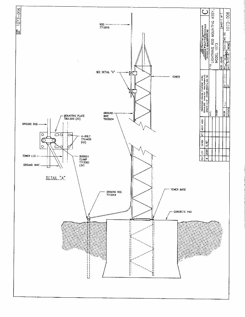
In answer to the problem of lightning strikes, All Weather Inc. provides tower lightning protection packages Models 1073, 1073-B, 1073-C, and 1073-D. These packages provide lightning and grounding rods, heavy copper wire down lead, and mounting hardware. When installed onto a tower and properly grounded, the tower lightning protection package provides a direct ground path from the top of the tower, conducting any electrical charges due to lightning or to any other form of static buildup directly to earth ground.
Models 1073 and 1073-C provide two mounting plates for attaching the lightning rod to one of the tower legs at the top or within 2 feet of the top of the tower. Model 1073-B uses eight four foot booms for mounting the lightning rod to one side of the tower, approximately 4 feet from The top. Model 1073-D is used with a special top plate on towers for AWOS systems.
Models 1073, 1073-C, and 1073-D are used on towers where there are no sensors mounted directly at the top of the tower or with sensors whose operation would not be obstructed by the proximity of the lightning rod. Model 1073-B is used on towers with widths of 18 inches or greater where the sensor is to be mounted at the top of the tower and sensors would be obstructed by the lightning rod.
Model 1073-C is primarily used on the 10-foot tripod tower and has a slight bend in the lightning rod to clear sensors such as the Model 2100.
Model 1073-D is used for special applications such as airport systems (AWOS). The base ground rod has a diameter of 3/4 inches and a length of 10 feet. The standard size ground rod provided by All Weather Inc. has a diameter of 5/8 inches and a length of 8 feet. Refer to drawing 1073-D06.
SPECIFICATIONS
Lightning rod 1073 and 1073-C 5/8" x 8 feet, copper plated, (16 mm x 2 mm) 1073-D 5/8" x 5 feet, copper plated (16 mm x 1.5 m) Ground rod 1073 and 1073-C 8/8" x 8 feet. copper plated (16 mm x 2 mm) 1073-D 3/4" x 10 feet, copper plated (19 mm x 3 mm) Down lead 2-0 copper wire, standard, bare or insulated Mounting Plates or booms with u-bolts

User's Manual 1073 Tower Lightning Protection
Page 2
INSTALLATION This instrument is thoroughly inspected at the factory and is ready for installation. Please refer to the return authorization card included in the packing box if damage has occurred. Also, notify All Weather Inc.
Specific installation may vary slightly depending upon the tower selected and upon the location of instruments at the top of the tower.
1. The installation should proceed from the ground upward starting with the ground rod. The
ground rod should be driven into soil at or as close to the tower base as possible. If the soil is rocky, the site may require blasting in order to set guy wire anchors, the tower base and the ground rod. Always use the full length of the ground rod. Never cut the rod or drive it only part way in.
2. Leave three to four inches of rod exposed above the soil. Attach the 2-0 copper wire to the
ground rod using the clamp provided. 3. Route the copper cable up one leg of the tower. Firmly wrap the cable to the tower leg every
eight to four feet using the wrap-lock kit provided. Refer to the drawing at the end of this manual for instructions in the use of the wrap-lock kit.
4. Do not make any sharp bends or angles in the cable when installing it onto the tower. Leave
some slack in the cable at the lightning rod end. 5. Install the lightning rod assembly for Models 1073 and 1073-C. First mount the brackets
onto the tower legs, then loosen the clamps on the brackets and slide the copper rod through both clamps. Tighten the top plate clamp. Feed the copper cable into the lower plate clamp along with the copper rod. Fasten the lower plate clamp.
6. The final installation should look similar to that shown in the assembly drawing in this
manual. The major portion of the lightning rod should extend above the top of the tower and the tallest instrument. If necessary, carefully loosen the clamps and adjust the rod as needed. It may be helpful to place a small clamp onto the rod above the top plate as a precaution against dropping the rod when loosening the clamps. The small clamp is a bolt-on oval shaped clamp that will rest against the large clamps if the rod slips during installation.
7. The Model 1073-B is installed by first mounting the booms, then mounting the lightning rod.
The booms are mounted onto the tower legs with long bolts and clamping brackets. Refer to the drawing in this manual. The clamping brackets press the boom against the tower legs.
8. The booms can be loosely fastened to allow installation of the lightning rod onto the ends of
the booms, then the entire assembly moved out away from the tower face. 9. The lightning rod is held in place with two clamps, one above the top boom and one below
the bottom boom. The lower clamp also attaches the copper cable to the rod. The rod is installed from the top using the upper clamp as a safety stop during installation.

1073 Tower Lightning Protection User's Manual
Page 3
10. The Model 1073-D lightning rod is supported by a 3' x 5/8" galvanized rod attached to the
lightning rod and tower with four clamps. 11. Check all bolts to ensure complete and safe installation of the plates and booms. 12. The fittings should be checked whenever the tower is serviced. Checks should also be made
for corrosion and damage due to weather and lightning.
WARRANTY Unless specified otherwise, All Weather Inc. (the Company) warrants its products to be free from defects in material and workmanship under normal use and service for one year from date of shipment, subject to the following conditions:
(a) The obligation of the Company under this warranty is limited to repairing or replacing items or parts which have been returned to the Company and which upon examination are disclosed, to the Company’s satisfaction, to have been defective in material or workmanship at time of manufacture.
(b) The claimant shall pay the cost of shipping any part or instrument to the Company. If the Company determines the part to be defective in material or workmanship, the Company shall prepay the cost of shipping the repaired instrument to the claimant. Under no circumstances will the Company reimburse claimant for cost incurred in removing and/or reinstalling replacement parts.
(c) This warranty shall not apply to any Company products which have been subjected to misuse, negligence or accident.
(d) This warranty and the Company’s obligation thereunder is in lieu of all other warranties, express or implied, including warranties of merchantability and fitness for a particular purpose, consequential damages and all other obligations or liabilities.
No other person or organization is authorized to give any other warranty or to assume any
additional obligation on the Company’s behalf, unless made in writing and signed by an authorized officer of the Company.
DRAWINGS AND PARTS LIST The following pages include assembly drawings and parts list for this instrument. Please note that the parts lists are arranged in assembly/sub-assembly form. Each sub-assembly is on its own page. Sub-assemblies and parts are listed in the smallest economical size available from All Weather Inc.


All Weather Inc. 1165 National Drive Sacramento, CA 95818 Fax: 916.928.1165 1073-001 Phone: 916.928.1000 ECN 4060 Toll Free: 800.824.5873 March, 1992