Embed Size (px)
Citation preview

LD250-02232018
BOLTEK CORPORATION Lightning Detection
LD-250 Lightning Detector Installation/Operators Guide
SEE DISCLAIMER ON REVERSE

B O L T E K L I G H T N I N G D E T E C T I O N
LD-250 Lightning Detector
Disclaimer
LD-250 lightning data is only approximate and should not be used for safety applications. Strike and storm locations indicated and alarm statuses may be erroneous and should not be used to safeguard personnel,
equipment or data.
Neither Boltek Corporation nor its affiliates shall be liable to the purchaser of this product or third parties for damages, losses, costs, or expenses incurred by purchaser or third parties as a result of use, misuse,
accident, or abuse.
Notwithstanding the above Boltek Corp’s liability shall not exceed the purchase price of the equipment.
THIS EQUIPMENT IS NOT TO BE USED FOR SAFETY PURPOSES
2000-2018 Boltek Corporation
4 Stonebridge Drive Unit 2 Port Colborne, ON.
L3K5V5 Canada
Email: [email protected] Web: www.boltek.com
Phone (905) 734-8045 • Fax (905) 734-9049

FCC Compliance Statement For United States Users
This equipment is tested and found to comply with the limits for a Class B digital device, pursuant to Part 15 of the FCC Rules. These limits are designed to provide reasonable protection against harmful interference in a residential installation. This equipment generates, uses, and can radiate radio frequency energy and, if not installed and used in accordance with the instructions, may cause harmful interference to radio or television reception. However, there is no guarantee that interference will not occur in a particular installation. If this equipment does cause interference to radio and television reception, which can be determined by turning the equipment on and off, the user is encouraged to try to correct the interference by one or more of the following measures.
• Reorient or relocate the receiving antenna. • Increase the separation between the equipment and the receiver. • Connect the equipment into an outlet on a circuit different from that to which the receiver is connected. • Consult the dealer or an experienced radio/TV technician for help.
WARNING
The connection of a non-shielded equipment interface cable to this equipment will invalidate the FCC Certification of this device and may cause interference levels which exceed the limits established by the FCC for this equipment. It is the responsibility of the user to use a shielded interface cable with this device. If this equipment has more than one interface connector, do not leave cables connected to unused interfaces. Changes or modifications not expressly approved by the manufacturer could void the user’s authority to operate the equipment.
For Canadian Users This Class B digital apparatus meets all requirements of the Canadian Interference-Causing Equipment Regulations. Cet appareil numérique de la class B respecte toutes les exigences du Règlement sur le materiel brouilleur du Canada.
WARNING
DO NOT ATTEMPT TO OPERATE THE LD-250 OR THE DISPLAY SOFTWARE WHILE DRIVING YOUR VEHICLE


Table of Contents
Installation ........................................................................................... 4 Quick Start .......................................................................................... 5 Installing the Antenna ......................................................................... 6 Installing the USB Adapter Cable .................................................... 12
Operation ........................................................................................... 14 Mobile Operation.............................................................................. 14 GPS/Compass Connection ................................................................ 14 Front Panel Controls ........................................................................ 15 Noise ................................................................................................. 16 Receiver Range ................................................................................. 16
RS232 Commands and Messages .................................................... 17 Commands .................................................................................. 17 RS232 Messages ..................................................................... 18
Making an Antenna Cable ............................................................... 19


I N S T A L L A T I O N
4
Installation he LD-250 Lightning Detector puts a live lightning map on your laptop or desktop computer. The LD-250 is suitable for use in mobile, portable or fixed installations. With two antennas you can move the unit between a fixed installation and a portable installation. When used mobile the LD-250 requires a GPS connected to
the GPS/Compass NMEA port on the rear of the unit. Your LD-250 package should contain: 1 LD-250 lightning detector 1 ANT-2 lightning sensor (pre-assembled with mast and mounting bracket) 3 x Stainless Steel Clamps (Range 1-13/16" to 2-3/4" / 46 to 70mm) 3 x Stainless Steel Clamps (Range 3-1/16" to 4" / 78 to 102 mm) 1 antenna cable (Cat6 Direct Burial),
standard length 50 feet (15 meters) 1 AC wall adapter,
120VAC to 12VDC for North America Or 220VAC to 12VDC Universal Adapter
1 12V DC automotive/accessory power cable 1 GPS/Compass connector to pigtail cable 1 DB-9 male to DB-9 female RS232 cable 1 USB to RS232 adapter cable 2 Velcro strips for mobile mounting 4 rubber feet for desktop mounting 1 USB Flash Drive containing Windows display software, drivers, and manuals 1 user manual (this is it) Unpack your LD-250 and make sure all the parts are included.
Chapter
1 T

I N S T A L L A T I O N
5
Quick Start 1) Connect the USB-RS232 cable from your computer’s USB port (or the DB-9 cable from your computer’s serial COM port) to the RS232 connector on the back of the LD-250. 2) Plug in the AC power adapter into the power connector of the LD-250 and into an AC outlet. Turn on the LD-250. It should beep and illuminate the indicator lights for 2 seconds. 3) If using the USB-RS232 cable, you may need to install the drivers from the mini CDROM disc first if Windows doesn’t install them automatically. 4) Install the Lightning Display software provided on the Boltek USB flash drive, then run application after installation is completed and select LD-250 and the appropriate COM port under the hardware configuration options menu. You may need to check the Windows Device manager to see the virtual COM port assigned to the USB-RS232 cable. 5) Remove the three screws on the ANT-2 and remove it from the mast then connect the antenna cable to both the LD-250 and the ANT-2. Hold the ANT-2 a few feet from a computer monitor or television (a laptop computer display may not produce enough noise). The LD-250 should detect the radio frequency noise from the monitor as a constant stream of noises and/or strikes. By moving the ANT-2 you should be able to find a position that produces strikes. Strike counts and location markers should appear on the display. Rotating the antenna should change the strike direction. 6) Mount the antenna away from televisions, computer monitors, motors, fans and other sources of electrical noise.
I N S T A L L A T I O N
6
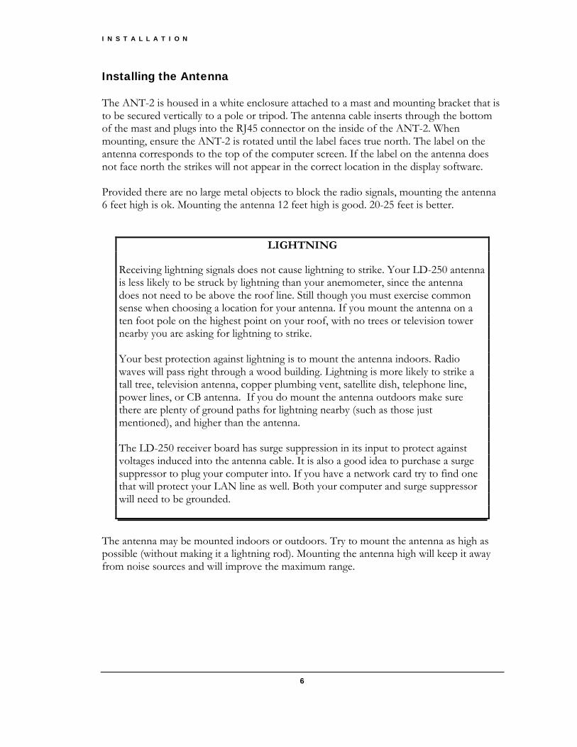
Installing the Antenna The ANT-2 is housed in a white enclosure attached to a mast and mounting bracket that is to be secured vertically to a pole or tripod. The antenna cable inserts through the bottom of the mast and plugs into the RJ45 connector on the inside of the ANT-2. When mounting, ensure the ANT-2 is rotated until the label faces true north. The label on the antenna corresponds to the top of the computer screen. If the label on the antenna does not face north the strikes will not appear in the correct location in the display software. Provided there are no large metal objects to block the radio signals, mounting the antenna 6 feet high is ok. Mounting the antenna 12 feet high is good. 20-25 feet is better.
LIGHTNING Receiving lightning signals does not cause lightning to strike. Your LD-250 antenna is less likely to be struck by lightning than your anemometer, since the antenna does not need to be above the roof line. Still though you must exercise common sense when choosing a location for your antenna. If you mount the antenna on a ten foot pole on the highest point on your roof, with no trees or television tower nearby you are asking for lightning to strike. Your best protection against lightning is to mount the antenna indoors. Radio waves will pass right through a wood building. Lightning is more likely to strike a tall tree, television antenna, copper plumbing vent, satellite dish, telephone line, power lines, or CB antenna. If you do mount the antenna outdoors make sure there are plenty of ground paths for lightning nearby (such as those just mentioned), and higher than the antenna. The LD-250 receiver board has surge suppression in its input to protect against voltages induced into the antenna cable. It is also a good idea to purchase a surge suppressor to plug your computer into. If you have a network card try to find one that will protect your LAN line as well. Both your computer and surge suppressor will need to be grounded.
The antenna may be mounted indoors or outdoors. Try to mount the antenna as high as possible (without making it a lightning rod). Mounting the antenna high will keep it away from noise sources and will improve the maximum range.

I N S T A L L A T I O N
7
In a wood framed house, the second floor or attic is often a good location for the antenna. This places the antenna above the most common sources of interference: televisions, lights and appliances, yet leaves it in a good location to receive lightning signals. Mount the antenna to the drywall or attic rafter away from screws, nails, electrical wiring, and other metal objects. If your house has aluminum siding (vinyl siding is ok), foil-lined insulation, or any other metal coating, you might have problems receiving with the antenna indoors, as the metal may shield radio waves from the antenna. DO NOT MOUNT THE ANTENNA SO AS TO ATTRACT LIGHTNING. The antenna does not need to be the highest object in the area to receive lightning signals. DO NOT LOCATE THE ANTENNA NEAR AN OBJECT WHICH IS LIKELY TO BE STRUCK BY LIGHTNING. Objects such as television antennas, CB antennas, power lines, phone lines and tall trees are natural targets for lightning. Keep the antenna and cable away from anything which might be struck by lightning. Lightning can jump from one object to another in its search for ground.
LD-250 Connection Diagram

I N S T A L L A T I O N
8
The antenna can be mounted with the supplied clamps. Two different sizes of clamps are provided to allow for various diameter sizes of the pole or tripod the antenna is being mounted to.

I N S T A L L A T I O N
9
Attaching Cable to ANT-2 First remove the three screws and very carefully remove the white housing from the bottom cover plate.
Insert the cable into the bottom of the mast and push up until the cable comes all the way through to the other end.

I N S T A L L A T I O N
10
Insert the cable connector into the RJ45 connector on the ANT-2.
Re-attach the antenna to the bottom cover plate with the three screws and affix mounting bracket to pole or tripod with three clamps. Fasten the cable to the wall or support about 6-12" below the antenna. Leave a bit of slack in the cable near the antenna so that there is no strain on the connector from the wire. If you find the 50' antenna cable provided is not long enough you may purchase a custom length of cable up to 200' to go from the LD-250 to the ANT-2. You may also purchase a replacement cable at any computer store selling network hardware. Any Category 5 or 6 cable up to 200 feet will work. See Appendix C for information on making your own antenna cable.

I N S T A L L A T I O N
11
ANT-2 shown with pole mount installation
ANT-2 shown with tripod installation
I N S T A L L A T I O N
12
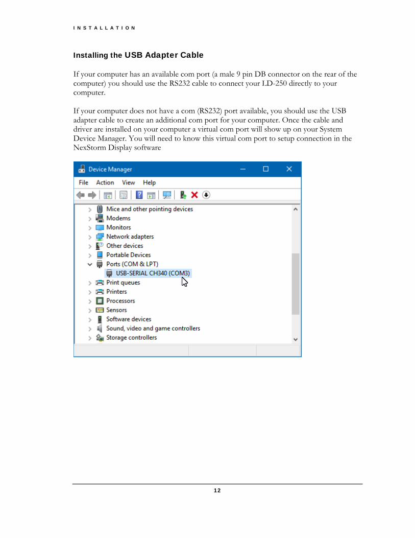
Installing the USB Adapter Cable If your computer has an available com port (a male 9 pin DB connector on the rear of the computer) you should use the RS232 cable to connect your LD-250 directly to your computer. If your computer does not have a com (RS232) port available, you should use the USB adapter cable to create an additional com port for your computer. Once the cable and driver are installed on your computer a virtual com port will show up on your System Device Manager. You will need to know this virtual com port to setup connection in the NexStorm Display software

I N S T A L L A T I O N
13
Installing the USB Adapter Cable: With your computer turned on plug the USB adapter cable into a spare USB port on your computer or hub. USB devices may be plugged and unplugged with the power on. Windows will detect the new device and install the drivers automatically. If the computer does not have internet access, Place the USB Drivers CDROM in your computer disk drive. Open Windows File Explorer and copy the setup.exe file from the CDROM to your local hard drive then run the setup executable.
If the Windows Security prompt appears, click accept to continue driver installation. Once the drivers have finished installing the following window will appear.
Click OK button to complete the installation procedure, then plug in the USB-RS232 adapter. Refer back to your Windows Device Manager to view the virtual com port assigned to the adapter.

O P E R A T I O N
14
Operation
Mobile Operation
Normally the front of the LD-250 antenna needs to face north. In a mobile situation the orientation of the antenna would be constantly changing as the vehicle turns. The LD-250 has the ability to correct for this by using heading data from a GPS or marine compass. As long as you are moving forward your GPS will know which direction you are traveling and, at least for an automobile, which direction your vehicle is facing. The GPS looks for change in location to calculate your heading. Since a boat can change directions without necessarily changing position (rotating on its anchor for example) a marine compass is recommended for marine applications. GPS/Compass Connection The LD-250 has a NMEA port on the read panel to connect to a GPS or compass for mobile operation. A GPS or marine compass connection is required for mobile use since the LD-250 needs to know which direction the antenna is pointed.
GPS /COMPASS WIRE CONNECTIONS BLUE NMEA data + YELLOW no connection GREEN NMEA data in – RED +12V to power GPS or compass BLACK Ground for GPS or compass WHITE NMEA data out (not implemented)
If your GPS does not provide a NMEA Data – connection you should connect the LD-250’s NMEA Data – (green wire) to ground (black wire).
Chapter
2

O P E R A T I O N
15
Front Panel Controls
Main Power Button The main power button disconnects 12V power from the LD-250, the antenna, and the GPS connector on the rear of the LD-250. Main Power Indicator The power indicator illuminates to indicate 12V power is present at the LD-250. If the indicator does not light when the unit is turned on check your 12V power source. Strike Indicator The Strike Indicator emits a short flash when a lightning strike is detected. If the Strike Tone Button is pressed the detector also emits a short beep. Noise Indicator The Strike Indicator emits a short flash when a noise signal is detected. If the Strike Tone Button is pressed and Noise Beeps have been turned on in software the detector will also emits a short beep. Strike/Noise Switch When pushed in, the internal beeper will emit a short beep when a strike or noise signal is detected. When pushed out, no sound will emit from the internal beeper. Close/Severe Alarm Switch When pushed in, the internal beeper will emit a long beep when a close strike or severe strike rate alarm is triggered. When pushed out, no sound will emit from the internal beeper. Close Indicator The Close Indicator emits a long flash when a strike is detected within the set close strike range. If the Close/Severe Tone Button is pressed the detector will also emit a long beep. Severe Indicator The Severe Indicator emits a long flash when the strikes per minute rate reaches or exceeds the set strike rate. If the Close/Severe Tone Button is pressed the detector will also emit a long beep.

O P E R A T I O N
16
Noise
Noise signals can be either a signal that did not appear to be lightning, or a signal for which the LD-250 could not determine a distance or direction. Noise can come from high powered devices such as A/C units, refrigerators, computers, fans, heaters, etc. In mobile operation noise can come from inductive traffic sensors buried in the roadway, noisy overhead power lines, or noisy electronic devices. Receiver Range LD-250 has a range of about three hundred miles. Occasionally, strong storms farther than 300 miles away may be detected. The receiver’s maximum range will be affected by antenna height. While you can receive storms with the antenna at virtually any height, you will have maximum range with antenna mounted at least 25 feet above ground. Other factors that could affect range are metal objects located near the antenna. Metal objects can block the radio waves from getting to the antenna, reducing the range. A large steel shed or other metal object nearby could block lightning signals, resulting in reduced range in that direction. Try to mount the antenna as far as possible from large metal objects, preferably above the object.

A P P E N D I X A – R S 2 3 2 C O M M A N D S A N D M E S S A G E S
17
RS232 Commands and Messages
Commands SQ<cr> : query squelch setting SQ<value 0-15><cr> : set squelch setting CA<cr> : query close alarm distance CA<distance 0-250><cr> : set close alarm distance SA<cr> : query severe alarm distance SA<0-999><cr> : set severe alarm distance NB<cr> : query noise beep state NB<0,1><cr> : set noise beep state 0=off, 1=on MS<cr> : query minimum GPS speed MS<0-99><cr> : set minimum GPS speed
Appendix
A

A P P E N D I X A – R S 2 3 2 C O M M A N D S A N D M E S S A G E S
18
RS232 Messages Strike Sentence $WIMLI,<ddd>,<uuu>,<bbb.b>*<cs><cr><lf> <ddd> - corrected strike distance 0-300 miles <uuu> - uncorrected strike distance 0-300 miles <bbb.b> - bearing to strike 000.0-359.9 degrees <cs> - checksum in hex <cr> - carriage return <lf> - line feed Noise Sentence $WIMLN*<cs><cr><lf> <cs> - checksum in hex <cr> - carriage return <lf> - line feed Status Sentence $WIMST,<ccc>,<sss>,<ca>,<sa>,<hhh.h>*<cs><cr><lf> <ccc> - close strike rate 0-999 strikes/minute <sss> - total strike rate 0-999 strikes/minute <ca> - close alarm status (0: not active, 1: active) <sa> - severe alarm status (0: not active, 1: active) <hhh.h> - current heading from GPS or compass <cs> - checksum in hex <cr> - carriage return <lf> - line feed

A P P E N D I X C – M A K I N G A N T E N N A C A B L E
19
Making an Antenna Cable The LD-250 uses standard Category 5 (Cat5) 10baseT network cable for the antenna cable. You can purchase a replacement antenna cable from any computer store selling network hardware. Antenna cables may be up to 200 feet long. If you have access to a crimper for RJ-45 connectors and a source of RJ-45 connectors and Category 5 network cable you can make your own custom antenna cable. Making your own cable means you are able to pull the cable through conduits, walls, etc. before you attach the connectors. This lets you drill smaller holes for the cable and protects the connectors from damage during installation. If you make your own antenna cable you must ensure that the wire pairing is done correctly. The connectors must not only be wired straight through (non-reversing), but the twisted pairs must be located in the correct positions. If the pairing is not done correctly there will be crosstalk between the different signals on the cable and your unit will not work properly. The correct pair locations are: Wire position 12345678 Pair 33211244 What this means is: one pair is in the center (positions 4&5), another pair is split and surrounds the first (positions 3&6), another pair is on the left (positions 1&2) and another pair is on the right (positions 7&8).
Appendix
B

A P P E N D I X C – M A K I N G A N T E N N A C A B L E
20
The actual color positions do not matter as long as you use the same color assignments on both ends, and you split the pairs correctly. The wire color assignments we use is
POSITION PAIR COLOR 1 3 White/Green 2 3 Green 3 2 White/Orange 4 1 Blue 5 1 White/Blue 6 2 Orange 7 4 White/Brown 8 4 Brown
You can have up to 200 feet of antenna cable without using a separate antenna power supply. In special circumstances we have made custom cables up to 500 feet in length that used a separate 12VDC power supply for the antenna. Do NOT use the pairing: 11223344. That is, wire pairs placed next to each other. This will not work.