Embed Size (px)
Citation preview

Remote Automation Solutions
Part D301746X012 Form A6341 May 2016
Modbus Express Module Instruction Manual (for ROC800-Series and FloBoss™ 107 Controllers)

Modbus Express Module Instruction Manual (ROC800-Series and FloBoss 107)
ii Revised May-2016
Revision Tracking Sheet
May 2016
This manual may be revised periodically to incorporate new or updated information. The revision date of each page appears at the bottom of the page opposite the page number. A change in revision date to any page also changes the date of the manual that appears on the front cover. Listed below is the revision date of each page (if applicable):
Page Revision All pages May-2016 All pages April-2016 Initial release January-2014

Modbus Express Module Instruction Manual (ROC800-Series and FloBoss 107)
Revised May-2016 iii
Contents Chapter 1 – Introduction 1
1.1 Scope and Organization ................................................................................................................... 1 1.2 Product Overview ............................................................................................................................. 2
1.2.1 Supported Devices .............................................................................................................. 4 1.2.2 Module and Device Wiring ................................................................................................... 8
1.3 Program Requirements .................................................................................................................. 11
Chapter 2 – Installation 13
2.1 Installing the Application Module .................................................................................................... 13 2.2 Updating the Application Module .................................................................................................... 14 2.3 MPU Loading Threshold (ROC800) ............................................................................................... 14
Chapter 3 – Configuration 17
3.1 Setup Screen .................................................................................................................................. 18 3.1.1 Setup - Configure Tab ....................................................................................................... 19 3.1.2 Setup - Add Device Tab .................................................................................................... 23 3.1.3 Setup - Edit/Delete Device Tab ......................................................................................... 25
3.2 Master Table Screen ...................................................................................................................... 27 3.3 Registers Screen ............................................................................................................................ 30 3.4 Expanded Regs Screen .................................................................................................................. 32 3.5 Saving the Configuration ................................................................................................................ 37
Chapter 4 – Usage 39
4.1 Quick Start Procedures .................................................................................................................. 39 4.2 Best Practices ................................................................................................................................. 42
Chapter 5 – Reference Materials 43
5.1 Point Type 68/247: Modbus Express Setup ................................................................................... 44 5.2 Point Type 69/248: Modbus Master Table ..................................................................................... 58 5.3 Point Type 70/249: Modbus Registers ........................................................................................... 63 5.4 Point Type 71/250: Modbus Expanded Registers .......................................................................... 64

Modbus Express Module Instruction Manual (ROC800-Series and FloBoss 107)
iv Revised May-2016
[This page is intentionally left blank.]

Modbus Express Module Instruction Manual (ROC800-Series and FloBoss 107)
Revised May-2016 1
Chapter 1 – Introduction
This chapter describes the structure of this manual and presents an overview of the Modbus Express Module for the ROC800-Series Remote Operations Controller (ROC800) and the FloBoss 107 Flow Manager (FB107). The Modbus Express Module provides all of the functions necessary to communicate with other devices using the Modbus protocol over RS-485 serial communications.
The Modbus Express Module streamlines the installation process by automatically installing all point types and screens that are part of the application.
1.1 Scope and Organization This document serves as the user manual for the Modbus Express Module, which is intended for use in a ROC800 and FB107. This manual describes how to install and configure the Modbus Express Module (referred to as the “Modbus module” or “the module” throughout the rest of this manual). You access and configure this module using ROCLINK 800 Configuration Software loaded on a personal computer running Windows 2000 (with Service Pack 2), Windows XP, Windows Vista, or Windows 7.
The chapters in this manual provide information in a sequence appropriate for first-time users. Once you become familiar with the procedures and the software, the manual becomes a reference tool.
This manual has the following major sections:
Chapter 1 – Introduction Chapter 2 – Installation Chapter 3 – Configuration Chapter 4 – Usage Chapter 5 – Reference This manual assumes that you are familiar with the ROC800 and the FB107 and its configuration. For more information, refer to the following manuals:
FloBoss™ 107 Flow Manager Instruction Manual (D301232X012). ROC800 Remote Operations Controller Instruction Manual
(D301217X012). ROCLINK™ 800 Configuration Software User Manual (for FloBoss
107) (D301249X012). ROCLINK™ 800 Configuration Software User Manual (for ROC800-
Series) (D301250X012).

Modbus Express Module Instruction Manual (ROC800-Series and FloBoss 107)
2 Revised May-2016
1.2 Product Overview The Modbus Express module enables the ROC800 or the FB107 to communicate directly with devices using the Modbus protocol. The module has an on-board EIA-485 (RS-485) communications port for this purpose.
The Modbus Express module provides the following features:
Predetermined register lists for the supported field devices Easy addition and removal of devices from active service The ability to poll for user defined registers from a field device Advanced editing of the Modbus master table Expanded registers which provide native I/O-like features for certain
registers
The data from the field devices is made available in the host device’s TLP database for easy access by other system features such as FSTs, meter runs, and PID loops, as well as a SCADA host system.
The application module communicates with up to six separate devices over a single multidrop 485 communication. The module also includes user displays, which are accessible by ROCLINK 800, providing a user interface to the application’s database.
The module contains two master tables, each with 25 entries. Each entry corresponds to a separate request to a device. The module uses 200 registers to store the data read from and written to the devices. The registers support integer and float data entries.
The Modbus Express module allows you to quickly add supported Modbus devices. The module’s Master Table is pre-populated to poll a list of pre-selected registers and the module's RS-485 communication port is pre-configured to match the selected device’s defaults (where possible). Once you add the device, you enable the Modbus polling, and the module begins to populate its registers with the data from the device.
Note: Some devices may require settings the module does not natively support. You may externally configure these devices. Refer to Section 1.2.1, Supported Devices, for the specific devices supported at this time and Section 1.2.2, Module Wiring, for its wiring configurations.
Capabilities The Modbus Express Module can simultaneously support up to six
Modbus devices, provided all devices use the same communication port settings. Since there is a limit to the available number of Master Table entries (50) and registers (200), the actual number of devices you can add depends on how the individual devices use the Master Tables and registers. For example, you may be able to add six devices that only use a few Master Table or register entries, or to add only two or three devices that use many entries. Refer to Table 1 for a list of Master

Modbus Express Module Instruction Manual (ROC800-Series and FloBoss 107)
Revised May-2016 3
Table and register entries required for each supported devices.
Use Express Mode to add multiple instances of the same devices, which only requires you to change the Modbus RTU address for each occurrence of the device.
Use Advanced Mode to add different devices, which must be preconfigured to use the same communication settings (baud rate, parity, data bits, stop bits, byte order, and RTU/ASCII mode). When using Advanced Mode, you should disable the module’s automatic configuration of communication ports and then manually configure the ports to match the common port settings currently in use.
The User Interface The Modbus Express Module contains its own central processing unit (CPU) which handles the Modbus protocol and RS-485 communications. Any data a device sends or receives passes between the module’s CPU and the flow computer. Due to this architecture, the user interface has special considerations.
When you change information on a screen (entering a value in a field, selecting a checkbox, or selecting an item from a pull-down menu), the module does not “see” that change until you click Apply. Clicking Apply sends all changes on the screen to the module’s CPU for processing. When you update items in the module, any changes do not display on the screen until you click Update. If you click Update before the flow computer has received updated data from the module, the screen cannot show the changes.
For example, you select a different baud rate and then click Apply to apply that change to the module. If you then immediately click Update, the module’s CPU and the flow computer may not have had sufficient time to process your change and display it on the screen. You may need to click Update again. This is particularly evident with status/error messages.
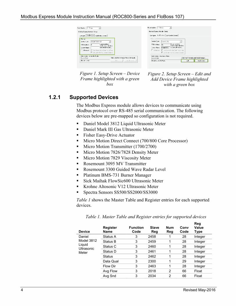
Additionally, to ensure that the flow of data between the module and flow computer has sufficient processing and communication time, the module prevents you from entering data in certain fields on screens (such as "Add Device" and "Edit/Delete Device" tabs on the Setup configurations screen). This “locking” feature helps you to select components in the proper order. A green box around the button or frame indicates that it is active. For example, in the Add Device tab of the Setup configurations screen, if you select a device to add and then click Apply, the module locks the Device section of the screen and activates the Edit and Add Device buttons. At this point, you can only click Add Device to add the device you select, or click Edit to unlock the Device frame and make any changes. See Figures 1 and 2.
Modbus Express Module Instruction Manual (ROC800-Series and FloBoss 107)
4 Revised May-2016
Figure 1. Setup Screen – Device Frame highlighted with a green
box
Figure 2. Setup Screen – Edit and
Add Device Frame highlighted with a green box
1.2.1 Supported Devices The Modbus Express module allows devices to communicate using Modbus protocol over RS-485 serial communication. The following devices below are pre-mapped so configuration is not required.
Daniel Model 3812 Liquid Ultrasonic Meter Daniel Mark III Gas Ultrasonic Meter Fisher Easy-Drive Actuator Micro Motion Direct Connect (700/800 Core Processor) Micro Motion Transmitter (1700/2700) Micro Motion 7826/7828 Density Meter Micro Motion 7829 Viscosity Meter Rosemount 3095 MV Transmitter Rosemount 3300 Guided Wave Radar Level Platinum BMS-731 Burner Manager Sick Maihak FlowSic600 Ultrasonic Meter Krohne Altosonic V12 Ultrasonic Meter Spectra Sensors SS500/SS2000/SS3000
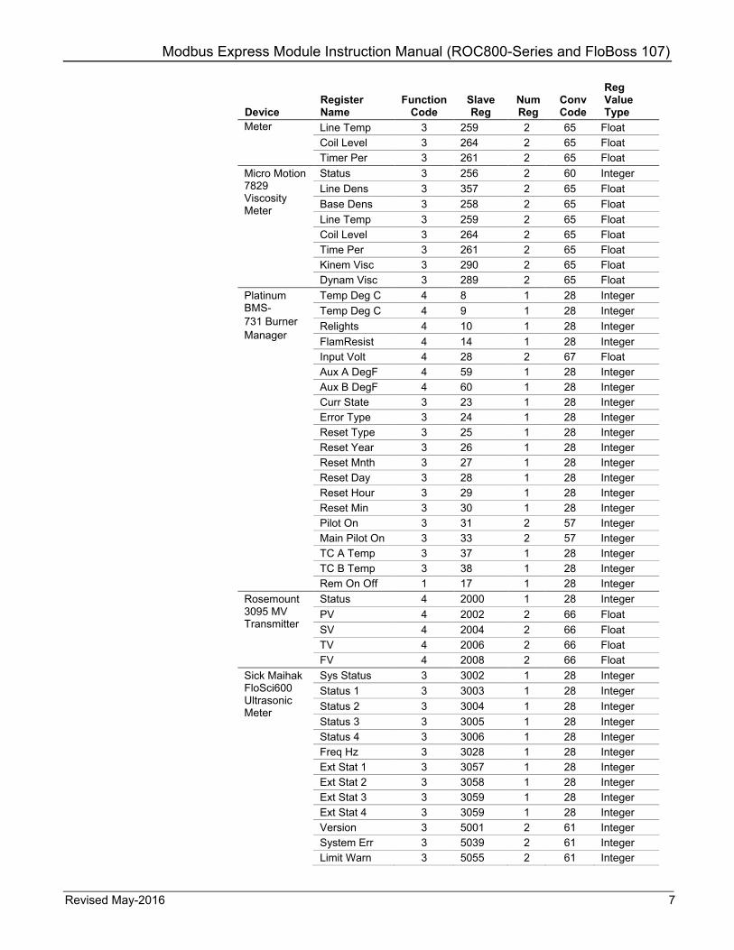
Table 1 shows the Master Table and Register entries for each supported devices.
Table 1. Master Table and Register entries for supported devices
Device Register Name
Function Code
Slave Reg
Num Reg
Conv Code
Reg Value Type
Daniel Model 3812 Liquid Ultrasonic Meter
Status A 3 2458 1 28 Integer Status B 3 2459 1 28 Integer Status C 3 2460 1 28 Integer Status D 3 2461 1 28 Integer Status 3 2462 1 28 Integer
Data Qual 3 2300 1 29 Integer Flow Dir 3 2463 1 28 Integer Avg Flow 3 2018 2 66 Float Avg Snd 3 2034 2 66 Float

Modbus Express Module Instruction Manual (ROC800-Series and FloBoss 107)
Revised May-2016 5
Device Register Name
Function Code
Slave Reg
Num Reg
Conv Code
Reg Value Type
Avg Flow 3 2018 2 66 Float Q Meter 3 2042 2 66 Float Q Flow 3 2056 2 66 Float Freq 1 KF 3 2516 2 66 Float Freq ChA 3 2504 2 66 Float Freq 1 KF 3 2566 2 66 Float Freq ChA 3 2554 2 66 Float CPU FW Ver 3 9006 1 29 Integer Fwd A Hour 3 4110 1 29 Integer Rev A Hour 3 4112 1 29 Integer Fwd A Day 3 4160 1 29 Integer Rev A Day 3 4162 1 29 Integer Fwd A Hour 3 4210 1 29 Integer Rev A Hour 3 4212 1 29 Integer Fwd A Day 3 4260 1 29 Integer Rev A Day 3 4262 1 29 Integer Flow Time 3 2106 2 66 Float Flow Time 3 2108 2 66 Float Daniel Mark III Gas Ultrasonic Meter
Sys Status 3 10953 1 28 Integer Path A Sta 3 10954 1 28 Integer Path B Sta 3 10955 1 28 Integer Path C Sta 3 10956 1 28 Integer Path D Sta 3 10957 1 28 Integer
CPU SW Ver 3 11000 1 29 Integer Data Qual 3 10584 1 29 Integer Freq 1 3 12468 2 67 Float Freq 2 3 12518 2 67 Float K-Factor 1 3 12472 2 67 Float K-Factor 2 3 12522 2 67 Float Velocity 3 13574 2 67 Float Spd of Snd 3 13594 2 67 Float Ucorr Rate 3 13624 2 67 Float Corr Rate 3 13638 2 67 Float Fisher Easy-Drive Actuator
Pos Demand 3 0 1 28 Integer Reset Diag 3 1 1 28 Integer Recal Dmd 3 2 1 28 Integer
A Cal 0% 3 3 1 28 Integer A Cal 100% 3 4 1 28 Integer Actual Pos 3 9 1 28 Integer Actual Dmd 3 10 1 28 Integer Num Cycles 3 12 2 63 Integer Tm Running 3 14 2 63 Integer Tm Open 3 16 2 63 Integer Tm Closed 3 18 2 63 Integer A IP Val 3 24 1 28 Integer Ctr Src 3 33 1 28 Integer Loss D Pos 3 34 1 28 Integer Deadband 3 35 1 28 Integer LowT Ctoff 3 36 1 28 Integer

Modbus Express Module Instruction Manual (ROC800-Series and FloBoss 107)
6 Revised May-2016
Device Register Name
Function Code
Slave Reg
Num Reg
Conv Code
Reg Value Type
Comm Tmout 3 37 1 28 Integer GO TO POS 6 0 1 28 Integer Krohne Altosonic V12 Ultrasonic Meter
SNR 1 AB 4 7025 2 65 Float SNR 2 AB 4 7027 2 65 Float SNR 3 AB 4 7029 2 65 Float SNR 4 AB 4 7031 2 65 Float SNR 5 AB 4 7033 2 65 Float
SNR 6 AB 4 7035 2 65 Float SNR 1 BA 4 7037 2 65 Float SNR 2 BA 4 7039 2 65 Float SNR 3 BA 4 7041 2 65 Float SNR 4 BA 4 7043 2 65 Float SNR 5 BA 4 7045 2 65 Float SNR 6 BA 4 7047 2 65 Float Flow Rate 4 7055 2 65 Float Velocity 4 7057 2 65 Float Spd of Snd 4 7059 2 65 Float Vel Path 1 4 7061 2 65 Float Vel Path 2 4 7063 2 65 Float Vel Path 3 4 7065 2 65 Float Vel Path 4 4 7067 2 65 Float Vel Path 5 4 7069 2 65 Float Vel Path 6 4 7071 2 65 Float Spd Snd 1 4 7073 2 65 Float Spd Snd 2 4 7075 2 65 Float Spd Snd 3 4 7077 2 65 Float Spd Snd 4 4 7079 2 65 Float Spd Snd 5 4 7081 2 65 Float Spd Snd 6 4 7083 2 65 Float Micro Motion Direct Connect (700/800) and Micro Motion Transmitter (1700/2700)
Meter Zero 1 4 1 28 Integer Flow Dir 1 65 1 28 Integer Status 3 244 2 70 Float Mass Rate 3 246 2 70 Float Density 3 248 2 70 Float Temp 3 250 2 70 Float Vol Rate 3 252 2 70 Float
Mass Total 3 258 2 70 Float Vol Total 3 260 2 70 Float Mass Inv 3 262 2 70 Float Vol Inv 3 264 2 70 Float Pr Corr Fl 3 266 2 70 Float Pr Corr Dn 3 268 2 70 Float Tube Freq 3 284 2 70 Float L Pckf Vol 3 288 2 70 Float Drive Gain 3 290 2 70 Float Mass Fl Zr 3 292 2 70 Float Micro Motion 7826/7828 Density
Status 3 256 2 60 Integer Cor Line D 3 257 2 65 Float Cor Base D 3 258 2 65 Float
Modbus Express Module Instruction Manual (ROC800-Series and FloBoss 107)
Revised May-2016 7
Device Register Name
Function Code
Slave Reg
Num Reg
Conv Code
Reg Value Type
Meter Line Temp 3 259 2 65 Float Coil Level 3 264 2 65 Float Timer Per 3 261 2 65 Float Micro Motion 7829 Viscosity Meter
Status 3 256 2 60 Integer Line Dens 3 357 2 65 Float Base Dens 3 258 2 65 Float Line Temp 3 259 2 65 Float
Coil Level 3 264 2 65 Float Time Per 3 261 2 65 Float Kinem Visc 3 290 2 65 Float Dynam Visc 3 289 2 65 Float Platinum BMS- 731 Burner Manager
Temp Deg C 4 8 1 28 Integer Temp Deg C 4 9 1 28 Integer Relights 4 10 1 28 Integer FlamResist 4 14 1 28 Integer
Input Volt 4 28 2 67 Float Aux A DegF 4 59 1 28 Integer Aux B DegF 4 60 1 28 Integer Curr State 3 23 1 28 Integer Error Type 3 24 1 28 Integer Reset Type 3 25 1 28 Integer Reset Year 3 26 1 28 Integer Reset Mnth 3 27 1 28 Integer Reset Day 3 28 1 28 Integer Reset Hour 3 29 1 28 Integer Reset Min 3 30 1 28 Integer Pilot On 3 31 2 57 Integer Main Pilot On 3 33 2 57 Integer TC A Temp 3 37 1 28 Integer TC B Temp 3 38 1 28 Integer Rem On Off 1 17 1 28 Integer Rosemount 3095 MV Transmitter
Status 4 2000 1 28 Integer PV 4 2002 2 66 Float SV 4 2004 2 66 Float
TV 4 2006 2 66 Float FV 4 2008 2 66 Float Sick Maihak FloSci600 Ultrasonic Meter
Sys Status 3 3002 1 28 Integer Status 1 3 3003 1 28 Integer Status 2 3 3004 1 28 Integer Status 3 3 3005 1 28 Integer
Status 4 3 3006 1 28 Integer Freq Hz 3 3028 1 28 Integer Ext Stat 1 3 3057 1 28 Integer Ext Stat 2 3 3058 1 28 Integer Ext Stat 3 3 3059 1 28 Integer Ext Stat 4 3 3059 1 28 Integer Version 3 5001 2 61 Integer System Err 3 5039 2 61 Integer Limit Warn 3 5055 2 61 Integer

Modbus Express Module Instruction Manual (ROC800-Series and FloBoss 107)
8 Revised May-2016
Device Register Name
Function Code
Slave Reg
Num Reg
Conv Code
Reg Value Type
Uncor Rate 3 7000 2 66 Float Velocity 3 7003 2 66 Float Spd of Snd 3 7002 2 66 Float Meter Fact 3 7026 2 66 Float Spectra Sensors SS500 / SS2000 / SS3000
Concentrat 3 7000 2 65 Float Temp 3 7002 2 65 Float Pressure 3 7004 2 65 Float Spply Volt 3 7006 2 65 Float PkD1 Mid 3 7008 2 65 Float FW Version 3 7112 2 65 Float S Factor 3 7200 2 65 Float Alm Flags 3 5000 2 64 Integer
1.2.2 Module and Device Wiring Connect the device(s) to the communications port on the module using 16 to 24 AWG wiring. Figures 3 and 4 show sample wirings between the module and several sensor types. Figures 5 through 17 show the wiring diagrams for each supported devices.
Figure 3. Module Wiring FB107 (Generic)
FIELDDEVICE
EXTERNALPOWERPOWER
EXTERNAL
-+
DEVICEFIELD
POWEREXTERNAL
DEVICEFIELD
USER SUPPLIED
120 OHMTERMINATION RESISTOR
+ +
A
B
A
B
A
B
- -

Modbus Express Module Instruction Manual (ROC800-Series and FloBoss 107)
Revised May-2016 9
Figure 4. Module Wiring for ROC800 (Generic)
Figure 5. Wiring diagram for Daniel Model
3812 Liquid Ultrasonic Meter
Figure 6. Wiring diagram for Daniel Mark III
Gas Ultrasonic Meter
Note: S1, Port B - Half Duplex Set, Term On
Figure 7. Wiring diagram for Fisher Easy-Drive Actuator
Figure 8. Wiring diagram for Micro Motion Direct Connect 700 Core Processor and 800
Enhanced Core Processor
FIELDDEVICE
EXTERNALPOWERPOWER
EXTERNAL
-+
DEVICEFIELD
POWEREXTERNAL
DEVICEFIELD
USER SUPPLIED
120 OHMTERMINATION RESISTOR
+ +
A
B
A
B
A
B
- -

Modbus Express Module Instruction Manual (ROC800-Series and FloBoss 107)
10 Revised May-2016
Figure 9. Wiring diagram for 1700 / 2700
Micro Motion Transmitter
Figure 10. Wiring diagram for Micro Motion
7826 / 7828 Density Meter
Figure 11. Wiring diagram for Micro Motion
7829 Viscosity Meter
Figure 12. Wiring diagram for Platinum BMS-
731 Burner Manager
Figure 13. Wiring diagram for Rosemount 3300
Guided Wave Radar Level
Figure 14. Wiring diagram for Rosemount 3095
MV Transmitter
Modbus Express Module Instruction Manual (ROC800-Series and FloBoss 107)
Revised May-2016 11
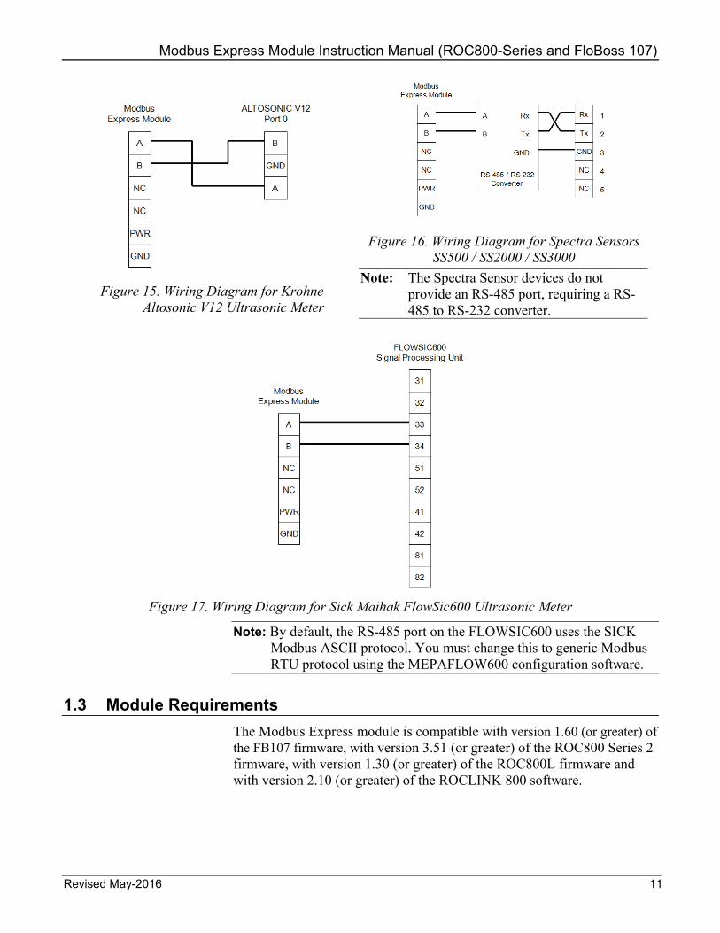
Figure 15. Wiring Diagram for Krohne
Altosonic V12 Ultrasonic Meter
Figure 16. Wiring Diagram for Spectra Sensors
SS500 / SS2000 / SS3000 Note: The Spectra Sensor devices do not
provide an RS-485 port, requiring a RS-485 to RS-232 converter.
Figure 17. Wiring Diagram for Sick Maihak FlowSic600 Ultrasonic Meter
Note: By default, the RS-485 port on the FLOWSIC600 uses the SICK Modbus ASCII protocol. You must change this to generic Modbus RTU protocol using the MEPAFLOW600 configuration software.
1.3 Module Requirements The Modbus Express module is compatible with version 1.60 (or greater) of the FB107 firmware, with version 3.51 (or greater) of the ROC800 Series 2 firmware, with version 1.30 (or greater) of the ROC800L firmware and with version 2.10 (or greater) of the ROCLINK 800 software.

Modbus Express Module Instruction Manual (ROC800-Series and FloBoss 107)
12 Revised May-2016
[This page is intentionally left blank.]
Modbus Express Module Instruction Manual (ROC800-Series and FloBoss 107)
Revised May-2016 13
Chapter 2 – Installation
This chapter provides instructions for installing the Modbus Express module. Read Section 1.3 of this manual for the module requirements.
Note: You can install only one Modbus Express module in either the ROC800 or the FB107.
2.1 Installing the Application Module The application module occupies the standard footprint of an FB107 or ROC800 I/O or communications module.
To install the module in ROC800, place it in any empty slot on the ROC800. To install the module in FB107, remove power to the FB107. Place the module in an empty slot (1 through 7) on the FB107 and reapply power.
To ensure that the FB107 and ROC800 recognizes the module, you must perform a warm start (ROC > Flags > Warm Start).
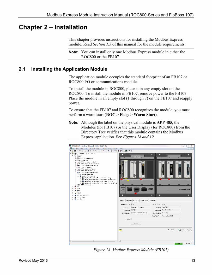
Note: Although the label on the physical module is APP 485, the Modules (for FB107) or the User Display (for ROC800) from the Directory Tree verifies that this module contains the Modbus Express application. See Figures 18 and 19.
Figure 18. Modbus Express Module (FB107)

Modbus Express Module Instruction Manual (ROC800-Series and FloBoss 107)
14 Revised May-2016
Figure 19. Modbus Express Module (ROC800)
Once you have verified that the ROC800 has recognized the Modbus Express module, proceed to Chapter 3 to begin configuring the module.
2.2 Updating the Application Module The ROC800 version of the Modbus Express module is factory-loaded to use displays 69, 70, 71, and 72. If you have previously installed another application that already uses one of those displays, you must update the module’s firmware using the Modbus Express Module 1.01 ALT.BIN file, which provides the same functionality using displays 73, 74, 75, and 76. Contact Technical Support for a copy of the ALT.BIN file.
For further information on updating firmware, refer to Section 9.1 Update Firmware, in Chapter 9 of the ROCLINK 800™ Configuration Software User Manual (for ROC800 Series), (part D301250X012).
2.3 MPU Loading Threshold (ROC800) To maximize the performance of your ROC800 device, always verify the performance of specific application combinations before using them in the field to ensure the MPU load typically remains below 85% with peak MPU loading levels below 95%.

Modbus Express Module Instruction Manual (ROC800-Series and FloBoss 107)
Revised May-2016 15
To check the current MPU load at any time, select ROC > Information > Other Information and review the value in the MPU loading field.
Figure 20. MPU Loading

Modbus Express Module Instruction Manual (ROC800-Series and FloBoss 107)
16 Revised May-2016
[This page is intentionally left blank.]

Modbus Express Module Instruction Manual (ROC800-Series and FloBoss 107)
Revised May-2016 17
Chapter 3 – Configuration
After you have successfully installed the Modbus Express module in the FB107 or ROC800, you configure the module using four module-specific screens (Setup, Master Table, Registers, and Expanded Registers). Use the Modbus Master Configuration screen to configure communications with the device(s).
You must configure the module before you can establish communications with the device(s). To configure the module (after logging onto ROCLINK 800 and successfully installing the module) proceed through the screens as shown in this chapter.
Note: The configurations screens of the Modbus Express module for both the ROC800 and FB107 platform are identical.
You can access the module-specific screens from the main ROCLINK 800 screen:
Figure 21. ROCLINK 800 (FB107)

Modbus Express Module Instruction Manual (ROC800-Series and FloBoss 107)
18 Revised May-2016
Figure 22. ROCLINK 800 (ROC800)
3.1 Setup Screen Use this screen to configure the communications with Modbus devices and to add, edit, or delete Modbus devices. The Setup screen has three tabs (Configure, Add Device, and Edit/Delete Device).
To Access this screen: 1. From the Directory Tree, double-click User Display if you use
ROC800 or Modules > Slot #, Modbus Express Mod if you use FB107.
Note: For FB107, the Slot # indicates the slot where you install your Modbus Express module. For example, if you install your Modbus Express module in slot 2, then you double-click Module > Slot 2, Modbus Express Mod from the directory tree.
2. Double-click Display #69 - Modbus Express Module – Setup. The setup screen displays:
Modbus Express Module Instruction Manual (ROC800-Series and FloBoss 107)
Revised May-2016 19
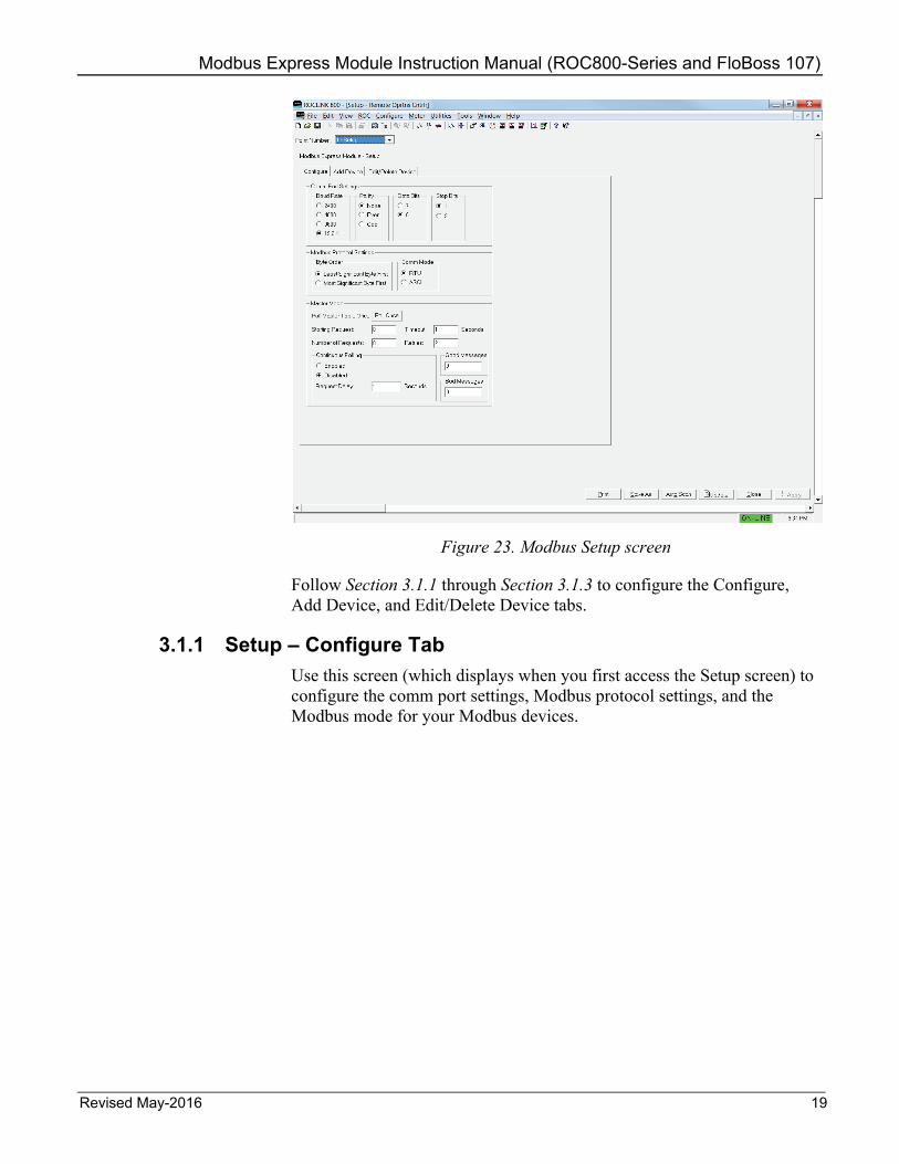
Figure 23. Modbus Setup screen
Follow Section 3.1.1 through Section 3.1.3 to configure the Configure, Add Device, and Edit/Delete Device tabs.
3.1.1 Setup – Configure Tab Use this screen (which displays when you first access the Setup screen) to configure the comm port settings, Modbus protocol settings, and the Modbus mode for your Modbus devices.

Modbus Express Module Instruction Manual (ROC800-Series and FloBoss 107)
20 Revised May-2016
Figure 24. Setup – Configure screen
1. Review the values in the following fields: Field Description Point Number Selects the Modbus Express screen to
configure. Available option is Setup configuration screen only.
Baud Rate Sets, in bits per second, the baud rate this comm port uses when transmitting and receiving data. The default value is 19.2 kbps.
Parity Indicates whether the communications controller performs parity checks. The parity value can be odd, even, or none. The default value is None.
Data Bits Sets the number of data bits contained in an asynchronous byte or character. The default is 8.
Stop Bits Sets the number of stop bits contained in an asynchronous byte or character. The default is 1.
Modbus Express Module Instruction Manual (ROC800-Series and FloBoss 107)
Revised May-2016 21
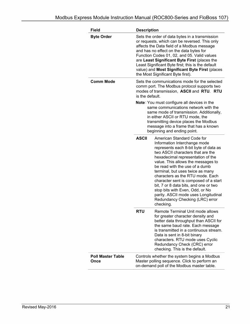
Field Description Byte Order Sets the order of data bytes in a transmission
or requests, which can be reversed. This only affects the Data field of a Modbus message and has no effect on the data bytes for Function Codes 01, 02, and 05. Valid values are Least Significant Byte First (places the Least Significant Byte first; this is the default value) and Most Significant Byte First (places the Most Significant Byte first).
Comm Mode Sets the communications mode for the selected comm port. The Modbus protocol supports two modes of transmission, ASCII and RTU. RTU is the default. Note: You must configure all devices in the
same communications network with the same mode of transmission. Additionally, in either ASCII or RTU mode, the transmitting device places the Modbus message into a frame that has a known beginning and ending point.
ASCII American Standard Code for Information Interchange mode represents each 8-bit byte of data as two ASCII characters that are the hexadecimal representation of the value. This allows the messages to be read with the use of a dumb terminal, but uses twice as many characters as the RTU mode. Each character sent is composed of a start bit, 7 or 8 data bits, and one or two stop bits with Even, Odd, or No parity. ASCII mode uses Longitudinal Redundancy Checking (LRC) error checking.
RTU Remote Terminal Unit mode allows for greater character density and better data throughput than ASCII for the same baud rate. Each message is transmitted in a continuous stream. Data is sent in 8-bit binary characters. RTU mode uses Cyclic Redundancy Check (CRC) error checking. This is the default.
Poll Master Table Once
Controls whether the system begins a Modbus Master polling sequence. Click to perform an on-demand poll of the Modbus master table.
Modbus Express Module Instruction Manual (ROC800-Series and FloBoss 107)
22 Revised May-2016
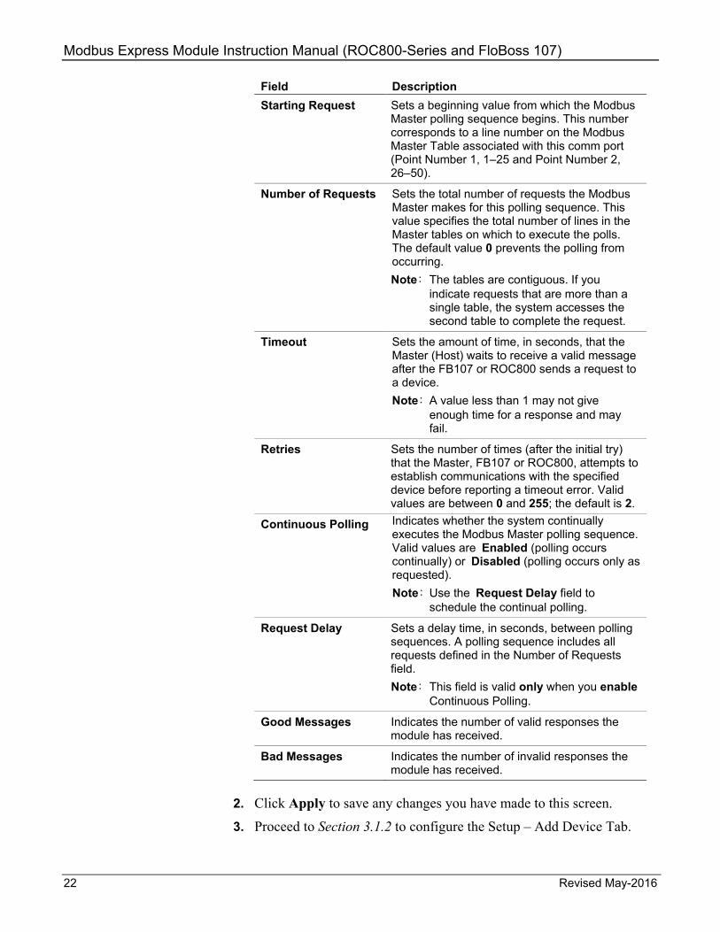
Field Description Starting Request Sets a beginning value from which the Modbus
Master polling sequence begins. This number corresponds to a line number on the Modbus Master Table associated with this comm port (Point Number 1, 1–25 and Point Number 2, 26–50).
Number of Requests Sets the total number of requests the Modbus Master makes for this polling sequence. This value specifies the total number of lines in the Master tables on which to execute the polls. The default value 0 prevents the polling from occurring. Note: The tables are contiguous. If you
indicate requests that are more than a single table, the system accesses the second table to complete the request.
Timeout Sets the amount of time, in seconds, that the Master (Host) waits to receive a valid message after the FB107 or ROC800 sends a request to a device. Note: A value less than 1 may not give
enough time for a response and may fail.
Retries Sets the number of times (after the initial try) that the Master, FB107 or ROC800, attempts to establish communications with the specified device before reporting a timeout error. Valid values are between 0 and 255; the default is 2.
Continuous Polling Indicates whether the system continually executes the Modbus Master polling sequence. Valid values are Enabled (polling occurs continually) or Disabled (polling occurs only as requested). Note: Use the Request Delay field to
schedule the continual polling.
Request Delay Sets a delay time, in seconds, between polling sequences. A polling sequence includes all requests defined in the Number of Requests field. Note: This field is valid only when you enable
Continuous Polling.
Good Messages Indicates the number of valid responses the module has received.
Bad Messages Indicates the number of invalid responses the module has received.
2. Click Apply to save any changes you have made to this screen.
3. Proceed to Section 3.1.2 to configure the Setup – Add Device Tab.

Modbus Express Module Instruction Manual (ROC800-Series and FloBoss 107)
Revised May-2016 23
3.1.2 Setup – Add Device Tab Use this screen to select and configure Modbus device. To access the screen:
1. Select the Add Device tab on the Setup Screen. The Add Device screen displays:
Note: The green box around the section indicates that the section is active and configurable.
Figure 25. Setup – Add Device screen

Modbus Express Module Instruction Manual (ROC800-Series and FloBoss 107)
24 Revised May-2016
Figure 26. Setup – Add Device screen (Advanced mode – enabled)
2. Review the values in the following fields: Field Description Device Type Selects the type of device to be added. Click
to display all available devices.
RTU Address Sets the RTU address for the slave device to be queried.
Custom Name Sets a custom tag up to 10 characters in length you can define for the device.
Advanced Enables the advanced options for adding a device.
Set Master Mode Start/Num Reqs.
Allows master table adjustments. This parameter activates only when you select the Advanced option.
Set Comm Port to Device Defaults
Allows communication settings adjustments This parameter activates only when you select the Advanced option.
Master Table Start Sets the location in master table to where the device is added. This parameter shows only when you select the Advanced option.
Register Start Sets the location in registers table to where the device is added. This parameter shows only when you select the Advanced option.
Modbus Express Module Instruction Manual (ROC800-Series and FloBoss 107)
Revised May-2016 25
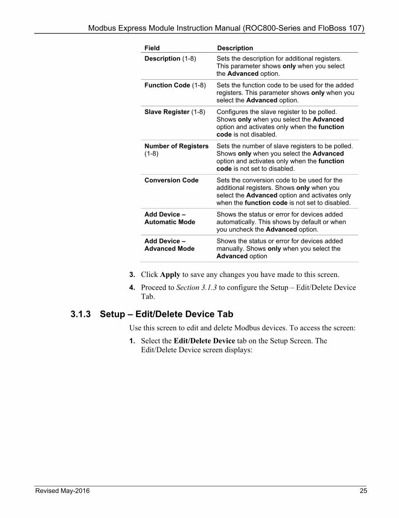
Field Description Description (1-8) Sets the description for additional registers.
This parameter shows only when you select the Advanced option.
Function Code (1-8) Sets the function code to be used for the added registers. This parameter shows only when you select the Advanced option.
Slave Register (1-8) Configures the slave register to be polled. Shows only when you select the Advanced option and activates only when the function code is not disabled.
Number of Registers (1-8)
Sets the number of slave registers to be polled. Shows only when you select the Advanced option and activates only when the function code is not set to disabled.
Conversion Code Sets the conversion code to be used for the additional registers. Shows only when you select the Advanced option and activates only when the function code is not set to disabled.
Add Device – Automatic Mode
Shows the status or error for devices added automatically. This shows by default or when you uncheck the Advanced option.
Add Device – Advanced Mode
Shows the status or error for devices added manually. Shows only when you select the Advanced option
3. Click Apply to save any changes you have made to this screen.
4. Proceed to Section 3.1.3 to configure the Setup – Edit/Delete Device Tab.
3.1.3 Setup – Edit/Delete Device Tab Use this screen to edit and delete Modbus devices. To access the screen:
1. Select the Edit/Delete Device tab on the Setup Screen. The Edit/Delete Device screen displays:

Modbus Express Module Instruction Manual (ROC800-Series and FloBoss 107)
26 Revised May-2016
Figure 27. Setup – Edit/Delete Device screen
2. Review the values in the following fields: Field Description Device Type (1-6) Sets the device type.
RTU Address (1-6) Sets the RTU address for the device to be queried.
Custom Name (1-6) Shows the custom name entered from Add device tab.
Master Table Start (1-6)
Shows where in the Master Table this device's entries begin.
Master Table End (1-6)
Shows where in the Master Table that this device's entries end.
Register Start (1-6) Shows where in the Registers Table this device's entries begin. A value of 0 indicates the device is not configured.
Register End (1-6) Shows where in the Registers Table this device's entries end. A value of 0 indicates the device is not configured.
Pack Master Table Deletes empty Master Table fields and makes the entries contiguous.
Pack Registers Deletes empty Registers Table fields and makes the entries contiguous.
Status/Error Show the status error of the added devices

Modbus Express Module Instruction Manual (ROC800-Series and FloBoss 107)
Revised May-2016 27
3. Click Apply to save any changes you have made to this screen.
4. Click Close to return to the main ROCLINK 800 screen. Proceed to Section 3.2 to configure the Master Table Screen.
3.2 Master Table Screen Use this screen to configure the Modbus Express master table. The module uses 50 Master Table entries (25 for each logical). To access this screen:
1. From the Directory Tree, double-click User Display if you use ROC800 or Modules > Slot #, Modbus Express Mod if you use FB107.
Note: For FB107, the Slot # indicates the slot where you install your Modbus Express module. For example, if you install your Modbus Express module in slot 2, then you double-click Module > Slot 2, Modbus Express Mod from the directory tree.
2. Double-click Display #70 – Modbus Express Module – Master Table. The setup screen displays:
Figure 28. Master Table screen
3. Review the values in the following fields:

Modbus Express Module Instruction Manual (ROC800-Series and FloBoss 107)
28 Revised May-2016
Field Description Point Number Selects the Modbus master table to configure.
Click to display all available master tables.
RTU Address (1-25), (26-50)
Sets the RTU address for the device to be queried. Note: The Master Table screen has two
continuous sections; rows 1-25 and rows 26- 50. Rows 1-25 are shown by default. Select 2 - MTbl 26-50 using the Point Number field to access rows 26-50.
Function Code (1-25), (26-50)
Sets the Modbus function code to be sent to the device. Click to display all valid function codes. Note: The Master Table screen has two
continuous sections; rows 1-25 and rows 26- 50. Rows 1-25 are shown by default. Select 2 - MTbl 26-50 using the Point Number field to access rows 26-50.
Slave Register (1-25), (26-50)
Sets the starting register number from which data is drawn from the device. Valid values are 1 to 65535. Note: The Master Table screen has two
continuous sections; rows 1-25 and rows 26- 50. Rows 1-25 are shown by default. Select 2 - MTbl 26-50 using the Point Number field to access rows 26-50.
Master Register (1-25), (26-50)
Sets the starting register number into which data is stored on the device. Valid values are 1 to 65535. Notes: This number corresponds to the Value field
on the Register screen. The Master Table screen has two
continuous sections; rows 1-25 and rows 26- 50. Rows 1-25 are shown by default. Select 2 - MTbl 26-50 using the Point Number field to access rows 26-50.
Number of Registers (1-25), (26-50)
Sets the total number of registers to poll. Note: The Master Table screen has two
continuous sections; rows 1-25 and rows 26- 50. Rows 1-25 are shown by default. Select 2 - MTbl 26-50 using the Point Number field to access rows 26-50.

Modbus Express Module Instruction Manual (ROC800-Series and FloBoss 107)
Revised May-2016 29
Field Description Conversion Code (1-25), (26-50)
Sets the type of conversion performed (if any) on data before it is either sent to the host or written to the FB107 or ROC800. The conversions accommodate differences in data types between the devices. Conversion codes affect Function Codes 3, 4, 6, and 15. Click to display all valid conversion codes: 0 = No Conversion 25 = Any type to FLOAT 26 = Any type to signed short 27 = Any type to signed long 28 = Any type to unsigned short 29 = Any type to unsigned long 30 = Any type to unsigned byte 57 = Any type to signed long 0,1,2,3 58 = Any type to signed long 1,0,3,2 59 = Any type to signed long 2,3,0,1 60 = Any type to signed long 3,2,1,0 61 = Any type to unsigned long 0,1,2,3 62 = Any type to unsigned long 1,0,3,2 63 = Any type to unsigned long 2,3,0,1 64 = Any type to unsigned long 3,2,1,0 65-72 = IEEE Floating Point Number Note: The Master Table screen has two
continuous sections; rows 1-25 and rows 26- 50. Rows 1-25 are shown by default. Select 2 - MTbl 26-50 using the Point Number field to access rows 26-50.
Comm Status (1-25), (26-50)
This read-only field shows the status of the query. Note: The Master Table screen has two
continuous sections; rows 1-25 and rows 26- 50. Rows 1-25 are shown by default. Select 2 - MTbl 26-50 using the Point Number field to access rows 26-50.
0 Inactive 1 Timeout Error 2 Addr Check 3 Function Code Error. 4 Num of Exp Bytes 5 RCV Slave Resp 6 CRC/LRC Check 7 CRC/LRC Check 8 Valid Response Received 128 Write Data Error 129 Acc Dev Data 130 Master Table Error 131 Trans Timeout 144 Tx/Rx Buff Ovr 145 Invalid Func #
Modbus Express Module Instruction Manual (ROC800-Series and FloBoss 107)
30 Revised May-2016
Field Description Device (1-25), (26-50) Shows the custom name of the device.
Note: The Master Table screen has two continuous sections; rows 1-25 and rows 26- 50. Rows 1-25 are shown by default. Select 2 - MTbl 26-50 using the Point Number field to access rows 26-50.
4. Click Apply to save any changes you have made to this screen.
5. Click Close to return to the ROCLINK 800 screen. Proceed to Section 3.3 to configure the Register screen.
3.3 Registers Screen The module uses 200 registers (50 for each logical) to store data read from or written to the devices. All register values are in float or register data types that depend on the conversion codes you use. To access this screen:
1. From the Directory Tree, double-click User Display if you use ROC800 or Modules > Slot #, Modbus Express Mod if you use FB107.
Note: For FB107, the Slot # indicates the slot where you install your Modbus Express module. For example, if you install your Modbus Express module in slot 2, then you double-click Module > Slot 2, Modbus Express Mod from the directory tree.
2. Double-click Display #71 – Modbus Express Module – Registers. The Registers screen displays:

Modbus Express Module Instruction Manual (ROC800-Series and FloBoss 107)
Revised May-2016 31
Figure 29. Registers screen
3. Review—and change as necessary—the values in the following fields:
Field Description
Point Number Selects one of the four register logicals. Click to display all available Registers tables.
Tag Sets a unique identifier for the selected table.
Register Value Integer (1-50), (51-100), (101-150), and (151-200)
Shows or sets the integer value for each register. Note: The Registers table screen has four
continuous sections; rows 1-50, rows 51-100, rows 101-150, and rows 151-200. Rows 1-50 are shown by default. Select 2 - Reg 51-100 using the Point Number field to access rows 51-100. Use the other Point Number options to access the rest of the rows.
Register Value Float (1-50), (51-100), (101-150), and (151-200)
Shows or sets the floating value for each register. Note: The Registers table screen has four
continuous sections; rows 1-50, rows 51-100, rows 101-150, and rows 151-200. Rows 1-50 are shown by default. Select 2 - Reg 51-100 using the Point Number field to access rows 51-100. Use the other Point Number options to access the rest of the rows.

Modbus Express Module Instruction Manual (ROC800-Series and FloBoss 107)
32 Revised May-2016
Field Description
Register Tag (1-50), (51-100), (101-150), and (151-200)
Shows or sets a unique identifier for each register. Note: The Registers table screen has four
continuous sections; rows 1-50, rows 51-100, rows 101-150, and rows 151-200. Rows 1-50 are shown by default. Select 2 - Reg 51-100 using the Point Number field to access rows 51-100. Use the other Point Number options to access the rest of the rows.
Device (1-50), (51-100), (101-150), and (151-200)
Shows the device’s custom name. Note: The Registers table screen has four
continuous sections; rows 1-50, rows 51-100, rows 101-150, and rows 151-200. Rows 1-50 are shown by default. Select 2 - Reg 51-100 using the Point Number field to access rows 51-100. Use the other Point Number options to access the rest of the rows.
4. Click Close to return to the ROCLINK 800 screen. Proceed to Section 3.4 to configure the Expanded Registers screen.
3.4 Expanded Regs Screen Use this screen to configure the Expanded Registers. To access this screen:
1. From the Directory Tree, double-click User Display if you use ROC800 or Modules > Slot #, Modbus Express Mod if you use FB107.
Note: For FB107, the Slot # indicates the slot where you install your Modbus Express module. For example, if you install your Modbus Express module in slot 2, then you double-click Module > Slot 2, Modbus Express Mod from the directory tree.
2. Double-click Display #72 – Modbus Express Module – Expanded Regs. The Expanded Registers screen displays:

Modbus Express Module Instruction Manual (ROC800-Series and FloBoss 107)
Revised May-2016 33
Figure 30. Expanded Registers screen, Register Type – Disabled
Figure 31. Expanded Registers screen, Register Type – Floating Point

Modbus Express Module Instruction Manual (ROC800-Series and FloBoss 107)
34 Revised May-2016
Figure 32. Expanded Registers screen, Register Type – Integer
Figure 33. Expanded Registers screen, Register Type – Digital
3. Review—and change as necessary—the values in the following fields:

Modbus Express Module Instruction Manual (ROC800-Series and FloBoss 107)
Revised May-2016 35
Field Description
Point Number Selects one of the twenty-five expanded register logicals.
Tag Sets a unique identifier for the selected expanded register table.
Link to Register Set which register the expanded register maps to.
Register Type Sets the register type.
Float Value Shows the live floating value for the register. This parameter shows only when Register Type is set to Floating Point.
Float Manual Value
Sets the manual float value for the register. This parameter shows only when Register Type is set to Floating Point.
Units Configures the units for the register. This parameter shows only when Register Type is set to Floating Point or Integer.
Floating Point Alarm
Sets the floating alarm. This parameter shows only when Register Type is set to Floating Point.
Low Alarm Value Sets the low alarm value. This parameter shows only when Register Type is set to Floating Point.
High Alarm Value Sets the high alarm value. This parameter shows only when Register Type is set to Floating Point or Integer.
Alarm Deadband Val.
Sets the alarm deadband value. This parameter shows only when Register Type is set to Floating Point or Integer.
Use Manual Float Override
Configures float override. This parameter shows only when Register Type is set to Floating Point or Integer.
Clip Float Value to Alarm Range
Sets float value clipping. This parameter shows only when Register Type is set to Floating Point.

Modbus Express Module Instruction Manual (ROC800-Series and FloBoss 107)
36 Revised May-2016
Field Description
Integer Value Shows the live integer value for the register. This parameter shows only when Register Type is set to Integer.
Integer Manual Value
Sets the manual integer value for the register. This parameter shows only when Register Type is set to Integer.
Integer Alarm Sets the integer alarm. This parameter shows only when Register Type is set to Integer.
Use Manual Int Override
Configures float override. This parameter shows only when Register Type is set to Integer.
Clip Int Value to Alarm Range
Sets integer clipping to alarm range. This parameter shows only when Register Type is set to Integer.
Show Integer Bits Shows integers as bits. This parameter shows only when Register Type is set to Integer.
Digital Status Enables or disables the digital register type. This parameter shows only when Register Type is set to Digital.
Digital Manual Status
Sets the manual digital status for the register. This parameter shows only when Register Type is set to Digital.
Digital Alarm Sets the digital alarm mode. The digital alarm selections include: disable alarms, enable on set alarms, enable on clear alarms, and enable on change alarms. This parameter shows only when Register Type is set to Digital.
Use Manual Digital Status Override
Enables manual digital status override. This parameter shows only when Register Type is set to Digital.

Modbus Express Module Instruction Manual (ROC800-Series and FloBoss 107)
Revised May-2016 37
Field Description
Invert Status Sets user interface options. This parameter displays only when you select Digital as the Register Type.
Active Alarms Shows the active alarms.
4. Click Close to return to the ROCLINK 800 screen. Proceed to Section 3.5 to save the configuration.
3.5 Saving the Configuration Whenever you modify or change the configuration, it is a good practice to save the final configuration to memory. To save the configuration:
1. Select ROC > Flags. The Flags screen displays:
Figure 34. Flags
2. Click Save Configuration. A verification message displays:
Figure 35. Save Verification
3. Click Yes to begin the save process. The Flash Write Status field on the Flags screen displays In Progress. When the process ends, the Flash Write Status field on the Flags screen displays Completed.

Modbus Express Module Instruction Manual (ROC800-Series and FloBoss 107)
38 Revised May-2016
4. Click Update on the Flags screen. This completes the process of saving your new configuration.
Note: For archive purposes, you should also save this configuration to your PC’s hard drive or a removable media (such as a flash drive) using the File > Save Configuration option on the ROCLINK 800 menu bar.

Modbus Express Module Instruction Manual (ROC800-Series and FloBoss 107)
Revised May-2016 39
Chapter 4 – Usage
This chapter describes quick start procedures and best practices for the Modbus Express module.
4.1 Quick Start Procedures
Adding a Device using Defaults Settings
From the Setup (Display #69) Configuration Screen, select the Add Device tab. A green box around the Device area indicates the portion of the display that is active.
1. Select a device from the Device Type pull-down menu and click the Apply button. (If the device is not using the factory default RTU address, you may optionally enter a custom address and a short custom name for the device. When you leave those fields empty, the Modbus Express module uses the program defaults.)
2. Click Update. The Status/Error box shows a Ready to Add message and the green box highlights the Edit and Add Device buttons.
Note: It takes time before the changes to propagate.
3. Click the Add Device button. After a moment, click Update. The Status/Error box displays Device Added message.
To verify if you successfully added the device, select the Edit/Delete Device tab from the Setup configuration screen. The screen shows all the devices you added with the default RTU Address and Custom Name. Other entries will show where in the Master Table the device is (start to end) and where in the Registers table the device registers are (start to end).
To begin polling, select the Configure tab of the Setup configuration screen, select Enabled from the Continuous Polling section and click Apply. Click Auto Scan to enable auto refresh of the display (remember to turn it off later), or click Update periodically to verify if the Good Messages count is increasing. If Bad Messages count increases, the device is either incorrectly wired or the comm port settings do not match the default communication settings the Modbus Express module uses.
The Modbus Express Module - Master Table (Display #70) screen also displays the entries of the device you add for further verification. The Comm Status and Comm Status Description columns indicate the statuses of each Master Table entry.
To check if the data are being polled from the device, view the Modbus Express Module - Registers (Display #71) screen and check if the Register entry of the device you add (either in the Integer column or Floating column) contains a value other than 0 or 0.0.

Modbus Express Module Instruction Manual (ROC800-Series and FloBoss 107)
40 Revised May-2016
Deleting a Device
To delete a device:
1. Open the Edit/Delete Device tab of the Setup (Display #69) configuration screen.
2. Check the box(es) of the device(s) you wanted to delete then click Apply.
3. Click Update. The Status/Error field should show Ready to Delete/Pack.
4. Click the Delete/Pack then wait a moment before you click Update. The Status/Error shows Device Deleted. This resets the device entries to empty or zero values.
Note: If desired, you can reset the Starting Request and Number of
Request Values using the Configure tab of the Setup (Display #69) configuration screen.
The Modbus Express module ignores empty Master Table entries.
Packing the Master Table/Registers
If you delete a device, you may leave gaps in the Master Table or Registers table. For example, if you add three devices and the first device takes Master Table entries 1-3, the second takes entries 4-9, and the third takes entries 10-15, the deletion of the second device leaves entries 4-9 empty.
If this is undesirable, you can check the Pack Master Table the Edit/Delete Device tab of the Modbus Express Module – Setup (Display #69) configuration screen to remove the empty entries. So, If you select Pack Master Table the first device still occupies entries 1-3, the former third device (originally entries 10-15) moves down to 5-10 and so on. The same thing applies to the Registers. This is to make more contiguous empty entries in the tables for adding new devices.
Disabling Automatic Comm Port or Master
Mode Configuration (Advanced Mode)
You can access the Advanced mode using the Add Device tab on the Modbus Express Module – Setup (Display #69) configuration screen. When you enable the Advanced mode, you can override the automatic setting of the Master Mode and the comm port settings.
When you uncheck the Set Master Mode Start/Num Reqs, the module prevents the automatic setting of the Master Mode such as setting the starting entry and the number of requests. When you uncheck the Set Comm Port to Defaults, the module prevents automatic configuration of the RS485.
If you add a device with different comm port settings than factory defaults, enable the Advanced mode and uncheck Set Comm Port Device Defaults.

Modbus Express Module Instruction Manual (ROC800-Series and FloBoss 107)
Revised May-2016 41
Overriding Custom Table Index Entries
(Advanced Mode)
When in Advanced mode, you can specify the location of your device’s entries in the Master Table and Registers table. If you specify Master Table Start to be 10, the device's Master Table entries start at 10. If a device is already present or if table spaces are not enough to accommodate the entries, the module returns an error. The same thing applies for device registers if you specify the Registers Start value.
This feature is applicable if you are sectioning your device’s entries in the Registers table. Since each Registers table is made up of four columns with 25 registers each (1-25, 26-75, etc.), you can add a device with less than 25 registers at entry 1, then the second device at entry 26, the third device at entry 76, and so on. This places the device entries in each column of the Registers table. This feature does not affect any process.
Adding Extra Modbus Registers
(Advanced Mode)
You can add up to eight additional Master Table entries for the device to enable polling of additional custom device registers. You can add any device registers. After you add the device, these registers appear in the Master Table and Registers entry for the device. If you delete the device, the module deletes these additional entries along with the default entries. The entries also move along with default entries if you pack the Master Table or Registers.
You can set a custom Register tag name for each extra modbus register. If you add and entry that polls multiple registers and only entered the description of first entry, the first Register uses the description name you enter plus a generated name of "+RegXXX" where "XXX" is an offset from the Register value. For example, if you enter “Volume” in the first register at register 3000, you first register name is “Volume” plus “+Reg3002”, “+Reg3004”, etc. You can change these generated names in the Modbus Express Modules - Registers (Display #71) configuration screen.
Manually Adding Master Table and
Registers
You can configure the Modbus Express module manually to add devices that are not natively supported by the module.
You must manually configure the Master Table start and end request entries to include any manual Master Table entries you add. You must enable Continuous Polling using the Configure tab of the Setup configuration screen.
Note: Any devices added by Express Mode will not overwrite any manual entries made by the user.

Modbus Express Module Instruction Manual (ROC800-Series and FloBoss 107)
42 Revised May-2016
4.2 Best Practices
Monitor the Good Messages Counter
When you enable Continuous Polling, the Good Messages counter increments for each line in the Master Table that is successfully polled. Any FST or other application that monitors Modbus Express Registers should verify that the Good Messages count is incrementing. If not, the Registers data may not be accurate. If you detect this situation, check the Master Table status.
Note: The baud rate of the comm port, the number of slave registers being polled in the Master Table, and the Request Delay value all impact how often the Good Messages counter increments. Reading the Register values may happen faster than the Modbus Express module can retrieve data from the device(s).
Check the Master Table Comm Status field
If you configure a device is with ten Master Table entries, each entry has a Comm Status value of 8 indicating that the last poll was successful. If Good Messages value appears to stop incrementing, an FST can scan through the Master Table Comm Status parameters for the device and look for error indicators.
Note: Both Good Messages and Comm Status should be checked to verify an error. In the event of some failure of the Modbus Express module, such as the disconnected cable, the Comm Status values remain in the last successful polling but do not indicate any error.
To verify errors:
1. Check if the Good Messages has incremented since the last check.
2. If Good Messages does not increment, check Master Table – Comm Status fields for the device being polled and check for non-successful status codes.
3. Handle this potential error as needed.

Modbus Express Module Instruction Manual (ROC800-Series and FloBoss 107)
Revised May-2016 43
Chapter 5 – Reference Materials
This section provides tables of information on the point types the Modbus Express module uses.
For the FB107:
Point Type 68 (Modbus Express Setup) Point Type 69 (Modbus Master Table) Point Type 70 (Modbus Registers) Point Type 71 (Modbus Expanded Registers)
For the ROC800:
Point Type 247 (Modbus Express Setup) Point Type 248 (Modbus Master Table) Point Type 249 (Modbus Registers) Point Type 250 (Modbus Expanded Registers)

Modbus Express Module Instruction Manual (ROC800-Series and FloBoss 107)
44 Revised May-2016
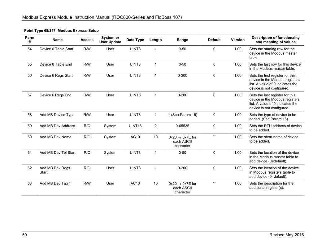
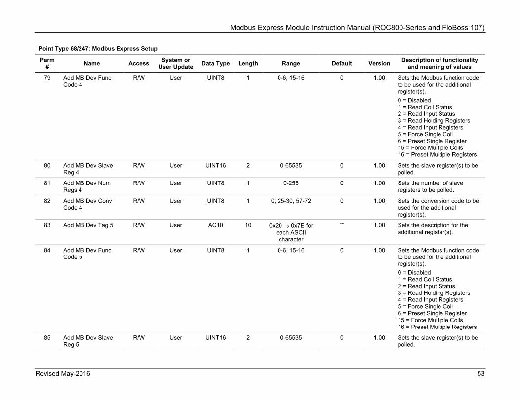
5.1 Point Type 68/247: Modbus Express Setup Point type 68 (for FB107) or 247 (for ROC800) contains configuration parameters for the Modbus Express App Module as a whole. There is a single logical for this point type.
Point Type 68/247: Modbus Express Setup
Parm # Name Access System or
User Update Data Type Length Range Default Version Description of functionality and meaning of values
0 Point Tag ID R/W User AC 10 0x20 → 0x7E for each ASCII character
"EasyMB Cfg" 1.00 Sets point type description
1 Baud Rate R/W User UINT8 1 0-3 3 1.00 Sets the baud rate for the RS-485 communication port 0 = 2400 1 = 4800 2 = 9600 3 = 19200
2 Data Bits R/W User UINT8 1 0-1 8 1.00 Sets the data bits. 7 = 7 bits 8 = 8 bits
3 Stop Bits R/W User UINT8 1 0-1 1 1.00 Sets the stop bits. 1 = 1 bit 2 = 2 bits
4 Parity R/W User UINT8 1 0-2 0 1.00 Sets the parity. 0 = None 1 = Odd 2 = Even
5 Transmission Mode R/W User UINT8 1 0-1 0 1.00 Controls the type of transmission mode desired. 0 = RTU Mode 1 = ASCII Mode
6 Byte Order R/W User UINT8 1 0-1 0 1.00 Controls which byte is sent out first for floats, short integers, and long integers. 0 = LSB first (Associated with little-endian processors) 1 = MSB first (Associated with big-endian processors)

Modbus Express Module Instruction Manual (ROC800-Series and FloBoss 107)
Revised May-2016 45
Point Type 68/247: Modbus Express Setup
Parm # Name Access System or
User Update Data Type Length Range Default Version Description of functionality and meaning of values
7 Master Poll Trigger R/W User UINT8 1 0-1 0 1.00 Controls the initiation of a Modbus master polling sequence. 0 = Idle 1 = Enable a one-time pass through the Master Table.
8 Master Start Reg Num
R/W User UINT8 1 0-255 0 1.00 Sets on which row the scanning begins.
9 Master Num Requests
R/W User UINT8 1 0-255 0 1.00 Sets the number of rows to be polled. The polling starts on what is set in Master Start Reg Num.
10 Master Cont Poll Enable
R/W User UINT8 1 0-1 0 1.00 Controls whether the Modbus master poll request sequence. 0 = Disabled 1 = Continuously poll the configured Master Table, with a Master Poll Delay between each scan.
11 Master Poll Delay R/W User UINT32 4 0-86400 (24 hrs) 1 1.00 Contains the delay time in seconds between continuous master poll requests (Continous poll mode only).
12 Master Poll Timeout R/W User UINT16 4 0-3600 (1 hr) 1 1.00 Contains the amount of time in seconds the module will wait for a response from a device before marking it as timeout error.
13 Master Poll Retries R/W User UINT8 1 0-255 3 1.00 Sets the number of times a Master Table row will be retried in the event of a timeout.
14 Number of Good Msgs
R/W System UINT32 4 0-4294967295 0 1.00 Indicates the number of good Modbus responses received from all devices.

Modbus Express Module Instruction Manual (ROC800-Series and FloBoss 107)
46 Revised May-2016
Point Type 68/247: Modbus Express Setup
Parm # Name Access System or
User Update Data Type Length Range Default Version Description of functionality and meaning of values
15 Number of Bad Msgs R/W System UINT32 4 0-4294967295 0 1.00 Indicates the number of bad Modbus responses received from all devices.
16 Device 1 Type R/W User UINT8 1 0-15 0 1.00 Selects the type of device. 0 = None Selected 1 = Daniel 3812 2 = Reserved 3 = Daniel Mark III 4 = Fisher easy-Drive D4 5 = Reserved 6 = Reserved 7 = Khrone Altosonic V12 8 = Micro Motion 800 9 = Micro Motion Trans 10 = Micro Motion 7826 11 = Micro Motion 7928 12 = Platinum BMS 731 13 = Rosemount 3095 MVT 14 = Rosemount 3300 GWR 15 = Sick Maihak FlowSIC 600 16 = Spectra SS500 / SS2000 / SS3000
17 Device 1 Address R/W User UINT8 1 0-255 0 1.00 Sets the Modbus slave address for this device.
18 Device 1 Name R/W User/System AC10 10 0x20 → 0x7E for each ASCII character
0 1.00 Shows the name defined for this device. The module populates this field according to the device type but this can be overwritten.
19 Device 1 Table Start R/W User UINT1 1 0-50 0 1.00 Sets the starting row for this device in the Modbus master table.
20 Device 1 Table End R/W User UINT8 1 0-50 0 1.00 Sets the last row for this device in the Modbus master table.

Modbus Express Module Instruction Manual (ROC800-Series and FloBoss 107)
Revised May-2016 47
Point Type 68/247: Modbus Express Setup
Parm # Name Access System or
User Update Data Type Length Range Default Version Description of functionality and meaning of values
21 Device 1 Regs Start R/W User UINT8 1 0-200 0 1.00 Sets the first register for this device in the Modbus registers list. A value of 0 indicates the device is not configured.
22 Device 1 Regs End R/W User UINT8 1 0-200 0 1.00 Sets the last register for this device in the Modbus registers list. A value of 0 indicates the device is not configured.
23 Device 2 Type R/W User UINT8 1 (See Param 16) 0 1.00 Sets the type of device configured for this instance. (See Param 16)
24 Device 2 Address R/W User UINT8 1 0-255 0 1.00 Sets the Modbus slave address for the device.
25 Device 2 Name R/W Both AC10 10 0x20 → 0x7E for each ASCII character
“” 1.00 Sets the device name. The module populates this field according to the device type, but may be overwritten.
26 Device 2 Table Start R/W User UINT8 1 0-50 0 1.00 Sets the starting row for the device in the Modbus master table.
27 Device 2 Table End R/W User UINT8 1 0-50 0 1.00 Sets the last row for this device in the Modbus master table.
28 Device 2 Regs Start R/W User UINT8 1 0-200 0 1.00 Sets the first register for this device in the Modbus registers list. A value of 0 indicates the device is not configured.
29 Device 2 Regs End R/W User UINT8 1 0-200 0 1.00 Sets the last register for this device in the Modbus registers list. A value of 0 indicates the device is not configured.
30 Device 3 Type R/W User UINT8 1 (See Param 16) 0 1.00 Sets the type of device configured for this instance. (See Param 16)
31 Device 3 Address R/W User UINT8 1 0-255 0 1.00 Sets the Modbus slave address for the device.

Modbus Express Module Instruction Manual (ROC800-Series and FloBoss 107)
48 Revised May-2016
Point Type 68/247: Modbus Express Setup
Parm # Name Access System or
User Update Data Type Length Range Default Version Description of functionality and meaning of values
32 Device 3 Name R/W Both AC10 10 0x20 → 0x7E for each ASCII character
“” 1.00 Sets the device name. The module populates this field according to the device type, but may be overwritten.
33 Device 3 Table Start R/W User UINT8 1 0-50 0 1.00 Sets the starting row for the device in the Modbus master table.
34 Device 3 Table End R/W User UINT8 1 0-50 0 1.00 Sets the last row for this device in the Modbus master table.
35 Device 3 Regs Start R/W User UINT8 1 0-200 0 1.00 Sets the first register for this device in the Modbus registers list. A value of 0 indicates the device is not configured.
36 Device 3 Regs End R/W User UINT8 1 0-200 0 1.00 Sets the last register for this device in the Modbus registers list. A value of 0 indicates the device is not configured.
37 Device 4 Type R/W User UINT8 1 (See Param 16) 0 1.00 Sets the type of device configured for this instance. (See Param 16)
38 Device 4 Address R/W User UINT8 1 0-255 0 1.00 Sets the Modbus slave address for the device.
39 Device 4 Name R/W Both AC10 10 0x20 → 0x7E for each ASCII character
“” 1.00 Sets the device name. The module populates this field according to the device type, but may be overwritten.
40 Device 4 Table Start R/W User UINT8 1 0-50 0 1.00 Sets the starting row for the device in the Modbus master table.
41 Device 4 Table End R/W User UINT8 1 0-50 0 1.00 Sets the last row for this device in the Modbus master table.
42 Device 4 Regs Start R/W User UINT8 1 0-200 0 1.00 Sets the first register for this device in the Modbus registers list. A value of 0 indicates the device is not configured.

Modbus Express Module Instruction Manual (ROC800-Series and FloBoss 107)
Revised May-2016 49
Point Type 68/247: Modbus Express Setup
Parm # Name Access System or
User Update Data Type Length Range Default Version Description of functionality and meaning of values
43 Device 4 Regs End R/W User UINT8 1 0-200 0 1.00 Sets the last register for this device in the Modbus registers list. A value of 0 indicates the device is not configured.
44 Device 5 Type R/W User UINT8 1 (See Param 16) 0 1.00 Sets the type of device configured for this instance. (See Param 16)
45 Device 5 Address R/W User UINT8 1 0-255 0 1.00 Sets the Modbus slave address for the device.
46 Device 5 Name R/W Both AC10 10 0x20 → 0x7E for each ASCII character
“” 1.00 Sets the device name. The module populates this field according to the device type, but may be overwritten.
47 Device 5 Table Start R/W User UINT8 1 0-50 0 1.00 Sets the starting row for the device in the Modbus master table.
48 Device 5 Table End R/W User UINT8 1 0-50 0 1.00 Sets the last row for this device in the Modbus master table.
49 Device 5 Regs Start R/W User UINT8 1 0-200 0 1.00 Sets the first register for this device in the Modbus registers list. A value of 0 indicates the device is not configured.
50 Device 5 Regs End R/W User UINT8 1 0-200 0 1.00 Sets the last register for this device in the Modbus registers list. A value of 0 indicates the device is not configured.
51 Device 6 Type R/W User UINT8 1 (See Param 16) 0 1.00 Sets the type of device configured for this instance. (See Param 16)
52 Device 6 Address R/W User UINT8 1 0-255 0 1.00 Sets the Modbus slave address for the device.
53 Device 6 Name R/W Both AC10 10 0x20 → 0x7E for each ASCII character
“” 1.00 Sets the device name. The module populates this field according to the device type, but may be overwritten.
Modbus Express Module Instruction Manual (ROC800-Series and FloBoss 107)
50 Revised May-2016
Point Type 68/247: Modbus Express Setup
Parm # Name Access System or
User Update Data Type Length Range Default Version Description of functionality and meaning of values
54 Device 6 Table Start R/W User UINT8 1 0-50 0 1.00 Sets the starting row for the device in the Modbus master table.
55 Device 6 Table End R/W User UINT8 1 0-50 0 1.00 Sets the last row for this device in the Modbus master table.
56 Device 6 Regs Start R/W User UINT8 1 0-200 0 1.00 Sets the first register for this device in the Modbus registers list. A value of 0 indicates the device is not configured.
57 Device 6 Regs End R/W User UINT8 1 0-200 0 1.00 Sets the last register for this device in the Modbus registers list. A value of 0 indicates the device is not configured.
58 Add MB Device Type R/W User UINT8 1 1-(See Param 16) 0 1.00 Sets the type of device to be added. (See Param 16)
59 Add MB Dev Address R/O System UINT16 2 0-65535 0 1.00 Sets the RTU address of device to be added.
60 Add MB Dev Name R/O System AC10 10 0x20 → 0x7E for each ASCII character
“” 1.00 Sets the short name of device to be added.
61 Add MB Dev Tbl Start R/O System UINT8 1 0-50 0 1.00 Sets the location of the device in the Modbus master table to add device (0=default).
62 Add MB Dev Regs Start
R/O User UINT8 1 0-200 0 1.00 Sets the location of the device in Modbus registers table to add device (0=default).
63 Add MB Dev Tag 1 R/W User AC10 10 0x20 → 0x7E for each ASCII character
“” 1.00 Sets the description for the additional register(s).

Modbus Express Module Instruction Manual (ROC800-Series and FloBoss 107)
Revised May-2016 51
Point Type 68/247: Modbus Express Setup
Parm # Name Access System or
User Update Data Type Length Range Default Version Description of functionality and meaning of values
64 Add MB Dev Func Code 1
R/W User UINT8 1 0-6, 15-16 0 1.00 Sets the Modbus function code to be used for the additional register(s). 0 = Disabled 1 = Read Coil Status 2 = Read Input Status 3 = Read Holding Registers 4 = Read Input Registers 5 = Force Single Coil 6 = Preset Single Register 15 = Force Multiple Coils 16 = Preset Multiple Registers
65 Add MB Dev Slave Reg 1
R/W User UIN16 2 0-65535 0 1.00 Sets the slave register(s) to be polled.
66 Add MB Dev Num Regs 1
R/W User UINT8 1 0-255 0 1.00 Sets the number of slave registers to be polled.
67 Add MB Dev Conv Code 1
R/W User UINT8 1 0, 25-30, 57-72 0 1.00 Sets the conversion code to be used for the additional register(s).
68 Add MB Dev Tag 2 R/W User AC10 10 0x20 → 0x7E for each ASCII character
“” 1.00 User entered description for the additional register(s).
69 Add MB Dev Func Code 2
R/W User UINT8 1 0-6, 15-16 0 1.00 Sets the Modbus function code to be used for the additional register(s). 0 = Disabled 1 = Read Coil Status 2 = Read Input Status 3 = Read Holding Registers 4 = Read Input Registers 5 = Force Single Coil 6 = Preset Single Register 15 = Force Multiple Coils 16 = Preset Multiple Registers
70 Add MB Dev Slave Reg 2
R/W User UINT16 2 0-65535 0 1.00 Sets the slave register(s) to be polled.

Modbus Express Module Instruction Manual (ROC800-Series and FloBoss 107)
52 Revised May-2016
Point Type 68/247: Modbus Express Setup
Parm # Name Access System or
User Update Data Type Length Range Default Version Description of functionality and meaning of values
71 Add MB Dev Num Regs 2
R/W User UINT8 1 0-255 0 1.00 Sets the number of slave registers to be polled.
72 Add MB Dev Conv Code 2
R/W User UINT8 1 0, 25-30, 57-72 0 1.00 Sets the conversion code to be used for the additional register(s).
73 Add MB Dev Tag 3 R/W User AC10 10 0x20 → 0x7E for each ASCII character
“” 1.00 Sets the description for the additional register(s).
74 Add MB Dev Func Code 3
R/W User UINT8 1 0-6, 15-16 0 1.00 Sets the Modbus function code to be used for the additional register(s). 0 = Disabled 1 = Read Coil Status 2 = Read Input Status 3 = Read Holding Registers 4 = Read Input Registers 5 = Force Single Coil 6 = Preset Single Register 15 = Force Multiple Coils 16 = Preset Multiple Registers
75 Add MB Dev Slave Reg 3
R/W User UINT16 2 0-65535 0 1.00 Sets the slave register(s) to be polled.
76 Add MB Dev Num Regs 3
R/W User UINT8 1 0-255 0 1.00 Sets the number of slave registers to be polled.
77 Add MB Dev Conv Code 3
R/W User UINT8 1 0, 25-30, 57-72 0 1.00 Sets the conversion code to be used for the additional register(s).
78 Add MB Dev Tag 4 R/W User AC10 10 0x20 → 0x7E for each ASCII character
“” 1.00 Sets the description for the additional register(s).
Modbus Express Module Instruction Manual (ROC800-Series and FloBoss 107)
Revised May-2016 53
Point Type 68/247: Modbus Express Setup
Parm # Name Access System or
User Update Data Type Length Range Default Version Description of functionality and meaning of values
79 Add MB Dev Func Code 4
R/W User UINT8 1 0-6, 15-16 0 1.00 Sets the Modbus function code to be used for the additional register(s). 0 = Disabled 1 = Read Coil Status 2 = Read Input Status 3 = Read Holding Registers 4 = Read Input Registers 5 = Force Single Coil 6 = Preset Single Register 15 = Force Multiple Coils 16 = Preset Multiple Registers
80 Add MB Dev Slave Reg 4
R/W User UINT16 2 0-65535 0 1.00 Sets the slave register(s) to be polled.
81 Add MB Dev Num Regs 4
R/W User UINT8 1 0-255 0 1.00 Sets the number of slave registers to be polled.
82 Add MB Dev Conv Code 4
R/W User UINT8 1 0, 25-30, 57-72 0 1.00 Sets the conversion code to be used for the additional register(s).
83 Add MB Dev Tag 5 R/W User AC10 10 0x20 → 0x7E for each ASCII character
“” 1.00 Sets the description for the additional register(s).
84 Add MB Dev Func Code 5
R/W User UINT8 1 0-6, 15-16 0 1.00 Sets the Modbus function code to be used for the additional register(s). 0 = Disabled 1 = Read Coil Status 2 = Read Input Status 3 = Read Holding Registers 4 = Read Input Registers 5 = Force Single Coil 6 = Preset Single Register 15 = Force Multiple Coils 16 = Preset Multiple Registers
85 Add MB Dev Slave Reg 5
R/W User UINT16 2 0-65535 0 1.00 Sets the slave register(s) to be polled.

Modbus Express Module Instruction Manual (ROC800-Series and FloBoss 107)
54 Revised May-2016
Point Type 68/247: Modbus Express Setup
Parm # Name Access System or
User Update Data Type Length Range Default Version Description of functionality and meaning of values
86 Add MB Dev Num Regs 5
R/W User UINT8 1 0-255 0 1.00 Sets the number of slave registers to be polled.
87 Add MB Dev Conv Code 5
R/W User UINT8 1 0, 25-30, 57-72 0 1.00 Sets the conversion code to be used for the additional register(s).
88 Add MB Dev Tag 6 R/W User AC10 10 0x20 → 0x7E for each ASCII character
“” 1.00 Sets the description for the additional register(s).
89 Add MB Dev Func Code 6
R/W User UINT8 1 0-6, 15-16 0 1.00 Sets the Modbus function code to be used for the additional register(s). 0 = Disabled 1 = Read Coil Status 2 = Read Input Status 3 = Read Holding Registers 4 = Read Input Registers 5 = Force Single Coil 6 = Preset Single Register 15 = Force Multiple Coils 16 = Preset Multiple Registers
90 Add MB Dev Slave Reg 6
R/W User UINT16 2 0-65535 0 1.00 Sets the slave register(s) to be polled.
91 Add MB Dev Num Regs 6
R/W User UINT8 1 0-255 0 1.00 Sets the number of slave registers to be polled.
92 Add MB Dev Conv Code 6
R/W User UINT8 1 0, 25-30, 57-72 0 1.00 Sets the conversion code to be used for the additional register(s).
93 Add MB Dev Tag 7 R/W User AC10 10 0x20 → 0x7E for each ASCII character
“” 1.00 Sets the description for the additional register(s).

Modbus Express Module Instruction Manual (ROC800-Series and FloBoss 107)
Revised May-2016 55
Point Type 68/247: Modbus Express Setup
Parm # Name Access System or
User Update Data Type Length Range Default Version Description of functionality and meaning of values
94 Add MB Dev Func Code 7
R/W User UINT8 1 0-6, 15-16 0 1.00 Sets the Modbus function code to be used for the additional register(s). 0 = Disabled 1 = Read Coil Status 2 = Read Input Status 3 = Read Holding Registers 4 = Read Input Registers 5 = Force Single Coil 6 = Preset Single Register 15 = Force Multiple Coils 16 = Preset Multiple Registers
95 Add MB Dev Slave Reg 7
R/W User UINT16 2 0-65535 0 1.00 Sets the slave register(s) to be polled.
96 Add MB Dev Num Regs 7
R/W User UINT8 1 0-255 0 1.00 Sets the number of slave registers to be polled.
97 Add MB Dev Conv Code 7
R/W User UINT8 1 0, 25-30, 57-72 0 1.00 Sets the conversion code to be used for the additional register(s).
98 Add MB Dev Tag 8 R/W User AC10 10 0x20 → 0x7E for each ASCII character
“” 1.00 Sets the description for the additional register(s).
99 Add MB Dev Func Code 8
R/W User UINT8 1 0-6, 15-16 0 1.00 Sets the Modbus function code to be used for the additional register(s). 0 = Disabled 1 = Read Coil Status 2 = Read Input Status 3 = Read Holding Registers 4 = Read Input Registers 5 = Force Single Coil 6 = Preset Single Register 15 = Force Multiple Coils 16 = Preset Multiple Registers
100 Add MB Dev Slave Reg 8
R/W User UINT16 2 0-65535 0 1.00 Sets the slave register(s) to be polled.

Modbus Express Module Instruction Manual (ROC800-Series and FloBoss 107)
56 Revised May-2016
Point Type 68/247: Modbus Express Setup
Parm # Name Access System or
User Update Data Type Length Range Default Version Description of functionality and meaning of values
101 Add MB Dev Num Regs 8
R/W User UINT8 1 0-255 0 1.00 Sets the number of slave registers to be polled.
102 Add MB Dev Conv Code 8
R/W User UINT8 1 0, 25-30, 57-72 0 1.00 Sets the conversion code to be used for the additional register(s).
103 Add MB Checkbox R/W User UINT8 1 0-255 3 1.00 Bit 0 = Adjust Master Table Bit 1 = Adjust Comm Settings Bit 2 = unused Bit 3 = unused Bit 4 = unused Bit 5 = unused Bit 6 = unused Bit 7 = Advanced Options enable
104 Add MB Button R/W User UINT8 1 0-2 0 1.00 0 = Idle 1 = Device to add selected 2 = Device input locked, Add button enabled
105 Del MB Checkbox R/W User UINT8 1 0-255 0 1.00 Bit 0 = Delete device 1 Bit 1 = Delete device 2 Bit 2 = Delete device 3 Bit 3 = Delete device 4 Bit 4 = Delete device 5 Bit 5 = Delete device 6 Bit 6 = Pack Master Table Bit 7 = Pack Registers
106 Dell MB Button R/W User UINT8 1 0-2 0 1.00 0 = Idle 1 = Devices to delete selected 2 = Device input locked, Delete button enabled

Modbus Express Module Instruction Manual (ROC800-Series and FloBoss 107)
Revised May-2016 57
Point Type 68/247: Modbus Express Setup
Parm # Name Access System or
User Update Data Type Length Range Default Version Description of functionality and meaning of values
107 MB Error / Status R/O System UINT8 1 0-255 0 1.00 Shows the Modbus error or status. Status: 0 = Idle 1 = Ready to Add 2 = Device Added 3 = Ready to Delete/Pack 4 = Device Deleted 5 = Master Table Packed 6 = Registers Packed 7 = Both Master Tbl/Registers Packed Errors: 250 = Bad Conversion Code 251 = Invalid Device Type selected 252 = Unable to Delete/Pack 253 = Master Table Full 255 = Registers Full 255 = Device Table Full

Modbus Express Module Instruction Manual (ROC800-Series and FloBoss 107)
58 Revised May-2016
5.2 Point Type 69/248: Modbus Master Table Point type 69 (for FB107) or 248 (for ROC800) contains configuration parameters for the Modbus Master Table. There are two logicals for this point type.
Point Type 69/248: Modbus Master Table
Parm # Name Access System or
User Update Data Type Length Range Default Version Description of functionality and
meaning of values
0 Point Tag ID R/W User AC10 10 0x20 → 0x7E for each ASCII character
"MasterTbl X"
where X is the logical
1.00 Sets the point type description.
1 Slave Address 1 R/W User UINT8 1 0-255 0 1.00 Sets the device RTU address
2 Function Code 1 R/W User UINT8 1 0-6, 15-16 0 1.00 Sets the Modbus function code: 0 = Disabled 1 = Read logic coil status 2 = Read discrete input status 3 = Read output registers (holding) 4 = Read input registers 5 = Force single logic coil 6 = Preset single holding register 15 = Force multiple logic coils 16 = Preset multiple holding registers
3 Slave Register 1 R/W User UINT16 2 0-65535 0 1.00 Sets the device register
4 Master Register 1 R/W User UINT8 1 0-200 0 1.00 Sets the App module register
5 Number of Registers 1 R/W User UINT8 1 0-255 0 1.00 Sets the number of registers to request from device
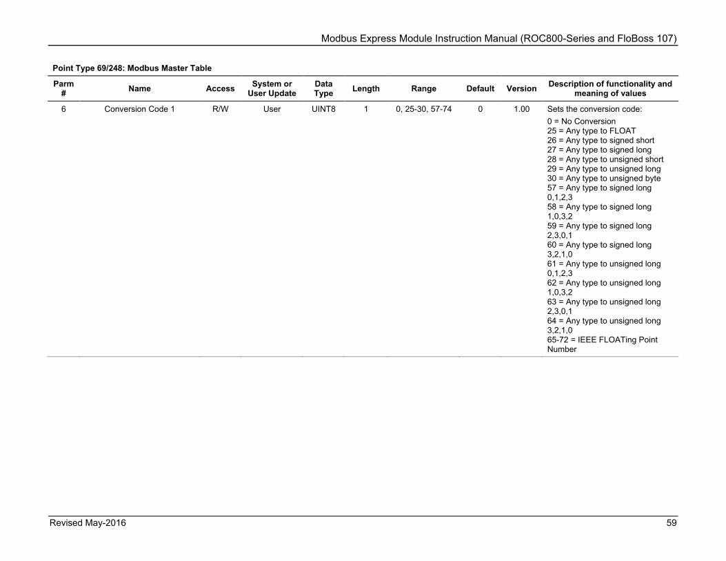
Modbus Express Module Instruction Manual (ROC800-Series and FloBoss 107)
Revised May-2016 59
Point Type 69/248: Modbus Master Table
Parm # Name Access System or
User Update Data Type Length Range Default Version Description of functionality and
meaning of values
6 Conversion Code 1 R/W User UINT8 1 0, 25-30, 57-74 0 1.00 Sets the conversion code: 0 = No Conversion 25 = Any type to FLOAT 26 = Any type to signed short 27 = Any type to signed long 28 = Any type to unsigned short 29 = Any type to unsigned long 30 = Any type to unsigned byte 57 = Any type to signed long 0,1,2,3 58 = Any type to signed long 1,0,3,2 59 = Any type to signed long 2,3,0,1 60 = Any type to signed long 3,2,1,0 61 = Any type to unsigned long 0,1,2,3 62 = Any type to unsigned long 1,0,3,2 63 = Any type to unsigned long 2,3,0,1 64 = Any type to unsigned long 3,2,1,0 65-72 = IEEE FLOATing Point Number

Modbus Express Module Instruction Manual (ROC800-Series and FloBoss 107)
60 Revised May-2016
Point Type 69/248: Modbus Master Table
Parm # Name Access System or
User Update Data Type Length Range Default Version Description of functionality and
meaning of values
7 Comm Status 1 R System UINT8 1 0-9, 128-131, 144-145
0 1.00 Shows the last poll status. 0 = Inactive 1 = Timeout Error 2 = Addr Check 3 = Function Code Error 4 = Num of Exp Bytes 5 = Rcv Slave Resp 6 = CRC/LRC Check 7 = CRC/LRC Check 8 = Valid Slave Resp 128 = Write Data Err 129 = Acc Dev Data 130 = Master Table Error 131 = Trans Timeout 144 = Tx/Rx Buff Ovr 145 = Invalid Func #
…
Note: Parameters 1-7 repeat up to 25 times, once for each Master Table entry.
169 Slave Address 25 R/W User UINT8 1 0-255 0 1.00 Sets the slave RTU address
170 Function Code 25 R/W User UINT8 1 0-6, 15-16 0 1.00 Sets the Modbus function code: 0 = Disabled 1 = Read logic coil status 2 = Read discrete input status 3 = Read output registers (holding) 4 = Read input registers 5 = Force single logic coil 6 = Preset single holding register 15 = Force multiple logic coils 16 = Preset multiple holding registers
171 Slave Register 25 R/W User UINT16 2 0-65535 0 1.00 Sets the device register
172 Master Register 25 R/W User UINT8 1 0-200 0 1.00 Sets the App module register
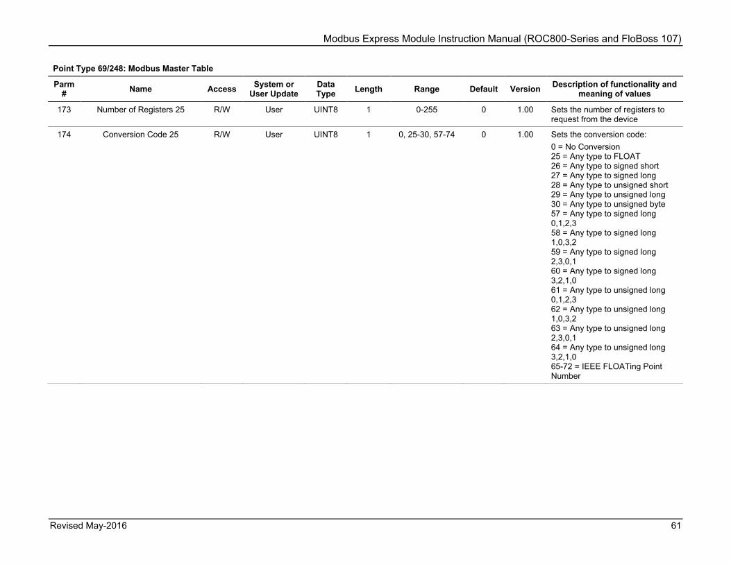
Modbus Express Module Instruction Manual (ROC800-Series and FloBoss 107)
Revised May-2016 61
Point Type 69/248: Modbus Master Table
Parm # Name Access System or
User Update Data Type Length Range Default Version Description of functionality and
meaning of values
173 Number of Registers 25 R/W User UINT8 1 0-255 0 1.00 Sets the number of registers to request from the device
174 Conversion Code 25 R/W User UINT8 1 0, 25-30, 57-74 0 1.00 Sets the conversion code: 0 = No Conversion 25 = Any type to FLOAT 26 = Any type to signed short 27 = Any type to signed long 28 = Any type to unsigned short 29 = Any type to unsigned long 30 = Any type to unsigned byte 57 = Any type to signed long 0,1,2,3 58 = Any type to signed long 1,0,3,2 59 = Any type to signed long 2,3,0,1 60 = Any type to signed long 3,2,1,0 61 = Any type to unsigned long 0,1,2,3 62 = Any type to unsigned long 1,0,3,2 63 = Any type to unsigned long 2,3,0,1 64 = Any type to unsigned long 3,2,1,0 65-72 = IEEE FLOATing Point Number

Modbus Express Module Instruction Manual (ROC800-Series and FloBoss 107)
62 Revised May-2016
Point Type 69/248: Modbus Master Table
Parm # Name Access System or
User Update Data Type Length Range Default Version Description of functionality and
meaning of values
175 Comm Status 25 R System UINT8 1 0-8, 128-131, 144-145
0 1.00 Shows the last poll status. 0 = Inactive 1 = Timeout Error 2 = Addr Check 3 = Function Code Error 4 = Num of Exp Bytes 5 = Rcv Slave Resp 6 = CRC/LRC Check 7 = CRC/LRC Check 8 = Valid Slave Resp 128 = Write Data Err 129 = Acc Dev Data 130 = Master Table Error 131 = Trans Timeout 144 = Tx/Rx Buff Ovr 145 = Invalid Func #

Modbus Express Module Instruction Manual (ROC800-Series and FloBoss 107)
Revised May-2016 63
5.3 Point Type 70/249: Modbus Registers Point type 70 (for FB107) or 249 (for ROC800) contains the registers (50 per logical) that the module uses to store data it reads from and writes to slave devices. This point type has four logicals.
Point Type 70/249: Modbus Registers
Parm # Name Access System or
User Update Data Type Length Range Default Versio
n Description of functionality and
meaning of values
0 Point Tag ID R/W User AC10 10 0x20 → 0x7E for each ASCII character
"Registers X", where X is the logical
1.00 Sets the point type description.
1 Register Value U32 1 R/W User UINT32 4 0-4294967295 0.0 1.00 Shows or sets the integer value for register number 1.
2 Register Value Float 1 R/W User FLOAT 4 Any valid IEEE floating point
0.0 1.00 Shows or sets the floating value for register number 1.
3 Register Tag 1 R/W User AC10 10 0x20 → 0x7E for each ASCII character
“” 1.00 Sets the description for register 1.
...
Note: Parameters 1-3 repeat up to 50 times, once for each Master Table entry.
148 Register Value U32 50
R/W User UINT32 4 0-4294967295 0.0 1.00 Sets the holding parameter for the value of register 50 if register is an integer (else 0).
149 Register Value FLOAT 50
R/W User FLOAT 4 Any valid IEEE floating point
0.0 1.00 Sets the holding parameter for the value of register 50 if register is floating point (else 0.0).
150 Register Tag 50 R/W User AC10 10 0x20 → 0x7E for each ASCII character
“” 1.00 Sets the description for register 50.

Modbus Express Module Instruction Manual (ROC800-Series and FloBoss 107)
64 Revised May-2016
5.4 Point Type 71/250: Modbus Expanded Registers Point type 71 (for FB107) or 250 (for ROC800) contains the expanded registers. This point type has twenty-five logicals.
Point Type 71/250: Modbus Expanded Registers
Parm # Name Access System or
User Update Data Type Length Range Default Versio
n Description of functionality and
meaning of values
0 Point Tag ID R/W User AC10 10 0x20 → 0x7E for each ASCII character
"Exp Reg X", where X is the logical
1.00 Shows or sets the Point Type description.
1 Expanded Register Type
R/W User UINT8 1 0-3 0 1.00 Shows or sets the I/O type for the expanded register: 0 = Disabled 1 = Floating Point 2 = Integer 3 = Digital
2 Parent Register R/W User UINT8 1 1-200 0 1.00 Shows or sets which register this expanded register maps to.
3 Float Value R System FLOAT 4 Any valid IEEE floating point
0.0 1.00 Shows the live value read from the register, in floating point form.
4 Float Manual Value R/W User FLOAT 4 Any valid IEEE floating point
0.0 1.00 Shows or sets the value for the register in floating point form.
5 Float Alarm Low Value
R/W User FLOAT 4 Any valid IEEE floating point
-10.0 1.00 Shows or sets the float alarm low value.
6 Float Alarm High Value
R/W User FLOAT 4 Any valid IEEE floating point
110.0 1.00 Shows or sets the float alarm high value.
7 Float Alarm Deadband Value
R/W User FLOAT 4 Any valid IEEE floating point
2.0 1.00 Shows or sets the float alarm deadband value.
8 Integer Value R/W User UINT32 4 0-4294967295 0 1.00 Shows the live value read from the register, in integer form.
9 Integer Manual Value R/W User UINT32 4 0-4294967295 0 1.00 Shows or sets the value for the register in integer form.
10 Integer Alarm Low Value
R/W User UINT32 4 0-4294967295 0 1.00 Shows or sets the integer alarm low value.
11 Integer Alarm High Value
R/W User UINT32 4 0-4294967295 110 1.00 Sets the integer alarm high value.

Modbus Express Module Instruction Manual (ROC800-Series and FloBoss 107)
Revised May-2016 65
Point Type 71/250: Modbus Expanded Registers
Parm # Name Access System or
User Update Data Type Length Range Default Versio
n Description of functionality and
meaning of values
12 Integer Alarm Deadband Value
R/W User UINT32 4 0-4294967295 2 1.00 Sets integer alarm deadband value.
13 Units R/W User AC10 10 0x20 – 0x7E for each ASCII character
“” 1.00 Sets string to indicate the units of the value.
14 Digital Status R System UINT8 1 0-1 0 1.00 Shows if the digital status is active or not. 0 = Off 1 = On
15 Digital Manual Status R/W User UINT8 1 0-1 0 1.00 Sets status for the register in digital form.
16 Alarm Mode R/W User UINT8 1 0-15 0 1.00 Configures the alarm mode: 0 = All alarms disabled Bit 0 = Floating point alarm enabled Bit 1 = Integer alarm enabled Bit 2-3 = Digital alarm bits Bit 2 (4) = Digital alarm on set Bit 3 (8) = Digital alarm on clear Bit 2 & 3 (12) = Digital alarm on change
17 Alarm Status R System U8 1 0-255 0 1.00 Shows the alarm status: 0 = No alarm Bit 0 = Low Alarm Bit 1 = Low Low Alarm (unused) Bit 2 = High Alarm Bit 3 = High High Alarm (unused) Bit 4 = Rate Alarm (unused) Bit 5 = Digital Alarm Bit 6 = Point Fail Alarm (unused) Bit 7 = Scanning Disabled (unused)

Modbus Express Module Instruction Manual (ROC800-Series and FloBoss 107)
66 Revised May-2016
Point Type 71/250: Modbus Expanded Registers
Parm # Name Access System or
User Update Data Type Length Range Default Versio
n Description of functionality and
meaning of values
18 Exp Reg UI Flags R/W User UINT8 1 0-255 0 1.00 Configures the user interface flags: Bit 0 = Float manual override Bit 1 = Float clipping Bit 2 = Int manual override Bit 3 = Int clipping Bit 4 = Digital override Bit 5 = Digital invert Bit 6 = unused Bit 7 = Show Int as bits

Modbus Express Module Instruction Manual (ROC800-Series and FloBoss 107)
Revised May-2016 67
[This page is intentionally left blank.]

Modbus Express Instruction Manual (ROC800-Series and FloBoss 107)
For customer service and technical support, visit www.EmersonProcess.com/Remote/Support.
Global Headquarters, North America, and Latin America:
Emerson Process Management Remote Automation Solutions 6005 Rogerdale Road Houston, TX 77072 U.S.A. T +1 281 879 2699 | F +1 281 988 4445 www.EmersonProcess.com/Remote
© 2014–2016 Remote Automation Solutions, a business unit of Emerson Process Management. All rights reserved. Remote Automation Solutions, a business unit of Emerson Process Management, shall not be liable for technical or editorial errors in this manual or omissions from this manual. REMOTE AUTOMATION SOLUTIONS MAKES NO WARRANTIES, EXPRESSED OR IMPLIED, INCLUDING THE IMPLIED WARRANTIES OF MERCHANTABILITY AND FITNESS FOR A PARTICULAR PURPOSE WITH RESPECT TO THIS MANUAL AND, IN NO EVENT SHALL REMOTE AUTOMATION SOLUTIONS BE LIABLE FOR ANY INCIDENTAL, PUNITIVE, SPECIAL OR CONSEQUENTIAL DAMAGES INCLUDING, BUT NOT LIMITED TO, LOSS OF PRODUCTION, LOSS OF PROFITS, LOSS OF REVENUE OR USE AND COSTS INCURRED INCLUDING WITHOUT LIMITATION FOR CAPITAL, FUEL AND POWER, AND CLAIMS OF THIRD PARTIES. Emerson Process Management Ltd, Remote Automation Solutions (UK), is a wholly owned subsidiary of Emerson Electric Co. doing business as Remote Automation Solutions, a business unit of Emerson Process Management. FloBoss, ROCLINK, ControlWave, Helicoid, FBxConnect, and OpenEnterprise are trademarks of Remote Automation Solutions. AMS, PlantWeb, and the PlantWeb logo are marks owned by one of the companies in the Emerson Process Management business unit of Emerson Electric Co. Emerson Process Management, Emerson and the Emerson logo are trademarks and service marks of the Emerson Electric Co. All other marks are property of their respective owners. The contents of this publication are presented for informational purposes only. While every effort has been made to ensure informational accuracy, they are not to be construed as warranties or guarantees, express or implied, regarding the products or services described herein or their use or applicability. Remote Automation Solutions reserves the right to modify or improve the designs or specifications of such products at any time without notice. All sales are governed by Remote Automation Solutions’ terms and conditions which are available upon request. Remote Automation Solutions does not assume responsibility for the selection, use or maintenance of any product. Responsibility for proper selection, use and maintenance of any Remote Automation Solutions product remains solely with the purchaser and end-user.
Europe: Emerson Process Management Remote Automation Solutions Unit 8, Waterfront Business Park Dudley Road, Brierley Hill Dudley UK DY5 1LX T +44 1384 487200 | F +44 1384 487258
Middle East/Africa: Emerson Process Management Remote Automation Solutions Emerson FZE P.O. Box 17033 Jebel Ali Free Zone – South 2 Dubai U.A.E. T +971 4 8118100 | F +971 4 8865465
Asia-Pacific: Emerson Process Management Remote Automation Solutions 1 Pandan Crescent Singapore 128461 T +65 6777 8211| F +65 6777 0947
Remote Automation Solutions