Embed Size (px)
Citation preview
ICSELECTRONICSICS
a division of Systems West Inc.
MODEL 8099Ethernet Modbus InterfaceInstruction Manual
8099
i
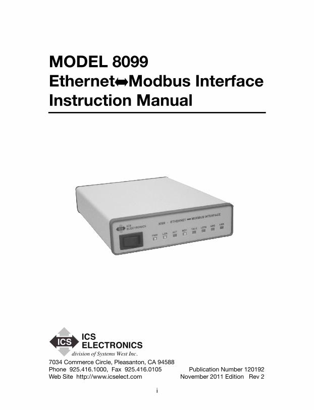
MODEL 8099 Ethernet Modbus Interface Instruction Manual
7034 Commerce Circle, Pleasanton, CA 94588 Phone 925.416.1000, Fax 925.416.0105 Publication Number 120192Web Site http://www.icselect.com November 2011 Edition Rev 2
ICSELECTRONICSICS
division of Systems West Inc.

ii
LIMITED WARRANTY
Within 12 months of delivery, ICS Electronics will repair or replace this product, at our option, if any part is found to be defective in materials or workmanship (labor is included). Return this product to ICS Electronics, or other designated repair station, freight prepaid, for prompt repair or replacement. Contact ICS for a return material authorization (RMA) number prior to returning the product for repair.
CERTIFICATION
ICS Electronics Corporation certifies that this product was carefully inspected and tested at the factory prior to shipment and was found to meet all requirements of the specification under which it was furnished.
EMI/RFI WARNING
This equipment generates, uses, and can radiate radio frequency energy and, if not installed and used in accordance with the instruction manual, may cause interference to radio communications. The Model 8099 has been tested and found to comply with the limits for a Class A computing device pursuant to Subpart J of Part 15 of the FCC Rules and to comply with the EEC Standards EEC Standards EN 61000-6-4:2001, EN 61000-6-2:2001, EN 55024:2003, and EN 55022:2003, which are designed to provide reasonable protection against such interference when operated in a com-mercial environment. Operation of this equipment in a residential area is likely to cause interference, in which case the user, at his own expense, will be required to take whatever measures may be required to correct the interference.
Certificate of Conformance reproduced in Figure 1-2.
TRADEMARKS
The following trademarks referred to in this manual are the property of the fol-lowing companies:
VEE is a trademark of Agilent, Palo Alto, CALabView is a Trademark of National istruments, Austin, TXICS and GPIB AnyWhere are trademarks of ICS Electronics, Pleasanton, CA
© 2010, 2011 ICS Electronics div of Systems West Inc.
i
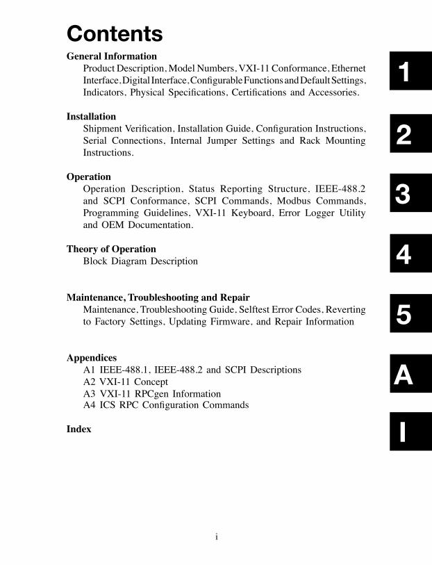
General Information Product Description, Model Numbers, VXI-11 Conformance, Ethernet
Interface, Digital Interface, Configurable Functions and Default Settings, Indicators, Physical Specifications, Certifications and Accessories.
Installation Shipment Verification, Installation Guide, Configuration Instructions,
Serial Connections, Internal Jumper Settings and Rack Mounting Instructions.
Operation Operation Description, Status Reporting Structure, IEEE-488.2
and SCPI Conformance, SCPI Commands, Modbus Commands, Programming Guidelines, VXI-11 Keyboard, Error Logger Utility and OEM Documentation.
Theory of Operation Block Diagram Description
Maintenance, Troubleshooting and Repair Maintenance, Troubleshooting Guide, Selftest Error Codes, Reverting
to Factory Settings, Updating Firmware, and Repair Information
Appendices A1 IEEE-488.1, IEEE-488.2 and SCPI Descriptions A2 VXI-11 Concept A3 VXI-11 RPCgen Information A4 ICS RPC Configuration Commands
Index
Contents
2
4
5
I
3
1
A
1-1
1
1
General Information1.1 INTRODUCTION
This section provides a description and specifications for ICS's Model 8099 Ethernet to Modbus Interface. All specifications and functional descriptions apply to all units unless otherwise stated.
1.2 DESCRIPTION
The Model 8099 Ethernet to Modbus Interface is a VXI-11.3 compliant in-terface that provides RS-232 and RS-422/RS485 serial interfaces to control Modbus devices using the Modbus RTU protocol. It lets the user send simple commands with ASCII values over a 10/100 Mbs TCP/IP network to control and query Modbus slave devices. The 8099 converts these simple commands into the Modbus RTU packet protocol and adds the CRC checksum to make a complete Modbus RTU packet. The Modbus RTU packets are sent serially over a RS-232 link to a single Modbus slave device or over a RS-485 network to one or multiple Modbus devices. Responses are checked and valid response data from a query is returned when the 8099 is next addressed to talk.
The 8099 contains a number of advanced features that increase its flexibility and simplifies their use in system applications. It is an IEEE-488.2 compatible interface with an expanded Status Reporting Structure that complies with the SCPI standard. SCPI commands are used to set the serial configuration, and to enable bits in the Status Reporting Structure to generate Service Requests. The user can also enter his own IDN message to personalize the unit as part of his assembly. The 8099 contains a webserver which allows the user to view and update the 8099's configuration settings. All settings are saved in nonvolatile memory.
1-2
1
The 8099 is VXI-11.3 compliant which makes it easily controllable from virtu-ally any computer with network access. One programming method is to make program calls to a VISA or SICL library which can communicate with VXI-11.3 instruments. LabView and VEE are graphical applications that can make VISA calls. SICL or VISA calls are recommended for Visual Basic, C and other program languages that can call any library. Another programming technique is to use the RPC protocol to communicate with the 8099. The RPC protocol makes it easy to control the 8099 from any LINUX/UNIX like environment. JAVA programming examples are available on SourceForge.
The module contains a single instrument personality, inst0. inst0 is an IEEE-488.2 compatible instrument and lets the user access the internal parser and execute modbus commands to control the slave Modbus devices. The Ethernet IP settings can be accessed by a web browser or by ICS's VXI-11 Configure utility program. A 'LAN Reset' button allows the user to return the card to its default IP settings at any time.
At power turn-on, the module's boot up and internal selftest process typically takes approximately 4 seconds. At the end of the selftest, the 8099 turns the RDY LED on if the test was successful. The LAN and ACT LEDs show the status of the network connection. The TALK, LSTN and SRQ LEDs show the module's current address status and if it has asserted a Service Request. The ERR LED is momentarily illuminated when the card senses a soft error condition or has a problem with a command that it received.
The 8099 conforms to the requirements for a LXI class C instrument per LXI Standard Rev 1.1 with the exception of no support for auto-IP configuration. The 8064 exceeds the LXI specification for a class C instrument because it is fully IEEE-488.2 compliant and specifies complete use of the VXI-11 protocol.
The Model 8099 is packaged in a small Minibox™ metal case that is less than 1U in height (1.6 inches) The front panel contains the power switch and LEDs which indicate the unit's status. The rear panel contains the Ethernet and serial connectors and a DC power jack. The 8099 accepts a wide range of DC volt-ages and is shipped with an adapter for the local power lines.
1-3
1
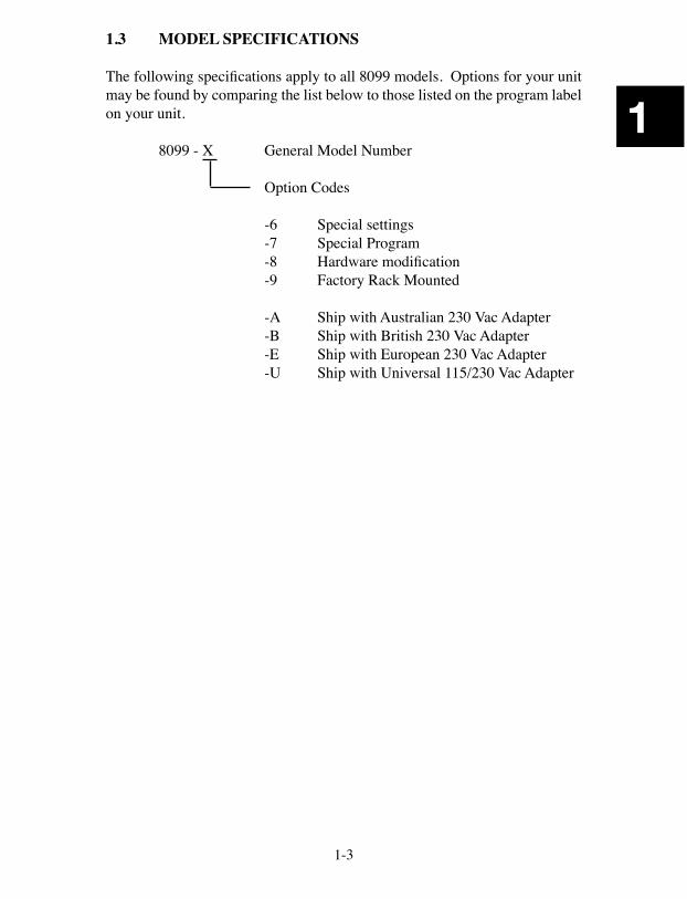
1.3 MODEL SPECIFICATIONS
The following specifications apply to all 8099 models. Options for your unit may be found by comparing the list below to those listed on the program label on your unit.
8099 - X General Model Number
Option Codes
-6 Special settings-7 Special Program-8 Hardware modification-9 Factory Rack Mounted
-A Ship with Australian 230 Vac Adapter-B Ship with British 230 Vac Adapter-E Ship with European 230 Vac Adapter-U Ship with Universal 115/230 Vac Adapter
1-4
1
1.4. VXI-11 CONFORMANCE
The 8099 is a TCP/IP-IEEE 488.2 Instrument and complies with the VXI-11.3 Specification.
1.4.1 RPC Protocol
The RPC protocol conforms to ONC RPC Version 2.
1.4.2 Sockets
The 8099's VXI-11 service supports 15 TCP/IP sockets for client communica-tion. The sockets are normally opened and closed by the clients. The unit will close the socket and release all resources if a broken connection is detected or when the link count goes to zero if Auto Disconnect is enabled.
There is a separate socket for UDP RPC Port Mapper communication.
1.4.3 Channels
Supports Core, Abort and Interrupt channels. Core and Abort channels each use a socket connection. Core channels support up to 64 device links and locks. A reverse Interrupt channel is a TCP/IP socket connection that does not count against the 15 client communication sockets limit.
1.4.4 Device Links and Locks
The 8099 support a maximum of 64 device links and 64 locks that can be used over multiple Core channels by one or more clients.
1.4.5 VXI-11 Interface Name
The 8064 has only one instrument personality and the default name is inst0. The name may be changed to any 8 character string.
1.4.6 VXI-11.3 Supported Functions
The 8099 supports all VXI-11.3 functions including:
create_link destroy_link create_intr_channel destroy_intr_channeldevice_lock device_unlock device_abortdevice_read device_write device_clear device_triggerdevice_remote device_local device_readstb create_intr_channeldevice_intr_SRQ device_enable_SRQ
1-5
1
1.5 ETHERNET INTERFACE
1.5.1 Type
IEEE-802.3 Compliant
1.5.2 Speed
Auto speed sensing, 10 Mbs with 10BaseT and 100 Mbs with 100BaseT
1.5.3 Network Address
Static: IP Address, Subnet Mask, and Gateway IPv4 values are user set from 0.0.0.0 to 255.255.255.255. Default values are listed in Table 1-3.
DHCP: Accepts IPv4 address from a DHCP Server.
1.5.4 KeepAlive Message
User enabled. Message sent if no activity for 120 minutes.
1.5.5 COMM Timeout
User set period, 0 to 232 seconds, to release socket resources if no activity.
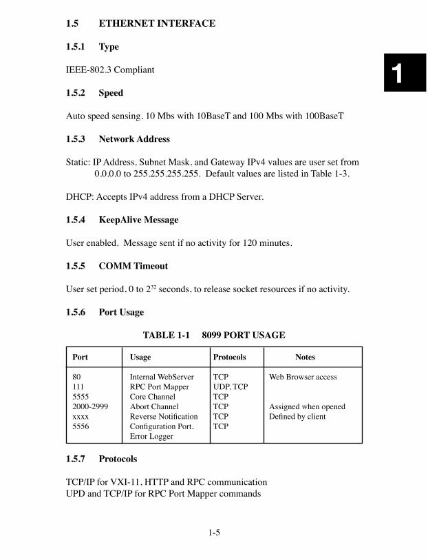
1.5.6 Port Usage
TABLE 1-1 8099 PORT USAGE
Port Usage Protocols Notes 80 Internal WebServer TCP Web Browser access111 RPC Port Mapper UDP, TCP5555 Core Channel TCP2000-2999 Abort Channel TCP Assigned when openedxxxx Reverse Notification TCP Defined by client5556 Configuration Port, TCP Error Logger
1.5.7 Protocols
TCP/IP for VXI-11, HTTP and RPC communicationUPD and TCP/IP for RPC Port Mapper commands
1-6
1
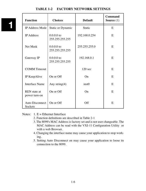
TABLE 1-2 FACTORY NETWORK SETTINGS
CommandFunction Choices Default Source (1)
IP Address Mode Static or Dynamic Static E
IP Address 0.0.0.0 to 192.168.0.254 E 255.255.255.255 Net Mask 0.0.0.0 to 255.255.255.0 E 255.255.255.255 Gateway IP 0.0.0.0 to 192.168.0.1 E 255.255.255.255
COMM Timeout 120 sec E
IP KeepAlive On or Off On E Interface Name Any string(4) inst0 E
REN state at On or Off On Epower turn-on
Auto Disconnect On or Off Off ESockets
Notes: 1. E = Ethernet Interface2. Function definitions are described in Table 2-13. The 8099's MAC Address is factory set and is not user changeable. The
MAC Address can be read with the VXI-11 Configuration Utility or with a web Browser.
4. Changing the interface name may cause your application to stop work-ing.
5. Setting Auto Disconnect on may cause your application to loose its connection to the 8099.
1-7
1
1.6 INTERNAL WEB SERVER
The internal WebServer provides HTML web pages to W3C compliant brows-ers.
1.6.1 HTML Pages
The standard HTML pages conform to HTML version 4.01 or XHTML version 1.0. The required pages are needed for correct WebServer operation. User can redefine the other page names. The WebServer serves the stored pages after substituting values for the variable placeholders. The standard 8099 pages are:
404.html 404 Error Page (required page)501.html 501 Error Page (required page)index.html Welcome Page (required page)config.html Configuration Pageconfirm.html Confirmation Pagereboot.html Reboot Page
1.6.3 Graphics
Image files with .jpg or .gif extensions are served as graphics. The standard graphic is:
ICS-Logo.gif ICS Logo
1.6.4 User Configurability
The user can replace the standard HTML pages and image files with modified pages or add additional pages and images to the card. User is responsible for assuring that any substituted HTML pages conform to HTML version 4.01 or XHTML version 1.0. Guidelines for modifying the pages are described in Application Bulletin AB80-5.
File types supported .html, .gif and .jpgNumber of files 32 maximumFile size 63 kbytes maximum for all files 32 kbytes maximum for a single fileFile name size 27 characters
1-8
1
1.7 SERIAL MODBUS INTERFACE
The 8099's asynchronous serial Modbus interface provides RS-232 single-ended and RS-485 (RS-422) differential signals with available internal termination network. Signals are selected by internal jumpers. The 8099 has a DB-25S connector on its rear panel. Signal pinouts conform to EIA RS-530 specifica-tion and are listed in Table 2-2.
1.7.1 Modbus RTU Message Format
Messages conform to the Modbus RTU format and include the device address, command, register number, data and CRC formatted as binary bytes. Supported Modbus commands are: 01, 02, 03, 04, 05, 06, 07, 08, and 16 for integer values and commands 03 and 16 for floating point 32-bit values.
Integer range 16 bits or 65,536 Floating point IEEE-754
1.7.2 Baud Rates
Parser selects closest rate to specified rate when a nonstandard rate entered. Standard rates are: 50, 110, 300, 600, 1200, 2400, 4800, 7200, 9600, 14400, 19200, 28800, 38400, 57600, 76800, and 115200 baud. 1.7.3 Data Character Formats:
Data bits 7 or 8 data bits per character Parity none, even or odd Stop bits 1 or 2 stop bits per character
1.7.4 RS-232 Specifications
All units have single-ended RS-232C drivers and receivers that are designed to operate with up to 50 feet of cable. Hardware handshaking is supported but not required.
Transmit +9 Vdc = Logic "0" or OnLevels -9 Vdc = Logic "1" or Off
Receive ±1.5 Vdc minimum, ±25 Vdc Maximum
Signals AA, AB, BA, BB, CA, CB, CD and CF
1-9
1
1.7.5 RS-422/RS-485 Specifications
The 8099 has balanced RS-485 line drivers and receivers that provide RS-422 and RS-485 compatible signals. The line drivers and receivers are designed to operate with up to 1200 meters of twisted-pair cable. The transmitter can be set for continuous on operation or it can be tristated when not transmitting. Hardware handshaking is ignored when RS485 is enabled.
Modes Transmitter always on (RS485 Mode Off) or tristated when not transmitting (RS485 mode On)
Transmit +5 Vdc differential for binary 0 or OnLevels -5 Vdc differential for binary 1 or Off
Receive ±0.2 Vdc minimum, ±25 Vdc maximum,Levels differential or single-ended input with other input line
biased at mid-range.
Signals SD, RD, RS, CS, RR and TR signal pairs (SD and RD only when RS485 mode On)
Termination Internal Pullup, termination and pulldown resistor Network network available on serial connector.
1-10
1
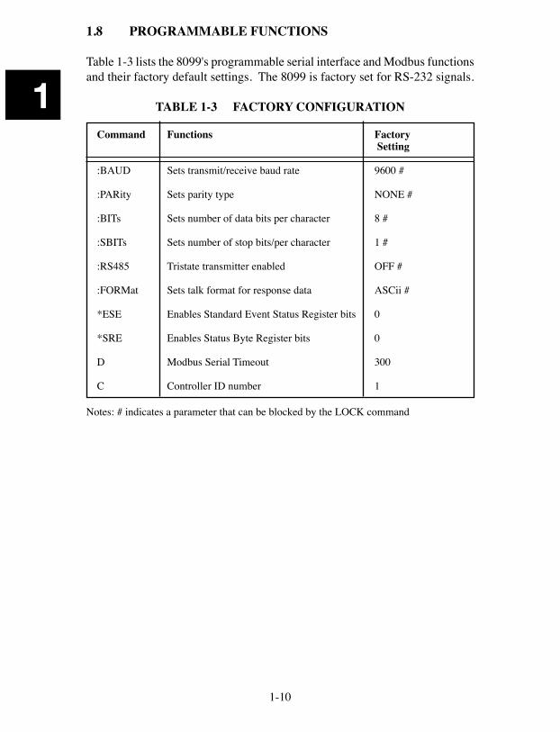
1.8 PROGRAMMABLE FUNCTIONS
Table 1-3 lists the 8099's programmable serial interface and Modbus functions and their factory default settings. The 8099 is factory set for RS-232 signals.
TABLE 1-3 FACTORY CONFIGURATION
Command Functions Factory Setting
:BAUD Sets transmit/receive baud rate 9600 #
:PARity Sets parity type NONE #
:BITs Sets number of data bits per character 8 #
:SBITs Sets number of stop bits/per character 1 #
:RS485 Tristate transmitter enabled OFF #
:FORMat Sets talk format for response data ASCii #
*ESE Enables Standard Event Status Register bits 0
*SRE Enables Status Byte Register bits 0
D Modbus Serial Timeout 300
C Controller ID number 1
Notes: # indicates a parameter that can be blocked by the LOCK command
1-11
1
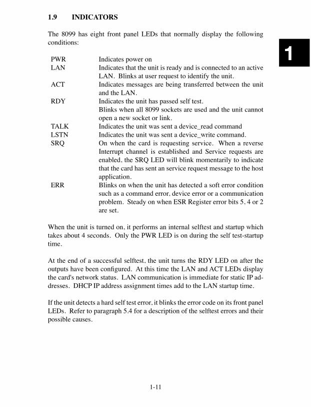
1.9 INDICATORS
The 8099 has eight front panel LEDs that normally display the following conditions:
PWR Indicates power onLAN Indicates that the unit is ready and is connected to an active
LAN. Blinks at user request to identify the unit.ACT Indicates messages are being transferred between the unit
and the LAN.RDY Indicates the unit has passed self test. Blinks when all 8099 sockets are used and the unit cannot
open a new socket or link.TALK Indicates the unit was sent a device_read commandLSTN Indicates the unit was sent a device_write command.SRQ On when the card is requesting service. When a reverse
Interrupt channel is established and Service requests are enabled, the SRQ LED will blink momentarily to indicate that the card has sent an service request message to the host application.
ERR Blinks on when the unit has detected a soft error condition such as a command error, device error or a communication problem. Steady on when ESR Register error bits 5, 4 or 2 are set.
When the unit is turned on, it performs an internal selftest and startup which takes about 4 seconds. Only the PWR LED is on during the self test-startup time.
At the end of a successful selftest, the unit turns the RDY LED on after the outputs have been configured. At this time the LAN and ACT LEDs display the card's network status. LAN communication is immediate for static IP ad-dresses. DHCP IP address assignment times add to the LAN startup time.
If the unit detects a hard self test error, it blinks the error code on its front panel LEDs. Refer to paragraph 5.4 for a description of the selftest errors and their possible causes.
1-12
1
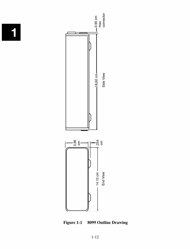
Figure 1-1 8099 Outline Drawing
18.9
2 cm
Side
Vie
w
14.1
5 cm
End
View
3.86
cm
.254
cm
0.95
cm
max
conn
ecto
r

1-13
1
1.10 PHYSICAL
Size 7.45" L x 5.57" W x 1.52" H (18.92 cm L x 14.15 cm W x 3.86 cm H) (See Figure 1-1)
Material PC Board - FR406 Flame resistant Fiberglass Components - RoHS compliant
Construction Lead Free
Weight 3 lbs (1.4 kg) including adapter
Temperature Operating -10 °C to +55 °C Storage -40 °C to +70 °C
Humidity 0-90% RH without condensation
Power 9 to 32 Vdc @ 3.5 VA Connectors Ethernet RJ-45
Serial Cinch DB-25S with lock studs
1-14
1
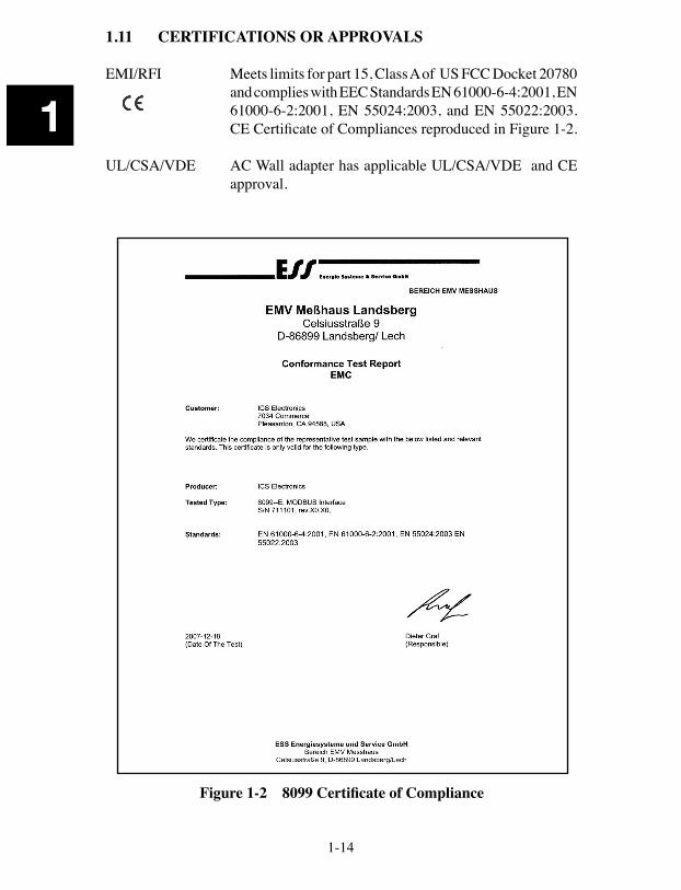
1.11 CERTIFICATIONS OR APPROVALS
EMI/RFI Meets limits for part 15, Class A of US FCC Docket 20780 and complies with EEC Standards EN 61000-6-4:2001, EN 61000-6-2:2001, EN 55024:2003, and EN 55022:2003. CE Certificate of Compliances reproduced in Figure 1-2.
UL/CSA/VDE AC Wall adapter has applicable UL/CSA/VDE and CE approval.
Figure 1-2 8099 Certificate of Compliance
1-15
1
1.12 INCLUDED ACCESSORIES
120192 8099 Instruction Manual 123038 Support CD-ROM with Configuration Program, Documentation, Sample Programs and Utilities. 895011 Ethernet Crossover Cable (5 feet long) A/R Power adapter with appropriate country plug
1.13 OPTIONAL ACCESSORIES
120192 8099 Instruction Manual 895011 Ethernet Crossover Cable (5 feet long) 114210 Single Small Minibox Rack Mount Kit 114211 Dual Small Minibox Rack Mount Kit 114227 Large/Small Minibox Rack Mounting Kit

1-16
1
This page intentionally left blank
2-1
2
2
Installation2.1 INTRODUCTION
This section provides the user with directions for shipment verification, for installing the module, for configuring the 8099’s Ethernet Interface for opera-tion on the network, and for connecting to its serial interface.
2.2 UNPACKING
When unpacking, check the unit for signs of shipping damage (damaged box, scratches, dents, etc.) If the unit is damaged or fails to meet specifications, notify ICS Electronics or your local sales representative immediately. Also, call the carrier immediately and retain the shipping carton and packing material for the carrier’s inspection. ICS will make arrangements for the unit to be repaired or replaced without waiting for the claim against the carrier to be settled.
2.3 SHIPMENT VERIFICATION
Take a moment to verify that the following items were included with your unit:
(1) Model 8099 Ethernet to Modbus Interface (1) AC Power Adapter (1) Instruction Manual (1) Support CD-ROM (1) Ethernet Crossover Cable
2-2
2
2.4 QUICK INSTALLATION GUIDE
The following steps should be used as to set up and use the 8099. New users should read Sections 2 and 3 before proceeding. 1. IMPORTANT: A new module must be configured with your network
settings before being connected to your network. Follow the direc-tions in Paragraph 2.5 to configure the module’s network parameters before connecting it to the general network.
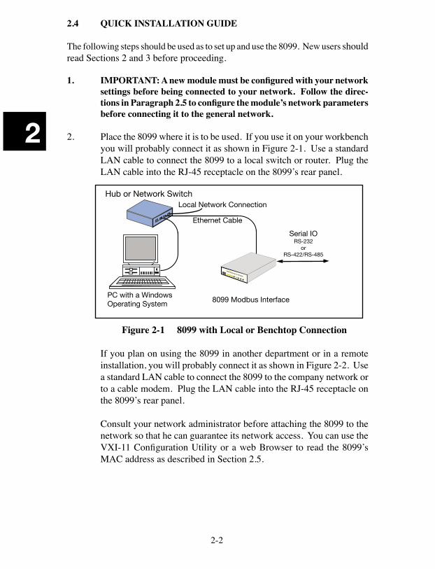
2. Place the 8099 where it is to be used. If you use it on your workbench you will probably connect it as shown in Figure 2-1. Use a standard LAN cable to connect the 8099 to a local switch or router. Plug the LAN cable into the RJ-45 receptacle on the 8099’s rear panel.
8099 Ethernet to Modbusl
Ethernet Cable
PC with a WindowsOperating System 8099 Modbus Interface
Hub or Network SwitchLocal Network Connection
Serial IORS-232
orRS-422/RS-485
Figure 2-1 8099 with Local or Benchtop Connection
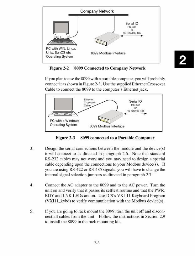
If you plan on using the 8099 in another department or in a remote installation, you will probably connect it as shown in Figure 2-2. Use a standard LAN cable to connect the 8099 to the company network or to a cable modem. Plug the LAN cable into the RJ-45 receptacle on the 8099’s rear panel.
Consult your network administrator before attaching the 8099 to the network so that he can guarantee its network access. You can use the VXI-11 Configuration Utility or a web Browser to read the 8099’s MAC address as described in Section 2.5.
2-3
2
Company Network
PC with WIN, Linux,Unix, SunOS etcOperating System
8099 Ethernet to Modbusl
8099 Modbus Interface
Serial IORS-232
orRS-422/RS-485
Figure 2-2 8099 Connected to Company Network If you plan to use the 8099 with a portable computer, you will probably
connect it as shown in Figure 2-3. Use the supplied Ethernet Crossover Cable to connect the 8099 to the computer’s Ethernet jack.
PC with a WindowsOperating System
EthernetCrossoverCable
8099 Ethernet to Modbusl
8099 Modbus Interface
Serial IORS-232
orRS-422/RS-485
Figure 2-3 8099 connected to a Portable Computer
3. Design the serial connections between the module and the device(s) it will connect to as directed in paragraph 2.6. Note that standard RS-232 cables may not work and you may need to design a special cable depending upon the connections to your Modbus device(s). If you are using RS-422 or RS-485 signals, you will have to change the internal signal selection jumpers as directed in paragraph 2.7.
4. Connect the AC adapter to the 8099 and to the AC power. Turn the unit on and verify that it passes its selftest routine and that the PWR, RDY and LNK LEDs are on. Use ICS’s VXI-11 Keyboard Program (VXI11_kybd) to verify communication with the Modbus device(s).
5. If you are going to rack mount the 8099, turn the unit off and discon-nect all cables from the unit. Follow the instructions in Section 2.9 to install the 8099 in the rack mounting kit.
2-4
2
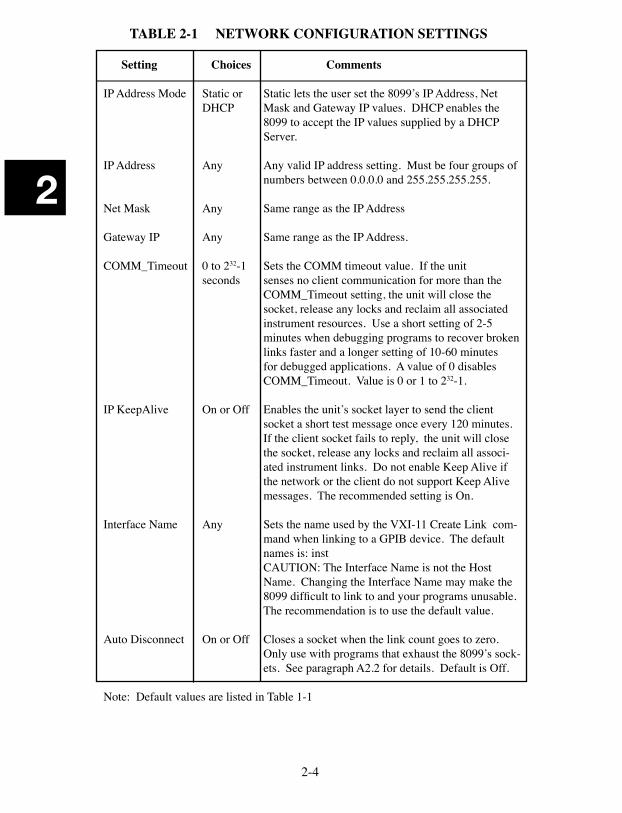
TABLE 2-1 NETWORK CONFIGURATION SETTINGS
Setting Choices Comments
IP Address Mode Static or Static lets the user set the 8099’s IP Address, Net DHCP Mask and Gateway IP values. DHCP enables the
8099 to accept the IP values supplied by a DHCP Server.
IP Address Any Any valid IP address setting. Must be four groups of numbers between 0.0.0.0 and 255.255.255.255.
Net Mask Any Same range as the IP Address
Gateway IP Any Same range as the IP Address.
COMM_Timeout 0 to 232-1 Sets the COMM timeout value. If the unit seconds senses no client communication for more than the
COMM_Timeout setting, the unit will close the socket, release any locks and reclaim all associated instrument resources. Use a short setting of 2-5 minutes when debugging programs to recover broken links faster and a longer setting of 10-60 minutes for debugged applications. A value of 0 disables COMM_Timeout. Value is 0 or 1 to 232-1.
IP KeepAlive On or Off Enables the unit’s socket layer to send the client socket a short test message once every 120 minutes. If the client socket fails to reply, the unit will close the socket, release any locks and reclaim all associ-ated instrument links. Do not enable Keep Alive if the network or the client do not support Keep Alive messages. The recommended setting is On.
Interface Name Any Sets the name used by the VXI-11 Create Link com-mand when linking to a GPIB device. The default names is: inst
CAUTION: The Interface Name is not the Host Name. Changing the Interface Name may make the 8099 difficult to link to and your programs unusable. The recommendation is to use the default value.
Auto Disconnect On or Off Closes a socket when the link count goes to zero. Only use with programs that exhaust the 8099’s sock-ets. See paragraph A2.2 for details. Default is Off.
Note: Default values are listed in Table 1-1
2-5
2
2.5 NETWORK AND SERIAL SETTINGS
This paragraph configures the 8099 for operation on your network and allows you to set the serial parameters. When shipped, the 8099’s network settings are configured as shown in Table 1-2. Review Tables 1-2 and 2-1 with your network administrator and decide on which settings, if any, that need to be changed. Table 2-1 provides detailed information about each network setting to help you with your decisions. The minimum change is to set the unit to a static IP address for your network so your PC can communicate with the card.
The network configuration can be changed and the card’s MAC Address can be read with a web browser (paragraph 2.5.1), by running ICS’s VXI-11 Con-figuration Utility on a WIN32 or WIN98 PC (paragraph 2.5.2), or with the RPC configuration commands listed in Appendix 3. Section 5.5 describes how to restore the factory settings.
The default serial settings are listed in Table 1-3. Compare them against the settings on your Modbus device. Adjust the serial settings on both units so that they match.
2.5.1 Web Browser Configuration Method
This method uses a standard browser such as Firefox, Internet Explorer or Netscape to view and change the current network settings.
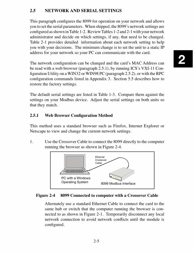
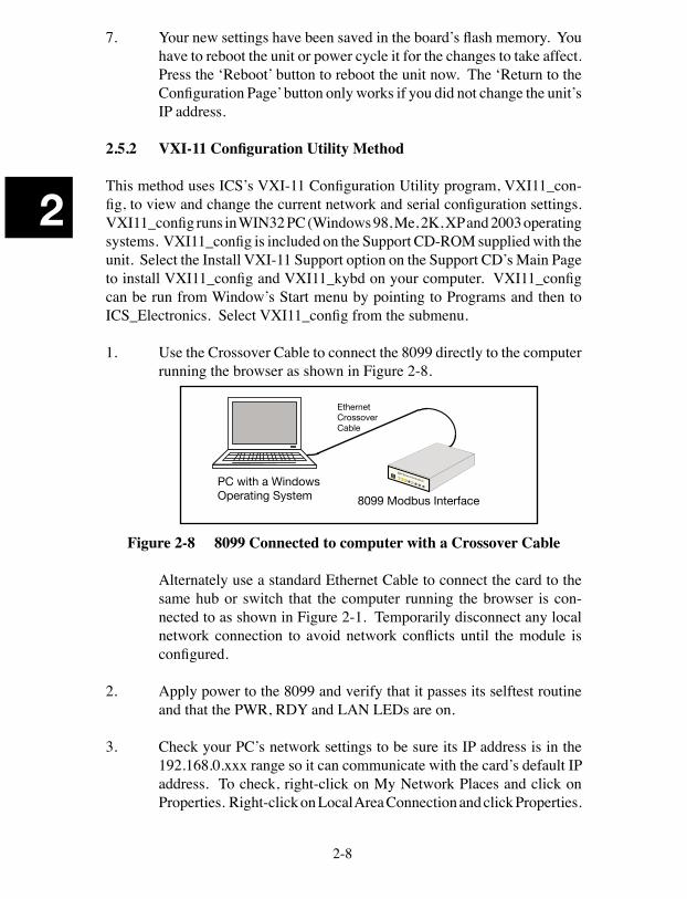
1. Use the Crossover Cable to connect the 8099 directly to the computer running the browser as shown in Figure 2-4.
PC with a WindowsOperating System
EthernetCrossoverCable
8099 Ethernet to Modbusl
8099 Modbus Interface
Figure 2-4 8099 Connected to computer with a Crossover Cable
Alternately use a standard Ethernet Cable to connect the card to the same hub or switch that the computer running the browser is con-nected to as shown in Figure 2-1. Temporarily disconnect any local network connection to avoid network conflicts until the module is configured.
2-6
2
2 Apply power to the 8099 and verify that it passes its selftest routine and that the PWR, RDY and LAN LEDs are on.
3 Check your computer’s network settings to be sure its IP address is in the 192.168.0.xxx range so it can communicate with the card’s de-fault IP address. If it is not, it must be set before proceeding. Use the values shown below. For Windows PCs, right-click on My Network Places and click on Properties. Right-click on Local Area Connection and click Properties. Highlight Internet Protocol (TCP/IP) and click Properties. If your PC’s IP address is in a different range, record the current settings and temporarily set the following network values:
Check ‘Use the following IP Address’ IP Address 192.168.0.2 Subnet mask 255.255.255.0
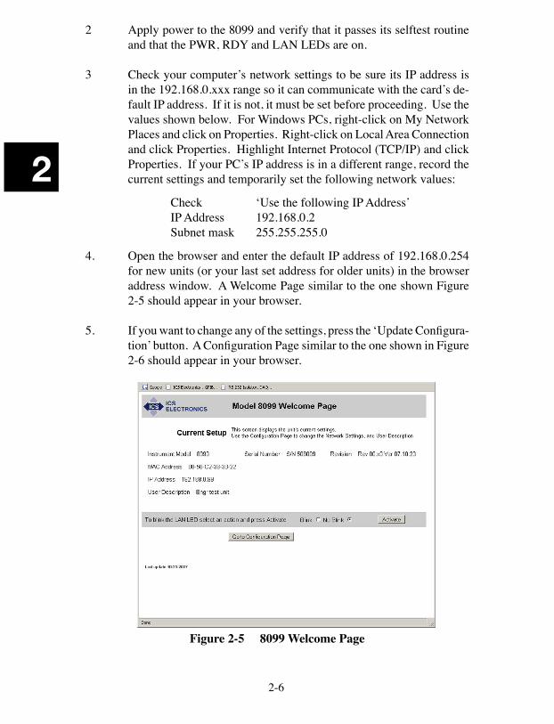
4. Open the browser and enter the default IP address of 192.168.0.254 for new units (or your last set address for older units) in the browser address window. A Welcome Page similar to the one shown Figure 2-5 should appear in your browser.
5. If you want to change any of the settings, press the ‘Update Configura-tion’ button. A Configuration Page similar to the one shown in Figure 2-6 should appear in your browser.
Figure 2-5 8099 Welcome Page
2-7
2
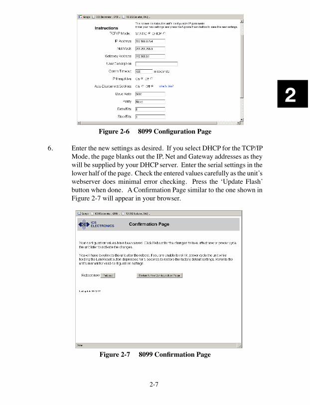
Figure 2-6 8099 Configuration Page
6. Enter the new settings as desired. If you select DHCP for the TCP/IP Mode, the page blanks out the IP, Net and Gateway addresses as they will be supplied by your DHCP server. Enter the serial settings in the lower half of the page. Check the entered values carefully as the unit’s webserver does minimal error checking. Press the ‘Update Flash’ button when done. A Confirmation Page similar to the one shown in Figure 2-7 will appear in your browser.
Figure 2-7 8099 Confirmation Page
2-8
2
7. Your new settings have been saved in the board’s flash memory. You have to reboot the unit or power cycle it for the changes to take affect. Press the ‘Reboot’ button to reboot the unit now. The ‘Return to the Configuration Page’ button only works if you did not change the unit’s IP address.
2.5.2 VXI-11 Configuration Utility Method
This method uses ICS’s VXI-11 Configuration Utility program, VXI11_con-fig, to view and change the current network and serial configuration settings. VXI11_config runs in WIN32 PC (Windows 98, Me, 2K, XP and 2003 operating systems. VXI11_config is included on the Support CD-ROM supplied with the unit. Select the Install VXI-11 Support option on the Support CD’s Main Page to install VXI11_config and VXI11_kybd on your computer. VXI11_config can be run from Window’s Start menu by pointing to Programs and then to ICS_Electronics. Select VXI11_config from the submenu.
1. Use the Crossover Cable to connect the 8099 directly to the computer running the browser as shown in Figure 2-8.
PC with a WindowsOperating System
EthernetCrossoverCable
8099 Ethernet to Modbusl
8099 Modbus Interface
Figure 2-8 8099 Connected to computer with a Crossover Cable
Alternately use a standard Ethernet Cable to connect the card to the same hub or switch that the computer running the browser is con-nected to as shown in Figure 2-1. Temporarily disconnect any local network connection to avoid network conflicts until the module is configured.
2. Apply power to the 8099 and verify that it passes its selftest routine and that the PWR, RDY and LAN LEDs are on.
3. Check your PC’s network settings to be sure its IP address is in the 192.168.0.xxx range so it can communicate with the card’s default IP address. To check, right-click on My Network Places and click on Properties. Right-click on Local Area Connection and click Properties.
2-9
2
Highlight Internet Protocol (TCP/IP) and click Properties. If your PC’s IP address is in a different range, record the current settings and temporarily set the following network values:
Check ‘Use the following IP Address’ IP Address 192.168.0.2 Subnet mask 255.255.255.0
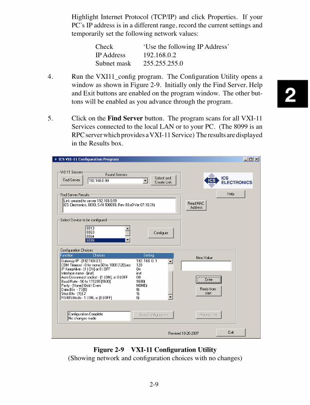
4. Run the VXI11_config program. The Configuration Utility opens a window as shown in Figure 2-9. Initially only the Find Server, Help and Exit buttons are enabled on the program window. The other but-tons will be enabled as you advance through the program.
5. Click on the Find Server button. The program scans for all VXI-11
Services connected to the local LAN or to your PC. (The 8099 is an RPC server which provides a VXI-11 Service) The results are displayed in the Results box.
Figure 2-9 VXI-11 Configuration Utility
(Showing network and configuration choices with no changes)
2-10
2
6. When the server(s) have been found, use the pulldown arrow in the Found Servers box to view the Found Server addresses. The card’s default address is 192.168.0.254. Highlight the card’s IP address and click the Create Link button. If the server is not found, you can enter the default IP address (192.168.0.254) or the host name in the Found Servers box. Click the Create Link button.
7. When the link has been created, device model number(s) will appear in the ‘Select Device to be Configured’ box. Highlight the desired model number and click the Configure button to start the configuration process.
8. The Configuration Choices box displays only one line with the first parameter to be changed and its current setting. If you like the current setting, click Enter to advance to the next parameter. If you want to change the setting, type a new value in the New Value box and click Enter. The program will send your setting to the card and read back the new setting. Repeat as needed to make another change or click Enter again to advance to the next parameter.
9. Repeat step 8 for each configuration parameter. Figure 2-9 shows the VXI-11 Configuration Utility after all parameters have been entered for a Model 8099. Click the Redo From Start button if you need to start over or if you want to change any of the prior settings
10. When done, the Save Configuration button is enabled if you changed any settings. Click the Save Configuration button to save the values in the card’s flash memory.
If you did not make any changes you can just exit the program.
11. The unit has to be power cycled or rebooted before the configuration changes take affect. Click the Reboot button to reboot the card and use the new settings.
12. Press the Exit button to quit the VXI11_config program.
13. If the IP address was changed to an address outside the 192.168.0.xxx range in step 3, your PC’s network settings will have to be changed to communicate with the card. Exit the VXI11_config program and restore the PC’s network settings.
2-11
2
2.6 SERIAL INTERFACE CONNECTIONS
2.6.1 8099 Serial Port
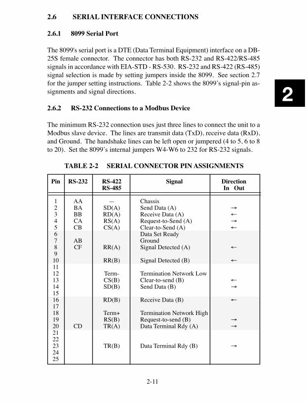
The 8099's serial port is a DTE (Data Terminal Equipment) interface on a DB-25S female connector. The connector has both RS-232 and RS-422/RS-485 signals in accordance with EIA-STD - RS-530. RS-232 and RS-422 (RS-485) signal selection is made by setting jumpers inside the 8099. See section 2.7 for the jumper setting instructions. Table 2-2 shows the 8099’s signal-pin as-signments and signal directions.
2.6.2 RS-232 Connections to a Modbus Device
The minimum RS-232 connection uses just three lines to connect the unit to a Modbus slave device. The lines are transmit data (TxD), receive data (RxD), and Ground. The handshake lines can be left open or jumpered (4 to 5, 6 to 8 to 20). Set the 8099’s internal jumpers W4-W6 to 232 for RS-232 signals.
RS-232
AABABBCACB
ABCF
CD
Pin
12345678910111213141516171819202122232425
TABLE 2-2 SERIAL CONNECTOR PIN ASSIGNMENTS
DirectionIn Out
→←→←
←
←
←→
←
→→
→
Signal
ChassisSend Data (A)Receive Data (A)Request-to-Send (A)Clear-to-Send (A)Data Set ReadyGroundSignal Detected (A)
Signal Detected (B)
Termination Network LowClear-to-send (B)Send Data (B)
Receive Data (B)
Termination Network HighRequest-to-send (B)Data Terminal Rdy (A)
Data Terminal Rdy (B)
RS-422RS-485
—SD(A)RD(A)RS(A)CS(A)
RR(A)
RR(B)
Term-CS(B)SD(B)
RD(B)
Term+RS(B)TR(A)
TR(B)
2-12
2
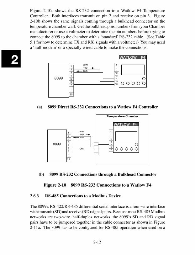
Figure 2-10a shows the RS-232 connection to a Watlow F4 Temperature Controller. Both interfaces transmit on pin 2 and receive on pin 3. Figure 2-10b shows the same signals coming through a bulkhead connector on the temperature chamber wall. Get the bulkhead pins numbers from your Chamber manufacturer or use a voltmeter to determine the pin numbers before trying to connect the 8099 to the chamber with s ‘standard’ RS-232 cable. (See Table 5.1 for how to determine TX and RX signals with a voltmeter) You may need a ‘null-modem’ or a specially wired cable to make the connections.
1234567..
25
8099
8099
TXD
RXD
1..
1213141516
WATLOW F4
(a) 8099 Direct RS-232 Connections to a Watlow F4 Controller
1234567..
25
8099
WATLOW F4
8099
TXD
RXD
1..
1213141516GND
Temperature Chamber
(b) 8099 RS-232 Connections through a Bulkhead Connector
Figure 2-10 8099 RS-232 Connections to a Watlow F4
2.6.3 RS-485 Connections to a Modbus Device
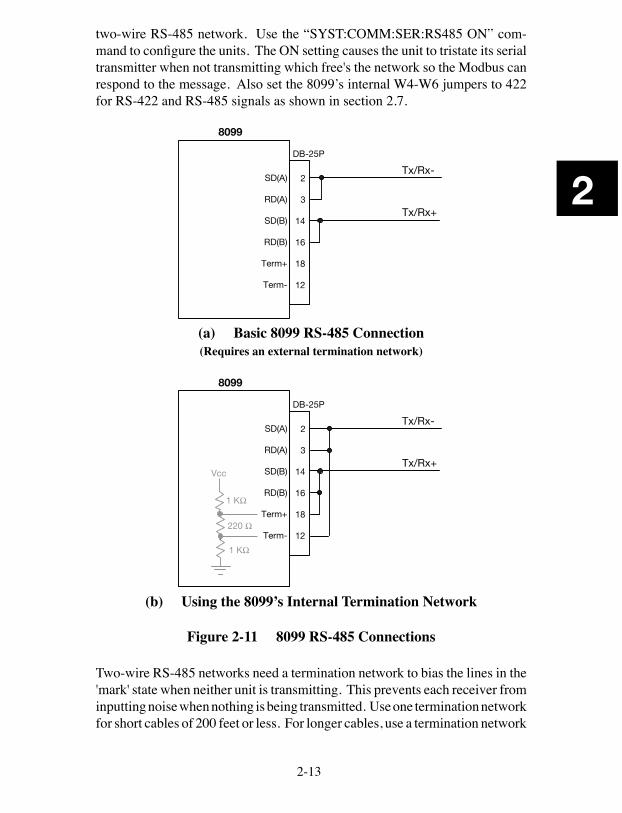
The 8099's RS-422/RS-485 differential serial interface is a four-wire interface with transmit (SD) and receive (RD) signal pairs. Because most RS-485 Modbus networks are two-wire, half-duplex networks, the 8099’s SD and RD signal pairs have to be jumpered together in the cable connector as shown in Figure 2-11a. The 8099 has to be configured for RS-485 operation when used on a
2-13
2
two-wire RS-485 network. Use the “SYST:COMM:SER:RS485 ON” com-mand to configure the units. The ON setting causes the unit to tristate its serial transmitter when not transmitting which free's the network so the Modbus can respond to the message. Also set the 8099’s internal W4-W6 jumpers to 422 for RS-422 and RS-485 signals as shown in section 2.7.
8099
DB-25P
2
3
14
16
18
12
SD(A)
RD(A)
SD(B)
RD(B)
Term+
Term-
Tx/Rx-
Tx/Rx+
(a) Basic 8099 RS-485 Connection(Requires an external termination network)
8099
DB-25P
2
3
14
16
18
12
1 K
Vcc
SD(A)
RD(A)
SD(B)
RD(B)
Term+
Term-
Tx/Rx-
Tx/Rx+
1 K
220
(b) Using the 8099’s Internal Termination Network
Figure 2-11 8099 RS-485 Connections
Two-wire RS-485 networks need a termination network to bias the lines in the 'mark' state when neither unit is transmitting. This prevents each receiver from inputting noise when nothing is being transmitted. Use one termination network for short cables of 200 feet or less. For longer cables, use a termination network
2-14
2
at each end of the cable. Figure 2-11b shows how to use the 8099’s internal termination network by adding two jumpers to the basic RS-485 connection.
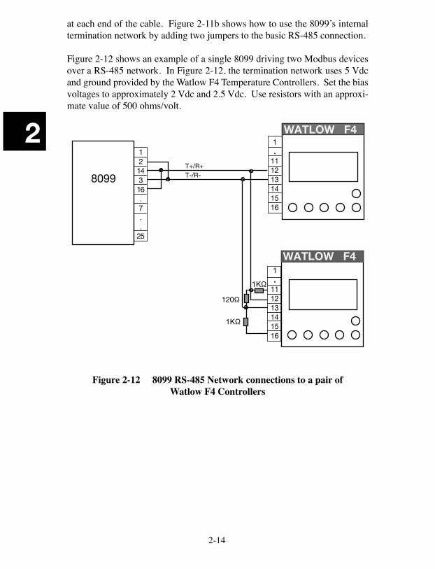
Figure 2-12 shows an example of a single 8099 driving two Modbus devices over a RS-485 network. In Figure 2-12, the termination network uses 5 Vdc and ground provided by the Watlow F4 Temperature Controllers. Set the bias voltages to approximately 2 Vdc and 2.5 Vdc. Use resistors with an approxi-mate value of 500 ohms/volt.
1214316.7..
25
8099
WATLOW F41.
111213141516
WATLOW F4
T+/R+T-/R-
1K
1K
120
1.
111213141516
Figure 2-12 8099 RS-485 Network connections to a pair of Watlow F4 Controllers
2-15
2
2.7 JUMPER SETTINGS
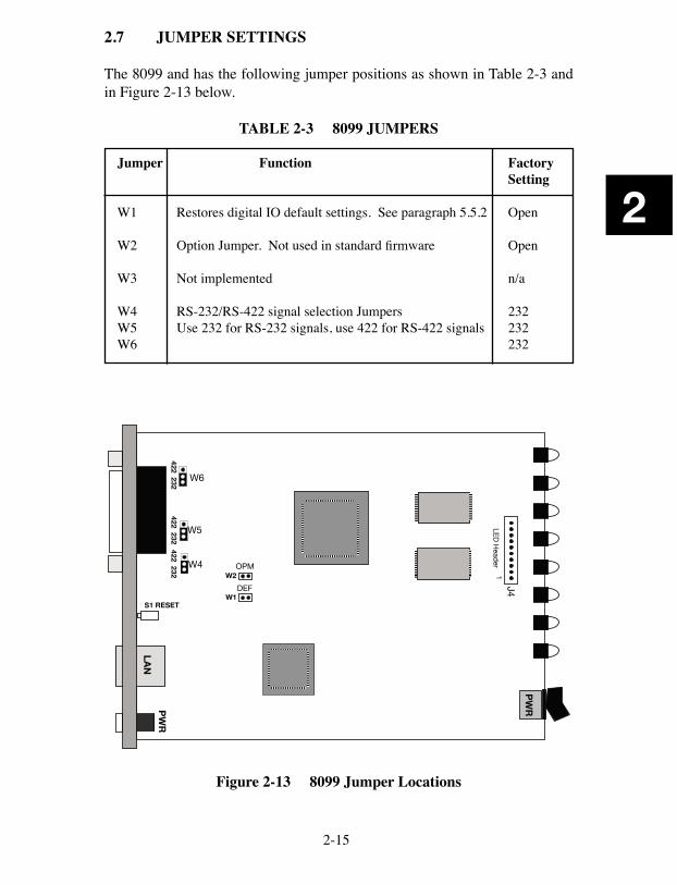
The 8099 and has the following jumper positions as shown in Table 2-3 and in Figure 2-13 below.
TABLE 2-3 8099 JUMPERS
Jumper Function Factory Setting
W1 Restores digital IO default settings. See paragraph 5.5.2 Open W2 Option Jumper. Not used in standard firmware Open
W3 Not implemented n/a W4 RS-232/RS-422 signal selection Jumpers 232W5 Use 232 for RS-232 signals, use 422 for RS-422 signals 232W6 232
UP
PW
R
UP
S1 RESETW1
W2
DEF
OPM
LAN
PW
R
J4LE
D H
eader
1
W6
W5
W4
422 232422 232
422 232
Figure 2-13 8099 Jumper Locations
2-16
2
2.8 8099 RACK MOUNTING INSTRUCTIONS
The Model 8099 is held in its rack mounting kit with a winged-'U' shaped bracket. Perform the following steps to install a 8099 in a rack mounting kit:
1. Hold the 8099 at a 30 degree nose down angle and place the front bezel through the rack mount kit from the rear of the kit. Push it forward through the opening until the rubber feet line up with the holes in the rack mounting kit. Push the unit down until it rests flat on the kit and the feet are in the four holes.
2. Repeat step 1 for a second unit if two units are being held in one rack mounting kit.
3. Align the unit(s) so the bezels are parallel with the front of the rack mount kit and protrude equally through the front panel of the rack mounting kit.
4. Set the bracket so its two holes line up with the holes in the rack mount-ing kit extrusion. Use the supplied 4-40 screws to hold the bracket to the extrusion. Do not overtighten.
5. Use the supplied 10-32 screws to bolt the rack mounting kit into the rack.
3-1
3
3
Programming Instructions3.1 INTRODUCTION
This section describes the operation of the 8099 Ethernet to Modbus Interface and how it is used to control slave Modbus devices. Because programming the 8099 over a network is different from traditional GPIB programming, a new user should read Appendixes A1 and A2 to familiarize himself with the VXI-11 concepts before programming the 8099. When the client application is linked to an 8099, the commands and operation of the Modbus Interface is substantially identical to that of ICS's 4899A GPIB to Modbus Interface.
3.2 OPERATION
3.2.1 VXI-11 Operation
The 8099 is a server in the client-server relationship and provides a VXI-11 service. The core channel link to interface inst0 in the 8099 is used for all commands and responses including 488.2, SCPI and Modbus commands. The 8099 does not have any additional interface personalities. The VISA Resource String is: TCPIP::ip::inst0::INSTR where ip is the ip address
3.2.2 Basic Modbus Operation
The 8099 is an VXI-11.3, IEEE-488.2 compatible device and responds to three types of commands: IEEE-488.2 Common Commands, SCPI Commands and a set of Modbus Commands to communicate with Modbus device(s). The IEEE-488.2 and SCPI commands are used to setup and configure the 8099's IEEE-488.2 Status Reporting Structure and its Serial parameters. Any com-mands that end in a ‘?’ are a query and the 8099 responds by outputting the response to the client the next time it receives a device_read message. (similar to a GPIB Talk address).
3-2
3
The 8099's communication path to the Modbus device is serial and requires that the user set the 8099 and the Modbus device to the same serial settings. Each Modbus device has its own address so that it can identify and respond to serial packets sent to its address. Although the typical Temperature Chamber or Process has only one Modbus Controller, the 8099 can drive multiple Modbus devices on an RS-485 network. The 'C' command is used to select the desired Modbus device. The 8099 remembers the Modbus device address until changed by a subsequent 'C' command or the 8099 is powered off or reset.
Modbus devices are register based devices and they are controlled by writing values to registers that control different functions i.e. temperature setpoint, alarm settings etc. Data is taken from Modbus devices by reading registers associated with those parameters i.e. temperature, humidity, etc. The 8099 can handle integer and floating point values. ICS has created a set of simple Modbus commands for reading, writing and communicating with Modbus devices. When one of these Modbus commands is sent to the 8099, the 8099 sends the appropriate Modbus RTU packet to the selected Modbus device. Modbus commands should not be mixed or concatenated with IEEE-488.2 or SCPI commands.
If the 8099's message packet is successfully received by the Modbus device, the Modbus device will generate a response packet that either confirms receipt of the message or that contains the requested data. The 8099 receives the response packet and validates the packet. If the response packet is a valid response to a read command, the returned data is held and will be transmitted to the cli-ent the next time the 8099 is sent a device_read request If the message is an acknowledgment message, there is no further action.
The 8099 expects to receive a response from the Modbus device within a preset time period or it declares a timeout error. The timeout period is programmable and is factory set to 300 milliseconds. It is better to set the timeout period to a larger than needed value to avoid unnecessary timeout errors.
If the message was not a valid message, or was an exception message, or was missing, then the 8099 sets the appropriate bit(s) in the Questionable Condi-tion Register, puts a decimal value in the Modbus Error register and sets bit 6 in the ESR Register. Both registers are part of the 8099’s Status Reporting Structure. See Figure 3-1. If the appropriate register enable bits are set true, then the Service Request bit will be set and generate a device_intr_srq message (SRQs). The device_intr_srq messages are sent to the Application over the reverse Interrupt channel. The user can then serial poll or query the Status Byte to determine the cause of the Service Request. Refer to Application Bulletin AB80-4 for information on handling RPC Interrupts.
3-3
3
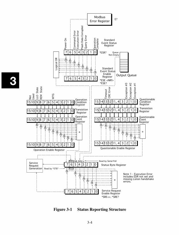
3.3 488.2 STATUS REPORTING STRUCTURE
The 8099 has the expanded IEEE-488.2 status reporting structure shown in Figure 3-1. The expanded status reporting structure conforms to the SCPI 1994.0 Specification and builds on the IEEE 488.2 Standard Status Report-ing Structure by adding the Questionable and Operation registers. The Event and Status registers are controlled and queried with the IEEE-488.2 common commands. The Status Byte Register may also be read by serial polling the card. The Questionable and Operation registers are controlled and queried with SCPI commands. The Modbus Error register is read and cleared with the Modbus E? command.
Instead of asserting the GPIB SRQ line, VXI-11.3 Instruments generate a Ser-vice Request message, device_intr_SRQ, when the RQS bit in the Status Byte Register becomes true. Service Requests (SRQs) are sent through the Interrupt Channel (if one has been setup) to alert the client that an event has occurred and/or that the device needs service. SRQ generation is a multilevel function and is determined by the occurrence of an event that has its corresponding enable bit set to '1'. The outputs from the event registers are summarized in separate bits in the Status Byte Register. The Event registers and the Output Queue are cleared when read or by the *CLS command.
3.3.1 Event Registers
An event register captures 0 to 1 transitions in its associated condition reg-ister or in the standard event register. An event bit becomes TRUE (1) when the associated condition bit makes a logical 0 to 1 transition. Once an event bit is set it is held until the event register is read or cleared with the *CLS command.
Each event register contains eight or sixteen bits. When the register is read, its response is a decimal number that is the sum of the binary bit weights of the bits that are logical 1s.
e.g., 23 decimal = 0001 0111 or 0000 0000 0001 0111 binary
Each event register bit has a corresponding enable bit. The enabling bits are ANDed with the state of the event bits to create the summary condition in the Status Byte Register. Unwanted conditions can be blocked from generating SRQs by setting their corresponding enabling bit to a '0'. The enabling bits are set by writing the value equal to the sum of all of the desired logic 1 bits to the enabling register. The value is normally decimal but can be expressed in HEX, OCTAL or BINARY by prefixing the number with a #H, #O or #B.
3-4
3
Figure 3-1 Status Reporting Structure
��������������������
��������
��������������
������������������������������������������
������
����
�����
��������������������
��������������
���������������
� ��
��
��
�
������������������������������
����������������������
�������������������������
��
��
�
��
�
��������������������������
���
����
��������������������������������������������������
�
���������������������
���
�������������������������
����������������������������
��
� ��
��
�
�����������������������������
�
�������������������
�
�����������������������������������
����������������������
���
�
��������������
�����������������������������
����������������������������� �������������������������������������������
��� ���
��������������������
�
��
��
��
�
���������������������������������������������������������������������������������
������������������������
�������
�
������
�������
���
������� �
���
�����
���
������
Flas
h D
ata
Cor
rupt
ed
����������
������
����
��������������������������������������������������
��������������������������������������������������
��������������������������������������������������
��
����
�����������
��������������������
�����
����
�������
����
������� �
����
������� �
����
��������
�����������������������������������
�����������������������������������
�����������������������������������
��
3-5
3
3.3.2 Event Status Register
The Event Status Register reports events that are common to all 488.2 devices. This includes events such as selftest errors, command errors, execution errors, power on and operation complete. The Power-on event occurs at power turn-on and can be used to signal a power off-on occurrence. The Modbus Error is included in the Event Status Register. Bit 6 is set when the Modbus Error Register is loaded with an error value. The 488.2 Operation Complete event has no meaning for the 8099.
TABLE 3-1 ESR BIT DEFINITIONS
Bit Event Description
7 PON The Power-on event occurs at power turn-on and can be used to signal a power off-on occurrence.
6 Modbus Modbus Error detected. Reading the Modbus Errror Register clears Error this bit.5 Cmd Command Error4. Exc Execution Error includes EDR not set and missing listen hand-
shake.3 Flash Flash data corrupted.2 Query Query error, data not read or read attempt with no data.1 EDR#2 External Data Ready Flip-flop #2 0 OPC Operation Complete has no meaning in the 80x3s.
The Event Status Register is read with the *ESR? query and cleared with the *CLS command. Use the *ESE commands to set the Event Status Enable Register as shown in the following example:
*ESE 60 'enables error bits 2 through 5 for errors*ESE 124 'enables error bits 2 through 5 and the EDR bit*ESE? 'queries the enabling register setting
3.3.3 Modbus Error Register
The Modbus Error Register reports a decimal value of the last error detected with the Modbus message transmission or reported back from the Modbus slave device. This register is cleared when read by the Modbus E? command. The *CLS and *RST commands have no affect on this register. Refer to Table 3-5 for the Modbus Error Register values. The following commands will generate a Service Request when a Modbus error occurs:
3-6
3
*ESE 64 ‘enables ESR bits 6 *SRE 32 ‘enables StatusByte bit 5
*ESR? ‘reads ESR Register bits E? ‘reads Modbus Error Register
3.3.4 Questionable Registers and Digital Inputs
The Questionable Registers lets the user read bits that report Modbus CRC errors, Exception message types or a timeout (no response message received). Bit alignments are shown in Figure 3-1. The Questionable Transition Register filters the inputs and passes only the enabled state changes to the Questionable Event Register. The Questionable Event Register bits becomes true (1) when the positive transition bit is enabled and the associated condition register bit makes a 0 to 1 transition. When both transitions are selected for the same bit, the corresponding Questionable Event Register bit sets whenever the digital input changes state. The Questionable Event Register is cleared when it is read.
The Questionable Registers are queried with the SCPI STATUS branch com-mands.
The 8099 can be set to monitor the bits in the Questionable Register and gener-ate a Service Request (SRQ) when they change state. The following example sets the Questionable Event register to monitor the CRC and Timeout bits by capturing a positive transition on bits 12 and 13. The decimal value for bit 12 is 4096 and the decimal value for bit 13 is 8192.
STAT:QUES:PTR 12298 ‘enables bits 12 and 13 to set on a positive transition
Because summing large decimal values is confusing, it is better to use HEX values that are easier to write. i.e.
STAT:QUES:PTR #h3000 ‘same as 12298 decimal
The Questionable Enable Register enables set Event bits to be included in the summary output to the Status Byte Register. The following example enables bits 12 and 13:
STAT:QUES:ENAB #h3000 ‘enables Event bits 12 and 13
Note that the Questionable Event Register has to be cleared after an Service Request is generated either by reading the register or with the *CLS command.
3-7
3
If the register is not cleared, the event bits will remain set and they will not generate another Service Request when the input again goes true.
STAT:QUES:COND? ‘reads the questionable inputs
3.3.4 Operation Registers
The 488.2 Operation Registers lets the user read device specific status condi-tions and detect any changes in the device’s status. The Operation Registers are similar to the Questionable Registers described in paragraph 3.3.3. In the 8099, the Operation Condition Register only reports the Local Lockout and Remote interface states. The following commands demonstrate some possibili-ties of the Operation Registers:
STAT:OPER:COND? ‘quires the Operation Condition Register
3.3.5 Output Queue
The Output Queue is used to output IEEE 488.2 and SCPI responses back to the client. The Output Queue reports a ‘1’ in bit 4 of the Status Byte Register when it contains a message(s) to be read by the bus controller. Reading the contents of the Output Queue clears its summary bit. The Output Queue is read by sending the 8099 a device_read message. If the Output Queue is not read before sending another query, its contents will be lost and an error reported.
Good programming technique is to follow each query by reading the result. Testing the Output Queue's summary bit before addressing the device to talk can confuse the unit and lead to erroneous results. Do not use the Output Queue's summary bit to determine when to read a response.
3.3.6 Status Byte Register
The 8099 generates a Service Request (SRQ) whenever any of the enabled bits in the Status Byte Register become true and the 8099 is not processing a device_read message. The Status Byte Register may be read with the de-vice_readstb function or with the *STB? query. The device_readstb function resets the RQS bit; the *STB? query does not change the bit. The Status Byte Register is enabled by setting the corresponding bits in the Service Request Enable Register with the *SRE command. e.g.
*SRE 160 ‘Sets the SRE Register to 1010 0000 which enables just the Event Status and Questionable summary bits to generate SRQs.
3-8
3
3.3.7 Saving the Enable and Transition Register Values
When the PSC flag is set, the Enable and Transition Register values are cleared at power turn-on. The registers can only be saved and recalled at power turn-on by disabling the PSC flag. The *SAV command does not save these registers. Use the *PSC 0 command to disable the PSC flag and save the current Enable and Transition register values as shown in the example. e.g.
STAT:OPER:ENAB 1 'enables Status A bitSTAT:OPER:NTR 1 'enables negative transition*PSC 0; ESE 192; SRE 32 'saves Power-on and EDR bits and current registers values as the new power on settings.
The enable and transition register setting commands must be on the same line or set prior to the *PSC 0 command to be saved. A later *PSC 1 command sets the PSC flag which will cause the registers to be cleared at the next power turn-on.
3.3.8 488.2 Differences from 488.1 Devices
The IEEE 488.1 Device Clear command does not reset the digital outputs as would be expected of a 488.1 device. To reset the digital outputs, use the *RST (Reset) or *RCL 0 command.
3-9
3
TABLE 3-2 IEEE-488.2 COMMON COMMANDS
COMMAND NAME DESCRIPTION
Clears all event registers summarized in the status byte, except for "Message Avail-able," which is cleared only if *CLS is the first message in the command line.
Sets "Event Status Enable Register" to <value>. <value> is an integer between 0 and 255, whose binary equivalent cor-responds to the state (1 or 0) of bits in the register. If <value> is not between 0 and 255, an Execution Error is generated.
EXAMPLE: decimal 16 converts to binary 00010000 which sets bit 4 to a logical 1.
8099 returns the <value> of the "Event Status Enable Register" set by the *ESE command. <value> is an integer whose binary equivalent corresponds to the state (1 or 0) of bits in the register.
8099 returns the <value> of the "Event Status Register" and then clears it. <value> is an integer whose binary equivalent corresponds to the state (1 or 0) of bits in the register.
Clear Status
Event Status En-able
Event StatusEnable Query
Event StatusRegister Query
* CLS
*ESE <value>
*ESE?
*ESR?
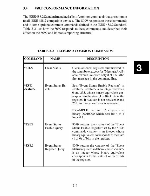
3.4 488.2 CONFORMANCE INFORMATION
The IEEE 488.2 Standard mandated a list of common commands that are common to all IEEE 488.2 compatible devices. The 8099 responds to these commands and to some optional common commands defined in the IEEE-488.2 Standard. Table 3-2 lists how the 8099 responds to these commands and describes their effect on the 8099 and its status reporting structure.
3-10
3
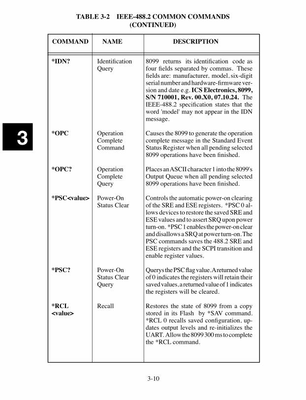
TABLE 3-2 IEEE-488.2 COMMON COMMANDS (CONTINUED)
COMMAND NAME DESCRIPTION
*IDN?
*OPC
*OPC?
*PSC<value>
*PSC?
*RCL <value>
Identification Query
Operation CompleteCommand
Operation CompleteQuery
Power-OnStatus Clear
Power-OnStatus Clear Query
Recall
8099 returns its identification code as four fields separated by commas. These fields are: manufacturer, model, six-digit serial number and hardware-firmware ver-sion and date e.g. ICS Electronics, 8099, S/N 710001, Rev. 00.X0, 07.10.24. The IEEE-488.2 specification states that the word 'model' may not appear in the IDN message.
Causes the 8099 to generate the operation complete message in the Standard Event Status Register when all pending selected 8099 operations have been finished.
Places an ASCII character 1 into the 8099's Output Queue when all pending selected 8099 operations have been finished.
Controls the automatic power-on clearing of the SRE and ESE registers. *PSC 0 al-lows devices to restore the saved SRE and ESE values and to assert SRQ upon power turn-on. *PSC 1 enables the power-on clear and disallows a SRQ at power turn-on. The PSC commands saves the 488.2 SRE and ESE registers and the SCPI transition and enable register values. Querys the PSC flag value. A returned value of 0 indicates the registers will retain their saved values, a returned value of 1 indicates the registers will be cleared.
Restores the state of 8099 from a copy stored in its Flash by *SAV command. *RCL 0 recalls saved configuration, up-dates output levels and re-initializes the UART. Allow the 8099 300 ms to complete the *RCL command.
3-11
3
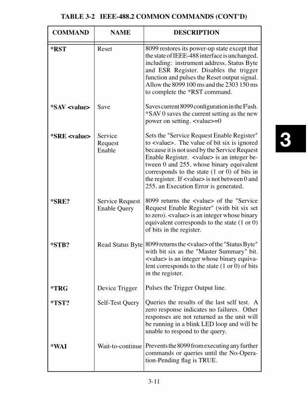
TABLE 3-2 IEEE-488.2 COMMON COMMANDS (CONT'D)
COMMAND NAME DESCRIPTION
Reset
Save
Service RequestEnable
Service RequestEnable Query
Read Status Byte
Device Trigger
Self-Test Query
Wait-to-continue
8099 restores its power-up state except that the state of IEEE-488 interface is unchanged, including: instrument address, Status Byte and ESR Register. Disables the trigger function and pulses the Reset output signal. Allow the 8099 100 ms and the 2303 150 ms to complete the *RST command.
Saves current 8099 configuration in the Flash. *SAV 0 saves the current setting as the new power on setting. <value>=0
Sets the "Service Request Enable Register" to <value>. The value of bit six is ignored because it is not used by the Service Request Enable Register. <value> is an integer be-tween 0 and 255, whose binary equivalent corresponds to the state (1 or 0) of bits in the register. If <value> is not between 0 and 255, an Execution Error is generated.
8099 returns the <value> of the "Service Request Enable Register" (with bit six set to zero). <value> is an integer whose binary equivalent corresponds to the state (1 or 0) of bits in the register.
8099 returns the <value> of the "Status Byte" with bit six as the "Master Summary" bit. <value> is an integer whose binary equiva-lent corresponds to the state (1 or 0) of bits in the register.
Pulses the Trigger Output line.
Queries the results of the last self test. A zero response indicates no failures. Other responses are not returned as the unit will be running in a blink LED loop and will be unable to respond to the query.
Prevents the 8099 from executing any further commands or queries until the No-Opera-tion-Pending flag is TRUE.
*RST
*SAV <value>
*SRE <value>
*SRE?
*STB?
*TRG
*TST?
*WAI
3-12
3
3.5 SCPI CONFORMANCE INFORMATION
The 8099 accepts SCPI commands and command extensions to configure its Serial interface and to set the data formats. The SCPI commands conform to SCPI Standard 1994.0 and provide an industry standard, self-documenting form of code that makes it easy for the programmer to maintain the applica-tion program.
Table 3-3 shows the 8099’s SCPI command tree. The command tree uses portions of the SCPI SYSTEM, STATUS, FORMAT, INITIATE, ABORT and CALIBRATE subsystems. The 8099 follows SCPI’s hierarchal ‘tree like’ structure which starts with a root keyword and branches out to the final action keyword. Each command can be used as a query except where noted. The SCPI commands are not case sensitive. The portion of the command shown in capitals denotes the abbreviated form of the keyword. Either the abbreviated or whole keyword may be used when entering a complete command. Bracketed keywords are optional and may be omitted.
STATus:QUEStionable? is the same as STAT:QUES:EVEN? or also asstat:ques?
There must be a space between the SCPI command and the parameter or chan-nel list. Ending a SCPI command with a question mark '?' makes it a query and allows you to read back the command setting or current value. All queries should be followed by reading their response to avoid data loss.
SYST:COMM:SER:BAUD 9600 SCPI commandSYST:COMM:SER:BAUD? query form of the command
Table 3-4 lists the SCPI keywords and describes their functions in detail. Keywords other than those listed in the table or locked keywords will have no effect on the 8099’s operation and a command error will be reported. Refer to Appendix A-1 for additional information about SCPI commands.
3-13
3
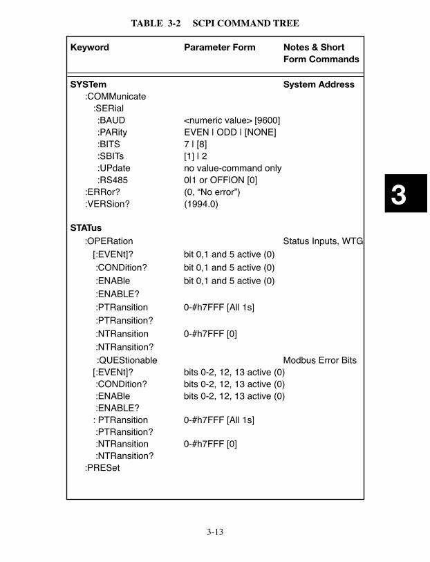
TABLE 3-2 SCPI COMMAND TREE
Keyword Parameter Form Notes & Short Form Commands
SYSTem System Address :COMMunicate :SERial :BAUD <numeric value> [9600] :PARity EVEN | ODD | [NONE] :BITS 7 | [8] :SBITs [1] | 2 :UPdate no value-command only :RS485 0|1 or OFF|ON [0] :ERRor? (0, “No error”) :VERSion? (1994.0)
STATus :OPERation Status Inputs, WTG [:EVENt]? bit 0,1 and 5 active (0) :CONDition? bit 0,1 and 5 active (0) :ENABle bit 0,1 and 5 active (0) :ENABLE? :PTRansition 0-#h7FFF [All 1s] :PTRansition? :NTRansition 0-#h7FFF [0] :NTRansition? :QUEStionable Modbus Error Bits [:EVENt]? bits 0-2, 12, 13 active (0) :CONDition? bits 0-2, 12, 13 active (0) :ENABle bits 0-2, 12, 13 active (0) :ENABLE? : PTRansition 0-#h7FFF [All 1s] :PTRansition? :NTRansition 0-#h7FFF [0] :NTRansition? :PRESet
3-14
3
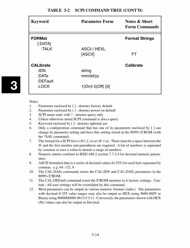
TABLE 3-2 SCPI COMMAND TREE (CONT'D)
Keyword Parameter Form Notes & Short Form Commands
FORMat Format Strings [:DATA] :TALK ASCii | HEXL [ASCII] FT
CALibrate Calibrate :IDN string :DATe mm/dd/yy :DEFault :LOCK 1(On)| 0(Off) [0]
Notes:1. Parameter enclosed by [ ] - denotes factory default2. Parameter enclosed by ( ) - denotes power on default3. SCPI name ends with ? - denotes query only4. Unless otherwise noted SCPI command is also a query5. Keyword enclosed by [ ] - denotes optional use6. Only a configuration command that has one of its parameters enclosed by [ ] can
change its parameter setting and have this setting stored in the 8099's E2ROM (with the *SAV command).
7. The format for a SCPI list is (@1,2, n) or (@ 1:n). There must be a space between the @ and the first number and parenthesis are required. A list of numbers is separated by commas or uses a colon to denote a range of numbers.
8. Numeric entries conform to IEEE-488.2 section 7.7.2.4 for decimal numeric param-eters.
9. ASCII formatted data is a series of decimal values (0-255) for each byte separated by commas. e.g. 64, 132, 8
10. The CAL:DATe commands stores the CAL:IDN and CAL:DATe parameters in the 8099's E2ROM.
11. The CAL:DEFault command resets the E2ROM memory to it factory settings. Cau-tion - All user settings will be overridden by this command.
12. Most parameters can be output in various numeric formats (radix). The parameters with decimal 0-255 value ranges may also be output as HEX using #h00-#hFF or Binary using #b00000000-#b11111111. Conversely, the parameters shown with HEX (#h) values can also be output in Decimal.
3-15
3
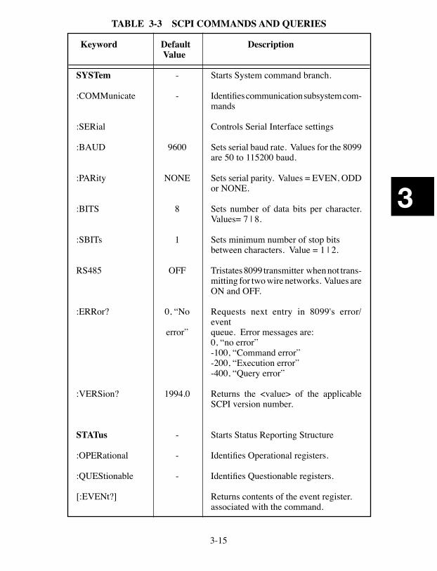
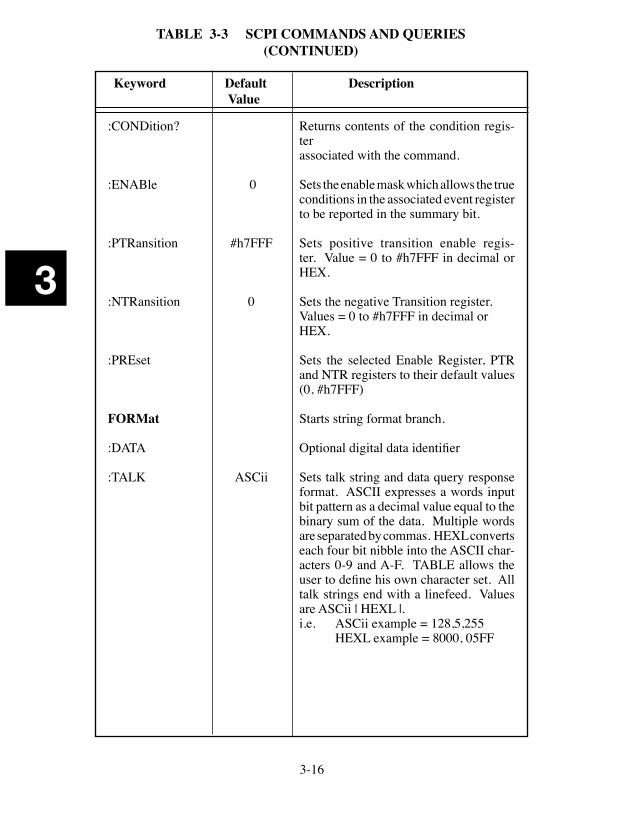
TABLE 3-3 SCPI COMMANDS AND QUERIES
Keyword Default Description Value
SYSTem - Starts System command branch.
:COMMunicate - Identifies communication subsystem com-mands
:SERial Controls Serial Interface settings
:BAUD 9600 Sets serial baud rate. Values for the 8099 are 50 to 115200 baud.
:PARity NONE Sets serial parity. Values = EVEN, ODD or NONE.
:BITS 8 Sets number of data bits per character. Values= 7 | 8.
:SBITs 1 Sets minimum number of stop bits between characters. Value = 1 | 2.
RS485 OFF Tristates 8099 transmitter when not trans-mitting for two wire networks. Values are ON and OFF.
:ERRor? 0, “No Requests next entry in 8099's error/event
error” queue. Error messages are: 0, “no error” -100, “Command error” -200, “Execution error” -400, “Query error”
:VERSion? 1994.0 Returns the <value> of the applicable SCPI version number.
STATus - Starts Status Reporting Structure
:OPERational - Identifies Operational registers.
:QUEStionable - Identifies Questionable registers.
[:EVENt?] Returns contents of the event register. associated with the command.
3-16
3
:CONDition? Returns contents of the condition regis-ter
associated with the command.
:ENABle 0 Sets the enable mask which allows the true conditions in the associated event register to be reported in the summary bit.
:PTRansition #h7FFF Sets positive transition enable regis-ter. Value = 0 to #h7FFF in decimal or HEX.
:NTRansition 0 Sets the negative Transition register. Values = 0 to #h7FFF in decimal or HEX.
:PREset Sets the selected Enable Register, PTR and NTR registers to their default values (0, #h7FFF)
FORMat Starts string format branch.
:DATA Optional digital data identifier
:TALK ASCii Sets talk string and data query response format. ASCII expresses a words input bit pattern as a decimal value equal to the binary sum of the data. Multiple words are separated by commas. HEXL converts each four bit nibble into the ASCII char-acters 0-9 and A-F. TABLE allows the user to define his own character set. All talk strings end with a linefeed. Values are ASCii | HEXL |.
i.e. ASCii example = 128,5,255 HEXL example = 8000, 05FF
TABLE 3-3 SCPI COMMANDS AND QUERIES (CONTINUED)
Keyword Default Description Value
3-17
3
Keyword Default Description Value
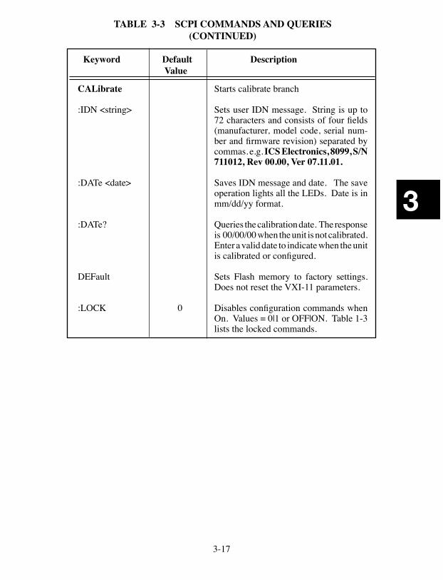
TABLE 3-3 SCPI COMMANDS AND QUERIES (CONTINUED)
CALibrate Starts calibrate branch
:IDN <string> Sets user IDN message. String is up to 72 characters and consists of four fields (manufacturer, model code, serial num-ber and firmware revision) separated by commas. e.g. ICS Electronics, 8099, S/N 711012, Rev 00.00, Ver 07.11.01.
:DATe <date> Saves IDN message and date. The save operation lights all the LEDs. Date is in mm/dd/yy format.
:DATe? Queries the calibration date. The response is 00/00/00 when the unit is not calibrated. Enter a valid date to indicate when the unit is calibrated or configured.
DEFault Sets Flash memory to factory settings. Does not reset the VXI-11 parameters.
:LOCK 0 Disables configuration commands when On. Values = 0|1 or OFF|ON. Table 1-3 lists the locked commands.
3-18
3
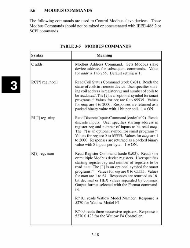
3.6 MODBUS COMMANDS
The following commands are used to Control Modbus slave devices. These Modbus Commands should not be mixed or concatenated with IEEE-488.2 or SCPI commands.
TABLE 3-5 MODBUS COMMANDS
Syntax Meaning
C addr Modbus Address Command. Sets Modbus slave device address for subsequent commands. Value for addr is 1 to 255. Default setting is 1.
RC[?] reg, ncoil Read Coil Status Command (code 0x01). Reads the status of coils in a remote device. User specifies start-ing coil address in register reg and number of coils to be read ncoil. The [?] is an optional symbol for smart programs.(4) Values for reg are 0 to 65535. Values for ninp are 1 to 2000. Responses are returned as a packed binary value with 1 bit per coil. 1 = ON.
RI[?] reg, ninp Read Discrete Inputs Command (code 0x02). Reads discrete inputs. User specifies starting address in register reg and number of inputs to be read ninp. The [?] is an optional symbol for smart programs.(4) Values for reg are 0 to 65535. Values for ninp are 1 to 2000. Responses are returned as a packed binary value with 8 inputs per byte. 1 = ON.
R[?] reg, num Read Register Command (code 0x03). Reads one or multiple Modbus device registers. User specifies starting register reg and number of registers to be read num. The [?] is an optional symbol for smart programs.(4) Values for reg are 0 to 65535. Values for num are 1 to 64. Responses are returned as 16-bit decimal or HEX values separated by commas. Output format selected with the Format command. i.e.
R? 0,1 reads Watlow Model Number. Response is 5270 for Watlow Model F4
R? 0,3 reads three successive registers. Response is 5270,0,123 for the Watlow F4 Controller.
3-19
3
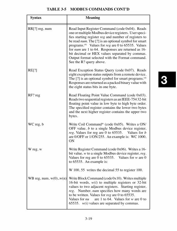
RR[?] reg, num Read Input Register Command (code 0x04). Reads one or multiple Modbus device registers. User speci-fies starting register reg and number of registers to be read num. The [?] is an optional symbol for smart programs.(4) Values for reg are 0 to 65535. Values for num are 1 to 64. Responses are returned as 16-bit decimal or HEX values separated by commas. Output format selected with the Format command. See the R? query above.
RE[?] Read Exception Status Query (code 0x07). Reads eight exception status outputs from a remote device. The [?] is an optional symbol for smart programs.(4) Responses are returned as a packed binary value with the eight status bits in one byte.
RF? reg Read Floating Point Value Command (code 0x03). Reads two sequential registers as an IEEE-754 32-bit floating point value in low byte to high byte order. The specified register contains the lower two bytes and the next higher register contains the upper two bytes.
WC reg, b Write Coil Command* (code 0x05). Writes a ON/OFF value, b to a single Modbus device register, reg. Values for reg are 0 to 65535. Values for b are 0/OFF or 1/ON/255. An example is: WC 1000, ON
W reg, w Write Register Command (code 0x06). Writes a 16-bit value, w to a single Modbus device register, reg. Values for reg are 0 to 65535. Values for w are 0 to 65535. An example is:
W 100, 55 writes the decimal 55 to register 100.
WB reg, num, w(0),.w(n) Write Block Command (code 0x10). Writes multiple 16-bit words, w(i) to multiple registers or 32-bit values to two adjacent registers. Starting register, reg. Number, num specifies how many words are to be written. Values for reg are 0 to 65535.
Values for nu are 1 to 64. Values for w are 0 to 65535. w(i) values are separated by commas.
TABLE 3-5 MODBUS COMMANDS CONT'D
Syntax Meaning
3-20
3
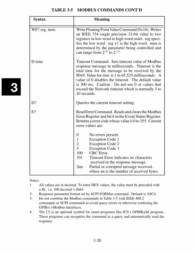
WF? reg, num Write Floating Point Value Command (0x16). Writes an IEEE 754 single precision 32-bit value to two registers in low word to high word order. reg speci-fies the low word. reg +1 is the high word. num is determined by the parameter being controlled and can range from 2127 to 2-127
D time Timeout Command. Sets timeout value of Modbus response message in milliseconds. Timeout is the total time for the message to be received by the 80x9. Value for time is 1 to 65,535 milliseconds. A value of 0 disables the timeout. The default value is 300 ms. Caution - Do not use 0 or values that exceed the Network timeout which is normally 3 to 10 seconds.
D? Queries the current timeout setting.
E? Read Error Command. Reads and clears the Modbus Error Register and bit 6 in the Event Status Register. Returns a error code whose value is 0 to 255. Current error values are:
0 No errors present 1 Exception Code 1 2 Exception Code 2 3 Exception Code 3 100 CRC Error 101 Timeout Error indicates no characters received in the response message. 2nn Partial or corrupted message received.
where nn is the number of received bytes.
Notes:1. All values are in decimal. To enter HEX values, the value must be preceded with
a #h . i.e. 100 decimal = #h642. Response parameter format set by SCPI FORMat command. Default is ASCii3. Do not combine the Modbus commands in Table 3-5 with IEEE-488.2 commands or SCPI commands to avoid query errors or otherwise confusing the
GPIB<->Modbus Interfaces.4. The [?] is an optional symbol for smart programs like ICS’s GPIBKybd program.
These programs can recognize the command as a query and automatically read the response.
TABLE 3-5 MODBUS COMMANDS CONT'D
Syntax Meaning
3-21
3
3.7 LAN PROGRAMMING GUIDELINES
This section provides general directions for linking to the 8099 and hints for writing LAN programs. Refer to ICS's AB80 series Application Notes and the Appendix for additional information about programming VXI-11 devices.
3.7.1 LAN Programming and Timeouts
The VXI-11 protocol provides a way to send data packets and commands to an instrument and to receive data back from instruments over your company network or LAN. As with GPIB Programming, there are a couple things the user must do before using the 8099.
Windows users should:
1. Install a VXI-11 compliant VISA Library (from NI or Agilent). 2. Define the 8099 as a VISA TCP/IP Resource. 3. Write and test the Application Program
Linux/UNIX users should:
1. Install RPC client-side support. 2. Use the system's rpcgen utility to install VXI-11 RPC. 3. Write and test the program. See AB80-3 for RPC programming
Programs written for a LAN instrument need to be organized in the following manner:
1. Open a socket and link to the 8099 and to any other instruments. 2. Body of the test program with instrument reads, writes etc. 3. An exit routine that closes all links and sockets.
Leave the instrument links and channels open until the program is finished to avoid unnecessary program delays and exhausting the devices' resources. Error testing should be built into the program to verify that the called function worked as planned. Test your commands with ICS's VXI-11 keyboard program before adding them to your program. (See Section 3.9 for VXI11_kybd directions). ICS also provides a Error Log Utility to read back soft errors from the 8099 during program debugging. See Section 3.10 for more information about the ErrorLog Utility.
Example Visual Basic programs that make VISA calls are supplied on your Sup-port CD and are available for downloading from ICS's website (www.icselect.com). Use these programs as a starting point for your program.
3-22
3
LAN systems have multiple timeouts. There is the VXI-11 IO_timeout which includes the wait-for-lock-release time and the delays in the module. In the case of the 8099 this also includes the modbus serial timeout value set by the D command. The VISA communication or RPC network timeouts are long timeouts designed to catch network failures.
COMM_Timeout is unique to ICS VXI-11 devices and refers to the time the device's service will go without getting a message from the other party before declaring the link dead. KeepAlive is a background function of the device’s TCP/IP Stack to check the socket connection and is invisible to the applica-tion. Both of these functions will terminate a broken link or channel, release any locks and release the resources for use by another link. Else the device can run out of resources and become inaccessible. There is also a lock timeout that sets the time a command will wait for a device lock to be released before timing out.
COMM_Timeout should be set to a low period like 2-5 minutes when you are first debugging a program and tend to breakout of the program without prop-erly closing the sockets. Later, with a finished program, extend the time to 10 minutes or to a couple of hours to avoid prematurely closing the socket while you are not communicating with the 8099. Hard wired systems are pretty dependable and you can safely extend the 8099’s COMM_Timeout to several hours. Do not set it to 0, which disables the timeout, unless you have a way to physically reset the 8099 if it runs out of resources.
The 8099’s Keep_Alive function should be enabled. Keep_Alive will put a short message on the network, once every 2 hours if there has been no traffic from the client in this time. Only use Keep_Alive if your client application supports it.
The recommendation is to install a background function in your test program to prevent unwanted socket closure during work breaks or unplanned test stop-pages. This function can be set to perform some RPC VXI-11 activity through the socket when nothing has been done for a period of time less than the 8099's COMM_Timeout setting. The background functions should not alter the state of the devices or of the interface. Some non-altering actions are opening and closing a second link to the 8099. All channels need to be exercised once in each instruments' COMM_Timeout period.
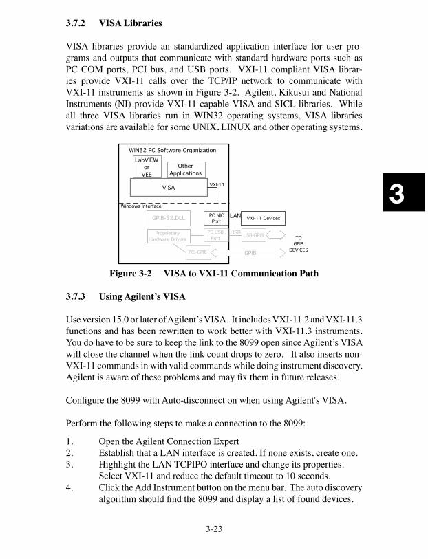
3-23
3
3.7.2 VISA Libraries
VISA libraries provide an standardized application interface for user pro-grams and outputs that communicate with standard hardware ports such as PC COM ports, PCI bus, and USB ports. VXI-11 compliant VISA librar-ies provide VXI-11 calls over the TCP/IP network to communicate with VXI-11 instruments as shown in Figure 3-2. Agilent, Kikusui and National Instruments (NI) provide VXI-11 capable VISA and SICL libraries. While all three VISA libraries run in WIN32 operating systems, VISA libraries variations are available for some UNIX, LINUX and other operating systems.
�����������
���������������������������
����
������������
�����������������
������������������
������������������������������
����
������
���������������
��������
����������
������
�������������
�����������������
Figure 3-2 VISA to VXI-11 Communication Path
3.7.3 Using Agilent’s VISA
Use version 15.0 or later of Agilent’s VISA. It includes VXI-11.2 and VXI-11.3 functions and has been rewritten to work better with VXI-11.3 instruments. You do have to be sure to keep the link to the 8099 open since Agilent’s VISA will close the channel when the link count drops to zero. It also inserts non-VXI-11 commands in with valid commands while doing instrument discovery. Agilent is aware of these problems and may fix them in future releases.
Configure the 8099 with Auto-disconnect on when using Agilent's VISA.
Perform the following steps to make a connection to the 8099:
1. Open the Agilent Connection Expert2. Establish that a LAN interface is created. If none exists, create one.3. Highlight the LAN TCPIPO interface and change its properties. Select VXI-11 and reduce the default timeout to 10 seconds.4. Click the Add Instrument button on the menu bar. The auto discovery
algorithm should find the 8099 and display a list of found devices.
3-24
3
5. Select the 8099 from the resulting instrument list. Check Allow IDN query. Uncheck Host Names. Click OK6. The Connection Expert should verify the device and add it to the
Instrument IO tree.
The user should exit the Agilent Connection Expert after the device is found. Run ICS’s VXI-Error Log Utility if you experience unstable operation, program hangups or see the 8099’s ERR LED blinking often. Use the log to debug and modify your VISA program.
3.7.4 Using Agilent’s SICL Library
Agilent’ SICL Library includes a complete set of VXI-11.2 and VXI-11.3 func-tions and works well with C language and Visual Basic. It is very stable and has been around a long time. Agilent’s SICL User's Guide lists all of SICL's functions and provides easy to follow instructions for creating a LAN Session and for controlling VXI-11 devices. The SICL help file provides detailed function explanations. ICS’ Application Note, AB80-2, describes how to write an interactive Visual Basic program (SICL_kybd) using SICL functions. The example SICL program can be used as a starting point for your program. The Application Note, executable and source files may also be downloaded from ICS’s website.
The hardest part about using the SICL library is setting up the open function to link to the 8099. The SICL_kybd program has a comboBox where the user can enter the 8099's IP address. The Create Link button calls the cmdLink function that closes any open interface links and then opens an interface link to the 8099's IP address.
The 8099 interface link format is:
intfc = iopen(“lan;vxi-11[192.168.0.254]:inst0”)
Establishing an alias like '8099' and then referring to the alias in the iopen com-mand eliminates this problem.
Note that the command ends with 'inst0' which specifies the interface link to an instrument. The IP address shown in the above example is the 8099's default IP address and is a placeholder for the 8099’s current IP address. The SICL_kybd program inserts the user supplied IP address from the comboBox, if the user had entered an address, or it uses the 8099 default IP address if no IP address was entered.
3-25
3
3.7.5 Using Kikusui VISA
Kikusui provides a VISA library that is compliant with IVI VISA specification 5.0. It supports USB, RS-232C, LAN, and GPIB interfaces. It has been tested and found to be compatible with ICS Electronics' GPIB and LAN interfaces. You can download the Kikusui Visa (ki-visa) from Kikusui's website at http://www.kikusui.co.jp/en/download/.
Use ICS's VISAkybd program with the Kikusui VISA to interactively control instruments. VISAkybd does not have a search and find feature so you will have to manually enter the instrument's GPIB address or LAN IP address.
3.7.6 Using National Instruments’ VISA and MAX
National Instruments’ VISA comes with the NI Measurement and Automation Explorer (MAX) and can be downloaded from NI's website. NI's VISA only has VXI-11.3 capability. When manually running the NI VISA Interactive Control Panel, run MAX first to define the TCP/IP Resource. Use LabVIEW version 8.5.1 or later, to minimize problems.
The following steps will let you use MAX to link to the 8099.1. Run MAX. 2. Right click on Devices and Interfaces in the left hand window and
select Create New.2. Select VXI TCP/IP Resource from the pop up window. Press Next.3. Select VXI-11 LAN Instrument. Press Next.4. Select Auto-discovery. Press Next.5. Select which instruments to add. Press Finish to save the instru-
ment.
You can now run the VISA Interactive Control Panel.
1. Select the INSTR TCP/IP Resource you just entered.2. Click the Open VISA Session button.3. Select the BASIC I/O tab.4. Select the Write tab. *IDN? is prefilled in the text box but you can
change it to any command. Press Execute to send the command to the GPIB device.
5. Select the Read tab. Press Execute to read the device’s response. Only execute the read function if you are expecting a reply from the device. Otherwise you will get a timeout error.
6. The remaining tabs let you send a Device Trigger or Device Clear to the device and Serial Poll the device.
3-26
3
3.7.7 Direct Control with TCP/IP
The 8099's WebServer communicates thru port 80. If you write a program to open a socket to port 80 on the 8099 and send a single line containing the URL via the socket, it would be the same as having a browser communicate with the 8099. You can create a small program to visit, examine or control the html page variables. Refer to the html pages supplied with your 8099 for the variables and their functions. An example is:
http://192.168.0.254/temperature.html?input1sp=27.5
3-27
3
3.8 MODBUS PROGRAMMING EXAMPLES
The following section provides information on how to configure the 8099 from a program, and how to send commands to the Modbus slave device. New users should try these simple examples with ICS’s VXI11_kybd program to become familiar with controlling the 8099 and Modbus device(s) over an Ethernet link. Refer to Appendix A1 and A2 for general information about VXI-11 program-ming and to Section 3.9 for directions on using the VXI11_Kybd program.
3.8.2 General Configuration Guidelines
New units are factory set so that they are ready to be used when received. Table 1-3 lists the Factory Settings for the Serial Interface. Verify that the 8099's setting match those in the Modbus device. Use the SCPI commands in Table 3-3 to query or change any 8099 setting.
SYST:COMM:SER:RS485? ‘reads current 485 mode setting SYST:COMM:SER:RS485 1 'sets 485 mode on
If the new setting did not verify or if the red ERR LED came on, query the ESR Register. The command was not executed if the ERR LED came on.
Send *ESR? ‘reads Event Status Register and clears the ERR LED.
Check the ESR reading against the bit pattern in Figure 3-1 to find the cause of the error. Correct and repeat the above steps for each parameter you are changing. When done save the new values.
Send “*SAV 0” ‘save the new configuration
The *SAV 0 command will cause the 8099 to blink all but one of its LEDs. .
3.8.3 Setting the Modbus Device Address
The Modbus device address in the 8099 is set with the 'C' command to match the address set in the desired Modbus device. The 8099 remembers the Modbus address until it is changed. It is only necessary to send the 8099 the 'C' com-mand at the start of the program. If the 8099 is being used with only one Modbus device, the address can be set and saved as part of the 8099’s power on configuration. The 8099 and most Modbus devices default to a Modbus address of 1.
3-28
3
C n ‘sets device address to value n*SAV 0 ‘optional save new default address
Modbus commands should not be mixed on the same command line with IEEE-488.2 and SCPI commands to prevent query errors and confusing the 8099 Interface.
3.8.4 Querying a Modbus Device
The next step is to send a query to the 8099 and read back the response from the Modbus device. The R? command is the basic read command. With the Watlow F4 controller, register 0 is the Watlow Model number register. The ‘?’ is optional and is included so programs like ICS’s VXI-11 Keyboard control programs can automatically read back and display the response from a query. i.e.
R? 0,1 ‘reads Watlow model number ‘Watlow F4 response is 5270
A more realistic command might be to read a measured value. Register numbers and functions vary with different Modbus devices so consult your Modbus de-vice manual for its register numbers and functions. With the Watlow F4 series Controllers, register 100 is the measured temperature value.
R? 100,1 'reads temperature from a Watlow F4
3.8.5 Writing to the Modbus Device
The W command writes 16-bit integers to a register. The command parameters depend upon the specific Modbus device. In the following example, a value of 50 is written to register 300. i.e.
W 300, 50 ‘sets F4 temperature setpoint
The WB command writes to sequential Modbus registers. The Visual Basic TempCltr example program on the Support CD-ROM can be used as an example when writing Temperature Control programs.
3.8.6 32-Bit Variables
Most Modbus devices have 16-bit wide registers for setting a parameter and for reading back data. The prior command examples showed how to read and write to 16-bit registers. Watlow's new Temperature Controllers like the Series SD
3-29
3
and Series PD have 32-bit registers which are accessed as two 16-bit registers. The value is assumed to have three decimal places.
3.8.7 32-Bit Write
To write a set point of 1250 degrees (which is really 1250.000) to Registers 27 and 28, multiply the setpoint value (SP) by 1000 to get 1,250,000. Add 65536 to negative numbers. This produces the setpoint (SP) we want to send. To determine the most significant word (MSW) for Register 27, divide the SP by 2^16 or 65536. To determine the least significant word (LSW) for Register 28, subtract from the SP the result of multiplying the MSW by 2^16 or 65536. i.e.
SP = 1250 * 1000 = 1250000MSW = 1250000 / 65536 = 19LSW = 1250000 - (19 * 65536) = 4816
The 8099 can write each register separately with standard write commands or both registers can be written together with the Write Block command. Ex-amples are:
W 27,19 'writes to register 27W 28,4816 'writes to register 28WB 27,2,19,4816 'writes to registers 27 and 28
3.8.8 32-Bit Read
To read a 32-bit value, two successive 16-bit registers are read and the user's program then puts the values together to form the 32-bit result. An example is reading a process variable from Registers 20 (MSW) and 21 (LSW). The 8099 can be used to read each register individually or to read two successive registers. The commands are:
R? 20,1 'reads register 20R? 21,1 'reads register 21R? 20,2 'reads registers 20 and 21
Both sequences return two numbers to the user. The MSW is returned from Register 20, the LSW from Register 21. Multiply the MSW by 2^16 or 65536 and add it to the LSW. Divide the result by 1000 to scale it to three decimal places.
Reading = ((MSW * 65536) + LSW)/1000
3-30
3
3.8.9 Floating Point Variables
Some new Modbus devices like Watlow's EZ PM series controllers use two consecutive register to control a value or to read back a process variable. The two registers hold an IEEE-754 32-bit floating point word. The registers are read and written to in the low word-upper word order.
3.8.10 Floating Point Write
The WF command writes the num value in floating point format to two con-secutive registers starting with the low word register.
WF 2160, 75 'writes to registers 2160 and 2161
3.8.11 Floating Point Read
The RF? query reads a 32-bit floating point value from two sequential register in low word-upper word order. The RF? does not require the number of register to read since it is fixed at two registers.
RF? 360 'reads registers 360 and 361
3.8.12 Setting Modbus Device Timeouts
The D command sets the time that the 8099 waits to receive a response from the Modbus device. If the 8099 does not receive a response within the time period, it assumes that the Modbus device is not responding and sets the timeout error. Timeout errors can be determined by reading the 8099's Modbus Error Register with the E? query. If the error code is 101 (Modbus timeout) then the timeout period should be lengthened. The command to change the timeout period is:
D 500 ‘sets timeout period to 500 ms
The default time period of 300 milliseconds has proved to be satisfactory for most Watlow controllers but should be verified carefully for your specific Modbus device. Some devices fail to respond within the default time period because they perform periodic calibrations. The recommendation is that your program should have a built-in recovery routine to handle modbus communi-cation errors.
3-31
3
3.8.13 Locking Setup Parameters
All of the 8099’s configuration parameters can be locked to prevent accidental change by the end user. These lockable parameters are noted by a # symbol in Tables 1-3. Locked parameters cannot be queried or changed while locked. Any command that addresses a locked parameter is not executed, the Command Error bit in the Event Status Register is asserted and the ERR LED is lit. The lock function is saved by the *SAV 0 command.
An example is:
CAL:LOCK ON ‘blocks unauthorized changes*SAV 0 ‘saves lock condition
CAL:LOCK OFF ‘unlocks setup parameters
While lock is enabled, the end-user can only change and save any non-locked parameter.
3.8.14 Generating Service Requests (SRQs) from Modbus Errors
Figure 3-1 shows the 8099's Status Reporting Structure. All Modbus Error codes are placed in the Modbus Error Register at the top of the figure. If the proper Event Status and Status Byte register bits are enabled, any Modbus Error code will generate a Service Request. The commands to enable the bits are:
*ESE 64 ‘enables ESR bit 6*SRE 32 ‘enables Status Byte bit 5
Some Modbus Errors set specific bits in the Questionable Event Register. To generate a Service Request from a specific event, its bit must be enabled. The following commands enable Service Requests for Timeouts and CRC errors only:
STAT:QUES:PTR #h3000 ‘enables positive going bits 12 and 13 to set bits in the Questionable Event RegisterSTAT:QUES:ENAB #h3000 ‘enables Event bits 12 and 13*SRE 8 ‘enables Status Byte bit 3
In both cases, the user needs to reset the event cause and clear the Service Request so another error will cause another Service Request. In case one, this is done by reading the Modbus Error Register with the E? query. In case two, the Questionable Event Register must be read to clear the set event bits.
3-32
3
The VXI-11 protocol requires that the user set up a reverse interrupt channel as described in paragraph A2.3. A simpler approach might be to periodically query the Status Byte Register with a device_readstbresp query.
3.8.15 Personalizing the Unit’s IDN Message
The 8099's IDN message can be changed to personalize the unit, to identify the overall assembly as being from your company or to record product history or revision dates. The IDN message is a lockable parameter and if locked, needs to be unlocked before being changed. The format for the IEEE 488.2 IDN message is four fields (company, model#, serial number and revision) sepa-rated by commas and a maximum of 72 characters long. The word “model” may not be used in an IEEE-488.2 IDN message. An example IDN message change sequence is:
CAL:LOCK OFF ‘unlocks all parameters CAL:IDN Acme Test Co, 101, s/n 007, Rev 1 07/08/30 'enters a new IDN message
CAL:LOCK ON ‘relocks all parameters *SAV 0 ‘saves IDN message and lock status
3.8.16 Saving the Configuration
The *SAV 0 command saves the current configuration in nonvolatile Memory. This includes all configuration settings and the current I/O settings. The saved configuration is recalled and the I/O settings restored to their saved state at power turn-on or by the *RCL 0 command. WARNING - Because the Non-volatile Memory has a finite number of write cycles, the *SAV command should not be used inside a program loop. Be sure all settings are correct before saving.
*SAV 0 ‘saves current values and configuration
*RCL 0 ‘recalls the saved configuration
3-33
3
3.9 VXI-11 KEYBOARD PROGRAM
The VXI-11 Keyboard Program ( VXI11_kybd ) is a utility program that lets a user interactively control VXI-11 instruments directly from the computer’s keyboard. The VXI-11 Keyboard Program is the recommended way to test the 8099 after its installation or to try out commands before incorporating them into a program. The VXI-11 Keyboard Program (VXI11_kybd) runs on any WIN32 PC and is provided on the included Support CD.
3.9.1 VXI-11 Keyboard Installation
Select the 'Install VXI-11 Support' option to run the ICS_VXI-11_Install pro-gram. This program installs the VXI-11 Keyboard on your computer along with ICS’s VXI-11.DLL, Microsoft’s Visual Basic 6 Runtime Package and the VXI-11 support documentation.
3.9.2 VXI-11 Keyboard Operation
To run the VXI-11 Keyboard Program, double click the desktop VXI11_kybd icon or run it from the Window’s Start menu by pointing to Programs and then to ICS_Electronics. Select VXI11_kybd from the submenu.
When the VXI-11 Keyboard Program launches, only the Find Server and Cre-ate Link buttons are enabled. The initial steps are to discover and link to the server (8099) and then to the desired instrument (inst0 or inst1)
Press the Find Server button (located in the VXI-11 Server frame) to scan for servers. If you know the IP address, it can be manually entered in the VXI-11 Server window. The number of servers found is displayed in the Device Re-sponse window at the lower left. In the VXI-11 Server frame, use the pulldown arrow to display the found servers. Select the 8099's IP address and press the Select and Create Link button. If the 8099 is not found, use the directions in Section 2.5 to review and correct your network connections to the 8099.
The message in the Device Response window will tell you the link to the 8099 has been established and the number of instruments that have been discovered. Use the pull down arrow on the right side of the Instrument Resource Address window to expose the instruments in the 8099. Select inst0 and press the Select Inst and Link button to link to the instrument. A message is displayed in the Device response window when the link has been created and the remaining VXI11_kybd buttons and controls are enabled.
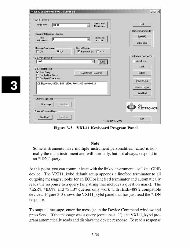
3-34
3
Figure 3-3 VXI-11 Keyboard Program Panel
Note
Some instruments have multiple instrument personalities. inst0 is nor-mally the main instrument and will normally, but not always, respond to an *IDN? query.
At this point, you can communicate with the linked instrument just like a GPIB device. The VXI11_kybd default setup appends a linefeed terminator to all outgoing messages, looks for an EOI or linefeed terminator and automatically reads the response to a query (any string that includes a question mark). The *ESR?, *IDN?, and *STB? queries only work with IEEE-488.2 compatible devices. Figure 3-3 shows the VXI11_kybd panel that has just read the *IDN response.
To output a message, enter the message in the Device Command window and press Send. If the message was a query (contains a ‘?’), the VXI11_kybd pro-gram automatically reads and displays the device response. To read a response
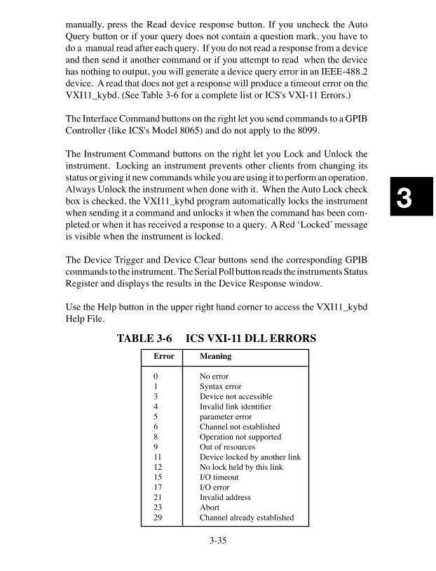
3-35
3
manually, press the Read device response button. If you uncheck the Auto Query button or if your query does not contain a question mark, you have to do a manual read after each query. If you do not read a response from a device and then send it another command or if you attempt to read when the device has nothing to output, you will generate a device query error in an IEEE-488.2 device. A read that does not get a response will produce a timeout error on the VXI11_kybd. (See Table 3-6 for a complete list or ICS's VXI-11 Errors.)
The Interface Command buttons on the right let you send commands to a GPIB Controller (like ICS's Model 8065) and do not apply to the 8099.
The Instrument Command buttons on the right let you Lock and Unlock the instrument. Locking an instrument prevents other clients from changing its status or giving it new commands while you are using it to perform an operation. Always Unlock the instrument when done with it. When the Auto Lock check box is checked, the VXI11_kybd program automatically locks the instrument when sending it a command and unlocks it when the command has been com-pleted or when it has received a response to a query. A Red ‘Locked’ message is visible when the instrument is locked.
The Device Trigger and Device Clear buttons send the corresponding GPIB commands to the instrument. The Serial Poll button reads the instruments Status Register and displays the results in the Device Response window.
Use the Help button in the upper right hand corner to access the VXI11_kybd Help File.
TABLE 3-6 ICS VXI-11 DLL ERRORSError Meaning
0 No error1 Syntax error3 Device not accessible4 Invalid link identifier5 parameter error6 Channel not established8 Operation not supported9 Out of resources11 Device locked by another link12 No lock held by this link15 I/O timeout17 I/O error21 Invalid address23 Abort29 Channel already established
3-36
3
3.10 VXI-11 ERRORLOG UTILITY ICS’S VXI-11 ErrorLog Utility periodically queries an ICS VXI-11 device at its configuration port to see if it has any logged errors. If there are errors, they are read and listed by the ErrorLog Utility. ICS’S VXI-11 ErrorLog Utility is designed to work with ICS Electronic’s VXI-11 products with 80xx series model numbers. The ErrorLog Utility is not intended, nor will it work with VXI-11 products from other companies. 3.10.1 Error Types
An error is defined as a non-standard event. An error may be either a hard error or a soft error. A hard error is such that it prevents further operation of the device, resulting in a hang condition after which the device is no longer functional. Hard errors are shown by a blinking LED pattern if the processor is able to operate the LEDs. A soft error is an error condition that is of momentary condition and will not prevent the device from normal operation.
The occurrence of a soft error will cause the ICS VXI-11 device to momentary flicker the red ERR LED (typically 1/10th of a second). Multiple soft errors may extend the time the ERR LED is turned on. In addition, an error entry is made in the device internal error log. The error log is accessible through the ErrorLog utility. Launching the ErrorLog utility will clear the current contents of the device error log. Future error log entries will then be displayed by the ErrorLog utility. The ErrorLog utility reports soft error conditions and provides some minimal information as to what the error condition means. It is not intended to provide in depth information as to the conditions causing the error. However, the fact that an error occurred and the nature of the error can quite often provide important information and allows the user to isolate the cause of the error and preventing future error conditions. 3.10.2 Running the ErrorLog Utility
To launch the ErrorLog utility, open an MSDOS window and navigate to the ICS Electronics VXI-11 Utilities folder. The ErrorLog utility requires a single command line parameter, which is the IP of the ICS VXI-11 device to be monitored. If the IP is not provided, the ErrorLog utility will default to 192.168.0.254, which is the default shipping address of ICS’s VXI-11 products. The MSDOS window will display an error message if it fails to connect to the VXI-11 server.
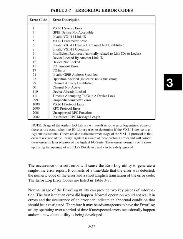
3-37
3
TABLE 3-7 ERRORLOG ERROR CODES
Error Code Error Description
1 VXI-11 Syntax Error3 GPIB Device Not Accessible4 Invalid VXI-11 Link ID5 VXI-11 Parameter Error6 Invalid VXI-11 Channel. Channel Not Established8 Invalid VXI-11 Operation9 Insufficient Resources (normally related to Link IDs or Locks)11 Device Locked By Another Link ID12 Device Not Locked15 I/O Timeout Error17 I/O Error21 Invalid GPIB Address Specified23 Operation Aborted (indicator, not a true error)29 Channel Already Established60 Channel Not Active110 Device Already Locked111 Timeout Attempting To Gain A Device Lock999 Unspecified/unknown error1000 VXI-11 Protocol Error2000 RPC Protocol Error2001 Unsupported RPC Function2002 Insufficient RPC Message Length
NOTE: Usage of the Agilent I/O Library will result in some error log entries. Some of these errors occur when the IO Library tries to determine if the VXI-11 device is an Agilent instrument. Others are due to the incorrect usage of the VXI-11 protocol in the current revision of the library. Agilent is aware of these protocol errors and will correct these errors in later releases of the Agilent I/O Suite. These errors normally only show up during the opening of a SICL/VISA device and can be safely ignored.
The occurrence of a soft error will cause the ErrorLog utility to generate a single-line error report. It consists of a time/date that the error was detected, the numeric code of the error and a short English translation of the error code. The Error Log Error Codes are listed in Table 3-7. Normal usage of the ErrorLog utility can provide two key pieces of informa-tion. The first is that an error did happen. Normal operation would not result in errors and the occurrence of an error can indicate an abnormal condition that should be investigated. Therefore it may be advantageous to have the ErrorLog utility operating over a period of time if unexpected errors occasionally happen and/or a new client utility is being developed.
3-38
3
The second way in which the ErrorLog may be of value is for client program debugging. Usually it is possible to single-step through a program, allowing the user to determine exactly which operation results in the error condition. Then the user can investigate the proper usage of the operation to prevent er-rors in the new program. There are two basic types of soft errors. The first type is a RPC protocol type error which are usually not seen by the typical application developer. They are normally caused by communication protocol errors and should be reported to the developer of the communication package being used. Normally this would be a VISA library, RPC developer, or some other type of communica-tion package.
The second type of error is a procedural type of error. An example of a pro-cedural error is attempting to perform an I/O operation to/from a non-existent device or trying to read data that is not there. These errors are typically seen by the application developer and should be corrected.
3-39
3
3.11 OEM DOCUMENTATION AND CONFIGURATION
3.13.1 Firmware Settings
OEM users can set the module's IDN message to identify the company and product. The Digital I/O configuration can be set to the power turn-on values and saved. The settings can then be locked so the end-user cannot change them.
3.11.2 WebServer Pages
The OEM can customize the 8099's WebServer configuration pages to identify the product and incorporate the company logo by following the guidelines in Application Bulletin AB80-5.
3.11.3 End-User Documentation
OEM users of the this interface 8099 should provide the end-user with the instructions and utility programs necessary to operate the complete system. This is not done by passing on the 8099 manual to the end-user since it does not relate to the end product. In most cases the end-user needs directions for:
1. Setting the product's Network Settings.2. Resetting the Network Settings when he forgets them.2. Using commands to control the overall device. (Includes sending
outputs and reading inputs if applicable). The OEM needs to define the commands in terms of what they do to the overall product and show the end-user how to use them.
3. Using the trigger functions if applicable.4. Using the 488.2 Status Reporting Structure. The OEM needs to define
what the digital inputs mean if they are part of the product, how to enable Service Requests (SRQs) and how to read the registers.
The SCPI Standard requires that the SCPI command tree and SCPI confor-mance information be passed on to the end-user. This means only the active or applicable commands. Edit out all unused commands. All locked commands become invisible to the end-user and should be omitted from the end-user's SCPI command tree and list.
3.11.4 Utility Programs and Drivers
The following utility programs and drivers should be given to the end-user:
3-40
3
1. ICS's VXI-11 Keyboard Program2. ICS's VXI-11 Error Log Utility3. Any programs generated by the OEM to control the end product such
as LabVIEW VIs, etc.
3.11.5 Copyright Release
OEM users of the 8099 Ethernet to Parallel Interface are hereby given permis-sion to copy any portion of this manual, referenced ICS material and utility or example programs for the purpose of documenting systems, maintaining or enhancing sales of systems that incorporate ICS's interfaces. Reproduction of this manual for other purposes without the expressed written consent of ICS Electronics is forbidden.
4
4-1
4
Theory of Operation4.1 INTRODUCTION
This section describes the theory of operation of the 8099 Parallel Interface cards.
4.2 FUNCTIONAL DESCRIPTION
The 8099 is a microprocessor based device that performs the VXI-11 service functions to control its Serial Interface from an IEEE-802.11 network. The 8099 is made up of seven major elements, most of which are interconnected to the microprocessor by a common data, address and control signal bus.
Incoming Ethernet messages are received by the LAN Interface chip. Each received message passes through a TCP Stack before being processed. If the mes-sage is a Modbus command then it is converted into a series of binary characters to make up the Modbus RTU message packet. The Modbus message packet, shown in Figure 4-1, includes the slave device address, the command number, the registers and data (if any) that is being sent to the registers. A checksum is added to make up the complete Modbus RTU packet. The Modbus packet is then placed in the serial transmit buffer. From the serial transmit buffer, the data characters are sequentially placed in the microprocessor's UART where they are serialized, passed through the selected serial driver and outputted at the serial interface.
Packet Format: Addr Cmd Registers.... .data CRC
Figure 4-1 Modbus RTU Packet
All Modbus packets are responded to by the Modbus device. The response packet is either an acknowledgement, an error message or response data.
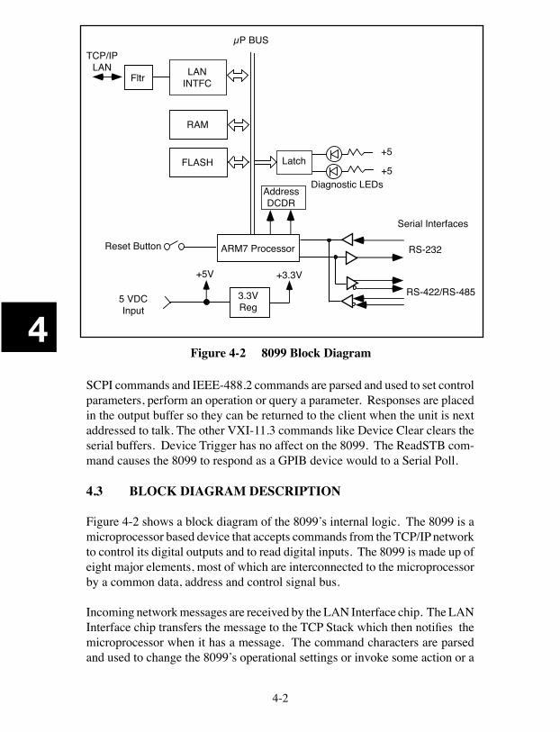
4
4-2
SCPI commands and IEEE-488.2 commands are parsed and used to set control parameters, perform an operation or query a parameter. Responses are placed in the output buffer so they can be returned to the client when the unit is next addressed to talk. The other VXI-11.3 commands like Device Clear clears the serial buffers. Device Trigger has no affect on the 8099. The ReadSTB com-mand causes the 8099 to respond as a GPIB device would to a Serial Poll.
4.3 BLOCK DIAGRAM DESCRIPTION
Figure 4-2 shows a block diagram of the 8099’s internal logic. The 8099 is a microprocessor based device that accepts commands from the TCP/IP network to control its digital outputs and to read digital inputs. The 8099 is made up of eight major elements, most of which are interconnected to the microprocessor by a common data, address and control signal bus.
Incoming network messages are received by the LAN Interface chip. The LAN Interface chip transfers the message to the TCP Stack which then notifies the microprocessor when it has a message. The command characters are parsed and used to change the 8099’s operational settings or invoke some action or a
Figure 4-2 8099 Block Diagram
5 VDCInput
+5V
3.3VReg
+3.3V
ARM7 ProcessorReset Button
RAM
+5
+5Latch
Diagnostic LEDsAddressDCDR
µP BUS
FLASH
LANINTFCFltr
TCP/IPLAN
RS-422/RS-485
RS-232
Serial Interfaces
4
4-3
response. The typical action for the Model 8099 is to transfer data to or from the Serial Interface.
The 8099’s Serial Interface has two sets of drivers and receivers. One set pro-duces or receives the RS-232 single ended, bipolar signals. Typical output levels are ± 8 Vdc. Minimum input levels are ±5 Vdc. The second set gener-ates and receives differential RS-485 signals. The RS-485 driver has more drive capability than the older RS-422 drivers but it makes the same signal levels. The two pairs of signals are connected together externally by the user to form the common RS-485 two-wire network. The Tx/Rx signal pair can be jumpered to an available termination network on the serial connector. The 8099’s RS485 parameter must be set on so the 8099 will not drive the RS-485 network when it is not transmitting a message.
Incoming serial data from the Modbus slave device is received, converted into TTL levels by the desired receiver chip and applied to the UART in the ARM processor. Each received character is temporarily stored in the serial received data buffer. The characters in the received message are counted and verified against the expected response character count. The message is then check summed. If the received message is a valid response, any data is converted in to the correct format and placed in the output buffer where they can be trans-ferred out when the client requests them (Analogous when a GPIB device is addressed to talk) Messages that contain errors or Exception messages cause the 8099 to set bits in the Questionable Register and to place an error value in the Modbus Error Register. The 8099 contains a multilevel Status Byte Register and Event Register structure enables the 8099 to generate a Service Request when errors are detected.
Flash Memory contains all of the 8099's program instructions, command tables, and power turn-on/self test routines. At power turn-on, the 8099 performs a self test on each functional block to determine whether there is a gross system failure. Any self test error is displayed as a pattern of blinking LEDs on the front panel. The error pattern is repeated until the unit is turned off. The RDY LED comes on to indicate a successful completion of the self test routine.
The 8099's configuration settings, serial number and other parameters that are subject to change are saved in a nonvolatile Flash sector. At power on time, the microprocessor copies the saved configuration to RAM where it is used to operate the unit. Any changes made to the settings during run time are not stored in the Flash sector until the user sends the 8099 the *SAV 0 command.
4
4-4
In the 8099, the RAM is a 16-bit wide memory that is used for running the ac-tive program, data storage, operating variables and configuration settings. The 8099 data buffers are mechanized as straight buffers because of the Modbus command-response protocol. The buffers are several times larger than any anticipated message so no data loss ever occurs.
The 8099's power supply is a switching regulator that converts a unregulated 9 to 32 volt DC input to +5 Vdc to run the 8099's internal logic chips. The +5 Vdc is down regulated to make 3.3 Vdc for the ARM processor and support-ing chips that run on 3.3 Vdc power. A DC-DC charge pump converter in the RS-232 transmitter IC makes ± 9 Vdc to operate the RS-232 drivers.
5-1
5
5
Troubleshooting and Repair5.1 INTRODUCTION This section describes the maintenance testing, troubleshooting, and repair procedures for ICS's Model 8099 Ethernet to Digital Interface.
5.2 MAINTENANCE
The 8099 does not require periodic calibration and has no internal adjust-ments.
5.3 TROUBLESHOOTING
Troubleshooting is broken down into selftest errors and operating errors.
5.3.1 Self Test Errors
Self Test errors occur at power turn-on time. The 8099 indicates self- test er-rors by blinking one or more of its LEDs at a 2 Hz rate. Refer to paragraph 5.4 for more information about the Self-Test Errors. The Self Test error codes and their most likely causes are listed in Table 5-1
5.3.2 Operating Failures
Operating failures are those failures that occur while using a unit that has passed its power turn-on self test. Use the fault isolation information in Table 5-1 to narrow the problem down to a specific area. The majority of installation hookup faults can be fixed by following the table and making the necessary corrections to the installation wiring or to the application program.
5-2
5
Hardware failures after the unit has been properly installed and running can be isolated by substituting a known good unit in to the system. If the problem goes away, the fault lies with the removed board. Note the pin or command that fails and contact ICS for repair information. See paragraph 5.5 for repair instructions. If the fault persists, check the wiring especially any flat ribbon cables for faulty or open connectors and the devices connected to the interface board for possible faults..
WARNING
If the fault isolation procedure requires internal measurements, always remove power when dis-assembling or assembling the unit. Use extreme caution during troubleshooting, adjustments, or repair to prevent shorting components and causing further damage to the unit.
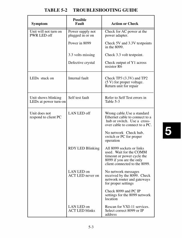
5-3
5
TABLE 5-2 TROUBLESHOOTING GUIDE
PossibleSymptom Fault Action or Check
Unit will not turn on Power supply not Check for AC power at the PWR LED off plugged in or on power adapter. Power in 8099 Check 5V and 3.3V testpoints in the 8099.
3.3 volts missing Check 3.3 volt testpoint.
Defective crystal Check output of Y1 across resistor R6
LEDs stuck on Internal fault Check TP3 (3.3V) and TP2 (5 V) for proper voltage. Return unit for repair
Unit shows blinking Self test fault Refer to Self Test errors in LEDs at power turn-on Table 5-3
Unit does not LAN LED off Wrong cable. Use a standard respond to client PC Ethernet cable to connect to a hub or switch. Use a cross- over cable to connect to a PC. No network Check hub, switch or PC for proper operation
RDY LED Blinking All 8099 sockets or links used. Wait for the COMM timeout or power cycle the 8099 if you are the only client connected to the 8099.
LAN LED on No network messages ACT LED never on received by the 8099. Check network router and gateways for proper settings
Check 8099 and PC IP settings for the 8099 network location
LAN LED on Rescan for VXI-11 services. ACT LED blinks Select correct 8099 or IP address
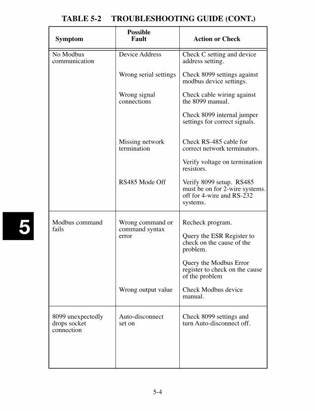
5-4
5
TABLE 5-2 TROUBLESHOOTING GUIDE (CONT.) PossibleSymptom Fault Action or Check
No Modbus Device Address Check C setting and devicecommunication address setting.
Wrong serial settings Check 8099 settings against modbus device settings.
Wrong signal Check cable wiring against connections the 8099 manual.
Check 8099 internal jumper settings for correct signals.
Missing network Check RS-485 cable for termination correct network terminators.
Verify voltage on termination resistors.
RS485 Mode Off Verify 8099 setup. RS485 must be on for 2-wire systems. off for 4-wire and RS-232 systems.
Modbus command Wrong command or Recheck program.fails command syntax error Query the ESR Register to check on the cause of the problem.
Query the Modbus Error register to check on the cause of the problem
Wrong output value Check Modbus device manual.
8099 unexpectedly Auto-disconnect Check 8099 settings and drops socket set on turn Auto-disconnect off.connection
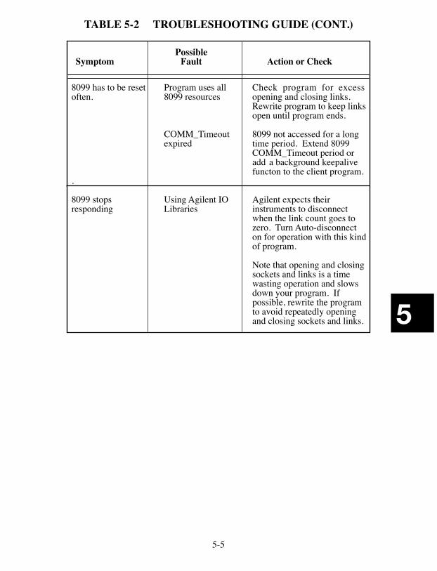
5-5
5
TABLE 5-2 TROUBLESHOOTING GUIDE (CONT.)
PossibleSymptom Fault Action or Check
8099 has to be reset Program uses all Check program for excess often. 8099 resources opening and closing links. Rewrite program to keep links open until program ends.
COMM_Timeout 8099 not accessed for a long expired time period. Extend 8099 COMM_Timeout period or add a background keepalive functon to the client program. .
8099 stops Using Agilent IO Agilent expects their responding Libraries instruments to disconnect when the link count goes to zero. Turn Auto-disconnect on for operation with this kind of program.
Note that opening and closing sockets and links is a time wasting operation and slows down your program. If possible, rewrite the program to avoid repeatedly opening and closing sockets and links.
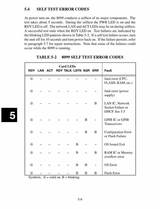
5-6
5
5.4 SELF TEST ERROR CODES
At power turn on, the 8099 conducts a selftest of its major components. The test takes about 5 seconds. During the selftest the PWR LED is on and the RDY LED is off. The network LAN and ACT LEDs may be on during selftest. A successful test ends when the RDY LED on. Test failures are indicated by the blinking LED patterns shown in Table 5-2. If a self test failure occurs, turn the unit off for 10 seconds and turn power back on. If the failure persists, refer to paragraph 5.7 for repair instructions. Note that some of the failures could occur while the 8099 is running.
TABLE 5-2 8099 SELF TEST ERROR CODES
Card LEDs RDY LAN ACT RDY TALK LSTN SQR ERR Fault
⊕ − − − − − − − fatal error (CPU, FLASH, RAM..etc.)
⊕ − − − − − − − fatal error (power supply)
⊕ − − − − − − Β LAN IC, Network Socket Failure or DHCP. See 5.5
⊕ − − − − − Β − GPIB IC or GPIB Transceivers
⊕ − − − − − Β Β Configuration Error or Flash Failure
⊕ − − − − Β − − OS Issued Exit
⊕ − − − − Β − Β RAM IC or Memory overflow error
⊕ − − − − Β Β − OS Error
⊕ − − − − Β Β Β Flash Error Symbols: ⊕ = solid on, B = blinking
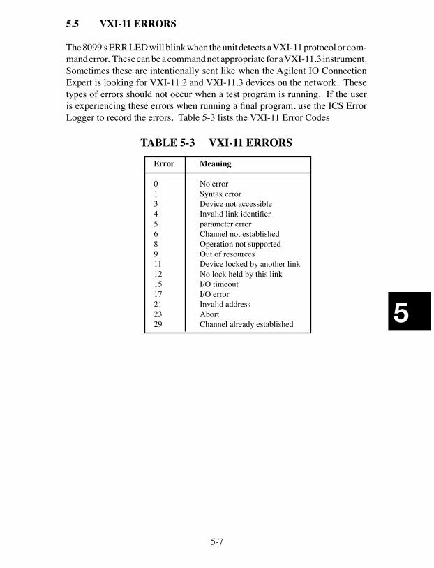
5-7
5
5.5 VXI-11 ERRORS
The 8099's ERR LED will blink when the unit detects a VXI-11 protocol or com-mand error. These can be a command not appropriate for a VXI-11.3 instrument. Sometimes these are intentionally sent like when the Agilent IO Connection Expert is looking for VXI-11.2 and VXI-11.3 devices on the network. These types of errors should not occur when a test program is running. If the user is experiencing these errors when running a final program, use the ICS Error Logger to record the errors. Table 5-3 lists the VXI-11 Error Codes
TABLE 5-3 VXI-11 ERRORS
Error Meaning
0 No error1 Syntax error3 Device not accessible4 Invalid link identifier5 parameter error6 Channel not established8 Operation not supported9 Out of resources11 Device locked by another link12 No lock held by this link15 I/O timeout17 I/O error21 Invalid address23 Abort29 Channel already established
5-8
5
5.6 REVERTING TO FACTORY SETTINGS
5.6.1 Factory Network Settings
The 8099 can be reset to the default network settings listed in Table 1-3 at any time by holding the LAN Reset Button in for 5 seconds while applying power to the board. The TALK, LSTN and SRQ LEDs all blink on momentarily when the board is changed back to its default settings. The Digital I/O configuration values are not affected by the LAN Reset operation.
5.6.2 Factory Digital I/O Configuration
The 8099's Digital IO configuration can be reset to the factory settings listed in Table 1-3 by sending the unit the CAL:DEFAULT command or with an internal jumper as directed below. The CAL:DEFAULT command resets the current values in RAM and saves them to the 8099's Flash memory. CAL:DEFAULT does not change the network settings.
1. Turn the unit off and disconnect all cables.
2. Touch your hands to the shiny metal part of the computer or to some other instrument that is grounded to the AC power lines and to earth.
3. Remove the PC assembly from its case by undoing the two rear panel screws and the two screws on the bottom of the case. Press the Power Switch to slide the PC assembly out of the case.
4. Locate the W1 (DEF) jumper pins as shown in Figures 2-9 or 2-10. Use a jumper or clip lead to short the two W1 (DEF) pins.
5. Apply power to the board. Keep the until the DEF pins shorted while he board boots up. This will take approximately 10 seconds. The TALK, LSTN and SRQ LEDs will blink for 0.5 seconds as the default configuration is saved in the flash memory. Repeat step 4 if you do not see the TALK, LSTN and SRQ LEDs blink.
6. Power the unit off. Remove the W1 jumper.
7. To reassemble the unit, slide the PC assembly back into its case and carefully guide the Power Switch through the front panel overlay. Replace the screws. Do not over-tighten the rear panel screws.
5. Power cycle the unit and verify the network settings.
5-9
5
5.7 UPDATING FIRMWARE
The 80xx products are designed so that their firmware can be updated in the field. This is a simple procedure that the user can perform without returning the unit to the factory.
1. Connect the 8099 to your PC as described in section 2.5.1. Apply power to the 8099.
2. Download the latest Firmware Update for the 8099 from ICS Electron-ics website, http://www.icselect.com.
3. Unzip the file into new directory and run the Update Utility.
4. Click on the Find Server button to scan for VXI-11.3 servers. The IP addresses of the found servers are displayed in the adjacent window. Use the pulldown arrow to display the found servers. Select the 8099's IP address and press the Select and Create Link button to link to your 8099.
When you link to the 8099, the program will check its revision status to see if it is an 8099 and if it needs updating.
5. If the 8099 needs updating, click the Update Flash button to start the update process. Do not interrupt this process. The three yellow GPIB LEDs (TALK, LSTN and SRQ) will blink while the new program is being stored in the 8099's flash memory.
6. The Update Utility will reboot the 8099 so the changes just made can take affect. Wait until the RDY LED comes on and then relink to the 8099 as described in step 4 above.
. CAUTION
Do not exit the Update Utility until told to do so. The Update Utility may need to reboot several times to complete the update process.
7. When done, power the unit off and back on. Verify that it passes its self test and that you can communicate with it using the VXI-11 keyboard program or with a browser.
5-10
5
5.8 SANITIZING PROCEDURE
The 8099 the following memory elements: RAM, 1 M x 16-bit memory Flash, 2 M x 8-bit memory Processor memory
The RAM and processor memory contents are lost when power is turned off. The Flash memory contains one sector that contains user saved variables. The other sectors are used for the unit's firmware or are spare sectors for future program use. A typical user does not have access to the program or to the spare sectors.
The Flash memory variable sector can be restored to factory settings by per-forming the following steps:
1. Follow the steps in paragraph 5.6.1 to restore the network settings
2. Use ICS's VXI11_kybd utility to link to the board. (See para 3.9)
3. Send the board the following commands with all capital letters: CAL:DATE UNCAL CAL:DEFAULT CAL:DATE mm-dd-yy 'use today's date
The RAM memory contents should be lost when power is turned off. To be sure all data and code remnants are fully removed from the RAM, perform the following steps:
1. Turn the unit off and disconnect all cables.
2. Touch your hands to the shiny metal part of the computer or to some other instrument that is grounded to the AC power lines and to earth.
3. Remove the PC assembly from its case by undoing the two rear panel screws and the two screws on the bottom of the case. Press the Power Switch to slide the PC assembly out of the case.
4. Locate the 3.3 V testpoint (TP1) and use a jumper to connect it to the GND testpoint (TP2). Leave the test points connected for 1 hour or longer to drain any residual charge out of the CMOS RAM chip.

5-11
5
5. Remove the jumper.
6. To reassemble the unit, slide the PC assembly back into its case and carefully guide the Power Switch through the front panel overlay. Replace the screws. Do not over-tighten the rear panel screws.
7. Reconnect the power and Ethernet cables to the unit.
8. Turn power on. Verify that the unit passes its selftest and that the LEDs light normally.
5-12
5
5.9 REPAIR PROCEDURE
Repair of the 8099 is done by the user or by returning the unit to the factory or to your local distributor. Units in warranty should always be returned to the factory or else repaired only after receiving permission to do so from an ICS customer service representative.
When returning a unit, a board assembly, or other products to ICS for repair, it is necessary to go through the following steps:
1. Contact the ICS customer service department and ask for a return material authorization (RMA) number. An ICS application engineer will want to discuss the problem at this time to verify that the unit needs to be returned, or to assist in correcting the problem. We have discovered that one-third of the difficulties customers call about can be resolved over the phone as opposed to returning a unit for repair.
2. Write a description of the problem and attach it to the material being returned. Describe the installation, system failure symptoms, and how it was being used. If the item being returned is a board assembly, de-scribe how you isolated the fault to it. Include your name and phone number so we can call you if we have any questions. Remember, we need to locate the problem in order to fix it.
3. Pack the item with the fault description in a box large enough to ac-commodate a minimum of two inches of packing material on all four sides, the top, and the bottom of the box. Securely seal the box.
4. Mark the shipping label to the attention of the RMA#. The RMA number is very important since it is our way of identifying your unit in order to return it to you.
5. Ship the box to ICS freight prepaid. ICS does not pay freight to return the unit to ICS, but will prepay the freight to return the repaired item to you.
A-1
A1
AppendixAPPENDIX PAGE
A1 VXI-11 Introduction A-2A1.1 IEEE 488.1 Bus A-2A1.2 IEEE 488.2 Standard A-5A1.3 SCPI Commands A-8
A2 VXI-11 Protocol and Example Program A-11A2.1 Sockets, Channels and Links A-11A2.2 Auto-disconnect A-13A2.3 Service Requests A-13A2.4 Transferring Data A-14A2.5 An Example VISA Program A-14
A3 VXI-11 RPC Gen Information A-17A3-B Basic RPC Programming A-17A3-C VXI-11 RPCL A-18
A4 ICS Configuration RPC Protocol A-22A4-B Configuration Protocol A-23A4-C Detailed Configuration Messages A-26A4-D RPCL Listing A-51
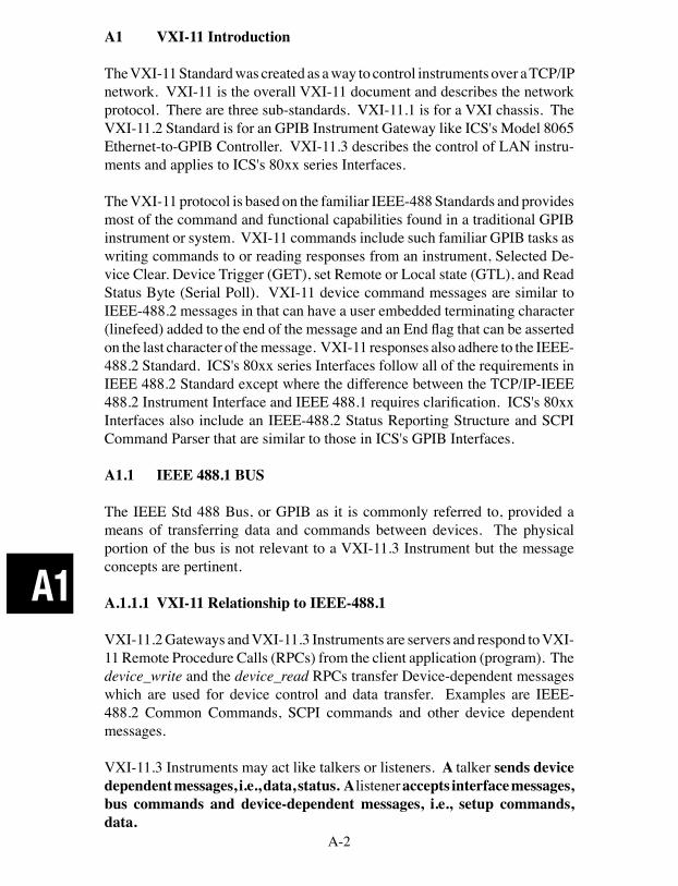
A-2
A1
A1 VXI-11 Introduction
The VXI-11 Standard was created as a way to control instruments over a TCP/IP network. VXI-11 is the overall VXI-11 document and describes the network protocol. There are three sub-standards. VXI-11.1 is for a VXI chassis. The VXI-11.2 Standard is for an GPIB Instrument Gateway like ICS's Model 8065 Ethernet-to-GPIB Controller. VXI-11.3 describes the control of LAN instru-ments and applies to ICS's 80xx series Interfaces.
The VXI-11 protocol is based on the familiar IEEE-488 Standards and provides most of the command and functional capabilities found in a traditional GPIB instrument or system. VXI-11 commands include such familiar GPIB tasks as writing commands to or reading responses from an instrument, Selected De-vice Clear. Device Trigger (GET), set Remote or Local state (GTL), and Read Status Byte (Serial Poll). VXI-11 device command messages are similar to IEEE-488.2 messages in that can have a user embedded terminating character (linefeed) added to the end of the message and an End flag that can be asserted on the last character of the message. VXI-11 responses also adhere to the IEEE-488.2 Standard. ICS's 80xx series Interfaces follow all of the requirements in IEEE 488.2 Standard except where the difference between the TCP/IP-IEEE 488.2 Instrument Interface and IEEE 488.1 requires clarification. ICS's 80xx Interfaces also include an IEEE-488.2 Status Reporting Structure and SCPI Command Parser that are similar to those in ICS's GPIB Interfaces.
A1.1 IEEE 488.1 BUS
The IEEE Std 488 Bus, or GPIB as it is commonly referred to, provided a means of transferring data and commands between devices. The physical portion of the bus is not relevant to a VXI-11.3 Instrument but the message concepts are pertinent.
A.1.1.1 VXI-11 Relationship to IEEE-488.1
VXI-11.2 Gateways and VXI-11.3 Instruments are servers and respond to VXI-11 Remote Procedure Calls (RPCs) from the client application (program). The device_write and the device_read RPCs transfer Device-dependent messages which are used for device control and data transfer. Examples are IEEE-488.2 Common Commands, SCPI commands and other device dependent messages.
VXI-11.3 Instruments may act like talkers or listeners. A talker sends device dependent messages, i.e., data, status. A listener accepts interface messages, bus commands and device-dependent messages, i.e., setup commands, data.
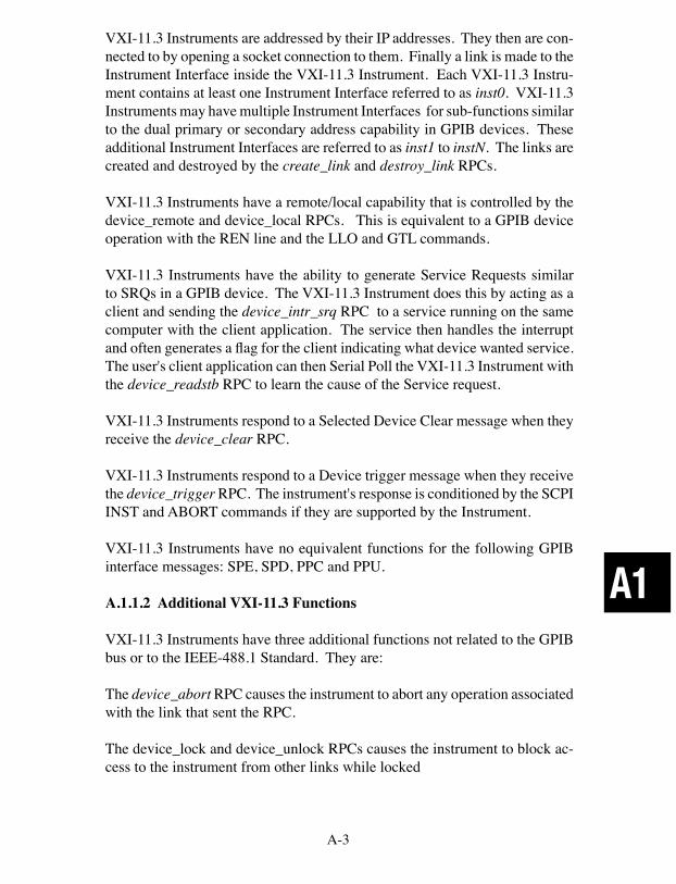
A-3
A1
VXI-11.3 Instruments are addressed by their IP addresses. They then are con-nected to by opening a socket connection to them. Finally a link is made to the Instrument Interface inside the VXI-11.3 Instrument. Each VXI-11.3 Instru-ment contains at least one Instrument Interface referred to as inst0. VXI-11.3 Instruments may have multiple Instrument Interfaces for sub-functions similar to the dual primary or secondary address capability in GPIB devices. These additional Instrument Interfaces are referred to as inst1 to instN. The links are created and destroyed by the create_link and destroy_link RPCs.
VXI-11.3 Instruments have a remote/local capability that is controlled by the device_remote and device_local RPCs. This is equivalent to a GPIB device operation with the REN line and the LLO and GTL commands.
VXI-11.3 Instruments have the ability to generate Service Requests similar to SRQs in a GPIB device. The VXI-11.3 Instrument does this by acting as a client and sending the device_intr_srq RPC to a service running on the same computer with the client application. The service then handles the interrupt and often generates a flag for the client indicating what device wanted service. The user's client application can then Serial Poll the VXI-11.3 Instrument with the device_readstb RPC to learn the cause of the Service request.
VXI-11.3 Instruments respond to a Selected Device Clear message when they receive the device_clear RPC.
VXI-11.3 Instruments respond to a Device trigger message when they receive the device_trigger RPC. The instrument's response is conditioned by the SCPI INST and ABORT commands if they are supported by the Instrument.
VXI-11.3 Instruments have no equivalent functions for the following GPIB interface messages: SPE, SPD, PPC and PPU.
A.1.1.2 Additional VXI-11.3 Functions
VXI-11.3 Instruments have three additional functions not related to the GPIB bus or to the IEEE-488.1 Standard. They are:
The device_abort RPC causes the instrument to abort any operation associated with the link that sent the RPC.
The device_lock and device_unlock RPCs causes the instrument to block ac-cess to the instrument from other links while locked
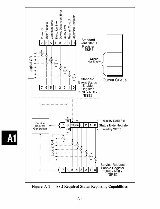
A-4
A1
Figure A-1 488.2 Required Status Reporting Capabilities
Pow
er O
nU
ser R
eque
st
Com
man
d Er
ror
Exec
utio
n Er
ror
Dev
ice
Dep
ende
nt E
rror
Que
ry E
rror
Req
uest
Con
trol
Ope
ratio
n C
ompl
ete
StandardEvent Status
Register*ESR?
7 6 5 4 3 2 1 0
7 6 5 4 3 2 1 0
Logi
cal O
R
&&
&&
&&
&& Standard
Event StatusEnable
Register*ESE <NRf>
*ESE?
QueueNot-Empty
7 5 4 3 2 1 0
Logi
cal O
R
&&
&&
&&
&
7 6 3 2 1 0RQS
MSSESB MAV
{
{ServiceRequest
Generation
Output Queue
Status Byte Registerread by Serial Poll
read by *STB?
Service RequestEnable Register
*SRE <NRf>*SRE?
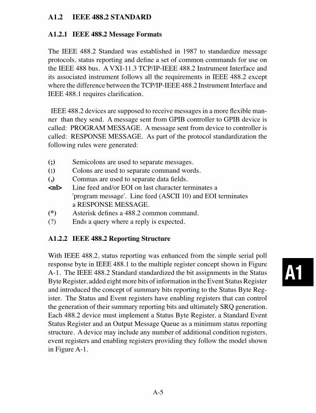
A-5
A1
A1.2 IEEE 488.2 STANDARD
A1.2.1 IEEE 488.2 Message Formats
The IEEE 488.2 Standard was established in 1987 to standardize message protocols, status reporting and define a set of common commands for use on the IEEE 488 bus. A VXI-11.3 TCP/IP-IEEE 488.2 Instrument Interface and its associated instrument follows all the requirements in IEEE 488.2 except where the difference between the TCP/IP-IEEE 488.2 Instrument Interface and IEEE 488.1 requires clarification.
IEEE 488.2 devices are supposed to receive messages in a more flexible man-ner than they send. A message sent from GPIB controller to GPIB device is called: PROGRAM MESSAGE. A message sent from device to controller is called: RESPONSE MESSAGE. As part of the protocol standardization the following rules were generated:
(;) Semicolons are used to separate messages.(:) Colons are used to separate command words.(,) Commas are used to separate data fields.<nl> Line feed and/or EOI on last character terminates a 'program message'. Line feed (ASCII 10) and EOI terminates a RESPONSE MESSAGE.(*) Asterisk defines a 488.2 common command.(?) Ends a query where a reply is expected.
A1.2.2 IEEE 488.2 Reporting Structure
With IEEE 488.2, status reporting was enhanced from the simple serial poll response byte in IEEE 488.1 to the multiple register concept shown in Figure A-1. The IEEE 488.2 Standard standardized the bit assignments in the Status Byte Register, added eight more bits of information in the Event Status Register and introduced the concept of summary bits reporting to the Status Byte Reg-ister. The Status and Event registers have enabling registers that can control the generation of their summary reporting bits and ultimately SRQ generation. Each 488.2 device must implement a Status Byte Register, a Standard Event Status Register and an Output Message Queue as a minimum status reporting structure. A device may include any number of additional condition registers, event registers and enabling registers providing they follow the model shown in Figure A-1.
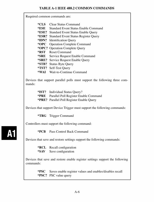
A-6
A1
TABLE A-1 IEEE 488.2 COMMON COMMANDS
Required common commands are:
*CLS Clear Status Command *ESE Standard Event Status Enable Command *ESE? Standard Event Status Enable Query *ESR? Standard Event Status Register Query *IDN? Identification Query *OPC Operation Complete Command *OPC? Operation Complete Query *RST Reset Command *SRE Service Request Enable Command *SRE? Service Request Enable Query *STB? Status Byte Query *TST? Self-Test Query *WAI Wait-to-Continue Command
Devices that support parallel polls must support the following three com-mands:
*IST? Individual Status Query? *PRE Parallel Poll Register Enable Command *PRE? Parallel Poll Register Enable Query
Devices that support Device Trigger must support the following commands:
*TRG Trigger Command
Controllers must support the following command: *PCB Pass Control Back Command
Devices that save and restore settings support the following commands:
*RCL Recall configuration *SAV Save configuration
Devices that save and restore enable register settings support the following commands:
*PSC Saves enable register values and enables/disables recall *PSC? PSC value query

A-7
A1
A1.2.3 IEEE 488.2 Common Commands
The IEEE 488.2 Standard also mandated a list of required and optional Com-mon Commands that all 488.2 devices could support. All of the Common Commands start with an asterisk. Commands that end with a question mark are queries. Query responses can be an ASCII number or an ASCII string. Other numerical formats are legal as long as the device supports the required ASCII format. Table A-1 lists the IEEE 488.2 Common Commands.
A1.2.4 IEEE 488.2 Differences From IEEE 488.1
The user who is familiar with the older 488.1 devices should take the following differences into account when programming a 488.2 device.
A 488.2 device outputs the Status Byte Register contents plus the RQS bit in response to a serial poll. The RQS bit is reset by the serial poll. The same 488.2 device outputs the Status Byte Register contents plus the MSS bit in response to a *STB? query. The MSS bit is cleared when the condition is cleared.
488.2 restricts the Device Clear to only clearing the device's buffers and pend-ing operations. It does not clear the Status Reporting Structure or the output lines. Use *CLS to clear the Status Structure and *RST or *RCL to reset the outputs.
488.2 commands are really special data messages and are executed by the device's parser. Always allow sufficient time for the parser to execute the commands before sending the device a 488.1 command. i.e. a Device Clear sent too soon will erase any pending commands and reset the parser.
Enable Register values are only saved and restored if the *PSC command is 0. A *PSC command of 1 causes zeros to be loaded into the enable registers when the unit is next reset or powered on.
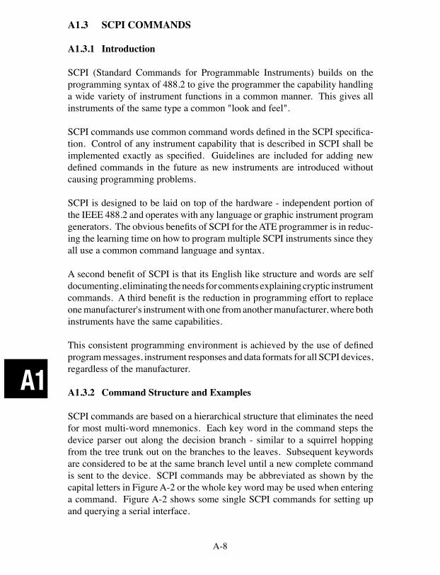
A-8
A1
A1.3 SCPI COMMANDS
A1.3.1 Introduction
SCPI (Standard Commands for Programmable Instruments) builds on the programming syntax of 488.2 to give the programmer the capability handling a wide variety of instrument functions in a common manner. This gives all instruments of the same type a common "look and feel".
SCPI commands use common command words defined in the SCPI specifica-tion. Control of any instrument capability that is described in SCPI shall be implemented exactly as specified. Guidelines are included for adding new defined commands in the future as new instruments are introduced without causing programming problems.
SCPI is designed to be laid on top of the hardware - independent portion of the IEEE 488.2 and operates with any language or graphic instrument program generators. The obvious benefits of SCPI for the ATE programmer is in reduc-ing the learning time on how to program multiple SCPI instruments since they all use a common command language and syntax.
A second benefit of SCPI is that its English like structure and words are self documenting, eliminating the needs for comments explaining cryptic instrument commands. A third benefit is the reduction in programming effort to replace one manufacturer's instrument with one from another manufacturer, where both instruments have the same capabilities.
This consistent programming environment is achieved by the use of defined program messages, instrument responses and data formats for all SCPI devices, regardless of the manufacturer.
A1.3.2 Command Structure and Examples
SCPI commands are based on a hierarchical structure that eliminates the need for most multi-word mnemonics. Each key word in the command steps the device parser out along the decision branch - similar to a squirrel hopping from the tree trunk out on the branches to the leaves. Subsequent keywords are considered to be at the same branch level until a new complete command is sent to the device. SCPI commands may be abbreviated as shown by the capital letters in Figure A-2 or the whole key word may be used when entering a command. Figure A-2 shows some single SCPI commands for setting up and querying a serial interface.
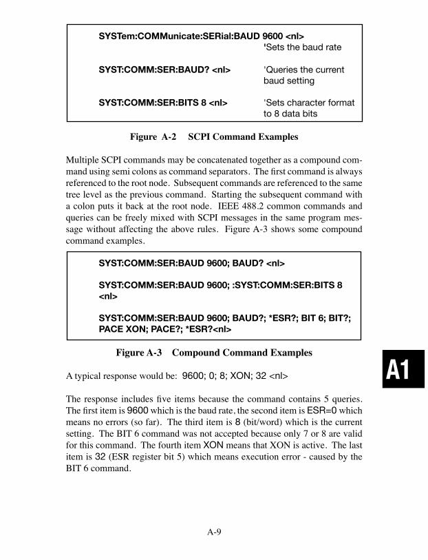
A-9
A1
SYSTem:COMMunicate:SERial:BAUD 9600 <nl> 'Sets the baud rate
SYST:COMM:SER:BAUD? <nl> 'Queries the current baud setting
SYST:COMM:SER:BITS 8 <nl> 'Sets character format to 8 data bits
Figure A-2 SCPI Command Examples
Multiple SCPI commands may be concatenated together as a compound com-mand using semi colons as command separators. The first command is always referenced to the root node. Subsequent commands are referenced to the same tree level as the previous command. Starting the subsequent command with a colon puts it back at the root node. IEEE 488.2 common commands and queries can be freely mixed with SCPI messages in the same program mes-sage without affecting the above rules. Figure A-3 shows some compound command examples.
SYST:COMM:SER:BAUD 9600; BAUD? <nl>
SYST:COMM:SER:BAUD 9600; :SYST:COMM:SER:BITS 8 <nl>
SYST:COMM:SER:BAUD 9600; BAUD?; *ESR?; BIT 6; BIT?; PACE XON; PACE?; *ESR?<nl>
Figure A-3 Compound Command Examples
A typical response would be: 9600; 0; 8; XON; 32 <nl>
The response includes five items because the command contains 5 queries. The first item is 9600 which is the baud rate, the second item is ESR=0 which means no errors (so far). The third item is 8 (bit/word) which is the current setting. The BIT 6 command was not accepted because only 7 or 8 are valid for this command. The fourth item XON means that XON is active. The last item is 32 (ESR register bit 5) which means execution error - caused by the BIT 6 command.
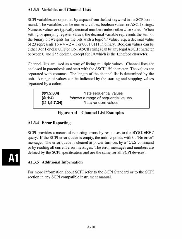
A-10
A1
A1.3.3 Variables and Channel Lists
SCPI variables are separated by a space from the last keyword in the SCPI com-mand. The variables can be numeric values, boolean values or ASCII strings. Numeric values are typically decimal numbers unless otherwise stated. When setting or querying register values, the decimal variable represents the sum of the binary bit weights for the bits with a logic '1' value. e.g. a decimal value of 23 represents 16 + 4 + 2 + 1 or 0001 0111 in binary. Boolean values can be either 0 or 1 or else OFF or ON. ASCII strings can be any legal ASCII character between 0 and 255 decimal except for 10 which is the Linefeed character.
Channel lists are used as a way of listing multiple values. Channel lists are enclosed in parenthesis and start with the ASCII '@' character. The values are separated with commas. The length of the channel list is determined by the unit. A range of values can be indicated by the starting and stopping values separated by a colon.
(@1,2,3,4) 'lists sequential values(@ 1:4) 'shows a range of sequential values(@ 1,5,7,34) 'lists random values
Figure A-4 Channel List Examples
A1.3.4 Error Reporting
SCPI provides a means of reporting errors by responses to the SYST:ERR? query. If the SCPI error queue is empty, the unit responds with 0, "No error" message. The error queue is cleared at power turn-on, by a *CLS command or by reading all current error messages. The error messages and numbers are defined by the SCPI specification and are the same for all SCPI devices.
A1.3.5 Additional Information
For more information about SCPI refer to the SCPI Standard or to the SCPI section in any SCPI compatible instrument manual.
A-11
A2
A2 VXI-11 PROTOCOL AND EXAMPLE PROGRAM
This Appendix describes the VXI-11 Protocol, its applicability to ICS's 80xx series Interfaces and includes a C language VISA program.
The VXI-11 protocol uses Remote Procedure Calls (RPC) that provides an invisible communication medium allowing the developer to concentrate on his program. Remote Procedure Calls are requests sent from a client, such as the user's program, to a remote server to carry out the instruction. Responses are re-turned to every RPC so the client can be sure the request was accomplished.
Windows users can use VXI-11 compliant VISA libraries like those from National Instruments or Agilent that include the capability to make RPC calls VXI-11.3 Instruments like ICS's 80xx Interfaces. That way, VXI-11.3 Instru-ments can be programmed with familiar graphical applications like LabView or VEE. Both applications call a VISA layer that makes VXI-11 calls over the TCP/IP network. C and Visual Basic programs can be written with SICL or VISA calls to control VXI-11.3 Instruments.
Linux, UNIX or any other flavor of UNIX like SunOS, IBM-AIX, HP-UX, or Apple's OS X, can communicate with the VXI-11.3 Instruments through either with RPC over TCP/IP. The VXI-11 Specification, available at http://www.vxibus.org or from ICS Electronic's website, includes a RPCgen header file listing that can be used to generate RPC calls. RPC calls can be used with virtually any operating system that has TCP/IP communication capability and a RPCgen utility. Refer to ICS's Application Notes APB80-3 for more informa-tion about RPC Programming.
Java users can write RPC applications that run on nearly all computer platforms with the Java library from jGPIBenet project on SourceForge. Refer to ICS's Application Notes for detailed information on programming VXI-11 devices.
A2.1 Sockets, Channels and Links
VXI-11 devices, like ICS's 80xx series Interfaces, use a socket connection for bi-directional communication with a client which is the application program running in a computer. Sockets maybe thought of as pipes that support multiple links. After the socket connection is established, the client must establish a link to the instrument to communicate with it.
ICS's 80xx series Interfaces have 15 sockets for connection with multiple clients at a time and a 16th socket for UDP communication. UDP protocol may be used initially when the client scans for a VXI-11 server. The TCP/IP socket
A-12
A2
communication is used when the client links to the 80xx. The 80xx only sup-ports VXI-11 commands via TCP and not via UDP.
The initial socket connection to an VXI-11 Instrument establishes the Core channel which can handle multiple device links and locks. The client can create an Abort channel to clear Core channel command hangups. The Abort channel uses an additional TCP/IP socket. An Interrupt channel can be created from the 80xx (acting as an RPC client) to notify the application that a Service Request (SRQ) has occurred. Interrupt channels share a separate TCP/IP socket that does not count as one of the 80xx’s 15 Core or Abort sockets. If the 80xx runs out of resources (sockets, links or locks), it blinks its RDY LED until the shortage has been cured, typically by a socket or channel timeout.
The user normally links to the device's inst0 instrument interface. Interface inst0 is typically used for all configuration and data transfer commands. Once the link is made to inst0, the client can communicate with, control and query the 80xx just as he would do with a standard GPIB test program. The client can lock the link so that no other client can communicate with that instrument until he is finished with it. Locking is only recommended if the device connection is such that it could be operated by another user. Some VXI-11.3 instruments have additional interfaces , inst1 to instn, that are used for other purposes. An example is he 8063 which uses inst1 for transparent data transfer.
Sockets should be closed gracefully to prevent the 80xx or any other VXI-11 Instrument from running out of resources. Graceful socket closure requires several socket layer messages between the client and server sockets. Most socket close commands just ask the operating system to close the socket. The sockets often stay open for tens of minutes until the operating system gets around to closing them. The best way to close a socket is to do an immediate graceful socket closure instead of just letting the operating system close the socket at some later time. Note that if a connection is broken while one of its links is locked, the link stays locked until either the broken connection is detected (by COMM_Timeout or KeepAlive) or the 80xx is power cycled. Reconnecting from the same client does not allow unlocking since the new connection is through a different socket. The new socket has its own channels, links and locks and cannot manipulate resources owned by another socket.
Two broken link discovery methods are COMM_Timeout and KeepAlive. The COMM_Timeout setting allows the VXI-11 device to recover channels that have not had any client activity for a set period of time. The KeepAlive setting allows the VXI-11 device to test the client socket connection on a periodic basis. When the device closes a socket, the socket and all of its resources (links and
A-13
A2
locks) become available to another client.
The 80xx’s COMM_Timeout can be set to a low period like 3-5 minutes when the user is first debugging a program and tends to breakout of the program without properly closing the sockets. Later, with a finished program, extend the time to 10 minutes or even hours to avoid prematurely closing the socket while you are not communicating with the 80xx. Hard wired systems are pretty dependable and you can extend the 80xx’s COMM_Timeout to several hours or even days. Do not set it to 0, which disables the timeout, unless you have a way to physically reset the 80xx if it runs out of resources. A temporary setting of 0 is useful when debugging third party software.
A2.2 Auto-disconnect
Agilent Instruments have a non-standard behavior that closes (aborts) a socket whenever the link count goes to zero. This behavior is non-standard because the VXI-11 Specification and RPC only expect the client to close a socket. Some Agilent IO library programs rapidly open and close sockets when attempting to discover instruments or perform other functions. This quickly exhausts all of a VXI-11 device's resources because of the operating system's lag in clos-ing sockets. To overcome this problem, ICS's 80xx series Interface have a Auto-disconnect function that can be enabled for use with Agilent IO libraries programs that expect this behavior.
A2.3 Service Requests (SRQs)
VXI-11 Instruments can generate Service Requests in a fashion similar to the SRQ generation in a GPIB device. Instead of asserting the GPIB SRQ line, VXI-11.3 Instruments, like the 80xx, generate a Service Request message, device_intr_SRQ, when the RQS bit in the Status Byte Register becomes true. Service Requests (SRQs) are sent through an Interrupt Channel to alert the 'client' that an event has occurred and/or that the device needs service. One method is for the user to set up a separate task in the program that can receive the message with the id key string (handle) and set a flag. The task will be a one-way RPC service that only has to receive a message and should not reply to the VXI-11 Interface. You need to provide the 80xx with the IP address and initial port number of the PC. You will also need to install or activate the RPC service in your computer. The creation of the RPC service will provide you the port number since the RPC handler will establish the TCP listening socket. The IP address can be obtained through a socket call, but it does require you to know which NIC to use (remember that a PC can have multiple Ethernet NIC ports) which may require a configuration setup for the application. Refer to
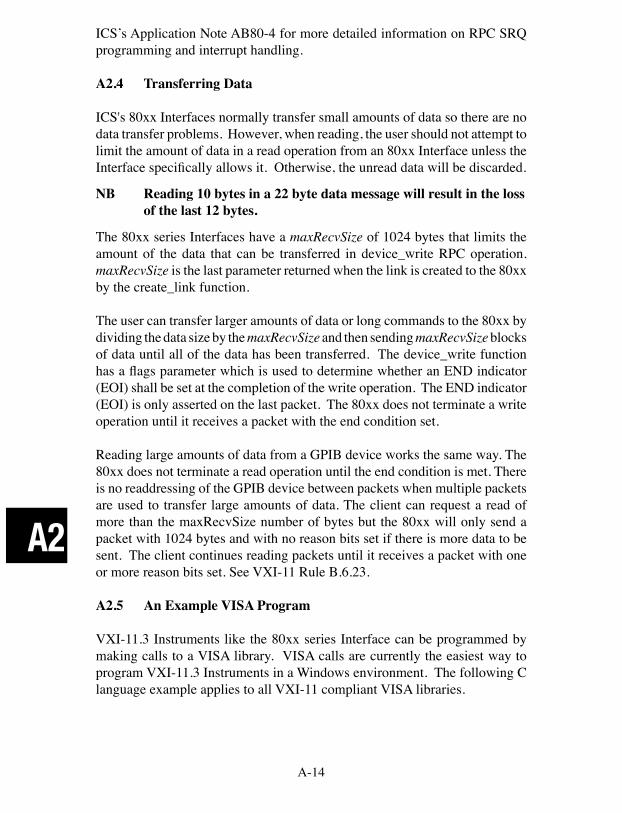
A-14
A2
ICS’s Application Note AB80-4 for more detailed information on RPC SRQ programming and interrupt handling.
A2.4 Transferring Data
ICS's 80xx Interfaces normally transfer small amounts of data so there are no data transfer problems. However, when reading, the user should not attempt to limit the amount of data in a read operation from an 80xx Interface unless the Interface specifically allows it. Otherwise, the unread data will be discarded.
NB Reading 10 bytes in a 22 byte data message will result in the loss of the last 12 bytes.
The 80xx series Interfaces have a maxRecvSize of 1024 bytes that limits the amount of the data that can be transferred in device_write RPC operation. maxRecvSize is the last parameter returned when the link is created to the 80xx by the create_link function.
The user can transfer larger amounts of data or long commands to the 80xx by dividing the data size by the maxRecvSize and then sending maxRecvSize blocks of data until all of the data has been transferred. The device_write function has a flags parameter which is used to determine whether an END indicator (EOI) shall be set at the completion of the write operation. The END indicator (EOI) is only asserted on the last packet. The 80xx does not terminate a write operation until it receives a packet with the end condition set.
Reading large amounts of data from a GPIB device works the same way. The 80xx does not terminate a read operation until the end condition is met. There is no readdressing of the GPIB device between packets when multiple packets are used to transfer large amounts of data. The client can request a read of more than the maxRecvSize number of bytes but the 80xx will only send a packet with 1024 bytes and with no reason bits set if there is more data to be sent. The client continues reading packets until it receives a packet with one or more reason bits set. See VXI-11 Rule B.6.23.
A2.5 An Example VISA Program
VXI-11.3 Instruments like the 80xx series Interface can be programmed by making calls to a VISA library. VISA calls are currently the easiest way to program VXI-11.3 Instruments in a Windows environment. The following C language example applies to all VXI-11 compliant VISA libraries.
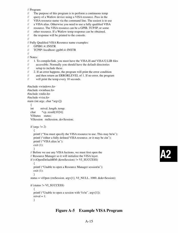
A-15
A2
// Program:// The purpose of this program is to perform a continuous temp// query of a Watlow device using a VISA resource. Pass in the// VISA resource name via the command line. The easiest is to use// a VISA alias. Otherwise you need to use a fully qualified VISA// resource. The VISA resource can be a GPIB, TCP/IP, or some// other resource. If a Watlow temp response can be obtained,// the response will be printed to the console.//// Fully Qualified VISA Resource name examples:// GPIB0::4::INSTR// TCPIP::localhost::gpib0,4::INSTR//// Notes:// 1. To compile/link, you must have the VISA.H and VISA32.LIB files// accessible. Normally you should have the default directories// setup to include these.// 2. If an error happens, the program will print the error condition// and then return an ERRORLEVEL of 1. If no error, the program// will print the temp every 10 seconds.
#include <windows.h>#include <winbase.h>#include <stdio.h>#include <visa.h>main (int argc, char *argv[]) { int retval, length, temp; char *cp, result[1024]; ViStatus status; ViSession rmSession, devSession;
if (argc != 2) { printf (“You must specify the VISA resource to use. This may be\n”); printf (“either a fully defined VISA resource, or it may be a\n”); printf (“VISA alias.\n”); exit (1); } // Before we use any VISA fuctions, we must first open the // Resource Manager so it will initialize the VISA layer. if (viOpenDefaultRM (&rmSession) != VI_SUCCESS) { printf (“Unable to open a Resource Manager session\n”); exit (1); } status = viOpen (rmSession, argv[1], VI_NULL, 1000, &devSession);
if (status != VI_SUCCESS) { printf (“Unable to open a session with %s\n”, argv[1]); retval = 1; }
Figure A-5 Example VISA Program

A-16
A2
else { for (;;) { status = viWrite (devSession, “R? 100,1”, 8, &length);
if (status != VI_SUCCESS) { printf (“Unable to send a temp query to %s\n”, argv[1]);
retval = 1; break; } else { status = viRead (devSession, result, sizeof(result), &length);
if (status != VI_SUCCESS) { printf (“Error reading the temp query response from %s\n”, argv[1]); retval = 1; break; } else { // Null terminate the received string since he viRead does not // auto-magically Null terminate the data. Note that this will // not remove the \n if one is included in the result string. result [length] = ‘\0’;
// If the result string contains a \n character, terminate the // string at that point - replacing the \n with a Null. cp = strchr (result, ‘\n’); if (cp) *cp = ‘\0’; // Convert the response to a tempature sscanf (result, “%d”, &temp);
printf (“Temp: %d.%d\r”, temp / 10, temp % 10);
// Now pause for 10 seconds Sleep (10 * 1000); } } } } // Close the Resource Manager now that we’re done with using VISA. viClose (rmSession); return (retval); }
Figure A-5 Example VISA Program Cont'd
A-17
A3
A3 VXI-11 RPC PROTOCOL
The information about the RPC Protocol in Section C is reprinted from the VXI-11 Specification. Consult the VXI-11 Specification for more information about using the VXI-11 RPC Protocol.
B. Basic RPC Programming
The following steps are the general steps to create an RPC program.
1. Obtain the man page for RPC on your system. If it is not available, confirm that you have RPC installed. Many systems do not have RPC installed since it is frequently considered an option. The man page gives an overview of RPC usage and will usually provide information on additional resources such as “rpcgen”.
2. Obtain the AB80-3 application note from the ICS website. Study this ap-plication note, but do understand that it is intended as an overview and is not detailed. In the summary section you will note several URL references for detailed RPC information. Skim through them to determine what information is available should it be needed.
3. Obtain the VXI-11 RPCL from either the last 2-3 pages of the VXI-11 base specification or from paragraph C in this Appendix. This needs to be copy/pasted into a text file which will be fed into the rpcgen utility.
4. Use your system's rpcgen tool to process the VXI-11 RPCL definition file you created in step-3. The result should be a .H and .C pair of files. These files will be used by your client application to perform VXI-11 functions.
5. Study the VXI-11 functions as defined in the VXI-11 specification. In par-ticular study the create_link, device_write and device_read. These are the core instructions required to do simple communication with a VXI-11 device.
6. Create a simple program to execute the following steps. Following the last step, you should have an IDN reply from the VXI-11 Device (80xx). The IDN reply provides an ASCII string defining the instrument model information.
a) Initialize the RPC layer. b) Execute a create_link to the 80xx c) Execute a device_write of “*IDN?” to the 80xx. d) Execute a device_read from the 80xx.
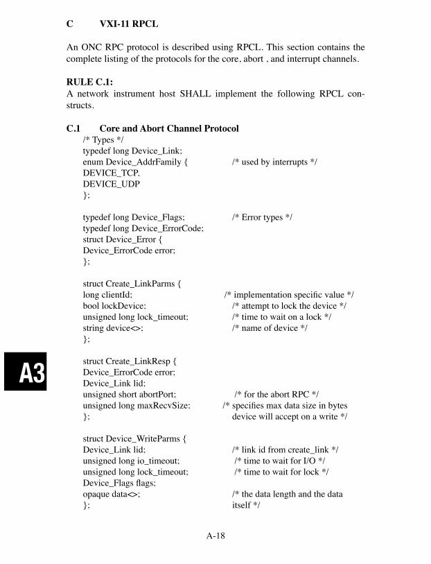
A-18
A3
C VXI-11 RPCL
An ONC RPC protocol is described using RPCL. This section contains the complete listing of the protocols for the core, abort , and interrupt channels.
RULE C.1:A network instrument host SHALL implement the following RPCL con-structs.
C.1 Core and Abort Channel Protocol/* Types */typedef long Device_Link;enum Device_AddrFamily { /* used by interrupts */DEVICE_TCP,DEVICE_UDP};
typedef long Device_Flags; /* Error types */typedef long Device_ErrorCode;struct Device_Error {Device_ErrorCode error;};
struct Create_LinkParms {long clientId; /* implementation specific value */bool lockDevice; /* attempt to lock the device */unsigned long lock_timeout; /* time to wait on a lock */string device<>; /* name of device */};
struct Create_LinkResp {Device_ErrorCode error;Device_Link lid;unsigned short abortPort; /* for the abort RPC */unsigned long maxRecvSize; /* specifies max data size in bytes}; device will accept on a write */
struct Device_WriteParms {Device_Link lid; /* link id from create_link */unsigned long io_timeout; /* time to wait for I/O */unsigned long lock_timeout; /* time to wait for lock */Device_Flags flags;opaque data<>; /* the data length and the data }; itself */
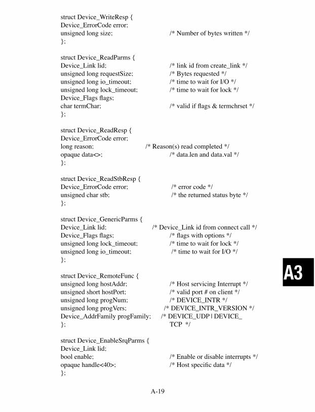
A-19
A3
struct Device_WriteResp {Device_ErrorCode error;unsigned long size; /* Number of bytes written */};
struct Device_ReadParms {Device_Link lid; /* link id from create_link */unsigned long requestSize; /* Bytes requested */unsigned long io_timeout; /* time to wait for I/O */unsigned long lock_timeout; /* time to wait for lock */Device_Flags flags;char termChar; /* valid if flags & termchrset */};
struct Device_ReadResp {Device_ErrorCode error;long reason; /* Reason(s) read completed */opaque data<>; /* data.len and data.val */};
struct Device_ReadStbResp {Device_ErrorCode error; /* error code */unsigned char stb; /* the returned status byte */};
struct Device_GenericParms {Device_Link lid; /* Device_Link id from connect call */Device_Flags flags; /* flags with options */unsigned long lock_timeout; /* time to wait for lock */unsigned long io_timeout; /* time to wait for I/O */};
struct Device_RemoteFunc {unsigned long hostAddr; /* Host servicing Interrupt */unsigned short hostPort; /* valid port # on client */unsigned long progNum; /* DEVICE_INTR */unsigned long progVers; /* DEVICE_INTR_VERSION */Device_AddrFamily progFamily; /* DEVICE_UDP | DEVICE_ }; TCP */ struct Device_EnableSrqParms {Device_Link lid;bool enable; /* Enable or disable interrupts */opaque handle<40>; /* Host specific data */};
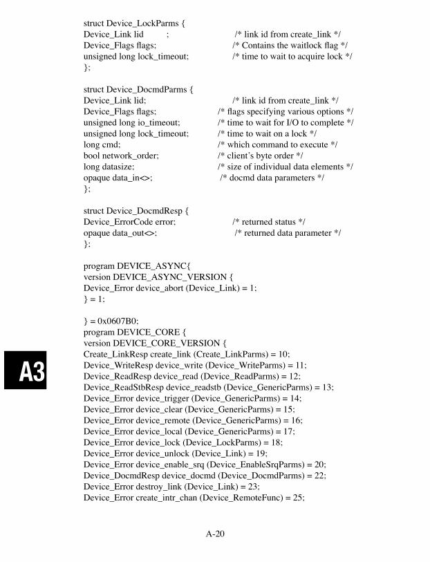
A-20
A3
struct Device_LockParms {Device_Link lid ; /* link id from create_link */Device_Flags flags; /* Contains the waitlock flag */unsigned long lock_timeout; /* time to wait to acquire lock */};
struct Device_DocmdParms {Device_Link lid; /* link id from create_link */Device_Flags flags; /* flags specifying various options */unsigned long io_timeout; /* time to wait for I/O to complete */unsigned long lock_timeout; /* time to wait on a lock */long cmd; /* which command to execute */bool network_order; /* client’s byte order */long datasize; /* size of individual data elements */opaque data_in<>; /* docmd data parameters */};
struct Device_DocmdResp {Device_ErrorCode error; /* returned status */opaque data_out<>; /* returned data parameter */};
program DEVICE_ASYNC{version DEVICE_ASYNC_VERSION {Device_Error device_abort (Device_Link) = 1;} = 1;
} = 0x0607B0;program DEVICE_CORE {version DEVICE_CORE_VERSION {Create_LinkResp create_link (Create_LinkParms) = 10;Device_WriteResp device_write (Device_WriteParms) = 11;Device_ReadResp device_read (Device_ReadParms) = 12;Device_ReadStbResp device_readstb (Device_GenericParms) = 13;Device_Error device_trigger (Device_GenericParms) = 14;Device_Error device_clear (Device_GenericParms) = 15;Device_Error device_remote (Device_GenericParms) = 16;Device_Error device_local (Device_GenericParms) = 17;Device_Error device_lock (Device_LockParms) = 18;Device_Error device_unlock (Device_Link) = 19;Device_Error device_enable_srq (Device_EnableSrqParms) = 20;Device_DocmdResp device_docmd (Device_DocmdParms) = 22;Device_Error destroy_link (Device_Link) = 23;Device_Error create_intr_chan (Device_RemoteFunc) = 25;
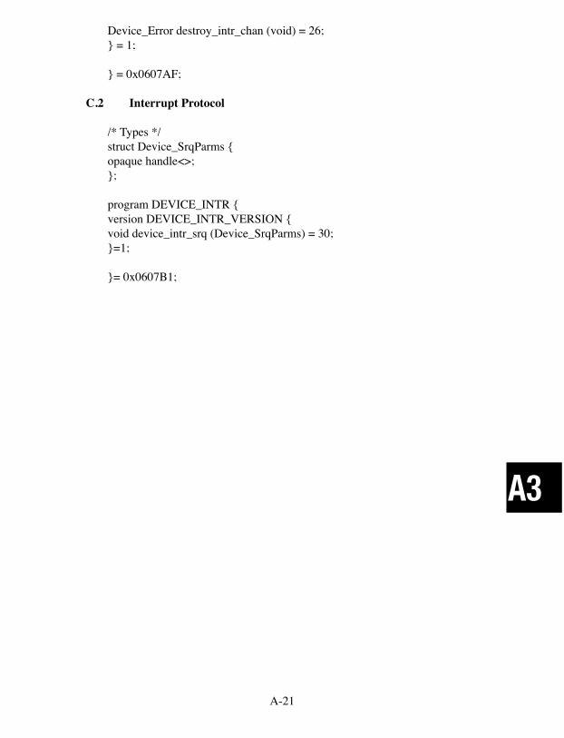
A-21
A3
Device_Error destroy_intr_chan (void) = 26;} = 1;
} = 0x0607AF;
C.2 Interrupt Protocol
/* Types */struct Device_SrqParms {opaque handle<>;};
program DEVICE_INTR {version DEVICE_INTR_VERSION {void device_intr_srq (Device_SrqParms) = 30;}=1;
}= 0x0607B1;
A-22
A4
A4 ICS CONFIGURATION RPC PROTOCOL
The following document describes ICS's Configuration RPC Protocol. This information is supplied to enable a RPC programmer to configure ICS 80xx devices that have an Ethernet interface with RPC commands.
A4.1 INTRODUCTION
This document defines the configuration interface to ICS 80xx devices (here-after referred to as the Edevice). The purpose of this document is to allow the communication between the controlling computer and the Edevice, for the purposes of modifying the operational characteristics of the Edevice. Edevices are ICS products whose Model number is in the 80xx range. Note that not all commands are supported by all Edevices.
A4.2 SCOPE
This specification addresses the Edevice communication for the purposes of operational configuration.
This specification is to be considered an addendum to the VXI-11 specifica-tion for communication to the VXI-11 compliant ICS Edevice Interfaces. The Edevice follows the VXI-11.2 and/or VXI-11.3 specifications.
It is assumed the reader is conversant with ONC/RPC and XDR specifications as published by Sun Microsystems. All client/Edevice communication is per-formed through ONC/RPC and thus requires knowledge of both (ONC/RPC and XDR) specifications. In addition, it is assumed the reader is conversant with the VXI-11 and VXI-11.2 specifications as published by the VXIbus Con-sortium. In some cases, the reader will require an understanding of the GPIB (IEEE-488) specification as published in the IEEE Standards.
A4.3 SPECIFICATION OBJECTIVES
This specification has the following objectives:1. To enable the creation of tools to perform Edevice configuration.2. To enable applications to perform temporary modifications to the Edevice configuration.3. To define the ONC/RPC protocol used by the Edevice configuration.
A-23
A4
A4.4 REFERENCES
[1] IEEE Std 488.1-1987, IEEE Standard Digital Interface for Programmable Instrumentation.[2] IEEE Std 488.2-1992, IEEE Standard Codes, Formats, Protocols, and Com-mon Commands For Use With IEEE Std 488.1-1987, IEEE Standard Digital Interface for Programmable Instrumentation.[3] XDR: External Data Representation Standard, Request for Comments 1014, Sun Microsystems, DDN Network Information Center, SRI International, June, 1987.[4] RPC: Remote Procedure Call Protocol Specification, Request for Com-ments, 1057, Sun Microsystems, DDN Network Information Center, SRI International, June, 1988.
B EDEVICE CONFIGURATION PROTOCOL
The Edevice Configuration protocol uses the ONC remote procedure call (RPC) model. This model allows an application executing on one computer to conceptually call a function on another computer.
The client identifies the remote procedure by means of a program ID, program version, and procedure number. This information is encoded into an RPC com-munication packet with the procedure argument values. The message is then sent to the RPC service running on the server device, where the target procedure is then executed. The server is required to respond to all procedure calls with an RPC reply message containing any/all procedure return values.
Table B.1 lists the RPC messages used by the Edevice configuration protocol. Messages that apply to a specific 80xx device are marked by an 'x' in the 80xx device column. Section C provides detailed descriptions of each Configuration Message. Section D provides a summary RPCL listing for use with rpcgen utilities.
B.1 PROTOCOL BEHAVIOR
The client shall issue an RPC command to the Edevice directing the action to be taken. The Edevice shall attempt to execute the action and will then reply with an RPC reply.
All configuration messages pertaining to values or modes shall contain an Ac-tion boolean indicating whether the action is to be a read of the current setting or a modification of the current setting. Edevice default values are listed in Section 1 of this manual.
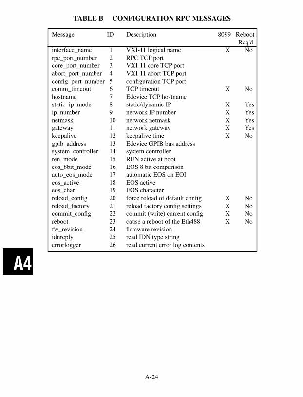
A-24
A4
TABLE B CONFIGURATION RPC MESSAGES
Message ID Description 8099 Reboot Req'dinterface_name 1 VXI-11 logical name X Norpc_port_number 2 RPC TCP port core_port_number 3 VXI-11 core TCP port abort_port_number 4 VXI-11 abort TCP port config_port_number 5 configuration TCP port comm_timeout 6 TCP timeout X Nohostname 7 Edevice TCP hostnamestatic_ip_mode 8 static/dynamic IP X Yesip_number 9 network IP number X Yesnetmask 10 network netmask X Yesgateway 11 network gateway X Yeskeepalive 12 keepalive time X Nogpib_address 13 Edevice GPIB bus address system_controller 14 system controller ren_mode 15 REN active at boot eos_8bit_mode 16 EOS 8 bit comparison auto_eos_mode 17 automatic EOS on EOI eos_active 18 EOS active eos_char 19 EOS character reload_config 20 force reload of default config X Noreload_factory 21 reload factory config settings X Nocommit_config 22 commit (write) current config X Noreboot 23 cause a reboot of the Eth488 X Nofw_revision 24 firmware revision idnreply 25 read IDN type string errorlogger 26 read current error log contents

A-25
A4
All configuration messages pertaining to actions shall respond with an RPC reply and then (if the status is No Error) execute the action.
All Edevice configuration commands will reply with statuses corresponding to Error Codes as defined by the VXI-11 (section B.5.2).
All Edevice configuration command data will use XDR encoding. Numeri-cal values will be of 4-byte unsigned integer format. String and binary fields will be of opaque array format. Variable length string values will be NULL terminated and will contain a leading length numerical value defining the total length (inclusive of the NULL).
All Edevice configuration commands and replies will result in RPC messages which are multiples of 4-byte lengths. Padding will occur following the last data field and may consist of any byte value.
When the Action boolean signals a read of a mode/value setting, the RPC com-mand must contain a dummy mode/value. While the mode/value in the RPC command is not used, it must exist. If the mode/value is not contained within the RPC command, an error status will result.
The successful modification of a configuration setting will result in the change taking effect immediately, except where noted. Thus, it is strongly advisable to not make configuration changes if VXI-11 device links are currently active. Doing so can cause unpredictable results and Edevice misbehavior. However, such dynamic modifications may be desirable and are possible at the discre-tion of the user. Messages that require rebooting will not take affect until the Edevice is rebooted.
B.2 Edevice PROGRAM ID AND VERSION
The Edevice configuration procedures shall use an RPC program ID of 1515151515 and an RPC version number of 1.
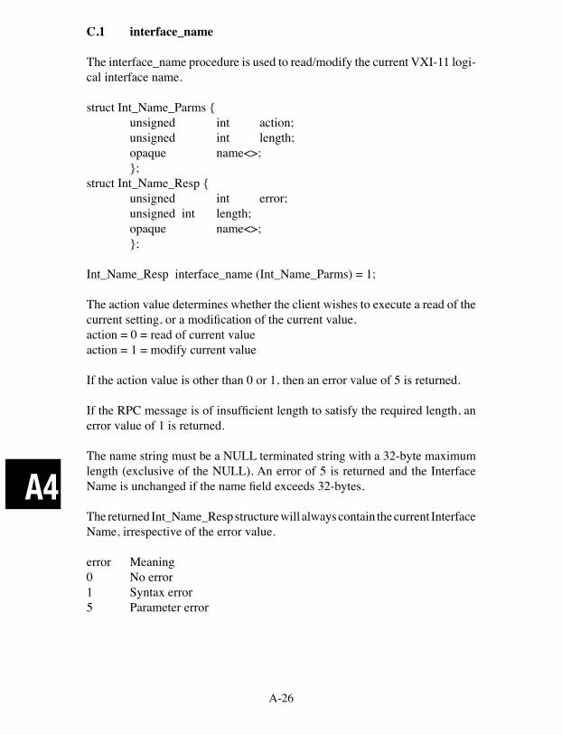
A-26
A4
C.1 interface_name
The interface_name procedure is used to read/modify the current VXI-11 logi-cal interface name.
struct Int_Name_Parms { unsigned int action; unsigned int length; opaque name<>; };struct Int_Name_Resp { unsigned int error; unsigned int length; opaque name<>; };
Int_Name_Resp interface_name (Int_Name_Parms) = 1;
The action value determines whether the client wishes to execute a read of the current setting, or a modification of the current value.action = 0 = read of current valueaction = 1 = modify current value
If the action value is other than 0 or 1, then an error value of 5 is returned.
If the RPC message is of insufficient length to satisfy the required length, an error value of 1 is returned.
The name string must be a NULL terminated string with a 32-byte maximum length (exclusive of the NULL). An error of 5 is returned and the Interface Name is unchanged if the name field exceeds 32-bytes.
The returned Int_Name_Resp structure will always contain the current Interface Name, irrespective of the error value.
error Meaning0 No error1 Syntax error5 Parameter error

A-27
A4
C.2 rpc_port_number
The rpc_port_number procedure is used to read/modify the TCP port used by the RPC server.
struct Rpc_Port_Parms { unsigned int action; unsigned int port; };struct Rpc_Port_Resp { unsigned int error; unsigned int port; };
Rpc_Port_Resp rpc_port_number (Rpc_Port_Parms) = 2;
The action value determines whether the client wishes to execute a read of the current setting, or a modification of the current value.action = 0 = read of current valueaction = 1 = modify current value
If the action value is other than 0 or 1, then an error value of 5 is returned.
If the RPC message is of insufficient length to satisfy the required length, an error value of 1 is returned.
The port value must be within the range of 0x0001 and 0xFFFF. An error of 5 is returned and the RPC Port value is unchanged if the port value is outside of this range.
The returned Rpc_Port_Resp structure will always contain the current RPC Port value, irrespective of the error value.
error Meaning0 No error1 Syntax error5 Parameter error
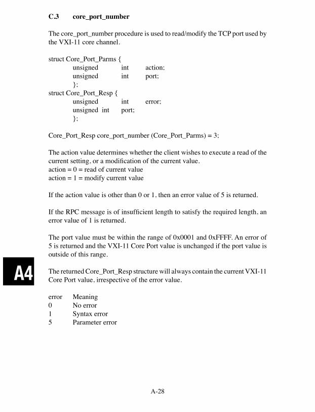
A-28
A4
C.3 core_port_number
The core_port_number procedure is used to read/modify the TCP port used by the VXI-11 core channel.
struct Core_Port_Parms { unsigned int action; unsigned int port; };struct Core_Port_Resp { unsigned int error; unsigned int port; };
Core_Port_Resp core_port_number (Core_Port_Parms) = 3;
The action value determines whether the client wishes to execute a read of the current setting, or a modification of the current value.action = 0 = read of current valueaction = 1 = modify current value
If the action value is other than 0 or 1, then an error value of 5 is returned.
If the RPC message is of insufficient length to satisfy the required length, an error value of 1 is returned.
The port value must be within the range of 0x0001 and 0xFFFF. An error of 5 is returned and the VXI-11 Core Port value is unchanged if the port value is outside of this range.
The returned Core_Port_Resp structure will always contain the current VXI-11 Core Port value, irrespective of the error value.
error Meaning0 No error1 Syntax error5 Parameter error
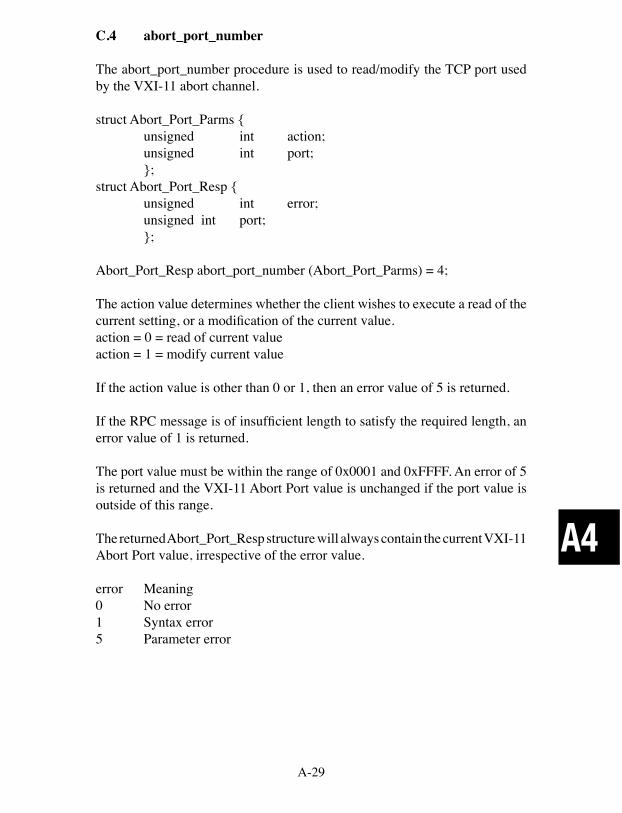
A-29
A4
C.4 abort_port_number
The abort_port_number procedure is used to read/modify the TCP port used by the VXI-11 abort channel.
struct Abort_Port_Parms { unsigned int action; unsigned int port; };struct Abort_Port_Resp { unsigned int error; unsigned int port; };
Abort_Port_Resp abort_port_number (Abort_Port_Parms) = 4;
The action value determines whether the client wishes to execute a read of the current setting, or a modification of the current value.action = 0 = read of current valueaction = 1 = modify current value
If the action value is other than 0 or 1, then an error value of 5 is returned.
If the RPC message is of insufficient length to satisfy the required length, an error value of 1 is returned.
The port value must be within the range of 0x0001 and 0xFFFF. An error of 5 is returned and the VXI-11 Abort Port value is unchanged if the port value is outside of this range.
The returned Abort_Port_Resp structure will always contain the current VXI-11 Abort Port value, irrespective of the error value.
error Meaning0 No error1 Syntax error5 Parameter error

A-30
A4
C.5 config_port_number
The config_port_number procedure is used to read/modify the TCP port used by the Edevice configuration channel.
struct Config_Port_Parms { unsigned int action; unsigned int port; };struct Config_Port_Resp { unsigned int error; unsigned int port; };
Config_Port_Resp config_port_number (Config_Port_Parms) = 5;
The action value determines whether the client wishes to execute a read of the current setting, or a modification of the current value.action = 0 = read of current valueaction = 1 = modify current value
If the action value is other than 0 or 1, then an error value of 5 is returned.
If the RPC message is of insufficient length to satisfy the required length, an error value of 1 is returned.
The port value must be within the range of 0x0001 and 0xFFFF. An error of 5 is returned and the VXI-11 Abort Port value is unchanged if the port value is outside of this range.
The returned Configt_Port_Resp structure will always contain the current VXI-11 Abort Port value, irrespective of the error value.
error Meaning0 No error1 Syntax error5 Parameter error
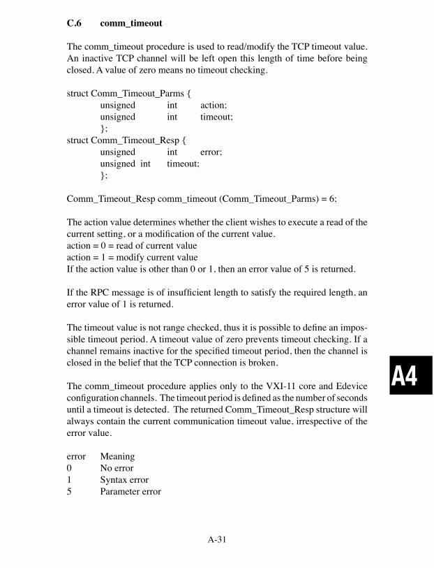
A-31
A4
C.6 comm_timeout
The comm_timeout procedure is used to read/modify the TCP timeout value. An inactive TCP channel will be left open this length of time before being closed. A value of zero means no timeout checking.
struct Comm_Timeout_Parms { unsigned int action; unsigned int timeout; };struct Comm_Timeout_Resp { unsigned int error; unsigned int timeout; };
Comm_Timeout_Resp comm_timeout (Comm_Timeout_Parms) = 6;
The action value determines whether the client wishes to execute a read of the current setting, or a modification of the current value.action = 0 = read of current valueaction = 1 = modify current valueIf the action value is other than 0 or 1, then an error value of 5 is returned.
If the RPC message is of insufficient length to satisfy the required length, an error value of 1 is returned.
The timeout value is not range checked, thus it is possible to define an impos-sible timeout period. A timeout value of zero prevents timeout checking. If a channel remains inactive for the specified timeout period, then the channel is closed in the belief that the TCP connection is broken.
The comm_timeout procedure applies only to the VXI-11 core and Edevice configuration channels. The timeout period is defined as the number of seconds until a timeout is detected. The returned Comm_Timeout_Resp structure will always contain the current communication timeout value, irrespective of the error value.
error Meaning0 No error1 Syntax error5 Parameter error
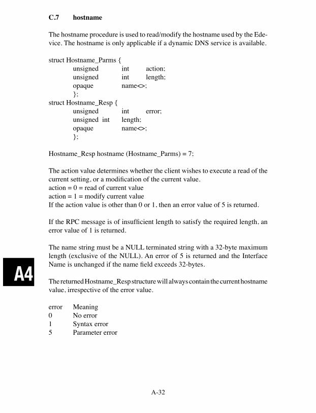
A-32
A4
C.7 hostname
The hostname procedure is used to read/modify the hostname used by the Ede-vice. The hostname is only applicable if a dynamic DNS service is available.
struct Hostname_Parms { unsigned int action; unsigned int length; opaque name<>; };struct Hostname_Resp { unsigned int error; unsigned int length; opaque name<>; };
Hostname_Resp hostname (Hostname_Parms) = 7;
The action value determines whether the client wishes to execute a read of the current setting, or a modification of the current value.action = 0 = read of current valueaction = 1 = modify current valueIf the action value is other than 0 or 1, then an error value of 5 is returned.
If the RPC message is of insufficient length to satisfy the required length, an error value of 1 is returned.
The name string must be a NULL terminated string with a 32-byte maximum length (exclusive of the NULL). An error of 5 is returned and the Interface Name is unchanged if the name field exceeds 32-bytes.
The returned Hostname_Resp structure will always contain the current hostname value, irrespective of the error value.
error Meaning0 No error1 Syntax error5 Parameter error

A-33
A4
C.8 static_ip_mode
The static_ip_mode procedure is used to read/modify the static IP mode. If static_ip_mode is set TRUE, then the Edevice will use a static IP and will need a netmask and gateway IP.
struct Static_IP_Parms { unsigned int action; unsigned int mode; };struct Static_IP_Resp { unsigned int error; unsigned int mode; };
Static_IP_Resp static_ip_mode (Static_IP_Parms) = 8;
The action value determines whether the client wishes to execute a read of the current setting, or a modification of the current value.action = 0 = read of current valueaction = 1 = modify current value
If the action value is other than 0 or 1, then an error value of 5 is returned.
If the RPC message is of insufficient length to satisfy the required length, an error value of 1 is returned.
The mode must be either 0 (dynamic) or 1 (static). An error of 5 is returned and the static IP mode is unchanged if the mode field is any other value.
The returned Static_IP_Resp structure will always contain the current static IP mode, irrespective of the error value.
error Meaning0 No error1 Syntax error5 Parameter error
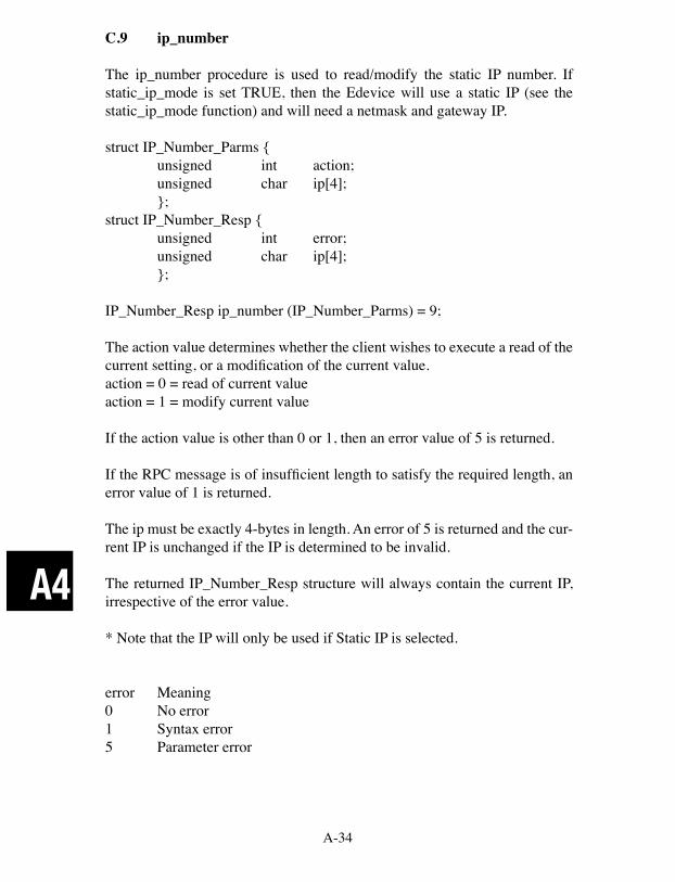
A-34
A4
C.9 ip_number
The ip_number procedure is used to read/modify the static IP number. If static_ip_mode is set TRUE, then the Edevice will use a static IP (see the static_ip_mode function) and will need a netmask and gateway IP.
struct IP_Number_Parms { unsigned int action; unsigned char ip[4]; };struct IP_Number_Resp { unsigned int error; unsigned char ip[4]; };
IP_Number_Resp ip_number (IP_Number_Parms) = 9;
The action value determines whether the client wishes to execute a read of the current setting, or a modification of the current value.action = 0 = read of current valueaction = 1 = modify current value
If the action value is other than 0 or 1, then an error value of 5 is returned.
If the RPC message is of insufficient length to satisfy the required length, an error value of 1 is returned.
The ip must be exactly 4-bytes in length. An error of 5 is returned and the cur-rent IP is unchanged if the IP is determined to be invalid.
The returned IP_Number_Resp structure will always contain the current IP, irrespective of the error value.
* Note that the IP will only be used if Static IP is selected.
error Meaning0 No error1 Syntax error5 Parameter error

A-35
A4
C.10 netmask
The netmask procedure is used to read/modify the netmask. If static_ip_mode is set TRUE, then the Edevice will use a static IP (see the static_ip_mode func-tion) and will need a netmask and gateway IP.
struct Netmask_Parms { unsigned int action; unsigned char netmask[4]; };struct Netmask_Resp { unsigned int error; unsigned char netmask[4]; };
Netmask_Resp netmask (Netmask_Parms) = 10;
The action value determines whether the client wishes to execute a read of the current setting, or a modification of the current value.action = 0 = read of current valueaction = 1 = modify current value
If the action value is other than 0 or 1, then an error value of 5 is returned.
If the RPC message is of insufficient length to satisfy the required length, an error value of 1 is returned.The netmask must be exactly 4-bytes in length. An error of 5 is returned and the current netmask is unchanged if the netmask is determined to be invalid.The returned Netmask_Resp structure will always contain the current netmask, irrespective of the error value.
* Note that the IP will only be used if Static IP is selected.
error Meaning0 No error1 Syntax error5 Parameter error
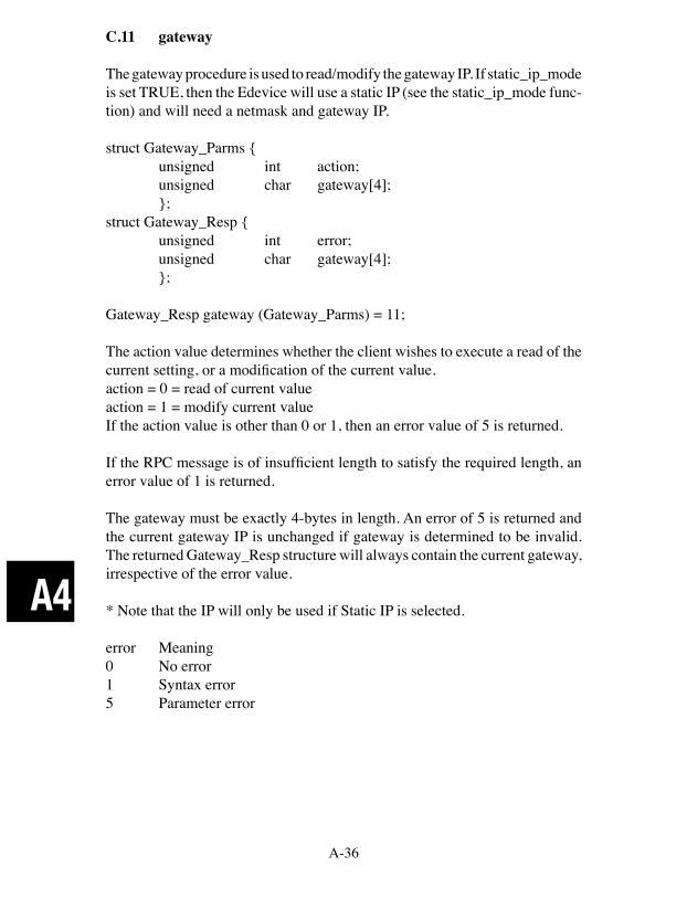
A-36
A4
C.11 gateway
The gateway procedure is used to read/modify the gateway IP. If static_ip_mode is set TRUE, then the Edevice will use a static IP (see the static_ip_mode func-tion) and will need a netmask and gateway IP.
struct Gateway_Parms { unsigned int action; unsigned char gateway[4]; };struct Gateway_Resp { unsigned int error; unsigned char gateway[4]; };
Gateway_Resp gateway (Gateway_Parms) = 11;
The action value determines whether the client wishes to execute a read of the current setting, or a modification of the current value.action = 0 = read of current valueaction = 1 = modify current valueIf the action value is other than 0 or 1, then an error value of 5 is returned.
If the RPC message is of insufficient length to satisfy the required length, an error value of 1 is returned.
The gateway must be exactly 4-bytes in length. An error of 5 is returned and the current gateway IP is unchanged if gateway is determined to be invalid. The returned Gateway_Resp structure will always contain the current gateway, irrespective of the error value.
* Note that the IP will only be used if Static IP is selected.
error Meaning0 No error1 Syntax error5 Parameter error
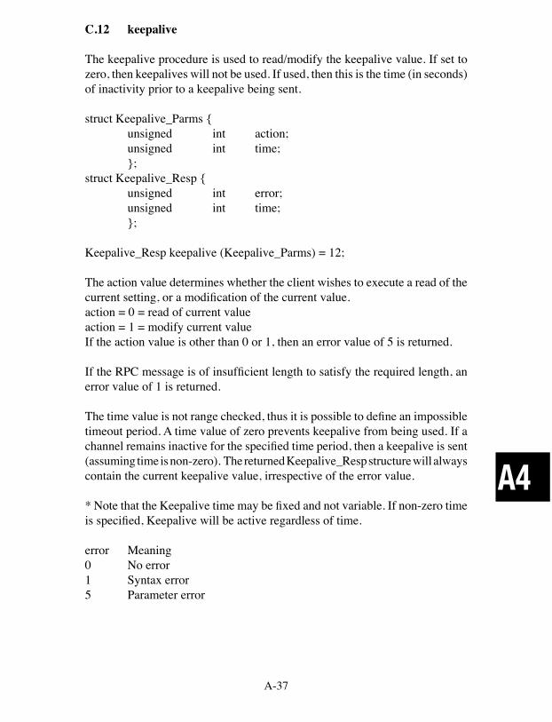
A-37
A4
C.12 keepalive
The keepalive procedure is used to read/modify the keepalive value. If set to zero, then keepalives will not be used. If used, then this is the time (in seconds) of inactivity prior to a keepalive being sent.
struct Keepalive_Parms { unsigned int action; unsigned int time; };struct Keepalive_Resp { unsigned int error; unsigned int time; };
Keepalive_Resp keepalive (Keepalive_Parms) = 12;
The action value determines whether the client wishes to execute a read of the current setting, or a modification of the current value.action = 0 = read of current valueaction = 1 = modify current valueIf the action value is other than 0 or 1, then an error value of 5 is returned.
If the RPC message is of insufficient length to satisfy the required length, an error value of 1 is returned.
The time value is not range checked, thus it is possible to define an impossible timeout period. A time value of zero prevents keepalive from being used. If a channel remains inactive for the specified time period, then a keepalive is sent (assuming time is non-zero). The returned Keepalive_Resp structure will always contain the current keepalive value, irrespective of the error value.
* Note that the Keepalive time may be fixed and not variable. If non-zero time is specified, Keepalive will be active regardless of time.
error Meaning0 No error1 Syntax error5 Parameter error
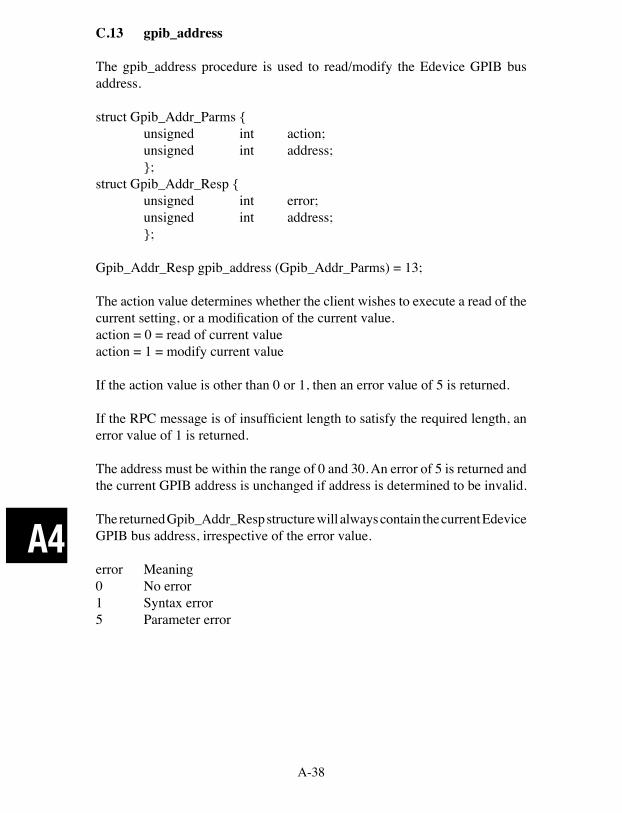
A-38
A4
C.13 gpib_address
The gpib_address procedure is used to read/modify the Edevice GPIB bus address.
struct Gpib_Addr_Parms { unsigned int action; unsigned int address; };struct Gpib_Addr_Resp { unsigned int error; unsigned int address; };
Gpib_Addr_Resp gpib_address (Gpib_Addr_Parms) = 13;
The action value determines whether the client wishes to execute a read of the current setting, or a modification of the current value.action = 0 = read of current valueaction = 1 = modify current value
If the action value is other than 0 or 1, then an error value of 5 is returned.
If the RPC message is of insufficient length to satisfy the required length, an error value of 1 is returned.
The address must be within the range of 0 and 30. An error of 5 is returned and the current GPIB address is unchanged if address is determined to be invalid.
The returned Gpib_Addr_Resp structure will always contain the current Edevice GPIB bus address, irrespective of the error value.
error Meaning0 No error1 Syntax error5 Parameter error

A-39
A4
C.14 system_controller
The system_controller procedure is used to read/modify the system controller mode. If the system controller mode is set TRUE, then the Edevice will initial-ize at boot time as the GPIB bus controller.
struct Sys_Control_Parms { unsigned int action; unsigned int controller; };struct Sys_Control_Resp { unsigned int error; unsigned int controller; };
Sys_Control_Resp system_controller (Sys_Control_Parms) = 14;
The action value determines whether the client wishes to execute a read of the current setting, or a modification of the current value.action = 0 = read of current valueaction = 1 = modify current valueIf the action value is other than 0 or 1, then an error value of 5 is returned.
If the RPC message is of insufficient length to satisfy the required length, an error value of 1 is returned.
The controller mode must be either 0 or 1. An error of 5 is returned and the current system controller mode is unchanged if controller is determined to be invalid.
The returned Sys_Control_Resp structure will always contain the current system controller mode, irrespective of the error value.
error Meaning0 No error1 Syntax error5 Parameter error
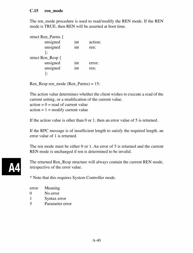
A-40
A4
C.15 ren_mode
The ren_mode procedure is used to read/modify the REN mode. If the REN mode is TRUE, then REN will be asserted at boot time.
struct Ren_Parms { unsigned int action; unsigned int ren; };struct Ren_Resp { unsigned int error; unsigned int ren; };
Ren_Resp ren_mode (Ren_Parms) = 15;
The action value determines whether the client wishes to execute a read of the current setting, or a modification of the current value.action = 0 = read of current valueaction = 1 = modify current value
If the action value is other than 0 or 1, then an error value of 5 is returned.
If the RPC message is of insufficient length to satisfy the required length, an error value of 1 is returned.
The ren mode must be either 0 or 1. An error of 5 is returned and the current REN mode is unchanged if ren is determined to be invalid.
The returned Ren_Resp structure will always contain the current REN mode, irrespective of the error value.
* Note that this requires System Controller mode.
error Meaning0 No error1 Syntax error5 Parameter error

A-41
A4
C.16 eos_8bit_mode
The eos_8bit_mode procedure is used to read/modify the 8-bit EOS compare mode. If the 8-bit compare mode is TRUE, then EOS compare will be 8-bits. If 8-bit compare mode is FALSE, then EOS compare will be 7-bits.
struct Eos_8bit_Parms { unsigned int action; unsigned int eos8bit; };struct Eos_8bit_Resp { unsigned int error; unsigned int eos8bit; };
Eos_8bit_Resp eos_8bit_mode (Eos_8bit_Parms) = 16;
The action value determines whether the client wishes to execute a read of the current setting, or a modification of the current value.action = 0 = read of current valueaction = 1 = modify current valueIf the action value is other than 0 or 1, then an error value of 5 is returned.
If the RPC message is of insufficient length to satisfy the required length, an error value of 1 is returned.
The eos8bit mode must be either 0 or 1. An error of 5 is returned and the current 8-bit EOS compare mode is unchanged if eos8bit is determined to be invalid.
The returned Eos_8bit_Resp structure will always contain the current 8-bit EOS compare mode, irrespective of the error value.
error Meaning0 No error1 Syntax error5 Parameter error
C.17 auto_eos_mode
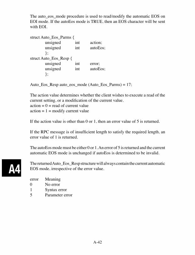
A-42
A4
The auto_eos_mode procedure is used to read/modify the automatic EOS on EOI mode. If the autoEos mode is TRUE, then an EOS character will be sent with EOI.
struct Auto_Eos_Parms { unsigned int action; unsigned int autoEos; };struct Auto_Eos_Resp { unsigned int error; unsigned int autoEos; };
Auto_Eos_Resp auto_eos_mode (Auto_Eos_Parms) = 17;
The action value determines whether the client wishes to execute a read of the current setting, or a modification of the current value.action = 0 = read of current valueaction = 1 = modify current value
If the action value is other than 0 or 1, then an error value of 5 is returned.
If the RPC message is of insufficient length to satisfy the required length, an error value of 1 is returned.
The autoEos mode must be either 0 or 1. An error of 5 is returned and the current automatic EOS mode is unchanged if autoEos is determined to be invalid.
The returned Auto_Eos_Resp structure will always contain the current automatic EOS mode, irrespective of the error value.
error Meaning0 No error1 Syntax error5 Parameter error

A-43
A4
C.18 eos_active_mode
The eos_active_mode procedure is used to read/modify the EOS active mode. If the EOS mode is TRUE, then an EOS character will terminate reads.
struct Eos_Active_Parms { unsigned int action; unsigned int eosActive; };struct Eos_Active_Resp { unsigned int error; unsigned int eosActive; };
EosActive_Resp eos_active_mode (Eos_Active_Parms) = 18;
The action value determines whether the client wishes to execute a read of the current setting, or a modification of the current value.action = 0 = read of current valueaction = 1 = modify current value
If the action value is other than 0 or 1, then an error value of 5 is returned.
If the RPC message is of insufficient length to satisfy the required length, an error value of 1 is returned.
The eosActive mode must be either 0 or 1. An error of 5 is returned and the current automatic EOS mode is unchanged if eosActive is determined to be invalid.
The returned Eos_Active_Resp structure will always contain the current EOS mode, irrespective of the error value.
error Meaning0 No error1 Syntax error5 Parameter error
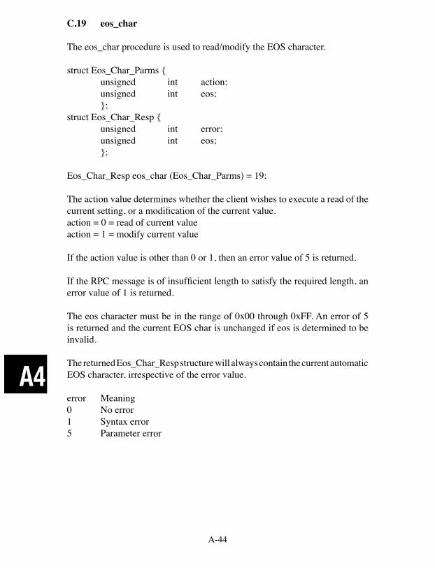
A-44
A4
C.19 eos_char
The eos_char procedure is used to read/modify the EOS character.
struct Eos_Char_Parms { unsigned int action; unsigned int eos; };struct Eos_Char_Resp { unsigned int error; unsigned int eos; };
Eos_Char_Resp eos_char (Eos_Char_Parms) = 19;
The action value determines whether the client wishes to execute a read of the current setting, or a modification of the current value.action = 0 = read of current valueaction = 1 = modify current value
If the action value is other than 0 or 1, then an error value of 5 is returned.
If the RPC message is of insufficient length to satisfy the required length, an error value of 1 is returned.
The eos character must be in the range of 0x00 through 0xFF. An error of 5 is returned and the current EOS char is unchanged if eos is determined to be invalid.
The returned Eos_Char_Resp structure will always contain the current automatic EOS character, irrespective of the error value.
error Meaning0 No error1 Syntax error5 Parameter error
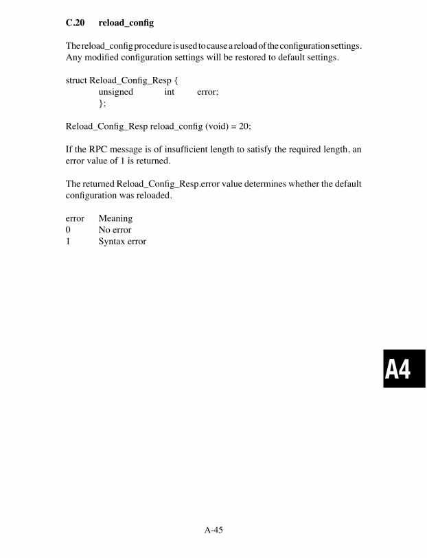
A-45
A4
C.20 reload_config
The reload_config procedure is used to cause a reload of the configuration settings. Any modified configuration settings will be restored to default settings.
struct Reload_Config_Resp { unsigned int error; };
Reload_Config_Resp reload_config (void) = 20;
If the RPC message is of insufficient length to satisfy the required length, an error value of 1 is returned.
The returned Reload_Config_Resp.error value determines whether the default configuration was reloaded.
error Meaning0 No error1 Syntax error
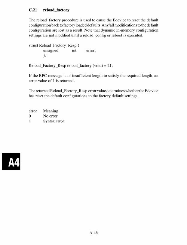
A-46
A4
C.21 reload_factory
The reload_factory procedure is used to cause the Edevice to reset the default configuration back to factory loaded defaults. Any/all modifications to the default configuration are lost as a result. Note that dynamic in-memory configuration settings are not modified until a reload_config or reboot is executed.
struct Reload_Factory_Resp { unsigned int error; };
Reload_Factory_Resp reload_factory (void) = 21;
If the RPC message is of insufficient length to satisfy the required length, an error value of 1 is returned.
The returned Reload_Factory_Resp.error value determines whether the Edevice has reset the default configurations to the factory default settings.
error Meaning0 No error1 Syntax error

A-47
A4
C.22 commit_config
The commit_config procedure is used to cause the current configuration set-tings to be saved. Any modified configuration settings now become default settings and will be reloaded as the default settings with either reload_config or a reboot.
struct Commit_Config_Resp { unsigned int error; };
Commit_Config_Resp commit_config (void) = 22;
If the RPC message is of insufficient length to satisfy the required length, an error value of 1 is returned.
The returned Commit_Config_Resp.error value determines whether the current configuration was saved as the default configuration.
error Meaning0 No error1 Syntax error
A-48
A4
C.23 Reboot
The Reboot procedure is used to cause the Edevice to reboot. This causes all device links to be cleared, all connections closed, all resources released, and the default configuration to be loaded and used during initialization.
struct reboot_Resp { unsigned int error; };
reboot_Resp reboot (void) = 23;
If the RPC message is of insufficient length to satisfy the required length, an error value of 1 is returned.
The returned Reboot_Resp.error value determines whether the Edevice has initiated a reboot process. Note that the timing of the reboot process may block the RPC reply.
* Note that certain configuration settings are only set at boot time. Thus when setting configuration settings, it is recommended that the Reboot command always terminates the configuration setting.
error Meaning0 No error1 Syntax error
A-49
A4
C.24 idnReply
The idnReply procedure is used to obtain a response similar to the GPIB *IDN? string. It contains the FW revision, the ICS product model number, and other miscellaneous information.
struct Idn_Parms { };struct Idn_Resp { unsigned int error; opaque idn<>; };
idn_resp idnreply (idn_Parms) = 25;
Error Meaning0 No error
A-50
A4
C.25 errorLogger
The errorLogger procedure is used to obtain the current contents of the error log.
struct error_log_Parms { };struct Error_Log_Resp { unsigned int error; unsigned int count; unsigned int errors[100]; };
error_log_Resp errorlogger (error_log_Parms) = 26;
The error log will contain 100 entries. The count will signify how many are valid. The remaining values will be of indeterminate values.
Note this function returns all entries and flushes the error log. Do not run this function more than 5 times per second to avoid impacting the 8065's perfor-mance and overloading the network.
Refer to the ErrorLogger utility for the error value definitions.
Error Meaning0 No error
A-51
A4
D RPCL Listing
The following is a summary listing of ICS's EDevice Configuration RPC Messages.
/* IP-note: 4-byte IP’s are packed into a 32 bit unsigned integer in * reverse network byte order. XDR integers are in host byte order. */
/* Action parameter values */%#define ICS_READ 0%#define ICS_WRITE 1
/* The interface_name procedure is used to read/modify the current VXI-11 * logical interface name. */struct Int_Name_Parms { unsigned int action; opaque name<>;};struct Int_Name_Resp { unsigned int error; opaque name<>;};
/* The rpc_port_number procedure is used to read/modify the TCP port used * by the RPC server. */struct Rpc_Port_Parms { unsigned int action; unsigned int port;};struct Rpc_Port_Resp { unsigned int error; unsigned int port;};
/* The core_port_number procedure is used to read/modify the TCP port * used by the VXI-11 core channel. */struct Core_Port_Parms { unsigned int action; unsigned int port;};
A-52
A4
struct Core_Port_Resp { unsigned int error; unsigned int port;};
/* The abort_port_number procedure is used to read/modify the TCP port * used by the VXI-11 abort channel. */struct Abort_Port_Parms { unsigned int action; unsigned int port;};struct Abort_Port_Resp { unsigned int error; unsigned int port;};
/* The config_port_number procedure is used to read/modify the TCP port * used by the Edevice configuration channel. */struct Config_Port_Parms { unsigned int action; unsigned int port;};struct Config_Port_Resp { unsigned int error; unsigned int port;};
/* The comm_timeout procedure is used to read/modfiy the TCP timeout value. * An inactive TCP channel will be left open this length of time before * being closed. A value of zero means no timeout checking. */struct Comm_Timeout_Parms { unsigned int action; unsigned int timeout;};struct Comm_Timeout_Resp { unsigned int error; unsigned int timeout;};
A-53
A4
/* The hostname procedure is used to read/modify the hostname used by the * Edevice. The hostname is only applicable if a dynamic DNS service is * available. */struct Hostname_Parms { unsigned int action; opaque name<>;};struct Hostname_Resp { unsigned int error; opaque name<>;};
/* The static_ip_mode procedure is used to read/modify the static IP mode. * If static_ip_mode is set TRUE, then the Edevice will use a static IP * and will need a netmask and gateway IP. */struct Static_IP_Parms { unsigned int action; unsigned int mode;};struct Static_IP_Resp { unsigned int error; unsigned int mode;};
/* The ip_number procedure is used to read/modify the static IP number. * If static_ip_mode is set TRUE, then the Edevice will use a static IP * (see the static_ip_mode function) and will need a netmask and gateway IP. */struct IP_Number_Parms { unsigned int action; unsigned int ip; /* see IP-note above */};struct IP_Number_Resp { unsigned int error; unsigned int ip; /* see IP-note above */};
/* The netmask procedure is used to read/modify the netmask. * If static_ip_mode is set TRUE, then the Edevice will use a static IP * (see the static_ip_mode function) and will need a netmask and gateway IP. */

A-54
A4
struct Netmask_Parms { unsigned int action; unsigned int ip; /* see IP-note above */};struct Netmask_Resp { unsigned int error; unsigned int ip; /* see IP-note above */};
/* The gateway procedure is used to read/modify the gateway IP. * If static_ip_mode is set TRUE, then the Edevice will use a static IP * (see the static_ip_mode function) and will need a netmask and gateway IP. */struct Gateway_Parms { unsigned int action; unsigned int ip; /* see IP-note above */};struct Gateway_Resp { unsigned int error; unsigned int ip; /* see IP-note above */};
/* The keepalive procedure is used to read/modify the keepalive value. * If set to zero, then keepalives will not be used. If used, then this is * the time (in seconds) of inactivity prior to a keepalive being sent. */struct Keepalive_Parms { unsigned int action; unsigned int time;};struct Keepalive_Resp { unsigned int error; unsigned int time;};
/* The gpib_address procedure is used to read/modify the Edevice GPIB bus * address. */struct Gpib_Addr_Parms { unsigned int action; unsigned int address;};
A-55
A4
struct Gpib_Addr_Resp { unsigned int error; unsigned int address;};
/* The system_controller procedure is used to read/modify the system * controller mode. If system controller mode is set to TRUE, then the * Edevice will initialize at boot time as the GPIB bus controller. */struct Sys_Control_Parms { unsigned int action; unsigned int controller;};struct Sys_Control_Resp { unsigned int error; unsigned int controller;};
/* The ren_mode procedure is used to read/modify the REN mode. If the * REN mode is TRUE, then REN will be asserted at boot time. */struct Ren_Parms { unsigned int action; unsigned int ren;};struct Ren_Resp { unsigned int error; unsigned int ren;};
/* The eos_8_bit_mode procedure is used to read/modify the 8-bit EOS * compare mode. If the 8-bit compare mode is TRUE, then EOS compare * will be 8-bits. If 8-bit compare mode is FALSE, then EOS compare * will be 7-bits. */struct Eos_8bit_Parms { unsigned int action; unsigned int eos8bit;};struct Eos_8bit_Resp { unsigned int error; unsigned int eos8bit;};
A-56
A4
/* The auto_eos_mode procedure is used to read/modify the automatic EOS * on EOI mode. If the autoEos mode is TRUE, then an EOS character will * be sent wtih EOI. */struct Auto_Eos_Parms { unsigned int action; unsigned int autoEos;};struct Auto_Eos_Resp { unsigned int error; unsigned int autoEos;};
/* The eos_active_mode procedure is used to read/modify the EOS active mode. * If the EOS mode is TRUE, then an EOS character will terminate reads. */struct Eos_Active_Parms { unsigned int action; unsigned int eosActive;};struct Eos_Active_Resp { unsigned int error; unsigned int eosActive;};
/* The eos_char procedure is used to read/modify the EOS character. */struct Eos_Char_Parms { unsigned int action; unsigned int eos;};struct Eos_Char_Resp { unsigned int error; unsigned int eos;};
/* The reload_config procedure is used to cause a reload of the configuration * settings. Any modified configuration settings will be restored to * default settings. */struct Reload_Config_Resp { unsigned int error;};
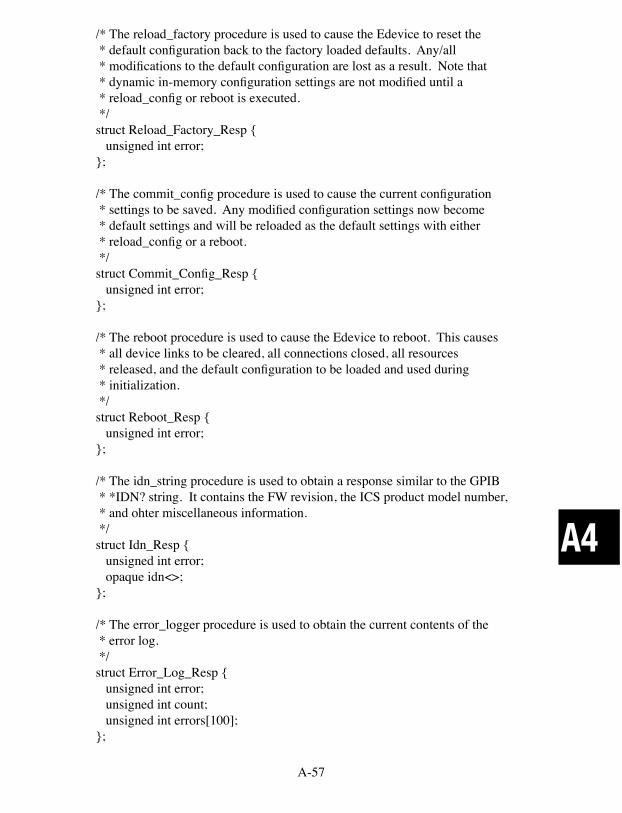
A-57
A4
/* The reload_factory procedure is used to cause the Edevice to reset the * default configuration back to the factory loaded defaults. Any/all * modifications to the default configuration are lost as a result. Note that * dynamic in-memory configuration settings are not modified until a * reload_config or reboot is executed. */struct Reload_Factory_Resp { unsigned int error;};
/* The commit_config procedure is used to cause the current configuration * settings to be saved. Any modified configuration settings now become * default settings and will be reloaded as the default settings with either * reload_config or a reboot. */struct Commit_Config_Resp { unsigned int error;};
/* The reboot procedure is used to cause the Edevice to reboot. This causes * all device links to be cleared, all connections closed, all resources * released, and the default configuration to be loaded and used during * initialization. */struct Reboot_Resp { unsigned int error;};
/* The idn_string procedure is used to obtain a response similar to the GPIB * *IDN? string. It contains the FW revision, the ICS product model number, * and ohter miscellaneous information. */struct Idn_Resp { unsigned int error; opaque idn<>;};
/* The error_logger procedure is used to obtain the current contents of the * error log. */struct Error_Log_Resp { unsigned int error; unsigned int count; unsigned int errors[100];};

A-58
A4
program ICSCONFIG { version ICSCONFIG_VERSION { Int_Name_Resp interface_name (Int_Name_Parms) = 1; Rpc_Port_Resp rpc_port_number (Rpc_Port_Parms) = 2; Core_Port_Resp core_port_number (Core_Port_Parms) = 3; Abort_Port_Resp abort_port_number (Abort_Port_Parms) = 4; Config_Port_Resp config_port_number (Config_Port_Parms) = 5; Comm_Timeout_Resp comm_timeout (Comm_Timeout_Parms) = 6; Hostname_Resp hostname (Hostname_Parms) = 7; Static_IP_Resp static_ip_mode (Static_IP_Parms) = 8; IP_Number_Resp ip_number (IP_Number_Parms) = 9; Netmask_Resp netmask (Netmask_Parms) = 10; Gateway_Resp gateway (Gateway_Parms) = 11; Keepalive_Resp keepalive (Keepalive_Parms) = 12; Gpib_Addr_Resp gpib_address (Gpib_Addr_Parms) = 13; Sys_Control_Resp system_controller (Sys_Control_Parms) = 14; Ren_Resp ren_mode (Ren_Parms) = 15; Eos_8bit_Resp eos_8_bit_mode (Eos_8bit_Parms) = 16; Auto_Eos_Resp auto_eos_mode (Auto_Eos_Parms) = 17; Eos_Active_Resp eos_active (Eos_Active_Parms) = 18; Eos_Char_Resp eos_char (Eos_Char_Parms) = 19; Reload_Config_Resp reload_config (void) = 20; Reload_Factory_Resp reload_factory (void) = 21; Commit_Config_Resp commit_config (void) = 22; Reboot_Resp reboot (void) = 23; Idn_Resp idn_string (void) = 25; Error_Log_Resp error_logger (void) = 26; } = 1;} = 1515151515;
/* * vi:tabstop=4 shiftwidth=4 expandtab */
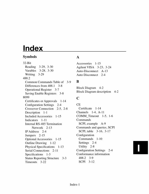
Index-1
I
IndexSymbols32-Bit
Reading 3-29, 3-30Varables 3-28, 3-30Writing 3-29
488.2Common Commands Table of 3-9Differences from 488.1 3-8Operational Register 3-7Saving Enable Registers 3-8
8099Certificates or Approvals 1-14Configuration Settings 2-4Crossover Connection 2-5, 2-8Description 1-1Included Accessories 1-15Indicators 1-11Internal RS-485 Termination Network 2-13IP Address 2-4Jumpers 2-15Optional Accessories 1-15Outline Drawing 1-12Physical Specifications 1-13Serial Connections 2-11Specifications 1-3Status Reporting Structure 3-3Timeouts 3-22
AAccessories 1-15Agilent VISA 3-23, 3-24Auto-Disconnect A-13Auto Disconnect 2-4
BBlock Diagram 4-2Block Diagram description 4-2
CCE
Certificate 1-14Channels 1-4, A-11COMM_Timeout 1-5, 1-6Commands
SCPI, example A-9Commands and queries, SCPI
SCPI, table 3-16, 3-17Configuration
Commands 1-10Settings 2-4Utility 2-8
Configuration Settings 2-4Conformance information
488.2 3-9SCPI 3-12
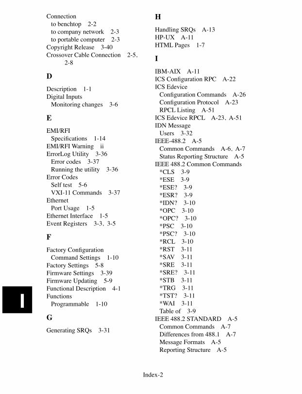
Index-2
I
Connectionto benchtop 2-2to company network 2-3to portable computer 2-3
Copyright Release 3-40Crossover Cable Connection 2-5, 2-8
DDescription 1-1Digital Inputs
Monitoring changes 3-6
EEMI/RFI
Specifications 1-14EMI/RFI Warning iiErrorLog Utility 3-36
Error codes 3-37Running the utility 3-36
Error CodesSelf test 5-6VXI-11 Commands 3-37
EthernetPort Usage 1-5
Ethernet Interface 1-5Event Registers 3-3, 3-5
FFactory Configuration
Command Settings 1-10Factory Settings 5-8Firmware Settings 3-39Firmware Updating 5-9Functional Description 4-1Functions
Programmable 1-10
GGenerating SRQs 3-31
HHandling SRQs A-13HP-UX A-11HTML Pages 1-7
IIBM-AIX A-11ICS Configuration RPC A-22ICS Edevice
Configuration Commands A-26Configuration Protocol A-23RPCL Listing A-51
ICS Edevice RPCL A-23, A-51IDN Message
Users 3-32IEEE-488.2 A-5
Common Commands A-6, A-7Status Reporting Structure A-5
IEEE 488.2 Common Commands*CLS 3-9*ESE 3-9*ESE? 3-9*ESR? 3-9*IDN? 3-10*OPC 3-10*OPC? 3-10*PSC 3-10*PSC? 3-10*RCL 3-10*RST 3-11*SAV 3-11*SRE 3-11*SRE? 3-11*STB 3-11*TRG 3-11*TST? 3-11*WAI 3-11Table of 3-9
IEEE 488.2 STANDARD A-5Common Commands A-7Differences from 488.1 A-7Message Formats A-5Reporting Structure A-5
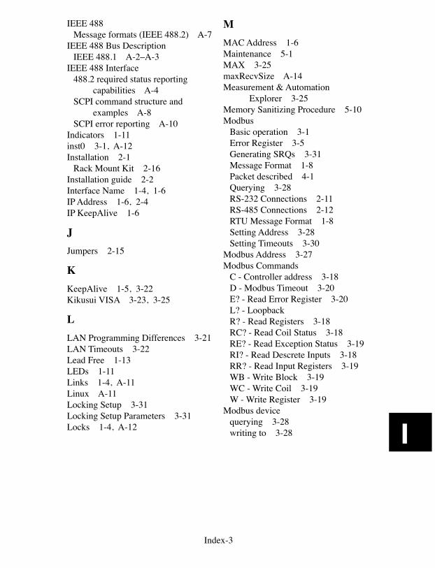
Index-3
I
IEEE 488Message formats (IEEE 488.2) A-7
IEEE 488 Bus DescriptionIEEE 488.1 A-2–A-3
IEEE 488 Interface488.2 required status reporting capabilities A-4SCPI command structure and
examples A-8SCPI error reporting A-10
Indicators 1-11inst0 3-1, A-12Installation 2-1
Rack Mount Kit 2-16Installation guide 2-2Interface Name 1-4, 1-6IP Address 1-6, 2-4IP KeepAlive 1-6
JJumpers 2-15
KKeepAlive 1-5, 3-22Kikusui VISA 3-23, 3-25
LLAN Programming Differences 3-21LAN Timeouts 3-22Lead Free 1-13LEDs 1-11Links 1-4, A-11Linux A-11Locking Setup 3-31Locking Setup Parameters 3-31Locks 1-4, A-12
MMAC Address 1-6Maintenance 5-1MAX 3-25maxRecvSize A-14Measurement & Automation Explorer 3-25Memory Sanitizing Procedure 5-10Modbus
Basic operation 3-1Error Register 3-5Generating SRQs 3-31Message Format 1-8Packet described 4-1Querying 3-28RS-232 Connections 2-11RS-485 Connections 2-12RTU Message Format 1-8Setting Address 3-28Setting Timeouts 3-30
Modbus Address 3-27Modbus Commands
C - Controller address 3-18D - Modbus Timeout 3-20E? - Read Error Register 3-20L? - Loopback R? - Read Registers 3-18RC? - Read Coil Status 3-18RE? - Read Exception Status 3-19RI? - Read Descrete Inputs 3-18RR? - Read Input Registers 3-19WB - Write Block 3-19WC - Write Coil 3-19W - Write Register 3-19
Modbus devicequerying 3-28writing to 3-28
Index-4
I
NNational Instruments VISA 3-23, 3-25Network Settings 2-5
Configuration Methods 2-5Factory Settings 1-6
OOEM
Copyright wavier 3-40Documentation 3-39
Operation 3-2SCPI conformance information 3-12Theory of 4-1
OS X A-11Outline Dimensions 1-12Output Queue 3-7
PPhysical Specifications 1-13Port usage 1-5Programmable functions 1-10Programming
32-bit variables 3-28, 3-30Configuration Methods 3-27Generating SRQs 3-31IDN Message 3-32Locking Setup 3-31Modbus Device Address 3-28Modbus timeouts 3-30Querying a Modbus Device 3-28Saving Setup 3-32Saving the setup 3-32SRQs A-13
QQuestionable Event Register 3-6Quick Installation Guide 2-2
RRack Mount Kit
Instructions 2-16RAM 4-4Repair Procedure 5-12Resetting Digital IO Configura-
tion 5-8Resetting Network Default Set-
tings 5-8Reverse Interrupt Channel A-13Reverting to Factory Settings 5-8RMA number 5-12RoHS 1-13RPC A-11
VXI-11 RPCL messages 3-33RPCL
ICS Edevices A-22VXI-11 Protocol A-17
RPCL Listing A-18RPC Programming A-17RPC Protocol 1-4, A-17, A-22RS-232
Specifications 1-8RS-485/RS-422
Specifications 1-9
SSanitizing Procedure 5-10Sanitizing the 8065's Memory 5-10Saving Setup 3-32SCPI
Channel listExamples A-10
CommandsExample A-9
Commands and queries 3-16, 3-17Command Reference Table 3-15Command structure and exam-
ple A-8Command Tree 3-13Compound commands examples A-9, A-10
Index-5
I
Conformance information 3-12Error reporting A-10STATus 3-15
SCPI Commands A-8Self Test
Errors 5-1Self Test Error Codes 5-6Serial Interface 1-8Serial Settings 2-5Serial Interface
4899/4809 2-11Baud rates 1-8Data character formats 1-8
Service Requests A-13Shipment verification 2-1SICL 3-24Sockets 1-4, A-11, A-12Specifications 1-3
RS-232 1-8RS-485/RS-422 1-9
SRQs A-13Generating from Modbus Errors 3-31
Status Byte Register 3-7Status Reporting Structure 3-3SunOS A-11
TTCP/IP Control of html variables 3-26Theory of Operation 4-1Timeout 3-30Trademarks iiTransferring Data A-14Troubleshooting 5-1
Guide 5-3, 5-4, 5-5Operating Failures 5-1Self test errors 5-1
Troubleshooting Guide 5-3
UUL/CSA/VDE
Specifications 1-14Updating Firmware 5-9
VVISA
Agilent 3-23, 3-24National Instruments 3-25
VISA Example Program A-14VXI-11
Conformance 1-4Error chart 3-35, 5-7Error Log Error Codes 3-37Error Log Utility 3-36Example VISA Program A-14IEEE-488.1 A-2Interface Name 1-4Introduction A-2Keyboard Program 3-33Operation 3-1Protocol A-11RPCL Listing A-18RPC Protocol A-17Service Requests A-13Sockets, Channels and Links A-11Supported Functions 1-4Transferring Data A-14
VXI-11 Configuration Utility 2-8VXI-11 Conformance 1-4VXI-11 Keyboard Program 3-33
WWarranty iiWebServer
Pages 3-39Specifications 1-7
Web Browser configuration method 2-5

Index-6
I
This page intentionally left blank