Embed Size (px)
Citation preview
MNS Select
Flexible cabinet for apparatus and electronics
Katalog MNS Select Eng.indd 1 08-09-25 13.35.25

ABB 2
Contents
Introduction .......................................................................................................................................................................................................................... 3
ProSelect .................................................................................................................................................................................................................................. 5
Design .......................................................................................................................................................................................................................................... 6
Cabinet selection ....................................................................................................................................................................................................... 8
Accessories
Front ....................................................................................................................................................................................................................................... 10
Rear ......................................................................................................................................................................................................................................... 12
Hinged frame ......................................................................................................................................................................................................... 13
Cover plates ............................................................................................................................................................................................................ 14
Other accessories ........................................................................................................................................................................................ 15
Equipment frame and plates ............................................................................................................................................................... 20
Dimension drawings ............................................................................................................................................................................................ 22
Aluzink® is a registered trademark.
Design, data and dimensions may be subject to change without prior notice.
Katalog MNS Select Eng.indd 2 08-09-25 13.35.25
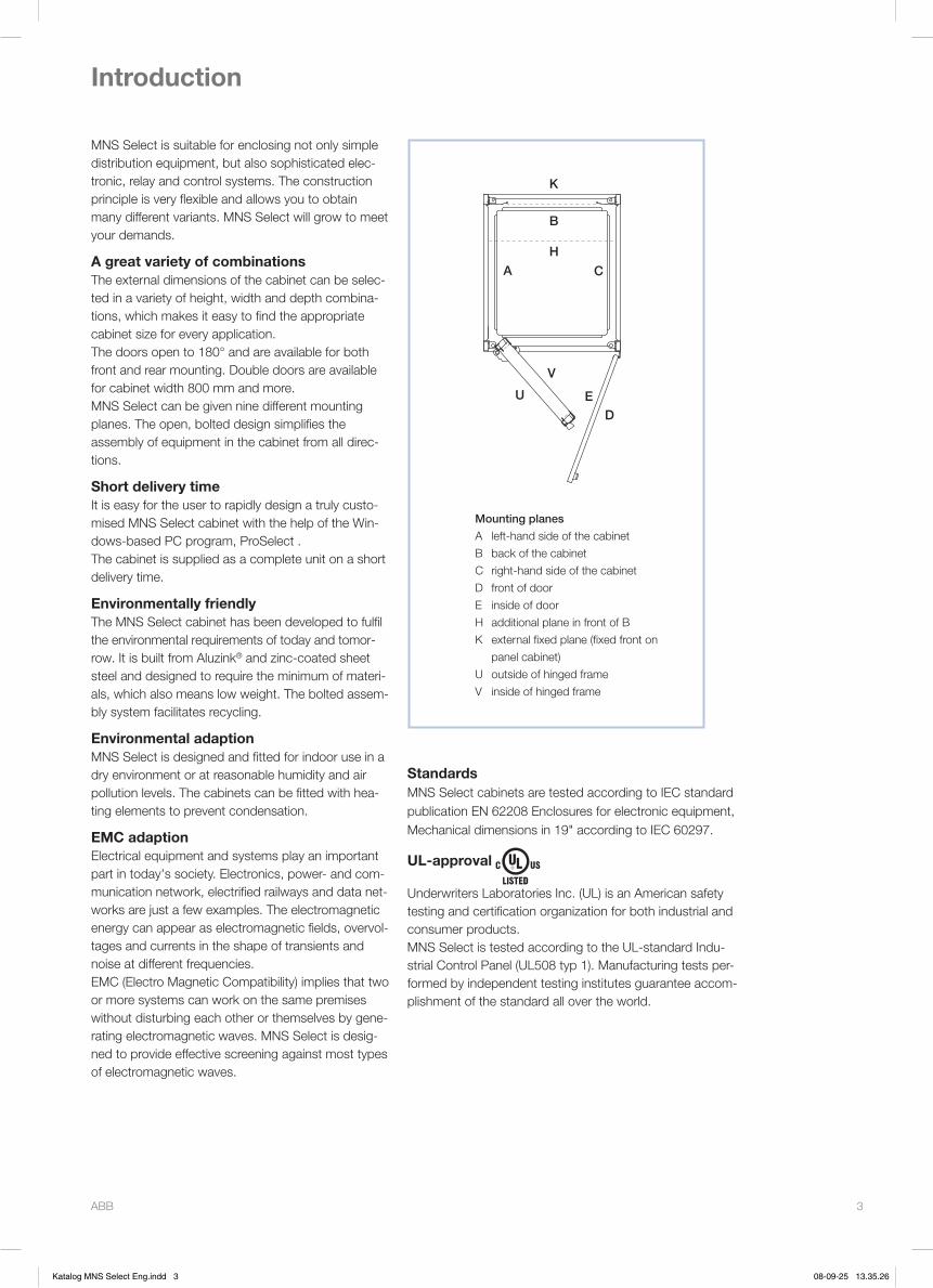
ABB 3
Aluzink® is a registered trademark.
Design, data and dimensions may be subject to change without prior notice.
Introduction
U
V
ED
A C
B
K
H
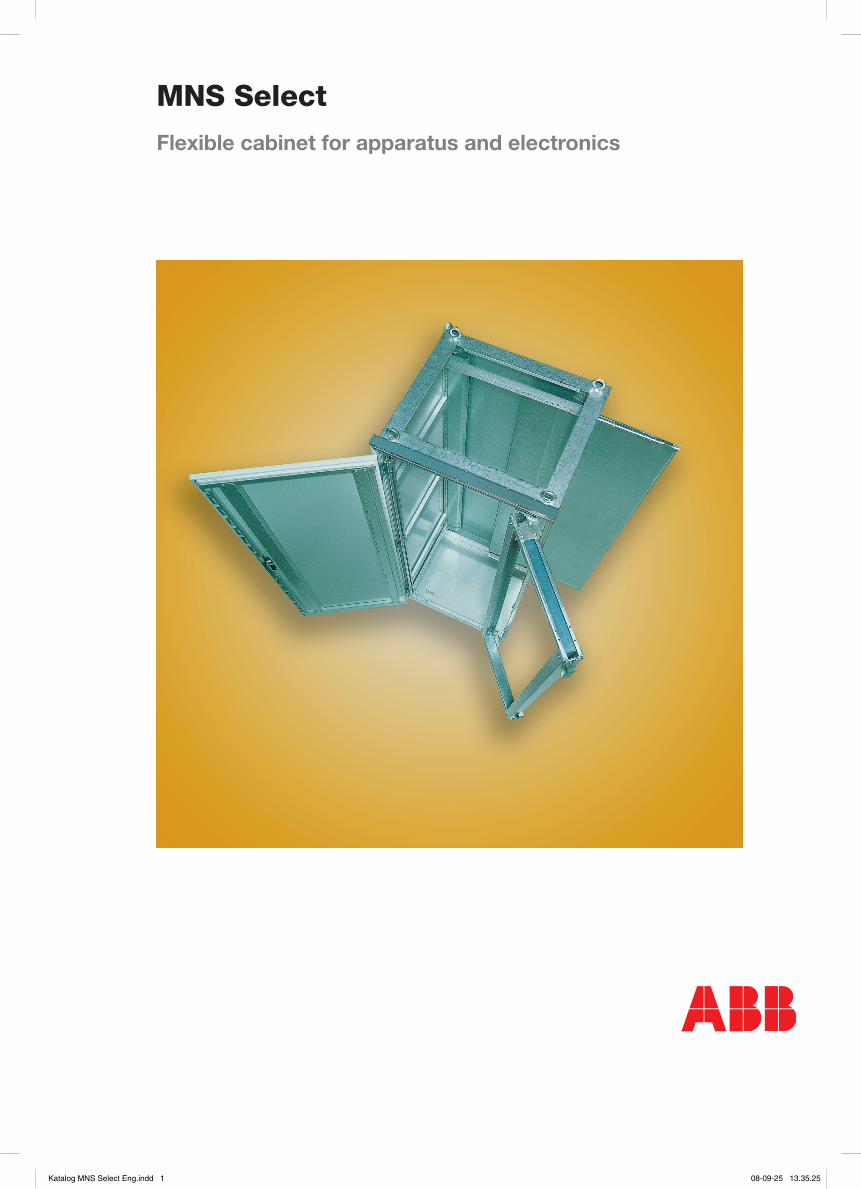
Mounting planes
A left-hand side of the cabinet
B back of the cabinet
C right-hand side of the cabinet
D front of door
E inside of door
H additional plane in front of B
K external fixed plane (fixed front on
panel cabinet)
U outside of hinged frame
V inside of hinged frame
StandardsMNS Select cabinets are tested according to IEC standard publication EN 62208 Enclosures for electronic equipment, Mechanical dimensions in 19" according to IEC 60297.
UL-approval
Underwriters Laboratories Inc. (UL) is an American safety testing and certification organization for both industrial and consumer products.MNS Select is tested according to the UL-standard Indu-strial Control Panel (UL508 typ 1). Manufacturing tests per-formed by independent testing institutes guarantee accom-plishment of the standard all over the world.
MNS Select is suitable for enclosing not only simple distribution equipment, but also sophisticated elec-tronic, relay and control systems. The construction principle is very flexible and allows you to obtain many different variants. MNS Select will grow to meet your demands.
A great variety of combinationsThe external dimensions of the cabinet can be selec-ted in a variety of height, width and depth combina-tions, which makes it easy to find the appropriate cabinet size for every application.The doors open to 180° and are available for both front and rear mounting. Double doors are avail able for cabinet width 800 mm and more.MNS Select can be given nine different mounting planes. The open, bolted design simplifies the assembly of equipment in the cabinet from all direc-tions.
Short delivery timeIt is easy for the user to rapidly design a truly custo-mised MNS Select cabinet with the help of the Win-dows-based PC program, ProSelect .The cabinet is supplied as a complete unit on a short delivery time.
Environmentally friendlyThe MNS Select cabinet has been developed to fulfil the environmental requirements of today and tomor-row. It is built from Aluzink® and zinc-coated sheet steel and designed to require the minimum of materi-als, which also means low weight. The bolted assem-bly system facilitates recycling.
Environmental adaptionMNS Select is designed and fitted for indoor use in a dry environment or at reasonable humidity and air pollution levels. The cabinets can be fitted with hea-ting elements to prevent condensation.
EMC adaptionElectrical equipment and systems play an important part in today's society. Electronics, power- and com-munication network, electrified railways and data net-works are just a few examples. The electromagnetic energy can appear as electromagnetic fields, overvol-tages and currents in the shape of transients and noise at different frequencies.EMC (Electro Magnetic Compatibility) implies that two or more systems can work on the same premises without disturbing each other or themselves by gene-rating electromagnetic waves. MNS Select is desig-ned to provide effective screening against most types of electromagnetic waves.
Katalog MNS Select Eng.indd 3 08-09-25 13.35.26
ABB 4
Introduction, cont.
02468
101214161820222426283032
300 500 700 900 1100 1300 1500 1700 1900
IP21, Bottom level
IP21, Middle level
IP21, Top level
Power losses (W)
Tem
per
atur
e ri
se (°
K)
Temperature rise, MNS Select IP21
02468
101214161820222426283032343638
200 300 400 500 600 700Power losses (W)
Tem
per
atur
e ri
se (°
K)
IP41/IP43, filter, Bottom level
IP41/IP43, filter, Middle level
IP41/IP43, filter, Top level
Temperature rise, MNS Select IP41/IP43 with filter
0
5
10
15
20
25
30
35
40
45
200 300 400 500 600Power losses (W)
Tem
per
atur
e ri
se (°
K)
IP54, Bottom level
IP54, Middle level
IP54, Top level
Temperature rise, MNS Select IP54
Degrees of protectionMNS Select cabinets are available with the following degrees of protection as per IEC 529: IP21, IP41, IP43, IP54.Definition of degrees of protection under IEC 529, IPXY:
X = 2 Protected against solid objects greater than 12 mm
X = 4 Protected against solid objects greater than 1.0 mm
X = 5 Dust-protected
Y = 1 Protected against dripping water
Y = 3 Protected against spraying water
Y = 4 Protected against splashing water
MaterialThe basic cabinet frame components are made of 1.5–2 mm corrosion-resistant sheet steel with a 20 µm Aluzink® coating. Other parts with a thickness of over 2 mm are made of zinc-coated sheet steel.
Surface treatmentOnly externally visible surfaces, i.e. doors and end panels, are powderpainted. Rear plates can be pain-ted on request.
Standard colour on painted surfacesRAL 7035 structure, light grey. The base is painted in RAL 7043, dark grey. Other colours on request.
EMCDampning measurement according to test arrange-ment EN 55011 has been performed.
VibrationsResonance test has been perfomed according to IEC 68-2-6 Test Fc:
Frequency range: 5–100 Hz
Amplitude 5–13 Hz: 1 mm
Acceleration 13–100 Hz: 0,7 g
Earthquake protectionMNS Select is tested to withstand seismic shocks according to IEEE 693 draft 5.Under standard conditions the cabinets can sustain a maximum ground acceleration (ZPA) = 0.5 g.By applying distance tubs in the bottom corner fit-tings the cabinets are capable of withstanding (ZPA) = 0.7 g.
Heat exchangerMNS Select can be equipped with an air-air heat exchanger. Other variants available on request.
Power losses, guidelinesThe temperature rises in a cabinet due to the power losses from the equipment housed in it. It also depends on the cabinet’s degree of protection (air-tightness). Self-ventilated cooling is also highly dependent on the type of equipment involved and where it is located in the cabinet.Equipment placed to ensure free air circulation around a heat source can be expected to emit more heat for the same increase in temperature than equipment which is not so well situated. Expected power losses at certain permissible temperature rises can also only be given as guidelines as shown below.There are three measured levels in the cabinet, at the top, on the bottom and in the middle. The heat sour-ces were placed evenly inside the cabinet.
Katalog MNS Select Eng.indd 4 08-09-25 13.35.27
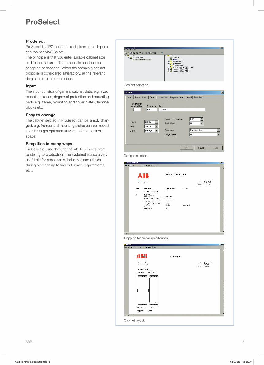
ABB 5
ProSelect
ProSelectProSelect is a PC-based project planning and quota-tion tool för MNS Select.The principle is that you enter suitable cabinet size and functional units. The proposals can then be accepted or changed. When the complete cabinet proposal is considered satisfactory, all the relevant data can be printed on paper.
InputThe input consists of general cabinet data, e.g. size, mounting planes, degree of protection and mounting parts e.g. frame, mounting and cover plates, terminal blocks etc.
Easy to changeThe cabinet selcted in ProSelect can be simply chan-ged, e.g. frames and mounting plates can be moved in order to get optimum utilization of the cabinet space.
Simplifies in many waysProSelect is used through the whole process, from tendering to production. The systemet is also a very useful aid for consultants, industries and utilities during preplanning to find out space requirements etc..
Copy on technical specification.
Cabinet selection.
Design selection.
Cabinet layout.
Katalog MNS Select Eng.indd 5 08-09-25 13.35.30

ABB 6
Design
Cabinet frameThe cabinet frame consists of four pillars, eight cor-ner fittings, a roof plate, a bottom plate and a holder for the legend plate.The pillars have mounting holes at each 25 mm.Roof and bottom plates are available with or without holes (for cable entrance). For cable entrance cover plates and EMC cover plates are available.Thanks to the open design the inside of the cabinet are easily accessible.
DoorsThe cabinets are available with different types of doors, left- and right-hand hinged, with or without glass. The opening angle is 180°.The door locks are of spagnolet design and can be opened and locked by means of a handle. As an option the doors can be provided with keylock, pad-lock or DIN-handle.Tightness and ventilation depends on the cabinets degree of protection and environmental adaption.
Rear panelThe rear panel is unpainted in standard design but can be painted as an option.IP21 has ventilation openings at the top and bottom. IP41 has ventilation openings with mesh. IP43 has ventilation openings with louver and mesh. IP54 has no ventilation openings.
Hinged frameThe cabinets can be provided with hinged frame (not applicable to 600 mm wide cabinets). The opening angle is 180°. An opening stop with lock in the end position can be fitted on requst. The opening angle is thereby limited to 135°.The frame is designed to carry 150 kg load evenly monted with center of gravity at a maximum of 150 mm from the front mounting plane (plane U). For "earthquake-proof" cabinets maximum load is 100 kg.The frame has two mounting planes with 19" dimen-sion standard: one plane for equipment mounted from outside and another plane for equipment moun-ted from inside of the frame.On request the frame can be provided with vertical cable ducts on left- and right-hand side. The frame can be moved sideways and/or in depth.
End panelsThe outer sides (left- and right-hand) in a row of cabinets and of one single cabinet shall be provided with end panels available on request.
Partition wallsPartition walls can be provided between cabinets in a row. For EMC design screen walls are used.
Rear mounting planeThe rear mounting plane consists of two vertical assembly brackets according to 19" or 24" dimensi-on standard or a mounting plate. The mounting plate can be placed centered or displaced to one side of the cabinet. On delivery the rear mounting plate is placed 25 mm in front of the rear panel but can be repositioned in depth in steps of 25 mm.The cabinets can be provided with a vertical cable duct and/or a vertical earthing bar on the rear moun-ting plane.Mounting bars are an alternative to mounting plate. These can also be repositioned in depth in steps of 25 mm.
Horizontal earthing barOn request a horizontal earthing bar can be mounted in the cabinet. Joints for connection between cabi-nets are included.The main earthing bar has the dimensions 30 x 5 mm and is available with or without connection clamps.
Frame Rear panel
End panel Hinged frame
Doors
Katalog MNS Select Eng.indd 6 08-09-25 13.35.46
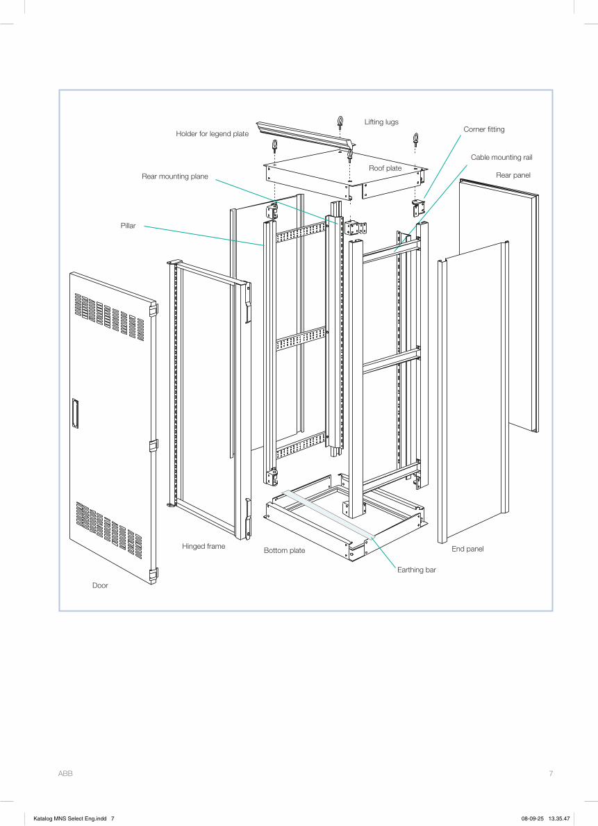
ABB 7
Holder for legend plate
Rear mounting plane
Lifting lugs
Roof plateCable mounting rail
Rear panel
Door
Hinged frame Bottom plate End panel
Corner fitting
Pillar
Earthing bar
Katalog MNS Select Eng.indd 7 08-09-25 13.35.47
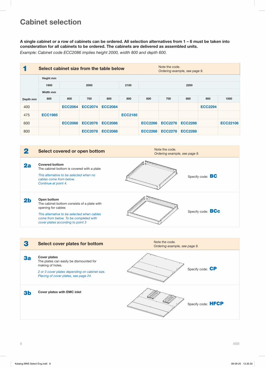
ABB 8
Cabinet selection
1 Select cabinet size from the table below Note the code.Ordering example, see page 9.
Heght mm
1900 2000 2100 2200
Depth mm
Width mm
800 600 700 800 800 600 700 800 900 1000
400 ECC2064 ECC2074 ECC2084 ECC2294
475 ECC1985 ECC2185
600 ECC2066 ECC2076 ECC2086 ECC2266 ECC2276 ECC2286 ECC22106
800 ECC2078 ECC2088 ECC2268 ECC2278 ECC2288
A single cabinet or a row of cabinets can be ordered. All selection alternatives from 1 – 6 must be taken into consideration for all cabinets to be ordered. The cabinets are delivered as assembled units.Example: Cabinet code ECC2086 implies height 2000, width 800 and depth 600.
2 Select covered or open bottom Note the code.Ordering example, see page 9.
2a Covered bottomThe cabinet bottom is covered with a plate
This alternative to be selected when no cables come from below. Continue at point 4.
Specify code: BC
2b Open bottomThe cabinet bottom consists of a plate with opening for cables
This alternative to be selected when cables come from below. To be completed with cover plates according to point 3
Specify code: BCc
3 Select cover plates for bottom Note the code.Ordering example, see page 9.
3a Cover platesThe plates can easily be dismounted for making of holes.
2 or 3 cover plates depending on cabinet size.Placing of cover plates, see page 24.
Specify code: CP
3b Cover plates with EMC inlet
Specify code: HFCP
Katalog MNS Select Eng.indd 8 08-09-25 13.35.50

ABB 9
5 Select degree of protection Note degree of protectionOrdering example, see below
Touch protectedProtected against solid objects 12 mm
Drop protectedProtected against dripping water
Touch safeProtected against solid objects 1.0 mm
Drop protectedProtected against dripping water
Touch protectedProtected against solid objects 1.0 mm
Spray protectedProtected against spraying water
Dust protectedProtected against dust penetration
Spray protectedProtected against splashing water
IP21 IP41 IP43 IP54
4 Select type of roof Note the code.Ordering example, see below
4a Completely covered roofThe roof consists of a fixed entire plate.
This alternative to be selected when no cables come from above.
Specify code: TC
4b Roof with cover plateThe plate can easily be dismounted for making of holes.
This alternative to be selected when cables come from above or if the roof is ventilated.
Specify code: TCc
6 Select whether EMC design is require or not Note the code.Ordering example, see below
EMC design implies that the cabinet is provided with conducting seals to withstand electromagnetic radiation.
EMC designnot required
EMC designrequired
6N 6Y
Ordering example Refer to 3 identical cabinets
Point Item Quantity State when ordering
1 Cabinet frame 3 ECC2078
2 Bottom 3 BCc
3 Cover plates for bottom 3 CP
4 Roof 3 TC
5 Degree of protection 3 IP41
6 EMC design 3 6Y
Supplementing cabinet details to be selected on the following pages.
Katalog MNS Select Eng.indd 9 08-09-25 13.35.51
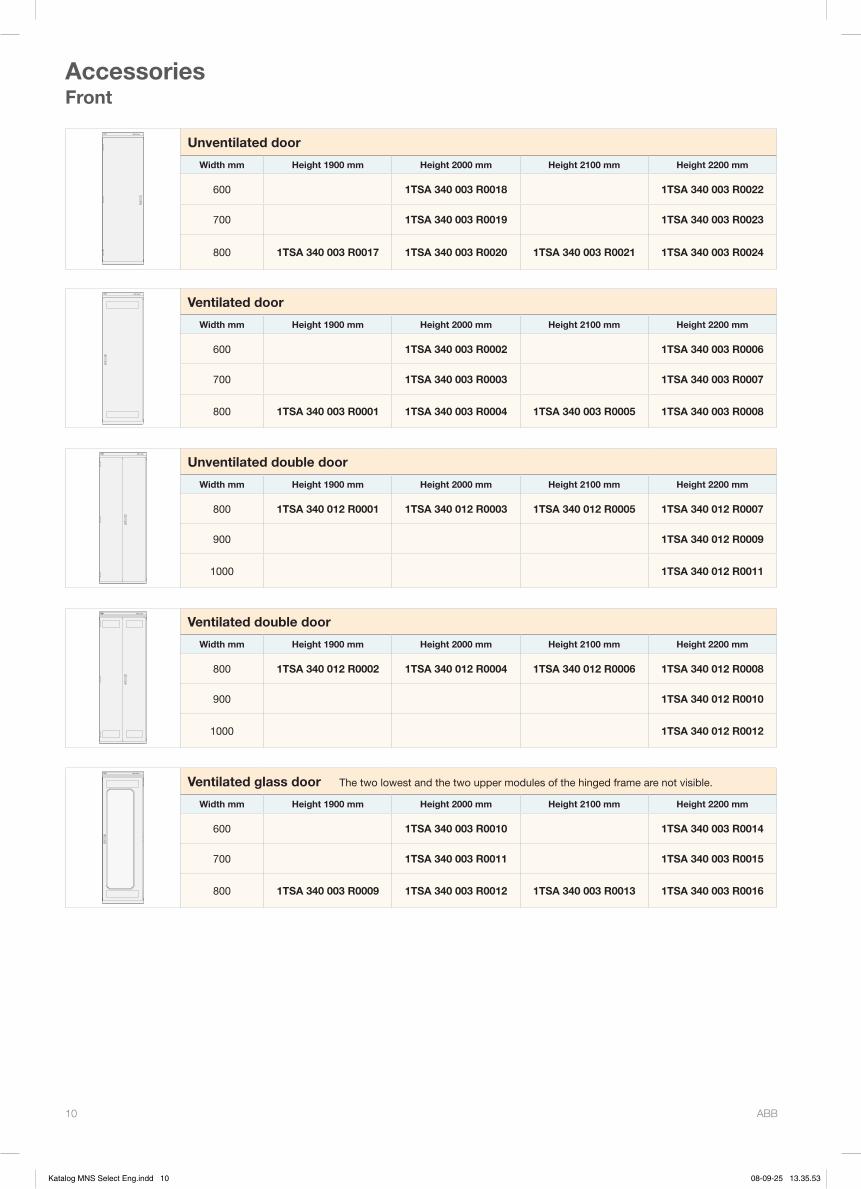
ABB 10
AccessoriesFront
MNS Select
Unventilated door
Width mm Height 1900 mm Height 2000 mm Height 2100 mm Height 2200 mm
600 1TSA 340 003 R0018 1TSA 340 003 R0022
700 1TSA 340 003 R0019 1TSA 340 003 R0023
800 1TSA 340 003 R0017 1TSA 340 003 R0020 1TSA 340 003 R0021 1TSA 340 003 R0024
MNS Select
Ventilated door
Width mm Height 1900 mm Height 2000 mm Height 2100 mm Height 2200 mm
600 1TSA 340 003 R0002 1TSA 340 003 R0006
700 1TSA 340 003 R0003 1TSA 340 003 R0007
800 1TSA 340 003 R0001 1TSA 340 003 R0004 1TSA 340 003 R0005 1TSA 340 003 R0008
MNS Select
Unventilated double door
Width mm Height 1900 mm Height 2000 mm Height 2100 mm Height 2200 mm
800 1TSA 340 012 R0001 1TSA 340 012 R0003 1TSA 340 012 R0005 1TSA 340 012 R0007
900 1TSA 340 012 R0009
1000 1TSA 340 012 R0011
MNS Select
Ventilated double door
Width mm Height 1900 mm Height 2000 mm Height 2100 mm Height 2200 mm
800 1TSA 340 012 R0002 1TSA 340 012 R0004 1TSA 340 012 R0006 1TSA 340 012 R0008
900 1TSA 340 012 R0010
1000 1TSA 340 012 R0012
MNS Select
Ventilated glass door The two lowest and the two upper modules of the hinged frame are not visible.
Width mm Height 1900 mm Height 2000 mm Height 2100 mm Height 2200 mm
600 1TSA 340 003 R0010 1TSA 340 003 R0014
700 1TSA 340 003 R0011 1TSA 340 003 R0015
800 1TSA 340 003 R0009 1TSA 340 003 R0012 1TSA 340 003 R0013 1TSA 340 003 R0016
Katalog MNS Select Eng.indd 10 08-09-25 13.35.53

ABB 11
AccessoriesFront
MNS Select
Unventilated glass door
Width mm Height 1900 mm Height 2000 mm Height 2100 mm Height 2200 mm
600 1TSA 340 003 R0026 1TSA 340 003 R0030
700 1TSA 340 003 R0027 1TSA 340 003 R0031
800 1TSA 340 003 R0025 1TSA 340 003 R0028 1TSA 340 003 R0029 1TSA 340 003 R0032
MNS Select
Ventilated, extended glass door, right hand The two lower modules of the hinged frame are not visible.
Width mm Height 1900 mm Height 2000 mm Height 2100 mm Height 2200 mm
600 1TSA 340 003 R0042 1TSA 340 003 R0046
700 1TSA 340 003 R0043 1TSA 340 003 R0047
800 1TSA 340 003 R0041 1TSA 340 003 R0044 1TSA 340 003 R0045 1TSA 340 003 R0048
MNS Select
Ventilated, extended glass door, left hand The two lower modules of the hinged frame are not visible.
Width mm Height 1900 mm Height 2000 mm Height 2100 mm Height 2200 mm
600 1TSA 340 003 R0034 1TSA 340 003 R0038
700 1TSA 340 003 R0035 1TSA 340 003 R0039
800 1TSA 340 003 R0033 1TSA 340 003 R0036 1TSA 340 003 R0037 1TSA 340 003 R0040
Panel frontThe panel front is available in two design variants. One is screwed onto the frame, the other has recessed hinges and can be opened.
Fixed panel front
Width mm Height 1900 mm Height 2000 mm Height 2100 mm Height 2200 mm
600 1TSA 340 004 R0043 1TSA 340 004 R0051
700 1TSA 340 004 R0045 1TSA 340 004 R0053
800 1TSA 340 004 R0041 1TSA 340 004 R0047 1TSA 340 004 R0049 1TSA 340 004 R0055
Panel front to be opened
Width mm Height 1900 mm Height 2000 mm Height 2100 mm Height 2200 mm
600 1TSA 340 004 R0044 1TSA 340 004 R0052
700 1TSA 340 004 R0046 1TSA 340 004 R0054
800 1TSA 340 004 R0042 1TSA 340 004 R0048 1TSA 340 004 R0050 1TSA 340 004 R0056
Katalog MNS Select Eng.indd 11 08-09-25 13.35.55
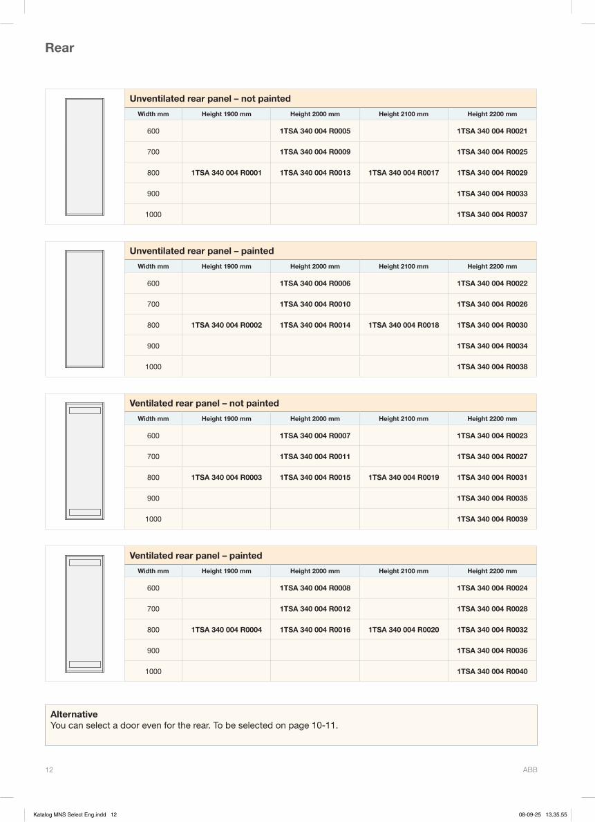
ABB 12
Unventilated rear panel – not painted
Width mm Height 1900 mm Height 2000 mm Height 2100 mm Height 2200 mm
600 1TSA 340 004 R0005 1TSA 340 004 R0021
700 1TSA 340 004 R0009 1TSA 340 004 R0025
800 1TSA 340 004 R0001 1TSA 340 004 R0013 1TSA 340 004 R0017 1TSA 340 004 R0029
900 1TSA 340 004 R0033
1000 1TSA 340 004 R0037
Unventilated rear panel – painted
Width mm Height 1900 mm Height 2000 mm Height 2100 mm Height 2200 mm
600 1TSA 340 004 R0006 1TSA 340 004 R0022
700 1TSA 340 004 R0010 1TSA 340 004 R0026
800 1TSA 340 004 R0002 1TSA 340 004 R0014 1TSA 340 004 R0018 1TSA 340 004 R0030
900 1TSA 340 004 R0034
1000 1TSA 340 004 R0038
Ventilated rear panel – not painted
Width mm Height 1900 mm Height 2000 mm Height 2100 mm Height 2200 mm
600 1TSA 340 004 R0007 1TSA 340 004 R0023
700 1TSA 340 004 R0011 1TSA 340 004 R0027
800 1TSA 340 004 R0003 1TSA 340 004 R0015 1TSA 340 004 R0019 1TSA 340 004 R0031
900 1TSA 340 004 R0035
1000 1TSA 340 004 R0039
Ventilated rear panel – painted
Width mm Height 1900 mm Height 2000 mm Height 2100 mm Height 2200 mm
600 1TSA 340 004 R0008 1TSA 340 004 R0024
700 1TSA 340 004 R0012 1TSA 340 004 R0028
800 1TSA 340 004 R0004 1TSA 340 004 R0016 1TSA 340 004 R0020 1TSA 340 004 R0032
900 1TSA 340 004 R0036
1000 1TSA 340 004 R0040
AlternativeYou can select a door even for the rear. To be selected on page 10-11.
Rear
Katalog MNS Select Eng.indd 12 08-09-25 13.35.55
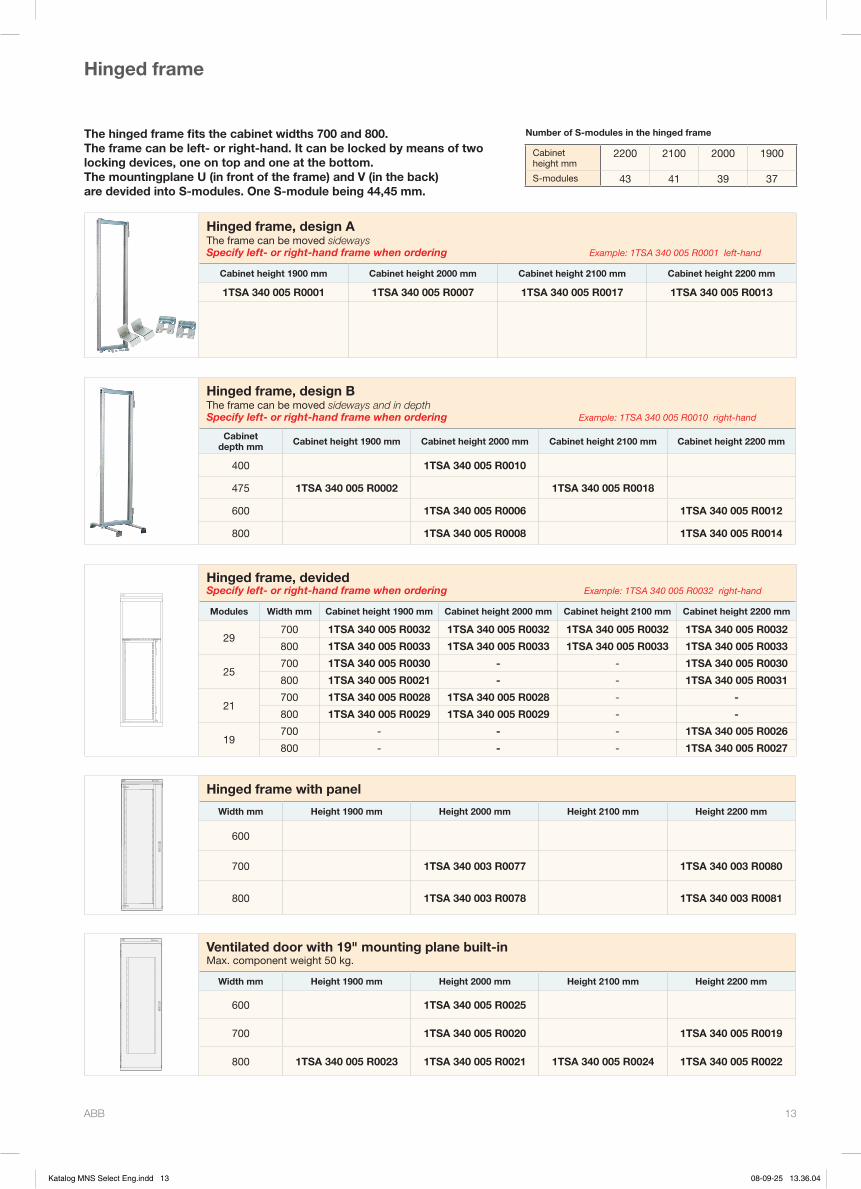
ABB 13
The hinged frame fits the cabinet widths 700 and 800. The frame can be left- or right-hand. It can be locked by means of two locking devices, one on top and one at the bottom. The mountingplane U (in front of the frame) and V (in the back) are devided into S-modules. One S-module being 44,45 mm.
Hinged frame, design AThe frame can be moved sidewaysSpecify left- or right-hand frame when ordering Example: 1TSA 340 005 R0001 left-hand
Cabinet height 1900 mm Cabinet height 2000 mm Cabinet height 2100 mm Cabinet height 2200 mm
1TSA 340 005 R0001 1TSA 340 005 R0007 1TSA 340 005 R0017 1TSA 340 005 R0013
Hinged frame, design BThe frame can be moved sideways and in depthSpecify left- or right-hand frame when ordering Example: 1TSA 340 005 R0010 right-hand
Cabinet depth mm Cabinet height 1900 mm Cabinet height 2000 mm Cabinet height 2100 mm Cabinet height 2200 mm
400 1TSA 340 005 R0010
475 1TSA 340 005 R0002 1TSA 340 005 R0018
600 1TSA 340 005 R0006 1TSA 340 005 R0012
800 1TSA 340 005 R0008 1TSA 340 005 R0014
Hinged frame, devidedSpecify left- or right-hand frame when ordering Example: 1TSA 340 005 R0032 right-hand
Modules Width mm Cabinet height 1900 mm Cabinet height 2000 mm Cabinet height 2100 mm Cabinet height 2200 mm
29700 1TSA 340 005 R0032 1TSA 340 005 R0032 1TSA 340 005 R0032 1TSA 340 005 R0032
800 1TSA 340 005 R0033 1TSA 340 005 R0033 1TSA 340 005 R0033 1TSA 340 005 R0033
25700 1TSA 340 005 R0030 - - 1TSA 340 005 R0030
800 1TSA 340 005 R0021 - - 1TSA 340 005 R0031
21700 1TSA 340 005 R0028 1TSA 340 005 R0028 - -
800 1TSA 340 005 R0029 1TSA 340 005 R0029 - -
19700 - - - 1TSA 340 005 R0026
800 - - - 1TSA 340 005 R0027
Hinged frame
Number of S-modules in the hinged frame
Cabinet height mm
2200 2100 2000 1900
S-modules 43 41 39 37
MNS Select
Hinged frame with panel
Width mm Height 1900 mm Height 2000 mm Height 2100 mm Height 2200 mm
600
700 1TSA 340 003 R0077 1TSA 340 003 R0080
800 1TSA 340 003 R0078 1TSA 340 003 R0081
MNS Select
Ventilated door with 19" mounting plane built-inMax. component weight 50 kg.
Width mm Height 1900 mm Height 2000 mm Height 2100 mm Height 2200 mm
600 1TSA 340 005 R0025
700 1TSA 340 005 R0020 1TSA 340 005 R0019
800 1TSA 340 005 R0023 1TSA 340 005 R0021 1TSA 340 005 R0024 1TSA 340 005 R0022
Katalog MNS Select Eng.indd 13 08-09-25 13.36.04
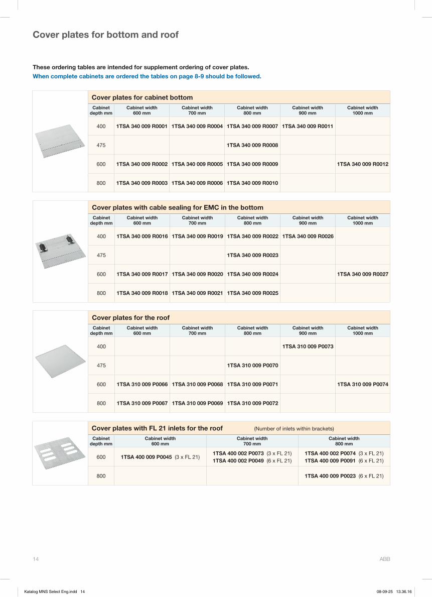
ABB 14
These ordering tables are intended for supplement ordering of cover plates.
When complete cabinets are ordered the tables on page 8-9 should be followed.
Cover plates for bottom and roof
Cover plates for cabinet bottomCabinet
depth mmCabinet width
600 mmCabinet width
700 mmCabinet width
800 mmCabinet width
900 mmCabinet width
1000 mm
400 1TSA 340 009 R0001 1TSA 340 009 R0004 1TSA 340 009 R0007 1TSA 340 009 R0011
475 1TSA 340 009 R0008
600 1TSA 340 009 R0002 1TSA 340 009 R0005 1TSA 340 009 R0009 1TSA 340 009 R0012
800 1TSA 340 009 R0003 1TSA 340 009 R0006 1TSA 340 009 R0010
Cover plates with cable sealing for EMC in the bottomCabinet
depth mmCabinet width
600 mmCabinet width
700 mmCabinet width
800 mmCabinet width
900 mmCabinet width
1000 mm
400 1TSA 340 009 R0016 1TSA 340 009 R0019 1TSA 340 009 R0022 1TSA 340 009 R0026
475 1TSA 340 009 R0023
600 1TSA 340 009 R0017 1TSA 340 009 R0020 1TSA 340 009 R0024 1TSA 340 009 R0027
800 1TSA 340 009 R0018 1TSA 340 009 R0021 1TSA 340 009 R0025
Cover plates for the roofCabinet
depth mmCabinet width
600 mmCabinet width
700 mmCabinet width
800 mmCabinet width
900 mmCabinet width
1000 mm
400 1TSA 310 009 P0073
475 1TSA 310 009 P0070
600 1TSA 310 009 P0066 1TSA 310 009 P0068 1TSA 310 009 P0071 1TSA 310 009 P0074
800 1TSA 310 009 P0067 1TSA 310 009 P0069 1TSA 310 009 P0072
Cover plates with FL 21 inlets for the roof (Number of inlets within brackets)
Cabinetdepth mm
Cabinet width 600 mm
Cabinet width 700 mm
Cabinet width 800 mm
600 1TSA 400 009 P0045 (3 x FL 21)1TSA 400 002 P0073 (3 x FL 21) 1TSA 400 002 P0049 (6 x FL 21)
1TSA 400 002 P0074 (3 x FL 21) 1TSA 400 009 P0091 (6 x FL 21)
800 1TSA 400 009 P0023 (6 x FL 21)
Katalog MNS Select Eng.indd 14 08-09-25 13.36.16

ABB 15
Other accessories
End panelsEnd panels are designed to be mounted on both sides of a single cabinet or on the two outermost sides in a row of cabinets. Each end panel adds 20 mm to the width of the cabinet and 28 mm in front and rear respectively.
Cabinetdepth mm
Cabinet height 1900 mm
Cabinet height 2000 mm
Cabinet height 2100 mm
Cabinet height 2200 mm
400 1TSA 340 006 R0002 1TSA 340 006 R0006
475 1TSA 340 006 R0001 1TSA 340 006 R0005
600 1TSA 340 006 R0003 1TSA 340 006 R0007
800 1TSA 340 006 R0004 1TSA 340 006 R0008
Cable mounting gridTo be mounted on left- or right-hand side of the cabinet. The grid mesh is 50 x 50 mm.
Specify left- or right-hand side when ordering Example: 1TSA 340 010 R0016 left-hand
Depth mm Height 2000 mm Height 2200 mm
400 1TSA 340 010 R0016 1TSA 340 010 R0020
600 1TSA 340 010 R0017 1TSA 340 010 R0021
800 1TSA 340 010 R0018 1TSA 340 010 R0022
Cable mounting railFor mounting of cable ducts and cables on cabinet side or rear.
For cabinet sideSpecify quantity of mounting rails when ordering Example: 1TSA 340 010 R0007 6 pcs
Depth 400 mm Depth 475 mm Depth 600 mm Depth 800 mm
1TSA 340 010 R0006 1TSA 340 010 R0007 1TSA 340 010 R0008 1TSA 340 010 R0009
For cabinet rearSpecify quantity of mounting rails when ordering Example: 1TSA 400 009 R0037 4 pcs
Width 600 mm Width 700 mm Width 800 mm Width 1000 mm
1TSA 400 009 P0092 1TSA 400 009 P0037 1TSA 400 009 P0036 1TSA 400 009 P0021
Cable ductThe cable duct is fitted in the middle of the cabinet side. 3 cable mounting rails are needed.Specify left- or right-hand side when ordering
Example: 1TSA 340 010 R0014 left-hand
Cable duct width x height
120 x 60 mm 1TSA 340 010 R0014
Door handles and locks
Door handle Lock insert for pivot handle
Pivot handle DIN 5 Padlock Lock insert. Two keys are provided.
1TSA 340 010 R0051 1TSA 340 010 R0063 1TSA 340 010 R0062 1TSA 340 010 R0044
Katalog MNS Select Eng.indd 15 08-09-25 13.36.37

ABB 16
Cable shelfThe cable shelf is intended for cables running between cabinets in a row. It is fitted uppermost inside the cabinet.
Width 600 mm Width 700 mm Width 800 mm Width 900 mm Width 1000 mm
1TSA 340 010 R0001 1TSA 340 010 R0002 1TSA 340 010 R0003 1TSA 340 010 R0009 1TSA 340 010 R0005
19" barsThe bars make it possible to mount equipment directed both forwards and backwards in the cabinet and also to run with cables on both sides of the cabinet. The bars can be positioned in depth in steps of 25 mm.
Depth mm Height 1900 mm38 S modules
Height 2000 mm40 S modules
Height 2100 mm42 S modules
Height 2200 mm44 S modules
400 1TSA 340 008 R0040 1TSA 340 008 R0047
475 1TSA 340 008 R0039 1TSA 340 008 R0043
600 1TSA 340 008 R0042 1TSA 340 008 R0044
800 1TSA 340 008 R0041 1TSA 340 008 R0045
19" brackets for mounting plane BThe brackets are normally fitted at the back of the cabinet. They are available for left-hand, right-hand and centred mounting and can be positioned in depth in steps of 25 mm if cable duct is available.
Width mm Height 1900 mm39 S modules
Height 2000 mm41 S modules
Height 2100 mm43 S modules
Height 2200 mm45 S modules
Bracket for left-hand or right-hand mounting
700 1TSA 340 008 R0016 1TSA 340 008 R0025
Bracket for centred mounting
600 1TSA 340 008 R0009 1TSA 340 008 R0023
700 1TSA 340 008 R0018 1TSA 340 008 R0027
800 1TSA 340 008 R0008 1TSA 340 008 R0019 1TSA 340 008 R0022 1TSA 340 008 R0031
19" bracket for mounting plane EThe bracket is fitted at the inside of the door. Can be used on covered or ventilated doors but not on glass doors. Max. loading 50 kg.
Width mm Height 1900 mm36 S modules
Height 2000 mm38 S modules
Height 2100 mm40 S modules
Height 2200 mm42 S modules
700 1TSA 340 008 R0062 1TSA 340 008 R0066
800 1TSA 340 008 R0060 1TSA 340 008 R0063 1TSA 340 008 R0064 1TSA 340 008 R0067
24" bracketThe brackets is normally fitted centred at the back of the cabinet. It can be positioned in depth in steps of 25 mm if cable duct is available. 19" and 24" brackets can be combined.
Width mm Height 1900 mm39 S modules
Height 2000 mm41 S modules
Height 2100 mm43 S modules
Height 2200 mm45 S modules
800 1TSA 340 008 R0053 1TSA 340 008 R0054
Earth wireL = 250 mm. Gn/Gy with two cable lugs M6. Connects the door or hinged frame with the cabinet frame. One earth wire is always provided. Two additional earth wires can be ordered.State quantity when ordering Example: 1TSA 340 008 R0007 2 pcs
Earth wire
1TSA 340 008 R0007
Other accessories, cont.
Katalog MNS Select Eng.indd 16 08-09-25 13.36.46
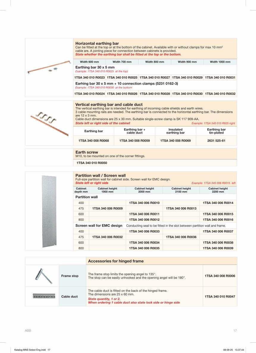
ABB 17
Partition wall / Screen wallFull-size partition wall for cabinet side. Screen wall for EMC design.State left or right side Example: 1TSA 340 006 R0015 left
Cabinetdepth mm
Cabinet height 1900 mm
Cabinet height 2000 mm
Cabinet height 2100 mm
Cabinet height 2200 mm
Partition wall
400 1TSA 340 006 R0010 1TSA 340 006 R0014
475 1TSA 340 006 R0009 1TSA 340 006 R0013
600 1TSA 340 006 R0011 1TSA 340 006 R0015
800 1TSA 340 006 R0012 1TSA 340 006 R0016
Screen wall for EMC design Conducting seal to be fitted in the slot between partition wall and frame.
400 1TSA 340 006 R0033 1TSA 340 006 R0037
475 1TSA 340 006 R0032 1TSA 340 006 R0036
600 1TSA 340 006 R0034 1TSA 340 006 R0038
800 1TSA 340 006 R0035 1TSA 340 006 R0039
Vertical earthing bar and cable ductThe vertical earthing bar is intended for earthing of incoming cable shields and earth wires. 3 cable mounting rails are needed. The earthing bar is connected to the horizontal earthing bar. The dimensions are 12 x 3 mm. Cable duct dimensions are 25 x 30 mm. Suitable single-screw clamp is SK 117 909-AA.State left or right side of the cabinet Example: 1TSA 340 010 R025 right
Earthing bar Earthing bar + cable duct
Insulated earthing bar
Earthing bar tin-plated
1TSA 340 008 R0068 1TSA 340 008 R0059 1TSA 340 008 R0069 2631 525-61
Horizontal earthing barCan be fitted at the top or at the bottom of the cabinet. Available with or without clamps for max 10 mm2 cable are. A jointing piece for connection between cabinets is provided.State whether the earthing bar shall be fitted at the top or the bottom.
Width 600 mm Width 700 mm Width 800 mm Width 900 mm Width 1000 mm
Earthing bar 30 x 5 mmExample: 1TSA 340 010 R0025 at the topl
1TSA 340 010 R0023 1TSA 340 010 R0025 1TSA 340 010 R0027 1TSA 340 010 R0029 1TSA 340 010 R0031
Earhing bar 30 x 5 mm + 10 connection clamps (5231 0162-3)Example: 1TSA 340 010 R0030 at the bottom
1TSA 340 010 R0024 1TSA 340 010 R0026 1TSA 340 010 R0028 1TSA 340 010 R0030 1TSA 340 010 R0032
Earth screwM10, to be mounted on one of the corner fittings.
1TSA 340 010 R0050
Accessories for hinged frame
Frame stop The frame stop limits the opening angel to 135 °. The stop can be easily unhooked and the opening angel will be 180 °. 1TSA 340 008 R0006
Cable duct
The cable duct is fitted on the back of the hinged frame.The dimensions are 25 x 60 mm.
State quantity, 1 or 2. When ordering 1 cable duct also state lock side or hinge side
1TSA 340 010 R0047
Katalog MNS Select Eng.indd 17 08-09-25 13.37.44
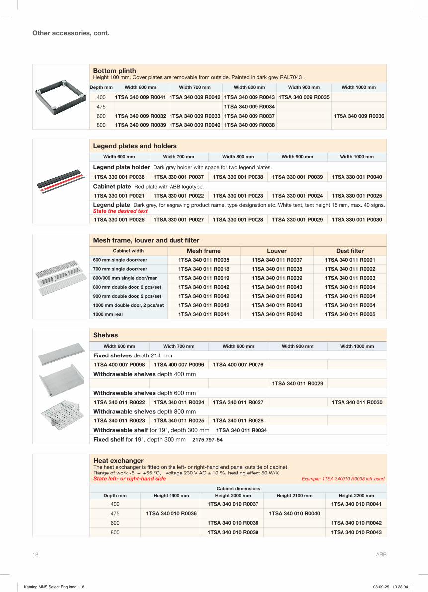
ABB 18
Bottom plinthHeight 100 mm. Cover plates are removable from outside. Painted in dark grey RAL7043 .
Depth mm Width 600 mm Width 700 mm Width 800 mm Width 900 mm Width 1000 mm
400 1TSA 340 009 R0041 1TSA 340 009 R0042 1TSA 340 009 R0043 1TSA 340 009 R0035
475 1TSA 340 009 R0034
600 1TSA 340 009 R0032 1TSA 340 009 R0033 1TSA 340 009 R0037 1TSA 340 009 R0036
800 1TSA 340 009 R0039 1TSA 340 009 R0040 1TSA 340 009 R0038
Mesh frame, louver and dust filter Cabinet width Mesh frame Louver Dust filter
600 mm single door/rear 1TSA 340 011 R0035 1TSA 340 011 R0037 1TSA 340 011 R0001
700 mm single door/rear 1TSA 340 011 R0018 1TSA 340 011 R0038 1TSA 340 011 R0002
800/900 mm single door/rear 1TSA 340 011 R0019 1TSA 340 011 R0039 1TSA 340 011 R0003
800 mm double door, 2 pcs/set 1TSA 340 011 R0042 1TSA 340 011 R0043 1TSA 340 011 R0004
900 mm double door, 2 pcs/set 1TSA 340 011 R0042 1TSA 340 011 R0043 1TSA 340 011 R0004
1000 mm double door, 2 pcs/set 1TSA 340 011 R0042 1TSA 340 011 R0043 1TSA 340 011 R0004
1000 mm rear 1TSA 340 011 R0041 1TSA 340 011 R0040 1TSA 340 011 R0005
Other accessories, cont.
Legend plates and holders
Width 600 mm Width 700 mm Width 800 mm Width 900 mm Width 1000 mm
Legend plate holder Dark grey holder with space for two legend plates.
1TSA 330 001 P0036 1TSA 330 001 P0037 1TSA 330 001 P0038 1TSA 330 001 P0039 1TSA 330 001 P0040
Cabinet plate Red plate with ABB logotype.
1TSA 330 001 P0021 1TSA 330 001 P0022 1TSA 330 001 P0023 1TSA 330 001 P0024 1TSA 330 001 P0025
Legend plate Dark grey, for engraving product name, type designation etc. White text, text height 15 mm, max. 40 signs.State the desired text
1TSA 330 001 P0026 1TSA 330 001 P0027 1TSA 330 001 P0028 1TSA 330 001 P0029 1TSA 330 001 P0030
Shelves
Width 600 mm Width 700 mm Width 800 mm Width 900 mm Width 1000 mm
Fixed shelves depth 214 mm
1TSA 400 007 P0098 1TSA 400 007 P0096 1TSA 400 007 P0076
Withdrawable shelves depth 400 mm
1TSA 340 011 R0029
Withdrawable shelves depth 600 mm
1TSA 340 011 R0022 1TSA 340 011 R0024 1TSA 340 011 R0027 1TSA 340 011 R0030
Withdrawable shelves depth 800 mm
1TSA 340 011 R0023 1TSA 340 011 R0025 1TSA 340 011 R0028
Withdrawable shelf for 19", depth 300 mm 1TSA 340 011 R0034
Fixed shelf for 19", depth 300 mm 2175 797-54
Heat exchangerThe heat exchanger is fitted on the left- or right-hand end panel outside of cabinet.Range of work -5 – +55 °C, voltage 230 V AC ± 10 %, heating effect 50 W/KState left- or right-hand side Example: 1TSA 340010 R0038 left-hand
Cabinet dimensions
Depth mm Height 1900 mm Height 2000 mm Height 2100 mm Height 2200 mm
400 1TSA 340 010 R0037 1TSA 340 010 R0041
475 1TSA 340 010 R0036 1TSA 340 010 R0040
600 1TSA 340 010 R0038 1TSA 340 010 R0042
800 1TSA 340 010 R0039 1TSA 340 010 R0043
Katalog MNS Select Eng.indd 18 08-09-25 13.38.04
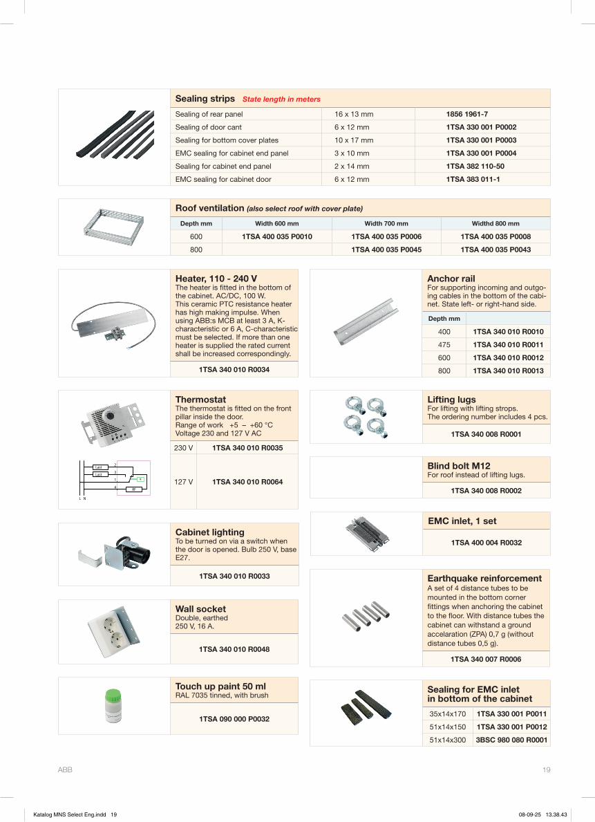
ABB 19
Heater, 110 - 240 VThe heater is fitted in the bottom of the cabinet. AC/DC, 100 W. This ceramic PTC resistance heater has high making impulse. When using ABB:s MCB at least 3 A, K-characteristic or 6 A, C-characteristic must be selected. If more than one heater is supplied the rated current shall be increased correspondingly.
1TSA 340 010 R0034
L N
Last
Last
RF
2
3
1
4
q
ThermostatThe thermostat is fitted on the front pillar inside the door.Range of work +5 – +60 °CVoltage 230 and 127 V AC
230 V 1TSA 340 010 R0035
127 V 1TSA 340 010 R0064
Anchor railFor supporting incoming and outgo-ing cables in the bottom of the cabi-net. State left- or right-hand side.
Depth mm
400 1TSA 340 010 R0010
475 1TSA 340 010 R0011
600 1TSA 340 010 R0012
800 1TSA 340 010 R0013
Touch up paint 50 mlRAL 7035 tinned, with brush
1TSA 090 000 P0032
Wall socketDouble, earthed 250 V, 16 A.
1TSA 340 010 R0048
Lifting lugsFor lifting with lifting strops. The ordering number includes 4 pcs.
1TSA 340 008 R0001
Cabinet lightingTo be turned on via a switch when the door is opened. Bulb 250 V, base E27.
1TSA 340 010 R0033
Blind bolt M12For roof instead of lifting lugs.
1TSA 340 008 R0002
EMC inlet, 1 set
1TSA 400 004 R0032
Sealing for EMC inlet in bottom of the cabinet
35x14x170 1TSA 330 001 P0011
51x14x150 1TSA 330 001 P0012
51x14x300 3BSC 980 080 R0001
Sealing strips State length in meters
Sealing of rear panel 16 x 13 mm 1856 1961-7
Sealing of door cant 6 x 12 mm 1TSA 330 001 P0002
Sealing for bottom cover plates 10 x 17 mm 1TSA 330 001 P0003
EMC sealing for cabinet end panel 3 x 10 mm 1TSA 330 001 P0004
Sealing for cabinet end panel 2 x 14 mm 1TSA 382 110-50
EMC sealing for cabinet door 6 x 12 mm 1TSA 383 011-1
Roof ventilation (also select roof with cover plate)
Depth mm Width 600 mm Width 700 mm Widthd 800 mm
600 1TSA 400 035 P0010 1TSA 400 035 P0006 1TSA 400 035 P0008
800 1TSA 400 035 P0045 1TSA 400 035 P0043
Earthquake reinforcementA set of 4 distance tubes to be mounted in the bottom corner fittings when anchoring the cabinet to the floor. With distance tubes the cabinet can withstand a ground accelaration (ZPA) 0,7 g (without distance tubes 0,5 g).
1TSA 340 007 R0006
Katalog MNS Select Eng.indd 19 08-09-25 13.38.43

ABB 20
Equiment frame and cover plates
19" equipment frameFrames are drilled for fitting terminal bases for plug-in relays of Combiflex design.The equipment frames are available in two versions: • With apparatus frame • With support frameEquipment frames with apparatus frame are desig-ned for direct mounting of terminal bases, while equipment frames with support frame are used for apparatus groups assembled on apparatus bars.The height of the frame is 4 S modules. The total width is 19" and the internal space for fitting equip-ment is 60 C = 420 mm. 1 C = 7 mm.A strip showing C modules numbered from 01 to 60 is fitted on top of the apparatus and support frames.
With ends or mounting bracketsEquipment frames are avilable with ends or mounting brackets. Equipment frames with ends are used in hinged frames, while those with mounting brackets are designed to be fitted on the rear mounting planes of cabinets (plane B).Equipment frames with ends have a cable-attach-ment rail on the left-hand side to which cables can be affixed with ties.
Front doorEquipment frames with ends are available with full-size sheet steel front door or with window of self- ex tinguishing carbonate plastic. The door is 4 S modules high.
GeneralFrames, ends and mounting brackets are galvanized. Doors are painted with RAL 7035 structure, light grey.
Equipment frame with support frame, ends and glass door.
Terminal base
Support frame
Apparatus bars
Terminal base Apparatus frame
Equipment frame with apparatus frame, ends and glass door.
19" equipment frame
Description With apparatus frame With support frame
19" equipment frame 4 S, 60 C
with mounting brackets 1TSA 340 015 R0001 1TSA 340 015 R0005
with ends but no door 1TSA 340 015 R0002 1TSA 340 015 R0006
with ends and door 1TSA 340 015 R0003 1TSA 340 015 R0007
with ends and glass door 1TSA 340 015 R0004 1TSA 340 015 R0008
Door 1TSA 340 015 R0027
Katalog MNS Select Eng.indd 20 08-09-25 13.38.43
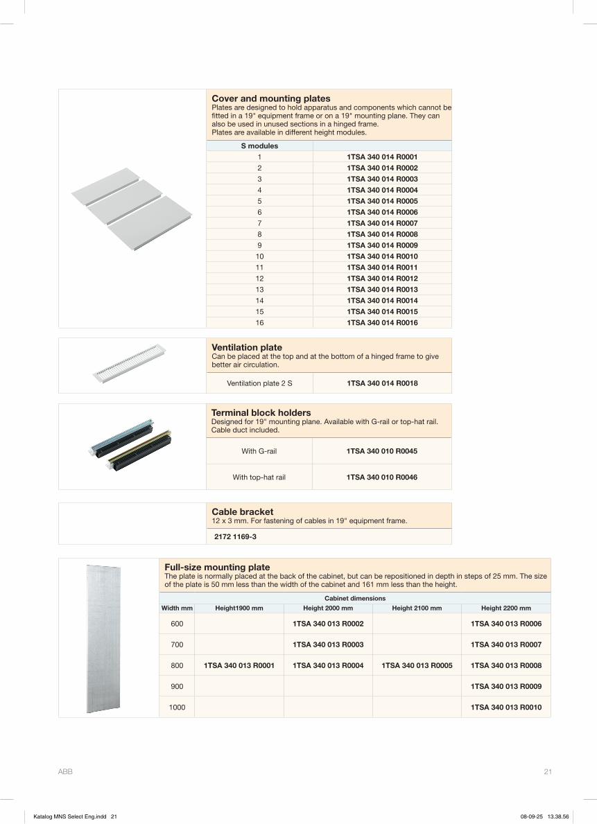
ABB 21
Cover and mounting platesPlates are designed to hold apparatus and components which cannot be fitted in a 19" equipment frame or on a 19" mounting plane. They can also be used in unused sections in a hinged frame.Plates are available in different height modules.
S modules
1 1TSA 340 014 R0001
2 1TSA 340 014 R0002
3 1TSA 340 014 R0003
4 1TSA 340 014 R0004
5 1TSA 340 014 R0005
6 1TSA 340 014 R0006
7 1TSA 340 014 R0007
8 1TSA 340 014 R0008
9 1TSA 340 014 R0009
10 1TSA 340 014 R0010
11 1TSA 340 014 R0011
12 1TSA 340 014 R0012
13 1TSA 340 014 R0013
14 1TSA 340 014 R0014
15 1TSA 340 014 R0015
16 1TSA 340 014 R0016
Terminal block holdersDesigned for 19" mounting plane. Available with G-rail or top-hat rail. Cable duct included.
With G-rail 1TSA 340 010 R0045
With top-hat rail 1TSA 340 010 R0046
Ventilation plateCan be placed at the top and at the bottom of a hinged frame to give better air circulation.
Ventilation plate 2 S 1TSA 340 014 R0018
Full-size mounting plateThe plate is normally placed at the back of the cabinet, but can be repositioned in depth in steps of 25 mm. The size of the plate is 50 mm less than the width of the cabinet and 161 mm less than the height.
Cabinet dimensions
Width mm Height1900 mm Height 2000 mm Height 2100 mm Height 2200 mm
600 1TSA 340 013 R0002 1TSA 340 013 R0006
700 1TSA 340 013 R0003 1TSA 340 013 R0007
800 1TSA 340 013 R0001 1TSA 340 013 R0004 1TSA 340 013 R0005 1TSA 340 013 R0008
900 1TSA 340 013 R0009
1000 1TSA 340 013 R0010
Cable bracket12 x 3 mm. For fastening of cables in 19" equipment frame.
2172 1169-3
Katalog MNS Select Eng.indd 21 08-09-25 13.38.56
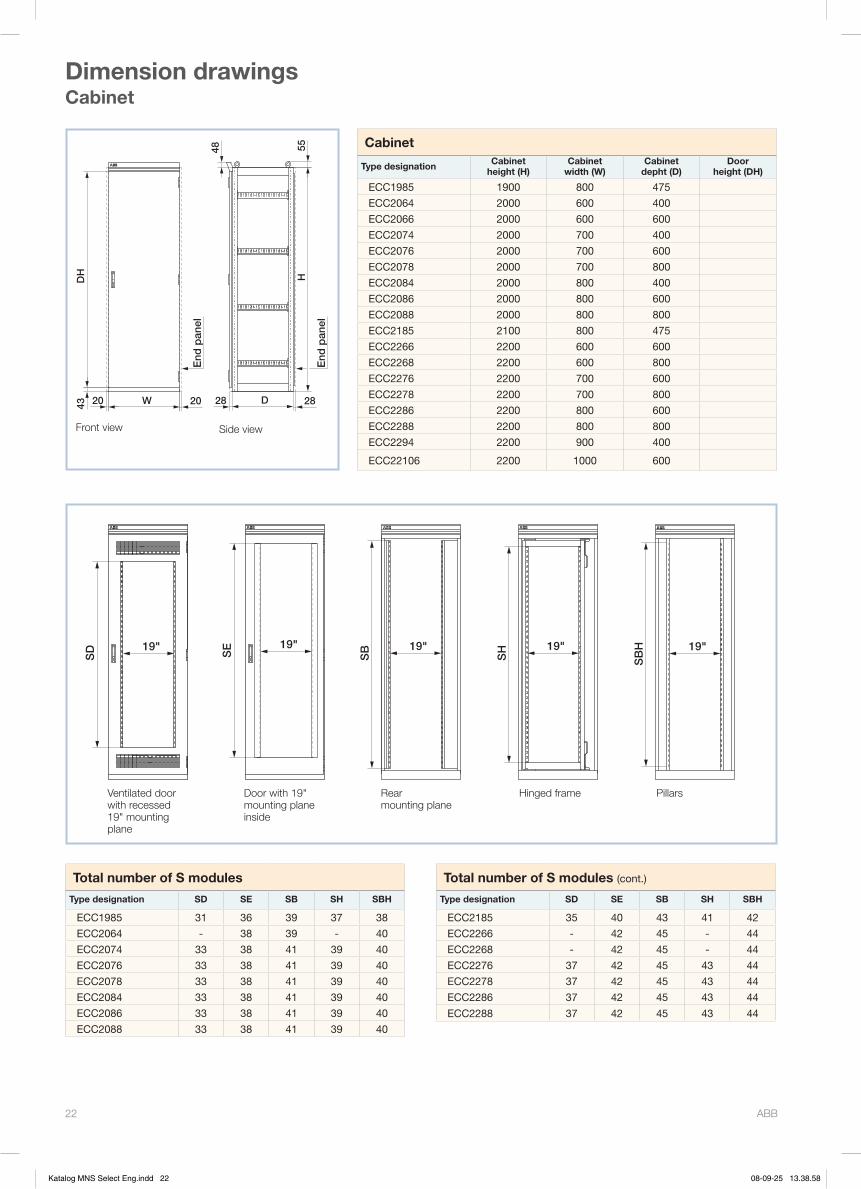
ABB 22
55
D
H
Sid
op
låt
Sid
op
låt
20
DH
43 20 28 28
48
W
Cabinet
Type designation Cabinet height (H)
Cabinet width (W)
Cabinet depht (D)
Door height (DH)
ECC1985 1900 800 475
ECC2064 2000 600 400
ECC2066 2000 600 600
ECC2074 2000 700 400
ECC2076 2000 700 600
ECC2078 2000 700 800
ECC2084 2000 800 400
ECC2086 2000 800 600
ECC2088 2000 800 800
ECC2185 2100 800 475
ECC2266 2200 600 600
ECC2268 2200 600 800
ECC2276 2200 700 600
ECC2278 2200 700 800
ECC2286 2200 800 600
ECC2288 2200 800 800
ECC2294 2200 900 400
ECC22106 2200 1000 600
Total number of S modules
Type designation SD SE SB SH SBH
ECC1985 31 36 39 37 38
ECC2064 - 38 39 - 40
ECC2074 33 38 41 39 40
ECC2076 33 38 41 39 40
ECC2078 33 38 41 39 40
ECC2084 33 38 41 39 40
ECC2086 33 38 41 39 40
ECC2088 33 38 41 39 40
Front view Side view
Ventilated door with recessed 19" mounting plane
Rear mounting plane
Hinged frame Pillars
Dimension drawingsCabinet
Total number of S modules (cont.)
Type designation SD SE SB SH SBH
ECC2185 35 40 43 41 42
ECC2266 - 42 45 - 44
ECC2268 - 42 45 - 44
ECC2276 37 42 45 43 44
ECC2278 37 42 45 43 44
ECC2286 37 42 45 43 44
ECC2288 37 42 45 43 44
Door with 19" mounting plane inside
19"
SD 19"
SE
SB 19"
SH 19" 19"
SB
H
End
pan
el
End
pan
el
Katalog MNS Select Eng.indd 22 08-09-25 13.38.58
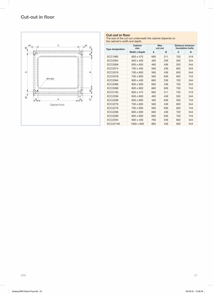
ABB 23
Ø14 (4x)
D28
28
70 A 70 2782
B10
49C49
82
Cabinet front
Cut-out in floorThe size of the cut-out underneath the cabinet depends on the cabinet's width and depth.
Type designation
Cabinet size
Max cut-out
Distance between foundation bolts
Width x Depth A B C D
ECC1985 800 x 475 660 311 702 419
ECC2064 600 x 400 460 236 502 344
ECC2066 600 x 600 460 436 502 544
ECC2074 700 x 400 560 236 602 344
ECC2076 700 x 600 560 436 602 544
ECC2078 700 x 800 560 636 602 744
ECC2084 800 x 400 660 236 702 344
ECC2086 800 x 600 660 436 702 544
ECC2088 800 x 800 660 636 702 744
ECC2185 800 x 475 660 311 702 419
ECC2266 600 x 600 460 436 502 544
ECC2268 600 x 800 460 636 502 744
ECC2276 700 x 600 560 436 602 544
ECC2278 700 x 800 560 636 602 744
ECC2286 800 x 600 660 436 702 544
ECC2288 800 x 800 660 636 702 744
ECC2294 900 x 400 760 236 802 344
ECC22106 1000 x 600 860 436 902 544
Cut-out in floor
Katalog MNS Select Eng.indd 23 08-09-25 13.38.59

ABB 24
Cabinet depth mm
Cabinet width mm See fig.
Numberof plates
Dimensions
A B C D E F G H
600
600 1 2 460 520 - - - - - -700 1 2 560 620 - - - - - -800 1 2 660 720 - - - - - -1000 1 2 860 920 - - - - - -
400
600 2 2 236 274 179 - 296 322,5 216 -700 2 2 236 274 - 267,5 296 322,5 - 316800 2 3 236 274 75 274 296 322,5 112 322,5900 2 3 236 274 175 274 296 322,5 212 322,5
475 475 2 3 311 149,5 324 149,5 371 198 361 198
800600 3 3 460 520 - - - - - -700 3 3 560 620 - - - - - -800 3 3 660 720 - - - - - -
X X
70 A
287
1850
131
B
179
335
82
25
X X
70 B
18.5
C
18.5
D
82A
H
G
F
E
X X
70 A
8228
7
18
177.
5
16.513
7
B
183.
5
212
335
Fig. 1 Fig. 2
Fig. 3
Cover plates for floor
Maximum opening for EMC inlets
140
250
35
35
128
Katalog MNS Select Eng.indd 24 08-09-25 13.39.00

ABB 25
Marking strip Apparatus frame
9
7
101.
6
177.
2
4S (1
77.8
)
37.8
465
44460 C(420)
482(=19")
2
190
168
20
25
130
Support frame
Alternative positionof apparatus frame
25 1025
190
19" equipment frame
S modules Height mm
1 44,0
2 88,5
3 133,0
4 177,4
5 221,8
6 266,3
7 310,7
8 355,2
9 399,6
10 444,0
11 488,5
12 533,0
13 577,5
14 622,0
15 666,5
16 711,0
2 *) 88,5
Marking strip Apparatus frame
Support frame
Alternative position of apparatus frame
16.5
20
SM
16.5
8.5
H
482 (=19")
465
6.5x8
Not for mountingNot for mountingNot for mounting Not for mounting
*) Ventilation plate
Equipment frame
19" cover and mounting plates
449
465
482 (19")
S
4S
S=44
.45
12.7
31.7
512
.7
6.35
8
Katalog MNS Select Eng.indd 25 08-09-25 13.39.01

ABB 26
Terminal block holder
453
482 (=19")
52.5
430
84
Top hat
MIN
2S
(89)
3525
15
68
820
Side view
Front wiev
Terminal block holder, full-size mounting plate
Mounting space
30
A
25
B30
D
36
C
F
40
E
36
200
70
Låssida
20
Cabinet height mm
Cabinet width mm
Full-size mounting plate Fixed front Openable front
A B C D E F
1900 800 1739 750 1817 799 1817 799
2000 600 1835 550 1917 599 1917 599
2000 700 1835 650 1917 699 1917 699
2000 800 1835 750 1917 799 1917 799
2100 800 1935 750 2017 799 2017 799
2200 600 2035 550 2117 599 2117 599
2200 700 2035 650 2117 699 2117 699
2200 800 2035 750 2117 799 2117 799
2200 900 2035 850 - - - -
2200 1000 2035 950 - - - -
Full-size mounting plate Fixed front Openable front
Top-hat rail
Lock side
Katalog MNS Select Eng.indd 26 08-09-25 13.39.02
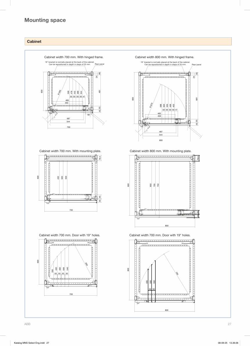
ABB 27
Cabinet
Mounting space
Cabinet width 700 mm. With mounting plate.
450
505
550
4555
76.5
600
700
650
330 40
0
460
506
540
50 50 50 50
600
700
Cabinet width 700 mm. Door with 19" holes.
650
705
750
4555
76.5
800
800
Cabinet width 800 mm. With mounting plate.
760
435
500
550
50 50
800
800
Cabinet width 700 mm. Door with 19" holes.
681
5545
544
487
800
R 6
70
465
588
450
50
564
50
535
5050
499
47
455
24
46
Ryggplåt
800
19" fästet är normalt placerat längst bak i skåpetKan flyttas i steg om 25 mm
Cabinet width 800 mm. With hinged frame.
481
5545
R 5
95
506
478
443
399
344
4750505050
465 450
487
544
700
46
Ryggplåt
24
600
93
19" fästet är normalt placerat längst bak i skåpetKan flyttas i steg om 25 mm
Cabinet width 700 mm. With hinged frame.
19" bracket is normally placed at the back of the cabinet. Can be repositioned in depth in steps of 25 mm.
19" bracket is normally placed at the back of the cabinet. Can be repositioned in depth in steps of 25 mm.Rear panel Rear panel
Katalog MNS Select Eng.indd 27 08-09-25 13.39.06

ABB AB LV SystemsSE-721 62 VÄSTERÅSTel: +46 21 34 60 00Fax: +46 21 34 61 00www.abb.se
8362
. ww
w.rc
b2.s
e1T
SC
9040
36D
0205
Katalog MNS Select Eng.indd 28 08-09-25 13.39.06