Embed Size (px)
Citation preview
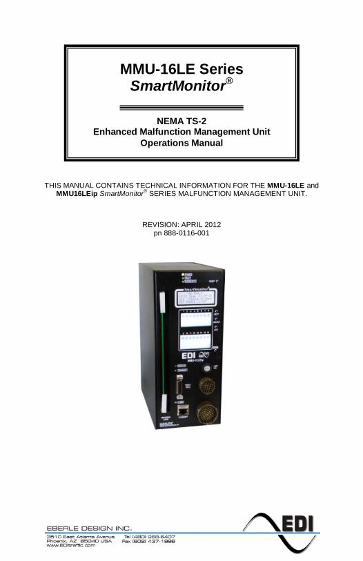
THIS MANUAL CONTAINS TECHNICAL INFORMATION FOR THE MMU-16LE and MMU16LEip SmartMonitor® SERIES MALFUNCTION MANAGEMENT UNIT.
REVISION: APRIL 2012 pn 888-0116-001
MMU-16LE Series SmartMonitor®
NEMA TS-2
Enhanced Malfunction Management Unit Operations Manual
.
THE MMU-16LE SERIES IS DESIGNED AND MANUFACTURED IN THE USA BY
EBERLE DESIGN INC. PHOENIX, ARIZONA
AN ISO 9001:2008 REGISTERED COMPANY
INFORMATION CONTAINED HEREIN IS PROPRIETARY TECHNICAL INFORMATION OF EBERLE DESIGN INC. PUBLICATION, REPRODUCTION OR USE IN WHOLE OR PART IS NOT PERMITTED EXCEPT UNDER TERMS AGREED UPON IN WRITING.
© COPYRIGHT 2004-2012 EDI
Canadian Patent No. 2,574,101 U.S. Pat. No. 7,246,037
THIS EBERLE DESIGN INC. MALFUNCTION MANAGEMENT UNIT HAS BEEN CAREFULLY INSPECTED AND TESTED TO ENSURE PROPER OPERATION. IT IS RECOMMENDED THAT THE MALFUNCTION MANAGEMENT UNIT BE TESTED AT LEAST ANNUALLY TO ENSURE PROPER OPERATION AND COMPLIANCE WITH FACTORY SPECIFICATIONS.
MAINTENANCE NOTE
.
Table of Contents
Section 1 General.................................................................................................................... 1 1.1 Description.................................................................................................................... 1 1.2 Advanced Feature Overview ....................................................................................... 1
1.2.1 Liquid Crystal Status and Field Display ............................................................. 1 1.2.2 Menu Driven Operation ...................................................................................... 1 1.2.3 Context Sensitive Help System ......................................................................... 1
1.2.3.1 Set-up Wizard ........................................................................................... 1 1.2.3.2 Diagnostic Wizard ..................................................................................... 1
1.2.4 Program Card Memory ....................................................................................... 2 1.2.5 RMS Voltage Reporting ..................................................................................... 2 1.2.6 ECcom Software Interface ................................................................................. 2 1.2.7 Nema TS-1 Operation With SDLC Mode .......................................................... 2 1.2.8 Flashing Yellow Arrow (FYA) Protected-Permissive Movement ...................... 2 1.2.9 Five Section Arrow Suppression Protected-Permissive Movement (PPLT5) .. 3
1.3 General ......................................................................................................................... 3 1.4 Field Signal Terminals ................................................................................................. 4
1.4.1 LEDguard® LED Field Signal Sensing ............................................................... 4 1.4.2 Type Select Input ............................................................................................... 4
1.4.2.1 Type 12 With SDLC Mode........................................................................ 5 1.4.2.2 Force Type 16 Mode ................................................................................ 6
Section 2 Standard Functions ............................................................................................... 7 2.1 Conflict Monitoring ....................................................................................................... 7 2.2 Red Fail Monitoring ...................................................................................................... 7
2.2.1 Red Enable Input ................................................................................................ 7 2.2.2 Walk Disable Option ........................................................................................... 7
2.3 Voltage Monitoring ....................................................................................................... 8 2.3.1 +24Vdc Supply Monitoring ................................................................................. 8
2.3.1.1 +24Vdc Monitor Inhibit Input .................................................................... 8 2.3.1.2 +24Vdc Monitor Latch Input ..................................................................... 8 2.3.1.3 +24Vdc Monitor II 12Vdc Mode................................................................ 8
2.3.2 Controller Voltage / Fault Monitor Input ............................................................. 8 2.3.2.1 CVM Monitor Latch Input.......................................................................... 9 2.3.2.2 CVM Log Disable ...................................................................................... 9
2.4 Local Flash Status Input .............................................................................................. 9 2.5 Minimum Yellow Change / Red Clearance Monitoring ............................................... 9
2.5.1 Minimum Yellow Change Interval ...................................................................... 9 2.5.1.1 Minimum Yellow Clearance Disable ........................................................ 9
2.5.2 Minimum Yellow Plus Red Interval .................................................................... 9 2.5.2.1 Minimum Yellow Plus Red Clearance Disable ...................................... 10
2.6 MMU Power Failure Detection ................................................................................... 10 2.7 Port 1 Communications.............................................................................................. 10
2.7.1 Port 1 Timeout .................................................................................................. 11 2.7.2 Port 1 Disable Input .......................................................................................... 11
2.8 Type 129 Response Frame ....................................................................................... 11 2.9 Output Relay Recovery .............................................................................................. 12 2.10 Internal Diagnostics ................................................................................................. 12
2.10.1 Memory Diagnostics ....................................................................................... 12 2.10.2 Microprocessor Monitor.................................................................................. 12 2.10.3 Internal Hardware Monitor ............................................................................. 12
Section 3 Enhanced Features ............................................................................................. 13 3.1 Hardware Features .................................................................................................... 13 3.2 Dual Indication Monitoring ......................................................................................... 13
3.2.1 Walk Disable Option ......................................................................................... 14
.
3.3 External Watchdog Monitoring .................................................................................. 14 3.4 Program Card Absent Indication ............................................................................... 14 3.5 Reset Input Detection ................................................................................................ 14 3.6 Display LED Test ....................................................................................................... 14 3.7 Recurrent Pulse Detection ......................................................................................... 15 3.8 Type Fault................................................................................................................... 15 3.9 Field Check Monitoring .............................................................................................. 16
3.9.1 Field Check Fault ............................................................................................. 16 3.9.2 Field Check Status ........................................................................................... 16
3.10 Diagnostic Wizard .................................................................................................... 17 3.11 Flashing Yellow Arrow Protected-Permissive Monitoring (FYA) ............................ 18
3.11.1 Basic FYA MODE ........................................................................................... 18 3.11.2 Compact FYAc MODE ................................................................................... 19
3.11.2.1 FYAc Type 16 Mode ............................................................................. 19 3.11.2.2 FYAc Type 12 Mode ............................................................................. 20
3.11.3 FYA Channel Assignment Diagrams ............................................................. 21 3.12 Five Section Arrow Suppression Protected-Permissive Monitoring (PPLT5) ........ 22
3.12.1 Basic PPLT5 Arrow Suppression Mode ........................................................ 22 3.12.2 PPLT5 Arrow Suppression Channel Assignment Diagrams......................... 24
Section 4 ECcom Interface .................................................................................................. 25 4.1 EDI ECcom Monitor Reports ..................................................................................... 25
4.1.1 General Data .................................................................................................... 25 4.1.2 Current Status (S) ............................................................................................ 25 4.1.3 Previous Fault (PF) Event Log ......................................................................... 25 4.1.4 AC Line (AC) Event Log ................................................................................... 25 4.1.5 Manual Reset (MR) Event Log ........................................................................ 26 4.1.6 Configuration (CF) Event Log .......................................................................... 26 4.1.7 Signal Sequence Event Log............................................................................. 26
4.2 Configuration Programming ....................................................................................... 26 4.2.1 ECcom Configuration Set-up Wizard............................................................... 26
4.3 Ethernet LAN Port ...................................................................................................... 26 Section 5 Menu Operation ................................................................................................... 27
5.1 Main Status Menu ...................................................................................................... 27 5.2 Top Level Menu ......................................................................................................... 27
5.2.1 Status ................................................................................................................ 27 5.2.2 Menu ................................................................................................................. 28
5.2.2.1 View Logs ............................................................................................... 28 5.2.2.2 View and Set Configuration .................................................................... 28 5.2.2.3 Set-up Wizard ......................................................................................... 28 5.2.2.4 Clear Logs ............................................................................................... 29 5.2.2.5 Set Clock ................................................................................................. 29
Section 6 Installation ............................................................................................................ 30 6.1 General ....................................................................................................................... 30 6.2 Program Card Programming...................................................................................... 30
6.2.1 Permissive Channel Programming .................................................................. 30 6.2.2 Minimum Flash Time Programming ................................................................. 31 6.2.3 Minimum Yellow Change Disable Programming ............................................. 31 6.2.4 Voltage Monitor Latch Programming ............................................................... 31
6.3 Enhanced Function Programming ............................................................................. 32 6.3.1 Field Check Enable Programming ................................................................... 32 6.3.2 Dual Indication Enable Programming .............................................................. 32 6.3.3 Red Fail Enable Programming ......................................................................... 32 6.3.4 Unit Option Programming................................................................................. 33
6.3.4.1 Recurrent Pulse Option .......................................................................... 33 6.3.4.2 Walk Disable Option ............................................................................... 33 6.3.4.3 Log CVM FAULTS Option ...................................................................... 33

.
6.3.4.4 External Watchdog Enable Option ......................................................... 33 6.3.4.5 +24V-II = 12 Vdc Enable Option ............................................................ 33 6.3.4.6 Program Card Memory Enable Option .................................................. 33 6.3.4.7 LEDguard® Enable Option ...................................................................... 33 6.3.4.8 Force Type 16 Mode Enable Option ...................................................... 33 6.3.4.9 Type 12 With SDLC Mode Enable Option ............................................. 33
6.3.5 View Permissives ............................................................................................. 33 6.3.6 View program card options .............................................................................. 34 6.3.7 Yellow Plus Red Clearance Disable Programming ......................................... 34 6.3.8 View Monitor ID and Name .............................................................................. 34 6.3.9 View Firmware Version .................................................................................... 34 6.3.10 Run the Setup Wizard .................................................................................... 34 6.3.11 Set Factory Default Programming ................................................................. 34 6.3.12 Set ATSI Default Programming ..................................................................... 35 6.3.13 View Configuration Check Value ................................................................... 35 6.3.14 Flashing Yellow Arrow Monitor ...................................................................... 35 6.3.15 PPLT5 Arrow Suppression Monitor ............................................................... 35
6.4 Set-up Wizard............................................................................................................. 36 6.4.1 Unused Channels ............................................................................................. 36 6.4.2 Pedestrian Channels ........................................................................................ 36 6.4.3 Protected-Permissive Turn Channels .............................................................. 37 6.4.4 Review Channel Assignments ......................................................................... 37
Section 7 Front Panel Description ...................................................................................... 38 7.1 Main Status Display ................................................................................................... 38 7.2 Channel Status Display.............................................................................................. 38 7.3 Front Panel LED Indicators........................................................................................ 38
7.3.1 Power Indicator................................................................................................. 38 7.3.2 Fault Indicator ................................................................................................... 38 7.3.3 Diagnostic Indicator .......................................................................................... 38 7.3.4 Receive Indicator .............................................................................................. 38 7.3.5 Transmit Indicator ............................................................................................. 38 7.3.6 COMM Indicator ............................................................................................... 38
7.4 Front Panel Buttons ................................................................................................... 39 7.4.1 Reset Button ..................................................................................................... 39 7.4.2 Menu Control Buttons ...................................................................................... 39
7.4.2.1 Next Button ............................................................................................. 39 7.4.2.2 Select Button........................................................................................... 39 7.4.2.3 Exit Button ............................................................................................... 39 7.4.2.4 Help Button ............................................................................................. 39
Section 8 Specifications ...................................................................................................... 40 8.1 Electrical ..................................................................................................................... 40
8.1.1 Power Requirements ........................................................................................ 40 8.1.2 AC Voltage Monitors ........................................................................................ 40 8.1.3 Power Fail Monitor ........................................................................................... 40 8.1.4 DC Voltage Monitor .......................................................................................... 40 8.1.5 Logic Inputs ...................................................................................................... 40
8.2 Mechanical ................................................................................................................. 40 8.3 Environmental ............................................................................................................ 41
Section 9 Timing Functions................................................................................................. 42 Section 10 Wiring Assignments.......................................................................................... 43
10.1 Harnessing Connectors ........................................................................................... 43 10.2 Type 16 Terminations .............................................................................................. 43
10.2.1 Type 16 Connector MS-A Pin Terminations .................................................. 43 10.2.2 Type 16 Connector MS-B Pin Terminations .................................................. 44
10.3 Type 12 Terminations .............................................................................................. 45 10.3.1 Type 12 Connector MS-A Pin Terminations .................................................. 45
.
10.3.2 Type 12 Connector MS-B Pin Terminations .................................................. 46 10.4 MMU16LE-RM & MMU16LEip-RM Rack Mount Connector ................................... 46 10.5 Programming Card Pin Connections ....................................................................... 47
10.5.1 Programming Card P1 Connector ................................................................. 47 10.5.2 Programming Card P2 Connector ................................................................. 48
10.6 Port 1 Connector ...................................................................................................... 49 10.7 EIA-232 Connector .................................................................................................. 49
10.7.1 EIA-232 Cable to a PC ................................................................................... 50 10.8 Ethernet LAN Port (J2)............................................................................................. 50
10.8.1 Ethernet LAN Cable ....................................................................................... 50
MMU-16LE SmartMonitor Operations Manual
Eberle Design Inc. Page 1
Section 1 General
1.1 DESCRIPTION
The MMU-16LE SmartMonitor® series Malfunction Management Unit (MMU) is a device used in a Traffic Controller Assembly to accomplish the detection of, and response to, improper and conflicting signals and improper operating voltages in a Controller Assembly caused by malfunctions of the Controller Unit (CU), load switches, or mis-wiring of the cabinet. The MMU-16LE SmartMonitor® also provides error sensing of two +24Vdc cabinet supplies and the controller power supplies via +24V MONITOR I, +24V MONITOR II, and Controller Voltage Monitor (CVM) inputs respectively. The Eberle Design MMU-16LE SmartMonitor® is directly interchangeable with a standard NEMA Malfunction Management Unit and meets with or exceeds all specifications outlined in Section 4 (Malfunction Management Unit) of the National Electrical Manufacturers Association (NEMA) Standards Publication TS2-2003 v02.06, Traffic Controller Assemblies With NTCIP Requirements.
1.2 ADVANCED FEATURE OVERVIEW
1.2.1 LIQUID CRYSTAL STATUS AND FIELD DISPLAY
The MMU-16LE SmartMonitor® uses a programmable alpha-numeric Liquid Crystal Display (LCD) to show monitor status and two icon based LCDs to show field signal channel and fault status. This versatile back-lighted display system provides a service technician with both detailed information regarding cabinet voltages, configuration, and status, and at the same time an easily read field signal status display showing full intersection status.
1.2.2 MENU DRIVEN OPERATION
The Display, Program, and Help modes of the MMU-16LE SmartMonitor® are controlled using a simple menu driven user interface. The menu provides an organized scheme for displaying both current status as well as reviewing historical fault status. It also provides a mechanism for setting and reviewing the monitor enhanced-feature programming without the need for a laptop computer.
1.2.3 CONTEXT SENSITIVE HELP SYSTEM
The built-in Help system provides operational guidance as well as trouble shooting advice to both the novice and expert technician. The front panel HELP button presents the requested information on the main LCD depending on the display page and context currently selected.
From start to finish, a technician can use the Set-up Wizard to accurately and quickly configure the monitor, and then use the Diagnostic Wizard to analyze the cause of a malfunction without the need for understanding complex monitor terminology and theory.
1.2.3.1 SET-UP WIZARD
The built-in Set-up Wizard (see Section 6.3.14) configures the monitor enhanced-feature programming using a simple series of intersection related questions. It allows a technician to accurately and completely program the MMU-16LE SmartMonitor® enhanced functions without the need for understanding the complexities of monitor enhanced configuration parameters.
1.2.3.2 DIAGNOSTIC WIZARD
The built-in Diagnostic Wizard (see Section 3.10) is an integral part of the Help System that provides detailed diagnostic information regarding the fault being analyzed. The Wizard provides a concise view of the signal states involved in the fault, pinpoints faulty signal
MMU-16LE SmartMonitor Operations Manual
Eberle Design Inc. Page 2
inputs, and provides guidance on how the technician should isolate the cause of the malfunction.
1.2.4 PROGRAM CARD MEMORY
All monitor enhanced-feature programming is stored in a nonvolatile memory contained on the EDI Program Card. When replacing the MMU-16LE SmartMonitor® for service or test purposes, all Nema standard and enhanced-feature programming is automatically transferred to the replacement unit when the EDI Program Card is inserted. The EDI Program Card is completely compatible with other MMU models compliant with the Nema TS2-2003 Standard.
The Program Card Memory function must be enabled before use. The factory default setting is Off. See Section 6.3.4.6.
1.2.5 RMS VOLTAGE REPORTING
Input voltages are measured using a true Root Mean Squared (RMS) technique. A dedicated Digital Signal Processor (DSP) RMS-Engine® controls the analog to digital (A/D) hardware which samples each AC input voltage a minimum of 32 times per cycle. The RMS-Engine® then calculates the true RMS voltage value producing accurate results which are very insensitive to changes in frequency, phase, wave shape, and distortion.
1.2.6 ECCOM SOFTWARE INTERFACE
The field proven EDI ECcom Signal Monitor Communications software provides a laptop computer or system interface to all information contained in the monitor. This includes detailed status, voltages, configuration, as well as historical event logs, and five thirty second Signal Sequence logs.
Event logs provide a historical record of previous fault data, ac line event data, monitor reset events, and configuration programming change events. These logs are invaluable when analyzing fault data to diagnose cabinet equipment malfunctions.
The Signal Sequence logs provide a graphical display of the signal states of all sixteen channels for up to thirty seconds prior to the fault trigger point at 50 millisecond resolution. The MMU-16LE SmartMonitor® stores these signal records for the last five fault events.
The EDI ECcom software (Version 3.5.8 or greater is required) is available at no charge from the EDI web site at www.EDItraffic.com.
1.2.7 NEMA TS-1 OPERATION WITH SDLC MODE
The MMU-16LE SmartMonitor® can operate in a Nema TS-1 configured cabinet with the full advantages of the Port 1 SDLC communications to the Controller Unit including Field Check monitoring and the Diagnostic Wizard. In this mode the MMU-16LE SmartMonitor® channel displays operate in the twelve channel configuration displaying the Walk input status directly on the associated vehicle channels. Certain programming requirements exist but typically no cabinet wiring modifications are necessary. See Section 1.4.2.1.
1.2.8 FLASHING YELLOW ARROW (FYA) PROTECTED-PERMISSIVE MOVEMENT
The MMU-16LE SmartMonitor® is designed to monitor an intersection with up to four approaches using the four section Flashing Yellow Arrow (FYA) movement outlined by the NCHRP Research Project 3-54 on Protected/Permissive signal displays with Flashing Yellow Arrows. Two cabinet configurations are supported for both the MMU Type 16 and Type 12 modes depending on the number of load switches provided and the capabilities of the Controller Unit. In both modes the MMU-16LE SmartMonitor® has been designed to provide the same broad fault coverage for the FYA approaches as it does for conventional protected left turn phases including Conflict, Red Fail, Dual Indication, and both Minimum Yellow and Minimum Yellow Plus Red Clearance monitoring. See section 3.11 for programming information.

MMU-16LE SmartMonitor Operations Manual
Eberle Design Inc. Page 3
1.2.9 FIVE SECTION ARROW SUPPRESSION PROTECTED-PERMISSIVE MOVEMENT (PPLT5)
The MMU-16LE SmartMonitor® is designed to monitor an intersection with up to four approaches using the five section PPLT5 Arrow Suppression movement. The MMU-16LE SmartMonitor® has been designed to provide the same broad fault coverage for the PPLT5 Arrow Suppression approaches as it does for conventional protected left turn phases including Conflict, Red Fail, Dual Indication, and both Minimum Yellow and Minimum Yellow Plus Red Clearance monitoring. Note that this mode is not intended for a basic Protected / Permissive “doghouse” style signal approach where the Ball section is intended for the thru vehicle phase. See section 3.12 for programming information.
1.3 GENERAL
The MMU-16LE SmartMonitor® is normally configured as a 16 channel (Type 16) monitor when operated in a TS2 type cabinet assembly. The Type 16 MMU mode is intended for those applications in which there are three circuits per channel and the MMU channels have been wired in a one-to-one correspondence with the load switches, as defined in Section 5.5.3 paragraph 9 of the NEMA Standards Publication TS2-2003 v02.06, Traffic Controller Assemblies With NTCIP Requirements. Each channel has the capability of monitoring a Green (Walk), a Yellow, and a Red (Don’t Walk) field signal output at the Terminals and Facilities field terminals.
The MMU-16LE SmartMonitor® can also be configured as a 12 channel (Type 12) monitor when operated in a NEMA TS1 type cabinet assembly. The Type 12 MMU mode is intended to provide downward compatibility with 12 channel Conflict Monitor Units (CMU) conforming to NEMA Traffic Control Systems Publication TS1-1989. Each channel has the capability of monitoring a Green, a Yellow, a Red, and a Walk field signal output at the Terminals and Facilities field terminals.
A Program Card is provided for assigning permissive channels. The MMU-16LE SmartMonitor® detects the presence of conflicting Green or Yellow ( or Walk) field signal inputs between any two or more channels not assigned to be permissive on the Program Card. The RED ENABLE input, when activated, enables the Red Fail Monitoring functions of the unit causing the monitor to trigger when it detects the absence of voltage on all three (four) of the field signal inputs of a channel. It also enables the Minimum Yellow Change/Red Clearance Monitoring function which verifies that the Yellow Change plus Red Clearance interval between the end of an active Green signal and the beginning of the next conflicting Green signal is proper. The monitoring circuitry is capable of detecting either full wave or positive and negative half-wave sinusoidal field signal inputs at the specified voltage levels.
When triggered by the detection of a fault condition which exists longer than the minimum period defined by the NEMA Standards Publication TS2-2003 v02.06 the MMU-16LE SmartMonitor® will enter the fault mode causing the OUTPUT relay to de-energize and two sets of contacts on the OUTPUT relay to transfer. The cabinet assembly should be wired such that the closure of the OUTPUT relay contacts will cause an automatic switching of the field signal outputs from normal operation to flashing operation. The MMU-16LE SmartMonitor® will then display the appropriate fault status. The loss of AC LINE will not reset the fault mode of the OUTPUT relay contacts. In the event of AC LINE loss the MMU-16LE SmartMonitor® will retain the status of all fault and channel indicators and will display the correct fault and channel status upon restoration of AC LINE.
When operating in the Type 16 mode and connected to a TS2 Controller Unit, the MMU-16LE SmartMonitor® has the ability to exchange information in a standardized format with the Controller Unit in real time using Port 1. Messages are defined in the TS2 Standard which allows the Controller Unit and the MMU-16LE SmartMonitor® to perform redundant checks on each other. The Controller Unit has access to all MMU-16LE SmartMonitor® information including field signal input status, permissive programming, and fault status. This gives the Controller Unit the capability to provide a backup monitoring function and
MMU-16LE SmartMonitor Operations Manual
Eberle Design Inc. Page 4
make enhanced event logging, remote intersection monitoring, and remote diagnostics feasible. Similarly, the MMU-16LE SmartMonitor® receives information from the Controller Unit which corresponds to the Controller Unit output commands to the load switches. This allows the MMU-16LE SmartMonitor® to better respond to and diagnose fault situations.
The TS2 Standard also provides for messages to be generated by the Controller Unit and the MMU-16LE SmartMonitor® which extend the communications capabilities of a standard assembly. The Eberle Design MMU-16LE SmartMonitor® uses these message facilities to provide enhanced application specific diagnostic reporting and monitoring.
1.4 FIELD SIGNAL TERMINALS
A GREEN, YELLOW, or WALK field signal input will be sensed as active by the MMU-16E SmartMonitor® when it exceeds the Green, Yellow, or Walk Signal Detect voltage threshold (Section 8.1.2) and a field signal input will be sensed as inactive when it is less than the Green, Yellow, or Walk Signal No-Detect voltage threshold (Section 8.1.2). Both positive and negative half wave rectified inputs will be sensed.
A RED (DON’T WALK) field signal input will be sensed as active by the MMU-16E when it exceeds the Red Signal Detect voltage threshold (Section 8.1.2) and a field signal input will be sensed as inactive when it is less than the Red Signal No-Detect voltage threshold (Section 8.1.2). Both positive and negative half wave rectified inputs will be sensed.
NOTE:
1.4.1 LEDGUARD® LED FIELD SIGNAL SENSING
When the circuit connected to the sensing input of an MMU exhibits high impedance characteristics such as caused by dimmers, burned out lamps, low wattage equipment, or no load, it may be necessary to place a low impedance device external to the unit between the MMU input and AC NEUTRAL (See Sections 5.5.3.9 and 6.2.4 of NEMA Standards Publication TS2-2003 v02.06, Traffic Controller Assemblies With NTCIP Requirements).
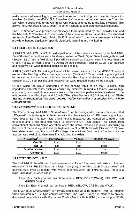
The Eberle Design MMU-16LE SmartMonitor® can be configured to use a technique called LEDguard® that is designed to better monitor the characteristics of LED based signal loads (See Section 6.3.4.7). Each field signal input is measured and compared to both a high threshold and a low threshold value to determine On / Off status. This differs from conventional standard Nema operation where the active threshold is picked according to the color of the field signal. Once the high and low On / Off thresholds (Section 8.1.2) have been determined using the input RMS voltage, the individual fault monitor functions use the appropriate threshold to determine if a fault condition exists.
LEDguard® Green/Walk Yellow Red/Don’t Walk Conflict Low Low --- Red Fail High High High
Dual Indication Low Low Low Clearance Low Low High
1.4.2 TYPE SELECT INPUT
The MMU-16LE SmartMonitor® will operate as a Type 16 monitor with sixteen channels when the TYPE SELECT input is a logic True (low). The MMU-16LE SmartMonitor® will operate as a Type 12 monitor with twelve channels when the TYPE SELECT input is a logic False (high) or open circuit.
Type 16 - Each channel has three inputs: RED (DON’T WALK), YELLOW, and GREEN (WALK).
Type 12 - Each channel has four inputs: RED, YELLOW, GREEN, and WALK.
The MMU-16LE SmartMonitor® is normally configured as a 16 channel (Type 16) monitor when operated in a TS2 type cabinet assembly. The Type 12 mode is intended to provide downward compatibility with 12 channel Conflict Monitor Units (CMU) conforming to NEMA
MMU-16LE SmartMonitor Operations Manual
Eberle Design Inc. Page 5
Traffic Control Systems Publication TS1-1989. When operating in the Type 12 mode, the MMU-16LE SmartMonitor® monitoring functions are the same as the Type 16 mode except that Port 1 communications are disabled and Field Check Monitoring is disabled. See also TYPE 12 MODE WITH SDLC Option, section 1.4.2.1.
1.4.2.1 TYPE 12 WITH SDLC MODE
The MMU-16LE SmartMonitor® can operate in a Nema TS-1 configured cabinet with the full advantages of the Port 1 SDLC communications to the Controller Unit including Field Check monitoring. In this mode the MMU-16LE SmartMonitor® channel displays operate in the Type 12 configuration displaying the Walk input status directly on the associated vehicle channels (2, 4, 6, and 8). Certain requirements exist for this mode to operate correctly:
1. This mode is limited to a maximum of four Ped phases which must be assigned to vehicle phases 2, 4, 6, and 8. The Walk field terminals must be wired to the MMU-16LE SmartMonitor® channel inputs 2W, 4W, 6W, and 8W on MMU connector pins MSA-y, MSA-FF, MSA-EE, and MSA-u respectively. This is conventional wiring for a standard Nema TS-1 cabinet. MMU input TYPE SELECT (pin #HH) must be “open circuit” (False).
2. The Controller Unit (CU) must be TS-2 Type 2 capable and provide the Port 1 EIA-485 communications port. The Controller Unit must be configured for MMU operation in the following areas (terminology and procedure may vary with different brands of CU):
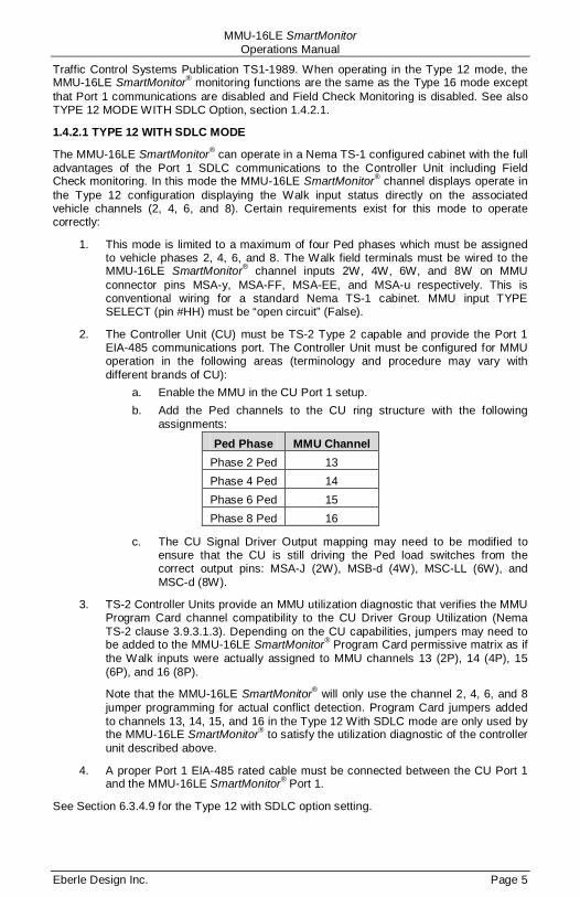
a. Enable the MMU in the CU Port 1 setup. b. Add the Ped channels to the CU ring structure with the following
assignments:
Ped Phase MMU Channel Phase 2 Ped 13 Phase 4 Ped 14 Phase 6 Ped 15 Phase 8 Ped 16
c. The CU Signal Driver Output mapping may need to be modified to ensure that the CU is still driving the Ped load switches from the correct output pins: MSA-J (2W), MSB-d (4W), MSC-LL (6W), and MSC-d (8W).
3. TS-2 Controller Units provide an MMU utilization diagnostic that verifies the MMU Program Card channel compatibility to the CU Driver Group Utilization (Nema TS-2 clause 3.9.3.1.3). Depending on the CU capabilities, jumpers may need to be added to the MMU-16LE SmartMonitor® Program Card permissive matrix as if the Walk inputs were actually assigned to MMU channels 13 (2P), 14 (4P), 15 (6P), and 16 (8P).
Note that the MMU-16LE SmartMonitor® will only use the channel 2, 4, 6, and 8 jumper programming for actual conflict detection. Program Card jumpers added to channels 13, 14, 15, and 16 in the Type 12 With SDLC mode are only used by the MMU-16LE SmartMonitor® to satisfy the utilization diagnostic of the controller unit described above.
4. A proper Port 1 EIA-485 rated cable must be connected between the CU Port 1 and the MMU-16LE SmartMonitor® Port 1.
See Section 6.3.4.9 for the Type 12 with SDLC option setting.
MMU-16LE SmartMonitor Operations Manual
Eberle Design Inc. Page 6
1.4.2.2 FORCE TYPE 16 MODE
If the cabinet is already wired for 16 channel operation but the TYPE SELECT input is not accessible due to cabinet wiring issues, the MMU-16LE SmartMonitor® can be forced to the Type 16 mode by setting the FORCE TYPE 16 option in Unit Options. See Section 6.3.4.8. The FORCE TYPE 16 mode is not compatible with the TYPE 12 WITH SDLC mode (section 1.4.2.1).
MMU-16LE SmartMonitor Operations Manual
Eberle Design Inc. Page 7
Section 2 Standard Functions
2.1 CONFLICT MONITORING
When voltages on any conflicting channels are sensed as active for more than the Conflict Fault time (Section 9), the MMU-16LE SmartMonitor® will enter the fault mode, transfer the OUTPUT relay contacts to the Fault position, and display the CONFLICT status screen. The MMU-16LE SmartMonitor® will remain in the fault mode until the unit is reset by the RESET button or the EXTERNAL RESET input. When voltages on any conflicting channels are sensed as active for less than the Conflict No-Fault time, the MMU-16LE SmartMonitor® will not transfer the OUTPUT relay contacts to the Fault position.
The MMU-16LE SmartMonitor® is fully programmable and requires the use of soldered wire jumpers on an interchangeable Programming Card to define permissive channel pairs. The Programming Card is used with both Type 16 and Type 12 operation. See Section 6.2.1 for Programming Card details.
2.2 RED FAIL MONITORING
When voltages on all inputs (G, Y, R, (W)) to a channel are sensed as inactive for more than the Red Fail Fault time (Section 9), the MMU-16LE SmartMonitor® will enter the fault mode, transfer the OUTPUT relay contacts to the Fault position, and display the RED FAIL status screen. The MMU-16LE SmartMonitor® will remain in the fault mode until the unit is reset by the RESET button or the EXTERNAL RESET input. When voltages on all inputs to a channel are sensed as inactive for less than the Red Fail No-Fault time, the MMU-16LE SmartMonitor® will not transfer the OUTPUT relay contacts to the Fault position.
Red Fail Monitoring will be disabled when the RED ENABLE input is not active. In the Type 16 mode, Red Fail Monitoring will also be disabled if the LOAD SWITCH FLASH bit is set to "1" in the Type 0 message from the Controller Unit.
Programming is provided in the SET / VIEW CONFIG menu item to enable Red Fail Monitoring on a per channel basis. See Section 6.3.3 for the programming procedure.
2.2.1 RED ENABLE INPUT
The RED ENABLE input will be sensed as active by the MMU-16LE SmartMonitor® when it exceeds the Red Enable Input threshold (Section 8.1.2). The presence of the proper operating voltage at this input enables Red Fail Monitoring, Minimum Yellow Change/Red Clearance Monitoring, and Dual Indication Monitoring. In the Type 16 mode, if the LOAD SWITCH FLASH bit is set to "1" in the Type 0 message from the Controller Unit, Red Fail Monitoring will be disabled.
The main status screen will display “RED ENABLE IS OFF” if the RED ENABLE input is not active. In the Type 16 mode, if the LOAD SWITCH FLASH bit is set to "1" in the Type 0 message from the Controller Unit, the main status screen will display “CU LS-FLASH is SET”.
2.2.2 WALK DISABLE OPTION
This option will modify the operation of Red Fail and Dual Indication Monitoring in the TS-1 Type 12 mode only. When enabled, the Red Fail and Dual Indication Monitoring function will not monitor the Walk field outputs. Absence of signals on the Green, Yellow, and Red field outputs of a channel will place the MMU-16LE SmartMonitor® into the Red Fail fault mode causing the Output relay contacts to transfer. Presence of active signals on the Walk outputs will not cause a Dual Indication when concurrent with active Red or Yellow signals. This function is enabled by the Unit Option called "WALK DISABLE" in the SET / VIEW CONFIG menu. See Section 6.3.4.2.
MMU-16LE SmartMonitor Operations Manual
Eberle Design Inc. Page 8
2.3 VOLTAGE MONITORING
2.3.1 +24VDC SUPPLY MONITORING
The +24V MONITOR I and +24V MONITOR II inputs are provided for monitoring two +24Vdc supplies in the cabinet assembly. Should loss of proper voltage occur at either of these inputs, the MMU-16LE SmartMonitor® will enter the fault mode, transfer the OUTPUT relay contacts to the Fault position, and display the appropriate 24V-1 or 24V-2 status screen. The MMU-16LE SmartMonitor® will automatically reset the OUTPUT relay when the correct input voltages are restored to both of these inputs. The MMU-16LE SmartMonitor® will remain in the fault mode for at least the time determined by the Minimum Flash programming.
A voltage greater than the +24V Monitor input threshold (Section 8.1.4) applied to both of the +24V MONITOR inputs will be sensed by the MMU-16LE SmartMonitor® as adequate for operation of the cabinet assembly. A voltage less than the +24V Monitor input threshold applied to either of the +24V MONITOR inputs will be sensed as inadequate for proper operation. When a +24V MONITOR input is sensed as inadequate for more than the +24V Monitor Fault time (Section 9), the MMU-16LE SmartMonitor® will enter the fault mode and transfer the OUTPUT relay contacts to the Fault position. When a +24V MONITOR input is sensed as inadequate for less than the +24V Monitor No-Fault time, the MMU-16LE SmartMonitor® will not transfer the OUTPUT relay contacts to the Fault position. A +24Vdc failure during the programmed Minimum Flash time or during an MMU Power Failure will not cause a fault condition.
2.3.1.1 +24VDC MONITOR INHIBIT INPUT
A +24V MONITOR INHIBIT input is provided to inhibit the operation of the +24Vdc Monitor. Application of a logic TRUE (low) state to this input will disable the operation of the +24Vdc Monitor.
2.3.1.2 +24VDC MONITOR LATCH INPUT
A jumper position is supplied on the Programming Card to allow +24Vdc failures to latch in the fault condition until the unit is reset by the activation of the RESET button or the EXTERNAL RESET input. See Section 6.2.4 for the programming procedure. A +24Vdc failure during the programmed Minimum Flash time or during an MMU Power Failure will not cause a latched fault condition.
2.3.1.3 +24VDC MONITOR II 12VDC MODE
The MMU-16LE SmartMonitor® offers the capability of setting the threshold for the +24V MONITOR II input to levels suitable for monitoring a 12 Vdc power supply. This mode is enabled by the Unit Option called "24V-2 = 12 Vdc" in the SET / VIEW CONFIG menu. See Section 6.3.4.5.
2.3.2 CONTROLLER VOLTAGE / FAULT MONITOR INPUT
This input is to be connected to the CONTROLLER UNIT VOLTAGE MONITOR (CVM) or FAULT MONITOR (FM) output from the Controller Unit. When the TRUE (low) state is absent for more than the CVM Fault time (Section 9), the MMU-16LE SmartMonitor® will enter the fault mode, transfer the OUTPUT relay contacts to the Fault position, and display the CVM status screen. When the TRUE (low) state is absent for less than the CVM No-Fault time, the MMU-16LE SmartMonitor® will not transfer the OUTPUT relay contacts to the Fault position. The MMU-16LE SmartMonitor® will automatically reset the OUTPUT relay when the True (low) state is restored to the input. The MMU-16LE SmartMonitor® will remain in the fault mode for at least the time determined by the Minimum Flash programming. A CVM failure during the programmed Minimum Flash time or during an MMU Power Failure will not cause a fault condition.
MMU-16LE SmartMonitor Operations Manual
Eberle Design Inc. Page 9
2.3.2.1 CVM MONITOR LATCH INPUT
A jumper position is supplied on the Programming Card to allow CVM failures to latch in the fault condition until the unit is reset by the activation of the RESET button or the EXTERNAL RESET input. See Section 6.2.4 for the programming procedure. A CVM failure during the programmed Minimum Flash time or during an MMU Power Failure will not cause a latched fault condition.
2.3.2.2 CVM LOG DISABLE
If CVM events are not related to a malfunction condition and occur on a regular basis such as Time of Day flash, the logging of these events can be disabled. See Section 6.3.4.3.
2.4 LOCAL FLASH STATUS INPUT
This input is to be connected to the Auto/Flash switch in the cabinet. When the TRUE (low) state is present for more than the Local Flash Fault time (Section 9), the MMU-16LE SmartMonitor® will enter the fault mode, transfer the OUTPUT relay contacts to the Fault position, and display the LOCAL FLASH status screen. When the TRUE (low) state is present for less than the Local Flash No-Fault time, the MMU-16LE SmartMonitor® will not transfer the OUTPUT relay contacts to the Fault position. The MMU-16LE SmartMonitor® will automatically reset the OUTPUT relay when the False (high) state is restored to the input. The MMU-16LE SmartMonitor® will remain in the fault mode for at least the time determined by the Minimum Flash programming. A Local Flash condition during the Minimum Flash time or during an MMU Power Failure will not cause a fault condition.
2.5 MINIMUM YELLOW CHANGE / RED CLEARANCE MONITORING
2.5.1 MINIMUM YELLOW CHANGE INTERVAL
The MMU-16LE SmartMonitor® will verify that the Yellow Change interval is at least the Clearance Fail Fault time (Section 9). The Yellow Change interval consists of the duration of time in which the Yellow field signal input is active in a sequence from Green to Yellow to Red. When this minimum interval is not satisfied the MMU-16LE SmartMonitor® will enter the fault mode, transfer the OUTPUT relay contacts to the Fault position, and display the SKIPPED Y CLEARANCE or SHORT Y CLEARANCE status screen. The MMU-16LE SmartMonitor® will remain in the fault mode until the unit is reset by the RESET button or the EXTERNAL RESET input.
Minimum Yellow Change Monitoring will be disabled when the RED ENABLE input is not active.
2.5.1.1 MINIMUM YELLOW CLEARANCE DISABLE
A set of soldered wire jumpers is provided on the Programming Card to disable Minimum Yellow Change Monitoring on a per channel basis. See Section 6.2.3 for the programming procedure.
2.5.2 MINIMUM YELLOW PLUS RED INTERVAL
The MMU-16LE SmartMonitor® will verify that the Yellow Change plus Red Clearance interval between the end of an active Green (or Walk) signal and the beginning of the next conflicting Green (or Walk) signal is at least the Clearance Fail Fault time (Section 9). This ensures a minimum clearance interval for channels without a true yellow signal such as pedestrian channels. When this minimum interval is not satisfied the MMU-16LE SmartMonitor® will enter the fault mode, transfer the OUTPUT relay contacts to the Fault position, and display the SHORT Y+R CLEARANCE status screen. The MMU-16LE SmartMonitor® will remain in the fault mode until the unit is reset by the RESET button or the EXTERNAL RESET input.
Yellow Change plus Red Clearance Monitoring will be disabled when the RED ENABLE input is not active.
MMU-16LE SmartMonitor Operations Manual
Eberle Design Inc. Page 10
2.5.2.1 MINIMUM YELLOW PLUS RED CLEARANCE DISABLE
The Red + Yellow Clearance Disable Configuration screen is provided in the SET / VIEW CONFIG menu to disable Minimum Yellow Plus Red Change Monitoring on a per channel basis. Provision to disable this function is not provided for in the NEMA Standards Publication TS2-2003 v02.06.
The MUTCD Section 4D.10 Yellow Change and Red Clearance Intervals requirement states, “A yellow signal indication shall be displayed following every CIRCULAR GREEN or GREEN ARROW signal indication”. In some legacy intersection cases this requirement is not met due to the lack of a Yellow signal head on an overlap phase (channel), and signal timing that precludes what would normally be the overlap clearance interval. In this case the Minimum Yellow Plus Red Clearance monitoring function can be disabled for that channel. It should be noted that the Minimum Yellow Plus Red Clearance monitoring function is only intended to be disabled under these special conditions.
See Section 6.3.7 for the programming procedure. The default setting for Minimum Yellow Plus Red Clearance monitoring is Enabled.
2.6 MMU POWER FAILURE DETECTION
When the AC LINE voltage is below the minimum AC Line drop-out level (Section 8.1.3) for the MMU Power Fail Respond time (Section 9), the MMU-16LE SmartMonitor® will suspend all fault monitoring functions, de-energize the OUTPUT relay, and de-energize the START relay. The POWER indicator on the front panel will flash at a rate of 2Hz to indicate the low voltage status. The main status display will indicate “AC LINE BROWNOUT” and display the current AC Line input voltage.
When the AC LINE voltage returns above the maximum AC Line restore level (Section 8.1.3) for the MMU Power Fail Restore time (Section 9), the monitor will resume normal operation and the POWER indicator on the front panel will remain illuminated. After a 2.0 +_
This expanded operating voltage range for cabinet components allows the MMU-16LE SmartMonitor® to place the intersection into flash and return to normal operation in an orderly manner when the AC LINE voltage is sufficient for proper operation. The MMU-16LE SmartMonitor® should be the first component in the cabinet to sense a low voltage condition and the last component to sense a proper AC LINE operating voltage.
0.5 second delay the START relay will be energized. After a programmable delay determined by the Minimum Flash programming, the OUTPUT relay will be energized (see Section 6.2.2).
The AC LINE and AC NEUTRAL inputs are used to generate the internal voltage supplies required to operate the monitor. AC NEUTRAL also serves as the return for all AC signals including RED ENABLE. EARTH GROUND provides an independent connection to the chassis of the unit and is isolated from AC NEUTRAL and LOGIC GROUND. LOGIC GROUND is provided for inputs which are isolated from AC NEUTRAL (i.e. +24V Monitors, CVM, CONTROLLER WATCHDOG, EXTERNAL RESET, and 24V MONITOR INHIBIT). LOGIC GROUND may be tied to AC NEUTRAL if desired.
2.7 PORT 1 COMMUNICATIONS
When operating in the Type 16 mode and connected to a TS2 Controller Unit, the MMU-16LE SmartMonitor® has the ability to exchange information in a standardized format with the Controller Unit using Port 1. For details on message formats refer to Section 3.3.1, NEMA Standards Publication TS2-2003 v02.06, Traffic Controller Assemblies With NTCIP Requirements.
The information transmitted from the Controller Unit to the MMU-16LE SmartMonitor® consists of the following message types: load switch driver commands (Type 0), time and date (Type 9). The information transmitted from the MMU-16LE SmartMonitor® to the Controller Unit consists of the following message types: field signal status and fault status

MMU-16LE SmartMonitor Operations Manual
Eberle Design Inc. Page 11
(Type 129), channel compatibility programming (Type 131). The load switch driver command (Type 0) and field signal status (Type 129) messages are exchanged approximately every 100 msec.
The electrical interface used for Port 1 conforms to the requirements of the Electronic Industries Association EIA-485 Standard. It is designed for balanced digital multipoint bus systems and provides fully differential signal operation. The baud rate used is 153.6K bit per second. The Port 1 connector intermates with a 15 pin D type connector, AMP Incorporated part number 205206-1 or equivalent. The Port 1 connector pin assignments are shown in Section 10.6.
The data and clock communications protocol used for Port 1 is a subset of the Synchronous Data Link Control (SDLC) Protocol, as defined by International Business Machines Corporation Document GA27-3093-3 (June 1986). This protocol utilizes sophisticated error checking computations to verify message integrity. In addition, the Eberle Design MMU-16LE SmartMonitor® adds enhanced communications diagnostics and error handling capabilities to ensure proper communications occur.
2.7.1 PORT 1 TIMEOUT
When a Type 0 message from the Controller Unit has not been correctly received for the Port 1 Timeout Fault time (Section 9), the MMU-16LE SmartMonitor® will enter the fault mode, transfer the OUTPUT relay contacts to the Fault position, and display the PORT 1 FAIL status screen. When receipt of a Type 0 message again occurs, the MMU-16LE SmartMonitor® will exit the fault state and transfer the OUTPUT relay contacts to the normal position, except when three Port 1 faults have occurred in a calendar day.
After the third Port 1 fault in a calendar day, the MMU-16LE SmartMonitor® will remain in the fault mode until the unit is reset by the RESET button or the EXTERNAL RESET input. Loss of AC Line after the third Port 1 fault will exit the fault state and reset the Port 1 fail count to 2.
A PORT 1 timeout failure during the programmed Minimum Flash time or during an MMU Power Failure will not cause a latched fault condition.
2.7.2 PORT 1 DISABLE INPUT
Port 1 communications will be disabled when the PORT 1 DISABLE input is at a logic True (low) state OR the TYPE SELECT input is at a logic False (high) state (Type 12 mode). Port 1 communications will be enabled when the PORT 1 DISABLE input is at a logic False (high) state AND the TYPE SELECT input is True (low) (Type 16 mode).
2.8 TYPE 129 RESPONSE FRAME
Five bits designated as Spare Bit #1 through Spare bit #5 of the Type 129 response frame to the Controller Unit are used by the MMU-16LE SmartMonitor® to indicate the type of failure detected for enhanced fault monitoring capabilities of the MMU-16LE. Refer to sections 3.9, 3.2, 3.7, 3.2.1, and 2.5.2 of this manual for further information.
Fault Type Bit # Nema Designation
Field Check Fault/Status 67 Spare Bit #1 Dual Indication Fault 68 Spare Bit #2 RP Detection Status 69 Spare Bit #3 External Watchdog Fault 70 Spare Bit #4 Yellow Plus Red Clearance 71 Spare Bit #5
MMU-16LE SmartMonitor Operations Manual
Eberle Design Inc. Page 12
2.9 OUTPUT RELAY RECOVERY
Prior to the MMU-16LE SmartMonitor® transferring the Output Relay contacts from the fault state to the no-fault state, a transition state with duration of 500 milliseconds will occur. During the transition state the Output Relay will remain in the fault state and the Start-up Flash Call bit in the Type 129 frame will be set to 1.
2.10 INTERNAL DIAGNOSTICS
The MMU-16LE SmartMonitor® is supplied with a resident series of self check diagnostic capabilities which monitor for correct operation of the MMU-16LE SmartMonitor® both at power-up and continuously during operation. Should an internal diagnostic error occur, other fault indicators that may be concurrently displayed with the DIAGNOSTIC indicator may not be valid due to the nature of these hardware and/or firmware failures.
2.10.1 MEMORY DIAGNOSTICS
On power-up, the MMU-16LE SmartMonitor® verifies the operation of all memory components including RAM, EPROM, and non-volatile EEPROM. During operation the MMU-16LE SmartMonitor® continuously performs a check sum verification of the non-volatile memory components. When either diagnostic test fails, the MMU-16LE SmartMonitor® will enter the fault mode, transfer the OUTPUT relay contacts to the Fault position, and illuminate the DIAGNOSTIC indicator. An MMU Power Failure will reset the Diagnostic fault state of the monitor (see Section 2.6). Due to the nature of these hardware/firmware failures, other fault indicators that may be concurrently displayed with the DIAGNOSTIC indicator may not be valid.
2.10.2 MICROPROCESSOR MONITOR
The MMU-16LE SmartMonitor® contains circuitry which monitors the operation of the internal microprocessor. This monitoring circuit receives a logic transition signal from the microprocessor every 5 msec. When this logic transition is not received for 300 msec, the MMU-16LE SmartMonitor® will enter the fault mode, transfer the OUTPUT relay contacts to the Fault position, and illuminate the DIAGNOSTIC indicator. Due to the nature of these hardware/firmware failures, other fault indicators that may be concurrently displayed with the DIAGNOSTIC indicator may not be valid.
This type of failure is configured as latching. If the microprocessor resumes operation the unit will not return to normal operation. With latching operation, only a loss of AC Line will restore operation. If non-latching operation is desired, internal jumper E1 (Latching MPU Fault) may be removed.
2.10.3 INTERNAL HARDWARE MONITOR
The MMU-16LE SmartMonitor® contains circuitry which verifies the operation of the many sections of the internal circuitry. Should a malfunction be detected, the MMU-16LE SmartMonitor® will enter the fault mode, transfer the OUTPUT relay contacts to the Fault position, and illuminate the DIAGNOSTIC indicator. An MMU Power Failure will reset the Diagnostic fault state of the monitor (see Section 2.6). Due to the nature of this hardware failure, other fault indicators that may be concurrently displayed with the DIAGNOSTIC indicator may not be valid.
MMU-16LE SmartMonitor Operations Manual
Eberle Design Inc. Page 13
Section 3 Enhanced Features
The following enhanced features are provided on the Eberle Design MMU-16LE SmartMonitor® for additional monitoring functions and to increase the reliability of the MMU-16LE SmartMonitor® monitor operation.
3.1 HARDWARE FEATURES
The MMU-16LE SmartMonitor® is a dual microprocessor based unit. All monitoring functions and features are firmware programmable which permits upgrades or modifications by simply reprogramming the Flash memory device containing the firmware with the upgraded version. Thus, most changes to the MMU-16LE SmartMonitor® specifications may be accommodated without modifying the hardware.
Since all critical timing functions are accomplished by the microprocessor, the quartz crystal based accuracy results in very precise and repeatable measurements. This accuracy is maintained on functions from timing fault conditions to implementing a unique firmware based digital sampling and filtering algorithm. This algorithm is applied to all AC field signals to help eliminate false detection in a "noisy" AC line environment.
Input voltages are measured using a true Root Mean Squared (RMS) technique. A dedicated microcontroller RMS-Engine® controls the analog to digital (A/D) hardware that samples each AC input voltage at least 32 times per cycle. The RMS-Engine® then calculates the true RMS voltage value, producing accurate results which are very insensitive to changes in frequency, phase, wave shape, and distortion. Voltage references are temperature compensated for constant voltage levels within the operating temperature range.
A nonvolatile EEPROM device is utilized to retain fault status information and event logs through an AC Line power interruption. The correct fault indications will be displayed upon restoration of AC Line power. This EEPROM device requires no battery back-up. The time of day in the MMU-16LE SmartMonitor® is stored in a battery-backed real time clock circuit. Should this battery fail, only current time of day and date information will be lost. No monitor configuration programming is stored under battery power.
3.2 DUAL INDICATION MONITORING
In Type 16 mode this monitoring function detects simultaneous input combinations of active Green (Walk), Yellow, or Red (Don’t Walk) field signal inputs on the same channel. In Type 12 mode this monitoring function detects simultaneous input combinations of active Green and Yellow, Green and Red, Yellow and Red, Walk and Yellow, or Walk and Red field signal inputs on the same channel. When voltages on any two inputs of a channel are sensed as active for more than the Dual Indication Fault time (Section 9), the MMU-16LE SmartMonitor® will enter the fault mode, transfer the OUTPUT relay contacts to the Fault position, and display the DUAL INDICATION status screen. When operating in the Type 16 mode with Port 1 communications enabled, Bit #68 (Spare Bit #2) of the Type #129 response frame will be set to indicate a Dual Indication fault has been detected. The MMU-16LE SmartMonitor® will remain in the fault mode until the unit is reset by the RESET button or the EXTERNAL RESET input. When voltages on any two inputs of a channel are sensed as active for less than the Dual Indication Fault time, the MMU-16LE SmartMonitor® will not transfer the OUTPUT relay contacts to the Fault position.
Dual Indication Monitoring may anticipate and prevent a possible conflicting signal display in the intersection in the event that a proceed signal on the current phase hangs up and is constantly detected as active. An open or no load condition (i.e., burned-out bulb) may be also detected as an active signal depending on the output impedance characteristics of the load switch (i.e. load switch leakage current), and may cause a Dual Indication Fault.
MMU-16LE SmartMonitor Operations Manual
Eberle Design Inc. Page 14
Programming for Dual Indication is provided in the SET / VIEW CONFIG menu item to enable Dual Indication Monitoring on a per channel basis. See Section 6.3.2 for the programming procedure.
Dual Indication Monitoring will be disabled when the RED ENABLE input is not active.
3.2.1 WALK DISABLE OPTION
This option will modify the operation of Red Fail and Dual Indication Monitoring in the TS-1 Type 12 mode only. When enabled, the Red Fail and Dual Indication Monitoring function will not monitor the Walk field outputs. Absence of signals on the Green, Yellow, and Red field outputs of a channel will place the MMU-16LE SmartMonitor® into the Red Fail fault mode causing the Output relay contacts to transfer. Presence of active signals on the Walk outputs will not cause a Dual Indication when concurrent with active Red or Yellow signals. This function is enabled by the Unit Option called "WALK DISABLE" in the SET / VIEW CONFIG menu. See Section 6.3.4.2.
3.3 EXTERNAL WATCHDOG MONITORING
This function monitors an optional external watchdog output from a Controller Unit or other external cabinet circuitry. The external source should toggle the EXTERNAL WATCHDOG input logic state once every 100 msec. If the MMU-16LE SmartMonitor® does not receive a change in state on the EXTERNAL WATCHDOG input for the External Watchdog Fault time (Section 9), the MMU-16LE SmartMonitor® will enter the fault mode, transfer the OUTPUT relay contacts to the Fault position, and display the EXT WATCHDOG status screen. When operating in the Type 16 mode with Port 1 communications enabled, Bit #70 (Spare Bit #4) of the Type #129 response frame will be set to indicate an External Watchdog fault has been detected. The MMU-16LE SmartMonitor® will remain in the fault mode until the unit is reset by the RESET button or the EXTERNAL RESET input. An MMU Power Failure will also reset the External Watchdog fault state of the monitor (see Section 2.6).
This function is enabled by a UNIT Option called EXTERN WATCHDOG in the SET / VIEW CONFIG menu (see Section 6.3.4.4). The EXTERNAL WATCHDOG input is harnessed to spare pin MSB-S on the front panel B connector by the factory.
3.4 PROGRAM CARD ABSENT INDICATION
If the Program Card is absent or not seated properly in the edge connector, the MMU-16LE SmartMonitor® will enter the fault mode, transfer the OUTPUT relay contacts to the Fault position, and display the PGM CARD AJAR status screen. The MMU-16LE SmartMonitor® will remain in the fault mode until the Program Card is correctly seated and the MMU-16LE SmartMonitor® is reset by the RESET button or the EXTERNAL RESET input.
3.5 RESET INPUT DETECTION
Activation of the front panel RESET button or the EXTERNAL RESET input will reset the MMU-16LE SmartMonitor® from the fault mode and cause the START relay to energize and the OUTPUT relay to transfer to the no-fault state. Each activation of the RESET button or EXTERNAL RESET input will cause a one time reset input to the unit. A continuously activated RESET input will not prevent the MMU-16LE SmartMonitor® from monitoring any fault condition and/or transferring the OUTPUT relay contacts to the fault position. This function prevents the Cabinet Assembly from being operated with the monitor unit disabled due to a faulty RESET button or EXTERNAL RESET input.
3.6 DISPLAY LED TEST
The monitor will illuminate all front panel LED and LCD indicators for 500ms when a Reset command is issued by the front panel RESET button or EXTERNAL RESET input. This function provides a means to check the operation of all front panel indicators.
MMU-16LE SmartMonitor Operations Manual
Eberle Design Inc. Page 15
3.7 RECURRENT PULSE DETECTION
This error detection function supplements the normal Conflict, Dual Indication, and Red Fail monitoring algorithms for sensing faults which are intermittent or pulsing in nature. The RMS-Engine® is designed to filter out short term transients commonly found on the electrical service and provide noise immunity against false signal detections. The Recurrent Pulse detection function is designed to respond to fault conditions which are intermittent in nature and do not meet the continuous timing requirements of the normal detection algorithms, yet may still produce improper signal displays. These input conditions are differentiated by their longer time constant and fault response times.
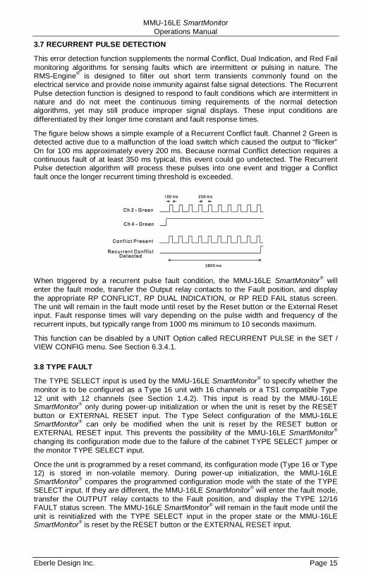
The figure below shows a simple example of a Recurrent Conflict fault. Channel 2 Green is detected active due to a malfunction of the load switch which caused the output to “flicker” On for 100 ms approximately every 200 ms. Because normal Conflict detection requires a continuous fault of at least 350 ms typical, this event could go undetected. The Recurrent Pulse detection algorithm will process these pulses into one event and trigger a Conflict fault once the longer recurrent timing threshold is exceeded.
When triggered by a recurrent pulse fault condition, the MMU-16LE SmartMonitor® will enter the fault mode, transfer the Output relay contacts to the Fault position, and display the appropriate RP CONFLICT, RP DUAL INDICATION, or RP RED FAIL status screen. The unit will remain in the fault mode until reset by the Reset button or the External Reset input. Fault response times will vary depending on the pulse width and frequency of the recurrent inputs, but typically range from 1000 ms minimum to 10 seconds maximum.
This function can be disabled by a UNIT Option called RECURRENT PULSE in the SET / VIEW CONFIG menu. See Section 6.3.4.1.
3.8 TYPE FAULT
The TYPE SELECT input is used by the MMU-16LE SmartMonitor® to specify whether the monitor is to be configured as a Type 16 unit with 16 channels or a TS1 compatible Type 12 unit with 12 channels (see Section 1.4.2). This input is read by the MMU-16LE SmartMonitor® only during power-up initialization or when the unit is reset by the RESET button or EXTERNAL RESET input. The Type Select configuration of the MMU-16LE SmartMonitor® can only be modified when the unit is reset by the RESET button or EXTERNAL RESET input. This prevents the possibility of the MMU-16LE SmartMonitor® changing its configuration mode due to the failure of the cabinet TYPE SELECT jumper or the monitor TYPE SELECT input.
Once the unit is programmed by a reset command, its configuration mode (Type 16 or Type 12) is stored in non-volatile memory. During power-up initialization, the MMU-16LE SmartMonitor® compares the programmed configuration mode with the state of the TYPE SELECT input. If they are different, the MMU-16LE SmartMonitor® will enter the fault mode, transfer the OUTPUT relay contacts to the Fault position, and display the TYPE 12/16 FAULT status screen. The MMU-16LE SmartMonitor® will remain in the fault mode until the unit is reinitialized with the TYPE SELECT input in the proper state or the MMU-16LE SmartMonitor® is reset by the RESET button or the EXTERNAL RESET input.
MMU-16LE SmartMonitor Operations Manual
Eberle Design Inc. Page 16
3.9 FIELD CHECK MONITORING
Field Check Monitoring is an enhanced function of the MMU-16LE SmartMonitor® that utilizes the Port 1 communications between the Controller Unit and the MMU in a TS2 Cabinet Assembly. When operating in the Type 16 mode the MMU-16LE SmartMonitor® will receive the Type 0 message from the Controller Unit (Type 1 or Type 2 CU) which contains an image of the controller output commands to the load switches. When a fault condition triggers the MMU-16LE, the Type 0 message information received while the fault condition was being timed will be used by the MMU-16LE SmartMonitor® to determine whether the sensed field signal input status corresponded to the Controller Unit output commands. This diagnostic information is then used by the Diagnostic Wizard to isolate whether the fault condition was caused by a Controller Unit malfunction or a failure in the load switch and/or field wiring. In the latter case, the Wizard then pinpoints the faulty inputs of the channels involved in the fault condition.
The Field Check Monitor function is enabled for each channel input individually (see Section 6.3.1) and provides two modes of operation, Field Check Fault and Field Check Status.
3.9.1 FIELD CHECK FAULT
In the Field Check Fault mode, when the field signal input states sensed as active or inactive by the MMU-16LE SmartMonitor® do not correspond with the data provided by the Controller Unit in the Type 0 message for 10 consecutive messages, the MMU-16LE SmartMonitor® will enter the fault mode, transfer the OUTPUT relay contacts to the Fault position, and display the FIELD CHECK FAULT status screen. The Channel Status Display will indicate the channels on which the Field Check error was detected (see Section 7.2 Channel Status Display). Bit #67 (Spare Bit #1) of the Type #129 response frame will be set to indicate a Field Check fault has been detected. The MMU-16LE SmartMonitor® will remain in the fault mode until the unit is reset by the RESET button or the EXTERNAL RESET input. The Field Check Fail Monitoring function is automatically disabled in the Type 12 mode, and in the Type 16 mode with the PORT 1 DISABLE input True (low). The Field Check Fail Monitoring function is also disabled when the RED ENABLE input is not active.
3.9.2 FIELD CHECK STATUS
The Field Check Status mode works in combination with the other fault monitoring functions of the MMU-16LE SmartMonitor® to produce additional diagnostic information about the detected fault. The Field Check Monitor function will be collecting status and timing a Field Check Fault if the sensed field signal input states do not correspond to the Type 0 message data from the Controller Unit. When a Conflict, Red Fail, Clearance Fail, or Dual Indication Fail triggers the MMU-16LE SmartMonitor®, the Channel Status Display and Main Status Display will correspond to that detected fault. If Field Check errors were detected while the fault was being timed, the Main Status Display will add the text “+ FCstatus” to the fault type, The FIELD CHECK STATUS screen will also be available. Bit #67 (Spare Bit #1) of the Type #129 response frame will be set to indicate Field Check errors have been detected.
In a simple example, channels 2 and 6 are set to active Green by the controller. Channel 8 Green is not permissive with channels 2 and 6 and becomes active due to a short circuit in the field wiring. The MMU-16LE SmartMonitor® will detect a Conflict Fault with Field Check Status on channel 8 Green. The main fault display text will show “Conflict with FC Status”. Pressing the SELECT button will then display the actual Field Check status, which in this example would show channel 8 Green only. The MMU-16LE SmartMonitor® used the Field Check function to directly pinpoint the faulty input (Channel 8 Green). Because of the Field Check status it is also known that the Controller Unit did not drive the faulty input thus was not involved in the fault.
The Diagnostic Wizard (HELP function, see Section 3.10) also uses the Field Check Status to pinpoint faulty inputs in a more direct fashion.

MMU-16LE SmartMonitor Operations Manual
Eberle Design Inc. Page 17
3.10 DIAGNOSTIC WIZARD
The built-in Diagnostic Wizard is an integral part of the Help System that provides detailed diagnostic information regarding the fault being analyzed. The Wizard provides a concise view of the signals involved in the fault, pinpoints faulty signal inputs, and provides guidance on isolating the cause of the malfunction. The Diagnostic Wizard is automatically invoked when the MMU-16LE SmartMonitor® is in the fault mode and the HELP button is pressed. It is also automatically invoked when the MMU-16LE SmartMonitor® is in the Previous Fail (PF) event log display and the HELP button is pressed.
The first step of the Diagnostic Wizard provides a simple definition of the fault type detected. It also filters the Channel Status display to a concise view of only the channels actually involved in the fault.
NEXT EXIT
Diagnostic Wizard Screen #2 Diagnostic Wizard Screen #3
HELP NEXT
Main Status Display Diagnostic Wizard Screen #1

MMU-16LE SmartMonitor Operations Manual
Eberle Design Inc. Page 18
In Type 16 mode, the next steps pinpoint known faulty signals. Type 12 operation does not have the benefit of Field Checking (screen #2) unless the Type 12 with SDLC mode (Section 1.4.2.1) is selected, so the MMU-16LE SmartMonitor® does not have enough information to actually identify the faulty signals. The last step offers the technician several suggestions for the cause of the malfunction.
Pressing the HELP button or the NEXT button will sequence the display through this series of steps. At any point the EXIT button will return the display back to the normal display mode. The figures above show a simple example of the Diagnostic Wizard screens for a Conflict fault.
3.11 FLASHING YELLOW ARROW PROTECTED-PERMISSIVE MONITORING (FYA)
The MMU-16LE SmartMonitor® is designed to monitor an intersection with up to four approaches using the four section Flashing Yellow Arrow (FYA) movement outlined by the NCHRP Research Project 3-54 on Protected/Permissive signal displays with Flashing Yellow Arrows. For monitoring purposes an FYA approach is logically defined as a four input “channel” consisting of the solid Red Arrow, solid Yellow Arrow, flashing Yellow Arrow (permissive), and solid Green Arrow (protected).
- NOTE -
EDI does not provide any guidelines, warrants, or recommendations for the use of protected/permissive left-turn phasing. The underlying assumption is that the traffic engineer has decided that this form of protected/permissive control is the most appropriate left-turn treatment, and all necessary considerations have been made. Until official rulemaking action by the MUTCD has occurred, the operation and functional parameters of the MMU-16LE SmartMonitor® FYA and FYAc modes are subject to change.
Two cabinet configurations are supported for both the MMU Type 16 and Type 12 modes depending on the number of load switches provided and the capabilities of the Controller Unit. A Flashing Yellow Arrow approach is actually monitored using two physical channels of the MMU-16LE SmartMonitor®. In the basic FYA mode of the unit, one additional load switch is required for each FYA approach to be monitored. Thus a TS-2 cabinet providing four vehicle phases, four pedestrian phases, and four FYA approaches would require sixteen load switches. The compact FYAc mode requires the Controller Unit to remap the Yellow outputs of the pedestrian load switches to drive the protected Green Arrow signals of the FYA approaches. In this mode the cabinet can provide the four FYA approaches with the existing twelve position back panel. Configuration settings are described in Section 6.3.14.
In the description of the two modes below, channel numbers are shown for the Type 16 TS-2 mode of the MMU-16LE SmartMonitor®. Channel numbers shown in brackets “[ ]” refer to the respective channels when operating in the Type 12 TS-1 mode (see Section 1.4.2).
3.11.1 BASIC FYA MODE
The cabinet must be wired such that for each FYA approach, the solid Green protected Arrow is driven by a load switch monitored on channels 1, 3, 5, and 7. The associated solid Red Arrow, solid Yellow Arrow, and flashing Yellow Arrow (FYA Overlap phase) must be driven by a load switch monitored on channels 13, 14, 15, and 16 [9, 10, 11, 12] respectively. The MMU-16LE SmartMonitor® associates channel 1 with 13 [9], channel 3 with 14 [10], channel 5 with 15 [11], and channel 7 with 16 [12] when FYA monitoring is enabled for that respective approach.
If a channel pair is enabled for FYA operation, the MMU-16LE SmartMonitor® will monitor the FYA logical channel pair for the following fault conditions:
a. Conflict

MMU-16LE SmartMonitor Operations Manual
Eberle Design Inc. Page 19
i. Channel conflicts are detected based on the Permissive programming jumpers on the Program Card for each channel. This operation remains unchanged from normal Nema operation.
b. Red Fail i. A Red Fail fault will occur if the solid Red Arrow AND solid Yellow
Arrow AND flashing Yellow Arrow AND solid Green Arrow all remain inactive for the Red Fail fault response time. The fault icon () will be displayed for both channels of the pair. The Red and Yellow inputs for channels 1, 3, 5, 7 do not affect the Red Fail condition for the FYA channels 13, 14, 15, 16 [9, 10, 11, 12].
c. Dual Indication i. A Dual Indication fault will occur if any two or more of the solid Red
Arrow, solid Yellow Arrow, flashing Yellow Arrow, or solid Green Arrow signal combinations are active simultaneously for the Dual Indication fault response time. The fault icon () will be displayed for the FYA channel 13, 14, 15, 16 [9, 10, 11, 12]. The fault icon () will also be displayed for the solid Green Arrow channel (1, 3, 5, 7) IF the solid Green Arrow was active.
ii. If the RG, RY, or GY Dual Indication function is enabled for the solid Green Arrow channels (1, 3, 5, 7) then a Dual Indication fault will occur if any two or more of the Red, Yellow, or solid Green Arrow inputs (1, 3, 5, 7) are active simultaneously for the Dual Indication fault response time.
d. Clearance i. A Clearance fault will be detected if the channel pair sequences from
the solid Green Arrow (1, 3, 5, 7) to the solid Red Arrow (13, 14, 15, 16 [9, 10, 11, 12]) without a minimum clearance time on the solid Yellow Arrow (13, 14, 15, 16 [9, 10, 11, 12]). The fault icon () will be displayed for the FYA channel (13, 14, 15, 16 [9, 10, 11, 12]).
ii. A Clearance fault will be detected if the FYA channel sequences from the flashing Yellow Arrow (13, 14, 15, 16 [9, 10, 11, 12]) to the solid Red Arrow (13, 14, 15, 16 [9, 10, 11, 12]) without a minimum clearance time on the solid Yellow Arrow (13, 14, 15, 16 [9, 10, 11, 12]). The fault icon () will be displayed for the FYA channel (13, 14, 15, 16 [9, 10, 11, 12]).
iii. A Clearance fault will be detected if the Green Arrow (1, 3, 5, 7) channel sequences from the solid Green Arrow (1, 3, 5, 7) to the solid Red Arrow (1, 3, 5, 7) without a minimum clearance time on the solid Yellow Arrow (1, 3, 5, 7). The fault icon () will be displayed for the solid Green Arrow channel (1, 3, 5, 7).
3.11.2 COMPACT FYAC MODE
3.11.2.1 FYAC TYPE 16 MODE
The Compact FYAc mode requires that the protected Green arrow signals be driven by the unused Ped Yellow load switch outputs on channels 9, 10, 11, and 12. In the Type 16 mode, the MMU-16LE SmartMonitor® will automatically remap the channel 9, 10, 11, and 12 Yellow physical inputs to logical channel 13, 14, 15, and 16 Green status. The associated solid Red Arrow, solid Yellow Arrow, and flashing Yellow Arrow (FYA Overlap phase) must be driven by a load switch monitored on channels 1, 3, 5, and 7 respectively. The MMU-16LE SmartMonitor® associates channel 1 with 13, channel 3 with 14, channel 5 with 15, and channel 7 with 16 when FYA monitoring is enabled for that respective approach.
Note: Using the Compact FYAc mode allows a standard twelve position load bay to provide the necessary signals without the addition of load switches for the FYA approaches. The automatic remapping of the channel 9, 10, 11, and 12 Yellow inputs by the MMU-16LE SmartMonitor® then eliminates the need to modify cabinet wiring. This mode requires that

MMU-16LE SmartMonitor Operations Manual
Eberle Design Inc. Page 20
the Controller Unit be capable of remapping the Protected Green Arrow signal driver to the channel 9, 10, 11, and 12 Yellow load switch inputs.
If a channel pair is enabled for FYAc operation, the MMU-16LE SmartMonitor® will monitor the FYA logical channel pair for the following fault conditions:
a. Conflict i. Channel conflicts are detected based on the Permissive programming
jumpers on the Program Card for each channel. This operation remains unchanged from normal Nema operation.
b. Red Fail i. A Red Fail fault will occur if the solid Red Arrow AND solid Yellow
Arrow AND flashing Yellow Arrow AND solid Green Arrow all remain inactive for the Red Fail fault response time. The fault icon () will be displayed for both channels of the pair. The Red and Yellow inputs for channels 13, 14, 15, 16 do not affect the Red Fail condition for the FYAc channels 13, 14, 15, 16.
c. Dual Indication i. A Dual Indication fault will occur if any two or more of the solid Red
Arrow, solid Yellow Arrow, flashing Yellow Arrow, or solid Green Arrow signal combinations are active simultaneously for the Dual Indication fault response time. The fault icon () will be displayed for the FYAc channel 1, 3, 5, 7. The fault icon () will also be displayed for the solid Green Arrow channel (13, 14, 15, 16) IF the solid Green Arrow was active.
ii. If the RG, RY, or GY Dual Indication function is enabled for the solid Green Arrow channels (13, 14, 15, 16) then a Dual Indication fault will occur if any two or more of the Red, Yellow, or solid Green Arrow inputs (13, 14, 15, 16) are active simultaneously for the Dual Indication fault response time.
d. Clearance i. A Clearance fault will be detected if the FYAc channel pair sequences
from the solid Green Arrow (13, 14, 15, 16) to the solid Red Arrow (1, 3, 5, 7) without a minimum clearance time on the solid Yellow Arrow (1, 3, 5, 7). The fault icon () will be displayed for the FYAc channel (1, 3, 5, 7).
ii. A Clearance fault will be detected if the FYAc channel sequences from the flashing Yellow Arrow (1, 3, 5, 7) to the solid Red Arrow (1, 3, 5, 7) without a minimum clearance time on the solid Yellow Arrow (1, 3, 5, 7). The fault icon () will be displayed for the FYAc channel (1, 3, 5, 7).
iii. A Clearance fault will be detected if the Green Arrow (13, 14, 15, 16) channel sequences from the solid Green Arrow (13, 14, 15, 16) to the Red (13, 14, 15, 16) without a minimum clearance time on the Yellow (13, 14, 15, 16). The fault icon () will be displayed for the solid Green Arrow channel (13, 14, 15, 16).
3.11.2.2 FYAC TYPE 12 MODE
The cabinet must be wired such that for each FYA approach, the solid Green protected Arrow is driven by a load switch monitored on channels 9, 10, 11, and 12. The associated solid Red Arrow, solid Yellow Arrow, and flashing Yellow Arrow (FYA Overlap phase) must be driven by a load switch monitored on channels 1, 3, 5, and 7 respectively. The MMU-16LE SmartMonitor® associates channel 1 with 9, channel 3 with 10, channel 5 with 11, and channel 7 with 12, when FYA monitoring is enabled for that respective approach.
Note: Using the Compact FYAc mode allows a standard twelve position load bay to provide the necessary signals without the addition of load switches for the FYA approaches. This mode requires that the Controller Unit be capable of remapping the Protected Green Arrow signal driver to the channel 9, 10, 11, and 12 Yellow load switch inputs. The cabinet must be (re)wired such that the outputs of the Ped Yellow load switches are monitored by channels 9, 10, 11, and 12 Green of the SmartMonitor®.

MMU-16LE SmartMonitor Operations Manual
Eberle Design Inc. Page 21
If a channel pair is enabled for FYAc operation, the MMU-16LE SmartMonitor® will monitor the FYA logical channel pair for the following fault conditions:
a. Conflict i. Channel conflicts are detected based on the Permissive programming
jumpers on the Program Card for each channel. This operation remains unchanged from normal Nema operation.
b. Red Fail i. A Red Fail fault will occur if the solid Red Arrow AND solid Yellow
Arrow AND flashing Yellow Arrow AND solid Green Arrow all remain inactive for the Red Fail fault response time. The fault icon () will be displayed for both channels of the pair. The Red and Yellow inputs for channels 9, 10, 11, 12 do not affect the Red Fail condition for the FYAc channels 1, 3, 5, 7.
c. Dual Indication i. A Dual Indication fault will occur if any two or more of the solid Red
Arrow, solid Yellow Arrow, flashing Yellow Arrow, or solid Green Arrow signal combinations are active simultaneously for the Dual Indication fault response time. The fault icon () will be displayed for the FYAc channel 1, 3, 5, 7. The fault icon () will also be displayed for the solid Green Arrow channel (9, 10, 11, 12) IF the solid Green Arrow was active.
ii. If the RG, RY, or GY Dual Indication function is enabled for the solid Green Arrow channels (9, 10, 11, 12) then a Dual Indication fault will occur if any two or more of the Red, Yellow, or solid Green Arrow inputs (9, 10, 11, 12) are active simultaneously for the Dual Indication fault response time.
d. Clearance i. A Clearance fault will be detected if the FYAc channel pair sequences
from the solid Green Arrow (9, 10, 11, 12) to the solid Red Arrow (1, 3, 5, 7) without a minimum clearance time on the solid Yellow Arrow (1, 3, 5, 7). The fault icon () will be displayed for the FYAc channel (1, 3, 5, 7).
ii. A Clearance fault will be detected if the FYAc channel sequences from the flashing Yellow Arrow (1, 3, 5, 7) to the solid Red Arrow (1, 3, 5, 7) without a minimum clearance time on the solid Yellow Arrow (1, 3, 5, 7). The fault icon () will be displayed for the FYAc channel (1, 3, 5, 7).
iii. A Clearance fault will be detected if the Green Arrow (9, 10, 11, 12) channel sequences from the solid Green Arrow (9, 10, 11, 12) to the Red (9, 10, 11, 12) without a minimum clearance time on the Yellow (9, 10, 11, 12). The fault icon () will be displayed for the solid Green Arrow channel (9, 10, 11, 12).
3.11.3 FYA CHANNEL ASSIGNMENT DIAGRAMS
Type 16 TS-2 Mode
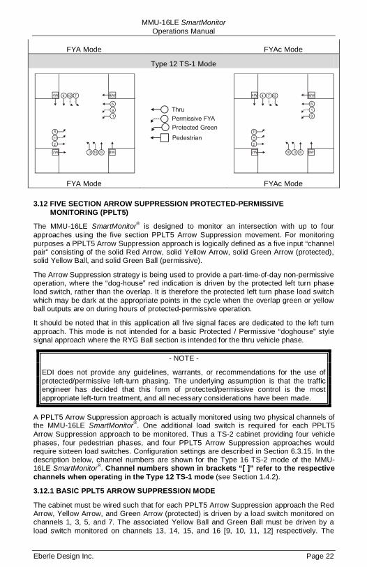
MMU-16LE SmartMonitor Operations Manual
Eberle Design Inc. Page 22
FYA Mode FYAc Mode
Type 12 TS-1 Mode
FYA Mode FYAc Mode
3.12 FIVE SECTION ARROW SUPPRESSION PROTECTED-PERMISSIVE MONITORING (PPLT5)
The MMU-16LE SmartMonitor® is designed to monitor an intersection with up to four approaches using the five section PPLT5 Arrow Suppression movement. For monitoring purposes a PPLT5 Arrow Suppression approach is logically defined as a five input “channel pair” consisting of the solid Red Arrow, solid Yellow Arrow, solid Green Arrow (protected), solid Yellow Ball, and solid Green Ball (permissive).
The Arrow Suppression strategy is being used to provide a part-time-of-day non-permissive operation, where the “dog-house” red indication is driven by the protected left turn phase load switch, rather than the overlap. It is therefore the protected left turn phase load switch which may be dark at the appropriate points in the cycle when the overlap green or yellow ball outputs are on during hours of protected-permissive operation.
It should be noted that in this application all five signal faces are dedicated to the left turn approach. This mode is not intended for a basic Protected / Permissive “doghouse” style signal approach where the RYG Ball section is intended for the thru vehicle phase.
- NOTE -
EDI does not provide any guidelines, warrants, or recommendations for the use of protected/permissive left-turn phasing. The underlying assumption is that the traffic engineer has decided that this form of protected/permissive control is the most appropriate left-turn treatment, and all necessary considerations have been made.
A PPLT5 Arrow Suppression approach is actually monitored using two physical channels of the MMU-16LE SmartMonitor®. One additional load switch is required for each PPLT5 Arrow Suppression approach to be monitored. Thus a TS-2 cabinet providing four vehicle phases, four pedestrian phases, and four PPLT5 Arrow Suppression approaches would require sixteen load switches. Configuration settings are described in Section 6.3.15. In the description below, channel numbers are shown for the Type 16 TS-2 mode of the MMU-16LE SmartMonitor®. Channel numbers shown in brackets “[ ]” refer to the respective channels when operating in the Type 12 TS-1 mode (see Section 1.4.2).
3.12.1 BASIC PPLT5 ARROW SUPPRESSION MODE
The cabinet must be wired such that for each PPLT5 Arrow Suppression approach the Red Arrow, Yellow Arrow, and Green Arrow (protected) is driven by a load switch monitored on channels 1, 3, 5, and 7. The associated Yellow Ball and Green Ball must be driven by a load switch monitored on channels 13, 14, 15, and 16 [9, 10, 11, 12] respectively. The
MMU-16LE SmartMonitor Operations Manual
Eberle Design Inc. Page 23
MMU-16LE SmartMonitor® associates channel 1 with 13 [9], channel 3 with 14 [10], channel 5 with 15 [11], and channel 7 with 16 [12] when PPLT5 Arrow Suppression monitoring is enabled for that respective approach.
If a channel pair is enabled for PPLT5 Arrow Suppression operation, the MMU-16LE SmartMonitor® will monitor the PPLT5 Arrow Suppression logical channel pair for the following fault conditions:
a. Conflict i. Channel conflicts are detected based on the Permissive programming
jumpers on the Program Card for each channel. This operation remains unchanged from normal Nema operation.
b. Red Fail i. A Red Fail fault will occur if the Red Arrow AND Yellow Arrow AND Green
Arrow AND Yellow Ball AND Green Ball all remain inactive for the Red Fail fault response time. The fault icon () will be displayed for both channels of the pair. The unused Red Ball input for channels 13, 14, 15, 16 [9, 10, 11, 12] does not affect the Red Fail condition.
c. Dual Indication i. A Dual Indication fault will occur if any two or more of the Red Arrow,
Yellow Arrow, or Green Arrow (1, 3, 5, 7) signal combinations are active simultaneously for the Dual Indication fault response time. The fault icon () will be displayed for the channel 1, 3, 5, 7.
ii. If the RG or RY Dual Indication function is enabled for the Yellow and Green Ball channels 13, 14, 15, 16 [9, 10, 11, 12] then a Dual Indication fault will occur if any two or more of the Red Arrow (1, 3, 5, 7), and Yellow Ball or Green Ball inputs (13, 14, 15, 16 [9, 10, 11, 12]) are active simultaneously for the Dual Indication fault response time. The fault icon () will be displayed for both channels of the pair.
iii. If the GY Dual Indication function is enabled for the Yellow and Green Ball channels 13, 14, 15, 16 [9, 10, 11, 12] then a Dual Indication fault will occur if the Yellow Ball and Green Ball inputs (13, 14, 15, 16 [9, 10, 11, 12]) are active simultaneously for the Dual Indication fault response time. The fault icon () will be displayed for the channel 13, 14, 15, 16 [9, 10, 11, 12].
d. Clearance i. A Clearance fault will be detected if the channel 1, 3, 5, 7 sequences
from the Green Arrow (1, 3, 5, 7) to the Red Arrow (1, 3, 5, 7) without a minimum clearance time on the Yellow Arrow (1, 3, 5, 7). The fault icon () will be displayed for the channel (1, 3, 5, 7).
ii. A Clearance fault will be detected if the channel 13, 14, 15, 16 [9, 10, 11, 12] sequences from the Green Ball (13, 14, 15, 16 [9, 10, 11, 12]) to the Red Arrow (1, 3, 5, 7) without a minimum clearance time on the Yellow Ball (13, 14, 15, 16 [9, 10, 11, 12]). The fault icon () will be displayed for the channel (13, 14, 15, 16 [9, 10, 11, 12]).
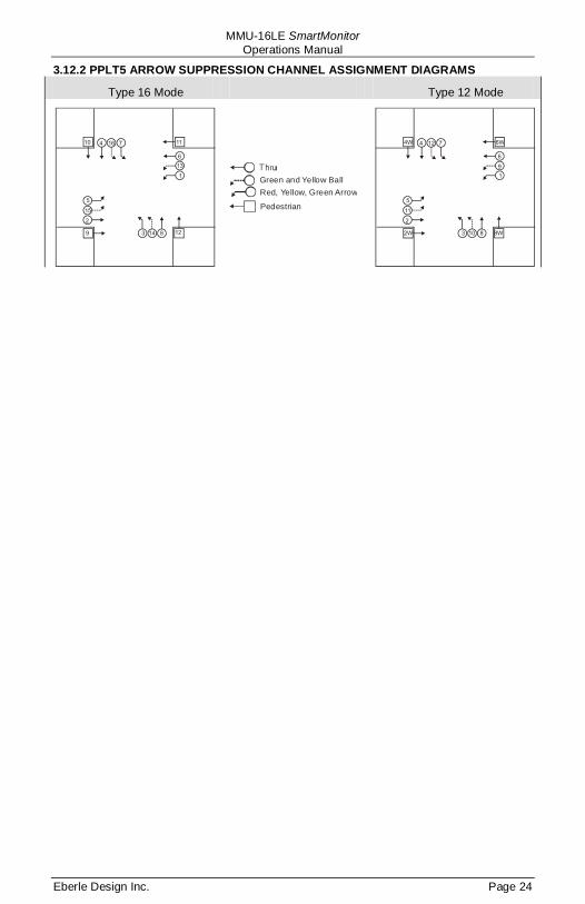
MMU-16LE SmartMonitor Operations Manual
Eberle Design Inc. Page 24
3.12.2 PPLT5 ARROW SUPPRESSION CHANNEL ASSIGNMENT DIAGRAMS
Type 16 Mode Type 12 Mode
Green and Yellow BallRed, Yellow, Green Arrow
Pedestrian

MMU-16LE SmartMonitor Operations Manual
Eberle Design Inc. Page 25
Section 4 ECcom Interface
4.1 EDI ECCOM MONITOR REPORTS
The EDI ECcom software package (Version 3.5.8 or greater is required) interfaces a Computer or System to the MMU-16LE. The ECcom program will display the Status (S), Previous Fault (PF) event log, AC Line (AC) event log, Manual Reset (MR) event log, Configuration (CF) event log, and Signal Sequence logs. All events are time stamped with the time and date of the event.
Operation of the ECcom software package is described in EDI ECcom Software Operations Manual and will not be covered in this manual. The EDI ECcom software is available at no charge from the EDI web site at www.EDItraffic.com.
4.1.1 GENERAL DATA
Monitor ID#: a four digit (0000-9999) ID number may be assigned to the monitor.
Monitor Name: a thirty character name may be assigned to the monitor.
Time and Date: each event is marked with the time and date of occurrence.
Event Number
4.1.2 CURRENT STATUS (S)
: identifies the record number in the log. Event #1 is the most recent event.
Fault Type: the fault type description.
Field Status: the current or latched RYGW field status and RMS voltages.
Cabinet Temperature: the current or latched temperature if the monitor.
AC Line Voltage: the current or latched AC Line voltage and frequency.
Control Input Status
4.1.3 PREVIOUS FAULT (PF) EVENT LOG
: the current or latched state and RMS voltage of the Red Enable input and Load Switch Flash bit.
Fault Type: the fault type description.
Field Status: the latched field status, RMS voltages, and fault channel status at the time of the fault.
Cabinet Temperature: the latched temperature at the time of the fault.
AC Line Voltage: the AC Line voltage and frequency at the time of the fault.
Control Input Status
4.1.4 AC LINE (AC) EVENT LOG
: the latched state and RMS voltage of the Red Enable input and Load Switch Flash bit.
Event Type: describes the type of AC Line event that occurred.
Power-up: AC on, monitor performed a cold start
Brown-out: AC Line < drop-out level
Restore: AC restored from AC brown-out or AC interruption, no cold start
AC Line Voltage
: the AC Line voltage at the time of the event.
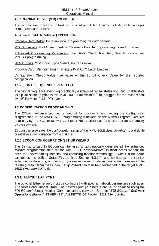
MMU-16LE SmartMonitor Operations Manual
Eberle Design Inc. Page 26
4.1.5 MANUAL RESET (MR) EVENT LOG
The monitor was reset from a fault by the front panel Reset button or External Reset input or non-latched fault clear.
4.1.6 CONFIGURATION (CF) EVENT LOG
Program Card Matrix: the permissive programming for each channel.
MYCD Jumpers: the Minimum Yellow Clearance Disable programming for each channel.
Enhanced Programming Parameters: Unit, Field Check, Red Fail, Dual Indication, and MYRCD programming
NEMA Inputs: 24V Inhibit, Type Select, Port 1 Disable.
Program Card: Minimum Flash Timing, 24V & CVM Latch Enables.
Configuration Check Value
4.1.7 SIGNAL SEQUENCE EVENT LOG
: the value of the 16 bit Check Value for the reported configuration.
The Signal Sequence event log graphically displays all signal states and Red Enable state for up 30 seconds prior to the MMU-16LE SmartMonitor® fault trigger for the most recent five (5) Previous Fault (PF) events.
4.2 CONFIGURATION PROGRAMMING
The ECcom software provides a method for displaying and setting the configuration programming of the MMU-16LE. Programming functions on the Nema Program Card are read only by the ECcom software. All other Nema enhanced functions can be set directly by the software.
ECcom can also save the configuration setup of the MMU-16LE SmartMonitor® to a disk file or retrieve a configuration from a disk file.
4.2.1 ECCOM CONFIGURATION SET-UP WIZARD
The Set-up Wizard in ECcom can be used to automatically generate all the enhanced monitor programming data for the MMU-16LE SmartMonitor® in most cases without the need for understanding complex and confusing monitor terminology. It works in the same fashion as the built-in Setup Wizard (see Section 6.3.14), and configures the monitor enhanced-feature programming using a simple series of intersection related questions. The resulting output from the ECcom Setup Wizard can then be downloaded to the target MMU-16LE SmartMonitor® unit.
4.3 ETHERNET LAN PORT
The optional Ethernet port must be configured with specific network parameters such as an IP address and Subnet Mask. The network port parameters are set or changed using the EDI ECcom® Signal Monitor Communications software. See the "EDI ECcom® Software Operations Manual" ETHERNET LAN SETTINGS Section 3.2.1.2 for details.
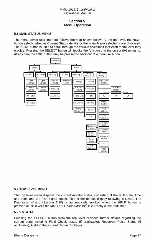
MMU-16LE SmartMonitor Operations Manual
Eberle Design Inc. Page 27
Section 5 Menu Operation
5.1 MAIN STATUS MENU
The menu driven user interface follows the map shown below. At the top level, the NEXT button selects whether Current Status details or the main Menu selections are displayed. The NEXT button is used to scroll through the various selections that each menu level may provide. Pressing the SELECT button will invoke the function that the cursor () points to. At any time the EXIT button may be pressed to back out of a menu selection.
5.2 TOP LEVEL MENU
The top level menu displays the current monitor status, consisting of the fault state, time and date, and the field signal states. This is the default display following a Reset. The Diagnostic Wizard (Section 3.10) is automatically invoked when the HELP button is pressed at this level if the MMU-16LE SmartMonitor® is currently in the fault state.
5.2.1 STATUS
Pressing the SELECT button from the top level provides further details regarding the current state including Field Check status (if applicable), Recurrent Pulse Status (if applicable), Field Voltages, and Cabinet Voltages.
Main Status
Status
<Fault>
Signal Voltage
Cabinet Voltage
(FC Status)
(RP Status)
<No Fault>
Signal Voltage
Cabinet Voltage
Menu
View Logs
Previous Fail Log
Reset Log
AC Line Log
Set Clock
Set Clock Error
Clear Logs
All Logs
Previous Fail Log
Reset Log
AC Line Log
Config Change Log
Set-up Wizard
Unused
Ped DW
Peds
PP Turns
Review
Set
Set / View Config
Field Check Enable
Dual Ind Enable
RG RY GY
Red Fail Enable
Unit Options
View Permisives
View Pgm Card
Config Check Value
Monitor ID & Name
Firmware Version
FYA
Set-up Wizard
Y+R Clearance
Factory Default
ATSI Default

MMU-16LE SmartMonitor Operations Manual
Eberle Design Inc. Page 28
5.2.2 MENU
Pressing the NEXT button followed by the SELECT button from the top level provides the main Menu structure for selecting the following functions:
5.2.2.1 VIEW LOGS
This menu category provides a review of: Previous Failure (PF) log AC Line (AC) event log Monitor Reset (MR) log
Events are stored with #1 being the newest event in the log. Pressing the NEXT button will display the events from newest to oldest (#1 … #n). Once the last entry is displayed pressing the NEXT button will display the events from oldest to newest (#n … #1).
The Diagnostic Wizard is automatically invoked when the HELP button is pressed while reviewing the Previous Failure (PF) logs.
5.2.2.2 VIEW AND SET CONFIGURATION
This menu category provides a means to review and/or set configuration parameters:
Function View Set Field Check Enable Dual Indication Enable Red Fail Enable Unit Options Permissive Channels Program Card Options Red+Yellow Clearance Disable Monitor ID and Name Firmware Version Set-up Wizard Set Factory Default Configuration Check Value Flashing Yellow Arrow Enable PPLT5 Suppression Enable
See Section 6 for details on each item.
5.2.2.3 SET-UP WIZARD
The built-in Set-up Wizard (see Section 6.3.14) is used to generate configuration values for the following parameters:
Field Check Enable (Type 16 mode only) Red Fail Enable Dual Indication Enable (RG, YG, and GY) Minimum Yellow Plus Red Clearance
The following parameters are NOT
Unit Data
affected by the Set-up Wizard and must be manually programmed:
Permissive Matrix (Program Card jumpers) Minimum Yellow Clearance Disable (Program Card jumpers)
The permissive programming on the Program Card must still be provided for Conflict monitoring. The MMU-16LE SmartMonitor® will not exit the fault mode without the Program Card inserted.

MMU-16LE SmartMonitor Operations Manual
Eberle Design Inc. Page 29
5.2.2.4 CLEAR LOGS
This menu category provides a means to clear the following logs: Previous Failure (PF) log AC Line (AC) event log Monitor Reset (MR) log Configuration (CF) log
The ALL selection will clear all four event logs.
5.2.2.5 SET CLOCK
The built-in time of day and date clock can be set from this menu item. Note that in Type 16 mode, the Controller Unit synchronizes the clock of the MMU-16LE SmartMonitor® once per second via Port 1 SDLC communications. The day and date clock will automatically adjust for Daylight Savings time. The week and month that this occurs can be programmed via the ECcom interface (see EDI ECcom Software Operations Manual).
- WARNING -
AFTER RUNNING THE SET-UP WIZARD ALL PARAMETERS SHOULD BE REVIEWED FOR CORRECTNESS AND CONSISTENCY WITH THE CABINET
PROGRAMMING AND INTERSECTION GEOMETRY.
SOME CHANGES TO THE WIZARD RESULTS MAY BE REQUIRED DEPENDING ON CABINET WIRING OR OTHER CONSIDERATIONS.
MMU-16LE SmartMonitor Operations Manual
Eberle Design Inc. Page 30
Section 6 Installation
6.1 GENERAL
There are several ways to program the Enhanced Function configuration parameters of the MMU-16LE SmartMonitor®. Regardless of the method, the basic Nema parameters programmed on the Program Card must be set manually using soldered wire jumpers (Section 6.2). The MMU-16LE SmartMonitor® will not exit the fault mode without a Program Card installed.
The most basic method to program the Enhanced Function configuration parameters is to use the front panel menu driven interface (See Section 5.2.2.2). The user should select each and every function and provide the required input.
The EDI ECcom software can also be used to develop the configuration parameters. This is the same process as using the front panel menu driven interface but is easier due to the personal computer interface. Once a parameter database has been developed, it can be saved to a disk file for later use or for use a template. The parameter database can then be directly downloaded to the MMU-16LE SmartMonitor®.
6.2 PROGRAM CARD PROGRAMMING
The MMU-16LE SmartMonitor® uses an interchangeable Program Card which contains soldered wire jumpers to program the permissive channel pairs, Minimum Flash time, Minimum Yellow Change Disable, +24V Latch Enable, and CVM Latch Enable inputs. The special EDI Program Card provided with the unit also has a small non-volatile memory device that contains all the enhanced configuration programming not defined by the standard Nema jumpers.
When replacing the MMU-16LE SmartMonitor® for service or test purposes, all Nema standard and enhanced-feature programming is automatically transferred to the replacement unit when the EDI Program Card is inserted and the Unit Option, PGM CARD MEMORY, in the SET / VIEW CONFIG menu has been enabled.
The MMU-16LE SmartMonitor® is compatible with both a standard Nema defined Program Card and the special EDI Program Card. The special EDI Program Card is compatible with all other MMU units that comply with the Nema Publication TS2-2003 v02.06.
6.2.1 PERMISSIVE CHANNEL PROGRAMMING
The MMU-16LE SmartMonitor® Program Card contains a group of soldered wire jumper holes to set the permissive or compatible channel configuration. This programming is determined by the intersection layout and phase assignments. The card is initially supplied with 120 empty wire jumper hole pairs. This initial programming sets all channels to conflict with all other channels. To program a compatible channel pair, solder a wire jumper into the appropriate location for that channel pair as marked on the Program Card. Make sure that any jumper leads do not make contact with any other jumper lead on the card or the monitor chassis when the Programming Card is inserted into the MMU-16LE.
Example: If channel 2 Green and Yellow is PERMISSIVE with channel 4 Green and Yellow, solder a jumper wire into the jumper pair labeled "2-4".
If the Program Card is absent or not seated properly in the edge connector, the MMU-16LE SmartMonitor® will enter the fault mode, transfer the OUTPUT relay contacts to the Fault position, and display the PGM CARD AJAR status screen. The MMU-16LE SmartMonitor® will remain in the fault mode until the Program Card is correctly seated and the MMU-16LE SmartMonitor® is reset by the RESET button or the EXTERNAL RESET input.

MMU-16LE SmartMonitor Operations Manual
Eberle Design Inc. Page 31
6.2.2 MINIMUM FLASH TIME PROGRAMMING
The MMU-16LE SmartMonitor® Programming Card contains a group of soldered wire jumper holes to set the Minimum Flashing Indication time after an MMU Power Failure. The programming of the Minimum Flash time is in a binary encoded format. The addition of a soldered wire jumper in a jumper hole pair will add that designated input value to the binary weighted sum plus 1 second (minimum period is 6 seconds). This provides a programming range from 6 seconds to 16 seconds.
b8 b4 b2 b1 Delay Period Open Open Open Open 6 seconds Open Open Open Jump 6 seconds Open Open Jump Open 6 seconds Open Open Jump Jump 6 seconds Open Jump Open Open 6 seconds Open Jump Open Jump 6 seconds Open Jump Jump Open 7 seconds Open Jump Jump Jump 8 seconds Jump Open Open Open 9 seconds Jump Open Open Jump 10 seconds Jump Open Jump Open 11 seconds Jump Open Jump Jump 12 seconds Jump Jump Open Open 13 seconds Jump Jump Open Jump 14 seconds Jump Jump Jump Open 15 seconds Jump Jump Jump Jump 16 seconds
It is recommended that the Minimum Flash Time be programmed on the MMU-16LE SmartMonitor® to facilitate an orderly start-up sequence of the Cabinet Assembly upon application or restoration of AC LINE power. The amount of flash time is typically equal to the amount programmed on the Controller Unit (minimum 6 seconds). The Minimum Flash Time should be long enough to ensure all cabinet components are initialized and ready before the MMU-16LE SmartMonitor® transfers the OUTPUT relay and places the intersection into operation.
6.2.3 MINIMUM YELLOW CHANGE DISABLE PROGRAMMING
The MMU-16LE SmartMonitor® Program Card contains a group of 16 soldered wire jumper holes to disable Minimum Yellow Change Monitoring for each channel. A soldered wire jumper in a jumper hole pair will DISABLE Minimum Yellow Change Monitoring for that channel.
Minimum Yellow Change Monitoring requires activity on all three channel inputs (Green, Yellow, and Red) to detect a Minimum Yellow Change Fault. This function should be disabled for channels which do not provide a true Yellow Change interval equal to or greater than 3 seconds.
6.2.4 VOLTAGE MONITOR LATCH PROGRAMMING
The MMU-16LE SmartMonitor® Program Card contains two soldered wire jumper hole pairs to cause +24V Monitor and Controller Voltage Monitor (CVM) faults to be latching. A soldered wire jumper in the jumper hole pair labeled 24V Latch Enable will ENABLE the latching mode for +24V Monitoring. A soldered wire jumper in the jumper hole pair labeled CVM Latch Enable will ENABLE the latching mode for CVM Monitoring.
If the latch mode is enabled for either of these monitoring functions, the MMU-16LE SmartMonitor® will remain in the fault mode until the unit is reset by the RESET button or the EXTERNAL RESET input. Restoration of the proper input voltage or an MMU Power Failure will not reset the unit.
MMU-16LE SmartMonitor Operations Manual
Eberle Design Inc. Page 32
6.3 ENHANCED FUNCTION PROGRAMMING
The Program Card provides the configuration values for all required basic Nema TS-2 functions (Section 2). The MMU-16LE SmartMonitor® provides a host of additional functions that are programmed from the front panel menu interface. Alternatively, the data can be designed or downloaded from disk file using the ECcom software. All Enhanced Function programming values are simultaneously stored in the non-volatile memory on the EDI Program Card (see Section 6.3.4.6).
6.3.1 FIELD CHECK ENABLE PROGRAMMING Menu Path: MENU / SET VIEW CONFIG / FIELD CHECK ENABLE
The Field Check monitoring function (See Section 3.9) is enabled on a per input basis for each channel. The Field Check function must be enabled for the Diagnostic Wizard to directly pinpoint faulty channel inputs.
Typically any monitor input that is driven from a load switch output should have Field Check enabled. This would include the Red, Yellow, and Green inputs from a vehicle channel, The Yellow and Green inputs from a protected-permissive left turn channel, and the Red and Green inputs of a pedestrian channel.
The following list describes several examples where the Field Check function for that input should be DISABLED.
1. The Red field signal input of a channel is tied to AC LINE for the left turn channel of a four or five section signal head.
2. The Red field signal input of a channel is tied to AC LINE for an unused channel.
3. The Yellow field signal input of a pedestrian channel which is not monitoring the Yellow load switch output (e.g. no load on Yellow).
4. The Red field signal input of a pedestrian channel which is not monitoring the Don’t Walk load switch output (i.e. the Red (Don’t Walk) field signal input is tied to AC LINE).
5. A separate MMU-16LE SmartMonitor® channel is monitoring an overlap signal which is generated in hardware from another vehicle channel load switch output.
6.3.2 DUAL INDICATION ENABLE PROGRAMMING Menu Path: MENU / SET VIEW CONFIG / DUAL IND ENABLE / R-G DUAL ENABLE Menu Path: MENU / SET VIEW CONFIG / DUAL IND ENABLE / R-Y DUAL ENABLE Menu Path: MENU / SET VIEW CONFIG / DUAL IND ENABLE / G-Y DUAL ENABLE
The Dual Indication monitoring function (See Section 3.2) is enabled on a per channel basis for each combination of Dual Indication monitoring; Red+Green, Red+Yellow, and Green+Yellow. When Dual Indication monitoring is enabled for a channel, the MMU-16LE SmartMonitor® will enter the fault mode when it has detected more than one active input on that channel. Dual Indication monitoring is typically not enabled for monitor channels that are not used, or channels that have the Red input (protected / permissive left turn) tied to AC Line, or pedestrian channels with the Don’t Walk (Red) input tied to AC Line.
6.3.3 RED FAIL ENABLE PROGRAMMING
Menu Path: MENU / SET VIEW CONFIG / RED FAIL ENABLE
The Red Fail monitoring function (See Section 2.2) is enabled on a per channel basis. When Red Fail monitoring is enabled for a channel, the MMU-16LE SmartMonitor® will enter the fault mode when it does not detect at least one active input on a channel. Red Fail monitoring is typically not enabled for monitor channels that are not used, or channels that do not have an active Red input (protected / permissive left turn), or pedestrian channels with no active Yellow input.

MMU-16LE SmartMonitor Operations Manual
Eberle Design Inc. Page 33
6.3.4 UNIT OPTION PROGRAMMING Menu Path: MENU / SET VIEW CONFIG / UNIT OPTIONS
The MMU-16LE SmartMonitor® provides a set of independently programmed options which assist in configuring the MMU-16LE SmartMonitor® to various wiring or operating conventions in the cabinet.
6.3.4.1 RECURRENT PULSE OPTION
The Recurrent Pulse Detection function is DISABLED by setting RECURRENT PULSE to the OFF state. See Section 3.7. The Factory Default setting is ON.
6.3.4.2 WALK DISABLE OPTION
The Walk Disable function is ENABLED by setting the by setting WALK DISABLE to the ON state. See Section 2.2.2 and . The Factory Default setting is OFF.
6.3.4.3 LOG CVM FAULTS OPTION
The CVM Logging function is DISABLED by setting LOG CVM FAULTS to the OFF state. See Section 2.3.2.2. The Factory Default setting is ON.
6.3.4.4 EXTERNAL WATCHDOG ENABLE OPTION
The External Watchdog Monitoring function is ENABLED by setting EXTERN WATCHDOG to the ON state. See Section 3.3. The Factory Default setting is OFF.
6.3.4.5 +24V-II = 12 VDC ENABLE OPTION
Setting the +24VDC Monitor II threshold to 12 Volts DC is ENABLED by setting +24V-2 = 12Vdc to the ON state. See Section 2.3.1.3. The Factory Default setting is OFF.
6.3.4.6 PROGRAM CARD MEMORY ENABLE OPTION
The nonvolatile memory interface on the EDI Program Card is ENABLED by setting PGM CARD MEMORY to the ON state. See Section 1.2.4. The Factory Default setting is OFF.
6.3.4.7 LEDGUARD® ENABLE OPTION
The LEDguard® Monitoring function is ENABLED by setting LEDguard to the ON state. See Section 1.4.1. The Factory Default setting is OFF.
6.3.4.8 FORCE TYPE 16 MODE ENABLE OPTION
The Force Type 16 mode can be ENABLED by setting FORCE TYPE 16 to the ON state. See Section 1.4.2.2. The Factory Default setting is OFF.
6.3.4.9 TYPE 12 WITH SDLC MODE ENABLE OPTION
The Port 1 SDLC operation can be ENABLED in the TYPE 12 mode by setting TYPE 12 WITH SDLC to the ON state. See Section 1.4.2.1. The Factory Default setting is OFF.
6.3.5 VIEW PERMISSIVES Menu Path: MENU / SET VIEW CONFIG / PERMISSVES
The permissive programming defined by the soldered jumpers on the Program Card can be reviewed for each Primary channel 1:15. The Main Status display will show the Primary channel number which is also indicated by the ▼ symbol on the Channel Status display. All Secondary channels programmed permissive (jumper installed) with the displayed primary channel will be indicated on the Channel Status display with their and icons illuminated. Pressing the NEXT button will increment the display to the next Primary channel.
These settings are read-only and require the Program Card jumpers to be changed.
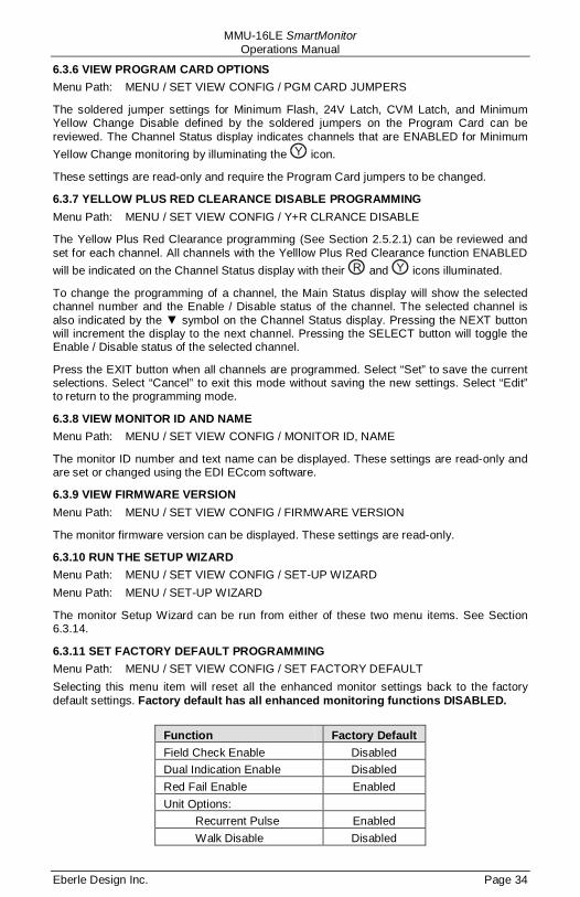
MMU-16LE SmartMonitor Operations Manual
Eberle Design Inc. Page 34
6.3.6 VIEW PROGRAM CARD OPTIONS Menu Path: MENU / SET VIEW CONFIG / PGM CARD JUMPERS
The soldered jumper settings for Minimum Flash, 24V Latch, CVM Latch, and Minimum Yellow Change Disable defined by the soldered jumpers on the Program Card can be reviewed. The Channel Status display indicates channels that are ENABLED for Minimum Yellow Change monitoring by illuminating the icon.
These settings are read-only and require the Program Card jumpers to be changed.
6.3.7 YELLOW PLUS RED CLEARANCE DISABLE PROGRAMMING Menu Path: MENU / SET VIEW CONFIG / Y+R CLRANCE DISABLE
The Yellow Plus Red Clearance programming (See Section 2.5.2.1) can be reviewed and set for each channel. All channels with the Yelllow Plus Red Clearance function ENABLED will be indicated on the Channel Status display with their and icons illuminated.
To change the programming of a channel, the Main Status display will show the selected channel number and the Enable / Disable status of the channel. The selected channel is also indicated by the ▼ symbol on the Channel Status display. Pressing the NEXT button will increment the display to the next channel. Pressing the SELECT button will toggle the Enable / Disable status of the selected channel.
Press the EXIT button when all channels are programmed. Select “Set” to save the current selections. Select “Cancel” to exit this mode without saving the new settings. Select “Edit” to return to the programming mode.
6.3.8 VIEW MONITOR ID AND NAME Menu Path: MENU / SET VIEW CONFIG / MONITOR ID, NAME
The monitor ID number and text name can be displayed. These settings are read-only and are set or changed using the EDI ECcom software.
6.3.9 VIEW FIRMWARE VERSION Menu Path: MENU / SET VIEW CONFIG / FIRMWARE VERSION
The monitor firmware version can be displayed. These settings are read-only.
6.3.10 RUN THE SETUP WIZARD Menu Path: MENU / SET VIEW CONFIG / SET-UP WIZARD Menu Path: MENU / SET-UP WIZARD
The monitor Setup Wizard can be run from either of these two menu items. See Section 6.3.14.
6.3.11 SET FACTORY DEFAULT PROGRAMMING Menu Path: MENU / SET VIEW CONFIG / SET FACTORY DEFAULT Selecting this menu item will reset all the enhanced monitor settings back to the factory default settings. Factory default has all enhanced monitoring functions DISABLED.
Function Factory Default Field Check Enable Disabled Dual Indication Enable Disabled Red Fail Enable Enabled Unit Options:
Recurrent Pulse Enabled Walk Disable Disabled
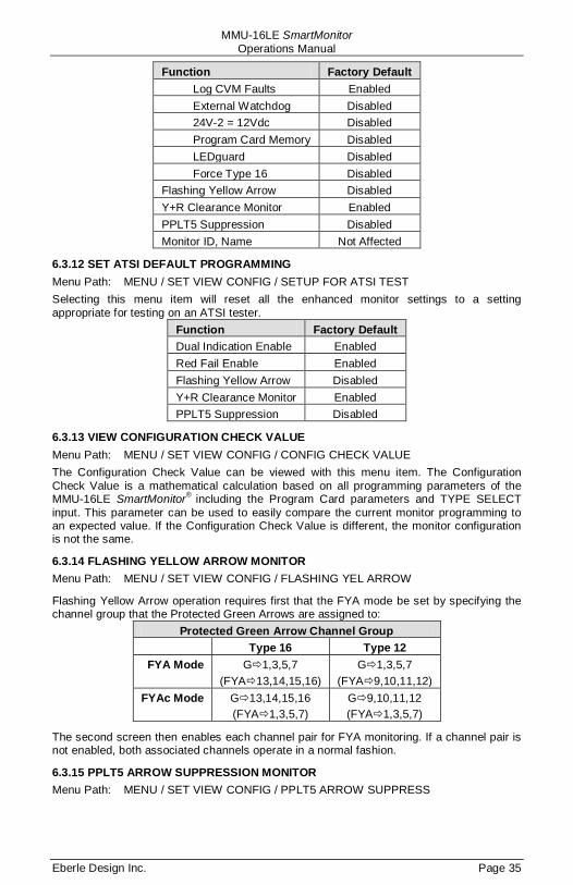
MMU-16LE SmartMonitor Operations Manual
Eberle Design Inc. Page 35
Function Factory Default Log CVM Faults Enabled External Watchdog Disabled 24V-2 = 12Vdc Disabled Program Card Memory Disabled LEDguard Disabled Force Type 16 Disabled
Flashing Yellow Arrow Disabled Y+R Clearance Monitor Enabled PPLT5 Suppression Disabled Monitor ID, Name Not Affected
6.3.12 SET ATSI DEFAULT PROGRAMMING Menu Path: MENU / SET VIEW CONFIG / SETUP FOR ATSI TEST Selecting this menu item will reset all the enhanced monitor settings to a setting appropriate for testing on an ATSI tester.
Function Factory Default Dual Indication Enable Enabled Red Fail Enable Enabled Flashing Yellow Arrow Disabled Y+R Clearance Monitor Enabled PPLT5 Suppression Disabled
6.3.13 VIEW CONFIGURATION CHECK VALUE Menu Path: MENU / SET VIEW CONFIG / CONFIG CHECK VALUE The Configuration Check Value can be viewed with this menu item. The Configuration Check Value is a mathematical calculation based on all programming parameters of the MMU-16LE SmartMonitor® including the Program Card parameters and TYPE SELECT input. This parameter can be used to easily compare the current monitor programming to an expected value. If the Configuration Check Value is different, the monitor configuration is not the same.
6.3.14 FLASHING YELLOW ARROW MONITOR Menu Path: MENU / SET VIEW CONFIG / FLASHING YEL ARROW
Flashing Yellow Arrow operation requires first that the FYA mode be set by specifying the channel group that the Protected Green Arrows are assigned to:
Protected Green Arrow Channel Group Type 16 Type 12
FYA Mode G1,3,5,7 (FYA13,14,15,16)
G1,3,5,7 (FYA9,10,11,12)
FYAc Mode G13,14,15,16 (FYA1,3,5,7)
G9,10,11,12 (FYA1,3,5,7)
The second screen then enables each channel pair for FYA monitoring. If a channel pair is not enabled, both associated channels operate in a normal fashion.
6.3.15 PPLT5 ARROW SUPPRESSION MONITOR Menu Path: MENU / SET VIEW CONFIG / PPLT5 ARROW SUPPRESS
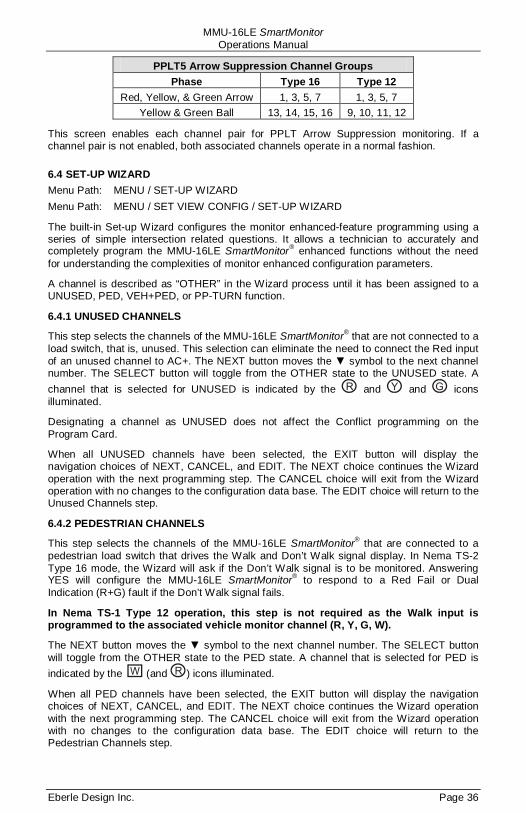
MMU-16LE SmartMonitor Operations Manual
Eberle Design Inc. Page 36
PPLT5 Arrow Suppression Channel Groups Phase Type 16 Type 12
Red, Yellow, & Green Arrow 1, 3, 5, 7 1, 3, 5, 7 Yellow & Green Ball 13, 14, 15, 16 9, 10, 11, 12
This screen enables each channel pair for PPLT Arrow Suppression monitoring. If a channel pair is not enabled, both associated channels operate in a normal fashion.
6.4 SET-UP WIZARD Menu Path: MENU / SET-UP WIZARD Menu Path: MENU / SET VIEW CONFIG / SET-UP WIZARD
The built-in Set-up Wizard configures the monitor enhanced-feature programming using a series of simple intersection related questions. It allows a technician to accurately and completely program the MMU-16LE SmartMonitor® enhanced functions without the need for understanding the complexities of monitor enhanced configuration parameters.
A channel is described as “OTHER” in the Wizard process until it has been assigned to a UNUSED, PED, VEH+PED, or PP-TURN function.
6.4.1 UNUSED CHANNELS
This step selects the channels of the MMU-16LE SmartMonitor® that are not connected to a load switch, that is, unused. This selection can eliminate the need to connect the Red input of an unused channel to AC+. The NEXT button moves the ▼ symbol to the next channel number. The SELECT button will toggle from the OTHER state to the UNUSED state. A channel that is selected for UNUSED is indicated by the and and icons illuminated.
Designating a channel as UNUSED does not affect the Conflict programming on the Program Card.
When all UNUSED channels have been selected, the EXIT button will display the navigation choices of NEXT, CANCEL, and EDIT. The NEXT choice continues the Wizard operation with the next programming step. The CANCEL choice will exit from the Wizard operation with no changes to the configuration data base. The EDIT choice will return to the Unused Channels step.
6.4.2 PEDESTRIAN CHANNELS
This step selects the channels of the MMU-16LE SmartMonitor® that are connected to a pedestrian load switch that drives the Walk and Don’t Walk signal display. In Nema TS-2 Type 16 mode, the Wizard will ask if the Don’t Walk signal is to be monitored. Answering YES will configure the MMU-16LE SmartMonitor® to respond to a Red Fail or Dual Indication (R+G) fault if the Don’t Walk signal fails.
In Nema TS-1 Type 12 operation, this step is not required as the Walk input is programmed to the associated vehicle monitor channel (R, Y, G, W).
The NEXT button moves the ▼ symbol to the next channel number. The SELECT button will toggle from the OTHER state to the PED state. A channel that is selected for PED is indicated by the (and ) icons illuminated.
When all PED channels have been selected, the EXIT button will display the navigation choices of NEXT, CANCEL, and EDIT. The NEXT choice continues the Wizard operation with the next programming step. The CANCEL choice will exit from the Wizard operation with no changes to the configuration data base. The EDIT choice will return to the Pedestrian Channels step.

MMU-16LE SmartMonitor Operations Manual
Eberle Design Inc. Page 37
6.4.3 PROTECTED-PERMISSIVE TURN CHANNELS
This step selects the channels of the MMU-16LE SmartMonitor® that are connected to a protected-permissive left turn channel load switch that drives only a Green and Yellow signal display. This selection can eliminate the need to connect the Red input of a protected-permissive turn channel to AC+. This selection can also include a right turn overlap that drives only a Green and Yellow signal display. The NEXT button moves the ▼ symbol to the next channel number. The SELECT button will toggle from the OTHER state to the PP-TURN state. A channel that is selected for PP-TURN is indicated by the and
icons illuminated.
When all PP-TURN channels have been selected, the EXIT button will display the navigation choices of NEXT, CANCEL, and EDIT. The NEXT choice continues the Wizard operation with the next programming step. The CANCEL choice will exit from the Wizard operation with no changes to the configuration data base. The EDIT choice will return to the Protected-Permissive Turn Channels step.
6.4.4 REVIEW CHANNEL ASSIGNMENTS
This step provides a review of all the channels assignments selected in the previous steps. The NEXT button moves the ▼ symbol to the next channel number. All channels should be described as VEHICLE, UNUSED, PED, VEH+PED, or PP-TURN function. When all channels have been reviewed for correctness, the EXIT button will display the navigation choices of SET, CANCEL, and EDIT. The SET choice completes the Wizard operation and sets the new configuration parameters. The CANCEL choice will exit from the Wizard operation with no changes to the configuration data base. The EDIT choice will return to the first Wizard step.
- WARNING -
AFTER RUNNING THE SET-UP WIZARD ALL PARAMETERS SHOULD BE REVIEWED FOR CORRECTNESS AND CONSISTENCY WITH THE CABINET
PROGRAMMING AND INTERSECTION GEOMETRY.
SOME CHANGES TO THE WIZARD RESULTS MAY BE REQUIRED DEPENDING ON CABINET WIRING OR OTHER CONSIDERATIONS.
MMU-16LE SmartMonitor Operations Manual
Eberle Design Inc. Page 38
Section 7 Front Panel Description
7.1 MAIN STATUS DISPLAY
The Main Status Display of the MMU-16LE SmartMonitor® is used to display the current status of the MMU-16LE SmartMonitor® and navigate the menu levels. When the monitor is not in the fault mode, the Main Status display will show current monitor status. When the monitor is in the fault mode, the Main Status display will show the latched monitor status at the time of the fault.
7.2 CHANNEL STATUS DISPLAY
Forty-eight Red , Yellow , and Green icons are provided to display the complete intersection status of the field signal inputs to the MMU-16LE SmartMonitor®. If the unit is operating normally without a fault condition present, the currently active field input signals will be displayed.
When the MMU-16LE SmartMonitor® is operating in the Type 12 mode, twelve indicators for Walk inputs are used to display active Walk inputs.
When the MMU-16LE SmartMonitor® is in the fault mode, all channels that were involved the fault will be indicated by the ▼ symbol.
7.3 FRONT PANEL LED INDICATORS
7.3.1 POWER INDICATOR
The POWER indicator will flash at a rate of 2Hz when the AC LINE voltage is below the drop-out level. It will illuminate steadily when the AC LINE voltage returns above the restore level. See Sections 2.6 and 8.1.3.
7.3.2 FAULT INDICATOR
The FAULT indicator will be illuminated whenever the MMU-16LE SmartMonitor® is in the fault mode and the OUTPUT relay has transferred to the Fault position.
7.3.3 DIAGNOSTIC INDICATOR
The DIAGNOSTIC indicator will illuminate when the MMU-16LE SmartMonitor® has detected an internal diagnostic failure. Due to the nature of these hardware/firmware failures, other indicators that may also be displayed may not be valid for trouble shooting purposes. See Section 2.8.
7.3.4 RECEIVE INDICATOR
The RECEIVE LED indicator will be pulsed each time a Port 1 SDLC message is correctly received from the Controller Unit.
7.3.5 TRANSMIT INDICATOR
The TRANSMIT LED indicator will be pulsed each time a Port 1 SDLC message is transmitted to the Controller Unit.
7.3.6 COMM INDICATOR
The COMM LED indicator will be pulsed each time an ECcom message is correctly received on the EIA-232 Port or Ethernet Port.
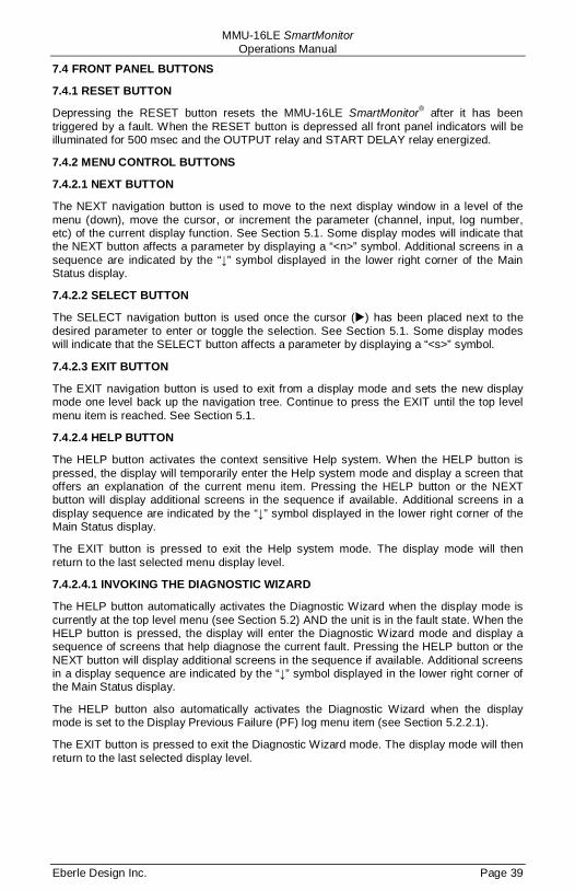
MMU-16LE SmartMonitor Operations Manual
Eberle Design Inc. Page 39
7.4 FRONT PANEL BUTTONS
7.4.1 RESET BUTTON
Depressing the RESET button resets the MMU-16LE SmartMonitor® after it has been triggered by a fault. When the RESET button is depressed all front panel indicators will be illuminated for 500 msec and the OUTPUT relay and START DELAY relay energized.
7.4.2 MENU CONTROL BUTTONS
7.4.2.1 NEXT BUTTON
The NEXT navigation button is used to move to the next display window in a level of the menu (down), move the cursor, or increment the parameter (channel, input, log number, etc) of the current display function. See Section 5.1. Some display modes will indicate that the NEXT button affects a parameter by displaying a “<n>” symbol. Additional screens in a sequence are indicated by the “↓” symbol displayed in the lower right corner of the Main Status display.
7.4.2.2 SELECT BUTTON
The SELECT navigation button is used once the cursor () has been placed next to the desired parameter to enter or toggle the selection. See Section 5.1. Some display modes will indicate that the SELECT button affects a parameter by displaying a “<s>” symbol.
7.4.2.3 EXIT BUTTON
The EXIT navigation button is used to exit from a display mode and sets the new display mode one level back up the navigation tree. Continue to press the EXIT until the top level menu item is reached. See Section 5.1.
7.4.2.4 HELP BUTTON
The HELP button activates the context sensitive Help system. When the HELP button is pressed, the display will temporarily enter the Help system mode and display a screen that offers an explanation of the current menu item. Pressing the HELP button or the NEXT button will display additional screens in the sequence if available. Additional screens in a display sequence are indicated by the “↓” symbol displayed in the lower right corner of the Main Status display.
The EXIT button is pressed to exit the Help system mode. The display mode will then return to the last selected menu display level.
7.4.2.4.1 INVOKING THE DIAGNOSTIC WIZARD
The HELP button automatically activates the Diagnostic Wizard when the display mode is currently at the top level menu (see Section 5.2) AND the unit is in the fault state. When the HELP button is pressed, the display will enter the Diagnostic Wizard mode and display a sequence of screens that help diagnose the current fault. Pressing the HELP button or the NEXT button will display additional screens in the sequence if available. Additional screens in a display sequence are indicated by the “↓” symbol displayed in the lower right corner of the Main Status display.
The HELP button also automatically activates the Diagnostic Wizard when the display mode is set to the Display Previous Failure (PF) log menu item (see Section 5.2.2.1).
The EXIT button is pressed to exit the Diagnostic Wizard mode. The display mode will then return to the last selected display level.

MMU-16LE SmartMonitor Operations Manual
Eberle Design Inc. Page 40
Section 8 Specifications
8.1 ELECTRICAL
8.1.1 POWER REQUIREMENTS Operating Line Voltage .............................................................................. 75 to 135 Vrms Operating Line Frequency .................................................................................... 60 +_Power Consumption ................................................................................... 10W (nominal)
3Hz
8.1.2 AC VOLTAGE MONITORS Nema Green Signal Inputs
No Detect .......................................................................................less than 15 Vrms Detect....................................................................................... greater than 25 Vrms
Nema Yellow Signal Inputs No Detect .......................................................................................less than 15 Vrms Detect....................................................................................... greater than 25 Vrms
Nema Walk Signal Inputs No Detect .......................................................................................less than 15 Vrms Detect....................................................................................... greater than 25 Vrms
Nema Red Signal Inputs No Detect .......................................................................................less than 50 Vrms Detect....................................................................................... greater than 70 Vrms
LEDguard® Low Threshold Signal Inputs No Detect .......................................................................................less than 15 Vrms Detect....................................................................................... greater than 25 Vrms
LEDguard® High Threshold Signal Inputs No Detect .......................................................................................less than 50 Vrms Detect....................................................................................... greater than 70 Vrms
Red Enable Input No Detect .......................................................................................less than 70 Vrms Detect....................................................................................... greater than 89 Vrms
8.1.3 POWER FAIL MONITOR AC Line Input
Dropout .......................................................................................... less than 89 Vrms Restore .....................................................................................greater than 98 Vrms
8.1.4 DC VOLTAGE MONITOR +24V MONITOR I, +24V MONITOR II
Fault ................................................................................................. less than 18 Vdc No Fault ...................................................................................... greater than 22 Vdc
+24V MONITOR II input with “24V-2 = 12 Vdc” mode selected Fault ................................................................................................... less than 9 Vdc No Fault ...................................................................................... greater than 11 Vdc
8.1.5 LOGIC INPUTS Controller Voltage Monitor (CVM), External Reset, +24V Monitor Inhibit, Port 1
Disable, Type Select, Local Flash, and External Watchdog Input True (low)........................................................................................... less than 8 Vdc False (high) ................................................................................. greater than 16 Vdc
8.2 MECHANICAL Height ............................................................................................................... 10.5 inches Width .................................................................................................................. 4.5 inches Depth .................................................................................................................. 8.5 inches
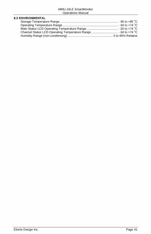
MMU-16LE SmartMonitor Operations Manual
Eberle Design Inc. Page 41
8.3 ENVIRONMENTAL Storage Temperature Range ...................................................................... -45 to +85 oC Operating Temperature Range ................................................................... -34 to +74 oC Main Status LCD Operating Temperature Range ...................................... -20 to +74 oC Channel Status LCD Operating Temperature Range ................................ -34 to +74 oC Humidity Range (non-condensing) ....................................................... 0 to 95% Relative

MMU-16LE SmartMonitor Operations Manual
Eberle Design Inc. Page 42
Section 9 Timing Functions
Conflict No Fault ...................................................................................... less than 200 msec Fault ....................................................................................... greater than 450 msec Typical ........................................................................................................ 350 msec
Red Fail No Fault ...................................................................................... less than 700 msec Fault ..................................................................................... greater than 1000 msec Typical ........................................................................................................ 850 msec
Controller Voltage Monitor (CVM) No Fault ...................................................................................... less than 125 msec Fault ....................................................................................... greater than 175 msec Typical ........................................................................................................ 150 msec
+24Vdc Monitor No Fault ...................................................................................... less than 125 msec Fault ....................................................................................... greater than 175 msec Typical ........................................................................................................ 150 msec
Local Flash Status No Fault ...................................................................................... less than 125 msec Fault ....................................................................................... greater than 175 msec Typical ........................................................................................................ 150 msec
Clearance Fail No Fault ............................................................................... greater than 2.8 second Fault .......................................................................................... less than 2.6 second Typical ...................................................................................... less than 2.7 second
Port 1 Fail Typical ........................................................................................................ 300 msec
Field Check Fail Typical ...................................................................................................... 1000 msec
Dual Indication No Fault ...................................................................................... less than 200 msec Fault ....................................................................................... greater than 500 msec Typical ........................................................................................................ 400 msec
Dual Indication (Pedestrian Channels) No Fault ...................................................................................... less than 700 msec Fault ..................................................................................... greater than 1000 msec Typical ........................................................................................................ 850 msec
MMU Power Fail Respond ................................................................................ greater than 500 msec No Response .............................................................................. less than 450 msec Minimum Flash ............................................................................. 6 to 16, +_Start Delay ........................................................................................ 2.0
1 second +_0.5 second
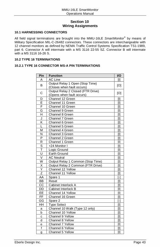
MMU-16LE SmartMonitor Operations Manual
Eberle Design Inc. Page 43
Section 10 Wiring Assignments
10.1 HARNESSING CONNECTORS
All field signal terminations are brought into the MMU-16LE SmartMonitor® by means of Military Specification MIL-C-26482 connectors. These connectors are interchangeable with 12 channel monitors as defined by NEMA Traffic Control Systems Specification TS1-1989, part 6. Connector A will intermate with a MS 3116 22-55 SZ. Connector B will intermate with a MS 3116 16-26 S.
10.2 TYPE 16 TERMINATIONS
10.2.1 TYPE 16 CONNECTOR MS-A PIN TERMINATIONS
Pin Function I/O A AC Line [I]
B Output Relay 1 Open (Stop Time) (Closes when fault occurs) [O]
C Output Relay 2 Closed (FTR Drive) (Opens when fault occurs) [O]
D Channel 12 Green [I] E Channel 11 Green [I] F Channel 10 Green [I] G Channel 9 Green [I] H Channel 8 Green [I] J Channel 7 Green [I] K Channel 6 Green [I] L Channel 5 Green [I] M Channel 4 Green [I] N Channel 3 Green [I] P Channel 2 Green [I] R Channel 1 Green [I] S +24 Monitor I [I] T Logic Ground [I] U Earth Ground [I] V AC Neutral [I] W Output Relay 1 Common (Stop Time) [I] X Output Relay 2 Common (FTR Drive) [I] Y Channel 12 Yellow [I] Z Channel 11 Yellow [I]
AA Spare 1 [-] BB Reset [I] CC Cabinet Interlock A [I] DD Cabinet Interlock B [I] EE Channel 14 Yellow [I] FF Channel 16 Green [I] GG Spare 2 [-] HH Type Select [I] a Channel 10 Walk (Type 12 only) [I] b Channel 10 Yellow [I] c Channel 9 Yellow [I] d Channel 8 Yellow [I] e Channel 7 Yellow [I] f Channel 6 Yellow [I] g Channel 5 Yellow [I]
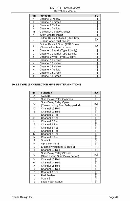
MMU-16LE SmartMonitor Operations Manual
Eberle Design Inc. Page 44
Pin Function I/O h Channel 3 Yellow [I] I Channel 15 Green [I] j Channel 2 Yellow [I] k Channel 1 Yellow [I] m Controller Voltage Monitor [I] n +24V Monitor Inhibit [I]
p Output Relay 1 Closed (Stop Time) (Opens when fault occurs) [O]
q Output Relay 2 Open (FTR Drive) (Closes when fault occurs) [O]
r Channel 12 Walk (Type 12 only) [I] s Channel 11 Walk (Type 12 only) [I] t Channel 9 Walk (Type 12 only) [I] u Channel 16 Yellow [I] v Channel 15 Yellow [I] w Channel 13 Yellow [I] x Channel 4 Yellow [I] y Channel 14 Green [I] z Channel 13 Green [I]
10.2.2 TYPE 16 CONNECTOR MS-B PIN TERMINATIONS
Pin Function I/O
A AC Line [I] B Start-Delay Relay Common [I]
C Start-Delay Relay Open (Closes during Start Delay period) [O]
D Channel 12 Red [I] E Channel 11 Red [I] F Channel 9 Red [I] G Channel 8 Red [I] H Channel 7 Red [I] J Channel 6 Red [I] K Channel 5 Red [I] L Channel 4 Red [I] M Channel 2 Red [I] N Channel 1 Red [I] P Spare 1 [-] R +24V Monitor II [I] S External Watchdog (Spare 2) [-] T Channel 13 Red [I]
U Start-Delay Relay Closed (Open during Start Delay period) [O]
V Channel 10 Red [I] W Channel 14 Red [I] X Channel 15 Red [I] Y Channel 16 Red [I] Z Channel 3 Red [I] a Red Enable [I] b Spare 3 [-] c Local Flash Status [I]
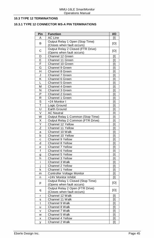
MMU-16LE SmartMonitor Operations Manual
Eberle Design Inc. Page 45
10.3 TYPE 12 TERMINATIONS
10.3.1 TYPE 12 CONNECTOR MS-A PIN TERMINATIONS
Pin Function I/O A AC Line [I]
B Output Relay 1 Open (Stop Time) (Closes when fault occurs) [O]
C Output Relay 2 Closed (FTR Drive) (Opens when fault occurs) [O]
D Channel 12 Green [I] E Channel 11 Green [I] F Channel 10 Green [I] G Channel 9 Green [I] H Channel 8 Green [I] J Channel 7 Green [I] K Channel 6 Green [I] L Channel 5 Green [I] M Channel 4 Green [I] N Channel 3 Green [I] P Channel 2 Green [I] R Channel 1 Green [I] S +24 Monitor I [I] T Logic Ground [I] U Earth Ground [I] V AC Neutral [I] W Output Relay 1 Common (Stop Time) [I] X Output Relay 2 Common (FTR Drive) [I] Y Channel 12 Yellow [I] Z Channel 11 Yellow [I] a Channel 10 Walk [I] b Channel 10 Yellow [I] c Channel 9 Yellow [I] d Channel 8 Yellow [I] e Channel 7 Yellow [I] f Channel 6 Yellow [I] g Channel 5 Yellow [I] h Channel 3 Yellow [I] i Channel 3 Walk [I] j Channel 2 Yellow [I] k Channel 1 Yellow [I] m Controller Voltage Monitor [I] n +24V Monitor Inhibit [I]
p Output Relay 1 Closed (Stop Time) (Opens when fault occurs) [O]
q Output Relay 2 Open (FTR Drive) (Closes when fault occurs) [O]
r Channel 12 Walk [I] s Channel 11 Walk [I] t Channel 9 Walk [I] u Channel 8 Walk [I] v Channel 7 Walk [I] w Channel 5 Walk [I] x Channel 4 Yellow [I] y Channel 2 Walk [I]
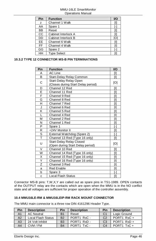
MMU-16LE SmartMonitor Operations Manual
Eberle Design Inc. Page 46
Pin Function I/O z Channel 1 Walk [I]
AA Spare 1 [-] BB Reset [I] CC Cabinet Interlock A [I] DD Cabinet Interlock B [O] EE Channel 6 Walk [I] FF Channel 4 Walk [I] GG Spare 2 [-] HH Type Select [I]
10.3.2 TYPE 12 CONNECTOR MS-B PIN TERMINATIONS
Pin Function I/O
A AC Line [I] B Start-Delay Relay Common [I]
C Start-Delay Relay Open (Closes during Start Delay period) [O]
D Channel 12 Red [I] E Channel 11 Red [I] F Channel 9 Red [I] G Channel 8 Red [I] H Channel 7 Red [I] J Channel 6 Red [I] K Channel 5 Red [I] L Channel 4 Red [I] M Channel 2 Red [I] N Channel 1 Red [I] P Spare 1 [-] R +24V Monitor II [I] S External Watchdog (Spare 2) [-] T Channel 13 Red (Type 16 only) [I]
U Start-Delay Relay Closed (Open during Start Delay period) [O]
V Channel 10 Red [I] W Channel 14 Red (Type 16 only) [I] X Channel 15 Red (Type 16 only) [I] Y Channel 16 Red (Type 16 only) [I] Z Channel 3 Red [I] a Red Enable [I] b Spare 3 [-] c Local Flash Status [I]
Connector MS-B pins: T,W,X,Y are called out as spare pins in TS1-1989. OPEN contacts of the OUTPUT relay are the contacts which are open when the MMU is in the NO conflict state and all voltages are sufficient for proper operation of the controller assembly.
10.4 MMU16LE-RM & MMU16LEIP-RM RACK MOUNT CONNECTOR
The MMU main connector is a three row DIN 4161296 Header Type.
Pin Description Pin Description Pin Description A1 AC Neutral B1 Reset C1 Logic Ground A2 Local Flash Status B2 PORT1 RxC - C2 PORT1 RxC + A3 24 Volt Inhibit B3 PORT1 RxD - C3 PORT1 RxD + A4 CVM / FM B4 PORT1 TxC - C4 PORT1 TxC +
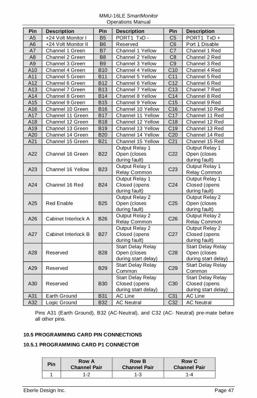
MMU-16LE SmartMonitor Operations Manual
Eberle Design Inc. Page 47
Pin Description Pin Description Pin Description A5 +24 Volt Monitor I B5 PORT1 TxD - C5 PORT1 TxD + A6 +24 Volt Monitor II B6 Reserved C6 Port 1 Disable A7 Channel 1 Green B7 Channel 1 Yellow C7 Channel 1 Red A8 Channel 2 Green B8 Channel 2 Yellow C8 Channel 2 Red A9 Channel 3 Green B9 Channel 3 Yellow C9 Channel 3 Red A10 Channel 4 Green B10 Channel 4 Yellow C10 Channel 4 Red A11 Channel 5 Green B11 Channel 5 Yellow C11 Channel 5 Red A12 Channel 6 Green B12 Channel 6 Yellow C12 Channel 6 Red A13 Channel 7 Green B13 Channel 7 Yellow C13 Channel 7 Red A14 Channel 8 Green B14 Channel 8 Yellow C14 Channel 8 Red A15 Channel 9 Green B15 Channel 9 Yellow C15 Channel 9 Red A16 Channel 10 Green B16 Channel 10 Yellow C16 Channel 10 Red A17 Channel 11 Green B17 Channel 11 Yellow C17 Channel 11 Red A18 Channel 12 Green B18 Channel 12 Yellow C18 Channel 12 Red A19 Channel 13 Green B19 Channel 13 Yellow C19 Channel 13 Red A20 Channel 14 Green B20 Channel 14 Yellow C20 Channel 14 Red A21 Channel 15 Green B21 Channel 15 Yellow C21 Channel 15 Red
A22 Channel 16 Green B22 Output Relay 1 Open (closes during fault)
C22 Output Relay 1 Open (closes during fault)
A23 Channel 16 Yellow B23 Output Relay 1 Relay Common C23 Output Relay 1
Relay Common
A24 Channel 16 Red B24 Output Relay 1 Closed (opens during fault)
C24 Output Relay 1 Closed (opens during fault)
A25 Red Enable B25 Output Relay 2 Open (closes during fault)
C25 Output Relay 2 Open (closes during fault)
A26 Cabinet Interlock A B26 Output Relay 2 Relay Common C26 Output Relay 2
Relay Common
A27 Cabinet Interlock B B27 Output Relay 2 Closed (opens during fault)
C27 Output Relay 2 Closed (opens during fault)
A28 Reserved B28 Start Delay Relay Open (closes during start delay)
C28 Start Delay Relay Open (closes during start delay)
A29 Reserved B29 Start Delay Relay Common C29 Start Delay Relay
Common
A30 Reserved B30 Start Delay Relay Closed (opens during start delay)
C30 Start Delay Relay Closed (opens during start delay)
A31 Earth Ground B31 AC Line C31 AC Line A32 Logic Ground B32 AC Neutral C32 AC Neutral
Pins A31 (Earth Ground), B32 (AC-Neutral), and C32 (AC- Neutral) pre-mate before all other pins.
10.5 PROGRAMMING CARD PIN CONNECTIONS
10.5.1 PROGRAMMING CARD P1 CONNECTOR
Pin Row A Channel Pair
Row B Channel Pair
Row C Channel Pair
1 1-2 1-3 1-4
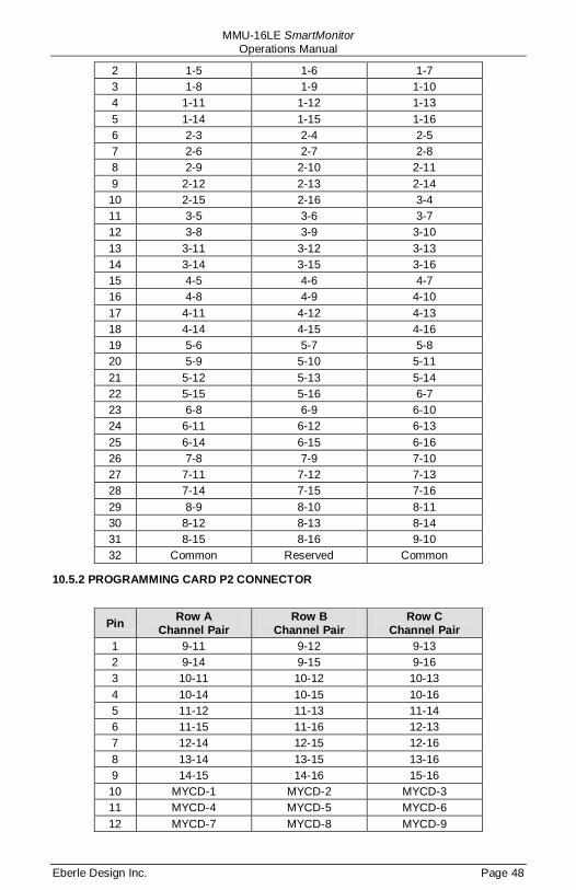
MMU-16LE SmartMonitor Operations Manual
Eberle Design Inc. Page 48
2 1-5 1-6 1-7 3 1-8 1-9 1-10 4 1-11 1-12 1-13 5 1-14 1-15 1-16 6 2-3 2-4 2-5 7 2-6 2-7 2-8 8 2-9 2-10 2-11 9 2-12 2-13 2-14 10 2-15 2-16 3-4 11 3-5 3-6 3-7 12 3-8 3-9 3-10 13 3-11 3-12 3-13 14 3-14 3-15 3-16 15 4-5 4-6 4-7 16 4-8 4-9 4-10 17 4-11 4-12 4-13 18 4-14 4-15 4-16 19 5-6 5-7 5-8 20 5-9 5-10 5-11 21 5-12 5-13 5-14 22 5-15 5-16 6-7 23 6-8 6-9 6-10 24 6-11 6-12 6-13 25 6-14 6-15 6-16 26 7-8 7-9 7-10 27 7-11 7-12 7-13 28 7-14 7-15 7-16 29 8-9 8-10 8-11 30 8-12 8-13 8-14 31 8-15 8-16 9-10 32 Common Reserved Common
10.5.2 PROGRAMMING CARD P2 CONNECTOR
Pin Row A Channel Pair
Row B Channel Pair
Row C Channel Pair
1 9-11 9-12 9-13 2 9-14 9-15 9-16 3 10-11 10-12 10-13 4 10-14 10-15 10-16 5 11-12 11-13 11-14 6 11-15 11-16 12-13 7 12-14 12-15 12-16 8 13-14 13-15 13-16 9 14-15 14-16 15-16 10 MYCD-1 MYCD-2 MYCD-3 11 MYCD-4 MYCD-5 MYCD-6 12 MYCD-7 MYCD-8 MYCD-9

MMU-16LE SmartMonitor Operations Manual
Eberle Design Inc. Page 49
13 MYCD-10 MYCD-11 MYCD-12 14 MYCD-13 MYCD-14 MYCD-15 15 MYCD-16 Reserved Reserved 16 Reserved Reserved Reserved 17 Reserved Reserved Reserved 18 Reserved Reserved Reserved 19 Reserved Reserved Reserved 20 Reserved Reserved Reserved 21 Minimum Flash b8 Minimum Flash b4 Minimum Flash b2 22 Minimum Flash b1 24V Latch Enable CVM Latch Enable 23 Reserved Reserved Reserved 24 Reserved Reserved Reserved 25 Reserved Reserved Reserved 26 Reserved Reserved Reserved 27 Reserved Reserved Reserved 28 Reserved Reserved Reserved 29 Reserved Reserved Reserved 30 Reserved Reserved Reserved 31 Reserved Reserved Reserved 32 Common Common Common
NOTE—MYCD-n refers to Minimum Yellow Change Disable input for channel n
10.6 PORT 1 CONNECTOR The Port 1 connector intermates with a 15 pin D type connector, AMP Incorporated part number 205206-1 or equivalent.
Pin Function 1 Rx Data + 2 Logic Ground 3 Rx Clock + 4 Logic Ground 5 Tx Data + 6 Logic Ground 7 Tx Clock + 8 Logic Ground 9 Rx Data-
10 Port 1 Disable (0 VDC = disable)
11 Rx Clock- 12 Earth Ground 13 Tx Data- 14 Reserved 15 Tx Clock-
10.7 EIA-232 CONNECTOR
Pin Function I/O 1 DCD O
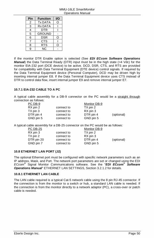
MMU-16LE SmartMonitor Operations Manual
Eberle Design Inc. Page 50
Pin Function I/O 2 Tx DATA O 3 Rx DATA I 4 DTR I 5 GROUND - 6 DSR O 7 CTS I 8 RTS O 9 NC -
If the monitor DTR Enable option is selected (See EDI ECcom Software Operations Manual) the Data Terminal Ready (DTR) input must be in the high state (>4 Vdc) for the monitor EIA-232 port (DCE device) to be active. DCD, DSR, CTS, and RTS are provided for compatibility with Data Terminal Equipment (DTE device) control signals. If required by the Data Terminal Equipment device (Personal Computer), DCD may be driven high by inserting internal jumper E8. If the Data Terminal Equipment device uses CTS instead of DTR to control data flow, insert internal jumper E9 and remove internal jumper E7.
10.7.1 EIA-232 CABLE TO A PC A typical cable assembly for a DB-9 connector on the PC would be a straight through
connection as follows:
PC DB-9 RX pin 2 connect to TX pin 2
Monitor DB-9
TX pin 3 connect to RX pin 3 DTR pin 4 connect to DTR pin 4 (optional) GND pin 5 connect to GND pin 5 A typical cable assembly for a DB-25 connector on the PC would be as follows: PC DB-25 RX pin 3 connect to TX pin 2
Monitor DB-9
TX pin 2 connect to RX pin 3 DTR pin 20 connect to DTR pin 4 (optional) GND pin 7 connect to GND pin 5
10.8 ETHERNET LAN PORT (J2)
The optional Ethernet port must be configured with specific network parameters such as an IP address, Mask, and Port. The network port parameters are set or changed using the EDI ECcom® Signal Monitor Communications software. See the "EDI ECcom® Software Operations Manual" ETHERNET LAN SETTINGS, Section 3.2.1.2 for details.
10.8.1 ETHERNET LAN CABLE
The LAN cable required is a typical Cat-5 network cable using the 8 pin RJ-45 connector. If the connection is from the monitor to a switch or hub, a standard LAN cable is needed. If the connection is from the monitor directly to a network adaptor (PC), a cross-over or patch cable is needed.


![MMU - Texas EMTFtxemtf.org/wp-content/uploads/2019/09/MMU-FINAL.pdf · MMU Tent Structure for 32+ Beds, 53’ MMU Command Trailer MMU Supply, Pharmacy, & Diagnostic Equipment [2]](https://img.dokumen.tips/doc/110x75/5eb70ed4759f960e1f5063e5/mmu-texas-mmu-tent-structure-for-32-beds-53a-mmu-command-trailer-mmu-supply.jpg)