Embed Size (px)
Citation preview
[email protected]@gmail.comMovil:959440045
A L F A L A V A L S E P A R A T I O N
MMPX 303SGP-11
Separator Manual
Product No. 881099-01-04
Book No. 1270065-02 V2
www.fdm.com.pe
[email protected]@gmail.comMovil:959440045
Alfa Laval Separation ABSeparator Manuals, dept. SKLS-147 80 Tumba, Sweden
Telephone: +46 8 53 06 50 00Telefax: +46 8 53 06 50 29
Printed in Sweden, 97-03
© Alfa Laval Separation AB 1997
This publication or any part thereof may not be reproduced or transmitted by any process or means without prior written permission of Alfa Laval Separation AB.
www.fdm.com.pe

[email protected]@gmail.comMovil:959440045
Contents
1 Read this first 7
2 Safety Instructions 9
3 Separator Basics 15
3.1 Basic principles of separation 16
3.2 Design and function 24
3.3 Definitions 32
4 Operating Instructions 33
4.1 Operating routine 34
5 Service Instructions 41
5.1 Periodic maintenance 42
5.2 Maintenance Logs 45
5.3 Check points at Intermediate Service 51
5.4 Check points at Major Service 63
5.5 3-year service 65
5.6 Lifting instructions 66
5.7 Cleaning 68
5.8 Oil change 71
5.9 Vibration 73
5.10 General directions 74
6 Dismantling/Assembly 79
6.1 Inlet/outlet and bowl 81
6.2 Bowl spindle and frame 99
6.3 Friction coupling 110
6.4 Flat belt and tightener 116
3
www.fdm.com.pe
ventafdmsaMovil:
6.5 Oil filling device 121
6.6 Water tank 122
6.7 Frame feet 123
7 Trouble-tracing 125
7.1 Trouble-tracing procedure 126
7.2 MMPX mechanical function 126
7.3 Purification and clarification faults 132
7.4 Purification faults 134
7.5 Clarification faults 136
8 Technical Reference 137
8.1 Technical data 138
8.2 Connection list 141
8.3 Interface description 143
8.4 Water quality 146
8.5 Lubricants 147
8.6 Drawings 156
8.7 Storage and installation 168
Index 179
[email protected]@gmail.com959440045
4
www.fdm.com.pe
[email protected]@gmaMovil:9594400
ls and observe the ion, operation, .
ions can result in
clear only foreseeable conditions ings are given, therefore, for
ended usage of the machine and its
Study instruction manuawarnings before installatservice and maintenance
Not following the instructserious accidents.
In order to make the informationhave been considered. No warnsituations arising from the uninttools.
om.peil.com45
5
www.fdm.com.pe
[email protected]@gmaMovil:9594400
1 Read this first
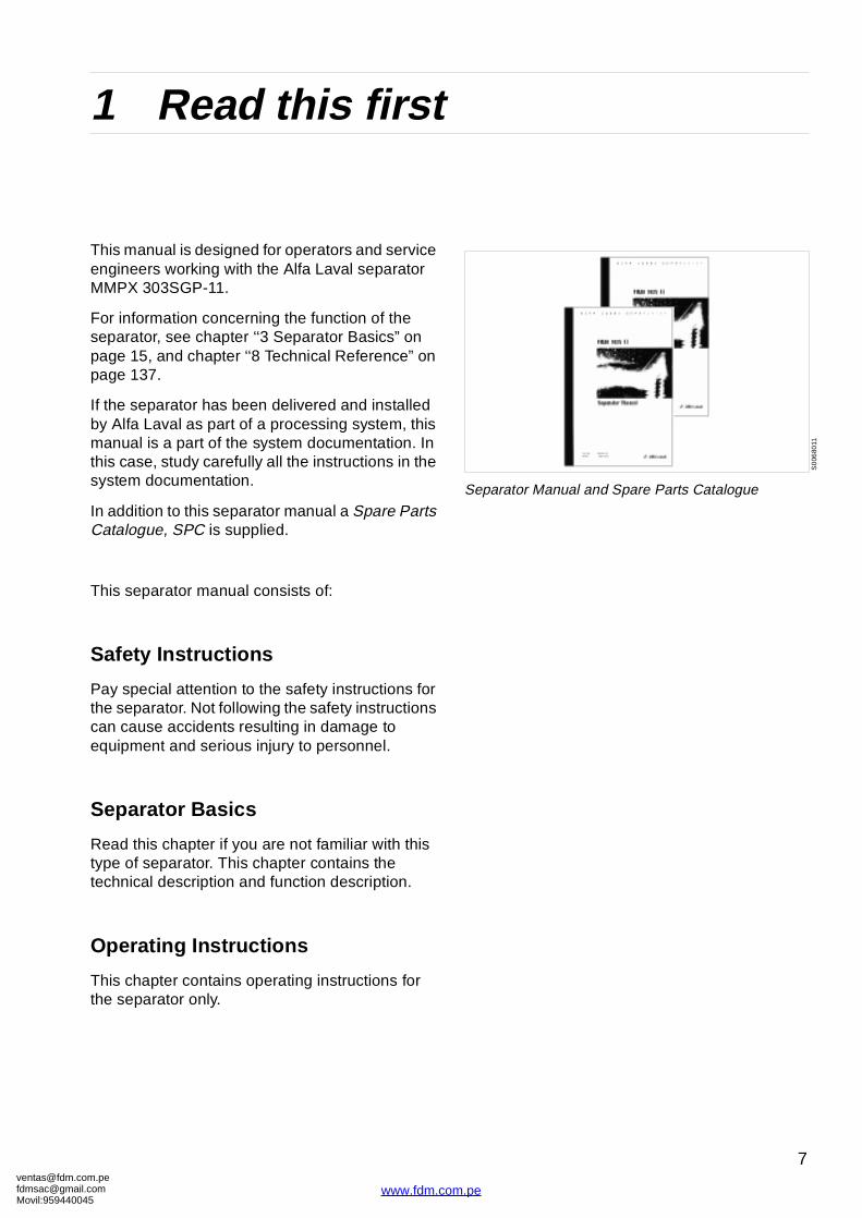
This manual is designed for operators and service engineers working with the Alfa Laval separator MMPX 303SGP-11.
For information concerning the function of the separator, see chapter ‘‘3 Separator Basics” on page 15, and chapter ‘‘8 Technical Reference” on page 137.
If the separator has been delivered and installed by Alfa Laval as part of a processing system, this manual is a part of the system documentation. In this case, study carefully all the instructions in the system documentation.
In addition to this separator manual a Spare Parts Catalogue, SPC is supplied.
This separator manual consists of:
Safety Instructions
Pay special attention to the safety instructions for the separator. Not following the safety instructions can cause accidents resulting in damage to equipment and serious injury to personnel.
Separator Basics
Read this chapter if you are not familiar with this type of separator. This chapter contains the technical description and function description.
Operating Instructions
This chapter contains operating instructions for the separator only.
om.peil.com45
www.fdm.co
S0
0680
11
Separator Manual and Spare Parts Catalogue
7
m.pe

ventafdmsaMovil:
1 Read this first
Service Instructions
This chapter gives instructions for daily checks, cleaning, oil changes, servicing and check points.
Dismantling / Assembly
This chapter contains step-by-step instructions for dismantling and assembly of the separator for service and repair.
Trouble-tracing
Refer to this chapter if the separator functions abnormally.
If the separator has been installed as part of a processing system always refer to the trouble-tracing part of the system documentation first.
Technical Reference
This chapter contains technical data and drawings concerning the separator.
Index
This chapter contains an alphabetical list of subjects, with page references.
[email protected]@gmail.com959440045
8
www.fdm.com.pe
[email protected]@gmaMovil:9594400
2 Safety Instructions
G00
1041
1
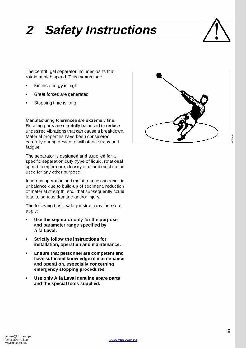
The centrifugal separator includes parts that rotate at high speed. This means that:
• Kinetic energy is high
• Great forces are generated
• Stopping time is long
Manufacturing tolerances are extremely fine. Rotating parts are carefully balanced to reduce undesired vibrations that can cause a breakdown. Material properties have been considered carefully during design to withstand stress and fatigue.
The separator is designed and supplied for a specific separation duty (type of liquid, rotational speed, temperature, density etc.) and must not be used for any other purpose.
Incorrect operation and maintenance can result in unbalance due to build-up of sediment, reduction of material strength, etc., that subsequently could lead to serious damage and/or injury.
The following basic safety instructions therefore apply:
• Use the separator only for the purpose and parameter range specified by Alfa Laval.
• Strictly follow the instructions for installation, operation and maintenance.
• Ensure that personnel are competent and have sufficient knowledge of maintenance and operation, especially concerning emergency stopping procedures.
• Use only Alfa Laval genuine spare parts and the special tools supplied.
om.peil.com45
9
www.fdm.com.pe
ventafdmsaMovil:
2 Safety Instructions
S00
513
11S
005
5611
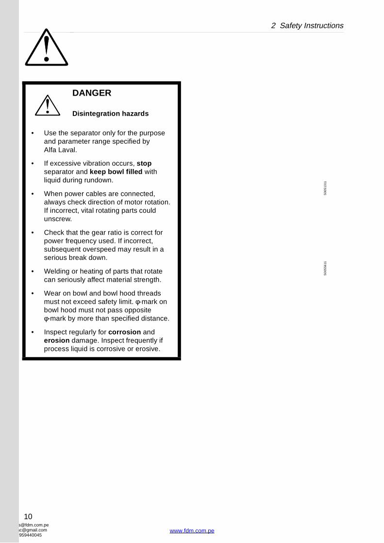
DANGER
Disintegration hazards
• Use the separator only for the purpose and parameter range specified by Alfa Laval.
• If excessive vibration occurs, stop separator and keep bowl filled with liquid during rundown.
• When power cables are connected, always check direction of motor rotation. If incorrect, vital rotating parts could unscrew.
• Check that the gear ratio is correct for power frequency used. If incorrect, subsequent overspeed may result in a serious break down.
• Welding or heating of parts that rotate can seriously affect material strength.
• Wear on bowl and bowl hood threads must not exceed safety limit. φ-mark on bowl hood must not pass opposite φ-mark by more than specified distance.
• Inspect regularly for corrosion and erosion damage. Inspect frequently if process liquid is corrosive or erosive.
[email protected]@gmail.com959440045
10
www.fdm.com.pe
[email protected]@gmaMovil:9594400
2 Safety Instructions
S0
0511
11S
005
1011
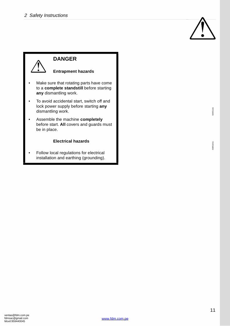
DANGER
Entrapment hazards
• Make sure that rotating parts have come to a complete standstill before starting any dismantling work.
• To avoid accidental start, switch off and lock power supply before starting any dismantling work.
• Assemble the machine completely before start. All covers and guards must be in place.
Electrical hazards
• Follow local regulations for electrical installation and earthing (grounding).
om.peil.com45
11
www.fdm.com.pe
ventafdmsaMovil:
2 Safety Instructions
S0
051
711
S0
051
611
S0
055
411
S00
543
11
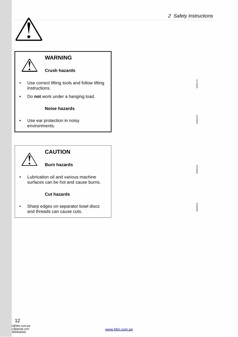
WARNING
Crush hazards
• Use correct lifting tools and follow lifting instructions.
• Do not work under a hanging load.
Noise hazards
• Use ear protection in noisy environments.
CAUTION
Burn hazards
• Lubrication oil and various machine surfaces can be hot and cause burns.
Cut hazards
• Sharp edges on separator bowl discs and threads can cause cuts.
[email protected]@gmail.com959440045
12
www.fdm.com.pe

[email protected]@gmaMovil:9594400
2 Safety Instructions
Warning signs in the text
Pay attention to the safety instructions in this manual. Below are definitions of the three grades of warning signs used in the text where there is a risk for injury to personnel.
DANGER
Type of hazard
This type of safety instruction indicates a situation which, if not avoided, could result in fatal injury or fatal damage to health.
WARNING
Type of hazard
This type of safety instruction indicates a situation which, if not avoided, could result in disabling injury or disabling damage to health.
CAUTION
Type of hazard
This type of safety instruction indicates a situation which, if not avoided, could result in light injury or light damage to health.
NOTE
This type of instruction indicates a situation which, if not avoided, could result in damage to the equipment.
om.peil.com45
13
www.fdm.com.pe
[email protected]@gmaMovil:9594400
3 Separator Basics
Contents
3.1 Basic principles of separation 16
3.1.1 Factors influencing the separation result 17
3.1.2 Purification 20
3.1.3 Clarification (optional) 22
3.2 Design and function 24
3.2.1 Application 24
3.2.2 Design 25
3.2.3 Outline of function 25
3.2.4 Separating function 26
3.2.5 Sludge discharge function 28
3.2.6 Power transmission 30
3.2.7 Sensors and indicators 31
3.3 Definitions 32
om.peil.com45
www.fdm.co
15
m.pe
ventafdmsaMovil:
3.1 Basic principles of separation 3 Separator Basics
G00
107
11
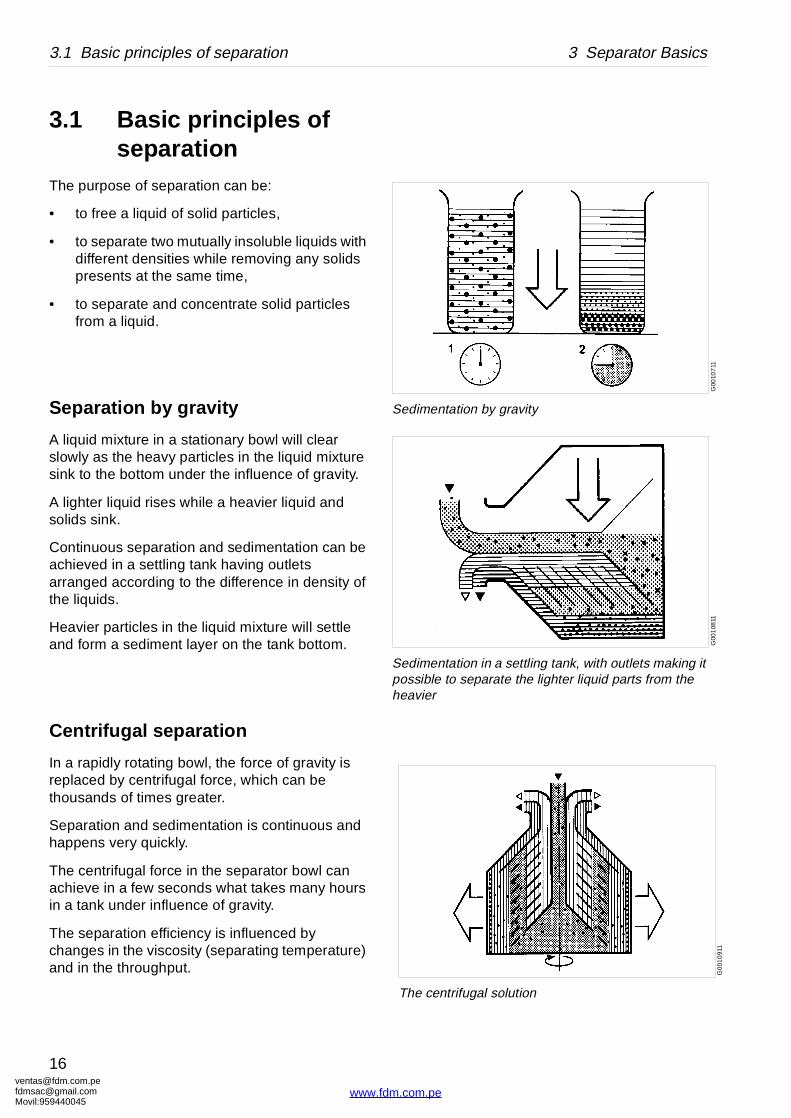
Sedimentation by gravity
G00
108
11
Sedimentation in a settling tank, with outlets making it possible to separate the lighter liquid parts from the heavier
G0
010
911
The centrifugal solution
3.1 Basic principles of separation
The purpose of separation can be:
• to free a liquid of solid particles,
• to separate two mutually insoluble liquids with different densities while removing any solids presents at the same time,
• to separate and concentrate solid particles from a liquid.
Separation by gravity
A liquid mixture in a stationary bowl will clear slowly as the heavy particles in the liquid mixture sink to the bottom under the influence of gravity.
A lighter liquid rises while a heavier liquid and solids sink.
Continuous separation and sedimentation can be achieved in a settling tank having outlets arranged according to the difference in density of the liquids.
Heavier particles in the liquid mixture will settle and form a sediment layer on the tank bottom.
Centrifugal separation
In a rapidly rotating bowl, the force of gravity is replaced by centrifugal force, which can be thousands of times greater.
Separation and sedimentation is continuous and happens very quickly.
The centrifugal force in the separator bowl can achieve in a few seconds what takes many hours in a tank under influence of gravity.
The separation efficiency is influenced by changes in the viscosity (separating temperature) and in the throughput.
[email protected]@gmail.com959440045
16
www.fdm.com.pe
[email protected]@gmaMovil:9594400
3 Separator Basics 3.1 Basic principles of separation
G0
011
011
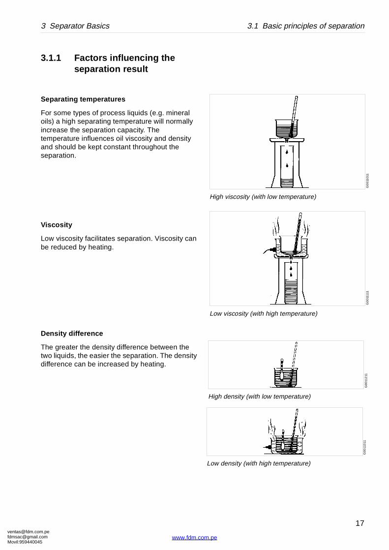
High viscosity (with low temperature)
G0
011
111
Low viscosity (with high temperature)
G00
112
11
High density (with low temperature)
G00
113
11
Low density (with high temperature)
3.1.1 Factors influencing the separation result
Separating temperatures
For some types of process liquids (e.g. mineral oils) a high separating temperature will normally increase the separation capacity. The temperature influences oil viscosity and density and should be kept constant throughout the separation.
Viscosity
Low viscosity facilitates separation. Viscosity can be reduced by heating.
Density difference
The greater the density difference between the two liquids, the easier the separation. The density difference can be increased by heating.
om.peil.com45
17
www.fdm.com.pe
ventafdmsaMovil:
3.1 Basic principles of separation 3 Separator Basics
2 1
A
B
m³/h
µm
G0
6133
11
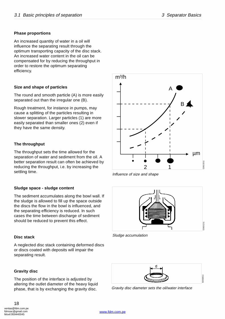
Influence of size and shape
G0
6012
11
Sludge accumulation
S0
068
611
Gravity disc diameter sets the oil/water interface
Phase proportions
An increased quantity of water in a oil will influence the separating result through the optimum transporting capacity of the disc stack. An increased water content in the oil can be compensated for by reducing the throughput in order to restore the optimum separating efficiency.
Size and shape of particles
The round and smooth particle (A) is more easily separated out than the irregular one (B).
Rough treatment, for instance in pumps, may cause a splitting of the particles resulting in slower separation. Larger particles (1) are more easily separated than smaller ones (2) even if they have the same density.
The throughput
The throughput sets the time allowed for the separation of water and sediment from the oil. A better separation result can often be achieved by reducing the throughput, i.e. by increasing the settling time.
Sludge space - sludge content
The sediment accumulates along the bowl wall. If the sludge is allowed to fill up the space outside the discs the flow in the bowl is influenced, and the separating efficiency is reduced. In such cases the time between discharge of sediment should be reduced to prevent this effect.
Disc stack
A neglected disc stack containing deformed discs or discs coated with deposits will impair the separating result.
Gravity disc
The position of the interface is adjusted by altering the outlet diameter of the heavy liquid phase, that is by exchanging the gravity disc.
[email protected]@gmail.com959440045
18
www.fdm.com.pe

[email protected]@gmaMovil:9594400
3 Separator Basics 3.1 Basic principles of separation
om.peil.com45
19
www.fdm.com.pe
ventafdmsaMovil:
3.1 Basic principles of separation 3 Separator Basics
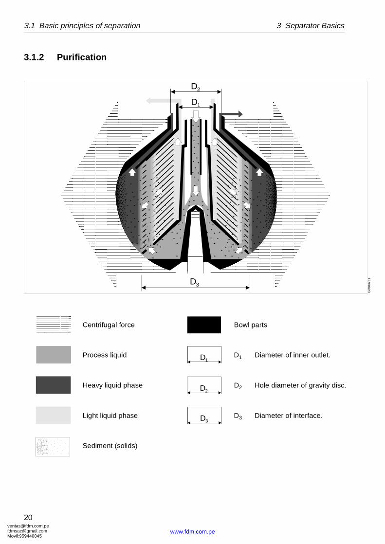
Bowl parts
D1 Diameter of inner outlet.
D2 Hole diameter of gravity disc.
D3 Diameter of interface.
D1
D2
D3
G0
5037
31
D1
D2
D3
3.1.2 Purification
Centrifugal force
Process liquid
Heavy liquid phase
Light liquid phase
Sediment (solids)
[email protected]@gmail.com959440045
20
www.fdm.com.pe
[email protected]@gmaMovil:9594400
3 Separator Basics 3.1 Basic principles of separation
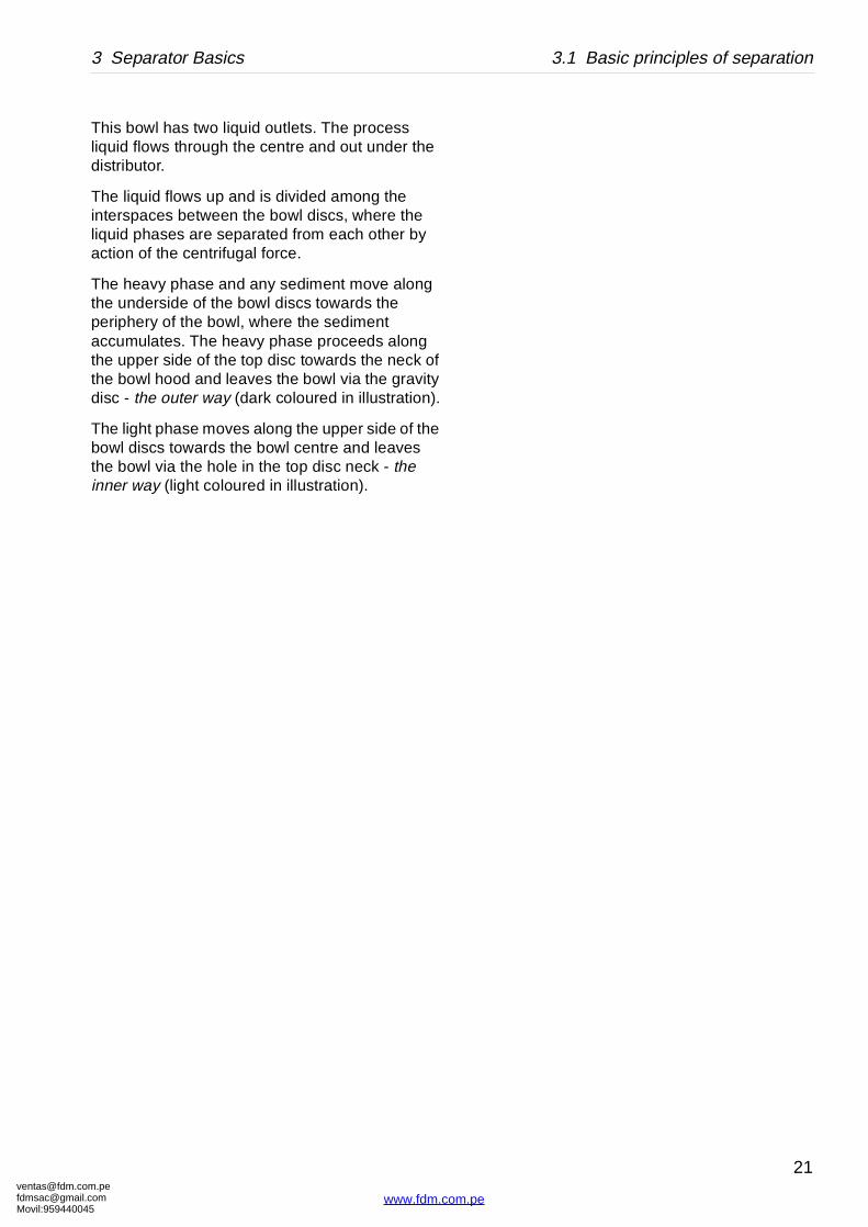
This bowl has two liquid outlets. The process liquid flows through the centre and out under the distributor.
The liquid flows up and is divided among the interspaces between the bowl discs, where the liquid phases are separated from each other by action of the centrifugal force.
The heavy phase and any sediment move along the underside of the bowl discs towards the periphery of the bowl, where the sediment accumulates. The heavy phase proceeds along the upper side of the top disc towards the neck of the bowl hood and leaves the bowl via the gravity disc - the outer way (dark coloured in illustration).
The light phase moves along the upper side of the bowl discs towards the bowl centre and leaves the bowl via the hole in the top disc neck - the inner way (light coloured in illustration).
om.peil.com45
21
www.fdm.com.pe
ventafdmsaMovil:
3.1 Basic principles of separation 3 Separator Basics
G0
5037
11
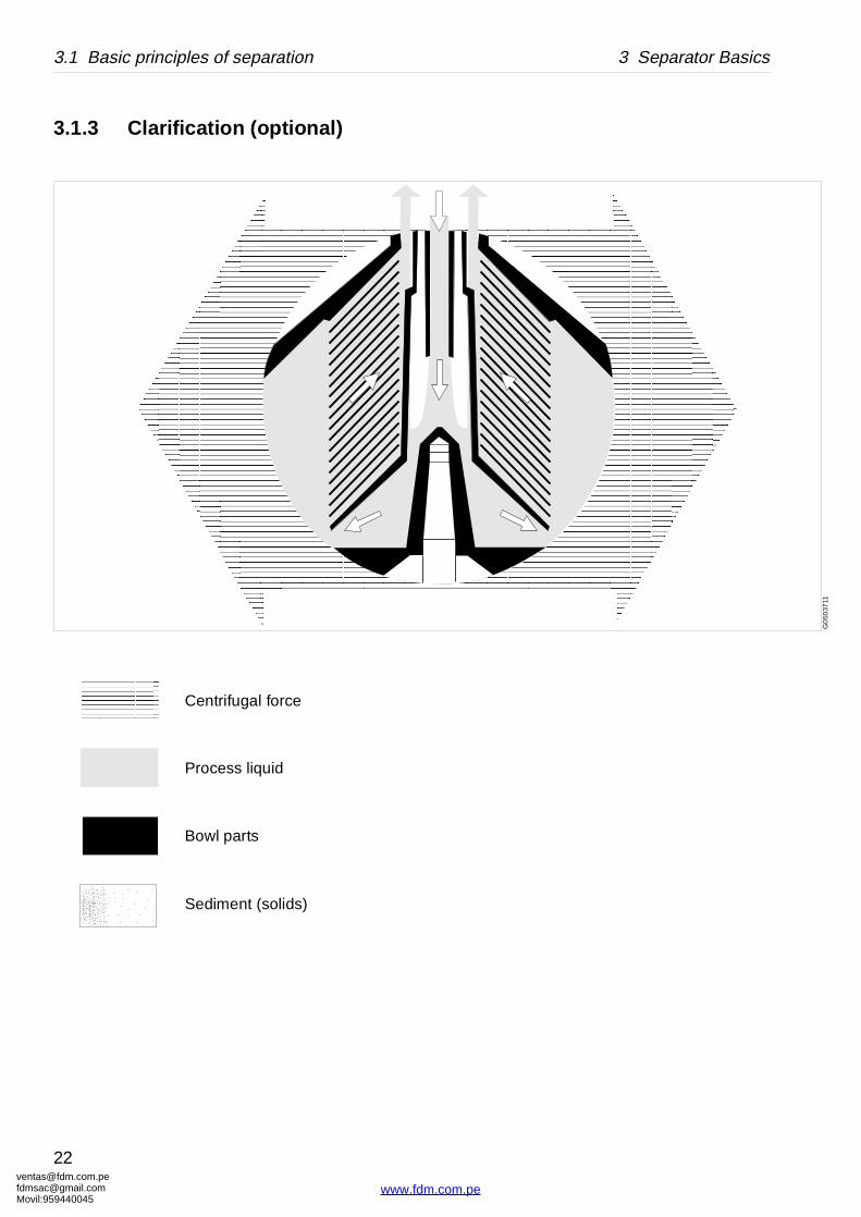
3.1.3 Clarification (optional)
Centrifugal force
Process liquid
Bowl parts
Sediment (solids)
[email protected]@gmail.com959440045
22
www.fdm.com.pe
[email protected]@gmaMovil:9594400
3 Separator Basics 3.1 Basic principles of separation
This bowl has one liquid outlet.
The process liquid flows through the centre of the distributor.
The liquid flows up and is divided among the interspaces between the bowl discs, where the sediment is separated from the liquid by action of the centrifugal force.
The sediment moves along the underside of the bowl discs towards the periphery of the bowl, where it accumulates.
om.peil.com45
23
www.fdm.com.pe
ventafdmsaMovil:
3.2 Design and function 3 Separator Basics
G0
358
311
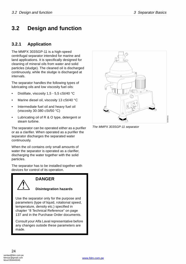
The MMPX 303SGP-11 separator
3.2 Design and function
3.2.1 Application
The MMPX 303SGP-11 is a high-speed centrifugal separator intended for marine and land applications. It is specifically designed for cleaning of mineral oils from water and solid particles (sludge). The cleaned oil is discharged continuously, while the sludge is discharged at intervals.
The separator handles the following types of lubricating oils and low viscosity fuel oils:
• Distillate, viscosity 1,5 - 5,5 cSt/40 °C
• Marine diesel oil, viscosity 13 cSt/40 °C
• Intermediate fuel oil and heavy fuel oil (viscosity 30-380 cSt/50 °C)
• Lubricating oil of R & O type, detergent or steam turbine.
The separator can be operated either as a purifier or as a clarifier. When operated as a purifier the separator discharges the separated water continuously.
When the oil contains only small amounts of water the separator is operated as a clarifier, discharging the water together with the solid particles.
The separator has to be installed together with devices for control of its operation.
DANGER
Disintegration hazards
Use the separator only for the purpose and parameters (type of liquid, rotational speed, temperature, density etc.) specified in chapter ‘‘8 Technical Reference” on page 137 and in the Purchase Order documents.
Consult your Alfa Laval representative before any changes outside these parameters are made.
[email protected]@gmail.com959440045
24
www.fdm.com.pe
[email protected]@gmaMovil:9594400
3 Separator Basics 3.2 Design and function
G0
1121
31
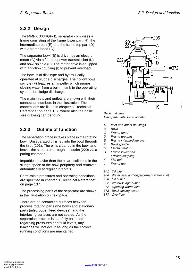
Sectional viewMain parts, inlets and outlets
A Inlet and outlet housingsB BowlC Frame hoodD Frame top partE Frame intermediate partF Bowl spindleG Electric motorH Frame lower partI Friction couplingK Flat beltL Frame feet
201 Oil inlet206 Water seal and displacement water inlet220 Oil outlet222 Water/sludge outlet372 Opening water inlet373 Bowl closing water377 Overflow
3.2.2 Design
The MMPX 303SGP-11 separator comprises a frame consisting of the frame lower part (H), the intermediate part (E) and the frame top part (D) with a frame hood (C).
The separator bowl (B) is driven by an electric motor (G) via a flat-belt power transmission (K) and bowl spindle (F). The motor drive is equipped with a friction coupling (I) to prevent overload.
The bowl is of disc type and hydraulically operated at sludge discharges. The hollow bowl spindle (F) features an impeller which pumps closing water from a built-in tank to the operating system for sludge discharge.
The main inlets and outlets are shown with their connection numbers in the illustration. The connections are listed in chapter ‘‘8 Technical Reference” on page 137, where also the basic size drawing can be found.
3.2.3 Outline of function
The separation process takes place in the rotating bowl. Unseparated oil is fed into the bowl through the inlet (201). The oil is cleaned in the bowl and leaves the separator through the outlet (220) via a paring chamber.
Impurities heavier than the oil are collected in the sludge space at the bowl periphery and removed automatically at regular intervals.
Permissible pressures and operating conditions are specified in chapter ‘‘8 Technical Reference” on page 137.
The processing parts of the separator are shown in the illustration on next page.
There are no contacting surfaces between process rotating parts (the bowl) and stationary parts (inlet, outlet, feed devices), and the interfacing surfaces are not sealed. As the separation process is carefully balanced regarding pressures and fluid levels, any leakages will not occur as long as the correct running conditions are maintained.
om.peil.com45
25
www.fdm.com.pe

ventafdmsaMovil:
3.2 Design and function 3 Separator Basics
G01
123
31F Paring discG Disc stackH Sludge spaceI Top discK Gravity discL Sludge portsR Bowl bodyS Bowl hoodT DistributorU Paring chamber
coverV Guiding coneW Heavy phase cover
201 Oil inlet206 Water seal and
displacement water inlet
220 Oil outlet221 Water/sludge outlet372 Opening water inlet373 Bowl closing water377 Overflow
3.2.4 Separating function
Liquid flow
Separation takes place in the separator bowl to which unseparated oil is fed through the inlet pipe (201). The oil is led by the distributor (T) towards the periphery of the bowl.
When the unseparated oil reaches the slots of the distributor, it will rise through the channels formed by the disc stack (G) where it is evenly distributed into the disc stack.
The oil is continuously separated from water and sludge as it will flow towards the center of the bowl. When the cleaned oil leaves the disc stack it rises upwards and enters the paring chamber. From there it is pumped by the paring disc (F) and leaves the bowl through the outlet (220).
Separated sludge and water move towards the bowl periphery. In purification separated water rises along the outside of the disc stack, passes from the top disc channels over the gravity disc (K) and leaves the bowl through a small hole in the heavy phase cover (W) into the common sludge and water outlet (221) of the separator.
Heavier impurities are collected in the sludge space (H) outside the disc stack and are discharged at intervals through the sludge ports (L).
[email protected]@gmail.com959440045
26
www.fdm.com.pe
[email protected]@gmaMovil:9594400
3 Separator Basics 3.2 Design and function
G01
126
21
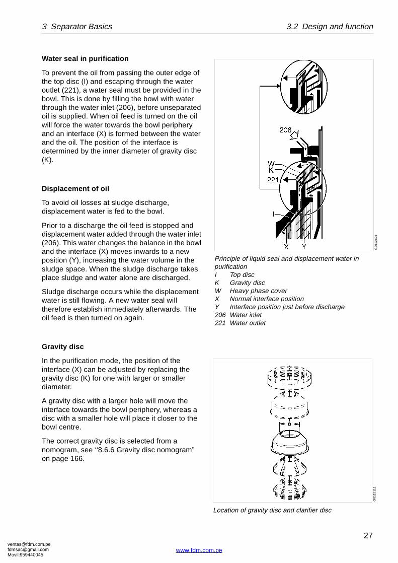
Principle of liquid seal and displacement water in purificationI Top discK Gravity discW Heavy phase coverX Normal interface positionY Interface position just before discharge206 Water inlet221 Water outlet
G01
1511
1
Location of gravity disc and clarifier disc
Water seal in purification
To prevent the oil from passing the outer edge of the top disc (I) and escaping through the water outlet (221), a water seal must be provided in the bowl. This is done by filling the bowl with water through the water inlet (206), before unseparated oil is supplied. When oil feed is turned on the oil will force the water towards the bowl periphery and an interface (X) is formed between the water and the oil. The position of the interface is determined by the inner diameter of gravity disc (K).
Displacement of oil
To avoid oil losses at sludge discharge, displacement water is fed to the bowl.
Prior to a discharge the oil feed is stopped and displacement water added through the water inlet (206). This water changes the balance in the bowl and the interface (X) moves inwards to a new position (Y), increasing the water volume in the sludge space. When the sludge discharge takes place sludge and water alone are discharged.
Sludge discharge occurs while the displacement water is still flowing. A new water seal will therefore establish immediately afterwards. The oil feed is then turned on again.
Gravity disc
In the purification mode, the position of the interface (X) can be adjusted by replacing the gravity disc (K) for one with larger or smaller diameter.
A gravity disc with a larger hole will move the interface towards the bowl periphery, whereas a disc with a smaller hole will place it closer to the bowl centre.
The correct gravity disc is selected from a nomogram, see ‘‘8.6.6 Gravity disc nomogram” on page 166.
om.peil.com45
27
www.fdm.com.pe
ventafdmsaMovil:
3.2 Design and function 3 Separator Basics
G01
124
11
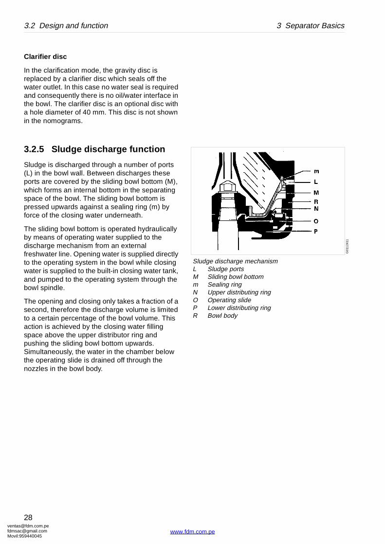
Sludge discharge mechanismL Sludge portsM Sliding bowl bottomm Sealing ringN Upper distributing ringO Operating slideP Lower distributing ringR Bowl body
Clarifier disc
In the clarification mode, the gravity disc is replaced by a clarifier disc which seals off the water outlet. In this case no water seal is required and consequently there is no oil/water interface in the bowl. The clarifier disc is an optional disc with a hole diameter of 40 mm. This disc is not shown in the nomograms.
3.2.5 Sludge discharge function
Sludge is discharged through a number of ports (L) in the bowl wall. Between discharges these ports are covered by the sliding bowl bottom (M), which forms an internal bottom in the separating space of the bowl. The sliding bowl bottom is pressed upwards against a sealing ring (m) by force of the closing water underneath.
The sliding bowl bottom is operated hydraulically by means of operating water supplied to the discharge mechanism from an external freshwater line. Opening water is supplied directly to the operating system in the bowl while closing water is supplied to the built-in closing water tank, and pumped to the operating system through the bowl spindle.
The opening and closing only takes a fraction of a second, therefore the discharge volume is limited to a certain percentage of the bowl volume. This action is achieved by the closing water filling space above the upper distributor ring and pushing the sliding bowl bottom upwards. Simultaneously, the water in the chamber below the operating slide is drained off through the nozzles in the bowl body.
[email protected]@gmail.com959440045
28
www.fdm.com.pe
[email protected]@gmaMovil:9594400
3 Separator Basics 3.2 Design and function
G01
125
21
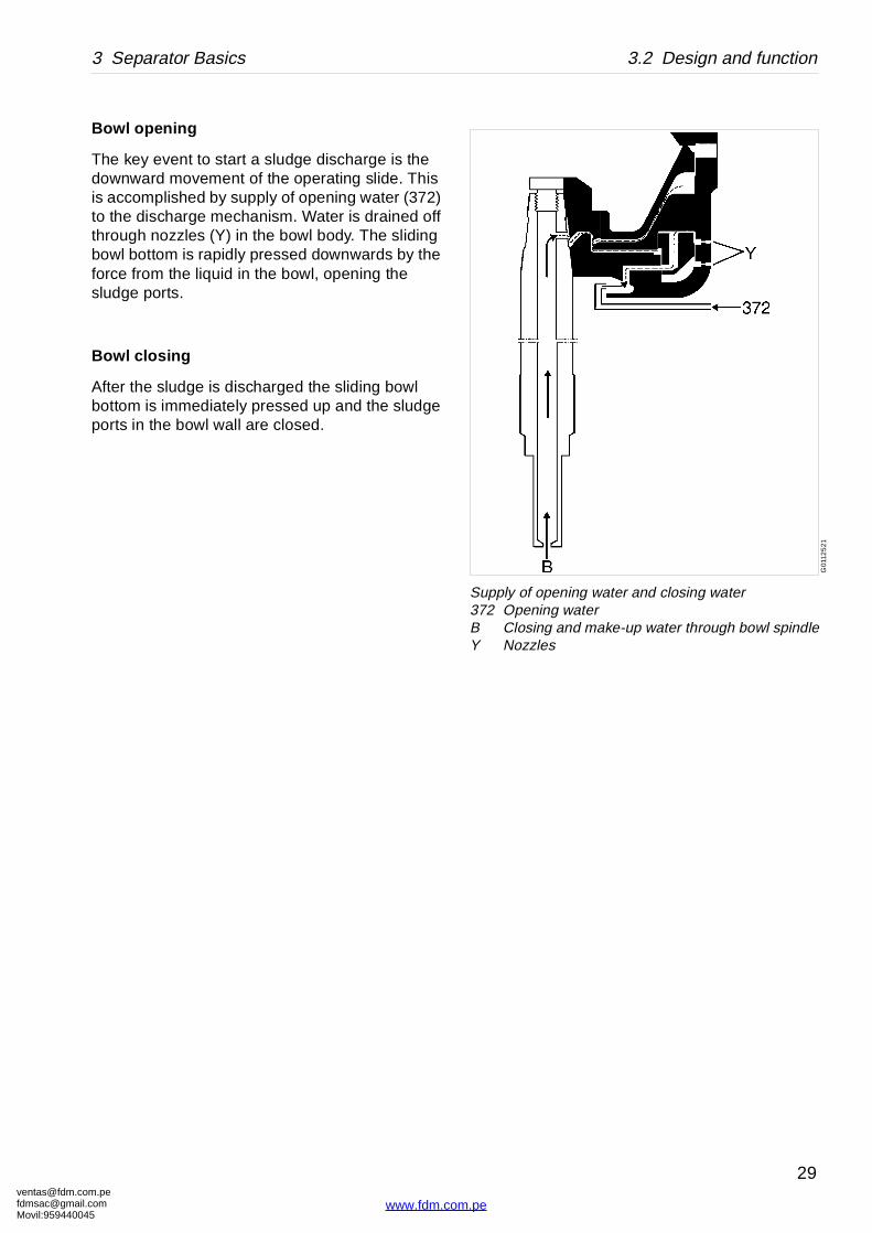
Supply of opening water and closing water372 Opening waterB Closing and make-up water through bowl spindleY Nozzles
Bowl opening
The key event to start a sludge discharge is the downward movement of the operating slide. This is accomplished by supply of opening water (372) to the discharge mechanism. Water is drained off through nozzles (Y) in the bowl body. The sliding bowl bottom is rapidly pressed downwards by the force from the liquid in the bowl, opening the sludge ports.
Bowl closing
After the sludge is discharged the sliding bowl bottom is immediately pressed up and the sludge ports in the bowl wall are closed.
om.peil.com45
29
www.fdm.com.pe
ventafdmsaMovil:
3.2 Design and function 3 Separator Basics
G01
127
21
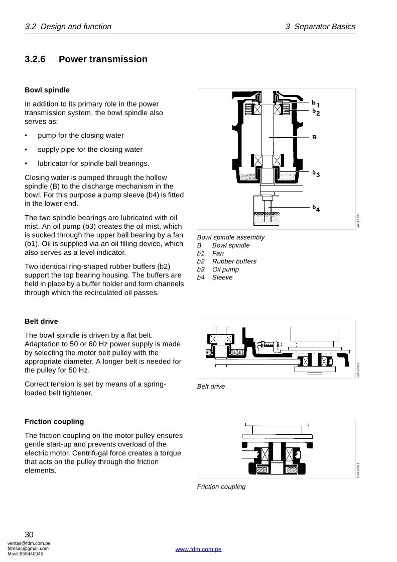
Bowl spindle assembly B Bowl spindleb1 Fanb2 Rubber buffersb3 Oil pumpb4 Sleeve
G0
112
821
Belt drive
G0
112
911
Friction coupling
3.2.6 Power transmission
Bowl spindle
In addition to its primary role in the power transmission system, the bowl spindle also serves as:
• pump for the closing water
• supply pipe for the closing water
• lubricator for spindle ball bearings.
Closing water is pumped through the hollow spindle (B) to the discharge mechanism in the bowl. For this purpose a pump sleeve (b4) is fitted in the lower end.
The two spindle bearings are lubricated with oil mist. An oil pump (b3) creates the oil mist, which is sucked through the upper ball bearing by a fan (b1). Oil is supplied via an oil filling device, which also serves as a level indicator.
Two identical ring-shaped rubber buffers (b2) support the top bearing housing. The buffers are held in place by a buffer holder and form channels through which the recirculated oil passes.
Belt drive
The bowl spindle is driven by a flat belt. Adaptation to 50 or 60 Hz power supply is made by selecting the motor belt pulley with the appropriate diameter. A longer belt is needed for the pulley for 50 Hz.
Correct tension is set by means of a spring-loaded belt tightener.
Friction c oupling
The friction coupling on the motor pulley ensures gentle start-up and prevents overload of the electric motor. Centrifugal force creates a torque that acts on the pulley through the friction elements.
[email protected]@gmail.com959440045
30
www.fdm.com.pe
[email protected]@gmaMovil:9594400
3 Separator Basics 3.2 Design and function
3.2.7 Sensors and indicators
Sight glass
The sight glass shows the oil level in the oil sump.
om.peil.com45
31
www.fdm.com.pe
ventafdmsaMovil:
3.3 Definitions 3 Separator Basics
tlet.
the intention of separating particles, normally lower density than the particles.
ces the gravity disc in the separator bowl, in the e disc seals off the heavy phase outlet in the ts.
ssed in kg/m3 at a specified temperature,
itioning the interface between the disc stack and c. This disc is only used in purifier mode.
heavy phase (water) and the light phase (oil) in a
nd inlet/outlet. Renewal of seals in bowl and inlet/
parator, including bottom part (and activities ervice). Renewal of seals and bearings in bottom
separated, e.g. oil.uid separated, e.g. water.
n with the intention of separating two intermixed phases of different densities. Solids having a s can be removed at the same time. The lighter jor part of the mixture, shall be purified as far as
d.
eparator bowl.
the separator per time unit.s/hour.
ement. Normally expressed in centistoke temperature.
the separator bowl to prevent the light phase (oil) h the heavy phase (water) outlet, in purifier mode.
3.3 DefinitionsBack pressure Pressure in the separator ou
Clarification Liquid/solids separation withsolids, from a liquid having a
Clarifier disc An optional disc, which replacase of clarifier operation. Thbowl, thus no liquid seal exis
Counter pressure See Back pressure.
Density Mass per volume unit. Exprenormally at 15 °C.
Gravity disc Disc in the bowl hood for posthe outer edge of the top dis
Interface Boundary layer between theseparator bowl.
Intermediate Service (IS)
Overhaul of separator bowl aoutlet.
Major Service (MS) Overhaul of the complete seincluded in an Intermediate Spart.
Phase Light phase: the lighter liquidHeavy phase: the heavier liq
Purification Liquid/liquid/solids separatioand mutually insoluble liquidhigher density than the liquidliquid phase, which is the mapossible.
Sediment (sludge) Solids separated from a liqui
Sludge discharge Ejection of sludge from the s
Throughput The feed of process liquid toExpressed in m3/hour or litre
Viscosity Fluid resistance against mov(cSt = mm2/s), at a specified
Water seal Water in the solids space of from leaving the bowl throug
[email protected]@gmail.com959440045
32
www.fdm.com.pe
[email protected]@gmaMovil:9594400
4 Operating Instructions
Contents
4.1 Operating routine 34
4.1.1 Before first start 34
4.1.2 Selection of gravity disc 34
4.1.3 Start after a service 35
4.1.4 Before normal start 35
4.1.5 Starting and running-up procedure 37
4.1.6 Separation 38
4.1.7 Stopping procedure 39
4.1.8 Safety stop 40
om.peil.com45
www.fdm.co
33
m.pe

ventafdmsaMovil:
4.1 Operating routine 4 Operating Instructions
G01
151
11
Location of gravity disc and clarifier disc
4.1 Operating routineThese operating instructions describe routine procedures to follow before and during the start, running and stopping sequences of the separator.
If system documentation is available always follow the operating instructions of this. If there is no system documentation the instructions below are to be followed.
4.1.1 Before first start
Technical demands for connections and logical limitations for the separator are listed in chapter ‘‘8 Technical Reference” on page 137:
• Technical data
• Connection list
• Interface description
• Basic size drawing
• Foundation drawing.
Before first start the following shall be checked:
1. Ensure the machine is installed correctly and that feed lines and drains have been flushed clean.
2. Fill oil in the oil sump. Fill up to the middle of the sight glass. For grade and quality of oil see ‘‘8.5.4 Recommended lubricating oils” on page 152.
4.1.2 Selection of gravity disc
The separator is delivered with a set of gravity discs with different diameters for purification operation. The hole diameter of the gravity disc sets the position of the oil/water interface in the separator, see page 27. The separation efficiency can be optimized by selection of the correct diameter for each oil quality.
As a guide the ‘‘8.6.6 Gravity disc nomogram” on page 166 can be used. The hole diameter of the first gravity disc to be tried can be read directly from the nomogram.
[email protected]@gmail.com959440045
34
www.fdm.com.pe
[email protected]@gmaMovil:9594400
4 Operating Instructions 4.1 Operating routine
G0
2840
41
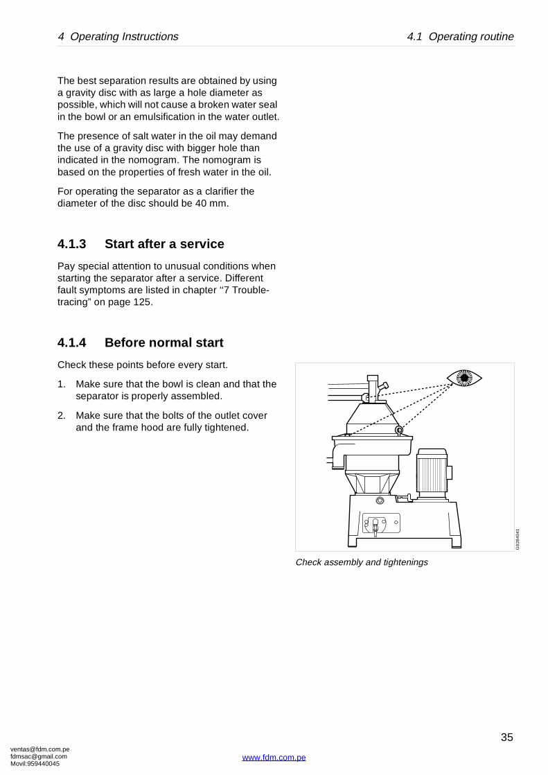
Check assembly and tightenings
The best separation results are obtained by using a gravity disc with as large a hole diameter as possible, which will not cause a broken water seal in the bowl or an emulsification in the water outlet.
The presence of salt water in the oil may demand the use of a gravity disc with bigger hole than indicated in the nomogram. The nomogram is based on the properties of fresh water in the oil.
For operating the separator as a clarifier the diameter of the disc should be 40 mm.
4.1.3 Start after a service
Pay special attention to unusual conditions when starting the separator after a service. Different fault symptoms are listed in chapter ‘‘7 Trouble-tracing” on page 125.
4.1.4 Before normal start
Check these points before every start.
1. Make sure that the bowl is clean and that the separator is properly assembled.
2. Make sure that the bolts of the outlet cover and the frame hood are fully tightened.
om.peil.com45
35
www.fdm.com.pe
ventafdmsaMovil:
4.1 Operating routine 4 Operating Instructions
S0
009
821
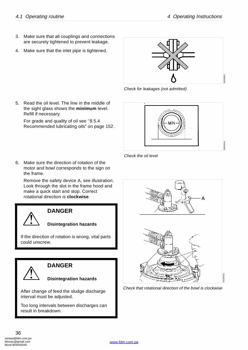
Check for leakages (not admitted)
S00
094
11
Check the oil level
G0
166
531
Check that rotational direction of the bowl is clockwise
3. Make sure that all couplings and connections are securely tightened to prevent leakage.
4. Make sure that the inlet pipe is tightened.
5. Read the oil level. The line in the middle of the sight glass shows the minimum level. Refill if necessary.
For grade and quality of oil see ‘‘8.5.4 Recommended lubricating oils” on page 152.
6. Make sure the direction of rotation of the motor and bowl corresponds to the sign on the frame.
Remove the safety device A, see illustration. Look through the slot in the frame hood and make a quick start and stop. Correct rotational direction is clockwise .
DANGER
Disintegration hazards
If the direction of rotation is wrong, vital parts could unscrew.
DANGER
Disintegration hazards
After change of feed the sludge discharge interval must be adjusted.
Too long intervals between discharges can result in breakdown.
[email protected]@gmail.com959440045
36
www.fdm.com.pe
[email protected]@gmaMovil:9594400
4 Operating Instructions 4.1 Operating routine
0
1
2
34 5 6
7
8
9
10
S0
0091
21
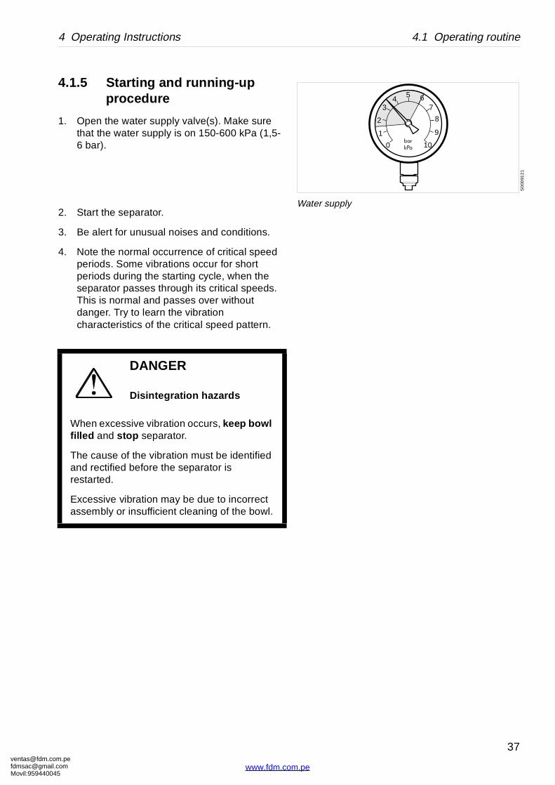
Water supply
4.1.5 Starting and running-up procedure
1. Open the water supply valve(s). Make sure that the water supply is on 150-600 kPa (1,5-6 bar).
2. Start the separator.
3. Be alert for unusual noises and conditions.
4. Note the normal occurrence of critical speed periods. Some vibrations occur for short periods during the starting cycle, when the separator passes through its critical speeds. This is normal and passes over without danger. Try to learn the vibration characteristics of the critical speed pattern.
DANGER
Disintegration hazards
When excessive vibration occurs, keep bowl filled and stop separator.
The cause of the vibration must be identified and rectified before the separator is restarted.
Excessive vibration may be due to incorrect assembly or insufficient cleaning of the bowl.
om.peil.com45
37
www.fdm.com.pe
ventafdmsaMovil:
4.1 Operating routine 4 Operating Instructions
S0
009
621
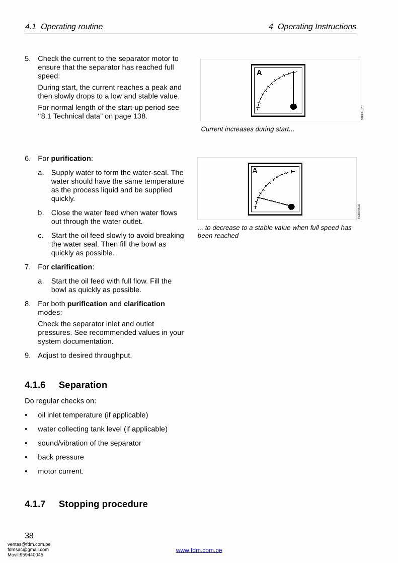
Current increases during start...
S00
096
31
... to decrease to a stable value when full speed has been reached
5. Check the current to the separator motor to ensure that the separator has reached full speed:
During start, the current reaches a peak and then slowly drops to a low and stable value.
For normal length of the start-up period see ‘‘8.1 Technical data” on page 138.
6. For purification :
a. Supply water to form the water-seal. The water should have the same temperature as the process liquid and be supplied quickly.
b. Close the water feed when water flows out through the water outlet.
c. Start the oil feed slowly to avoid breaking the water seal. Then fill the bowl as quickly as possible.
7. For clarification :
a. Start the oil feed with full flow. Fill the bowl as quickly as possible.
8. For both purification and clarification modes:
Check the separator inlet and outlet pressures. See recommended values in your system documentation.
9. Adjust to desired throughput.
4.1.6 Separation
Do regular checks on:
• oil inlet temperature (if applicable)
• water collecting tank level (if applicable)
• sound/vibration of the separator
• back pressure
• motor current.
4.1.7 Stopping procedure
[email protected]@gmail.com959440045
38
www.fdm.com.pe

[email protected]@gmaMovil:9594400
4 Operating Instructions 4.1 Operating routine
S00
5111
1
The separator must not be dismantled before standstill
1. Turn off the oil feed.
2. Feed displacement water until water flows out through the water outlet. Then close this feed.
3. Stop the separator.
4. Wait until the separator has come to a complete standstill (13-15 minutes).
Remove the safety device and look through the slot in the frame hood to see the movement of the bowl.
DANGER
Entrapment hazards
Make sure that rotating parts have come to a complete standstill before starting any dismantling work.
om.peil.com45
39
www.fdm.com.pe
ventafdmsaMovil:
4.1 Operating routine 4 Operating Instructions
S0
0556
11
Hazard!
S00
099
11
Push the safety stop!
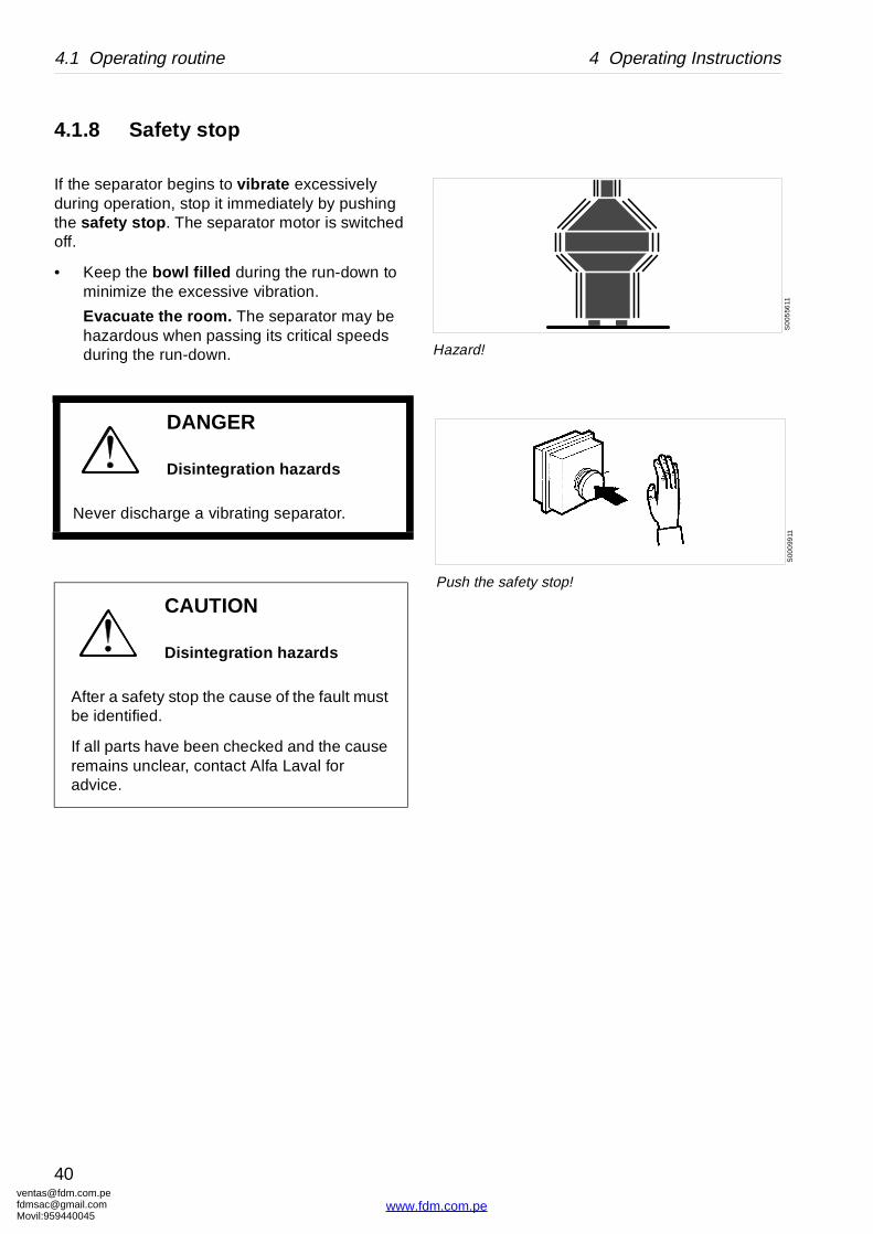
4.1.8 Safety stop
If the separator begins to vibrate excessively during operation, stop it immediately by pushing the safety stop . The separator motor is switched off.
• Keep the bowl filled during the run-down to minimize the excessive vibration.
Evacuate the room. The separator may be hazardous when passing its critical speeds during the run-down.
DANGER
Disintegration hazards
Never discharge a vibrating separator.
CAUTION
Disintegration hazards
After a safety stop the cause of the fault must be identified.
If all parts have been checked and the cause remains unclear, contact Alfa Laval for advice.
[email protected]@gmail.com959440045
40
www.fdm.com.pe

[email protected]@gmaMovil:9594400
5 Service Instructions
Contents
5.1 Periodic maintenance 42
5.1.1 Introduction 42
5.1.2 Maintenance intervals 42
5.1.3 Maintenance procedure 44
5.1.4 Service kits 44
5.2 Maintenance Logs 45
5.2.1 Daily checks 45
5.2.2 Oil change - monthly 46
5.2.3 IS - Intermediate Service 47
5.2.4 MS - Major Service 49
5.3 Check points at Intermediate Service 51
5.3.1 Corrosion 51
5.3.2 Erosion 53
5.3.3 Cracks 54
5.3.4 Discharge mechanism 55
5.3.5 Bowl hood and sliding bowl bottom 56
5.3.6 Spindle top cone and bowl body nave 58
5.3.7 Threads of inlet pipe, paring disc 59
5.3.8 Threads on bowl hood and bowl body 60
5.3.9 Disc stack pressure 62
5.4 Check points at Major Service 63
5.4.1 Paring disc height adjustment 63
5.4.2 Radial wobble of bowl spindle 64
om.peil.com45
www.fdm.co
5.5 3-year service 65
5.6 Lifting instructions 66
5.7 Cleaning 68
5.7.1 Cleaning agents 69
5.7.2 Cleaning of bowl discs 70
5.8 Oil change 71
5.8.1 Oil change procedure 71
5.9 Vibration 73
5.9.1 Vibration analysis 73
5.10 General directions 74
5.10.1 Ball and roller bearings 74
5.10.2 Before shut-downs 77
41
m.pe
ventafdmsaMovil:
5.1 Periodic maintenance 5 Service Instructions
5.1 Periodic maintenance
5.1.1 Introduction
Periodic, preventive maintenance reduces the risk of unexpected stoppages and breakdowns. Maintenance logs are shown on the following pages in order to facilitate periodic maintenance.
5.1.2 Maintenance intervals
The following directions for periodic maintenance give a brief description of which parts to clean, check and renew at different maintenance intervals.
The service logs for each maintenance interval later in this chapter give detailed enumeration of the checks that must be done.
Daily checks consist of simple check points to carry out for detecting abnormal operating conditions.
Oil change interval is 1500 hours. If the total number of operating hours is less than 1500 hours change oil at least once every year.
Time of operation between oil changes can be extended from the normal 1500 hours to 2000 hours if a synthetic oil of group D is used.
In seasonal operation change the oil before a new period.
IS - Intermediate Service consists of an overhaul of the separator bowl, inlet and outlet every 3 months or 2000 operating hours. Seals in bowl and gaskets in the inlet/outlet device and operating device are renewed.
DANGER
Disintegration hazards
Separator parts that are worn beyond their safe limits or incorrectly assembled may cause severe damage or fatal injury.
[email protected]@gmail.com959440045
42
www.fdm.com.pe
[email protected]@gmaMovil:9594400
5 Service Instructions 5.1 Periodic maintenance
r
dule
3-year Service
MS MSIS IS IS IS IS IS IS IS
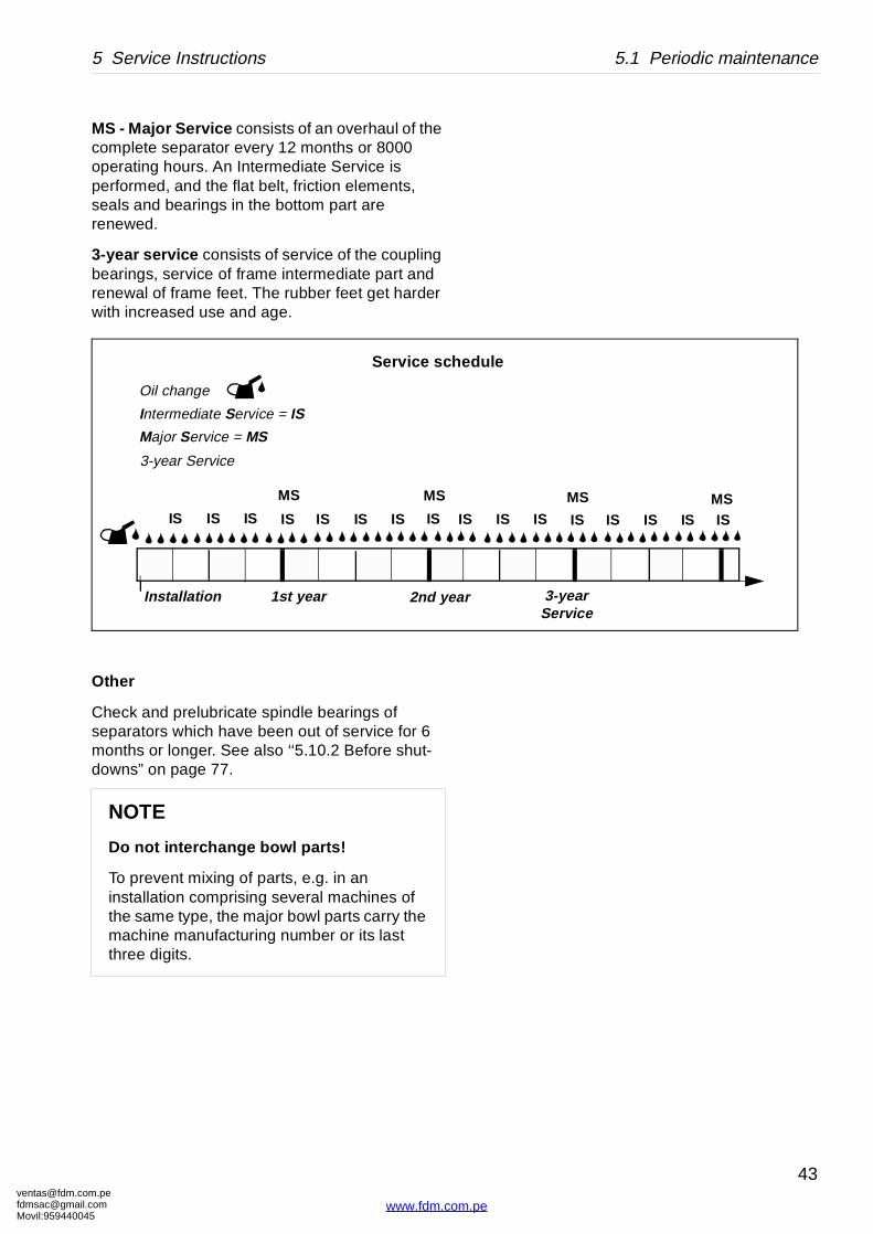
MS - Major Service consists of an overhaul of the complete separator every 12 months or 8000 operating hours. An Intermediate Service is performed, and the flat belt, friction elements, seals and bearings in the bottom part are renewed.
3-year service consists of service of the coupling bearings, service of frame intermediate part and renewal of frame feet. The rubber feet get harder with increased use and age.
Other
Check and prelubricate spindle bearings of separators which have been out of service for 6 months or longer. See also ‘‘5.10.2 Before shut-downs” on page 77.
NOTE
Do not interchange bowl parts!
To prevent mixing of parts, e.g. in an installation comprising several machines of the same type, the major bowl parts carry the machine manufacturing number or its last three digits.
2nd yea
Oil change
Intermediate Service = IS
Major Service = MS
Service sche
Installation 1st year
MS MS
IS IS IS IS IS IS IS IS
3-year Service
om.peil.com45
43
www.fdm.com.pe
ventafdmsaMovil:
5.1 Periodic maintenance 5 Service Instructions
S0
0210
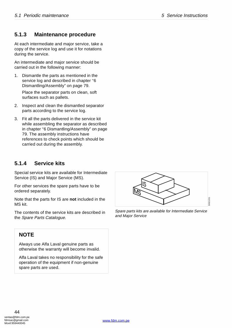
31
Spare parts kits are available for Intermediate Service and Major Service
5.1.3 Maintenance procedure
At each intermediate and major service, take a copy of the service log and use it for notations during the service.
An intermediate and major service should be carried out in the following manner:
1. Dismantle the parts as mentioned in the service log and described in chapter ‘‘6 Dismantling/Assembly” on page 79.
Place the separator parts on clean, soft surfaces such as pallets.
2. Inspect and clean the dismantled separator parts according to the service log.
3. Fit all the parts delivered in the service kit while assembling the separator as described in chapter ‘‘6 Dismantling/Assembly” on page 79. The assembly instructions have references to check points which should be carried out during the assembly.
5.1.4 Service kits
Special service kits are available for Intermediate Service (IS) and Major Service (MS).
For other services the spare parts have to be ordered separately.
Note that the parts for IS are not included in the MS kit.
The contents of the service kits are described in the Spare Parts Catalogue.
NOTE
Always use Alfa Laval genuine parts as otherwise the warranty will become invalid.
Alfa Laval takes no responsibility for the safe operation of the equipment if non-genuine spare parts are used.
[email protected]@gmail.com959440045
44
www.fdm.com.pe
[email protected]@gmaMovil:9594400
5 Service Instructions 5.2 Maintenance Logs
Page Notes
g housing 36
37
37
36
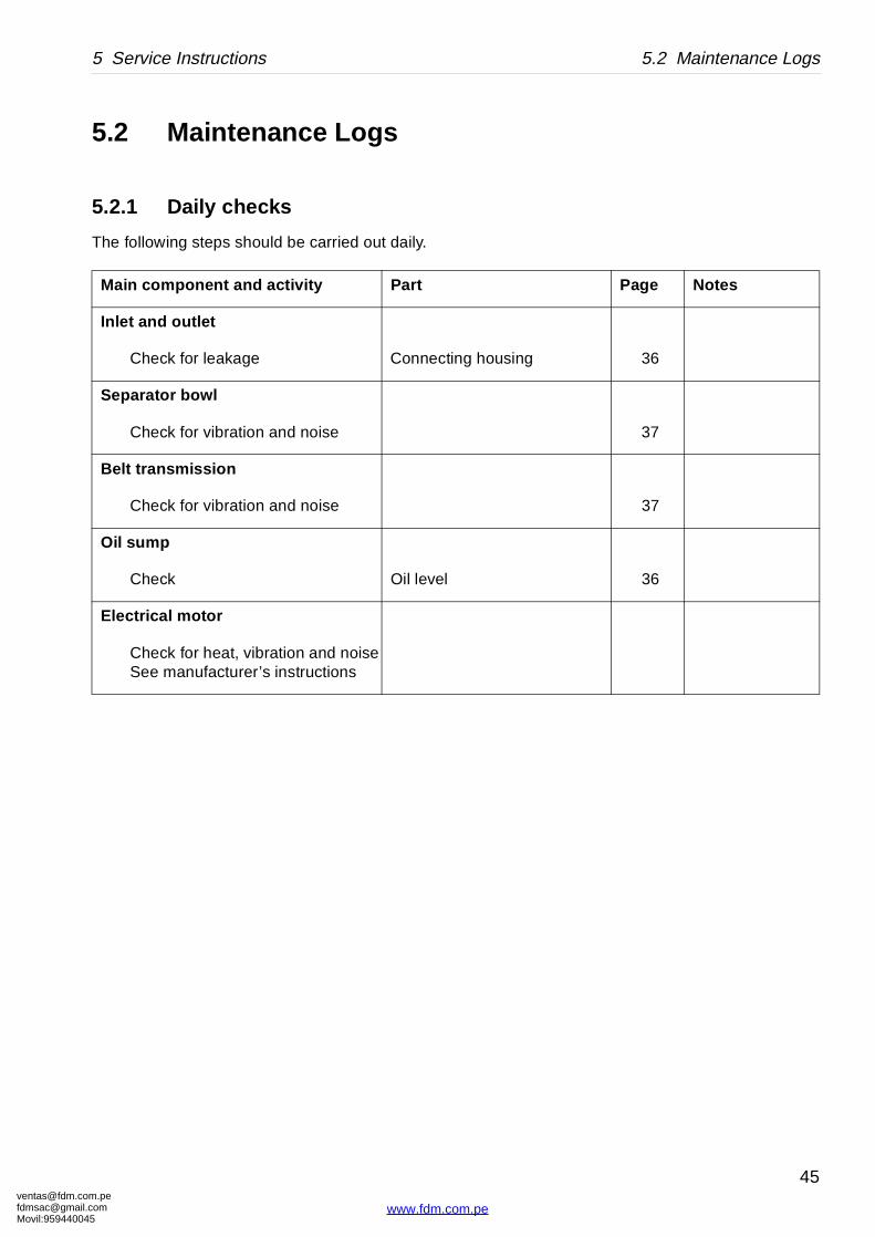
5.2 Maintenance Logs
5.2.1 Daily checks
The following steps should be carried out daily.
Main component and activity Part
Inlet and outlet
Check for leakage Connectin
Separator bowl
Check for vibration and noise
Belt transmission
Check for vibration and noise
Oil sump
Check Oil level
Electrical motor
Check for heat, vibration and noiseSee manufacturer’s instructions
om.peil.com45
45
www.fdm.com.pe
ventafdmsaMovil:
5.2 Maintenance Logs 5 Service Instructions
Page Notes
n 116
ump 71
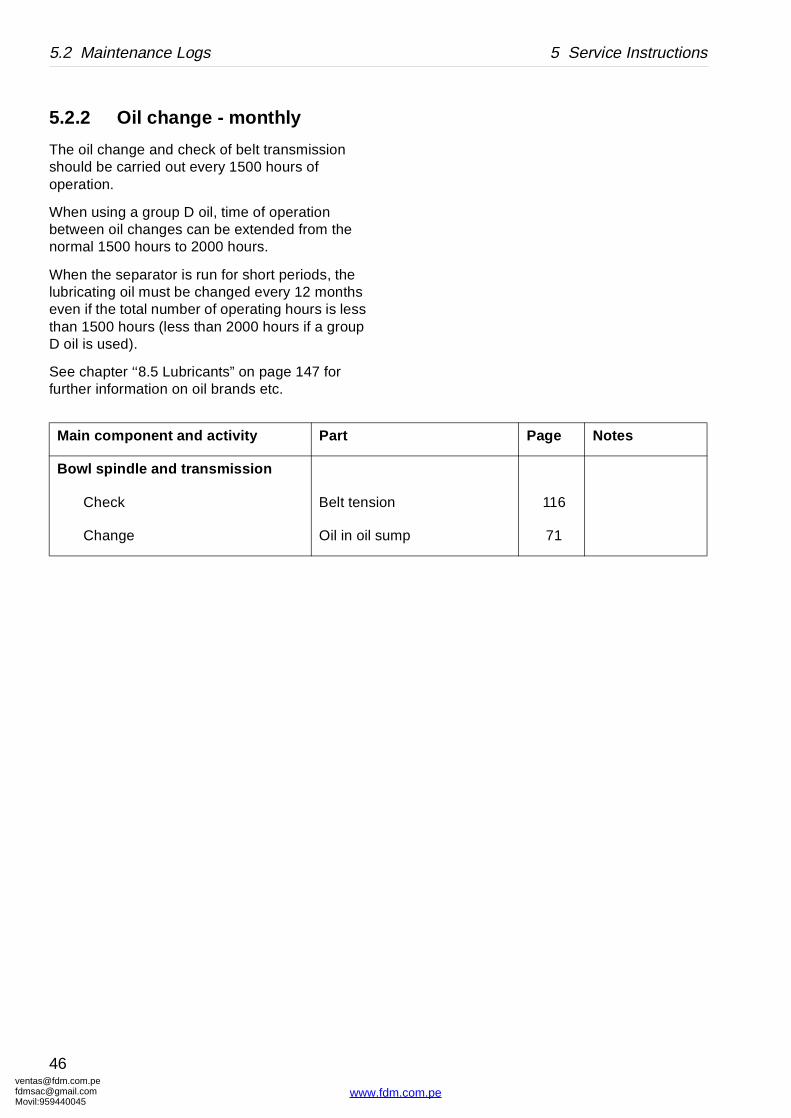
5.2.2 Oil change - monthly
The oil change and check of belt transmission should be carried out every 1500 hours of operation.
When using a group D oil, time of operation between oil changes can be extended from the normal 1500 hours to 2000 hours.
When the separator is run for short periods, the lubricating oil must be changed every 12 months even if the total number of operating hours is less than 1500 hours (less than 2000 hours if a group D oil is used).
See chapter ‘‘8.5 Lubricants” on page 147 for further information on oil brands etc.
Main component and activity Part
Bowl spindle and transmission
Check Belt tensio
Change Oil in oil s
[email protected]@gmail.com959440045
46
www.fdm.com.pe
[email protected]@gmaMovil:9594400
5 Service Instructions 5.2 Maintenance Logs
ocal identification:
anufacture No./Year:
roduct No.: 881099-01-04
ignature:
kit (IS) and do the following activities.
Page Notes
inlet pipe 59
59
nd frame hood -
60
70
70
-
bowl body 55
l bottom 56
mechanism 55
bowl hood and 60
le cone and bowl 58
pressure 62
uide surface 60
erosion, cracks 51 - 53
lt tension 116
mp 71
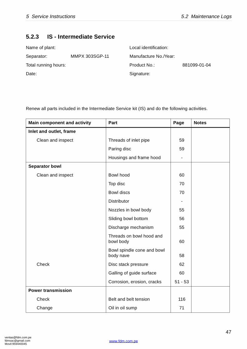
5.2.3 IS - Intermediate Service
Name of plant: L
Separator: MMPX 303SGP-11 M
Total running hours: P
Date: S
Renew all parts included in the Intermediate Service
Main component and activity Part
Inlet and outlet, frame
Clean and inspect Threads of
Paring disc
Housings a
Separator bowl
Clean and inspect Bowl hood
Top disc
Bowl discs
Distributor
Nozzles in
Sliding bow
Discharge
Threads onbowl body
Bowl spindbody nave
Check Disc stack
Galling of g
Corrosion,
Power transmission
Check Belt and be
Change Oil in oil su
om.peil.com45
47
www.fdm.com.pe
ventafdmsaMovil:
5.2 Maintenance Logs 5 Service Instructions
n motor -
l on hood 164
s and labels 164
Page Notes
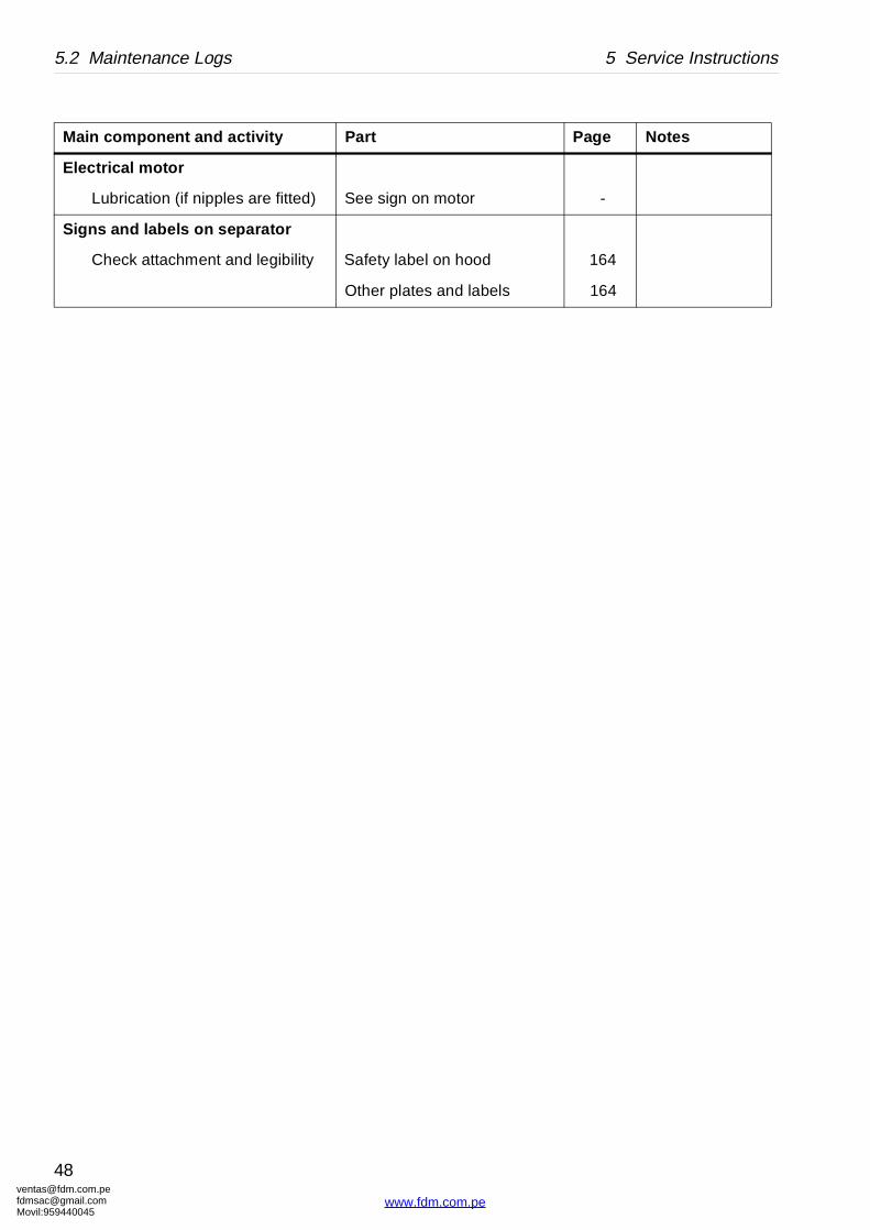
Electrical motor
Lubrication (if nipples are fitted) See sign o
Signs and labels on separator
Check attachment and legibility Safety labe
Other plate
Main component and activity Part
[email protected]@gmail.com959440045
48
www.fdm.com.pe
[email protected]@gmaMovil:9594400
5 Service Instructions 5.2 Maintenance Logs
ocal identification:
anufacture No./Year:
roduct No.: 881099-01-04
ignature:
jor Service kits and do the following
Page Notes
inlet pipe 59
59
nd frame hood -
60
70
70
–
bowl body 55
l bottom 56
mechanism 55
bowl hood and 60
le cone and bowl 58
aring disc 63
pressure 62
uide surface 60
erosion, cracks 51 - 53
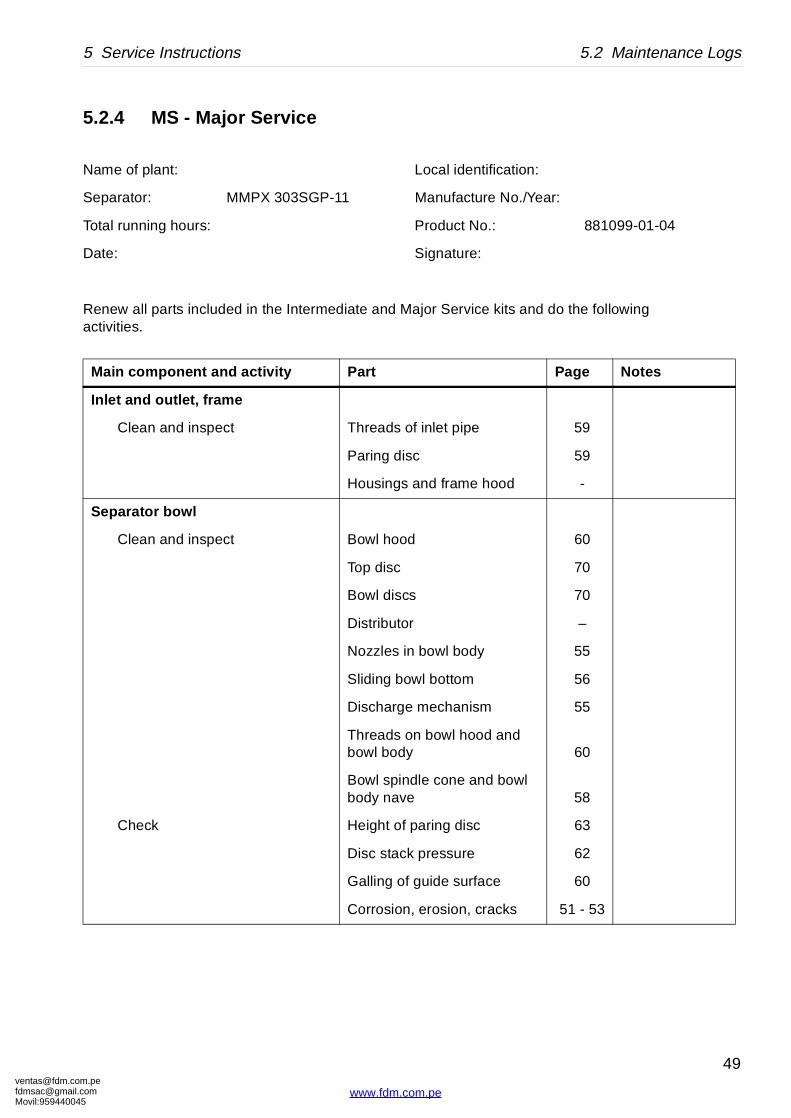
5.2.4 MS - Major Service
Name of plant: L
Separator: MMPX 303SGP-11 M
Total running hours: P
Date: S
Renew all parts included in the Intermediate and Maactivities.
Main component and activity Part
Inlet and outlet, frame
Clean and inspect Threads of
Paring disc
Housings a
Separator bowl
Clean and inspect Bowl hood
Top disc
Bowl discs
Distributor
Nozzles in
Sliding bow
Discharge
Threads onbowl body
Bowl spindbody nave
Check Height of p
Disc stack
Galling of g
Corrosion,
om.peil.com45
49
www.fdm.com.pe
ventafdmsaMovil:
5.2 Maintenance Logs 5 Service Instructions
108
108
122
ve
le 99
g housing s 99
ble of bowl spindle 64
71
71
vice 121
pling 110
l on hood 164
and labels 164
Page Notes
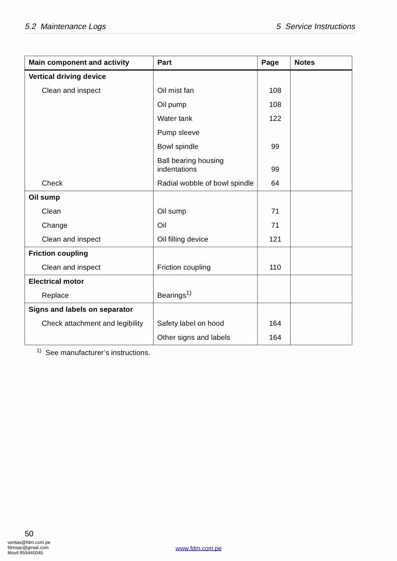
1) See manufacturer’s instructions.
Vertical driving device
Clean and inspect Oil mist fan
Oil pump
Water tank
Pump slee
Bowl spind
Ball bearinindentation
Check Radial wob
Oil sump
Clean Oil sump
Change Oil
Clean and inspect Oil filling de
Friction c oupling
Clean and inspect Friction cou
Electrical motor
Replace Bearings1)
Signs and labels on separator
Check attachment and legibility Safety labe
Other signs
Main component and activity Part
[email protected]@gmail.com959440045
50
www.fdm.com.pe
[email protected]@gmaMovil:9594400
5 Service Instructions 5.3 Check points at Intermediate Service
G0
172
111
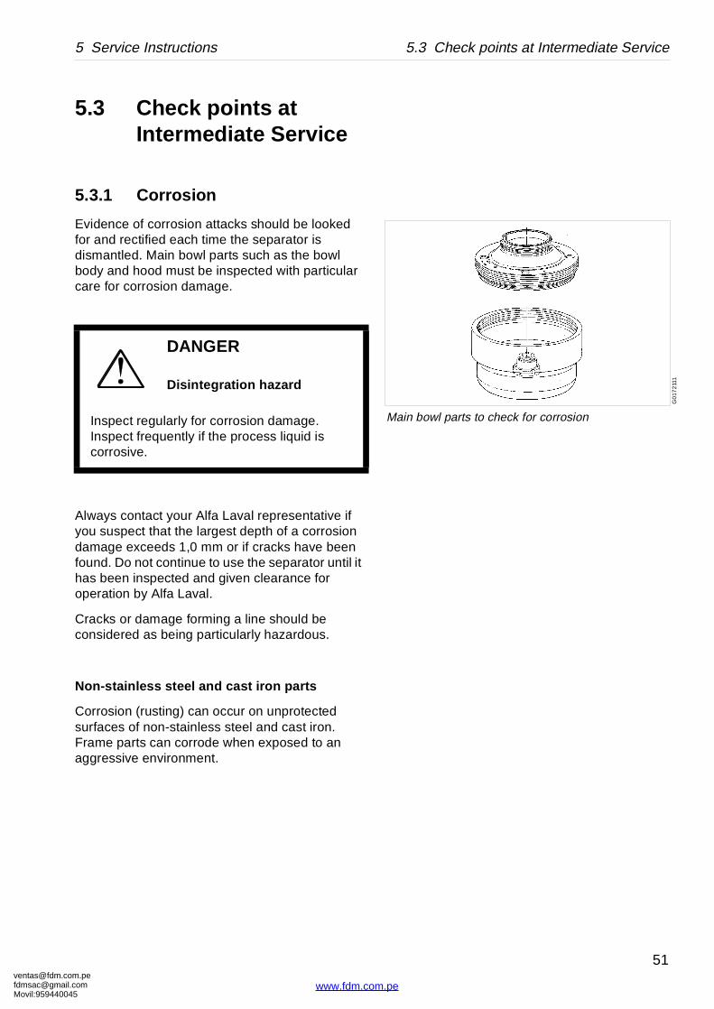
Main bowl parts to check for corrosion
5.3 Check points at Intermediate Service
5.3.1 Corrosion
Evidence of corrosion attacks should be looked for and rectified each time the separator is dismantled. Main bowl parts such as the bowl body and hood must be inspected with particular care for corrosion damage.
Always contact your Alfa Laval representative if you suspect that the largest depth of a corrosion damage exceeds 1,0 mm or if cracks have been found. Do not continue to use the separator until it has been inspected and given clearance for operation by Alfa Laval.
Cracks or damage forming a line should be considered as being particularly hazardous.
Non-s tainless steel and cast iron parts
Corrosion (rusting) can occur on unprotected surfaces of non-stainless steel and cast iron. Frame parts can corrode when exposed to an aggressive environment.
DANGER
Disintegration hazard
Inspect regularly for corrosion damage. Inspect frequently if the process liquid is corrosive.
om.peil.com45
51
www.fdm.com.pe
ventafdmsaMovil:
5.3 Check points at Intermediate Service 5 Service Instructions
S0
0206
11
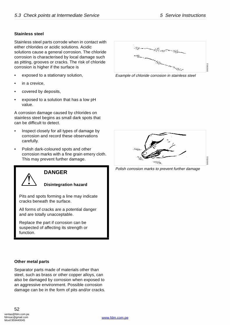
Example of chloride corrosion in stainless steel
S0
0205
11
Polish corrosion marks to prevent further damage
Stainless steel
Stainless steel parts corrode when in contact with either chlorides or acidic solutions. Acidic solutions cause a general corrosion. The chloride corrosion is characterised by local damage such as pitting, grooves or cracks. The risk of chloride corrosion is higher if the surface is
• exposed to a stationary solution,
• in a crevice,
• covered by deposits,
• exposed to a solution that has a low pH value.
A corrosion damage caused by chlorides on stainless steel begins as small dark spots that can be difficult to detect.
• Inspect closely for all types of damage by corrosion and record these observations carefully.
• Polish dark-coloured spots and other corrosion marks with a fine grain emery cloth. This may prevent further damage.
Other me tal parts
Separator parts made of materials other than steel, such as brass or other copper alloys, can also be damaged by corrosion when exposed to an aggressive environment. Possible corrosion damage can be in the form of pits and/or cracks.
DANGER
Disintegration hazard
Pits and spots forming a line may indicate cracks beneath the surface.
All forms of cracks are a potential danger and are totally unacceptable.
Replace the part if corrosion can be suspected of affecting its strength or function.
[email protected]@gmail.com959440045
52
www.fdm.com.pe
[email protected]@gmaMovil:9594400
5 Service Instructions 5.3 Check points at Intermediate Service
G02
0522
1
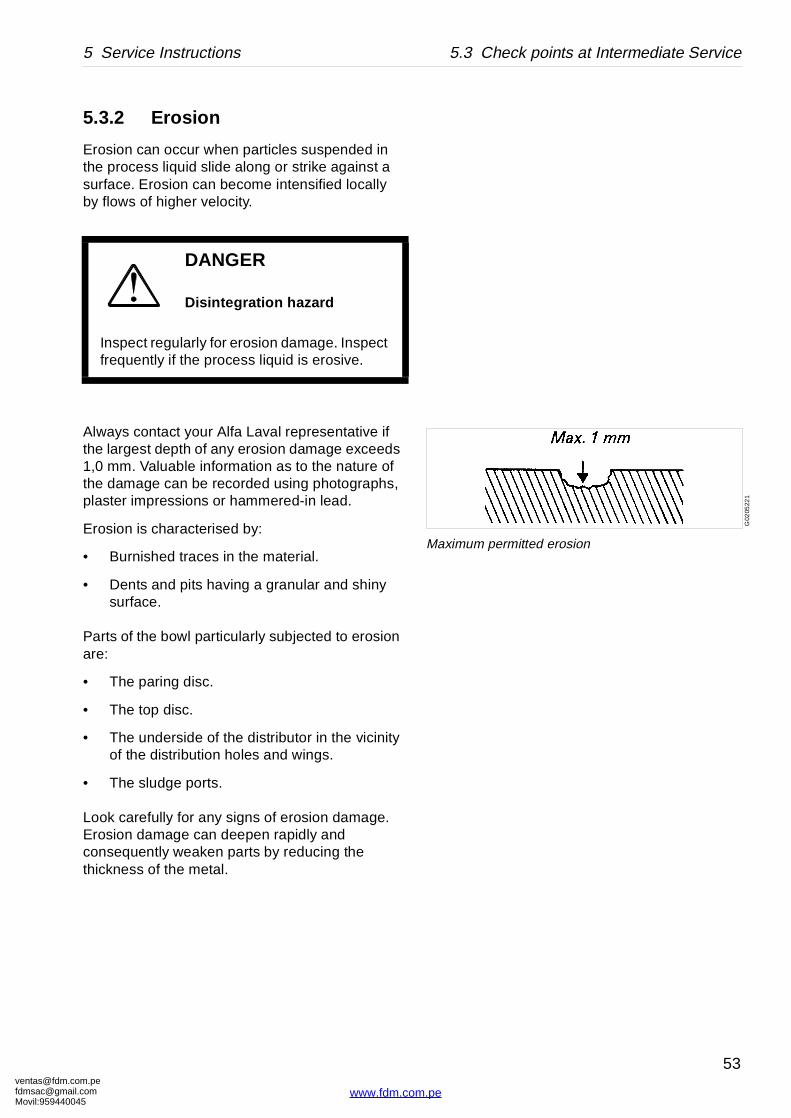
Maximum permitted erosion
5.3.2 Erosion
Erosion can occur when particles suspended in the process liquid slide along or strike against a surface. Erosion can become intensified locally by flows of higher velocity.
Always contact your Alfa Laval representative if the largest depth of any erosion damage exceeds 1,0 mm. Valuable information as to the nature of the damage can be recorded using photographs, plaster impressions or hammered-in lead.
Erosion is characterised by:
• Burnished traces in the material.
• Dents and pits having a granular and shiny surface.
Parts of the bowl particularly subjected to erosion are:
• The paring disc.
• The top disc.
• The underside of the distributor in the vicinity of the distribution holes and wings.
• The sludge ports.
Look carefully for any signs of erosion damage. Erosion damage can deepen rapidly and consequently weaken parts by reducing the thickness of the metal.
DANGER
Disintegration hazard
Inspect regularly for erosion damage. Inspect frequently if the process liquid is erosive.
om.peil.com45
53
www.fdm.com.pe
ventafdmsaMovil:
5.3 Check points at Intermediate Service 5 Service Instructions
5.3.3 Cracks
Cracks can initiate on the machine after a period of operation and propagate with time.
• Cracks often initiate in areas exposed to high cyclic material stresses. These cracks are called fatigue cracks.
• Cracks can also initiate due to corrosion in an aggressive environment.
• Although very unlikely, cracks may also occur due to the low temperature embrittlement of certain materials.
The combination of an aggressive environment and cyclic stresses will speed-up the formation of cracks. Keeping the machine and its parts clean and free from deposits will help to prevent corrosion attacks.
It is particularly important to inspect for cracks in rotating parts.
Always contact your Alfa Laval representative if you suspect that the largest depth of the damage exceeds 1,0 mm. Do not continue to use the separator until it has been inspected and cleared for operation by Alfa Laval.
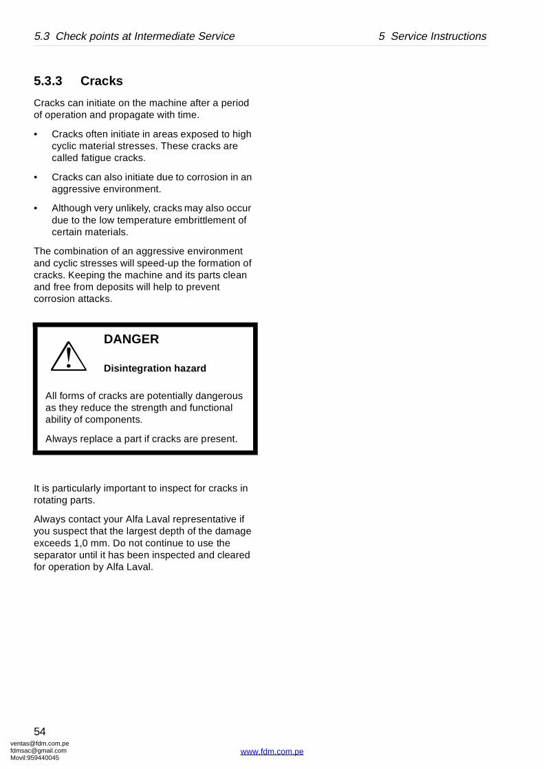
DANGER
Disintegration hazard
All forms of cracks are potentially dangerous as they reduce the strength and functional ability of components.
Always replace a part if cracks are present.
[email protected]@gmail.com959440045
54
www.fdm.com.pe
[email protected]@gmaMovil:9594400
5 Service Instructions 5.3 Check points at Intermediate Service
G01
2151
1
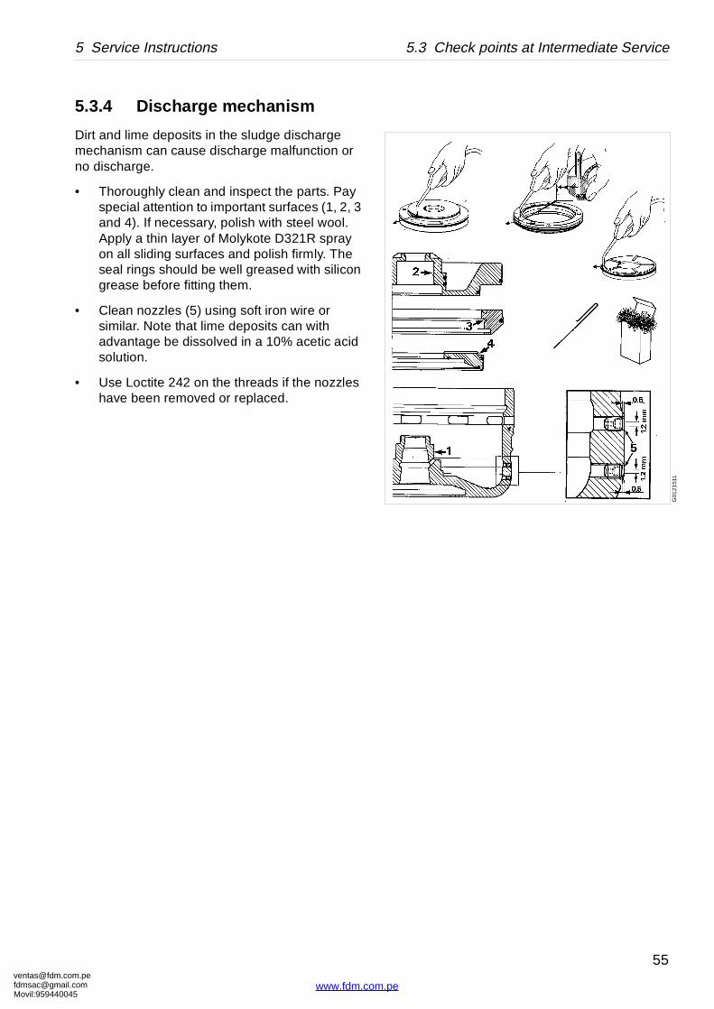
5.3.4 Discharge mechanism
Dirt and lime deposits in the sludge discharge mechanism can cause discharge malfunction or no discharge.
• Thoroughly clean and inspect the parts. Pay special attention to important surfaces (1, 2, 3 and 4). If necessary, polish with steel wool. Apply a thin layer of Molykote D321R spray on all sliding surfaces and polish firmly. The seal rings should be well greased with silicon grease before fitting them.
• Clean nozzles (5) using soft iron wire or similar. Note that lime deposits can with advantage be dissolved in a 10% acetic acid solution.
• Use Loctite 242 on the threads if the nozzles have been removed or replaced.
om.peil.com45
55
www.fdm.com.pe
ventafdmsaMovil:
5.3 Check points at Intermediate Service 5 Service Instructions
G00
7102
1
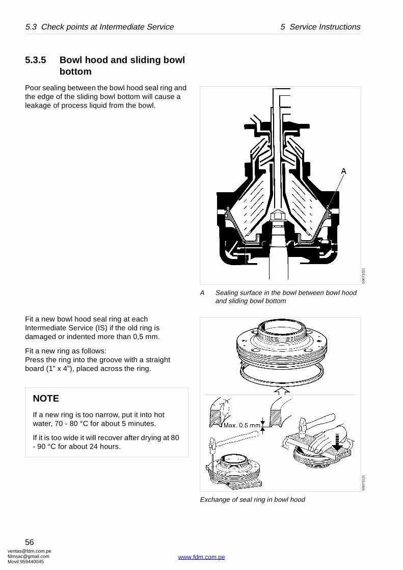
A Sealing surface in the bowl between bowl hood and sliding bowl bottom
G00
711
21
Exchange of seal ring in bowl hood
5.3.5 Bowl hood and sliding bowl bottom
Poor sealing between the bowl hood seal ring and the edge of the sliding bowl bottom will cause a leakage of process liquid from the bowl.
Fit a new bowl hood seal ring at each Intermediate Service (IS) if the old ring is damaged or indented more than 0,5 mm.
Fit a new ring as follows:Press the ring into the groove with a straight board (1” x 4”), placed across the ring.
NOTE
If a new ring is too narrow, put it into hot water, 70 - 80 °C for about 5 minutes.
If it is too wide it will recover after drying at 80 - 90 °C for about 24 hours.
[email protected]@gmail.com959440045
56
www.fdm.com.pe

[email protected]@gmaMovil:9594400
5 Service Instructions 5.3 Check points at Intermediate Service
G00
712
21
a Sealing edge on sliding bowl bottom
G0
071
231
Removal of seal ring on sliding bowl bottom
Check the sealing edge (a) of the sliding bowl bottom.
If damaged through corrosion or erosion or in other ways it can be rectified by turning in a lathe. Minimum permissible height of sealing edge: 4,5 mm.
om.peil.com45
57
www.fdm.com.pe
ventafdmsaMovil:
5.3 Check points at Intermediate Service 5 Service Instructions
G0
0716
11
Use whetstone or scraper with great care
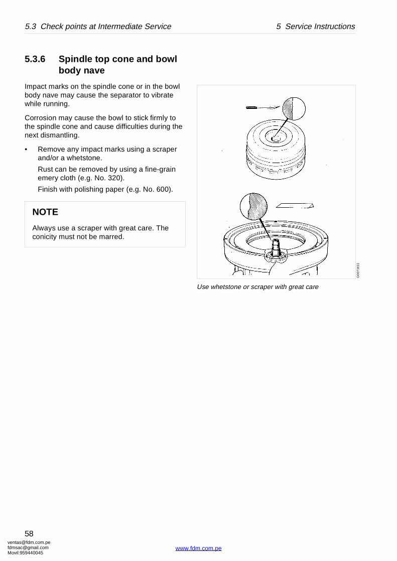
5.3.6 Spindle top cone and bowl body nave
Impact marks on the spindle cone or in the bowl body nave may cause the separator to vibrate while running.
Corrosion may cause the bowl to stick firmly to the spindle cone and cause difficulties during the next dismantling.
• Remove any impact marks using a scraper and/or a whetstone.
Rust can be removed by using a fine-grain emery cloth (e.g. No. 320).
Finish with polishing paper (e.g. No. 600).
NOTE
Always use a scraper with great care. The conicity must not be marred.
[email protected]@gmail.com959440045
58
www.fdm.com.pe
[email protected]@gmaMovil:9594400
5 Service Instructions 5.3 Check points at Intermediate Service
G01
130
21
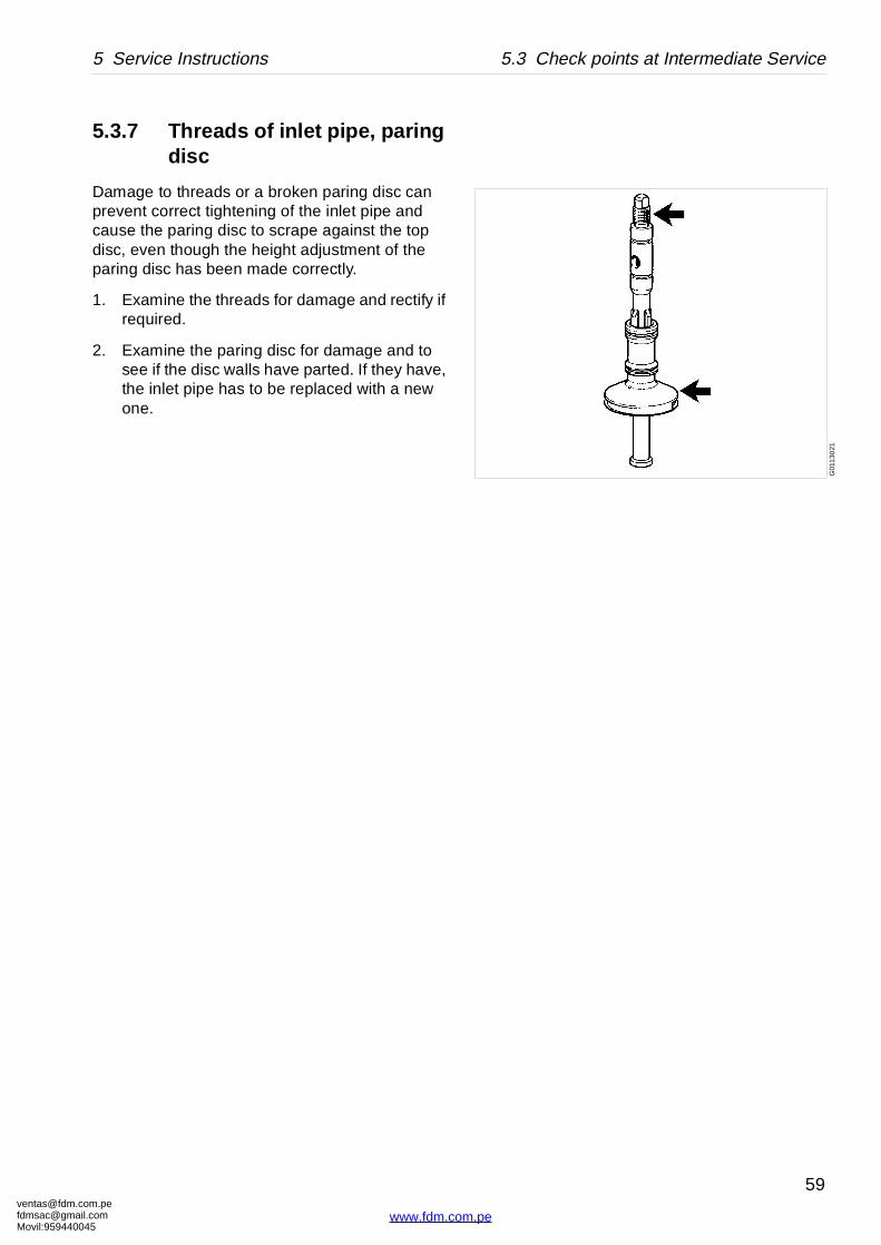
5.3.7 Threads of inlet pipe, paring disc
Damage to threads or a broken paring disc can prevent correct tightening of the inlet pipe and cause the paring disc to scrape against the top disc, even though the height adjustment of the paring disc has been made correctly.
1. Examine the threads for damage and rectify if required.
2. Examine the paring disc for damage and to see if the disc walls have parted. If they have, the inlet pipe has to be replaced with a new one.
om.peil.com45
59
www.fdm.com.pe

ventafdmsaMovil:
5.3 Check points at Intermediate Service 5 Service Instructions
G00
7131
1
D
A
(MAX 25 )G
057
8111
5.3.8 Threads on bowl hood and bowl body
Excessive wear or impact marks on threads and guide surfaces of the bowl hood or bowl body can cause seizure damage.
Examine the thread condition by tightening the bowl hood after removing the disc stack and top disc from the bowl.
When the bowl is new the alignment marks on the bowl hood and the bowl body should be aligned. If not, contact an Alfa Laval representative.
Wear
If thread wear is observed, mark the bowl body at the new position by punching a new alignment mark. If the mark on the bowl hood passes the mark on the bowl body by more than 25°, (A in the illustration) an Alfa Laval representative should be contacted immediately.
The measure A in millimetres (mm) is obtained by calculating bowl outside diameter D times 0,2.
If the marks are illegible, an Alfa Laval representative should be contacted for determination and punching of new alignment marks.
DANGER
Disintegration hazards
Wear on threads must not exceed safety limit. φ mark on bowl hood must not pass φ mark on bowl body by more than 25°.
[email protected]@gmail.com959440045
60
www.fdm.com.pe
[email protected]@gmaMovil:9594400
5 Service Instructions 5.3 Check points at Intermediate Service
G0
071
511
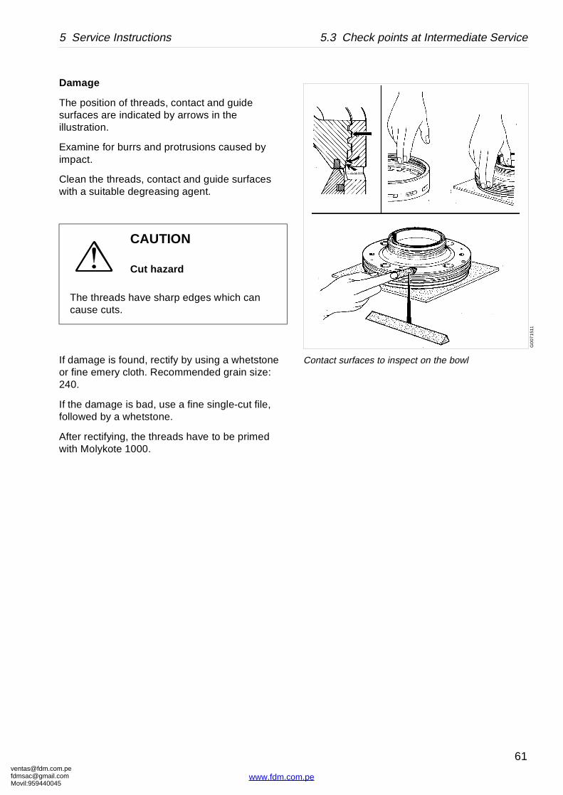
Contact surfaces to inspect on the bowl
Damage
The position of threads, contact and guide surfaces are indicated by arrows in the illustration.
Examine for burrs and protrusions caused by impact.
Clean the threads, contact and guide surfaces with a suitable degreasing agent.
If damage is found, rectify by using a whetstone or fine emery cloth. Recommended grain size: 240.
If the damage is bad, use a fine single-cut file, followed by a whetstone.
After rectifying, the threads have to be primed with Molykote 1000.
CAUTION
Cut hazard
The threads have sharp edges which can cause cuts.
om.peil.com45
61
www.fdm.com.pe
ventafdmsaMovil:
5.3 Check points at Intermediate Service 5 Service Instructions
G00
7191
1
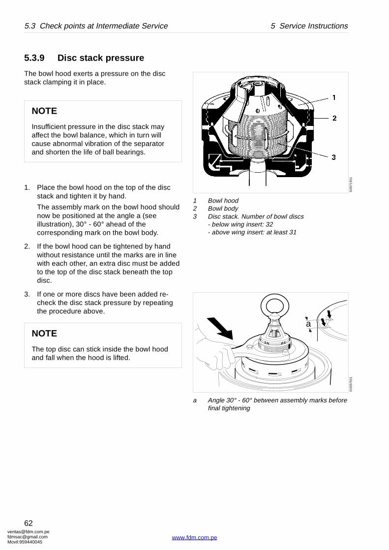
1 Bowl hood2 Bowl body3 Disc stack. Number of bowl discs
- below wing insert: 32- above wing insert: at least 31
a
G03
5761
1
a Angle 30° - 60° between assembly marks before final tightening
5.3.9 Disc stack pressure
The bowl hood exerts a pressure on the disc stack clamping it in place.
1. Place the bowl hood on the top of the disc stack and tighten it by hand.
The assembly mark on the bowl hood should now be positioned at the angle a (see illustration), 30° - 60° ahead of the corresponding mark on the bowl body.
2. If the bowl hood can be tightened by hand without resistance until the marks are in line with each other, an extra disc must be added to the top of the disc stack beneath the top disc.
3. If one or more discs have been added re-check the disc stack pressure by repeating the procedure above.
NOTE
Insufficient pressure in the disc stack may affect the bowl balance, which in turn will cause abnormal vibration of the separator and shorten the life of ball bearings.
NOTE
The top disc can stick inside the bowl hood and fall when the hood is lifted.
[email protected]@gmail.com959440045
62
www.fdm.com.pe
[email protected]@gmaMovil:9594400
5 Service Instructions 5.4 Check points at Major Service
G0
0728
21G
00
7295
1G
0172
931
5.4 Check points at Major Service
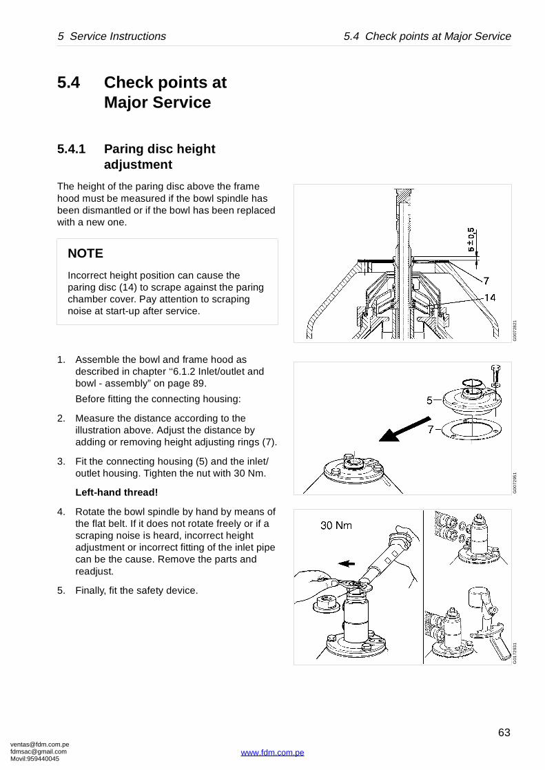
5.4.1 Paring disc height adjustment
The height of the paring disc above the frame hood must be measured if the bowl spindle has been dismantled or if the bowl has been replaced with a new one.
1. Assemble the bowl and frame hood as described in chapter ‘‘6.1.2 Inlet/outlet and bowl - assembly” on page 89.
Before fitting the connecting housing:
2. Measure the distance according to the illustration above. Adjust the distance by adding or removing height adjusting rings (7).
3. Fit the connecting housing (5) and the inlet/outlet housing. Tighten the nut with 30 Nm.
Left-hand thread!
4. Rotate the bowl spindle by hand by means of the flat belt. If it does not rotate freely or if a scraping noise is heard, incorrect height adjustment or incorrect fitting of the inlet pipe can be the cause. Remove the parts and readjust.
5. Finally, fit the safety device.
NOTE
Incorrect height position can cause the paring disc (14) to scrape against the paring chamber cover. Pay attention to scraping noise at start-up after service.
om.peil.com45
63
www.fdm.com.pe
ventafdmsaMovil:
5.4 Check points at Major Service 5 Service Instructions
G0
1212
11
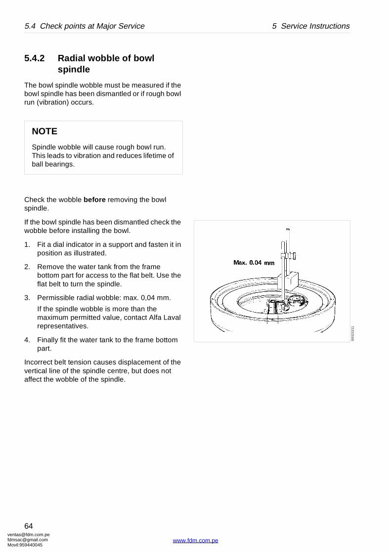
5.4.2 Radial wobble of bowl spindle
The bowl spindle wobble must be measured if the bowl spindle has been dismantled or if rough bowl run (vibration) occurs.
Check the wobble before removing the bowl spindle.
If the bowl spindle has been dismantled check the wobble before installing the bowl.
1. Fit a dial indicator in a support and fasten it in position as illustrated.
2. Remove the water tank from the frame bottom part for access to the flat belt. Use the flat belt to turn the spindle.
3. Permissible radial wobble: max. 0,04 mm.
If the spindle wobble is more than the maximum permitted value, contact Alfa Laval representatives.
4. Finally fit the water tank to the frame bottom part.
Incorrect belt tension causes displacement of the vertical line of the spindle centre, but does not affect the wobble of the spindle.
NOTE
Spindle wobble will cause rough bowl run. This leads to vibration and reduces lifetime of ball bearings.
[email protected]@gmail.com959440045
64
www.fdm.com.pe
[email protected]@gmaMovil:9594400
5 Service Instructions 5.5 3-year service
5.5 3-year service
Exchange of frame feet
See ‘‘6.7.1 Mounting of new frame feet” on page 123.
Friction coupling
Exchange of ball bearings, see ‘‘6.3 Friction coupling” on page 110.
Frame intermediate part
Replace O-ring and gasket, see ‘‘6.2.2 Bowl spindle and frame - assembly” on page 104.
om.peil.com45
65
www.fdm.com.pe
ventafdmsaMovil:
5.6 Lifting instructions 5 Service Instructions
G05
0712
1
A <2 mm
G00
575
31
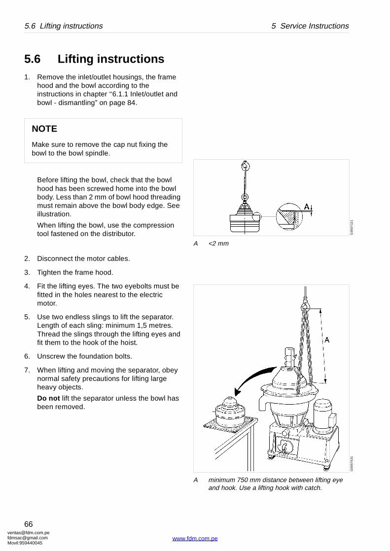
A minimum 750 mm distance between lifting eye and hook. Use a lifting hook with catch.
5.6 Lifting instructions1. Remove the inlet/outlet housings, the frame
hood and the bowl according to the instructions in chapter ‘‘6.1.1 Inlet/outlet and bowl - dismantling” on page 84.
Before lifting the bowl, check that the bowl hood has been screwed home into the bowl body. Less than 2 mm of bowl hood threading must remain above the bowl body edge. See illustration.
When lifting the bowl, use the compression tool fastened on the distributor.
2. Disconnect the motor cables.
3. Tighten the frame hood.
4. Fit the lifting eyes. The two eyebolts must be fitted in the holes nearest to the electric motor.
5. Use two endless slings to lift the separator. Length of each sling: minimum 1,5 metres. Thread the slings through the lifting eyes and fit them to the hook of the hoist.
6. Unscrew the foundation bolts.
7. When lifting and moving the separator, obey normal safety precautions for lifting large heavy objects.
Do not lift the separator unless the bowl has been removed.
NOTE
Make sure to remove the cap nut fixing the bowl to the bowl spindle.
[email protected]@gmail.com959440045
66
www.fdm.com.pe
[email protected]@gmaMovil:9594400
5 Service Instructions 5.6 Lifting instructions
8. Remove the lifting eyes afterwards.
WARNING
Crush hazards
Use only the two special lifting eyes (M12) for lifting the machine. They are to be screwed into the special threaded holes.
Other holes are not dimensioned for lifting the machine.
A falling separator can cause accidents resulting in serious injury and damage.
NOTE
Separator without bowl: Use lifting slings for WLL 300 kg.
Bowl: Use lifting slings for WLL 100 kg.
om.peil.com45
67
www.fdm.com.pe

ventafdmsaMovil:
G06
135
11
Use a brush and a sponge or cloth when cleaning
G0
6136
11
Never wash down a separator with a direct water stream or spray
5.7 CleaningExternal cleaning
The external cleaning of frame and motor should be restricted to brushing, sponging or wiping while the motor is running or is still hot.
Never wash down a separator with a direct water stream. Totally enclosed motors can be damaged by direct hosing to the same extent as open motors and even more than those, because:
• Many operators believe that these motors are sealed, and normally they are not.
• A water jet played on these motors will produce an internal vacuum, which will suck the water between the metal-to-metal contact surfaces into the windings, and this water cannot escape.
• Water directed on a hot motor may cause condensation resulting in short-circuiting and internal corrosion.
Be careful even when the motor is equipped with a protecting hood. Never play a water jet on the ventilation grill of the hood.
[email protected]@gmail.com959440045
68
www.fdm.com.pe
[email protected]@gmaMovil:9594400
S0
0085
11
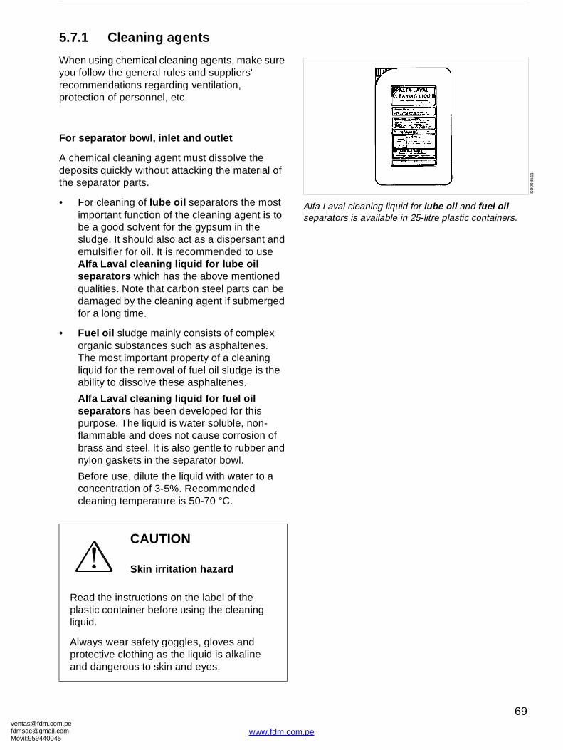
Alfa Laval cleaning liquid for lube oil and fuel oil separators is available in 25-litre plastic containers.
5.7.1 Cleaning agents
When using chemical cleaning agents, make sure you follow the general rules and suppliers' recommendations regarding ventilation, protection of personnel, etc.
For separator b owl, inlet and outlet
A chemical cleaning agent must dissolve the deposits quickly without attacking the material of the separator parts.
• For cleaning of lube oil separators the most important function of the cleaning agent is to be a good solvent for the gypsum in the sludge. It should also act as a dispersant and emulsifier for oil. It is recommended to use Alfa Laval cleaning liquid for lube oil separators which has the above mentioned qualities. Note that carbon steel parts can be damaged by the cleaning agent if submerged for a long time.
• Fuel oil sludge mainly consists of complex organic substances such as asphaltenes. The most important property of a cleaning liquid for the removal of fuel oil sludge is the ability to dissolve these asphaltenes.
Alfa Laval cleaning liquid for fuel oil separators has been developed for this purpose. The liquid is water soluble, non-flammable and does not cause corrosion of brass and steel. It is also gentle to rubber and nylon gaskets in the separator bowl.
Before use, dilute the liquid with water to a concentration of 3-5%. Recommended cleaning temperature is 50-70 °C.
CAUTION
Skin irritation hazard
Read the instructions on the label of the plastic container before using the cleaning liquid.
Always wear safety goggles, gloves and protective clothing as the liquid is alkaline and dangerous to skin and eyes.
om.peil.com45
69
www.fdm.com.pe
ventafdmsaMovil:
G00
658
31
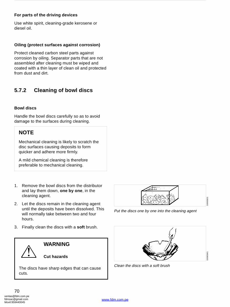
Put the discs one by one into the cleaning agentG
006
584
1
Clean the discs with a soft brush
For parts of the driving devices
Use white spirit, cleaning-grade kerosene or diesel oil.
Oiling (protect surfaces against corrosion)
Protect cleaned carbon steel parts against corrosion by oiling. Separator parts that are not assembled after cleaning must be wiped and coated with a thin layer of clean oil and protected from dust and dirt.
5.7.2 Cleaning of bowl discs
Bowl discs
Handle the bowl discs carefully so as to avoid damage to the surfaces during cleaning.
1. Remove the bowl discs from the distributor and lay them down, one by one , in the cleaning agent.
2. Let the discs remain in the cleaning agent until the deposits have been dissolved. This will normally take between two and four hours.
3. Finally clean the discs with a soft brush.
NOTE
Mechanical cleaning is likely to scratch the disc surfaces causing deposits to form quicker and adhere more firmly.
A mild chemical cleaning is therefore preferable to mechanical cleaning.
WARNING
Cut hazards
The discs have sharp edges that can cause cuts.
[email protected]@gmail.com959440045
70
www.fdm.com.pe
[email protected]@gmaMovil:9594400
G0
0688
11G
006
891
1
5.8 Oil change
5.8.1 Oil change procedure
The separator should be level and at standstill when oil is filled or the oil level is checked. The MIN-line on the sight glass refers to the oil level at standstill.
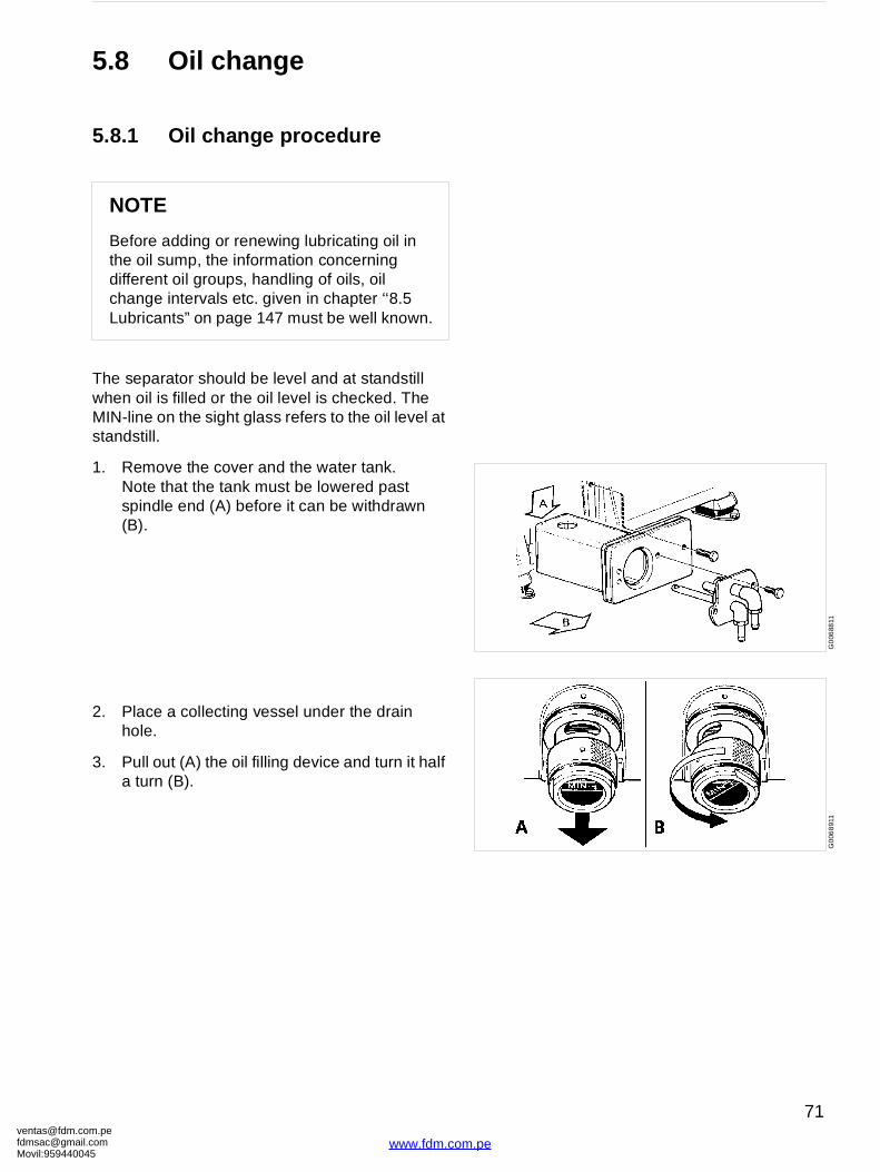
1. Remove the cover and the water tank.Note that the tank must be lowered past spindle end (A) before it can be withdrawn (B).
2. Place a collecting vessel under the drain hole.
3. Pull out (A) the oil filling device and turn it half a turn (B).
NOTE
Before adding or renewing lubricating oil in the oil sump, the information concerning different oil groups, handling of oils, oil change intervals etc. given in chapter ‘‘8.5 Lubricants” on page 147 must be well known.
om.peil.com45
71
www.fdm.com.pe
ventafdmsaMovil:
G01
7381
1G
0069
111
G00
6921
1G
0069
321
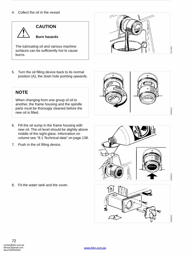
4. Collect the oil in the vessel.
5. Turn the oil filling device back to its normal position (A), the drain hole pointing upwards.
6. Fill the oil sump in the frame housing with new oil. The oil level should be slightly above middle of the sight glass. Information on volume see ‘‘8.1 Technical data” on page 138.
7. Push in the oil filling device.
8. Fit the water tank and the cover.
CAUTION
Burn hazards
The lubricating oil and various machine surfaces can be sufficiently hot to cause burns.
NOTE
When changing from one group of oil to another, the frame housing and the spindle parts must be thorougly cleaned before the new oil is filled.
[email protected]@gmail.com959440045
72
www.fdm.com.pe
[email protected]@gmaMovil:9594400
G00
752
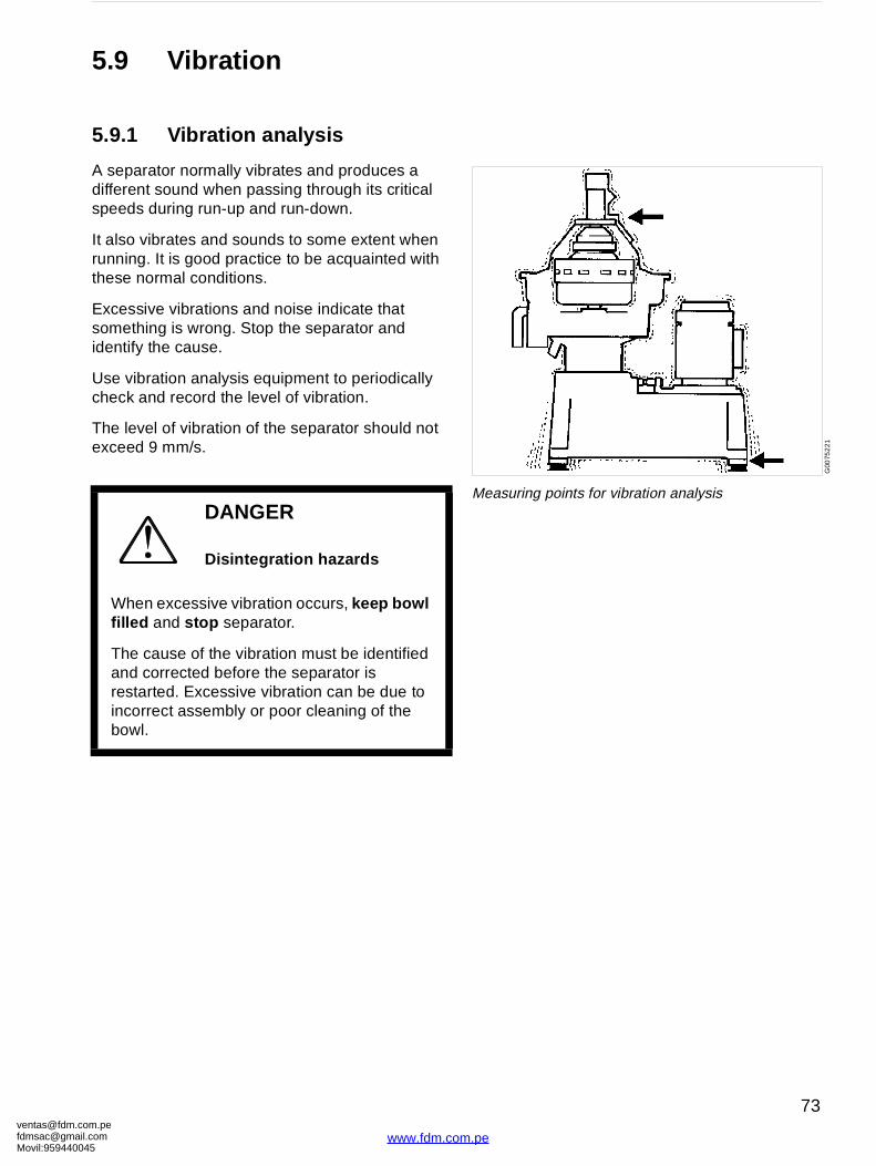
21
Measuring points for vibration analysis
5.9 Vibration
5.9.1 Vibration analysis
A separator normally vibrates and produces a different sound when passing through its critical speeds during run-up and run-down.
It also vibrates and sounds to some extent when running. It is good practice to be acquainted with these normal conditions.
Excessive vibrations and noise indicate that something is wrong. Stop the separator and identify the cause.
Use vibration analysis equipment to periodically check and record the level of vibration.
The level of vibration of the separator should not exceed 9 mm/s.
DANGER
Disintegration hazards
When excessive vibration occurs, keep bowl filled and stop separator.
The cause of the vibration must be identified and corrected before the separator is restarted. Excessive vibration can be due to incorrect assembly or poor cleaning of the bowl.
om.peil.com45
73
www.fdm.com.pe
ventafdmsaMovil:
G0
5873
21
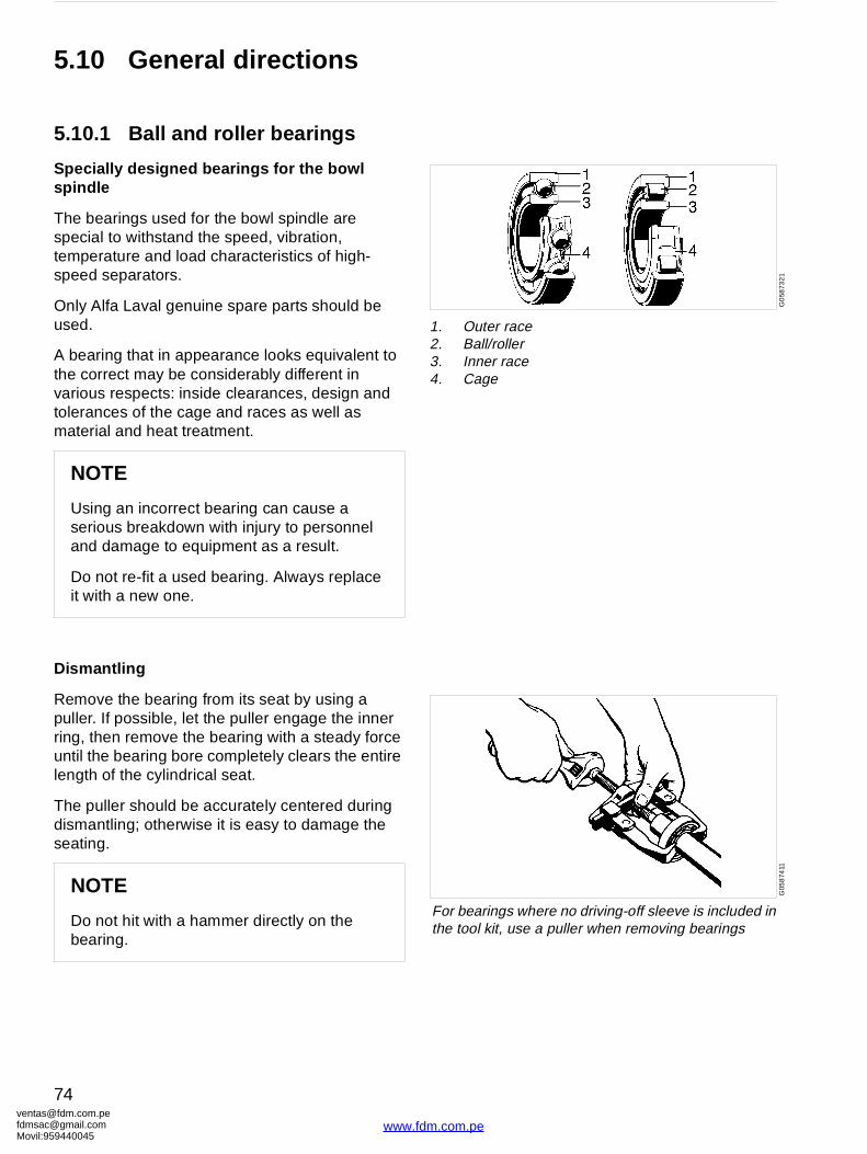
1. Outer race2. Ball/roller3. Inner race4. Cage
G05
874
11
For bearings where no driving-off sleeve is included in the tool kit, use a puller when removing bearings
5.10 General directions
5.10.1 Ball and roller bearings
Specially designed bearings for the bowl spindle
The bearings used for the bowl spindle are special to withstand the speed, vibration, temperature and load characteristics of high-speed separators.
Only Alfa Laval genuine spare parts should be used.
A bearing that in appearance looks equivalent to the correct may be considerably different in various respects: inside clearances, design and tolerances of the cage and races as well as material and heat treatment.
Dismantling
Remove the bearing from its seat by using a puller. If possible, let the puller engage the inner ring, then remove the bearing with a steady force until the bearing bore completely clears the entire length of the cylindrical seat.
The puller should be accurately centered during dismantling; otherwise it is easy to damage the seating.
NOTE
Using an incorrect bearing can cause a serious breakdown with injury to personnel and damage to equipment as a result.
Do not re-fit a used bearing. Always replace it with a new one.
NOTE
Do not hit with a hammer directly on the bearing.
[email protected]@gmail.com959440045
74
www.fdm.com.pe
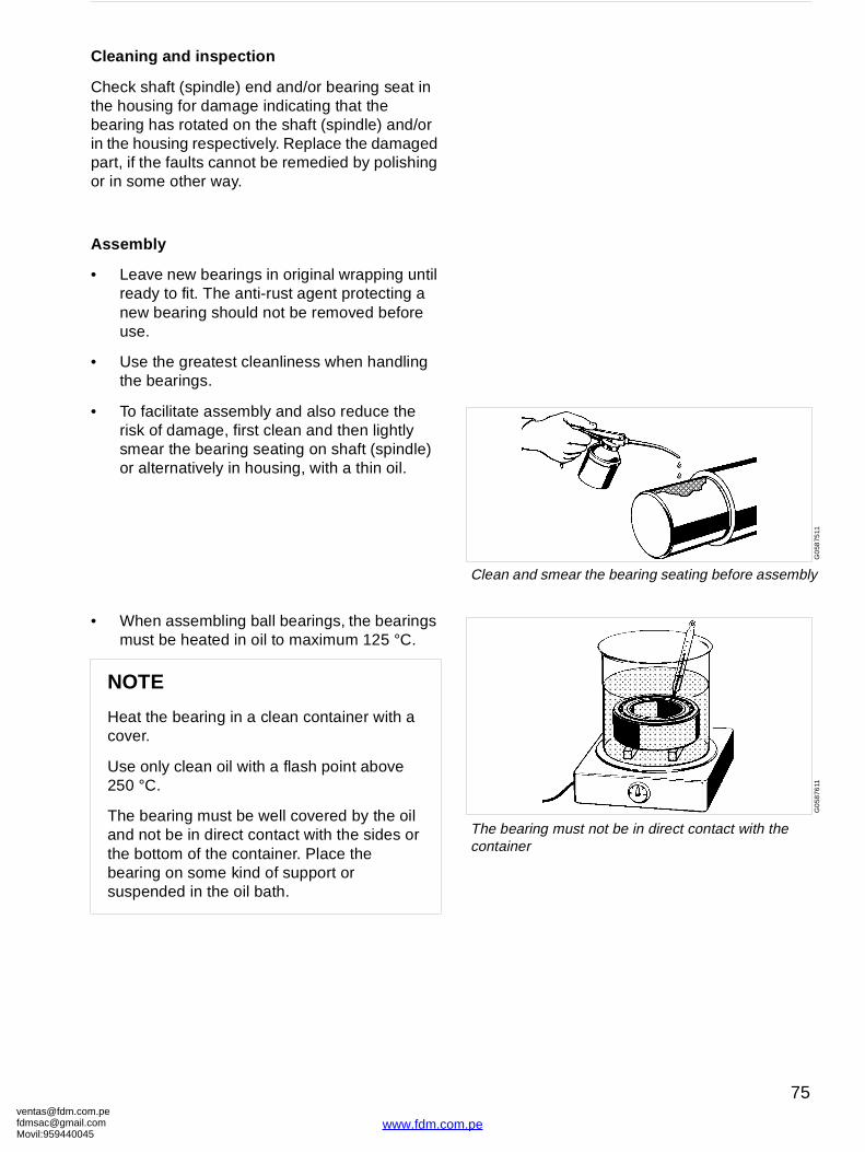
[email protected]@gmaMovil:9594400
G0
5875
11
Clean and smear the bearing seating before assembly
G0
5876
11
The bearing must not be in direct contact with the container
Cleaning and inspection
Check shaft (spindle) end and/or bearing seat in the housing for damage indicating that the bearing has rotated on the shaft (spindle) and/or in the housing respectively. Replace the damaged part, if the faults cannot be remedied by polishing or in some other way.
Assembly
• Leave new bearings in original wrapping until ready to fit. The anti-rust agent protecting a new bearing should not be removed before use.
• Use the greatest cleanliness when handling the bearings.
• To facilitate assembly and also reduce the risk of damage, first clean and then lightly smear the bearing seating on shaft (spindle) or alternatively in housing, with a thin oil.
• When assembling ball bearings, the bearings must be heated in oil to maximum 125 °C.
NOTE
Heat the bearing in a clean container with a cover.
Use only clean oil with a flash point above 250 °C.
The bearing must be well covered by the oil and not be in direct contact with the sides or the bottom of the container. Place the bearing on some kind of support or suspended in the oil bath.
om.peil.com45
75
www.fdm.com.pe
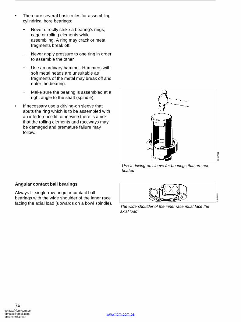
ventafdmsaMovil:
G0
5877
11
Use a driving-on sleeve for bearings that are not heated
G05
8721
1
The wide shoulder of the inner race must face the axial load
• There are several basic rules for assembling cylindrical bore bearings:
− Never directly strike a bearing’s rings, cage or rolling elements while assembling. A ring may crack or metal fragments break off.
− Never apply pressure to one ring in order to assemble the other.
− Use an ordinary hammer. Hammers with soft metal heads are unsuitable as fragments of the metal may break off and enter the bearing.
− Make sure the bearing is assembled at a right angle to the shaft (spindle).
• If necessary use a driving-on sleeve that abuts the ring which is to be assembled with an interference fit, otherwise there is a risk that the rolling elements and raceways may be damaged and premature failure may follow.
Angular contact ball bearings
Always fit single-row angular contact ball bearings with the wide shoulder of the inner race facing the axial load (upwards on a bowl spindle).
[email protected]@gmail.com959440045
76
www.fdm.com.pe
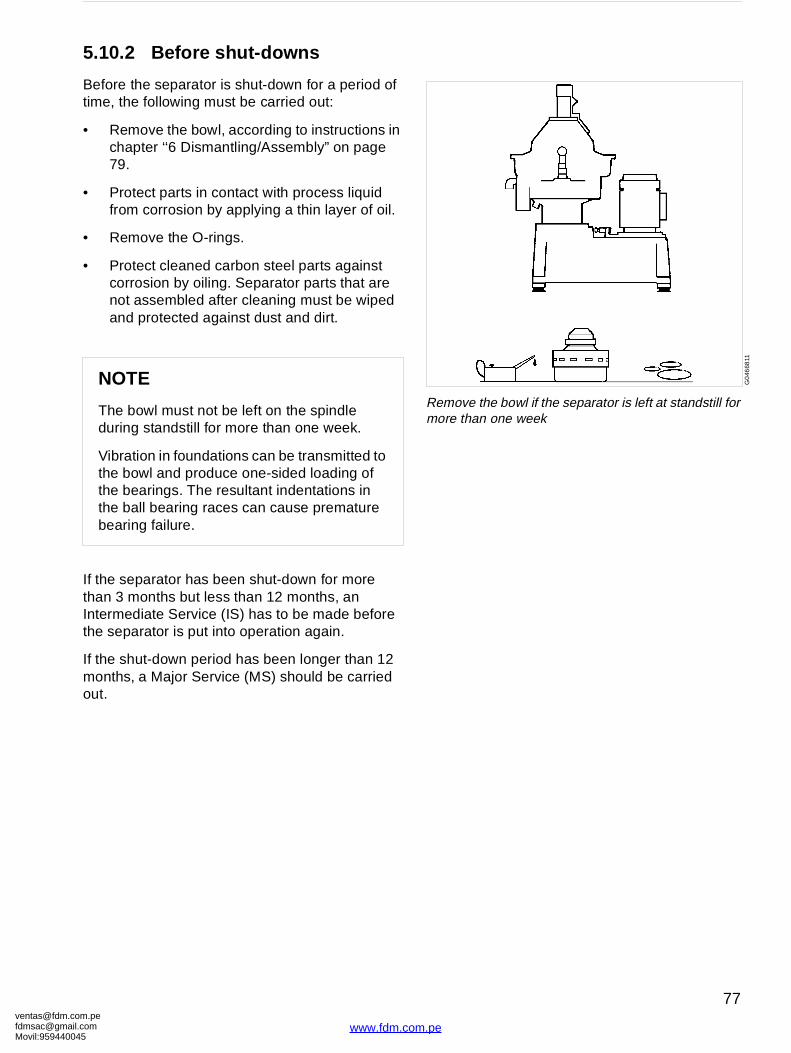
[email protected]@gmaMovil:9594400
G0
4668
11
Remove the bowl if the separator is left at standstill for more than one week
5.10.2 Before shut-downs
Before the separator is shut-down for a period of time, the following must be carried out:
• Remove the bowl, according to instructions in chapter ‘‘6 Dismantling/Assembly” on page 79.
• Protect parts in contact with process liquid from corrosion by applying a thin layer of oil.
• Remove the O-rings.
• Protect cleaned carbon steel parts against corrosion by oiling. Separator parts that are not assembled after cleaning must be wiped and protected against dust and dirt.
If the separator has been shut-down for more than 3 months but less than 12 months, an Intermediate Service (IS) has to be made before the separator is put into operation again.
If the shut-down period has been longer than 12 months, a Major Service (MS) should be carried out.
NOTE
The bowl must not be left on the spindle during standstill for more than one week.
Vibration in foundations can be transmitted to the bowl and produce one-sided loading of the bearings. The resultant indentations in the ball bearing races can cause premature bearing failure.
om.peil.com45
77
www.fdm.com.pe
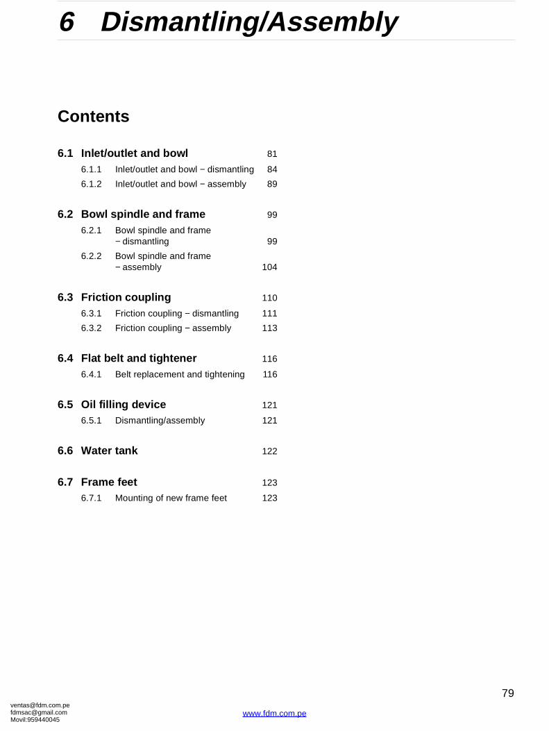
[email protected]@gmaMovil:9594400
6 Dismantling/Assembly
Contents
6.1 Inlet/outlet and bowl 81
6.1.1 Inlet/outlet and bowl − dismantling 84
6.1.2 Inlet/outlet and bowl − assembly 89
6.2 Bowl spindle and frame 99
6.2.1 Bowl spindle and frame − dismantling 99
6.2.2 Bowl spindle and frame − assembly 104
6.3 Friction coupling 110
6.3.1 Friction coupling − dismantling 111
6.3.2 Friction coupling − assembly 113
6.4 Flat belt and tightener 116
6.4.1 Belt replacement and tightening 116
6.5 Oil filling device 121
6.5.1 Dismantling/assembly 121
6.6 Water tank 122
6.7 Frame feet 123
6.7.1 Mounting of new frame feet 123
om.peil.com45
www.fdm.co
79
m.pe
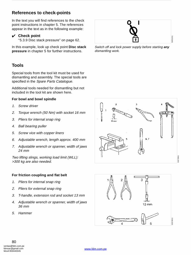
ventafdmsaMovil:
S00
510
11
Switch off and lock power supply before starting any dismantling work.
G02
788
11
G0
5786
11
References to check-points
In the text you will find references to the check point instructions in chapter 5. The references appear in the text as in the following example:
✔ Check point‘‘5.3.9 Disc stack pressure” on page 62.
In this example, look up check point Disc stack pressure in chapter 5 for further instructions.
Tools
Special tools from the tool kit must be used for dismantling and assembly. The special tools are specified in the Spare Parts Catalogue.
Additional tools needed for dismantling but not included in the tool kit are shown here.
For bowl and bowl spindle
1. Screw driver
2. Torque wrench (50 Nm) with socket 16 mm
3. Pliers for internal snap ring
4. Ball bearing puller
5. Screw vice with copper liners
6. Adjustable wrench, length approx. 400 mm
7. Adjustable wrench or spanner, width of jaws 24 mm
Two lifting slings, working load limit (WLL): >300 kg are also needed.
For friction coupling and flat belt
1. Pliers for internal snap ring
2. Pliers for external snap ring
3. T-handle, extension rod and socket 13 mm
4. Adjustable wrench or spanner, width of jaws 36 mm
5. Hammer
[email protected]@gmail.com959440045
80
www.fdm.com.pe
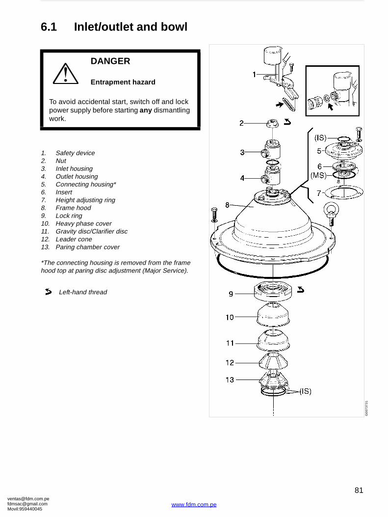
[email protected]@gmaMovil:9594400
G0
0737
31
6.1 Inlet/outlet and bowl
1. Safety device2. Nut3. Inlet housing4. Outlet housing5. Connecting housing*6. Insert7. Height adjusting ring8. Frame hood9. Lock ring10. Heavy phase cover11. Gravity disc/Clarifier disc12. Leader cone13. Paring chamber cover
*The connecting housing is removed from the frame hood top at paring disc adjustment (Major Service).
DANGER
Entrapment hazard
To avoid accidental start, switch off and lock power supply before starting any dismantling work.
Left-hand thread
om.peil.com45
81
www.fdm.com.pe

ventafdmsaMovil:
G0
0738
21
14. Inlet pipe15. Bowl hood16. Top disc17. Bowl discs18. Wing insert19. Bowl discs20. Distributor21. Sliding bowl bottom
IS Intermediate service kit MS Major service kit
Left-hand thread
[email protected]@gmail.com959440045
82
www.fdm.com.pe
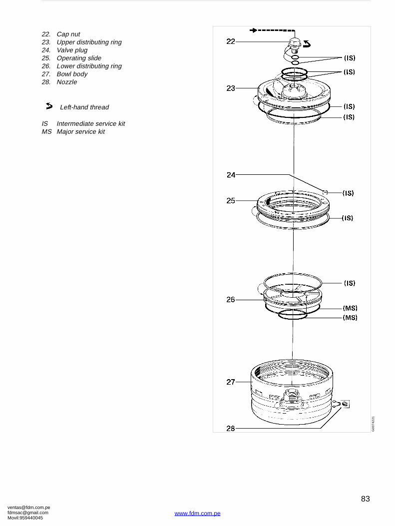
[email protected]@gmaMovil:9594400
G0
0742
21
22. Cap nut23. Upper distributing ring24. Valve plug25. Operating slide26. Lower distributing ring27. Bowl body28. Nozzle
IS Intermediate service kitMS Major service kit
Left-hand thread
om.peil.com45
83
www.fdm.com.pe
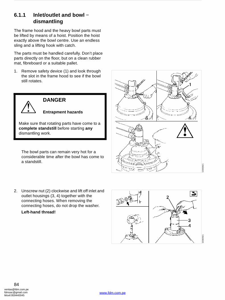
ventafdmsaMovil:
G00
6982
1G
006
992
1
6.1.1 Inlet/outlet and bowl − dismantling
The frame hood and the heavy bowl parts must be lifted by means of a hoist. Position the hoist exactly above the bowl centre. Use an endless sling and a lifting hook with catch.
The parts must be handled carefully. Don’t place parts directly on the floor, but on a clean rubber mat, fibreboard or a suitable pallet.
1. Remove safety device (1) and look through the slot in the frame hood to see if the bowl still rotates.
The bowl parts can remain very hot for a considerable time after the bowl has come to a standstill.
2. Unscrew nut (2) clockwise and lift off inlet and outlet housings (3, 4) together with the connecting hoses. When removing the connecting hoses, do not drop the washer.
Left-hand thread!
DANGER
Entrapment hazards
Make sure that rotating parts have come to a complete standstill before starting any dismantling work.
[email protected]@gmail.com959440045
84
www.fdm.com.pe
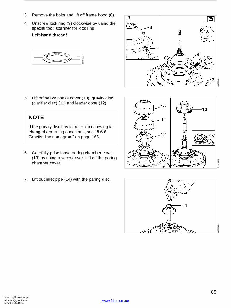
[email protected]@gmaMovil:9594400
G0
070
021
G0
0701
21
G00
7022
1
3. Remove the bolts and lift off frame hood (8).
4. Unscrew lock ring (9) clockwise by using the special tool; spanner for lock ring.
Left-hand thread!
5. Lift off heavy phase cover (10), gravity disc (clarifier disc) (11) and leader cone (12).
6. Carefully prise loose paring chamber cover (13) by using a screwdriver. Lift off the paring chamber cover.
7. Lift out inlet pipe (14) with the paring disc.
NOTE
If the gravity disc has to be replaced owing to changed operating conditions, see ‘‘8.6.6 Gravity disc nomogram” on page 166.
S0
0961
11
om.peil.com45
85
www.fdm.com.pe
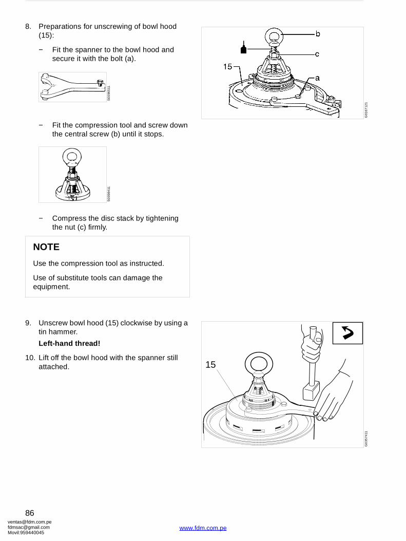
ventafdmsaMovil:
G01
6712
115
G0
3574
11
8. Preparations for unscrewing of bowl hood (15):
− Fit the spanner to the bowl hood and secure it with the bolt (a).
− Fit the compression tool and screw down the central screw (b) until it stops.
− Compress the disc stack by tightening the nut (c) firmly.
9. Unscrew bowl hood (15) clockwise by using a tin hammer.
Left-hand thread!
10. Lift off the bowl hood with the spanner still attached.
NOTE
Use the compression tool as instructed.
Use of substitute tools can damage the equipment.
S0
096
511
S0
0984
11
[email protected]@gmail.com959440045
86
www.fdm.com.pe
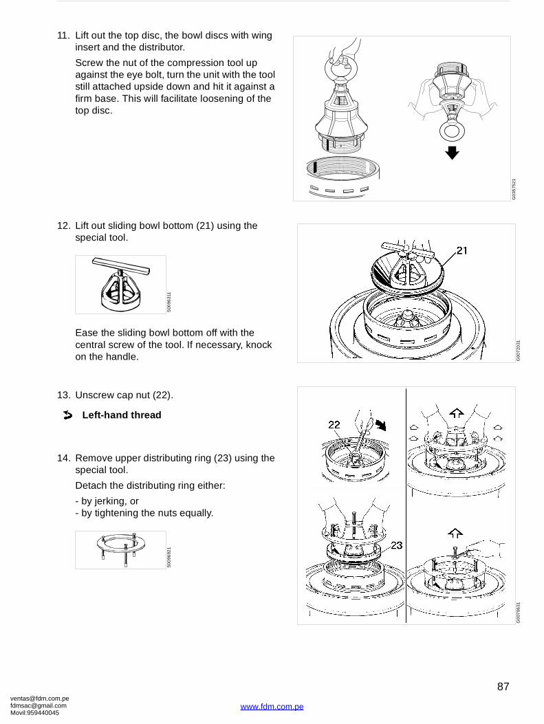
[email protected]@gmaMovil:9594400
G0
3575
21G
007
2031
G0
0706
31
11. Lift out the top disc, the bowl discs with wing insert and the distributor.
Screw the nut of the compression tool up against the eye bolt, turn the unit with the tool still attached upside down and hit it against a firm base. This will facilitate loosening of the top disc.
12. Lift out sliding bowl bottom (21) using the special tool.
Ease the sliding bowl bottom off with the central screw of the tool. If necessary, knock on the handle.
13. Unscrew cap nut (22).
14. Remove upper distributing ring (23) using the special tool.
Detach the distributing ring either:
- by jerking, or- by tightening the nuts equally.
Left-hand thread
S00
9631
1S
00
9692
1
om.peil.com45
87
www.fdm.com.pe
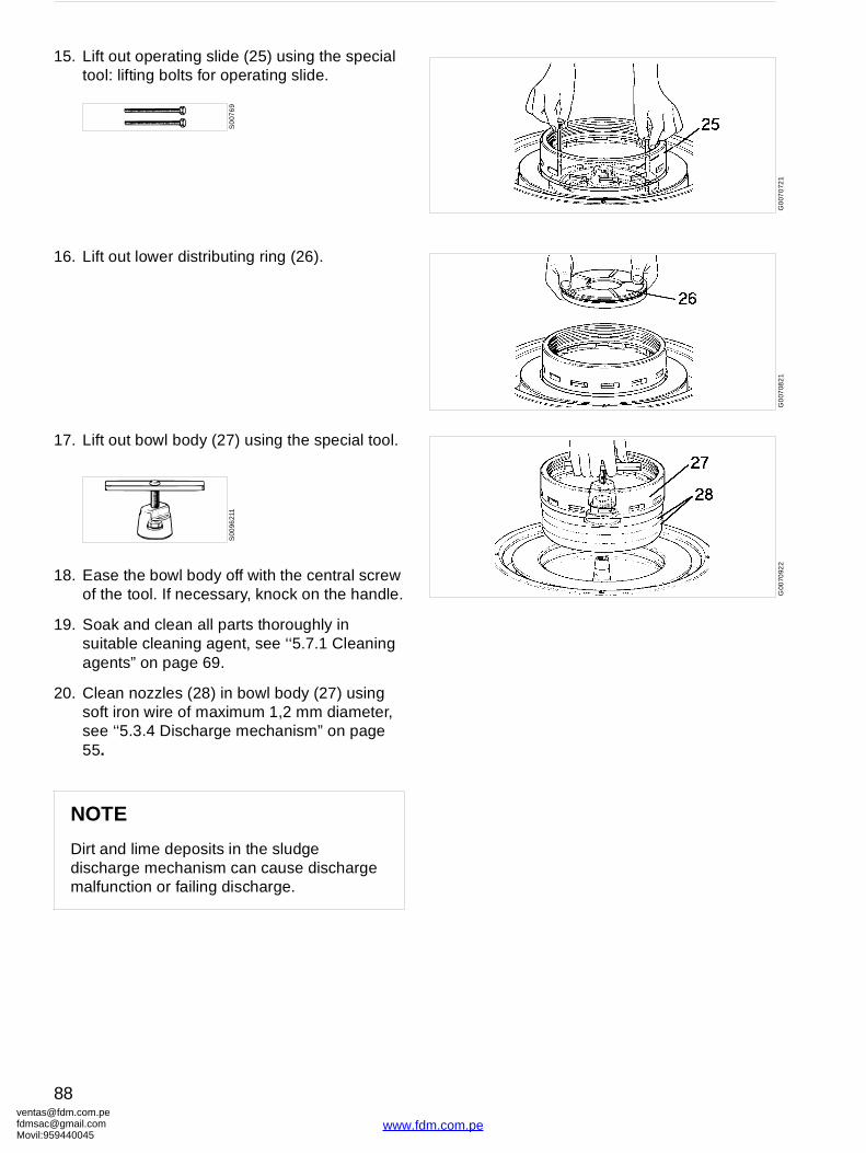
ventafdmsaMovil:
G0
070
721
G0
0708
21
G00
7092
2
15. Lift out operating slide (25) using the special tool: lifting bolts for operating slide.
16. Lift out lower distributing ring (26).
17. Lift out bowl body (27) using the special tool.
18. Ease the bowl body off with the central screw of the tool. If necessary, knock on the handle.
19. Soak and clean all parts thoroughly in suitable cleaning agent, see ‘‘5.7.1 Cleaning agents” on page 69.
20. Clean nozzles (28) in bowl body (27) using soft iron wire of maximum 1,2 mm diameter, see ‘‘5.3.4 Discharge mechanism” on page 55.
NOTE
Dirt and lime deposits in the sludge discharge mechanism can cause discharge malfunction or failing discharge.
S0
076
91S
0096
211
[email protected]@gmail.com959440045
88
www.fdm.com.pe
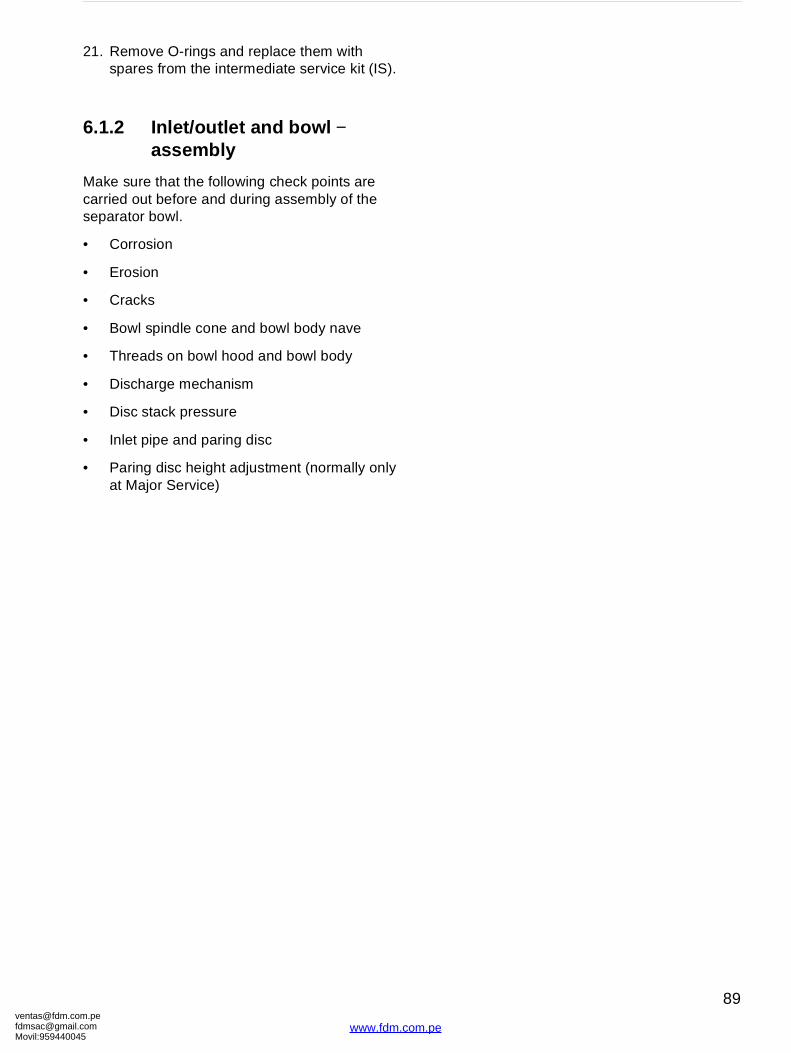
[email protected]@gmaMovil:9594400
21. Remove O-rings and replace them with spares from the intermediate service kit (IS).
6.1.2 Inlet/outlet and bowl − assembly
Make sure that the following check points are carried out before and during assembly of the separator bowl.
• Corrosion
• Erosion
• Cracks
• Bowl spindle cone and bowl body nave
• Threads on bowl hood and bowl body
• Discharge mechanism
• Disc stack pressure
• Inlet pipe and paring disc
• Paring disc height adjustment (normally only at Major Service)
om.peil.com45
89
www.fdm.com.pe
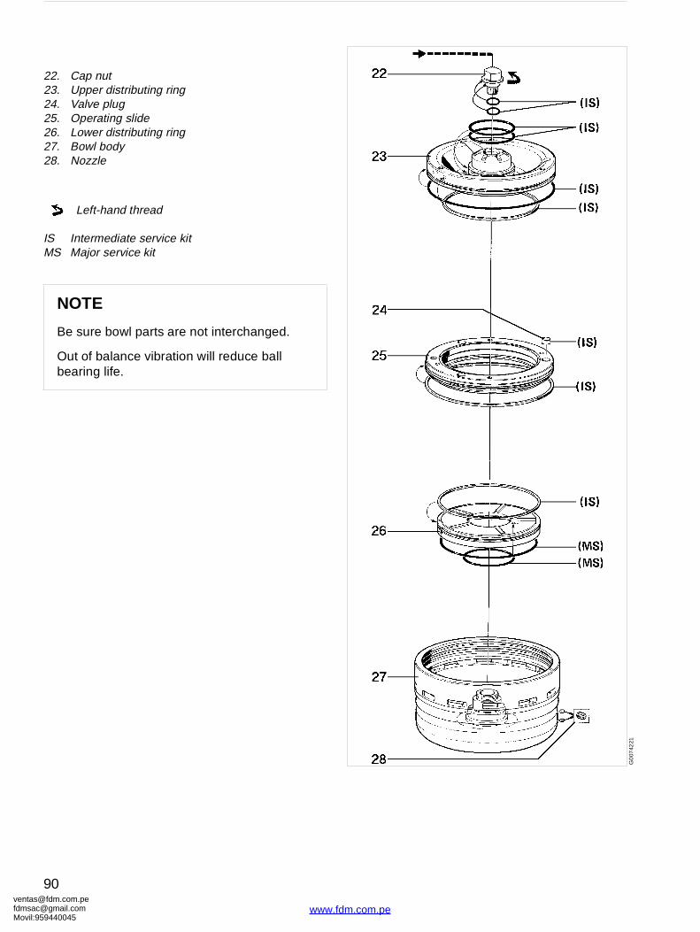
ventafdmsaMovil:
G0
0742
21
22. Cap nut23. Upper distributing ring24. Valve plug25. Operating slide26. Lower distributing ring27. Bowl body28. Nozzle
IS Intermediate service kitMS Major service kit
Left-hand thread
NOTE
Be sure bowl parts are not interchanged.
Out of balance vibration will reduce ball bearing life.
[email protected]@gmail.com959440045
90
www.fdm.com.pe
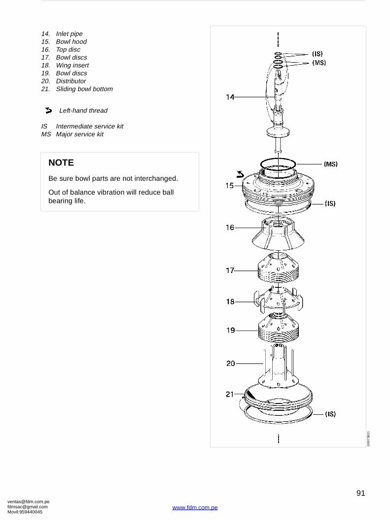
[email protected]@gmaMovil:9594400
G0
0738
21
14. Inlet pipe15. Bowl hood16. Top disc17. Bowl discs18. Wing insert19. Bowl discs20. Distributor21. Sliding bowl bottom
IS Intermediate service kitMS Major service kit
Left-hand thread
NOTE
Be sure bowl parts are not interchanged.
Out of balance vibration will reduce ball bearing life.
om.peil.com45
91
www.fdm.com.pe
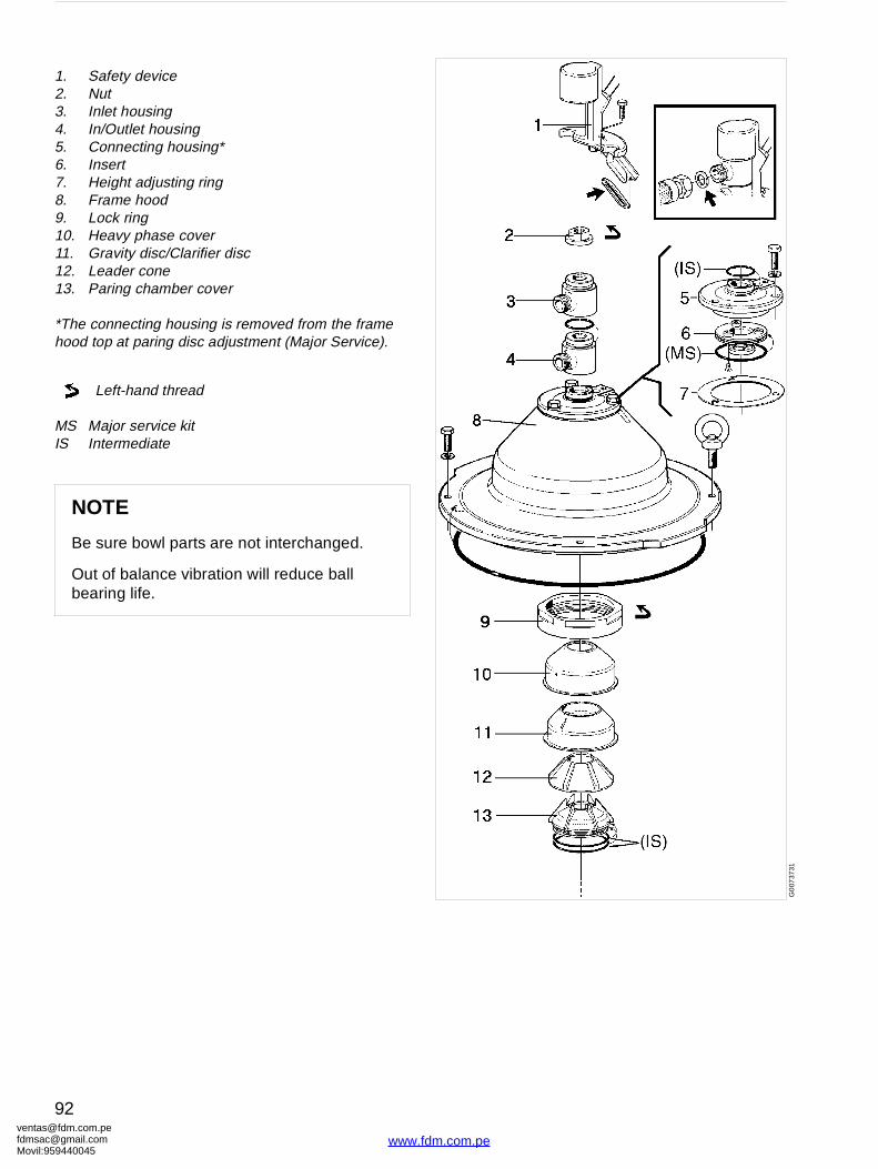
ventafdmsaMovil:
G0
0737
31
1. Safety device2. Nut3. Inlet housing4. In/Outlet housing5. Connecting housing*6. Insert7. Height adjusting ring8. Frame hood9. Lock ring10. Heavy phase cover11. Gravity disc/Clarifier disc12. Leader cone13. Paring chamber cover
*The connecting housing is removed from the frame hood top at paring disc adjustment (Major Service).
MS Major service kitIS Intermediate
Left-hand thread
NOTE
Be sure bowl parts are not interchanged.
Out of balance vibration will reduce ball bearing life.
[email protected]@gmail.com959440045
92
www.fdm.com.pe
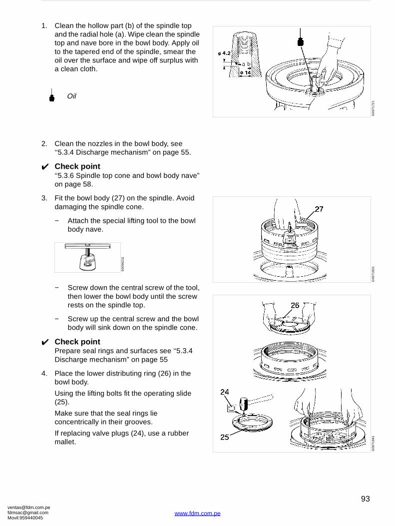
[email protected]@gmaMovil:9594400
G0
071
721
G00
7183
1G
0071
841
1. Clean the hollow part (b) of the spindle top and the radial hole (a). Wipe clean the spindle top and nave bore in the bowl body. Apply oil to the tapered end of the spindle, smear the oil over the surface and wipe off surplus with a clean cloth.
2. Clean the nozzles in the bowl body, see ‘‘5.3.4 Discharge mechanism” on page 55.
✔ Check point‘‘5.3.6 Spindle top cone and bowl body nave” on page 58.
3. Fit the bowl body (27) on the spindle. Avoid damaging the spindle cone.
− Attach the special lifting tool to the bowl body nave.
− Screw down the central screw of the tool, then lower the bowl body until the screw rests on the spindle top.
− Screw up the central screw and the bowl body will sink down on the spindle cone.
✔ Check pointPrepare seal rings and surfaces see ‘‘5.3.4 Discharge mechanism” on page 55
4. Place the lower distributing ring (26) in the bowl body.
Using the lifting bolts fit the operating slide (25).
Make sure that the seal rings lie concentrically in their grooves.
If replacing valve plugs (24), use a rubber mallet.
Oil
S00
962
11
om.peil.com45
93
www.fdm.com.pe
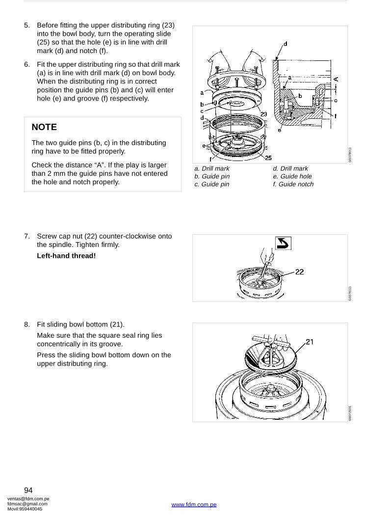
ventafdmsaMovil:
G0
3780
11
a. Drill mark b. Guide pinc. Guide pin
d. Drill mark e. Guide holef. Guide notch
G03
7811
1G
007
2031
5. Before fitting the upper distributing ring (23) into the bowl body, turn the operating slide (25) so that the hole (e) is in line with drill mark (d) and notch (f).
6. Fit the upper distributing ring so that drill mark (a) is in line with drill mark (d) on bowl body. When the distributing ring is in correct position the guide pins (b) and (c) will enter hole (e) and groove (f) respectively.
7. Screw cap nut (22) counter-clockwise onto the spindle. Tighten firmly.
Left-hand thread!
8. Fit sliding bowl bottom (21).
Make sure that the square seal ring lies concentrically in its groove.
Press the sliding bowl bottom down on the upper distributing ring.
NOTE
The two guide pins (b, c) in the distributing ring have to be fitted properly.
Check the distance “A”. If the play is larger than 2 mm the guide pins have not entered the hole and notch properly.
[email protected]@gmail.com959440045
94
www.fdm.com.pe
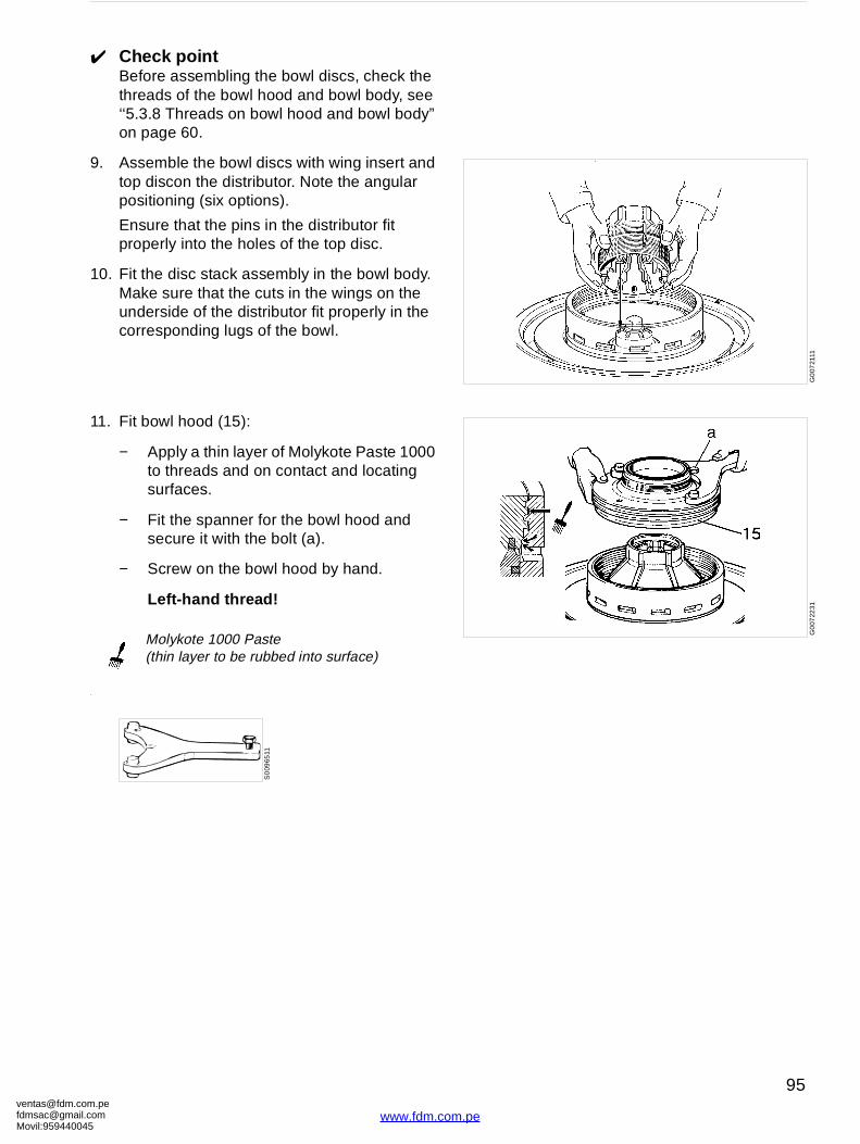
[email protected]@gmaMovil:9594400
G0
0721
11G
007
2231
✔ Check pointBefore assembling the bowl discs, check the threads of the bowl hood and bowl body, see ‘‘5.3.8 Threads on bowl hood and bowl body” on page 60.
9. Assemble the bowl discs with wing insert and top discon the distributor. Note the angular positioning (six options).
Ensure that the pins in the distributor fit properly into the holes of the top disc.
10. Fit the disc stack assembly in the bowl body. Make sure that the cuts in the wings on the underside of the distributor fit properly in the corresponding lugs of the bowl.
11. Fit bowl hood (15):
− Apply a thin layer of Molykote Paste 1000 to threads and on contact and locating surfaces.
− Fit the spanner for the bowl hood and secure it with the bolt (a).
− Screw on the bowl hood by hand.
Left-hand thread!
.
Molykote 1000 Paste (thin layer to be rubbed into surface)
S0
0965
11
om.peil.com45
95
www.fdm.com.pe
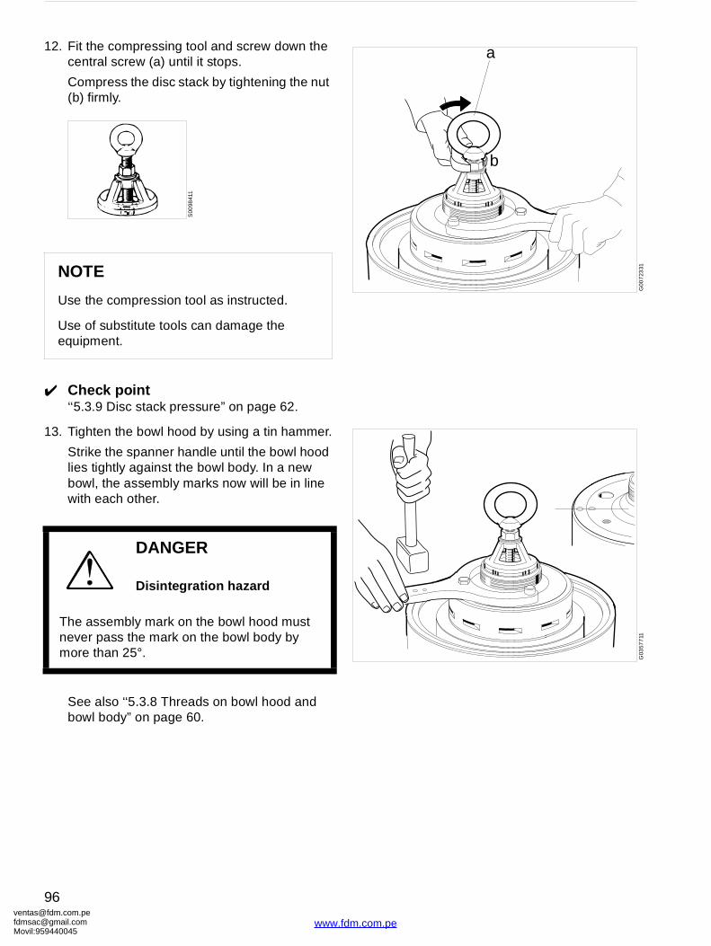
ventafdmsaMovil:
a
b
G00
723
31G
0357
711
12. Fit the compressing tool and screw down the central screw (a) until it stops.
Compress the disc stack by tightening the nut (b) firmly.
✔ Check point‘‘5.3.9 Disc stack pressure” on page 62.
13. Tighten the bowl hood by using a tin hammer.
Strike the spanner handle until the bowl hood lies tightly against the bowl body. In a new bowl, the assembly marks now will be in line with each other.
See also ‘‘5.3.8 Threads on bowl hood and bowl body” on page 60.
NOTE
Use the compression tool as instructed.
Use of substitute tools can damage the equipment.
DANGER
Disintegration hazard
The assembly mark on the bowl hood must never pass the mark on the bowl body by more than 25°.
S00
9841
1
[email protected]@gmail.com959440045
96
www.fdm.com.pe
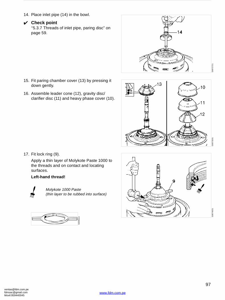
[email protected]@gmaMovil:9594400
G00
7272
1G
007
3331
G00
743
21
14. Place inlet pipe (14) in the bowl.
✔ Check point‘‘5.3.7 Threads of inlet pipe, paring disc” on page 59.
15. Fit paring chamber cover (13) by pressing it down gently.
16. Assemble leader cone (12), gravity disc/ clarifier disc (11) and heavy phase cover (10).
17. Fit lock ring (9).
Apply a thin layer of Molykote Paste 1000 to the threads and on contact and locating surfaces.
Left-hand thread!
Molykote 1000 Paste (thin layer to be rubbed into surface)
S00
961
11
om.peil.com45
97
www.fdm.com.pe
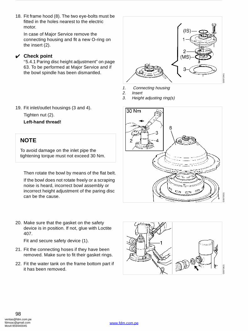
ventafdmsaMovil:
G0
072
941
1. Connecting housing2. Insert3. Height adjusting ring(s)
G00
7353
1G
007
3621
18. Fit frame hood (8). The two eye-bolts must be fitted in the holes nearest to the electric motor.
In case of Major Service remove the connecting housing and fit a new O-ring on the insert (2).
✔ Check point‘‘5.4.1 Paring disc height adjustment” on page 63. To be performed at Major Service and if the bowl spindle has been dismantled.
19. Fit inlet/outlet housings (3 and 4).
Tighten nut (2).
Left-hand thread!
Then rotate the bowl by means of the flat belt.
If the bowl does not rotate freely or a scraping noise is heard, incorrect bowl assembly or incorrect height adjustment of the paring disc can be the cause.
20. Make sure that the gasket on the safety device is in position. If not, glue with Loctite 407.
Fit and secure safety device (1).
21. Fit the connecting hoses if they have been removed. Make sure to fit their gasket rings.
22. Fit the water tank on the frame bottom part if it has been removed.
NOTE
To avoid damage on the inlet pipe the tightening torque must not exceed 30 Nm.
[email protected]@gmail.com959440045
98
www.fdm.com.pe

[email protected]@gmaMovil:9594400
G01
131
41
G0
1132
31
6.2 Bowl spindle and frame
6.2.1 Bowl spindle and frame − dismantling
Before dismantling the bowl spindle, the inlet and outlet housings, frame hood and bowl as well as the flat belt must be removed.
Before dismantling, in the case of Major Service, or if the separator vibrates while running, see
✔ Check point‘‘5.4.2 Radial wobble of bowl spindle” on page 64.
MS Parts to be renewed at Major Service
1. Lip seal ring2. Screen3. Gasket4. Frame, top part5. Deflector ring6. Top bearing cover7. Gasket8. Fan9. Buffer holder10. Rubber buffer11. Bowl spindle
12. Ball bearing holder13. Ball bearing14. Snap ring15. Ball bearing16. Oil pump17. Belt pulley18. Pump sleeve19. Rubber buffer20. O-ring21. Frame, intermediate22. O-ring
om.peil.com45
99
www.fdm.com.pe
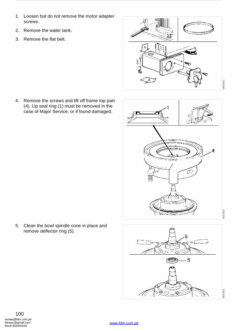
ventafdmsaMovil:
G01
133
21G
011
343
1G
011
352
1
1. Loosen but do not remove the motor adapter screws.
2. Remove the water tank.
3. Remove the flat belt.
4. Remove the screws and lift off frame top part (4). Lip seal ring (1) must be removed in the case of Major Service, or if found damaged.
5. Clean the bowl spindle cone in place and remove deflector ring (5).
[email protected]@gmail.com959440045
100
www.fdm.com.pe
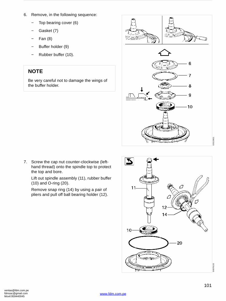
[email protected]@gmaMovil:9594400
G01
136
21G
0076
132
6. Remove, in the following sequence:
− Top bearing cover (6)
− Gasket (7)
− Fan (8)
− Buffer holder (9)
− Rubber buffer (10).
7. Screw the cap nut counter-clockwise (left-hand thread) onto the spindle top to protect the top and bore.
Lift out spindle assembly (11), rubber buffer (10) and O-ring (20).
Remove snap ring (14) by using a pair of pliers and pull off ball bearing holder (12).
NOTE
Be very careful not to damage the wings of the buffer holder.
om.peil.com45
101
www.fdm.com.pe
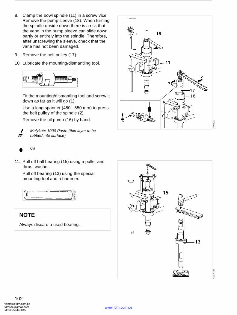
ventafdmsaMovil:
G00
7622
1G
00
7632
1
8. Clamp the bowl spindle (11) in a screw vice. Remove the pump sleeve (18). When turning the spindle upside down there is a risk that the vane in the pump sleeve can slide down partly or entirely into the spindle. Therefore, after unscrewing the sleeve, check that the vane has not been damaged.
9. Remove the belt pulley (17):
10. Lubricate the mounting/dismantling tool.
Fit the mounting/dismantling tool and screw it down as far as it will go (1).
Use a long spanner (450 - 650 mm) to press the belt pulley of the spindle (2).
Remove the oil pump (16) by hand.
11. Pull off ball bearing (15) using a puller and thrust washer.
Pull off bearing (13) using the special mounting tool and a hammer.
Molykote 1000 Paste (thin layer to be rubbed into surface)
Oil
NOTE
Always discard a used bearing.
S0
0964
11
S0
0937
11
[email protected]@gmail.com959440045
102
www.fdm.com.pe
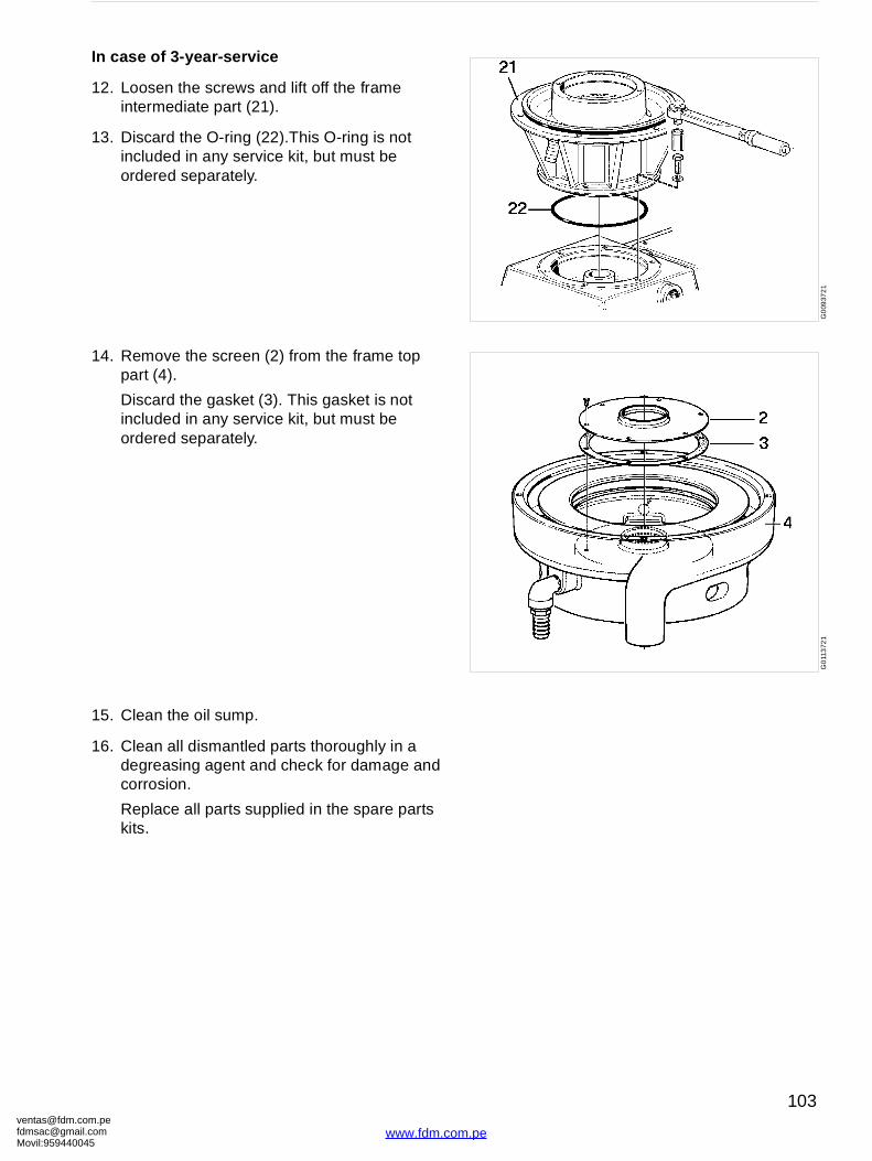
[email protected]@gmaMovil:9594400
G0
0937
21
G0
113
721
In case of 3-year-service
12. Loosen the screws and lift off the frame intermediate part (21).
13. Discard the O-ring (22).This O-ring is not included in any service kit, but must be ordered separately.
14. Remove the screen (2) from the frame top part (4).
Discard the gasket (3). This gasket is not included in any service kit, but must be ordered separately.
15. Clean the oil sump.
16. Clean all dismantled parts thoroughly in a degreasing agent and check for damage and corrosion.
Replace all parts supplied in the spare parts kits.
om.peil.com45
103
www.fdm.com.pe

ventafdmsaMovil:
G01
131
51
6.2.2 Bowl spindle and frame − assembly
The bowl spindle and frame is assembled in reverse sequence to dismantling.
1. Lip seal ring2. Screen3. Gasket4. Frame, top part5. Deflector ring6. Top bearing cover7. Gasket8. Fan 9. Buffer holder10. Rubber buffer11. Bowl spindle12. Ball bearing holder
13. Ball bearing14. Snap ring15. Ball bearing16. Oil pump17. Belt pulley18. Pump sleeve19. Rubber buffer20. O-ring21. Frame, intermediate
part22. O-ring
MS Major service kit
Loctite 242
Silicone grease (thin layer)
Molykote 1000 Paste (thin layer to be rubbed into surface)
G0
113
231
[email protected]@gmail.com959440045
104
www.fdm.com.pe
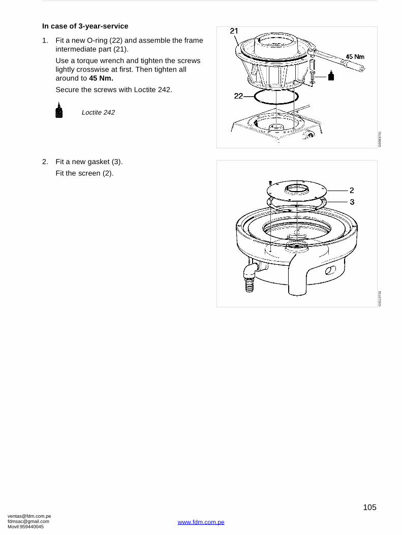
[email protected]@gmaMovil:9594400
G0
0937
31
G01
137
31
In case of 3-year-service
1. Fit a new O-ring (22) and assemble the frame intermediate part (21).
Use a torque wrench and tighten the screws lightly crosswise at first. Then tighten all around to 45 Nm.
Secure the screws with Loctite 242.
2. Fit a new gasket (3).
Fit the screen (2).
Loctite 242
om.peil.com45
105
www.fdm.com.pe
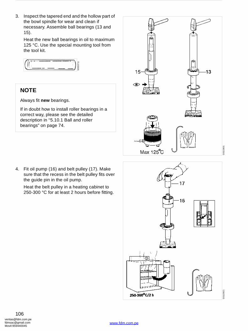
ventafdmsaMovil:
G01
138
31G
0113
921
3. Inspect the tapered end and the hollow part of the bowl spindle for wear and clean if necessary. Assemble ball bearings (13 and 15).
Heat the new ball bearings in oil to maximum 125 °C. Use the special mounting tool from the tool kit.
4. Fit oil pump (16) and belt pulley (17). Make sure that the recess in the belt pulley fits over the guide pin in the oil pump.
Heat the belt pulley in a heating cabinet to 250-300 °C for at least 2 hours before fitting.
NOTE
Always fit new bearings.
If in doubt how to install roller bearings in a correct way, please see the detailed description in ‘‘5.10.1 Ball and roller bearings” on page 74.
S00
937
11
[email protected]@gmail.com959440045
106
www.fdm.com.pe
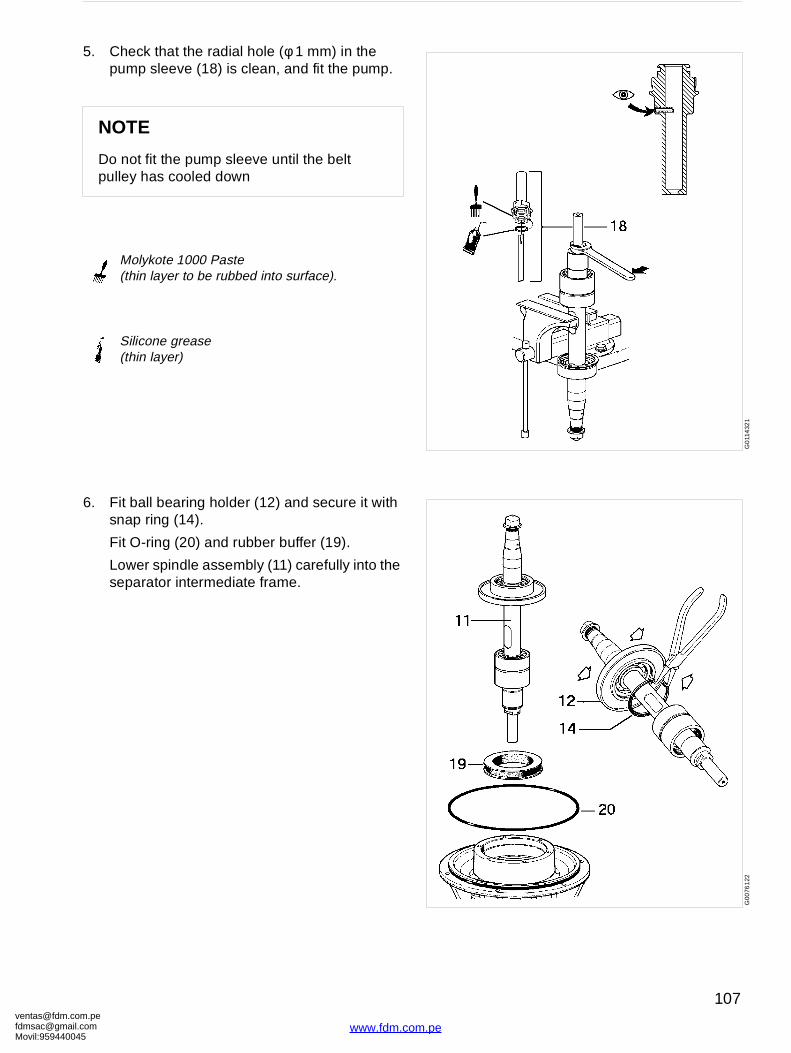
[email protected]@gmaMovil:9594400
G0
114
321
G00
761
22
5. Check that the radial hole (φ 1 mm) in the pump sleeve (18) is clean, and fit the pump.
6. Fit ball bearing holder (12) and secure it with snap ring (14).
Fit O-ring (20) and rubber buffer (19).
Lower spindle assembly (11) carefully into the separator intermediate frame.
NOTE
Do not fit the pump sleeve until the belt pulley has cooled down
Molykote 1000 Paste(thin layer to be rubbed into surface).
Silicone grease(thin layer)
om.peil.com45
107
www.fdm.com.pe
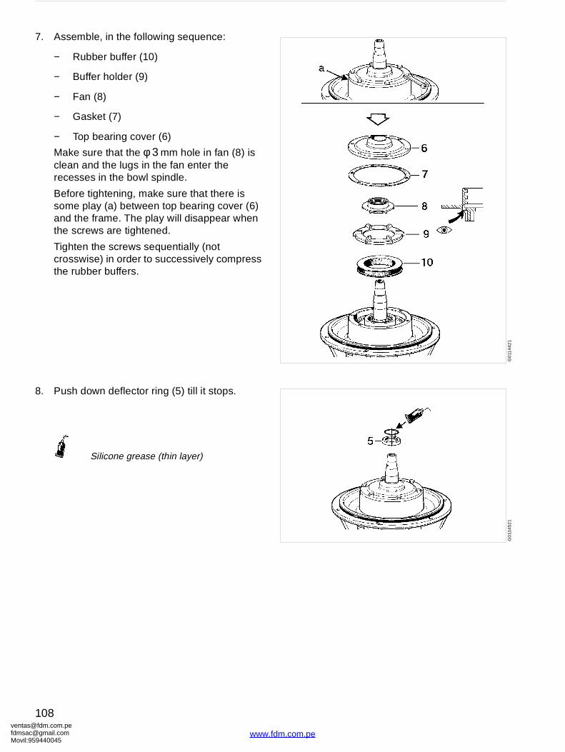
ventafdmsaMovil:
G0
1144
21
G0
114
521
7. Assemble, in the following sequence:
− Rubber buffer (10)
− Buffer holder (9)
− Fan (8)
− Gasket (7)
− Top bearing cover (6)
Make sure that the φ 3 mm hole in fan (8) is clean and the lugs in the fan enter the recesses in the bowl spindle.
Before tightening, make sure that there is some play (a) between top bearing cover (6) and the frame. The play will disappear when the screws are tightened.
Tighten the screws sequentially (not crosswise) in order to successively compress the rubber buffers.
8. Push down deflector ring (5) till it stops.
Silicone grease (thin layer)
[email protected]@gmail.com959440045
108
www.fdm.com.pe
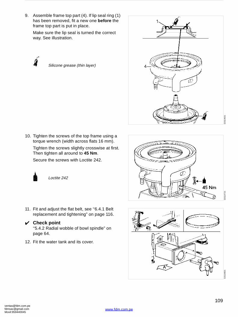
[email protected]@gmaMovil:9594400
G01
146
31G
011
47
21G
0114
821
9. Assemble frame top part (4). If lip seal ring (1) has been removed, fit a new one before the frame top part is put in place.
Make sure the lip seal is turned the correct way. See illustration.
10. Tighten the screws of the top frame using a torque wrench (width across flats 16 mm).
Tighten the screws slightly crosswise at first. Then tighten all around to 45 Nm.
Secure the screws with Loctite 242.
11. Fit and adjust the flat belt, see ‘‘6.4.1 Belt replacement and tightening” on page 116.
✔ Check point‘‘5.4.2 Radial wobble of bowl spindle” on page 64.
12. Fit the water tank and its cover.
Silicone grease (thin layer)
Loctite 242
om.peil.com45
109
www.fdm.com.pe
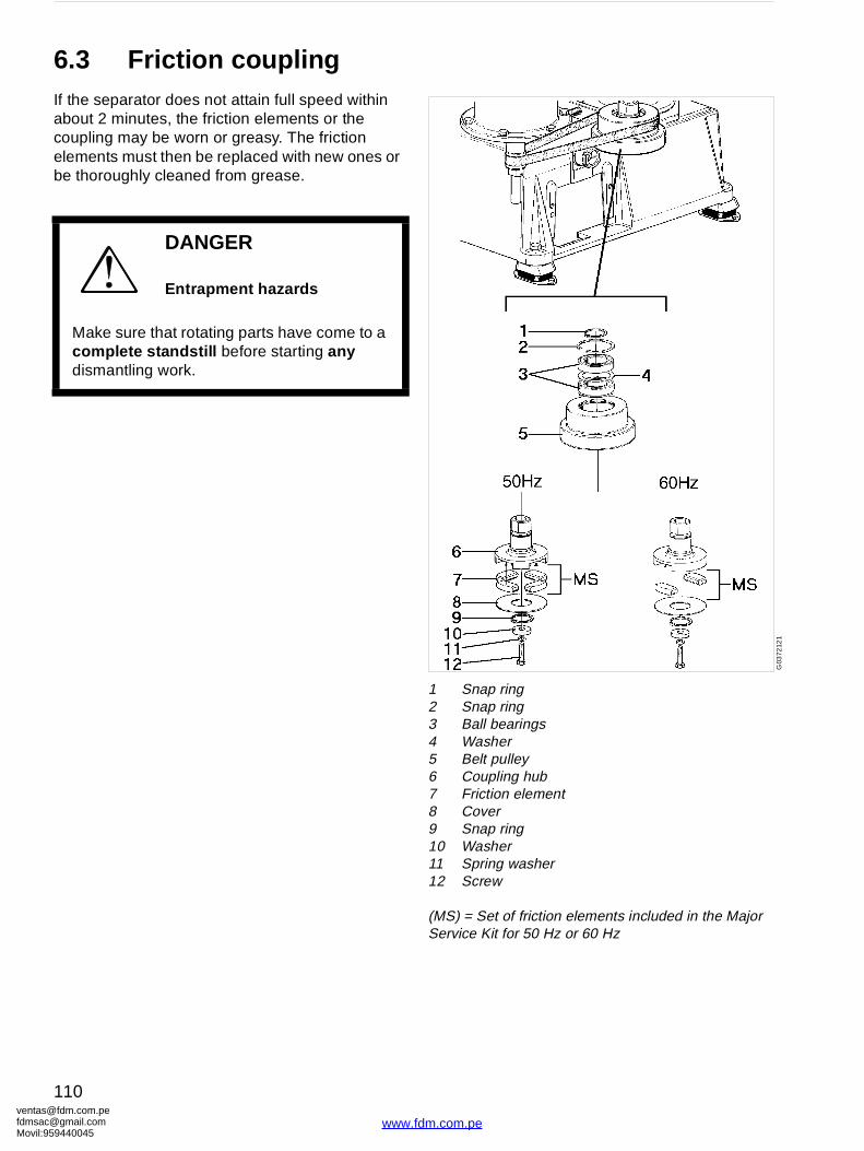
ventafdmsaMovil:
G03
7212
1
1 Snap ring2 Snap ring3 Ball bearings4 Washer5 Belt pulley6 Coupling hub7 Friction element8 Cover9 Snap ring10 Washer11 Spring washer12 Screw
(MS) = Set of friction elements included in the Major Service Kit for 50 Hz or 60 Hz
6.3 Friction couplingIf the separator does not attain full speed within about 2 minutes, the friction elements or the coupling may be worn or greasy. The friction elements must then be replaced with new ones or be thoroughly cleaned from grease.
DANGER
Entrapment hazards
Make sure that rotating parts have come to a complete standstill before starting any dismantling work.
[email protected]@gmail.com959440045
110
www.fdm.com.pe
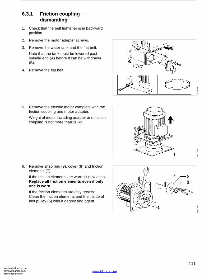
[email protected]@gmaMovil:9594400
G0
119
121
G0
0773
31G
017
084
1
6.3.1 Friction coupling − dismantling
1. Check that the belt tightener is in backward position.
2. Remove the motor adapter screws.
3. Remove the water tank and the flat belt.
Note that the tank must be lowered past spindle end (A) before it can be withdrawn (B).
4. Remove the flat belt.
5. Remove the electric motor complete with the friction coupling and motor adapter.
Weight of motor including adapter and friction coupling is not more than 20 kg.
6. Remove snap ring (9), cover (8) and friction elements (7).
If the friction elements are worn, fit new ones. Replace all friction elements even if only one is worn.
If the friction elements are only greasy:Clean the friction elements and the inside of belt pulley (5) with a degreasing agent.
om.peil.com45
111
www.fdm.com.pe
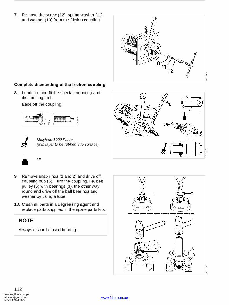
ventafdmsaMovil:
G0
170
921
G01
710
21G
017
1131
7. Remove the screw (12), spring washer (11) and washer (10) from the friction coupling.
Complete dismantling of the friction coupling
8. Lubricate and fit the special mounting and dismantling tool.
Ease off the coupling.
9. Remove snap rings (1 and 2) and drive off coupling hub (6). Turn the coupling, i.e. belt pulley (5) with bearings (3), the other way round and drive off the ball bearings and washer by using a tube.
10. Clean all parts in a degreasing agent and replace parts supplied in the spare parts kits.
Molykote 1000 Paste(thin layer to be rubbed into surface)
Oil
NOTE
Always discard a used bearing.
S00
9641
1
[email protected]@gmail.com959440045
112
www.fdm.com.pe
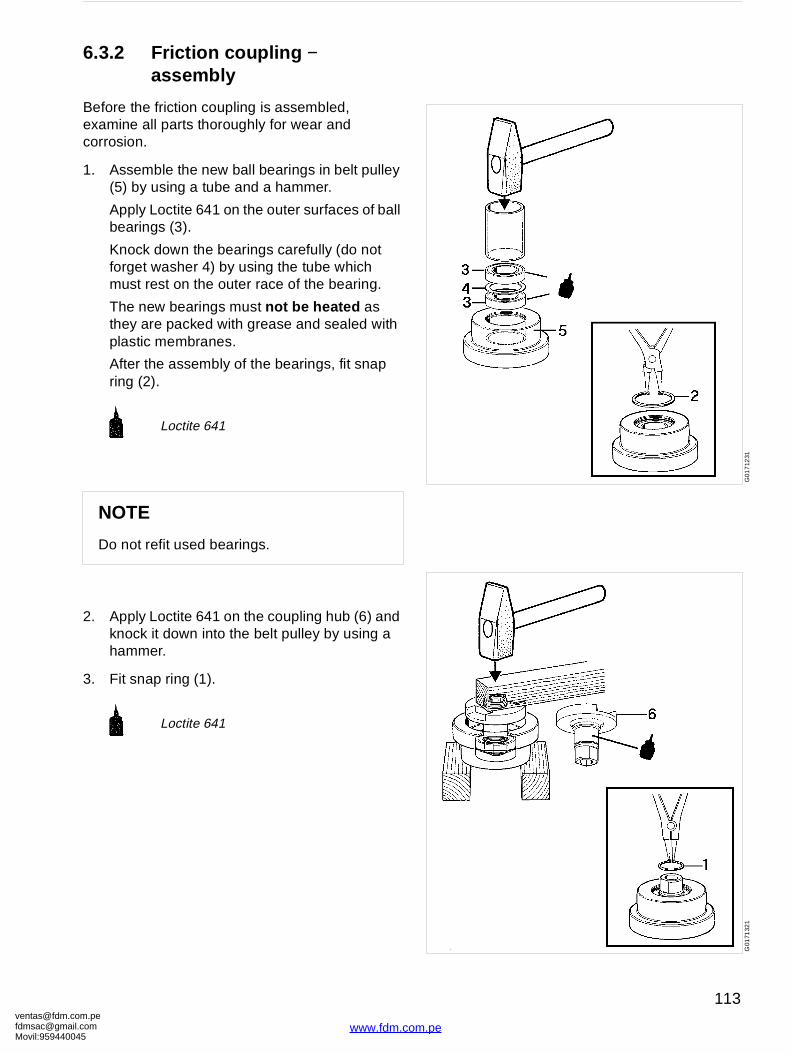
[email protected]@gmaMovil:9594400
G01
712
31G
0171
321
6.3.2 Friction coupling − assembly
Before the friction coupling is assembled, examine all parts thoroughly for wear and corrosion.
1. Assemble the new ball bearings in belt pulley (5) by using a tube and a hammer.
Apply Loctite 641 on the outer surfaces of ball bearings (3).
Knock down the bearings carefully (do not forget washer 4) by using the tube which must rest on the outer race of the bearing.
The new bearings must not be heated as they are packed with grease and sealed with plastic membranes.
After the assembly of the bearings, fit snap ring (2).
2. Apply Loctite 641 on the coupling hub (6) and knock it down into the belt pulley by using a hammer.
3. Fit snap ring (1).
Loctite 641
NOTE
Do not refit used bearings.
Loctite 641
om.peil.com45
113
www.fdm.com.pe
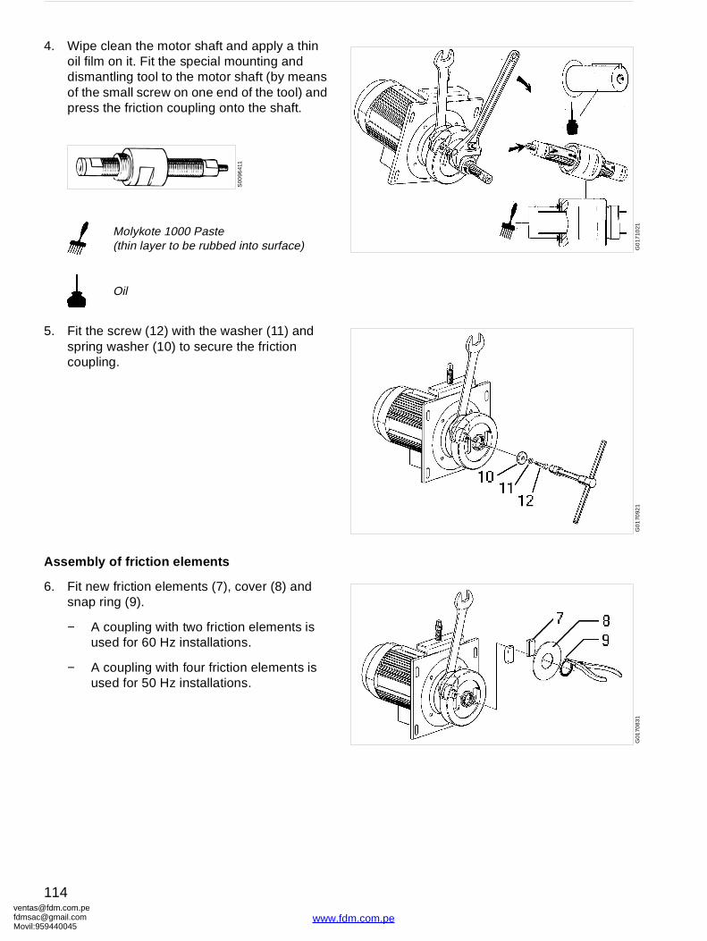
ventafdmsaMovil:
G0
1710
21G
01
7092
1G
0170
831
4. Wipe clean the motor shaft and apply a thin oil film on it. Fit the special mounting and dismantling tool to the motor shaft (by means of the small screw on one end of the tool) and press the friction coupling onto the shaft.
5. Fit the screw (12) with the washer (11) and spring washer (10) to secure the friction coupling.
Assembly of friction elements
6. Fit new friction elements (7), cover (8) and snap ring (9).
− A coupling with two friction elements is used for 60 Hz installations.
− A coupling with four friction elements is used for 50 Hz installations.
Molykote 1000 Paste(thin layer to be rubbed into surface)
Oil
S00
9641
1
[email protected]@gmail.com959440045
114
www.fdm.com.pe
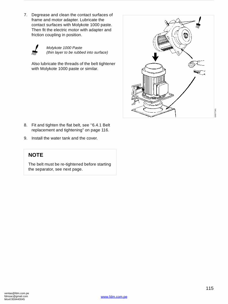
[email protected]@gmaMovil:9594400
G00
7734
1
7. Degrease and clean the contact surfaces of frame and motor adapter. Lubricate the contact surfaces with Molykote 1000 paste. Then fit the electric motor with adapter and friction coupling in position.
Also lubricate the threads of the belt tightener with Molykote 1000 paste or similar.
8. Fit and tighten the flat belt, see ‘‘6.4.1 Belt replacement and tightening” on page 116.
9. Install the water tank and the cover.
Molykote 1000 Paste(thin layer to be rubbed into surface)
NOTE
The belt must be re-tightened before starting the separator, see next page.
om.peil.com45
115
www.fdm.com.pe
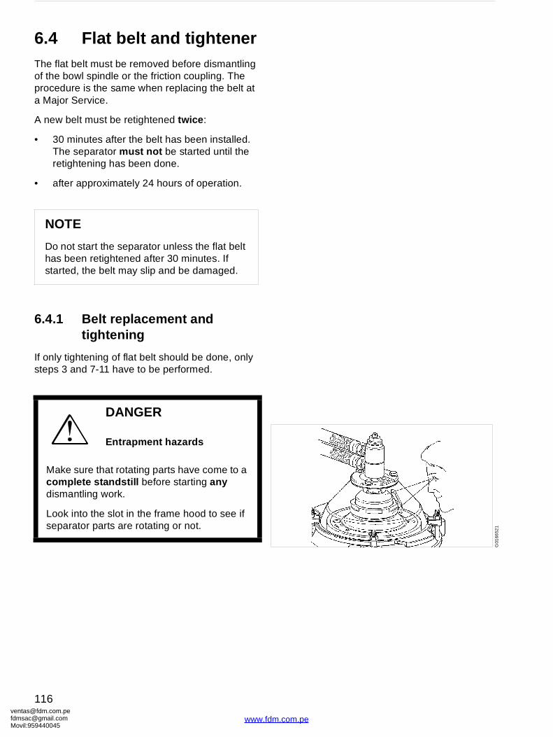
ventafdmsaMovil:
G01
6652
1
6.4 Flat belt and tightenerThe flat belt must be removed before dismantling of the bowl spindle or the friction coupling. The procedure is the same when replacing the belt at a Major Service.
A new belt must be retightened twice :
• 30 minutes after the belt has been installed. The separator must not be started until the retightening has been done.
• after approximately 24 hours of operation.
6.4.1 Belt replacement and tightening
If only tightening of flat belt should be done, only steps 3 and 7-11 have to be performed.
NOTE
Do not start the separator unless the flat belt has been retightened after 30 minutes. If started, the belt may slip and be damaged.
DANGER
Entrapment hazards
Make sure that rotating parts have come to a complete standstill before starting any dismantling work.
Look into the slot in the frame hood to see if separator parts are rotating or not.
[email protected]@gmail.com959440045
116
www.fdm.com.pe
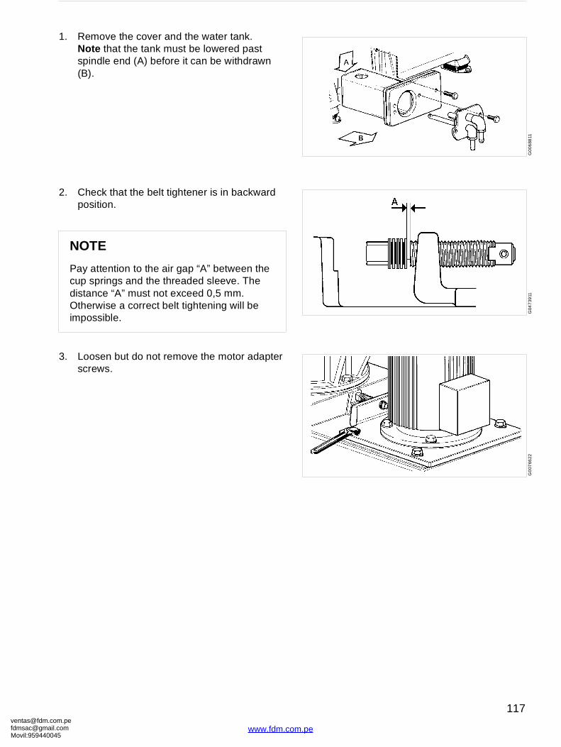
[email protected]@gmaMovil:9594400
G0
0688
11G
047
3911
G0
0766
22
1. Remove the cover and the water tank.Note that the tank must be lowered past spindle end (A) before it can be withdrawn (B).
2. Check that the belt tightener is in backward position.
3. Loosen but do not remove the motor adapter screws.
NOTE
Pay attention to the air gap “A” between the cup springs and the threaded sleeve. The distance “A” must not exceed 0,5 mm. Otherwise a correct belt tightening will be impossible.
om.peil.com45
117
www.fdm.com.pe
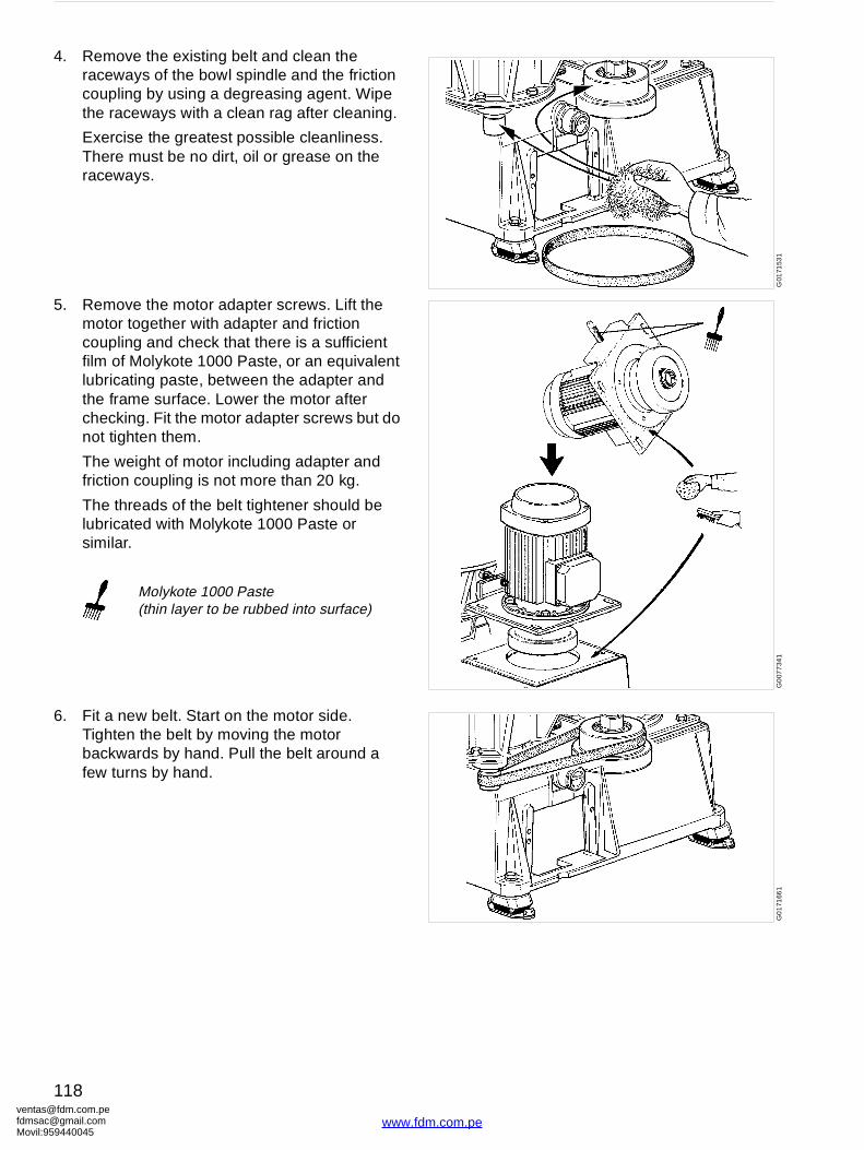
ventafdmsaMovil:
G01
7153
1G
007
734
1G
01
7166
1
4. Remove the existing belt and clean the raceways of the bowl spindle and the friction coupling by using a degreasing agent. Wipe the raceways with a clean rag after cleaning.
Exercise the greatest possible cleanliness. There must be no dirt, oil or grease on the raceways.
5. Remove the motor adapter screws. Lift the motor together with adapter and friction coupling and check that there is a sufficient film of Molykote 1000 Paste, or an equivalent lubricating paste, between the adapter and the frame surface. Lower the motor after checking. Fit the motor adapter screws but do not tighten them.
The weight of motor including adapter and friction coupling is not more than 20 kg.
The threads of the belt tightener should be lubricated with Molykote 1000 Paste or similar.
6. Fit a new belt. Start on the motor side. Tighten the belt by moving the motor backwards by hand. Pull the belt around a few turns by hand.
Molykote 1000 Paste(thin layer to be rubbed into surface)
[email protected]@gmail.com959440045
118
www.fdm.com.pe
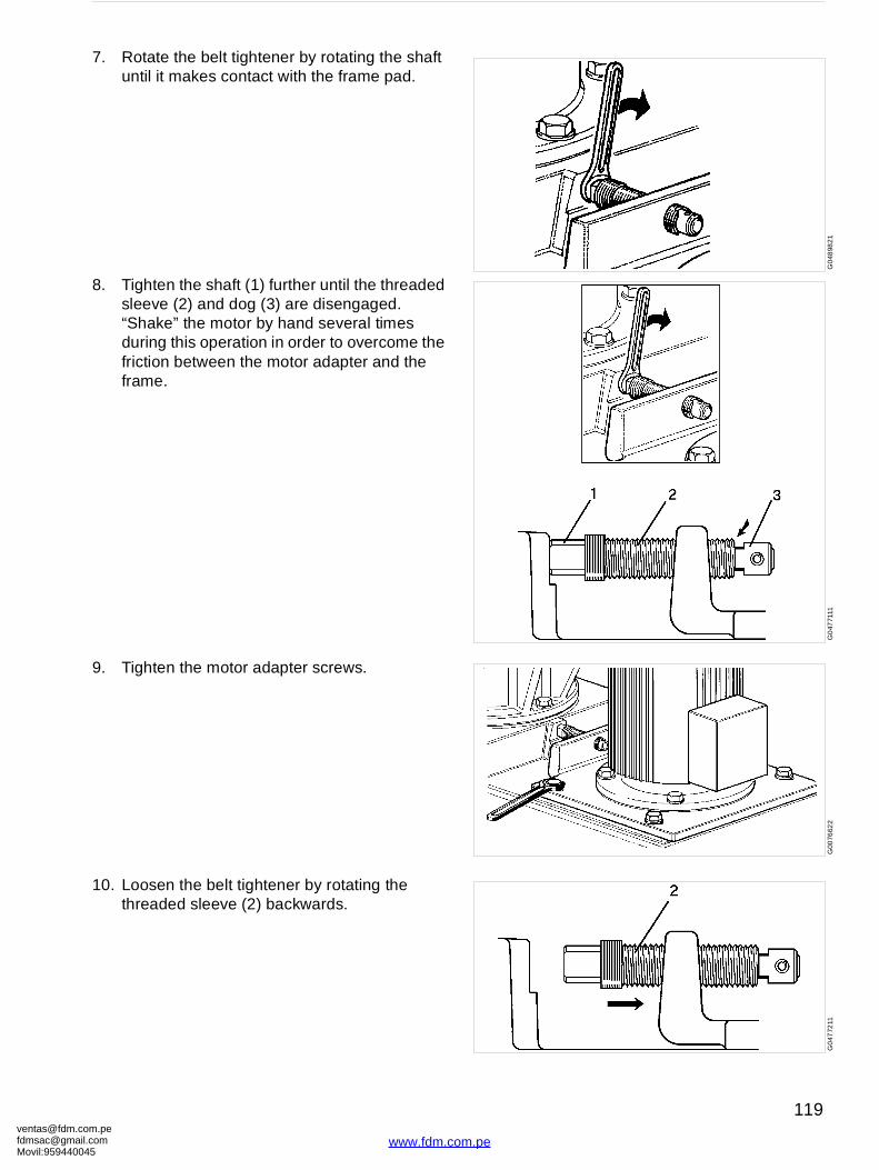
[email protected]@gmaMovil:9594400
G0
4898
21
G0
4771
11G
0076
622
G0
4772
11
7. Rotate the belt tightener by rotating the shaft until it makes contact with the frame pad.
8. Tighten the shaft (1) further until the threaded sleeve (2) and dog (3) are disengaged. “Shake” the motor by hand several times during this operation in order to overcome the friction between the motor adapter and the frame.
9. Tighten the motor adapter screws.
10. Loosen the belt tightener by rotating the threaded sleeve (2) backwards.
om.peil.com45
119
www.fdm.com.pe
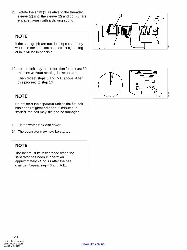
ventafdmsaMovil:
G04
7731
1G
04
7402
1
11. Rotate the shaft (1) relative to the threaded sleeve (2) until the sleeve (2) and dog (3) are engaged again with a clicking sound.
.
12. Let the belt stay in this position for at least 30 minutes without starting the separator.
Then repeat steps 3 and 7-11 above. After this proceed to step 13.
13. Fit the water tank and cover.
14. The separator may now be started.
NOTE
If the springs (4) are not decompressed they will loose their tension and correct tightening of belt will be impossible.
NOTE
Do not start the separator unless the flat belt has been retightened after 30 minutes. If started, the belt may slip and be damaged.
NOTE
The belt must be retightened when the separator has been in operation approximately 24 hours after the belt change: Repeat steps 3 and 7-11.
[email protected]@gmail.com959440045
120
www.fdm.com.pe

[email protected]@gmaMovil:9594400
G0
155
811
G01
559
11
6.5 Oil filling device
6.5.1 Dismantling/assembly
Drain off the oil, see ‘‘5.8 Oil change” on page 71.
Unscrew nipple (4) and pull off the oil filling device. Then unbend the round safety wire (6) and pull off nipple (4).
1. If plate (8) is to be replaced, wipe the sight glass (7) with a degreasing agent.
2. Fit the new plate on the outside of the sight glass. The plate is self-adhesive.
3. Mark the position of the plate relative to the recess in sleeve (1).
Assemble the oil filling device and fit it into the frame. Note that the mark on sleeve (1) must be positioned opposite the mark on the frame. Fill the sump with new oil.
1 Sleeve for oil filling2 O-ring3 O-ring4 Nipple
5 Sealing ring6 Round safety wire7 Sight glass8 Plate
Silicone grease (thin layer)
om.peil.com45
121
www.fdm.com.pe
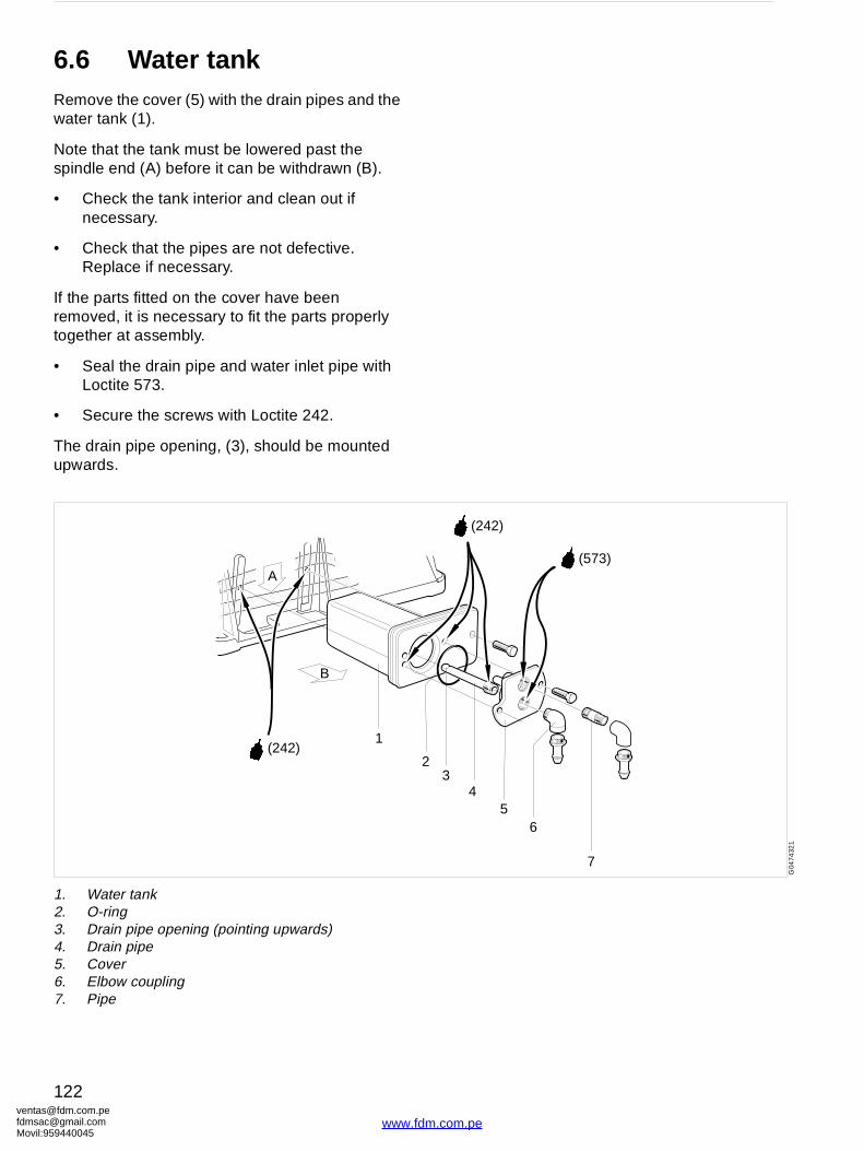
ventafdmsaMovil:
23
4
(573)
(242)
56
7
G04
7432
1
6.6 Water tankRemove the cover (5) with the drain pipes and the water tank (1).
Note that the tank must be lowered past the spindle end (A) before it can be withdrawn (B).
• Check the tank interior and clean out if necessary.
• Check that the pipes are not defective. Replace if necessary.
If the parts fitted on the cover have been removed, it is necessary to fit the parts properly together at assembly.
• Seal the drain pipe and water inlet pipe with Loctite 573.
• Secure the screws with Loctite 242.
The drain pipe opening, (3), should be mounted upwards.
A
B
1(242)
1. Water tank2. O-ring3. Drain pipe opening (pointing upwards)4. Drain pipe5. Cover6. Elbow coupling7. Pipe
[email protected]@gmail.com959440045
122
www.fdm.com.pe
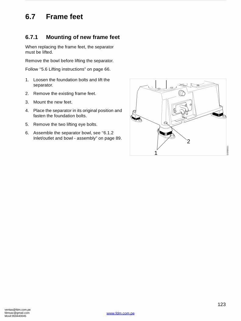
[email protected]@gmaMovil:9594400
1
2
G03
5832
1
6.7 Frame feet
6.7.1 Mounting of new frame feet
When replacing the frame feet, the separator must be lifted.
Remove the bowl before lifting the separator.
Follow ‘‘5.6 Lifting instructions” on page 66.
1. Loosen the foundation bolts and lift the separator.
2. Remove the existing frame feet.
3. Mount the new feet.
4. Place the separator in its original position and fasten the foundation bolts.
5. Remove the two lifting eye bolts.
6. Assemble the separator bowl, see ‘‘6.1.2 Inlet/outlet and bowl - assembly” on page 89.
om.peil.com45
123
www.fdm.com.pe
[email protected]@gmaMovil:9594400
7 Trouble-tracing
Contents
7.1 Trouble-tracing procedure 126
7.2 MMPX mechanical function 126
7.2.1 The separator does not start 126
7.2.2 Start-up time too long 126
7.2.3 Starting power too low 126
7.2.4 Starting power too high 127
7.2.5 Separator vibrates duringstarting sequence 128
7.2.6 Separator vibrates duringnormal running 129
7.2.7 Smell 130
7.2.8 Noise 130
7.2.9 Speed too high 130
7.2.10 Speed too low 131
7.2.11 Water in oil sump 131
7.3 Purification and clarification faults 132
7.3.1 Liquid flows through bowl casing drain and/or sludge outlet 132
7.3.2 Bowl opens unintentionally during operation 133
7.3.3 Bowl fails to open for sludgedischarge 133
7.3.4 Unsatisfactory sludge discharge 133
7.4 Purification faults 134
7.4.1 Unsatisfactory separationresult 134
7.4.2 Outgoing water contains oil 134
7.4.3 Oil discharge through water outlet = broken water seal 135
7.5 Clarification faults 136
7.5.1 Unsatisfactory separation result 136
7.5.2 Oil discharge through water outlet 136
om.peil.com45
www.fdm.co
125
m.pe
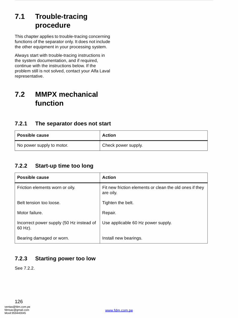
ventafdmsaMovil:
power supply.
friction elements or clean the old ones if they .
the belt.
.
plicable 60 Hz power supply.
new bearings.
7.1 Trouble-tracing procedure
This chapter applies to trouble-tracing concerning functions of the separator only. It does not include the other equipment in your processing system.
Always start with trouble-tracing instructions in the system documentation, and if required, continue with the instructions below. If the problem still is not solved, contact your Alfa Laval representative.
7.2 MMPX mechanical function
7.2.1 The separator does not start
7.2.2 Start-up time too long
7.2.3 Starting power too low
See 7.2.2.
Possible cause Action
No power supply to motor. Check
Possible cause Action
Friction elements worn or oily. Fit neware oily
Belt tension too loose. Tighten
Motor failure. Repair
Incorrect power supply (50 Hz instead of 60 Hz).
Use ap
Bearing damaged or worn. Install
[email protected]@gmail.com959440045
126
www.fdm.com.pe
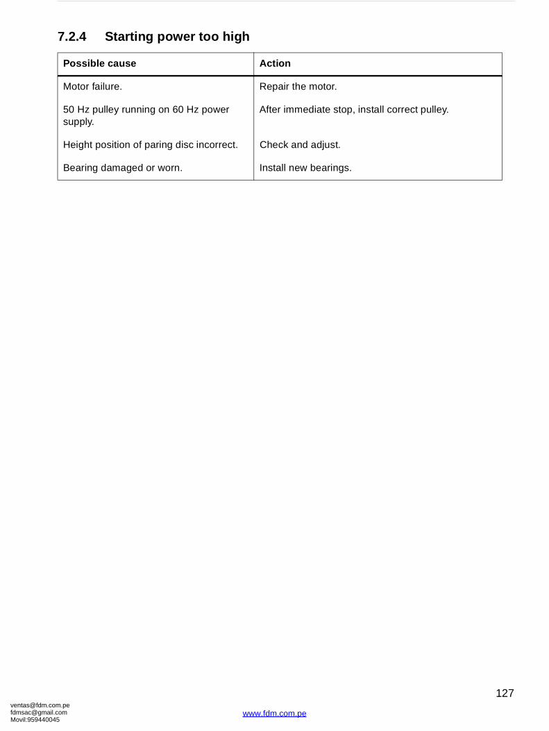
[email protected]@gmaMovil:9594400
the motor.
mediate stop, install correct pulley.
and adjust.
new bearings.
7.2.4 Starting power too high
Possible cause Action
Motor failure. Repair
50 Hz pulley running on 60 Hz power supply.
After im
Height position of paring disc incorrect. Check
Bearing damaged or worn. Install
om.peil.com45
127
www.fdm.com.pe
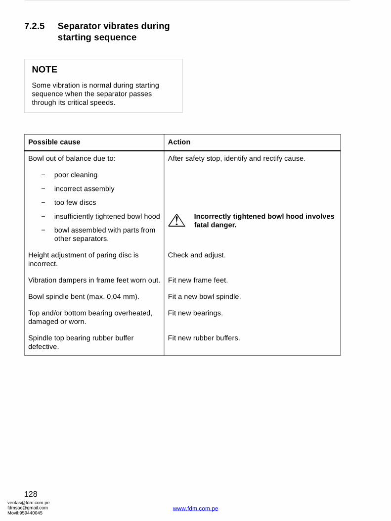
ventafdmsaMovil:
afety stop, identify and rectify cause.
Incorrectly tightened bowl hood involves fatal danger.
and adjust.
frame feet.
w bowl spindle.
bearings.
rubber buffers.
7.2.5 Separator vibrates duringstarting sequence
NOTE
Some vibration is normal during starting sequence when the separator passes through its critical speeds.
Possible cause Action
Bowl out of balance due to: After s
− poor cleaning
− incorrect assembly
− too few discs
− insufficiently tightened bowl hood
− bowl assembled with parts from other separators.
Height adjustment of paring disc is incorrect.
Check
Vibration dampers in frame feet worn out. Fit new
Bowl spindle bent (max. 0,04 mm). Fit a ne
Top and/or bottom bearing overheated, damaged or worn.
Fit new
Spindle top bearing rubber buffer defective.
Fit new
[email protected]@gmail.com959440045
128
www.fdm.com.pe

[email protected]@gmaMovil:9594400
.4 Purification faults’’ and ‘‘7.5 Clarification .
bearings.
frame feet.
rubber buffers.
7.2.6 Separator vibrates duringnormal running
DANGER
Disintegration hazards
Never discharge a vibrating separator.
Possible cause Action
Uneven sludge deposits in sludge space. See ‘‘7faults’’
Bearing damaged or worn. Fit new
Vibration dampers in frame feet worn out. Fit new
Spindle top bearing rubber buffer defective.
Fit new
om.peil.com45
129
www.fdm.com.pe
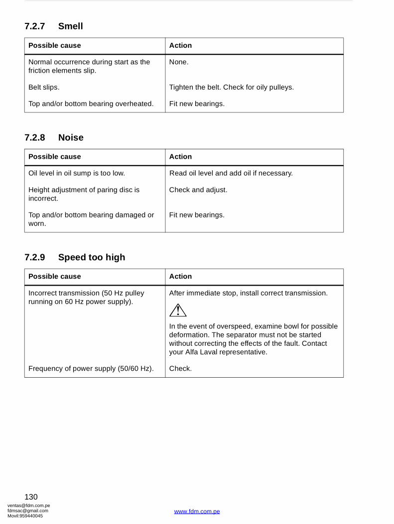
ventafdmsaMovil:
the belt. Check for oily pulleys.
bearings.
il level and add oil if necessary.
and adjust.
bearings.
mediate stop, install correct transmission.
vent of overspeed, examine bowl for possible ation. The separator must not be started t correcting the effects of the fault. Contact lfa Laval representative.
7.2.7 Smell
7.2.8 Noise
7.2.9 Speed too high
Possible cause Action
Normal occurrence during start as the friction elements slip.
None.
Belt slips. Tighten
Top and/or bottom bearing overheated. Fit new
Possible cause Action
Oil level in oil sump is too low. Read o
Height adjustment of paring disc is incorrect.
Check
Top and/or bottom bearing damaged or worn.
Fit new
Possible cause Action
Incorrect transmission (50 Hz pulley running on 60 Hz power supply).
After im
In the edeformwithouyour A
Frequency of power supply (50/60 Hz). Check.
[email protected]@gmail.com959440045
130
www.fdm.com.pe
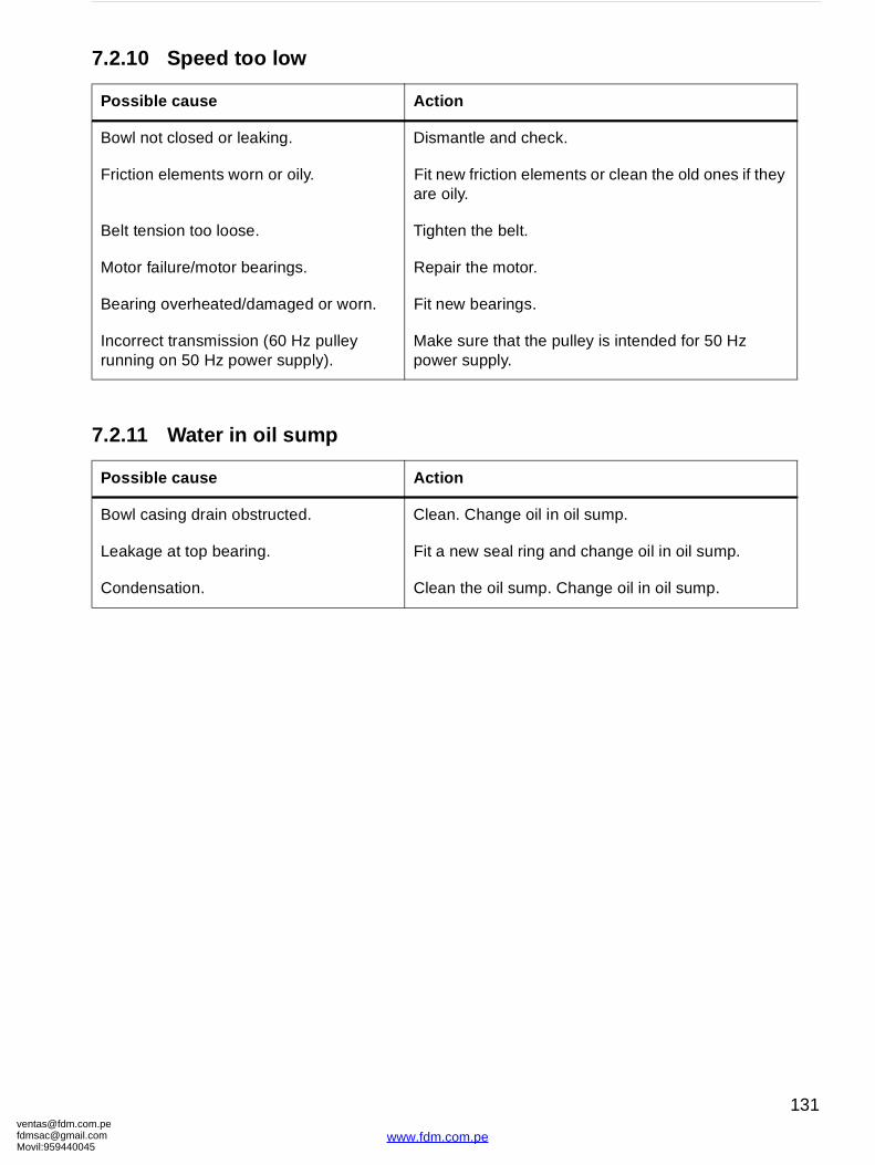
[email protected]@gmaMovil:9594400
ntle and check.
friction elements or clean the old ones if they .
the belt.
the motor.
bearings.
ure that the pulley is intended for 50 Hz supply.
Change oil in oil sump.
w seal ring and change oil in oil sump.
the oil sump. Change oil in oil sump.
7.2.10 Speed too low
7.2.11 Water in oil sump
Possible cause Action
Bowl not closed or leaking. Disma
Friction elements worn or oily. Fit neware oily
Belt tension too loose. Tighten
Motor failure/motor bearings. Repair
Bearing overheated/damaged or worn. Fit new
Incorrect transmission (60 Hz pulley running on 50 Hz power supply).
Make spower
Possible cause Action
Bowl casing drain obstructed. Clean.
Leakage at top bearing. Fit a ne
Condensation. Clean
om.peil.com45
131
www.fdm.com.pe

ventafdmsaMovil:
normal).
.4.3 Oil discharge through water outlet = water seal” on page 135.
ten the hose. Clean the strainer. Check the ressure.
w seal ring.
a new seal ring.
a new seal ring. Polish the surface on sliding ottom or install a new one.
new valve plugs.
the operating slide.
seal rings.
ure current is on. Retighten the flat belt or t motor and power transmission.
7.3 Purification and clarification faults
7.3.1 Liquid flows through bowl casing drain and/or sludge outlet
Possible cause Action
Sludge discharge or water draining in progress.
None (
Broken water seal. See ‘‘7broken
Displacement water volume too large. Adjust.
The supply of operating water is not sufficient due to clogged strainer, kinked hose or low water pressure.
Straighwater p
Seal ring on gravity disc/clarifier disc defective.
Fit a ne
Seal ring in sliding bowl bottom defective. Install
Bowl hood seal ring defective or sealing surface of sliding bowl bottom damaged.
Install bowl b
Valve plugs defective. Install
Sludge deposits on operating slide. Clean
Seal rings in paring disc device defective. Fit new
Bowl speed too low. Make sinspec
[email protected]@gmail.com959440045
132
www.fdm.com.pe
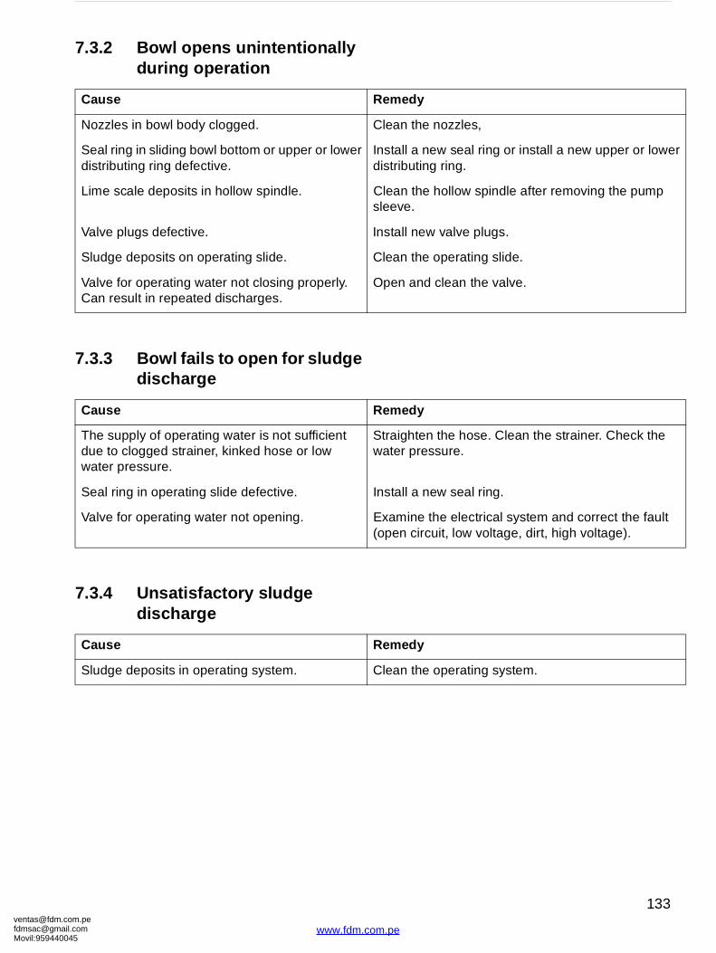
[email protected]@gmaMovil:9594400
emedy
lean the nozzles,
nstall a new seal ring or install a new upper or lower istributing ring.
lean the hollow spindle after removing the pump leeve.
nstall new valve plugs.
lean the operating slide.
pen and clean the valve.
emedy
traighten the hose. Clean the strainer. Check the ater pressure.
nstall a new seal ring.
xamine the electrical system and correct the fault open circuit, low voltage, dirt, high voltage).
emedy
lean the operating system.
7.3.2 Bowl opens unintentionally during operation
7.3.3 Bowl fails to open for sludge discharge
7.3.4 Unsatisfactory sludge discharge
Cause R
Nozzles in bowl body clogged. C
Seal ring in sliding bowl bottom or upper or lower distributing ring defective.
Id
Lime scale deposits in hollow spindle. Cs
Valve plugs defective. I
Sludge deposits on operating slide. C
Valve for operating water not closing properly. Can result in repeated discharges.
O
Cause R
The supply of operating water is not sufficient due to clogged strainer, kinked hose or low water pressure.
Sw
Seal ring in operating slide defective. I
Valve for operating water not opening. E(
Cause R
Sludge deposits in operating system. C
om.peil.com45
133
www.fdm.com.pe

ventafdmsaMovil:
gravity disc with a larger hole.
temperature.
e throughput.
the bowl and shorten time between rges.
the bowl discs.
.2.10 Speed too low” on page 131.
gravity disc with a smaller hole.
w seal ring.
ten the hose. Clean the strainer. Check the ressure.
7.4 Purification faults
7.4.1 Unsatisfactory separationresult
7.4.2 Outgoing water contains oil
Possible cause Action
Gravity disc hole too small.
Incorrect separating temperature.
Throughput too high.
Use a
Adjust
Reduc
Sludge space in bowl is filled with sludge. Clean discha
Disc stack clogged. Clean
Inlet clogged. Clean.
Bowl speed too low. See ‘‘7
Possible cause Action
Gravity disc hole too large. Use a
Seal ring under the gravity disc defective. Fit a ne
The supply of operating water is not sufficient due to clogged strainer, kinked hose or low water pressure.
Straighwater p
[email protected]@gmail.com959440045
134
www.fdm.com.pe
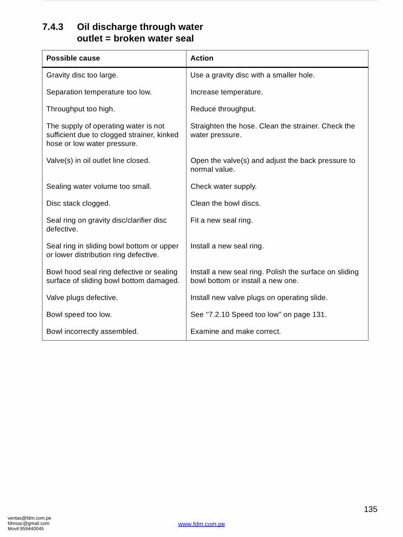
[email protected]@gmaMovil:9594400
gravity disc with a smaller hole.
e temperature.
e throughput.
ten the hose. Clean the strainer. Check the ressure.
he valve(s) and adjust the back pressure to l value.
water supply.
the bowl discs.
w seal ring.
a new seal ring.
a new seal ring. Polish the surface on sliding ottom or install a new one.
new valve plugs on operating slide.
.2.10 Speed too low” on page 131.
e and make correct.
7.4.3 Oil discharge through water outlet = broken water seal
Possible cause Action
Gravity disc too large. Use a
Separation temperature too low. Increas
Throughput too high. Reduc
The supply of operating water is not sufficient due to clogged strainer, kinked hose or low water pressure.
Straighwater p
Valve(s) in oil outlet line closed. Open tnorma
Sealing water volume too small. Check
Disc stack clogged. Clean
Seal ring on gravity disc/clarifier disc defective.
Fit a ne
Seal ring in sliding bowl bottom or upper or lower distribution ring defective.
Install
Bowl hood seal ring defective or sealing surface of sliding bowl bottom damaged.
Install bowl b
Valve plugs defective. Install
Bowl speed too low. See ‘‘7
Bowl incorrectly assembled. Examin
om.peil.com45
135
www.fdm.com.pe
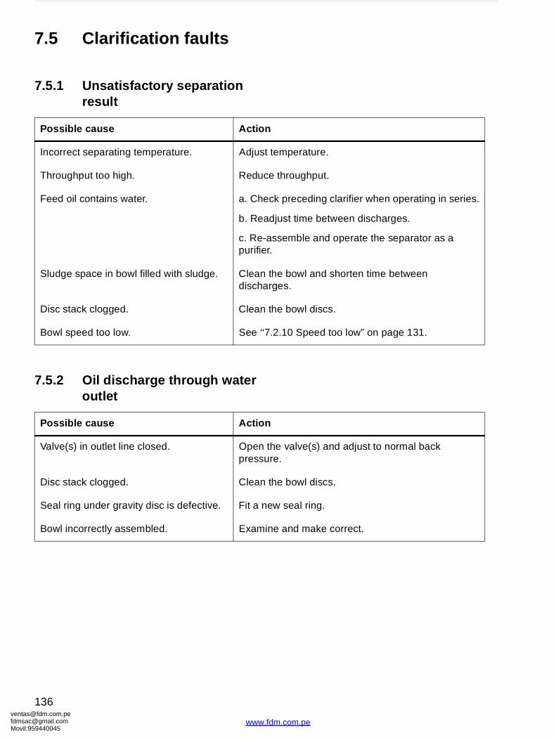
ventafdmsaMovil:
temperature.
e throughput.
ck preceding clarifier when operating in series.
djust time between discharges.
ssemble and operate the separator as a .
the bowl and shorten time between rges.
the bowl discs.
.2.10 Speed too low” on page 131.
he valve(s) and adjust to normal back re.
the bowl discs.
w seal ring.
e and make correct.
7.5 Clarification faults
7.5.1 Unsatisfactory separation result
7.5.2 Oil discharge through water outlet
Possible cause Action
Incorrect separating temperature. Adjust
Throughput too high. Reduc
Feed oil contains water. a. Che
b. Rea
c. Re-apurifier
Sludge space in bowl filled with sludge. Clean discha
Disc stack clogged. Clean
Bowl speed too low. See ‘‘7
Possible cause Action
Valve(s) in outlet line closed. Open tpressu
Disc stack clogged. Clean
Seal ring under gravity disc is defective. Fit a ne
Bowl incorrectly assembled. Examin
[email protected]@gmail.com959440045
136
www.fdm.com.pe
[email protected]@gmaMovil:9594400
8 Technical Reference
Contents
8.1 Technical data 138
8.2 Connection list 141
8.3 Interface description 143
8.3.1 General 143
8.3.2 Definitions 143
8.3.3 Component description and signal processing 144
8.4 Water quality 146
8.5 Lubricants 147
8.5.1 Lubrication chart 147
8.5.2 Alfa Laval lubricating oil groups: 148
8.5.3 Recommended lubricants 150
8.5.4 Recommended lubricating oils 152
8.5.5 Recommended oil brands 153
8.6 Drawings 156
8.6.1 Basic size drawing 156
8.6.2 Foundation plan 157
8.6.3 Dimensions of connections 158
8.6.4 Electric motor 160
8.6.5 Machine plates and safety labels 164
8.6.6 Gravity disc nomogram 166
8.7 Storage and installation 168
8.7.1 Storage and transport of goods 168
8.7.2 Planning of installation 171
8.7.3 Foundations 172
om.peil.com45
www.fdm.co
137
m.pe
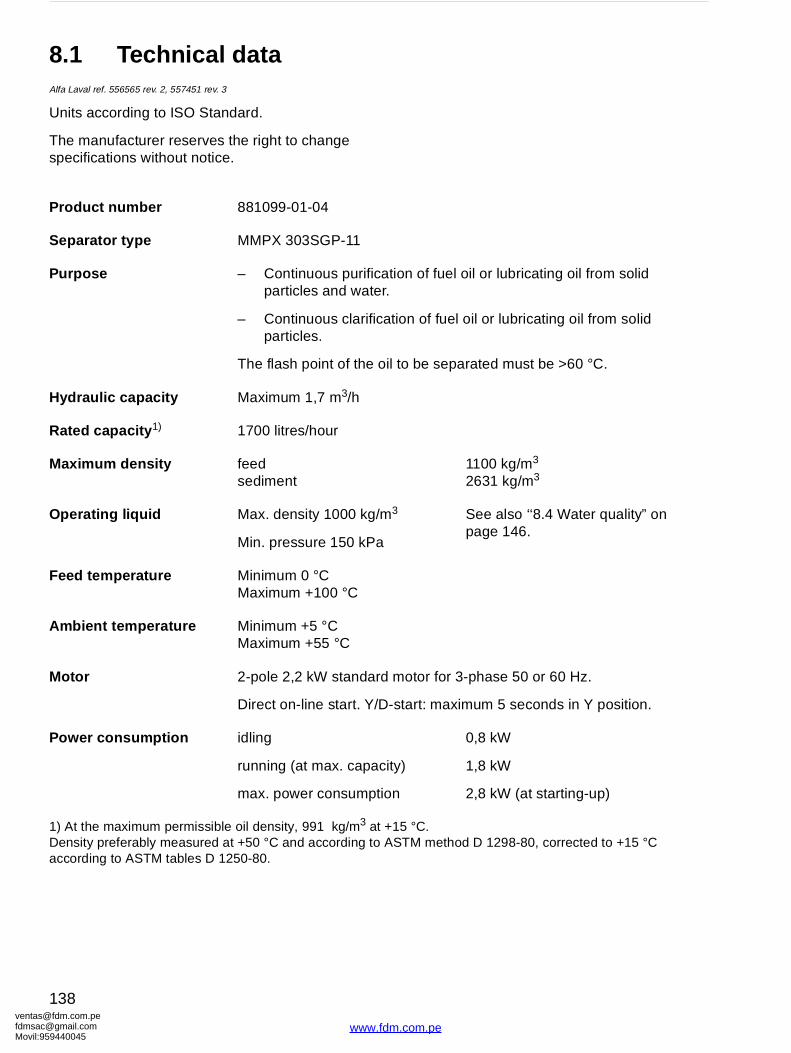
ventafdmsaMovil:
tion of fuel oil or lubricating oil from solid r.
ation of fuel oil or lubricating oil from solid
il to be separated must be >60 °C.
1100 kg/m3
2631 kg/m3
3 See also ‘‘8.4 Water quality” on page 146.
motor for 3-phase 50 or 60 Hz.
-start: maximum 5 seconds in Y position.
ity)
on
0,8 kW
1,8 kW
2,8 kW (at starting-up)
+15 °C. ASTM method D 1298-80, corrected to +15 °C
8.1 Technical dataAlfa Laval ref. 556565 rev. 2, 557451 rev. 3
Units according to ISO Standard.
The manufacturer reserves the right to change specifications without notice.
Product number 881099-01-04
Separator type MMPX 303SGP-11
Purpose – Continuous purificaparticles and wate
– Continuous clarificparticles.
The flash point of the o
Hydraulic capacity Maximum 1,7 m3/h
Rated capacity 1) 1700 litres/hour
Maximum density feedsediment
Operating liquid Max. density 1000 kg/m
Min. pressure 150 kPa
Feed temperature Minimum 0 °CMaximum +100 °C
Ambient temperature Minimum +5 °CMaximum +55 °C
Motor 2-pole 2,2 kW standard
Direct on-line start. Y/D
Power consumption idling
running (at max. capac
max. power consumpti
1) At the maximum permissible oil density, 991 kg/m3 at Density preferably measured at +50 °C and according to according to ASTM tables D 1250-80.
[email protected]@gmail.com959440045
138
www.fdm.com.pe
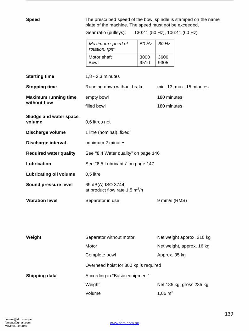
[email protected]@gmaMovil:9594400
of the bowl spindle is stamped on the name he speed must not be exceeded.
130:41 (50 Hz), 106:41 (60 Hz)
brake min. 13, max. 15 minutes
180 minutes
180 minutes
” on page 146
n page 147
m3/h
9 mm/s (RMS)
r Net weight approx. 210 kg
Net weight, approx. 16 kg
Approx. 35 kg
kp is required
uipment”
Net 185 kg, gross 235 kg
1,06 m3
50 Hz 60 Hz
30009510
36009305
Speed The prescribed speed plate of the machine. T
Gear ratio (pulleys):.
Starting time 1,8 - 2,3 minutes
Stopping time Running down without
Maximum running time without flow
empty bowl
filled bowl
Sludge and water space volume 0,6 litres net
Discharge volume 1 litre (nominal), fixed
Discharge interval minimum 2 minutes
Required water quality See ‘‘8.4 Water quality
Lubrication See ‘‘8.5 Lubricants” o
Lubricating oil volume 0,5 litre
Sound pressure level 69 dB(A) ISO 3744, at product flow rate 1,5
Vibration level Separator in use
Weight Separator without moto
Motor
Complete bowl
Overhead hoist for 300
Shipping data According to “Basic eq
Weight
Volume
Maximum speed of rotation, rpm
Motor shaft Bowl
om.peil.com45
139
www.fdm.com.pe
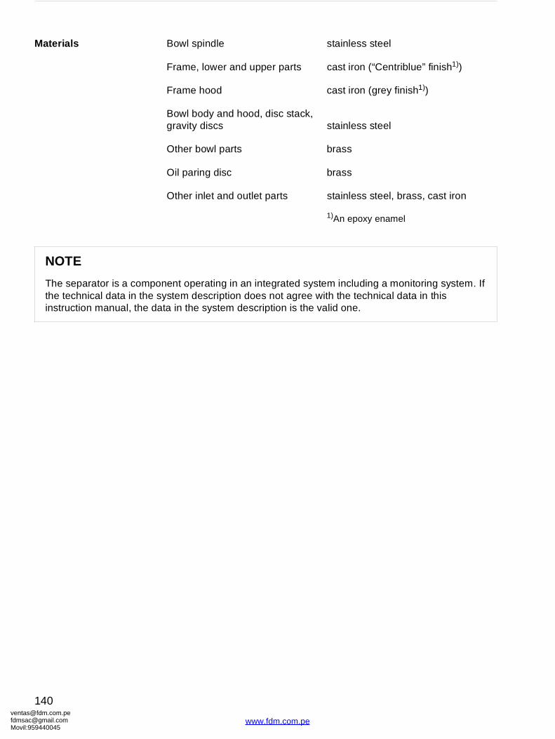
ventafdmsaMovil:
stainless steel
r parts cast iron (“Centriblue” finish1))
cast iron (grey finish1))
isc stack, stainless steel
brass
brass
arts stainless steel, brass, cast iron
1)An epoxy enamel
grated system including a monitoring system. If not agree with the technical data in this tion is the valid one.
Materials Bowl spindle
Frame, lower and uppe
Frame hood
Bowl body and hood, dgravity discs
Other bowl parts
Oil paring disc
Other inlet and outlet p
NOTE
The separator is a component operating in an intethe technical data in the system description does instruction manual, the data in the system descrip
[email protected]@gmail.com959440045
140
www.fdm.com.pe
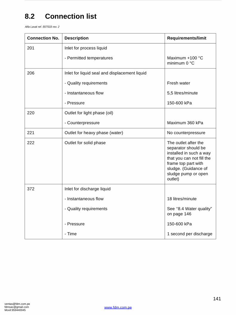
[email protected]@gmaMovil:9594400
Requirements/limit
Maximum +100 °Cminimum 0 °C
ment liquid
Fresh water
5,5 litres/minute
150-600 kPa
Maximum 360 kPa
No counterpressure
The outlet after the separator should be installed in such a way that you can not fill the frame top part with sludge. (Guidance of sludge pump or open outlet)
18 litres/minute
See ‘‘8.4 Water quality” on page 146
150-600 kPa
1 second per discharge
8.2 Connection listAlfa Laval ref. 557533 rev. 2
Connection No. Description
201 Inlet for process liquid
- Permitted temperatures
206 Inlet for liquid seal and displace
- Quality requirements
- Instantaneous flow
- Pressure
220 Outlet for light phase (oil)
- Counterpressure
221 Outlet for heavy phase (water)
222 Outlet for solid phase
372 Inlet for discharge liquid
- Instantaneous flow
- Quality requirements
- Pressure
- Time
om.peil.com45
141
www.fdm.com.pe

ventafdmsaMovil:
0,9 litre per minute
See ‘‘8.4 Water quality” on page 146
150-600 kPa
0,9 litre per discharge
open
frequency5 seconds
Maximum ±5%±10%)
Requirements/limit
Location of connections on the separator, see ‘‘8.6.1 Basic size drawing” on page 156, and ‘‘8.6.3 Dimensions of connections” on page 158.
373 Inlet for closing liquid
- Instantaneous flow
- Quality requirements
- Pressure
- Consumption
377 Outlet for operating liquid
462 Drain of frame top part, lower
463 Drain of frame top part, upper
701 Motor for separator
Allowed deviation from nominal(momentarily during maximum
Connection No. Description
[email protected]@gmail.com959440045
142
www.fdm.com.pe
[email protected]@gmaMovil:9594400
8.3 Interface descriptionAlfa Laval ref. 557469 rev. 1
8.3.1 General
In addition to the ‘‘8.2 Connection list” on page 141 this document describes limitations and conditions for safe control, monitoring and reliable operation.
At the end of the document a function graph and running limitations are found.
8.3.2 Definitions
Stand still (Ready for start) means:
• The machine is assembled correctly.
• All connections are installed according to Connection List, Interconnection Diagram and Interface Description.
Start means:
• The power to the separator is on.
• The acceleration is supervised to ensure that a certain speed has been reached within a certain time. See ‘‘8.1 Technical data” on page 138.
The start procedure continues until the full speed has been reached and a stabilisation period has passed (about one (1) minute).
Normal stop means:
• Stopping of the machine at any time.
• The bowl must be kept filled.
om.peil.com45
143
www.fdm.com.pe
ventafdmsaMovil:
Safety stop means:
The machine must be stopped in the quickest and safest way due to vibrations or process reasons.
Comply to the following conditions:
• The bowl must be kept filled.
• Sludge ejection (sludge discharge) must not be made.
• The machine must not be restarted before the reason for the safety stop has been investigated and action has been taken.
In case of emergency condition in the plant, the machine must be stopped in a way that is described in EN 418.
8.3.3 Component description and signal processing
Separator motor 701
The separator is equipped with a 3-phase DOL- (direct-on-line) started motor. The separator can also be started by a Y/D starter, but then the time in Y-position must be maximized to 5 seconds.
Discharge signal processing
The control system shall contain a memory function for registration of the number of initiated discharges.
At indication of the absence of a discharge the operator or the control system must initiate a new discharge.
At indication of the absence of two consecutive sludge discharges an alarm must be given and action must be taken.
[email protected]@gmail.com959440045
144
www.fdm.com.pe
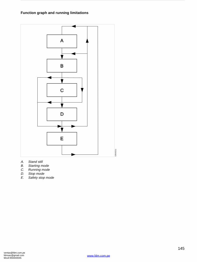
[email protected]@gmaMovil:9594400
G05
4321
1
Function graph and running limitations
A. Stand stillB. Starting modeC. Running modeD. Stop modeE. Safety stop mode
A
B
C
D
E
om.peil.com45
145
www.fdm.com.pe
ventafdmsaMovil:
nctions: Discharge-flushing.
, corrosion and/or re be treated to meet
rtance.
volume.
areas in the
(corresponds to ature accelerates the
60mg Cl/l).
arator surfaces in pindle. Corrosion is a ting temperature, low ide concentration
n; this is accelerated n content.
tive.
e pretreated
ing from er.
8.4 Water qualityAlfa Laval ref. 553406 rev. 3
Specific requirements regarding the quality of water
Water is used in the separator for several different fumechanisms, liquid seals, as cooling media and for
Bad quality of the water can with time cause erosionoperating problems in the separator and must therefocertain demands.
The following requirements are of fundamental impo
1.1 Turbidity-free water, solids content < 0,001% of
Deposits must not be allowed to form in certain separator.
1.2 Max particle size 50 m.
2. Total hardness ≤ 180 mg CaCo3 per litre.
Chalk deposits can build-up if the water is hard 10 °dH or 12,5 °E). Increased operating temperchalk built-ups.
3. Chloride content ≤ 100 ppm NaCl (equivalent to
Chloride ions contribute to corrosion on the sepcontact with the operating water, including the sprocess that is accelerated by increased separapH, and high chloride ion concentration. A chlorabove 60 mg/l is not recommended.
4. pH > 6
Increasing acidity (lower pH) increases corrosioby increased temperatures and high chloride io
For test methods, contact any Alfa Laval representa
If these demands cannot be met, the water should baccording to Alfa Laval's recommendations.
Alfa Laval accepts no liability for consequences arisunsatisfactorily purified water supplied by the custom
[email protected]@gmail.com959440045
146
www.fdm.com.pe
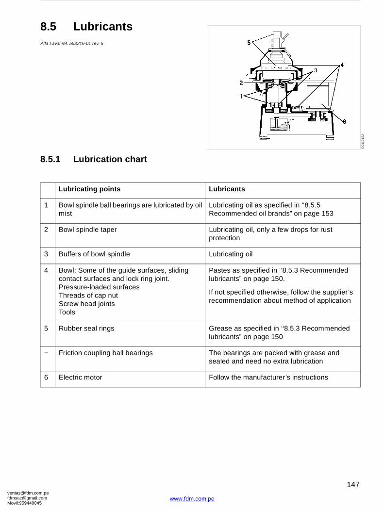
[email protected]@gmaMovil:9594400
Lubricants
Lubricating oil as specified in ‘‘8.5.5 Recommended oil brands” on page 153
Lubricating oil, only a few drops for rust protection
Lubricating oil
Pastes as specified in ‘‘8.5.3 Recommended lubricants” on page 150.
If not specified otherwise, follow the supplier’s recommendation about method of application
Grease as specified in ‘‘8.5.3 Recommended lubricants” on page 150
The bearings are packed with grease and sealed and need no extra lubrication
Follow the manufacturer’s instructions
G0
1121
22
8.5 LubricantsAlfa Laval ref. 553216-01 rev. 5
8.5.1 Lubrication chart
Lubricating points
1 Bowl spindle ball bearings are lubricated by oilmist
2 Bowl spindle taper
3 Buffers of bowl spindle
4 Bowl: Some of the guide surfaces, sliding contact surfaces and lock ring joint.Pressure-loaded surfacesThreads of cap nutScrew head jointsTools
5 Rubber seal rings
− Friction coupling ball bearings
6 Electric motor
om.peil.com45
147
www.fdm.com.pe
ventafdmsaMovil:
8.5.2 Alfa Laval lubricating oil groups:
• Group A oil: a high quality gear oil on paraffin base with stable AW (anti-wear) additives.
• Group B oil: a high quality gear oil on paraffin base with stable EP (extreme pressure) additives.
• Group D oil: a synthetic-base oil with additives stable at high operating temperatures.
Do not mix different oil brands or oils from different oil groups.
Always use clean vessels when handling lubricating oil.
Great attention must be paid not to contaminate the lubricating oil. Of particular importance is to avoid mixing of different types of oil. Even a few drops of motor oil mixed into a synthetic oil may result in severe foaming.
Any presence of black deposits in a mineral type oil is an indication that the oil base has deteriorated seriously or that some of the oil additives have precipitated. Always investigate why black deposits occur.
If it is necessary to change from one group of oil brand to another it is recommended to do this in connection with an overhaul of the separator. Clean the oil sump and the spindle parts thoroughly and remove all deposits before filling the new oil.
NOTE
Always clean and dry parts (also tools) before lubricants are applied.
NOTE
Check the oil level before start. Top up when necessary. Oil volume see ‘‘8.1 Technical data” on page 138.
[email protected]@gmail.com959440045
148
www.fdm.com.pe
[email protected]@gmaMovil:9594400
It is of utmost importance to use the lubricants recommended in our documentation. This does not exclude, however, the use of other brands, provided they have equivalently high quality properties as the brands recommended. The use of oil brands and other lubricants than recommended, is done on the exclusive responsibility of the user or oil supplier.
Applying, handling and storing of lubricants
Always be sure to follow lubricant manufacturer’s instructions.
CAUTION
Skin irritation hazard
Personnel handling the oil must be instructed in its use (e.g. the possible risk of skin irritation, dermatitis). Ask for and follow the instructions from the oil supplier.
Spray should only be used in well ventilated localities.
om.peil.com45
149
www.fdm.com.pe
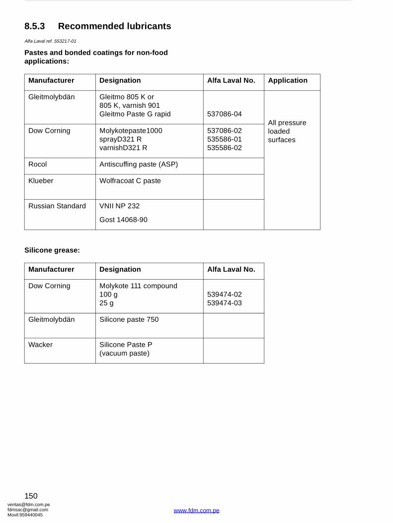
ventafdmsaMovil:
Alfa Laval No. Application
537086-04All pressure loaded surfaces
537086-02535586-01535586-02
Alfa Laval No.
539474-02539474-03
8.5.3 Recommended lubricantsAlfa Laval ref. 553217-01
Pastes and bonded coatings for non-food applications:
Silicone grease:
Manufacturer Designation
Gleitmolybdän Gleitmo 805 K or805 K, varnish 901Gleitmo Paste G rapid
Dow Corning Molykotepaste1000sprayD321 RvarnishD321 R
Rocol Antiscuffing paste (ASP)
Klueber Wolfracoat C paste
Russian Standard VNII NP 232
Gost 14068-90
Manufacturer Designation
Dow Corning Molykote 111 compound100 g25 g
Gleitmolybdän Silicone paste 750
Wacker Silicone Paste P(vacuum paste)
[email protected]@gmail.com959440045
150
www.fdm.com.pe
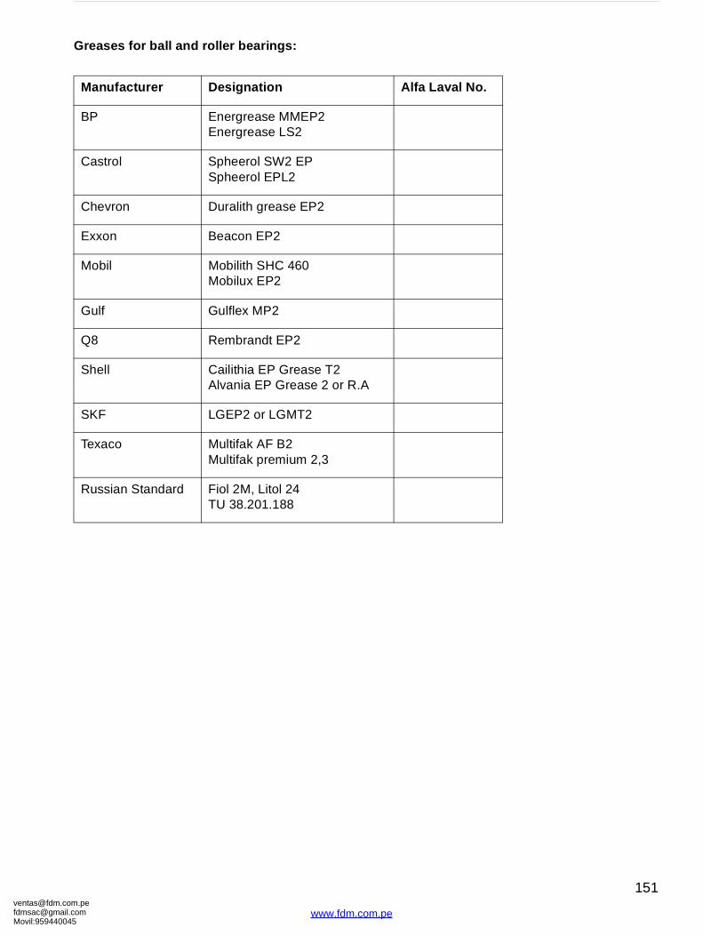
[email protected]@gmaMovil:9594400
Alfa Laval No.
Greases for ball and roller bearings:
Manufacturer Designation
BP Energrease MMEP2Energrease LS2
Castrol Spheerol SW2 EPSpheerol EPL2
Chevron Duralith grease EP2
Exxon Beacon EP2
Mobil Mobilith SHC 460Mobilux EP2
Gulf Gulflex MP2
Q8 Rembrandt EP2
Shell Cailithia EP Grease T2Alvania EP Grease 2 or R.A
SKF LGEP2 or LGMT2
Texaco Multifak AF B2Multifak premium 2,3
Russian Standard Fiol 2M, Litol 24TU 38.201.188
om.peil.com45
151
www.fdm.com.pe

ventafdmsaMovil:
oil Time in operation Oil change interval
1500 h
2000 h
S0
0324
11
Alfa Laval lube oil
8.5.4 Recommended lubricating oils
Alfa Laval ref. 553219-09
Two different groups of lubricating oils are approved. They are designated as Alfa Laval lubricating oil groups A and D which are described in ‘‘8.5.2 Alfa Laval lubricating oil groups:” on page 148.
The numerical value after the letter in the table states the viscosity grade..
The corresponding commercial oil brands are listed on next page.
Note:
• When the separator is operated for short periods, lubricating oil must be changed every 12 months even if the total number of operating hours is less than stated in the recommendations above.
• Check and prelubricate spindle bearings on separators which have been out of service for 6 months or longer.
• In seasonal operation: change oil before every operating period.
Alfa Laval do not accept responsibility for any damage caused by the use of lubricants which deviate from the recommended lubricants listed in this manual.
Ambient temperature Alfa Laval lubricating group
between +15 and +45 °C A/150
between +2 and +65 °C D/220
[email protected]@gmail.com959440045
152
www.fdm.com.pe
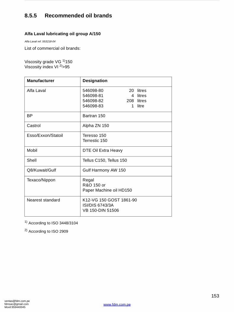
[email protected]@gmaMovil:9594400
20 litres4 litres
208 litres1 litre
0
0
150
861-90
8.5.5 Recommended oil brands
Alfa Laval lubricating oil group A/150
Alfa Laval ref. 553218-04
List of commercial oil brands:
Viscosity grade VG 1)150Viscosity index VI 2)>95
1) According to ISO 3448/3104
2) According to ISO 2909
Manufacturer Designation
Alfa Laval 546098-80546098-81546098-82546098-83
BP Bartran 150
Castrol Alpha ZN 150
Esso/Exxon/Statoil Teresso 150Terrestic 150
Mobil DTE Oil Extra Heavy
Shell Tellus C150, Tellus 15
Q8/Kuwait/Gulf Gulf Harmony AW 15
Texaco/Nippon RegalR&O 150 orPaper Machine oil HD
Nearest standard K12-VG 150 GOST 1ISI/DIS 6743/3AVB 150-DIN 51506
om.peil.com45
153
www.fdm.com.pe
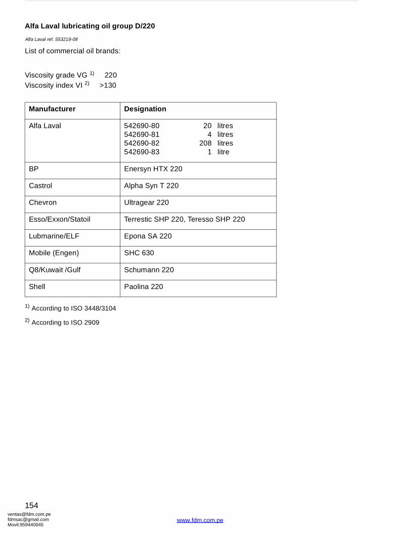
ventafdmsaMovil:
20 litres4 litres
208 litres1 litre
resso SHP 220
Alfa Laval lubricating oil group D/220
Alfa Laval ref. 553218-08
List of commercial oil brands:
Viscosity grade VG 1) 220Viscosity index VI 2) >130
1) According to ISO 3448/3104
2) According to ISO 2909
Manufacturer Designation
Alfa Laval 542690-80542690-81542690-82542690-83
BP Enersyn HTX 220
Castrol Alpha Syn T 220
Chevron Ultragear 220
Esso/Exxon/Statoil Terrestic SHP 220, Te
Lubmarine/ELF Epona SA 220
Mobile (Engen) SHC 630
Q8/Kuwait /Gulf Schumann 220
Shell Paolina 220
[email protected]@gmail.com959440045
154
www.fdm.com.pe
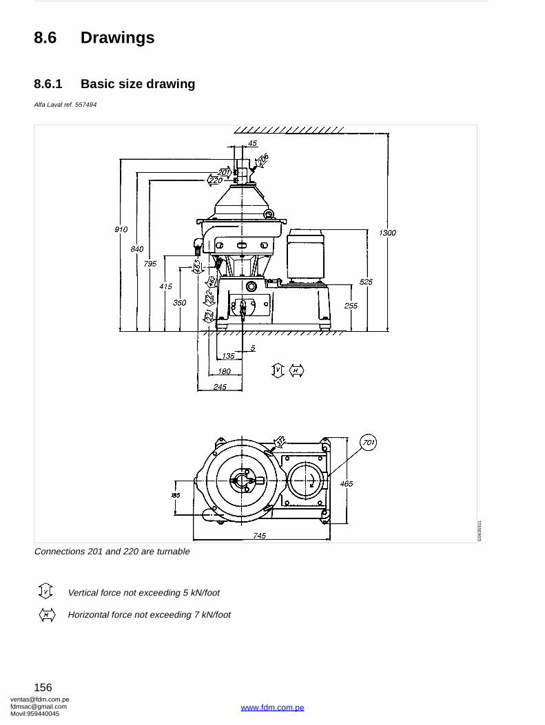
ventafdmsaMovil:
G06
3551
1
8.6 Drawings
8.6.1 Basic size drawingAlfa Laval ref. 557494
Connections 201 and 220 are turnable
Vertical force not exceeding 5 kN/foot
Horizontal force not exceeding 7 kN/foot
[email protected]@gmail.com959440045
156
www.fdm.com.pe
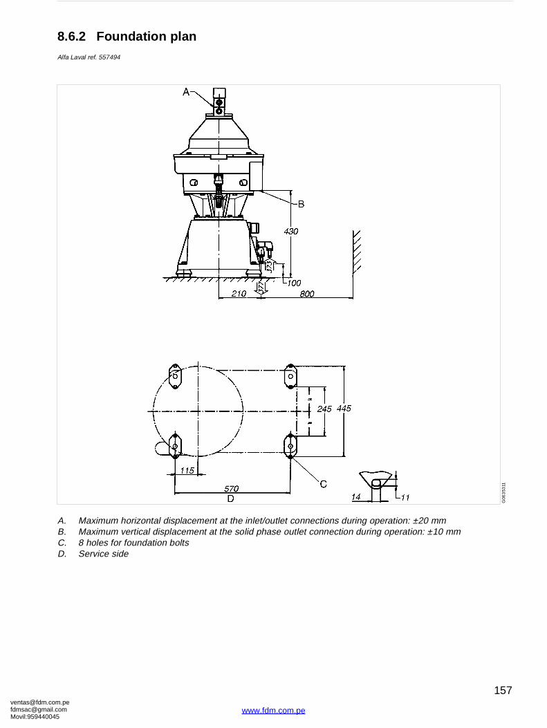
[email protected]@gmaMovil:9594400
connections during operation: ±20 mmutlet connection during operation: ±10 mm
G06
353
11
8.6.2 Foundation planAlfa Laval ref. 557494
A. Maximum horizontal displacement at the inlet/outletB. Maximum vertical displacement at the solid phase oC. 8 holes for foundation boltsD. Service side
om.peil.com45
157
www.fdm.com.pe
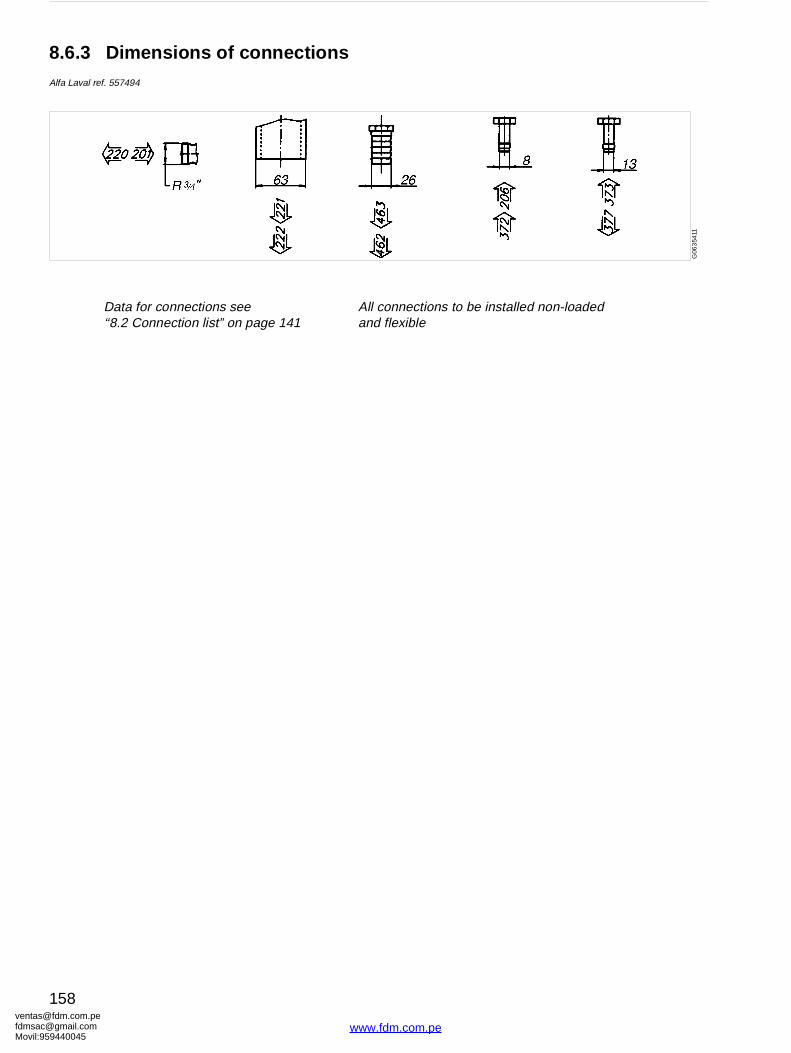
ventafdmsaMovil:
onnections to be installed non-loaded flexible
G06
354
11
8.6.3 Dimensions of connectionsAlfa Laval ref. 557494
Data for connections see ‘‘8.2 Connection list” on page 141
All cand
[email protected]@gmail.com959440045
158
www.fdm.com.pe
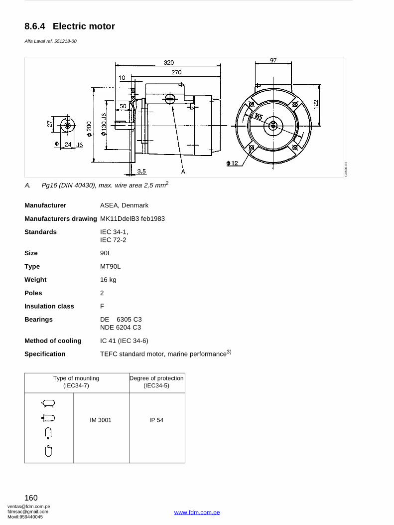
ventafdmsaMovil:
erformance3)G
0606
111
8.6.4 Electric motorAlfa Laval ref. 551218-00
Manufacturer ASEA, Denmark
Manufacturers drawing MK11DdelB3 feb1983
Standards IEC 34-1,IEC 72-2
Size 90L
Type MT90L
Weight 16 kg
Poles 2
Insulation class F
Bearings DE 6305 C3NDE 6204 C3
Method of cooling IC 41 (IEC 34-6)
Specification TEFC standard motor, marine p
Type of mounting(IEC34-7)
Degree of protection(IEC34-5)
IM 3001 IP 54
A. Pg16 (DIN 40430), max. wire area 2,5 mm2
[email protected]@gmail.com959440045
160
www.fdm.com.pe
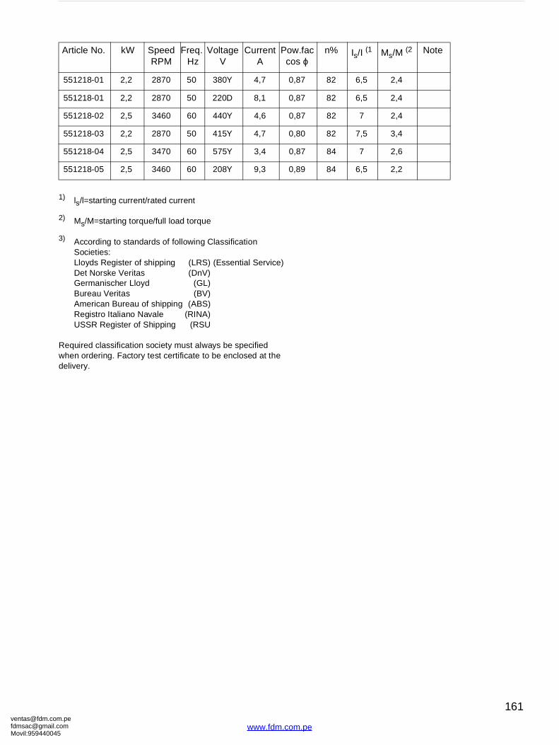
[email protected]@gmaMovil:9594400
.fac s ϕ
n% Is/I (1 Ms/M (2 Note
,87 82 6,5 2,4
,87 82 6,5 2,4
,87 82 7 2,4
,80 82 7,5 3,4
,87 84 7 2,6
,89 84 6,5 2,2
1) ls/l=starting current/rated current
2) Ms/M=starting torque/full load torque
3) According to standards of following ClassificationSocieties:Lloyds Register of shipping (LRS) (Essential Service)Det Norske Veritas (DnV)Germanischer Lloyd (GL)Bureau Veritas (BV)American Bureau of shipping (ABS)Registro Italiano Navale (RINA)USSR Register of Shipping (RSU
Required classification society must always be specified when ordering. Factory test certificate to be enclosed at the delivery.
Article No. kW Speed RPM
Freq. Hz
Voltage V
Current A
Powco
551218-01 2,2 2870 50 380Y 4,7 0
551218-01 2,2 2870 50 220D 8,1 0
551218-02 2,5 3460 60 440Y 4,6 0
551218-03 2,2 2870 50 415Y 4,7 0
551218-04 2,5 3470 60 575Y 3,4 0
551218-05 2,5 3460 60 208Y 9,3 0
om.peil.com45
161
www.fdm.com.pe
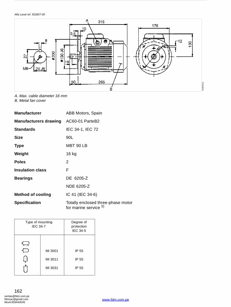
ventafdmsaMovil:
ase motor G
060
621
1
Alfa Laval ref. 552807-00
Manufacturer ABB Motors, Spain
Manufacturers drawing AC60-01 ParteB2
Standards IEC 34-1, IEC 72
Size 90L
Type MBT 90 LB
Weight 16 kg
Poles 2
Insulation class F
Bearings DE 6205-Z
NDE 6205-Z
Method of cooling IC 41 (IEC 34-6)
Specification Totally enclosed three-phfor marine service 3)
Type of mountingIEC 34-7
Degree of protectionIEC 34-5
IM 3001
IM 3011
IM 3031
IP 55
IP 55
IP 55
A. Max. cable diameter 16 mmB. Metal fan cover
[email protected]@gmail.com959440045
162
www.fdm.com.pe
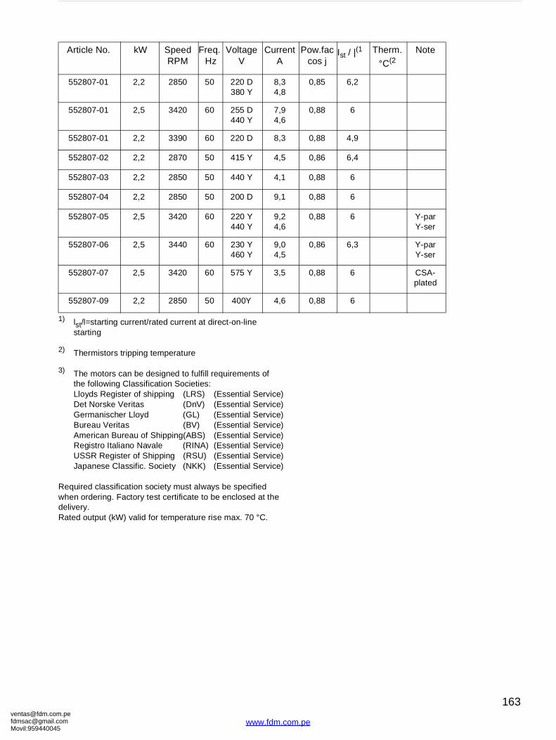
[email protected]@gmaMovil:9594400
t Pow.fac cos j
Ist / |(1 Therm.
°C(2
Note
0,85 6,2
0,88 6
0,88 4,9
0,86 6,4
0,88 6
0,88 6
0,88 6 Y-parY-ser
0,86 6,3 Y-parY-ser
0,88 6 CSA- plated
0,88 6
1) lst/l=starting current/rated current at direct-on-linestarting
2) Thermistors tripping temperature
3) The motors can be designed to fulfill requirements ofthe following Classification Societies:Lloyds Register of shipping (LRS) (Essential Service)Det Norske Veritas (DnV) (Essential Service)Germanischer Lloyd (GL) (Essential Service)Bureau Veritas (BV) (Essential Service)American Bureau of Shipping(ABS) (Essential Service)Registro Italiano Navale (RINA) (Essential Service)USSR Register of Shipping (RSU) (Essential Service)Japanese Classific. Society (NKK) (Essential Service)
Required classification society must always be specified when ordering. Factory test certificate to be enclosed at the delivery.Rated output (kW) valid for temperature rise max. 70 °C.
Article No. kW Speed RPM
Freq. Hz
Voltage V
CurrenA
552807-01 2,2 2850 50 220 D380 Y
8,34,8
552807-01 2,5 3420 60 255 D440 Y
7,94,6
552807-01 2,2 3390 60 220 D 8,3
552807-02 2,2 2870 50 415 Y 4,5
552807-03 2,2 2850 50 440 Y 4,1
552807-04 2,2 2850 50 200 D 9,1
552807-05 2,5 3420 60 220 Y440 Y
9,24,6
552807-06 2,5 3440 60 230 Y460 Y
9,04,5
552807-07 2,5 3420 60 575 Y 3,5
552807-09 2,2 2850 50 400Y 4,6
om.peil.com45
163
www.fdm.com.pe
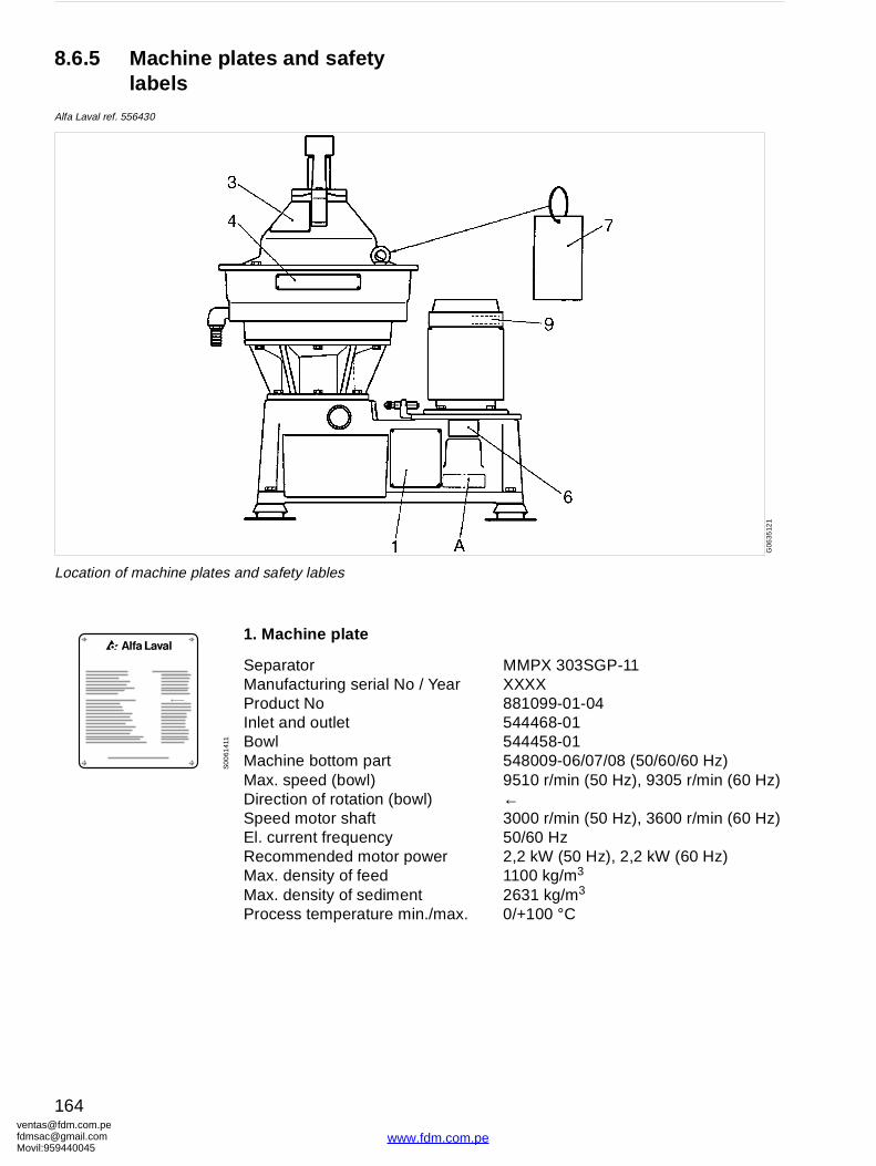
ventafdmsaMovil:
Year
l)
er
./max.
MMPX 303SGP-11XXXX881099-01-04544468-01544458-01548009-06/07/08 (50/60/60 Hz)9510 r/min (50 Hz), 9305 r/min (60 Hz)←3000 r/min (50 Hz), 3600 r/min (60 Hz)50/60 Hz2,2 kW (50 Hz), 2,2 kW (60 Hz)1100 kg/m3
2631 kg/m3
0/+100 °C
G06
3512
1
8.6.5 Machine plates and safety labels
Alfa Laval ref. 556430
1. Machine plate
SeparatorManufacturing serial No /Product NoInlet and outletBowlMachine bottom partMax. speed (bowl)Direction of rotation (bowSpeed motor shaftEl. current frequencyRecommended motor powMax. density of feedMax. density of sedimentProcess temperature min
Location of machine plates and safety lables
S0
061
411
[email protected]@gmail.com959440045
164
www.fdm.com.pe

[email protected]@gmaMovil:9594400
S0
061
521
S0
0632
11
50Hz
60Hz
S0
063
111
3. Safety label
Text on label:
DANGER
Read the instruction manuals before installation, operation and maintenance. Consider inspection intervals.
Failure to strictly follow instructions can lead to fatal injury.
If excessive vibration occur, stop separator and keep bowl filled with liquid during rundown.
Out of balance vibration will become worse if bowl is not full.
Separator must stop rotating before any dismantling work is started.
4. Name plate
6. Power supply frequency
7. Label
Text on label:
Read the instruction manual before lifting.
9. Space for additional label as specified in the order
A. Space for label indicating representative
om.peil.com45
165
www.fdm.com.pe

ventafdmsaMovil:
G00
749
31
Gravity disc hole diameter, φ mm
8.6.6 Gravity disc nomogram
Oil density, kg/m3 at 15 oC
[email protected]@gmail.com959440045
166
www.fdm.com.pe
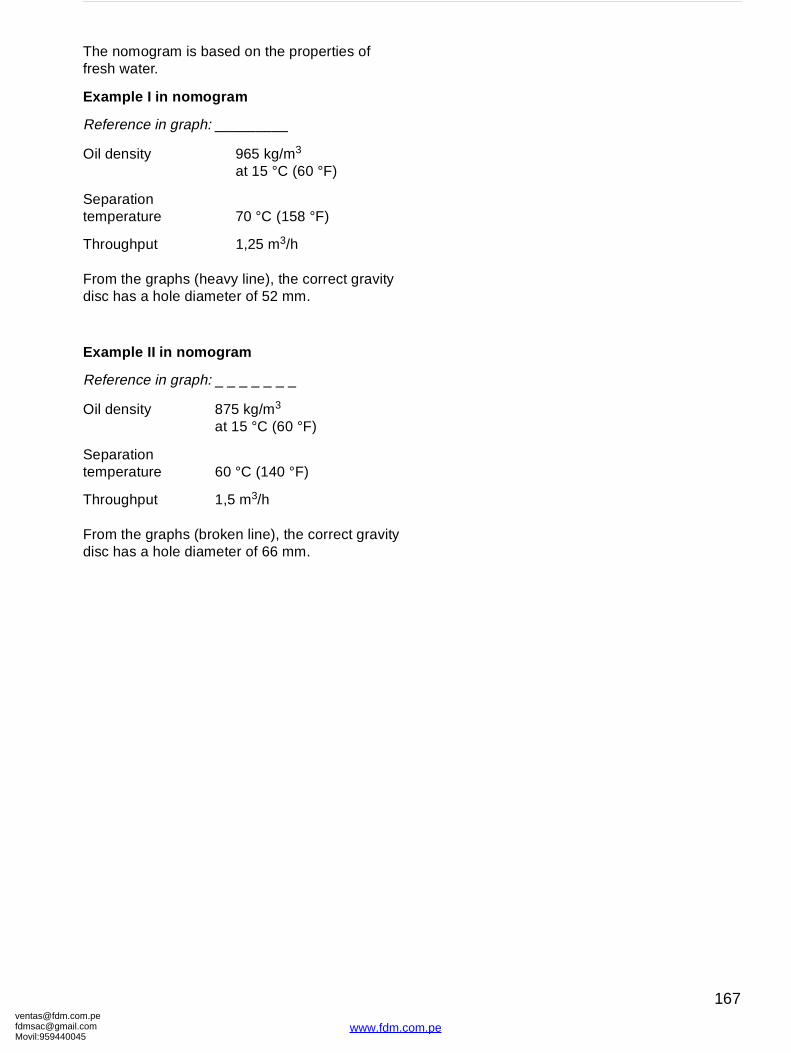
[email protected]@gmaMovil:9594400
The nomogram is based on the properties of fresh water.
Example I in nomogram
Reference in graph: _________
From the graphs (heavy line), the correct gravity disc has a hole diameter of 52 mm.
Example II in nomogram
Reference in graph: _ _ _ _ _ _ _
From the graphs (broken line), the correct gravity disc has a hole diameter of 66 mm.
Oil density 965 kg/m3 at 15 °C (60 °F)
Separation temperature 70 °C (158 °F)
Throughput 1,25 m3/h
Oil density 875 kg/m3 at 15 °C (60 °F)
Separation temperature 60 °C (140 °F)
Throughput 1,5 m3/h
om.peil.com45
167
www.fdm.com.pe
ventafdmsaMovil:
8.7 Storage and installation
8.7.1 Storage and transport of goods
Storage
Specification
Upon arrival to the store, check all components and keep them:
1. Well stored and protected from mechanical damage and theft.
2. Dry an protected from rain and humidity
3. Organized in the store in such a way that the goods will be easily accessible when installation is about to take place.
[email protected]@gmail.com959440045
168
www.fdm.com.pe
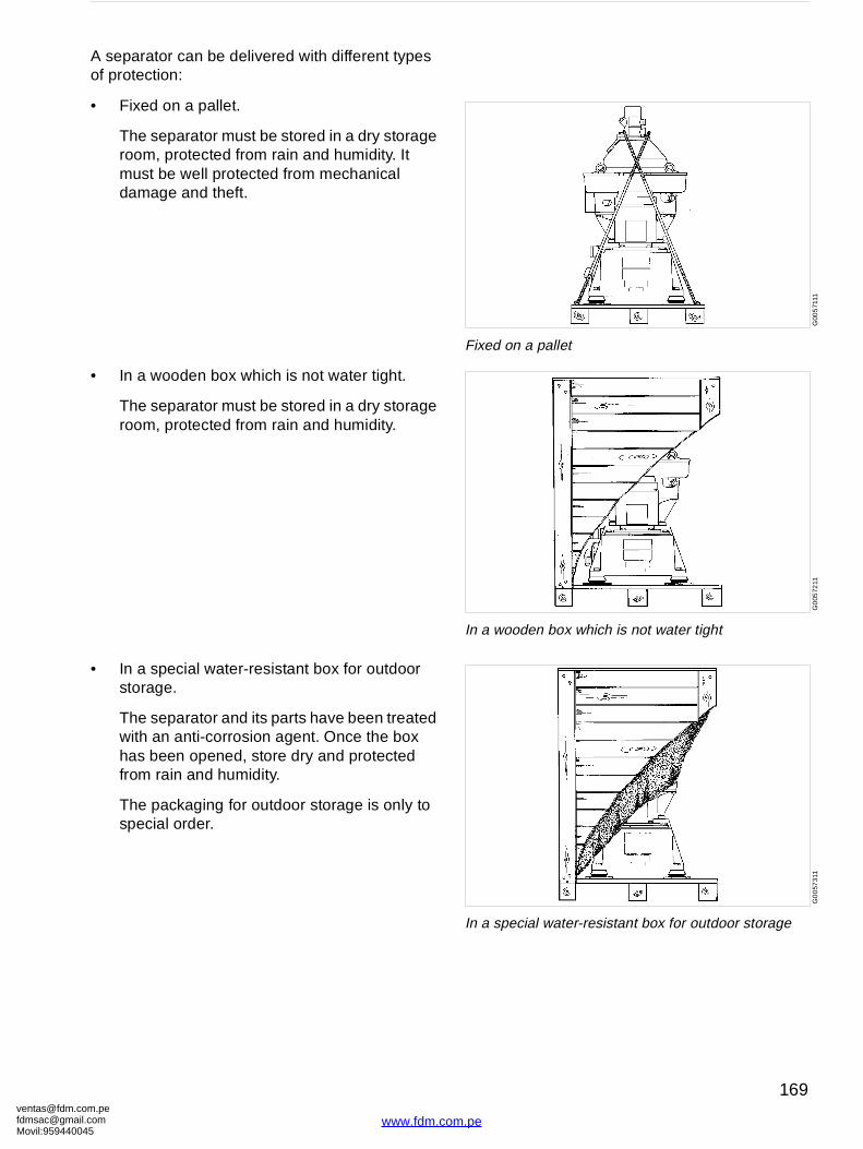
[email protected]@gmaMovil:9594400
G00
571
11
Fixed on a pallet
G0
0572
11
In a wooden box which is not water tight
G0
057
311
In a special water-resistant box for outdoor storage
A separator can be delivered with different types of protection:
• Fixed on a pallet.
The separator must be stored in a dry storage room, protected from rain and humidity. It must be well protected from mechanical damage and theft.
• In a wooden box which is not water tight.
The separator must be stored in a dry storage room, protected from rain and humidity.
• In a special water-resistant box for outdoor storage.
The separator and its parts have been treated with an anti-corrosion agent. Once the box has been opened, store dry and protected from rain and humidity.
The packaging for outdoor storage is only to special order.
om.peil.com45
169
www.fdm.com.pe
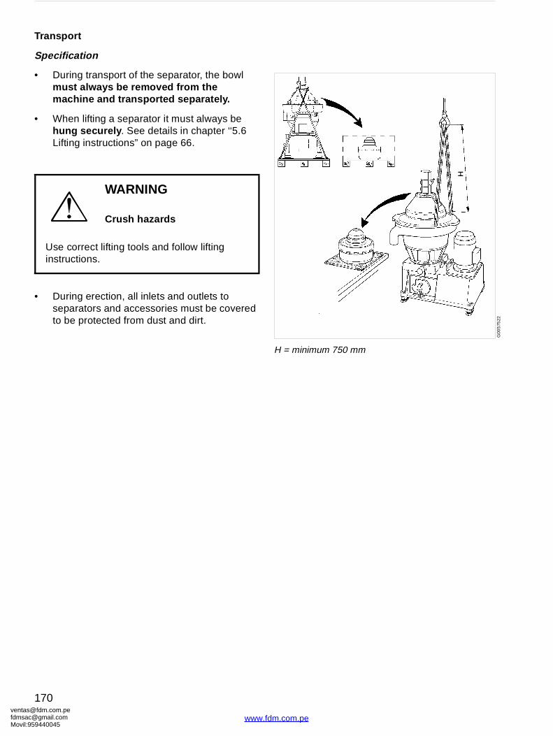
ventafdmsaMovil:
G00
575
22
H = minimum 750 mm
Transport
Specification
• During transport of the separator, the bowl must always be removed from the machine and transported separately.
• When lifting a separator it must always be hung securely . See details in chapter ‘‘5.6 Lifting instructions” on page 66.
• During erection, all inlets and outlets to separators and accessories must be covered to be protected from dust and dirt.
WARNING
Crush hazards
Use correct lifting tools and follow lifting instructions.
[email protected]@gmail.com959440045
170
www.fdm.com.pe

[email protected]@gmaMovil:9594400
G0
020
611
Check the drawings when planning the installation
G00
2072
1
Suitable space must be obtained for the maintenance work
8.7.2 Planning of installation
Introduction
The space required for one or more separators can be calculated by consulting ‘‘8.6.1 Basic size drawing” on page 156, and instructions for ancillary equipment, electrical and electronic equipment and cables.
Important measurements
Important measurements are the minimum lifting height for lifting tackle, shortest distance between driving motor and wall, free passage for dismantling and assembly, maintenance and operation.
Plan your installation with sufficient room for the controls and operation so that instruments are easily visible. Valves and controls must be within convenient reach. Pay attention to space requirements for maintenance work, work benches, dismantled machine parts or for a service trolley.
Space for separator
The separator shall be placed in such a way that suitable space for maintenance and repair is obtained.
Specification
See the ‘‘8.6.2 Foundation plan” on page 157 for the service space required with the separator installed.
Recommendation
The spanner for the bowl hood should have sufficient space to make a complete turn without touching any of the ancillary equipment surrounding the separator.
om.peil.com45
171
www.fdm.com.pe
ventafdmsaMovil:
Lifting height for transport of bowl
Specification
A minimum height is required to lift the bowl, bowl parts and the bowl spindle, see the drawing ‘‘8.6.2 Foundation plan” on page 157.
Recommendation
When two or more separators are installed, the lifting height may have to be increased to enable parts from one separator to be lifted and moved over an adjoining assembled separator.
Space for oil changing
Specification
The oil filling device must not be blocked by floor plate arrangement, etc.
Recommendation
It should be possible to place a portable collecting tray under the oil filling device drain hole.
8.7.3 Foundations
Specification
• The separator should be installed at floor level, see ‘‘8.6.2 Foundation plan” on page 157.
• The separator must be installed on a strong and rigid foundation to reduce the influence of vibrations from adjacent machinery.
• The foundation should be provided with a cofferdam.
NOTE
When lifting a separator it must always be hung securely . See the separate lifting instruction in this book.
[email protected]@gmail.com959440045
172
www.fdm.com.pe

[email protected]@gmaMovil:9594400
• Fit the separator frame on the foundation as follows:
− Check that the bolts do not press against the edges of the holes, otherwise the elasticity of the mounting of the separator frame will be impeded.
− Fit height adjusting washers required.
− Check that the separator frame is horizontal and that all feet rest on the foundation.
− Tighten the screws.
om.peil.com45
173
www.fdm.com.pe
[email protected]@gmaMovil:9594400
e manuals as possible. Should you have any ual, please note them down and send them to g it by fax, or you could mail it, or hand it over
SKL, S-147 80 Tumba, Sweden.
Company:
City:
Book No.: 1270065-02 V2
Yes No
e table of contents? ❒ ❒
quate? ❒ ❒
your purposes? ❒ ❒
s? ❒ ❒
al? ❒ ❒
❒ ❒
❒ ❒
Reader’s Comment Form
Dear reader,
It is our ambition to produce as useful and instructivcomments (positive or negative) regarding this manus. You can do this by copying this page and sendinto your local Alfa Laval representative.
Alfa Laval Separation AB, Separator Manuals, dept.Fax: +46 8 53065029.
Your name:
Address:
Country:
Product: MMPX 303SGP-11
Date:
Is it easy to find what you are looking for by using th
Are the chapter and section headings clear and ade
Is the information presented in the correct order for
Does the information in the manual cover your need
Is it easy to understand the instructions in the manu
Is the terminology sufficiently explained?
Are the illustrations easy to understand?
Your comments:
om.peil.com45
175
www.fdm.com.pe
[email protected]@gmaMovil:9594400
se copy this page and give it to your local rent prices.
to help you with information regarding any
Company:
City:
Book No.: 1270065-02 V2
Date:
Order Form
If you wish to order extra copies of this manual, pleaAlfa Laval representative, who will advise you of cur
Your local Alfa Laval representative will also be ableother manuals.
Your name:
Address:
Country:
Product: MMPX 303SGP-11
Quantity:
Comments:
om.peil.com45
177
www.fdm.com.pe
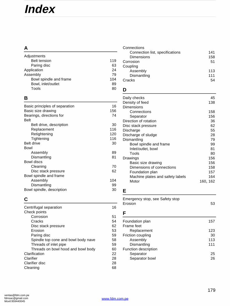
[email protected]@gmaMovil:9594400
Index
A
AdjustmentsBelt tension 119Paring disc 63
Application 24Assembly 79
Bowl spindle and frame 104Bowl, inlet/outlet 89Tools 80
B
Basic principles of separation 16Basic size drawing 156Bearings, directions for 74Belt
Belt drive, description 30Replacement 116Retightening 120Tightening 116
Belt drive 30Bowl
Assembly 89Dismantling 81
Bowl discsCleaning 70Disc stack pressure 62
Bowl spindle and frameAssembly 104Dismantling 99
Bowl spindle, description 30
C
Centrifugal separation 16Check points
Corrosion 51Cracks 54Disc stack pressure 62Erosion 53Paring disc 59Spindle top cone and bowl body nave 58Threads of inlet pipe 59Threads on bowl hood and bowl body 60
Clarification 22Clarifier 28Clarifier disc 28Cleaning 68
ConnectionsConnection list, specifications 141Dimensions 158
Corrosion 51Coupling
Assembly 113Dismantling 111
Cracks 54
D
Daily checks 45Density of feed 138Dimensions
Connections 158Separator 156
Direction of rotation 36Disc stack pressure 62Discharge 55Discharge of sludge 28Dismantling 79
Bowl spindle and frame 99Inlet/outlet, bowl 81Tools 80
Drawings 156Basic size drawing 156Dimensions of connections 158Foundation plan 157Machine plates and safety labels 164Motor 160, 162
E
Emergency stop, see Safety stopErosion 53
F
Foundation plan 157Frame feet
Replacement 123Friction coupling 30
Assembly 113Dismantling 111
Function descriptionSeparator 25Separator bowl 26
om.peil.com45
179
www.fdm.com.pe
ventafdmsaMovil:
G
Gravity 27Gravity disc
Nomogram 166Selection 34
Gravity disc, purification 27Greases, lubricants 150
I
Inlet/outletAssembly 98Dismantling 81
Inspection slot, bowl hood 36Installation 168Installation planning 171Interface to other equipment, description 143
L
Lifting instructions 66Lubrication
Lubricants, greases 150Lubrication chart 147
M
Machine plates 164Maintenance
Intervals 42Procedure 44
Materials 140Motor 144, 160, 162Motor current at start 38
N
Noise 130
O
Oil discharge through water outlet 136Oil filling device
Exploded view 121Oil sump
Lubricating oils 148Oil change interval 46Oil change procedure 71Recommended lubricating oils/brands 152Volume 139
Operation 33
P
Periodic maintenance 42Power consumption 138
Power transmission, mechanicalBelt drive 30Bowl spindle 30Friction coupling 30
Purification 20Purifier bowl
Characteristic parts 20
R
Recommended oil brands 153Rotation, direction 36
S
Safety Instructions 9Safety labels 164Safety stop 40Separation result, unsatisfactory 136Separation, basic principles 16Separator does not start 126Separator vibrates 129Service intervals 42Service kits 44Service logs 47, 49Shut-downs 77Sliding bowl bottom 28, 56Sludge 28Smell 130Speed 139
Speed too high 130Start 34, 35, 37
Separator vibrates 128Starting power too high 127Starting power too low 126Start-up period 38, 139Start-up time too long 126
StopSafety stop 40Stopping procedure 38Stopping time 139
Storage 168
T
Technical data 138Tools 80Transport of separator 170Trouble-tracing 125
V
VibrationDuring start 37Safety stop 40
[email protected]@gmail.com959440045
180
www.fdm.com.pe
[email protected]@gmaMovil:9594400
W
Warning signs 13Water
Water quality specifications 146
om.peil.com45
181
www.fdm.com.pe


![Untitled Document [fdm.com.pe]fdm.com.pe/wp-content/uploads/2018/11/ALFA-LAVAL-Repuestos-MMPX303.pdfNão esqueça que Alfa Laval não aceita responsabilidade por falha de uma separadora](https://img.dokumen.tips/doc/110x75/60dacaf56f149a6a0670ba7e/untitled-document-fdmcompefdmcompewp-contentuploads201811alfa-laval-repuestos-.jpg)