Embed Size (px)
Citation preview

[email protected]@gmail.comMovil:959440045
MAB 103B-24
Separator Manual
High Speed Separator
Product No. 881145-09-01/7�Book No. 1270118-02 Rev. 7 www.fdm.com.pe

[email protected]@gmail.comMovil:959440045
2
Published By:Alfa Laval Tumba AB�SE-147 80 Tumba, Sweden
Telephone: +46 8 530 650 00�Telefax:+46 8 530 310 40
© Alfa Laval Tumba AB 13 August 2008
This publication or any part there of may not be reproduced or transmitted by any process or means without prior written permission of Alfa Laval Tumba AB.
www.fdm.com.pe

[email protected]@gmail.comMovil:959440045
Contents
3
1 Read this first 7
2 Safety Instructions 9
2.1 Warning signs in text 14
2.2 Environmental issues 15
2.3 Requirements of personnel 16
3 Separator Basics 17
3.1 Basic principles of separation 18
3.2 Overview 21
3.3 Separating function 22
3.4 Mechanical function 25
3.5 Definitions 29
4 Operating Instructions 31
4.1 Operating routine 32
4.2 Cleaning the bowl 39
5 Service Instructions 45
5.1 Periodic Maintenance 46
5.2 Maintenance Logs 48
5.3 MS - Check points 54
5.4 Cleaning 68
5.5 When changing oil 72
5.6 Common maintenance directions 74
5.7 Lifting instructions 79
6 Dismantling/Assembly 81
6.1 General 82
6.2 Dismantling 83
6.3 Assembly 93
www.fdm.com.pe

[email protected]@gmail.comMovil:959440045
4
6.4 Feed and discharge pumps 101
6.5 Oil filling 106
6.6 Brake 107
6.7 Frame feet 108
7 Trouble-tracing 109
7.1 Trouble tracing procedure 110
7.2 MAB mechanical function 110
7.3 Purification faults 116
7.4 Clarification faults 118
8 Technical Reference 119
8.1 Product description 120
8.2 Technical data 121
8.3 Basic size drawing 126
8.4 Basic size drawing, for heater 128
8.5 Connection list 130
8.6 Connection list, for heater 131
8.7 Interface description 132
8.8 Lubricants 135
8.9 Drawings 148
8.10 Lock switch 160
8.11 Storage and installation 164
Index 175
www.fdm.com.pe

[email protected]@gmail.comMovil:959440045
5
Read and understand instruction manuals and observe the warnings before installation, operation, service and maintenance.
Not following the instructions can result in serious accidents.
In order to make the information clear only foreseeable conditions have been considered. No warnings are given, therefore, for situations arising from the unintended usage of the machine and its tools.
www.fdm.com.pe

[email protected]@gmail.comMovil:959440045
7
1 Read this first
This manual is designed for operators and service engineers working with the Alfa Laval separator MAB 103B-24.
For information concerning the function of the separator, see ‘‘3 Separator Basics” on page 17, and ‘‘4 Operating Instructions” on page 31.
If the separator has been delivered and installed by Alfa Laval as part of a processing system, this manual is a part of the System Manual. In this case, study carefully all the instructions in the System Manual.
In addition to this Separator Manual a Spare Parts Catalogue, SPC is supplied.
This Separator Manual consists of:
Safety Instructions
Pay special attention to the safety instructions for the separator. Not following the safety instructions can cause accidents resulting in damage to equipment and serious injury to personnel.
Separator Basics
Read this chapter if you are not familiar with this type of separator.
Operating Instructions
This chapter contains operating instructions for the separator only.
S00
6801
1
Separator Manual and Spare Parts Catalogue
www.fdm.com.pe

[email protected]@gmail.comMovil:959440045
1 Read this first
8
Service Instructions
This chapter gives instructions for daily checks, cleaning, oil changes, servicing and check points.
Dismantling / Assembly
This chapter contains step-by-step instructions for dismantling and assembly of the separator for service and repair.
Trouble-tracing
Refer to this chapter if the separator functions abnormally.
If the separator has been installed as part of a processing system always refer to the Trouble-tracing part of the System Manual first.
Technical Reference
This chapter contains technical data concerning the separator and drawings.
Installation
General information on installation planning.
Lifting instruction.
Index
This chapter contains an alphabetical list of subjects, with page references.
www.fdm.com.pe

[email protected]@gmail.comMovil:959440045
9
2 Safety Instructions
The centrifuge includes parts that rotate at high speed. This means that:
� Kinetic energy is high
� Great forces are generated
� Stopping time is long
Manufacturing tolerances are extremely fine. Rotating parts are carefully balanced to reduce undesired vibrations that can cause a breakdown. Material properties have been considered carefully during design to withstand stress and fatigue.
The separator is designed and supplied for a specific separation duty (type of liquid, rotational speed, temperature, density etc.) and must not be used for any other purpose.
Incorrect operation and maintenance can result in unbalance due to build-up of sediment, reduction of material strength, etc., that subsequently could lead to serious damage and/or injury.
The following basic safety instructions therefore apply:
� Use the separator only for the purpose and parameter range specified by Alfa Laval.
� Strictly follow the instructions for installation, operation and maintenance.
� Ensure that personnel are competent and have sufficient knowledge of maintenance and operation, especially concerning emergency stopping procedures.
� Use only Alfa Laval genuine spare parts and the special tools supplied.
G00
1042
1S
0151
211
www.fdm.com.pe

[email protected]@gmail.comMovil:959440045
2 Safety Instructions
10
Disintegration hazards
� When power cables are connected, always check direction of motor rotation. If incorrect, vital rotating parts could unscrew.
� If excessive vibration occurs, stop separator and keep bowl filled with liquid during rundown.
� Use the separator only for the purpose and parameter range specified by Alfa Laval.��
� Check that the gear ratio is correct for power frequency used. If incorrect, subsequent overspeed may result in a serious break down.
� Welding or heating of parts that rotate can seriously affect material strength.
� Wear on the large lock ring thread must not exceed safety limit. �-mark on lock ring must not pass opposite �-mark by more than specified distance.�
� Inspect regularly for corrosion and erosion damage. Inspect frequently if process liquid is corrosive or erosive.
S01
512F
1S
0151
2N1
S01
512P
1S
0151
2L1
S01
5124
1S
0151
2G1
S01
512H
1
www.fdm.com.pe

[email protected]@gmail.comMovil:959440045
11
2 Safety Instructions
Entrapment hazards
� Make sure that rotating parts have come to a complete standstill before starting any dismantling work.����
� To avoid accidental start, switch off and lock power supply before starting any dismantling work.��Assemble the machine completely before start. All covers and guards must be in place.
�
�
Electrical hazard
� Follow local regulations for electrical installation and earthing (grounding).
� To avoid accidental start, switch off and lock power supply before starting any dismantling work.
Crush hazards
� Use correct lifting tools and follow lifting instructions.�����Do not work under a hanging load.
S01
512O
1S
0151
261
S01
5127
1S
0151
2M1
S01
512Y
1
www.fdm.com.pe

[email protected]@gmail.comMovil:959440045
2 Safety Instructions
12
Noise hazards
� Use ear protection in noisy environments.
Burn hazards
� Lubrication oil and various machine surfaces can be hot and cause burns.
Skin irritation hazards
� When using chemical cleaning agents, make sure you follow the general rules and suppliers recommendation regarding ventilation, personnel protection etc.
� Use of lubricants in various situations.
S01
5129
1S
0151
2A1
S01
512D
1
www.fdm.com.pe

[email protected]@gmail.comMovil:959440045
13
2 Safety Instructions
Cut hazards
� Sharp edges on bowl discs and threads can cause cuts.
Flying objects
� Risk for accidental release of snap rings and springs when dismantling and assembly.
Health hazard
� Risk for unhealthy dust when handling friction blocks/pads. Use a dust mask to make sure not to inhale any dust.
S01
512B
1S
0151
2C1
S01
512V
1
www.fdm.com.pe

[email protected]@gmail.comMovil:959440045
2 Safety Instructions
14
2.1 Warning signs in textPay attention to the safety instructions in this manual. Below are definitions of the three grades of warning signs used in the text where there is a risk for injury to personnel.
DANGER
Type of hazard
DANGER indicates an imminently hazardous situation which, if not avoided, will result in death or serious injury.
WARNING
Type of hazard
WARNING indicates a potentially hazardous situation which, if not avoided, could result in death or serious injury.
CAUTION
Type of hazard
CAUTION indicates a potentially hazardous situation which, if not avoided, may result in minor or moderate injury.
NOTE
NOTE indicates a potentially hazardous situation which, if not avoided, may result in property damage.
www.fdm.com.pe

[email protected]@gmail.comMovil:959440045
15
2 Safety Instructions
2.2 Environmental issues
Unpacking
Packing material consists of wood, plastics, cardboard boxes and in some cases metal straps.
Wood and cardboard boxes can be reused, recycled or used for energy recovery.
Plastics should be recycled or burnt at a licensed waste incineration plant.
Metal straps should be sent for material recycling.
Maintenance
During maintenance oil and wear parts in the machine are replaced.
Oil must be taken care of in agreement with local regulations.
Rubber and plastics should be burnt at a licensed waste incineration plant. If not available they should be disposed to a suitable licensed land fill site.
Bearings and other metal parts should be sent to a licensed handler for material recycling.
Seal rings and friction linings should be disposed to a licensed land fill site. Check your local regulations.
Worn out or defected electronic parts should be sent to a licensed handler for material recycling.
www.fdm.com.pe

[email protected]@gmail.comMovil:959440045
2 Safety Instructions
16
2.3 Requirements of personnel
Only skilled or instructed persons are allowed to operate the machine, e.g. operating and maintenance staff.
� Skilled person: A person with technical knowledge or sufficient experience to enable him or her to perceive risks and to avoid hazards which electricity/mechanics can create.
� Instructed person: A person adequately advised or supervised by a skilled person to enable him or her to perceive risks and to avoid hazards which electricity/mechanics can create.
In some cases special skilled personnel may need to be hired, like electricians and others. In some of these cases the personnel has to be certified according to local regulations with experience of similar types of work.
www.fdm.com.pe

[email protected]@gmail.comMovil:959440045
17
3 Separator Basics
Contents
3.1 Basic principles of separation 18
3.1.1 Factors influencing the�separation result 19
3.2 Overview 21
3.3 Separating function 22
3.3.1 Purifier bowl 22
3.3.2 Position of interface - gravity disc 23
3.3.3 Clarifier bowl 24
3.4 Mechanical function 25
3.4.1 Inlet and outlet 25
3.4.2 Mechanical power transmission 26
3.4.3 Brake 27
3.4.4 Inlet and outlet pump 27
3.4.5 Sensors and indicators 28
3.5 Definitions 29
www.fdm.com.pe

[email protected]@gmail.comMovil:959440045
3.1 Basic principles of separation 3 Separator Basics
18
3.1 Basic principles of separation
The purpose of separation can be:
� to free a liquid of solid particles,
� to separate two mutually insoluble liquids with different densities while removing any solids presents at the same time,
� to separate and concentrate solid particles from a liquid.
Separation by gravity
A liquid mixture in a stationary bowl will clear slowly as the heavy particles in the liquid mixture sink to the bottom under the influence of gravity.
A lighter liquid rises while a heavier liquid and solids sink.
Continuous separation and sedimentation can be achieved in a settling tank having outlets arranged according to the difference in density of the liquids.
Heavier particles in the liquid mixture will settle and form a sediment layer on the tank bottom
Centrifugal separation
In a rapidly rotating bowl, the force of gravity is replaced by centrifugal force, which can be thousands of times greater.
Separation and sedimentation is continuous and happens very quickly.
The centrifugal force in the separator bowl can achieve in a few seconds what takes many hours in a tank under influence of gravity.
G00
1071
1
Sedimentation by gravity
G00
1081
1
Sedimentation in a settling tank, with outlets making it possible to separate the lighter liquid parts from the heavier
G00
1091
1
The centrifugal solution
www.fdm.com.pe

[email protected]@gmail.comMovil:959440045
19
3 Separator Basics 3.1 Basic principles of separation
3.1.1 Factors influencing the separation result
Separating temperature
For some types of process liquids (e.g. mineral oils) a high separating temperature will normally increase the separation capacity. The temperature influences oil viscosity and density and should be kept constant throughout the separation.
Viscosity
Low viscosity facilitates separation. Viscosity can be reduced by heating.
Density difference (specific gravity ratio)
The greater the density difference between the two liquids, the easier the separation. The density difference can be increased by heating.
G00
1101
1
High viscosity (with low temperature)
G00
1111
1
Low viscosity (with high temperature)
G00
1121
1
High density (with low temperature)
G00
1131
1
Low density (with high temperature)
www.fdm.com.pe

[email protected]@gmail.comMovil:959440045
3.1 Basic principles of separation 3 Separator Basics
20
Phase proportions
An increased quantity of water in a oil will influence the separating result through the optimum transporting capacity of the disc stack. �An increased water content in the oil can be compensated by reducing the throughput in order to restore the optimum separating efficiency.
The throughput
The throughput sets the time allowed for the separation of water and sediment from the oil. A better separation result can often be achieved by reducing the throughput, i.e. by increasing the settling time.
Sludge space - sludge content
Sediment will accumulate on the inside periphery of the bowl. When the sludge space is filled up the flow inside the bowl is influenced by the sediment and thereby reducing the separating efficiency. In such cases the time between cleaning should be reduced to suit these conditions.
Disc stack
A neglected disc stack containing deformed discs or discs coated with deposits will impair the separating result.
G06
0121
1
Sludge accumulation
www.fdm.com.pe

[email protected]@gmail.comMovil:959440045
21
3 Separator Basics 3.2 Overview
3.2 OverviewThe separator comprises a processing part and a driving part. It is driven by an electric motor (6).
Mechanically, the separator machine frame is composed of a bottom part, a top part and a collecting cover. The motor is flanged to the frame as shown in the illustration. The frame feet have vibration damping.
The bottom part of the separator contains the horizontal driving device (1), driving shaft with couplings, a worm gear and a vertical spindle.
The bottom part also contains an oil bath for the worm gear, a brake and a revolution counter, indicating speed.
A pump (3) is attached to the driving spindle and located on the side of the bottom part. This pump has dual function. It is the feed inlet pump and the clean oil discharge pump.
The frame top part and the collecting cover contain the processing parts of the separator, the inlet and outlets and piping.
The liquid is cleaned in the separator bowl (4). This is fitted on the upper part of the vertical spindle and rotates at high speed inside the space formed by the frame top part and collecting cover.
The main inlets and outlets are shown with connection numbers in the illustration. These numbers correspond with the numbers used in the connection list and the basic size drawing which can be found in chapter ‘‘8 Technical Reference” on page 119.
G05
8841
1
1. Horizontal driving device, friction coupling�and worm gear
2. Collecting cover.3. Inlet and outlet gear pump4. Separator bowl5. Inlet / outlet6. Electric motor
G05
9961
1
Inlet and outlet connections
www.fdm.com.pe

[email protected]@gmail.comMovil:959440045
3.3 Separating function 3 Separator Basics
22
3.3 Separating functionUnseparated oil is fed into the bowl through the inlet pipe and is pumped via the distributor towards the periphery of the bowl.
When the oil reaches holes of the distributor, it will rise through the channels formed by the disc stack where it is evenly distributed.
The oil is continuously cleaned as it flows towards the center of the bowl. When the cleaned oil leaves the disc stack it rises upwards, flows over the gravity disc and leaves the bowl through outlet (220). Separated water, sludge and solid particles are forced towards the periphery of the bowl and collected in the sludge space.
The space between bowl hood and top disc are normally filled with water.
3.3.1 Purifier bowl
The illustration shows characteristic parts of the purifier bowl:
1. Top disc with neck
2. The gravity disc, which should be chosen according to directions in chapter ‘‘4.1.2 Selection of gravity disc” on page 32.
This bowl has two liquid outlets. The process liquid flows through the distributor to the interspaces between the bowl discs, where the liquid phases are separated from each other by action of the centrifugal force. The heavy phase and any solids move along the underside of the bowl discs towards the periphery of the bowl, where the solids settle on the bowl wall.
The heavy phase flows along the upper side of the top disc towards the neck of the bowl hood and leaves the bowl via the gravity disc the outer way.
The light phase flows along the upper side of the bowl discs towards the bowl centre and leaves the bowl via the hole in the top disc neck the inner way.
G06
1321
1
Process flow through separator bowl
G05
8901
1
Purifier bowl
www.fdm.com.pe

[email protected]@gmail.comMovil:959440045
23
3 Separator Basics 3.3 Separating function
3.3.2 Position of interface - gravity disc
In a purifier bowl the position of the interface should be located between the disc stack edge and the outer edge of the top disc.
The position of the interface is adjusted by altering the pressure balance of the liquid phases oil and water inside the separator. That is done by exchanging the gravity disc. For this purpose a number of gravity discs with various hole diameters is delivered with the machine.
The gravity disc is located inside the bowl hood. A gravity disc with a larger hole will move the interface towards the bowl periphery, whereas a disc with a smaller hole will place it closer to the bowl centre.
Selection of gravity disc
For selection of gravity disc, see nomogram in chapter ‘‘8.2.1 Gravity disc nomogram” on page 124.
When selecting a gravity disc the general rule is to use the disc having the largest possible hole without causing a break of the water seal.
The heavier or more viscous the light phase and the larger the liquid feed the smaller the diameter should be.
When the heavy phase (water) is wanted more free from the light one (oil), the interface should be placed nearer the bowl centre, however not inside the outer edge of the discs (the gravity disc is too small), as this would prevent the liquid flow.
G06
0071
1
Gravity disc
www.fdm.com.pe

[email protected]@gmail.comMovil:959440045
3.3 Separating function 3 Separator Basics
24
3.3.3 Clarifier bowl
The illustration shows characteristic parts of the clarifier bowl:
1. Discharge collar
2. Top disc without neck
This bowl has one liquid outlet. The process liquid flows through the distributor to the interspaces between the bowl discs. Through the action of the centrifugal force the heavy particles move along the underside of the discs towards the bowl periphery, where they settle on the bowl wall. The liquid proceeds towards the bowl centre and discharges through the bowl hood.
The separation is influenced by changes in the viscosity (rise in separating temperature) or in the throughput.
G05
8911
1
Clarifier bowl
www.fdm.com.pe

[email protected]@gmail.comMovil:959440045
25
3 Separator Basics 3.4 Mechanical function
3.4 Mechanical function
3.4.1 Inlet and outlet
The inlet and outlets consists of the following parts:
� The inlet (201).
� The inlet for water seal (206).
� The outlet for clean oil (220) from pump.
� The outlet for water (221).
C01
220B
1
Exploded view
G05
9961
1
www.fdm.com.pe

[email protected]@gmail.comMovil:959440045
3.4 Mechanical function 3 Separator Basics
26
3.4.2 Mechanical power transmission
The main parts of the power transmission between motor and bowl are illustrated in the figure.
The friction coupling ensures a gentle start and acceleration and at the same time prevents overloading of the worm gear and motor.
The worm gear has a ratio which increase the bowl speed several times compared with the motor speed. For correct ratio see chapter ‘‘8 Technical Reference” on page 119.
To reduce bearing wear and the transmission of bowl vibrations to the frame and foundation, the top bearing of the bowl spindle is mounted in a spring casing.
The worm wheel runs in a lubricating oil bath. The bearings on the spindle and the worm wheel shaft are lubricated by the oil splash produced by the rotating worm wheel.
C01
221B
1
Horizontal drive
G02
4643
1
1. Bowl spindle2. Top bearing and spring casing3. Worm wheel4. Worm5. Friction coupling6. Worm wheel shaft
www.fdm.com.pe

[email protected]@gmail.comMovil:959440045
27
3 Separator Basics 3.4 Mechanical function
3.4.3 Brake
The separator is equipped with a hand operated brake to be used when stopping the separator. The use of the brake reduces the retardation time of the bowl and critical speeds will therefore be quickly passed.
The brake lining acts on the outside of the bowl body.
3.4.4 Inlet and outlet pump
A gear pump is attached to the driving spindle and located on the side of the separator. This pump has dual function. It is the feed inlet pump and the clean oil discharge pump.
G06
0742
1
Applying (A) and releasing (B) of brake
G05
8881
1
Gear pump
www.fdm.com.pe

[email protected]@gmail.comMovil:959440045
3.4 Mechanical function 3 Separator Basics
28
3.4.5 Sensors and indicators
Revolution counter
A revolution counter indicates the speed of the separator and is driven from the worm wheel shaft. The correct speed is needed to achieve the best separating results and for reasons of safety. The number of revolutions on the revolution counter for correct speed is shown in chapter ‘‘8 Technical Reference” on page 119. Refer to name plate for speed particulars.
Sight glass
The sight glass shows the oil level in the worm gear housing.
Cover interlocking switch (Option)
When required, the cover interlocking switch should be connected to the starter equipment so that starting of the motor is prevented when the separator collecting cover is not (completely) closed.
The switch is described in ‘‘8.10.2 Machine plates and safety labels” on page 162.
G02
4622
1
Revolution counter
G06
0271
1
Sight glass - oil level
www.fdm.com.pe

[email protected]@gmail.comMovil:959440045
29
3 Separator Basics 3.5 Definitions
3.5 DefinitionsBack pressure Pressure in the separator outlet.
Clarification Liquid/solids separation with the intention of separating particles, normally solids, from a liquid (oil) having a lower density than the particles.
Clarifier disc An optional disc, which replaces the gravity disc in the separator bowl, in the case of clarifier operation. The disc seals off the heavy phase (water) outlet in the bowl, thus no liquid seal exists.
Counter pressure See Back pressure.
Density �(specific gravity)
Mass per volume unit. Expressed in kg/m3 at specified temperature, normally at 15 °C.
Gravity disc Disc in the bowl hood for positioning the interface between the disc stack and the outer edge of the top disc. This disc is only used in purifier mode.
Interface Boundary layer between the heavy phase (water) and the light phase (oil) in a separator bowl.
Intermediate Service (IS)
Overhaul of separator bowl, inlet/outlet and operating water device. Renewal of seals in bowl inlet/outlet and operating water device.
Major Service (MS) Overhaul of the complete separator, including bottom part (and activities included in an Intermediate Service, if any). Renewal of seals and bearings in bottom part.
Purification Liquid/liquid/solids separation with the intention of separating two intermixed and mutually insoluble liquid phases of different densities. Solids having a higher density than the liquids can be removed at the same time. The lighter liquid phase (oil), which is the major part of the mixture, shall be purified as far as possible.
Sediment (sludge) Solids separated from a liquid.
Throughput The feed of process liquid to the separator per time unit.�Expressed in m3/or lit/h.
Viscosity Fluid resistance against movement. Normally expressed in centistoke�(cSt = mm2/sec), at specified temperature.
Water seal Water in the solids space of the separator bowl to prevent the light phase (oil) from leaving the bowl through the heavy phase (water) outlet, in purifier mode.
www.fdm.com.pe

[email protected]@gmail.comMovil:959440045
31
4 Operating Instructions
Contents
4.1 Operating routine 32
4.1.1 Before first start 32
4.1.2 Selection of gravity disc 32
4.1.3 Before normal start 33
4.1.4 Starting and running-up�procedure 34
4.1.5 At full speed 36
4.1.6 During operation 37
4.1.7 Stopping procedure 37
4.1.8 Emergency stop 38
4.2 Cleaning the bowl 39
4.2.1 Removal of separated sludge 39
4.2.2 Sediment paper 41
4.2.3 Disc stack 41
4.2.4 Assembling the bowl 42
Before start
Start and run-up
Running
Stop procedure
The operating procedure:
www.fdm.com.pe
[email protected]@gmail.comMovil:959440045
4.1 Operating routine 4 Operating Instructions
32
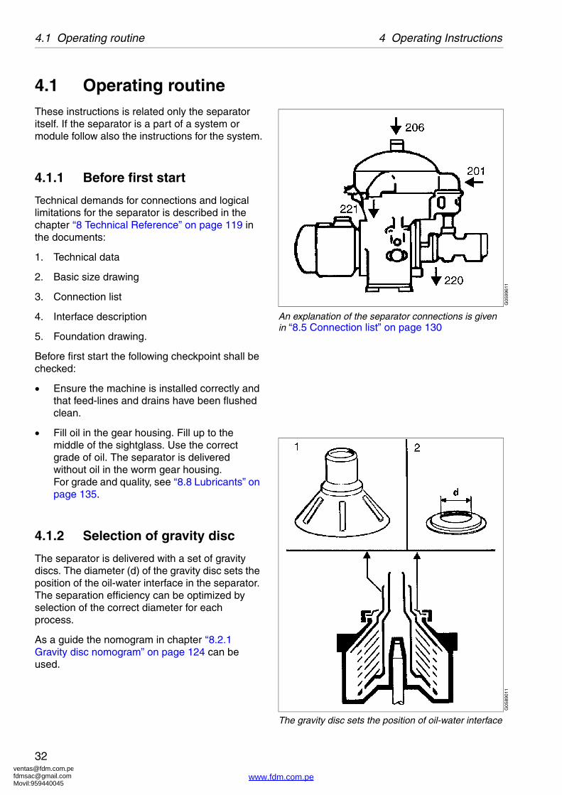
4.1 Operating routineThese instructions is related only the separator itself. If the separator is a part of a system or module follow also the instructions for the system.
4.1.1 Before first start
Technical demands for connections and logical limitations for the separator is described in the chapter ‘‘8 Technical Reference” on page 119 in the documents:
1. Technical data
2. Basic size drawing
3. Connection list
4. Interface description
5. Foundation drawing.
Before first start the following checkpoint shall be checked:
� Ensure the machine is installed correctly and that feed-lines and drains have been flushed clean.
� Fill oil in the gear housing. Fill up to the middle of the sightglass. Use the correct grade of oil. The separator is delivered without oil in the worm gear housing.�For grade and quality, see ‘‘8.8 Lubricants” on page 135.
4.1.2 Selection of gravity disc
The separator is delivered with a set of gravity discs. The diameter (d) of the gravity disc sets the position of the oil-water interface in the separator. The separation efficiency can be optimized by selection of the correct diameter for each process.
As a guide the nomogram in chapter ‘‘8.2.1 Gravity disc nomogram” on page 124 can be used.
G05
9961
1
An explanation of the separator connections is given in ‘‘8.5 Connection list” on page 130
G05
8901
1
The gravity disc sets the position of oil-water interface
www.fdm.com.pe
[email protected]@gmail.comMovil:959440045
33
4 Operating Instructions 4.1 Operating routine
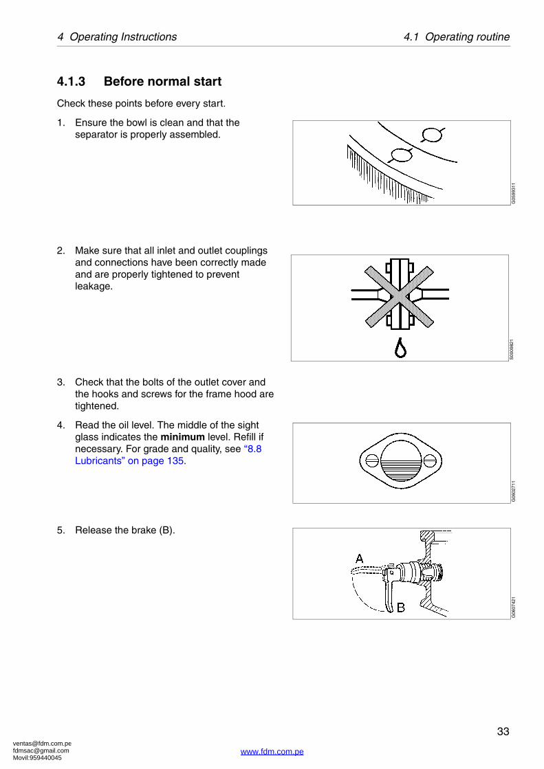
4.1.3 Before normal start
Check these points before every start.
1. Ensure the bowl is clean and that the separator is properly assembled.
2. Make sure that all inlet and outlet couplings and connections have been correctly made and are properly tightened to prevent leakage.
3. Check that the bolts of the outlet cover and the hooks and screws for the frame hood are tightened.
4. Read the oil level. The middle of the sight glass indicates the minimum level. Refill if necessary. For grade and quality, see ‘‘8.8 Lubricants” on page 135.
5. Release the brake (B).
G05
9931
1S
0009
821
G06
0271
1G
0607
421
www.fdm.com.pe

[email protected]@gmail.comMovil:959440045
4.1 Operating routine 4 Operating Instructions
34
6. Make sure the direction of rotation of the motor and bowl corresponds to the sign on the frame.
4.1.4 Starting and running-up procedure
1. After starting the separator, visually check to be sure that the motor and separator have started to rotate.
2. Check the direction of rotation. The revolution counter should run clockwise.
3. Be alert for unusual noises or conditions.
Smoke and odour may occur at the start when friction pads are new.
4. Note the normal occurrence of critical speed vibration periods.
G02
4622
1
Revolution counter
G06
0001
1Smell
S00
5561
1
Vibration
www.fdm.com.pe

[email protected]@gmail.comMovil:959440045
35
4 Operating Instructions 4.1 Operating routine
5. Motor current indicates when the separator has come to full speed.
During start the current reaches a peak and then slowly drops to a low and stable value. For normal length of the start-up period see ‘‘8.2 Technical data” on page 121.
WARNING
Disintegration hazards
When excessive vibration occurs, keep liquid feed on and stop separator.
The cause of the vibrations must be identified and corrected before the separator is restarted.
Excessive vibrations may be due to incorrect assembly or poor cleaning of the bowl.
S00
0962
1
Current increases when the coupling engages...
S00
0963
1
.... to decrease to a stable value when full speed has been reached
www.fdm.com.pe

[email protected]@gmail.comMovil:959440045
4.1 Operating routine 4 Operating Instructions
36
4.1.5 At full speed
1. For purification mode:
a. Supply water (206), approx. 1 liter (depending on Gravity disc) to form the water-seal. Continue until water flows out through the water outlet (221). The water should have the same temperature as the process liquid and be supplied quickly.
b. Close water feed.
c. Start the oil feed slowly to avoid breaking the water seal. Fill the bowl as quickly as possible.
2. For clarification mode:
a. Start the oil feed with full flow. Fill the bowl as quickly as possible.
3. For both purification and clarification mode:
Check the separator inlet and outlet pressures.
Adjust the oil outlet pressure to 1,5-2 bar. �For permissible pressures, see section ‘‘8.2 Technical data” on page 121.
4. Adjust to desired throughput.
G0877511
Using water adding device, see ‘‘8.9.3 Water adding device (option)” on page 150
www.fdm.com.pe

[email protected]@gmail.comMovil:959440045
37
4 Operating Instructions 4.1 Operating routine
4.1.6 During operation
Do regular checks on:
� oil inlet temperature (if applicable)
� water collecting tank level
� sound/vibration of the separator
� back pressure
� motor current.
4.1.7 Stopping procedure
1. Feed sealing water.
2. Turn off the oil feed.
3. Stop the separator.
4. Pull the brake. (A)
Wait until the separator has come to a complete standstill (2-5 minutes). Release the brake when the separator is at standstill. (B)
5. Manual cleaning should be carried out before next start up. See ‘‘4.2.1 Removal of separated sludge” on page 39.
WARNING
Entrapment hazards
Make sure that rotating parts have come to a complete standstill before starting any dismantling work.
The revolution counter and the motor fan indicate if the separator is rotating or not.
G06
0742
1S
0051
111
www.fdm.com.pe

[email protected]@gmail.comMovil:959440045
4.1 Operating routine 4 Operating Instructions
38
4.1.8 Emergency stop
The emergency stop is always installed according to local safety regulations. It is often a button placed on the wall near the separator or on the control equipment.
The following should happen automatically:
� The bowl is kept filled with liquid until standstill.
� The separator motor is switched off.
Evacuate the room. The separator may be hazardous when passing resonance frequencies during the run-down.
After an emergency stop the cause of the fault must be identified.
If all parts have been checked and the cause remains unclear contact your Alfa Laval representative for advice.
S00
0991
1
Emergency stop
www.fdm.com.pe

[email protected]@gmail.comMovil:959440045
39
4 Operating Instructions 4.2 Cleaning the bowl
4.2 Cleaning the bowlThe separated sludge is accumulating on the inside surface of the separator bowl. How often the separator needs to be cleaned, depends on the amount of sediment entering the separator. High solids content or high throughput has the consequence that the cleaning need to be done more often.
Guidelines for emptying intervals:
Marine diesel oil - 1 week
Lubricating oil - 1 day
Intervals for a specific case must be based on experience.
4.2.1 Removal of separated sludge
Remove the sludge collected on the inside of the bowl as follows:
1. Stop the separator.
2. Raise the collecting cover open. For instructions, see chapter ‘‘6 Dismantling/Assembly” on page 81.
WARNING
Entrapment hazards
Make sure that rotating parts have come to a complete standstill before starting any dismantling work.
The revolution counter and the motor fan indicate if the separator is rotating or not.
G06
0121
1
Sludge accumulation
S00
5111
1
www.fdm.com.pe

[email protected]@gmail.comMovil:959440045
4.2 Cleaning the bowl 4 Operating Instructions
40
3. Lock the bowl from rotating with the two lock screws.
4. Open the separator bowl.
5. Clean the bowl hood.
6. Clean the channels on the top disc upper side.
7. Remove sediment from the bowl body, clean and lubricate lock ring.
G05
9531
1G
0601
011
G06
0081
1G
0600
911
www.fdm.com.pe

[email protected]@gmail.comMovil:959440045
41
4 Operating Instructions 4.2 Cleaning the bowl
4.2.2 Sediment paper
To facilitate the cleaning of separators, a liner of plastic paper can be inserted in the bowl. Cut the paper into shape, moisten its plastic-coated side and press it against the inside of the bowl body. When cleaning remove the paper with the sediment cake.
4.2.3 Disc stack
When the sediment is not sticky, the disc stack can be cleaned by “hurling”.
1. Clean the other bowl parts.
2. Assemble the bowl.
3. Close and lock the collecting cover.
4. Run up to full speed without liquid feed.
5. After “hurling” either continue separation or stop and open the bowl and remove the sediment.
If the sediment adheres firmly, dissolve it by submerging the distributor and the disc stack in a suitable detergent.
If “hurling” has no effect, clean the discs one by one.
G06
0111
1
Sediment paper
G06
0121
1
Bowl cleaning by ‘hurling’
www.fdm.com.pe

[email protected]@gmail.comMovil:959440045
4.2 Cleaning the bowl 4 Operating Instructions
42
4.2.4 Assembling the bowl
Each bowl constitutes a balanced unit. Exchange of any major part necessitates rebalancing of the bowl. To prevent mixing of parts, e.g. in an installation comprising of several machines of the same type, the major bowl parts carry the machine manufacturing number or its last three digits.
Purifier bowl
The arrows indicate positions of guides on the bowl parts.
NOTEBe sure bowl parts are not interchanged.Out of balance vibration will reduce ball bearing life.
Lubrication needed
Balanced parts. �Exchange necessitates rebalancing of bowl.
G06
0031
1
Purifier bowl, exploded view
S00
0071
1S
0068
511
www.fdm.com.pe

[email protected]@gmail.comMovil:959440045
43
4 Operating Instructions 4.2 Cleaning the bowl
Clarifier bowl
The arrows indicate positions of guides on the bowl parts.
1. Clean spindle top and bowl body nave with a cloth.
Lubrication needed
Balanced parts. �Exchange necessitates rebalancing of bowl.
G06
0131
1
Clarifier bowl, exploded view
S00
0071
1S
0068
511
G06
0141
1
www.fdm.com.pe

[email protected]@gmail.comMovil:959440045
4.2 Cleaning the bowl 4 Operating Instructions
44
2. Bring bowl parts into positions defined by the guides.
3. Screw in both lock screws. Screw large lock ring anti-clockwise until bowl hood lies tightly against bowl body.
Slacken the two lock screws.
4. Lower and clamp the collecting cover and tighten both cap nuts to a maximum torque of 12 Nm.
NOTE
The two lock screws must be fully released to prevent risk for damage to bowl body.
G05
8891
1G
0601
511
G06
0021
1
Max. torque = 12 Nm.
www.fdm.com.pe
[email protected]@gmail.comMovil:959440045
45
5 Service Instructions
Contents
5.1 Periodic Maintenance 46
5.1.1 Introduction 46
5.1.2 Maintenance intervals 46
5.1.3 Maintenance procedure 47
5.1.4 Service kits 48
5.2 Maintenance Logs 48
5.2.1 Daily checks 49
5.2.2 Oil change 50
5.2.3 MS-Major Service 51
5.3 MS - Check points 54
5.3.1 Corrosion 54
5.3.2 Erosion 56
5.3.3 Cracks 57
5.3.4 Disc stack pressure 58
5.3.5 Lock ring; wear and damage 58
5.3.6 Radial wobble of bowl spindle 60
5.3.7 Bowl spindle cone and�bowl body nave 61
5.3.8 Coupling disc of motor 62
5.3.9 Friction pads 63
5.3.10 Brake plug 63
5.3.11 Top bearing springs 64
5.3.12 Ball bearing housing 64
5.3.13 Worm wheel and worm;�wear of teeth 65
5.3.14 Tooth appearance examples 66
5.3.15 Cover interlocking�switch, (Option) 67
5.4 Cleaning 68
5.4.1 External cleaning 68
5.4.2 Cleaning agents 69
5.4.3 Cleaning of bowl discs 71
5.5 When changing oil 72
5.5.1 Oil change procedure 72
5.6 Common maintenance�directions 74
5.6.1 Vibration 74
5.6.2 Ball and roller bearings 75
5.6.3 Friction coupling 77
5.6.4 Shutdowns 78
5.7 Lifting instructions 79
www.fdm.com.pe

[email protected]@gmail.comMovil:959440045
5.1 Periodic Maintenance 5 Service Instructions
46
5.1 Periodic Maintenance
5.1.1 Introduction
Periodic (preventive) maintenance reduces the risk of unexpected stoppages and breakdowns. Maintenance schedules are shown on the following pages in order to facilitate periodic maintenance.
5.1.2 Maintenance intervals
The following directions for periodic maintenance give a brief description of which components to be cleaned, checked and renewed at different maintenance intervals.
The maintenance logs for each maintenance interval later in this chapter give detailed enumeration of the check points that must be done.
Daily checks consist of minor check points to carry out for detecting abnormal operating conditions.
After a standstill for more than six months the spindle bearings should be prelubricated before restart. See also ‘‘5.6.4 Shutdowns” on page 78.
Oil change
The oil change interval is every 1500 hours or at least once every year if the total number of operating hours is less than 1500 hours.
When using a group D oil, time of operation between oil changes can be extended from the normal 1500 hours to 2000 hours.
G05
9391
1
Periodic maintenance prevent stoppages
G05
9051
1
Maintenance log
www.fdm.com.pe

[email protected]@gmail.comMovil:959440045
47
5 Service Instructions 5.1 Periodic Maintenance
MS - Major Service
Major Service consists of an overhaul of the complete separator every 12 months or 8000 operating hours. Seals and bearings in the bottom part are renewed.
5.1.3 Maintenance procedure
At each Major Service, take a copy of the Service Log and use it for notations during the service.
A Major Service should be carried out in the following manner:
1. Dismantle the parts as mentioned in the Service Log and described in ‘‘6.2 Dismantling” on page 83.
Place the separator parts on clean, soft surfaces such as pallets.
2. Inspect and clean the dismantled separator parts according to the Service Log.
3. Fit all the parts delivered in the Service kit while assembling the separator as described in ‘‘6.3 Assembly” on page 93. The assembly instructions have references to check points which should be carried out during the assembly.
2nd year
Oil change
Major Service = MS
4th year
Service schedule
Installation 1st year
MS MS MS MS
3rd year
www.fdm.com.pe

[email protected]@gmail.comMovil:959440045
5.2 Maintenance Logs 5 Service Instructions
48
5.1.4 Service kits
Service kits are available for Major Service (MS).
For other services the spare parts have to be ordered separately.
The contents of the service kits are described in the Spare Parts Catalogue.
5.2 Maintenance LogsKeep a log of inspection and maintenance performed. Parts repeatedly replaced should be given special consideration. The cause of repeated failures should be determined and corrected. Discuss your problems with an Alfa Laval representative and, when necessary, request a visit by an Alfa Laval Service engineer.
Rate of corrosion and erosion and notification of cracks should also be a part of this log. Note the extent of damage and date the log entries so that the rate of deterioration can be observed.
NOTE
Always use Alfa Laval genuine parts as otherwise the warranty will become invalid.
Alfa Laval takes no responsibility for the safe operation of the equipment if non-genuine spare parts are used.
C00
7810
1
Major service kit
www.fdm.com.pe

[email protected]@gmail.comMovil:959440045
49
5 Service Instructions 5.2 Maintenance Logs
5.2.1 Daily checks
The following steps should be carried out daily.
Main component and activity Part Page Notes
Inlet and outlet
Check for leakage Collecting cover and connecting housing
-
Separator bowl
Check for vibration and noise 74
Worm wheel shaft and gear casing
Check for vibration and noise
Check Oil level in gear housing 50
Electrical motor
Check for heat, vibration and noise 1)
1) See manufacturer’s instruction
www.fdm.com.pe

[email protected]@gmail.comMovil:959440045
5.2 Maintenance Logs 5 Service Instructions
50
5.2.2 Oil change
The oil change and check of worm gear should be carried out every 1500 * hours of operation.
* When using a group D oil, time of operation between oil changes can be extended from the normal 1500 hours to 2000 hours.
When the separator is running for short periods, the lubricating oil must be changed every 12 months even if the total number of operating hours is less than 1500 hours (2000 h).
In a new installation, or after replacement of gear, change the oil after 200 operating hours.
See chapter ‘‘8 Technical Reference” on page 119 for further information.
Main component and activity Part Page Notes
Worm wheel shaft and gear housing
Check Worm wheel and worm 65
Renew Oil * in gear housing 50
www.fdm.com.pe

[email protected]@gmail.comMovil:959440045
51
5 Service Instructions 5.2 Maintenance Logs
5.2.3 MS-Major Service
Name of plant: Local identification:
Separator: MAB 103B-24 Manufacture No./Year:
Total running hours: Product No: 881145-09-01/7
Date: Signature:
Main component and activity Part Page Notes
Inlet and outlet
Clean and inspect Threads of inlet pipe(s)-
Connecting housing -
Separator bowl
Clean and check Lock ring 58
Bowl hood 39
Top disc -
Gravity disc -
Bowl discs -
Distributor -
Bowl body -
Corrosion 54
Erosion 56
Cracks 57
Disc stack pressure 58
Renew O-rings and sealings -
www.fdm.com.pe

[email protected]@gmail.comMovil:959440045
5.2 Maintenance Logs 5 Service Instructions
52
Worm wheel shaft and gear housing
Check Worm wheel and worm 65
Radial wobble of worm wheel shaft
-
Axial play of coupling disc 62
Renew Oil in gear housing 50
Vertical driving device
Clean and check Bowl spindle 61
Wear of driver and of groove in worm
65
Buffers 60
Ball bearing housing indentations
64
Radial wobble of bowl spindle 60
Renew Ball bearings and top bearing springs
61
Brake
Clean and check Spring and brake shoe -
Renew Brake plug 63
Pump
Clean and check Bushings, wearing seals, shear pin coupling and impeller shaft.
102
Renew Lipseal ring 102
Name of plant: Local identification:
Separator: MAB 103B-24 Manufacture No./Year:
Total running hours: Product No: 881145-09-01/7
Date: Signature:
Main component and activity Part Page Notes
www.fdm.com.pe

[email protected]@gmail.comMovil:959440045
53
5 Service Instructions 5.2 Maintenance Logs
Friction coupling
Clean and check Friction coupling 77
Renew Friction pads
Renew Lipseal ring
Frame feet
Renew Rubber cushions 108
Electrical motor
Clean and check Position of coupling disc 62
Lubrication (if nipples are fitted) - -
Signs and labels on separator
Check attachment and readability, replace if needed
Safety label on collecting cover
162
Monitoring equipment (option)
Function check Cover interlocking switch 67
NOTE
Renew all parts included in the Major Service kit (MS).
Name of plant: Local identification:
Separator: MAB 103B-24 Manufacture No./Year:
Total running hours: Product No: 881145-09-01/7
Date: Signature:
Main component and activity Part Page Notes
www.fdm.com.pe

[email protected]@gmail.comMovil:959440045
5.3 MS - Check points 5 Service Instructions
54
5.3 MS - Check points
5.3.1 Corrosion
Evidence of corrosion attacks should be looked for and rectified each time the separator is dismantled. Main bowl parts such as the bowl body, bowl hood and lock ring must be inspected with particular care for corrosion damage.
Always contact your Alfa Laval representative if you suspect that the largest depth of the corrosion damage exceeds 1,0 mm or if cracks have been found. Do not continue to use the separator until it has been inspected and given clearance for operation by Alfa Laval.
Cracks or damage forming a line should be considered as being particularly hazardous.
Non-stainless steel and cast iron parts
Corrosion (rusting) can occur on unprotected surfaces of non-stainless steel and cast iron. Frame parts can corrode when exposed to an aggressive environment.
WARNING
Disintegration hazard
Inspect regularly for corrosion damage. Inspect frequently if the process liquid is corrosive.
G05
8981
1
Main bowl parts
www.fdm.com.pe

[email protected]@gmail.comMovil:959440045
55
5 Service Instructions 5.3 MS - Check points
Stainless steel
Stainless steel parts corrode when in contact with either chlorides or acidic solutions. Acidic solutions causes a general corrosion. The chloride corrosion is characterised by local damage such as pitting, grooves or cracks. The risk of chloride corrosion is higher if the surface is:
� Exposed to a stationary solution.
� In a crevice.
� Covered by deposits.
� Exposed to a solution that has a low pH 75
� value.
Corrosion damage caused by chlorides on stainless steel begins as small dark spots that can be difficult to detect.
� Inspect closely for all types of damage by corrosion and record these observations carefully.
� Polish dark-coloured spots and other corrosion marks with a fine grain emery cloth. This may prevent further damage.
Other metal parts
Separator parts made of materials other than steel, such as brass or other copper alloys, can also be damaged by corrosion when exposed to an aggressive environment. Possible corrosion damage can be in the form of pits and/or cracks.
WARNING
Disintegration hazard
Pits and spots forming a line may indicate cracks beneath the surface.
All forms of cracks are a potential danger and are totally unacceptable.
Replace the part if corrosion can be suspected of affecting its strength or function.
S00
2061
1
Corrosion forming a line
S00
2051
1
Polish corrosion spots
www.fdm.com.pe

[email protected]@gmail.comMovil:959440045
5.3 MS - Check points 5 Service Instructions
56
5.3.2 Erosion
Erosion can occur when particles suspended in the process liquid slide along or strike against a surface. Erosion can become intensified locally by flows of higher velocity.
Always contact your Alfa Laval representative if the largest depth of any erosion damage exceeds 1,0 mm. Valuable information as to the nature of the damage can be recorded using photographs, plaster impressions or hammered-in lead.
Erosion is characterised by:
� Burnished traces in the material.
� Dents and pits having a granular and shiny surface.
Surfaces particularly subjected to erosion are:
1. The underside of the distributor in the vicinity of the distribution holes and wings.
2. The internal surface of the bowl body that faces the conical part of the distributor.
Look carefully for any signs of erosion damage. Erosion damage can deepen rapidly and consequently weaken parts by reducing the thickness of the metal.
WARNING
Disintegration hazard
Inspect regularly for erosion damage. Inspect frequently if the process liquid is erosive.
WARNING
Disintegration hazard
Erosion damage can weaken parts by reducing the thickness of the metal.Replace the part if erosion can be suspected of affecting its strength or function.
G02
0522
1
Maximum depth of damage
G05
8991
1
Erosion check points
www.fdm.com.pe

[email protected]@gmail.comMovil:959440045
57
5 Service Instructions 5.3 MS - Check points
5.3.3 Cracks
Cracks can initiate on the machine after a period of operation and propagate with time.
� Cracks often initiate in an area exposed to high cyclic material stresses. These are called fatigue cracks.
� Cracks can also initiate due to corrosion in an aggressive environment.
� Although very unlikely, cracks may also occur due to the low temperature embrittlement of certain materials.
The combination of an aggressive environment and cyclic stresses will speed-up the formation of cracks. Keeping the machine and its parts clean and free from deposits will help to prevent corrosion attacks.
It is particularly important to inspect for cracks in rotating parts.
Always contact your Alfa Laval representative if you suspect that the largest depth of the damage exceeds 1,0 mm. Do not continue to use the separator until it has been inspected and cleared for operation by Alfa Laval.
WARNING
Disintegration hazard
All forms of cracks are potentially dangerous as they reduce the strength and functional ability of components.
Always replace a part if cracks are present.
www.fdm.com.pe

[email protected]@gmail.comMovil:959440045
5.3 MS - Check points 5 Service Instructions
58
5.3.4 Disc stack pressure
The lock ring (1) should press the bowl hood (2) firmly against the bowl body (3). The hood in turn should exert a pressure on the disc stack (4), clamping it in place.
Compress the disc stack by tightening the lock ring, see chapter ‘‘6.3.3 Bowl” on page 98.
Correct pressure is obtained when it is possible to tighten the lock ring so far by hand that the��-mark on the lock ring is positioned 60° - 90° before the mark on the bowl hood.
To achieve this, add an appropriate number of discs to the top of the disc stack beneath the top disc.
Then advance the lock ring by giving the spanner handle some blows till the �-marks are passed and the bowl is fully assembled.
5.3.5 Lock ring; wear and damage
Excessive wear or impact marks on threads, guide and contact surfaces of the lock ring, bowl hood and bowl body may cause hazardous galling.
Check the thread condition by tightening the lock ring after removing the disc stack and bowl hood O-ring from the bowl.
NOTE
Insufficient pressure in disc stack can cause out of balance vibration and reduced lifetime of ball bearings.
G05
9272
1
Disc stack pressure check
G05
9271
1
Add discs to achieve disc stack pressure
G05
9241
1
Wear of lock ring
www.fdm.com.pe

[email protected]@gmail.comMovil:959440045
59
5 Service Instructions 5.3 MS - Check points
In a new bowl the alignment marks on the lock ring and the bowl hood are exactly opposite each other.
If thread wear is observed, mark the bowl hood at the new position of the alignment mark on the lock ring by punching in a new alignment mark.
Contact Your Alfa Laval representative
� If the original mark on the lock ring passes the corresponding mark on the bowl hood by more than 25° (or 25 mm).
� If the alignment marks become illegible. The thread wear need to be inspected and the new position of alignment marks determined.
Damage
The position of the threads, contact and guide surfaces are indicated by arrows in the illustration.
Clean the threads, contact and guide surfaces with a suitable degreasing agent.
Check for burrs and protrusions caused by impact. Watch your fingers for sharp edges.
If damage is established, rectify using a whetstone or fine emery cloth (recommended grain size 240).
If the damage is considerable, use a fine single-cut file, followed by a whetstone.
WARNING
Disintegration hazards
Wear on large lock ring thread must not exceed safety limit. The �-mark on lock ring must not pass opposite �-mark by more than the specified distance.
G05
9261
1
Maximum wear A=25 ° (or 25 mm)
www.fdm.com.pe
[email protected]@gmail.comMovil:959440045
5.3 MS - Check points 5 Service Instructions
60
5.3.6 Radial wobble of bowl spindle
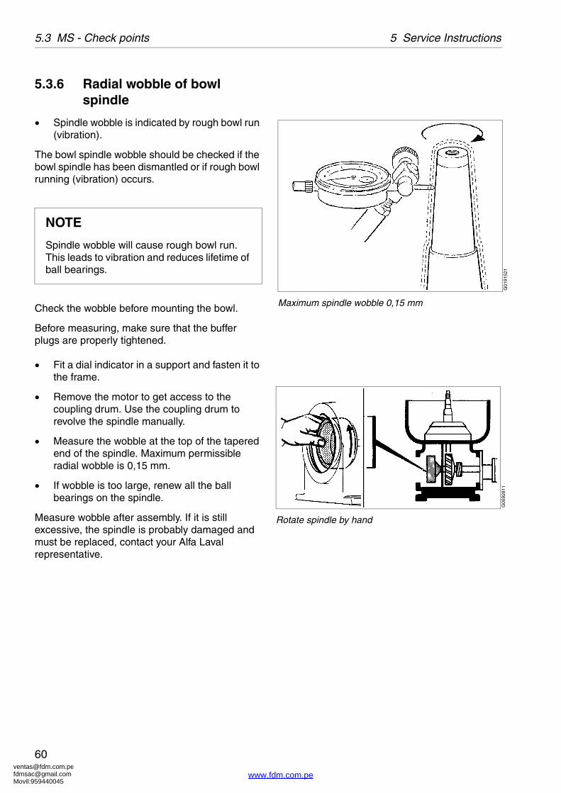
� Spindle wobble is indicated by rough bowl run (vibration).
The bowl spindle wobble should be checked if the bowl spindle has been dismantled or if rough bowl running (vibration) occurs.
Check the wobble before mounting the bowl.
Before measuring, make sure that the buffer plugs are properly tightened.
� Fit a dial indicator in a support and fasten it to the frame.
� Remove the motor to get access to the coupling drum. Use the coupling drum to revolve the spindle manually.
� Measure the wobble at the top of the tapered end of the spindle. Maximum permissible radial wobble is 0,15 mm.
� If wobble is too large, renew all the ball bearings on the spindle.
Measure wobble after assembly. If it is still excessive, the spindle is probably damaged and must be replaced, contact your Alfa Laval representative.
NOTE
Spindle wobble will cause rough bowl run. This leads to vibration and reduces lifetime of ball bearings.
G01
9152
1
Maximum spindle wobble 0,15 mm
G05
9281
1
Rotate spindle by hand
www.fdm.com.pe

[email protected]@gmail.comMovil:959440045
61
5 Service Instructions 5.3 MS - Check points
5.3.7 Bowl spindle cone and bowl body nave
Impact marks on the spindle cone or in the bowl body nave may cause poor fit and out-of-balance vibrations.
The bowl spindle and the nave should also be checked if the bowl spindle has been dismantled or if the bowl runs roughly.
Corrosion may cause the bowl to stick firmly to the spindle cone and cause difficulties during the next dismantling.
� Remove any impact marks with a scraper and/or whetstone.
Rust can be removed by using a fine-grain emery cloth (e.g. No 320).
Finish with polishing paper (e.g. No 600).
Wipe off the spindle top and nave bore in the bowl body. Lubricate the tapered end of the spindle and wipe it of with a clean cloth before assembling.
NOTEAlways use a scraper with great care. The conicity must not be marred.
G05
9091
1
Put a little oil on the bowl spindle and wipe it of with a clean cloth to prevent corrosion
www.fdm.com.pe

[email protected]@gmail.comMovil:959440045
5.3 MS - Check points 5 Service Instructions
62
5.3.8 Coupling disc of motor
The position of the coupling disc on the motor shaft is establishing the location of the friction pads inside the coupling.
If the coupling disc is loosened without first marking its position on the motor shaft, the correct position must be determined again.
1. Measure the distance on the frame.
2. Measure the distance on the motor.
3. The coupling disc is in correct position when frame distance (1) is 16-17 mm larger than motor distance (2). See fig.
G05
9331
1
Frame distance
G05
9341
1
Motor distance
G05
9351
1
Position of coupling disc
www.fdm.com.pe

[email protected]@gmail.comMovil:959440045
63
5 Service Instructions 5.3 MS - Check points
5.3.9 Friction pads
Worn or oily pads will cause a long running-up period. Replace all the pads even when only one of them is worn.
If the pads are oily:
� Clean the pads as well as the inside of the coupling drum with a suitable degreasing agent.
� Roughen up the friction surfaces of the pads with a coarse file.
5.3.10 Brake plug
A worn brake plug will cause a long stopping period.
Replace the plug when the friction material is worn. If the thickness A of the friction material is less than 0,5 mm the brake plug need to be replaced.
G05
9321
1
Friction coupling
G05
9311
1
Maximum wear of brake plug when A=0,5 mm
www.fdm.com.pe

[email protected]@gmail.comMovil:959440045
5.3 MS - Check points 5 Service Instructions
64
5.3.11 Top bearing springs
Weakened or broken buffer springs may give rise to machine vibration (rough bowl running).
The condition (stiffness) of a spring can hardly be determined without using special testing equipment. So, an estimation of the spring condition must be based on the knowledge of the machine run before the overhaul. It is recommended, however, to replace all the springs at the annual overhaul.
In case of a sudden spring fracture, all springs should be replaced even when only one spring has broken.
5.3.12 Ball bearing housing
� Defective contact surfaces for the buffers on the ball bearing housing may give rise to machine vibration (rough bowl running).
Examine the contact surface for the buffers (1) on the ball bearing housing (3). In case of defects (indentations deeper than 0,1 mm) replace the housing as well as buffers and springs.
G05
9301
1
1. Radial buffer2. Buffer spring3. Ball bearing housing
www.fdm.com.pe

[email protected]@gmail.comMovil:959440045
65
5 Service Instructions 5.3 MS - Check points
5.3.13 Worm wheel and worm; wear of teeth
Check the teeth of worm wheel and worm for wear.
See ‘‘5.3.14 Tooth appearance examples” on page 66.
Examine the contact surfaces and compare the tooth profiles. The gear may operate satisfactorily even when worn to some degree.
When using mineral-type oil in the worm gear housing, the presence of black deposits on the spindle parts is an indication that the oil base has deteriorated seriously or that some of the oil additives have precipitated. If pits are found on the worm gear, the cause could be that the additives are not suitable for this purpose.
In all these cases it is imperative to change to a high-temperature oil. See chapter ‘‘8.8 Lubricants” on page 135.
NOTE
Replace both worm wheel and worm at the same time, even if only one of them is worn.
NOTE
Presence of metal chips in the oil bath is an indication that the gear is wearing abnormally.
G05
9291
1
1. Worm wheel2. Worm (part of bowl spindle)
G02
0541
1
Inspect the gear for deposits and pits
www.fdm.com.pe

[email protected]@gmail.comMovil:959440045
5.3 MS - Check points 5 Service Instructions
66
5.3.14 Tooth appearance examples
Satisfactory teeth:
Uniform wear of contact surfaces. Surfaces are smooth.
Good contact surfaces will form on the teeth when the gear is subjected to only moderate load during its running-in period.
Worn teeth:
Permissible wear is as a rule 1/3 of the thickness of the upper part of a tooth, provided that
� the wear is uniform over the whole of the flank of a tooth
� and all teeth are worn in the same way.
Spalling:
Small bits of the teeth have broken off, so-called spalling. This is generally due to excessive load or improper lubrication. Damage of this type need not necessitate immediate replacement, but careful checking at short intervals is imperative.
Pitting:
Small cavities in the teeth, so-called pitting, can occur through excessive load or improper lubrication. Damage of this type need not necessitate immediate replacement, but careful check at short intervals is imperative.
G05
3871
1
Satisfactory teeth
G05
3881
1
Worn teeth
G05
3891
1
Spalling
G05
3901
1
Pitting
www.fdm.com.pe

[email protected]@gmail.comMovil:959440045
67
5 Service Instructions 5.3 MS - Check points
5.3.15 Cover interlocking switch, (Option)
Make sure that the switch is connection perfectly and mounted in the correct manner in order to obtain the appropriate safety that is required.
23
1
A
G05
4816
1
www.fdm.com.pe
[email protected]@gmail.comMovil:959440045
5.4 Cleaning 5 Service Instructions
68
5.4 Cleaning
5.4.1 External cleaning
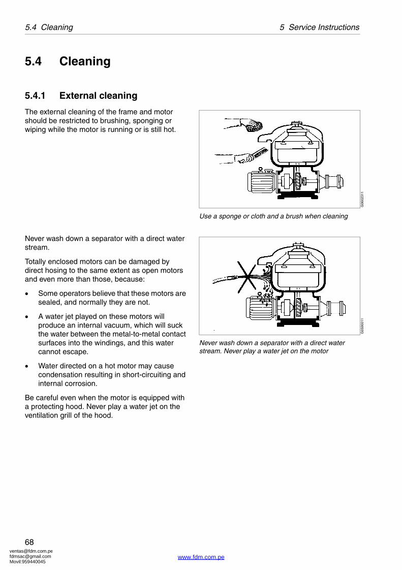
The external cleaning of the frame and motor should be restricted to brushing, sponging or wiping while the motor is running or is still hot.
Never wash down a separator with a direct water stream.
Totally enclosed motors can be damaged by direct hosing to the same extent as open motors and even more than those, because:
� Some operators believe that these motors are sealed, and normally they are not.
� A water jet played on these motors will produce an internal vacuum, which will suck the water between the metal-to-metal contact surfaces into the windings, and this water cannot escape.
� Water directed on a hot motor may cause condensation resulting in short-circuiting and internal corrosion.
Be careful even when the motor is equipped with a protecting hood. Never play a water jet on the ventilation grill of the hood.
G06
0231
1
Use a sponge or cloth and a brush when cleaning
G05
9001
1
Never wash down a separator with a direct water stream. Never play a water jet on the motor
www.fdm.com.pe

[email protected]@gmail.comMovil:959440045
69
5 Service Instructions 5.4 Cleaning
5.4.2 Cleaning agents
When using chemical cleaning agents, make sure you follow the general rules and supplier’s recommendations regarding ventilation, protection of personnel, etc.
For separator bowl, inlet and outlet
A chemical cleaning agent must dissolve the deposits quickly without attacking the material of the separator parts.
� For cleaning of lube oil separators the most important function of the cleaning agent is to be a good solvent for the gypsum in the sludge. It should also act as a dispersant and emulsifier for oil. It is recommended to use Alfa-Laval cleaning liquid for lube oil separators which has the above mentioned qualities. Note that carbon steel parts can be damaged by the cleaning agent if submerged for a long time.
� Fuel oil sludge mainly consists of complex organic substances such as asphaltenes. The most important property of a cleaning liquid for the removal of fuel oil sludge is the ability to dissolve these asphaltenes.
Alfa Laval cleaning liquid of fuel oil separators has been developed for this purpose. The liquid is water soluble, non-flammable and does not cause corrosion of brass and steel. It is also gentle to rubber and nylon gaskets in the separator bowl.
Before use, dilute the liquid with water to a concentration of 3-5%. Recommended cleaning temperature is 50-70 °C.
CAUTION
Skin irritation hazard
Read the instructions on the label of the plastic container before using the cleaning liquid.
Always wear safety goggles, gloves and protective clothing as the liquid is alkaline and dangerous to skin and eyes.
S00
0851
1
Alfa Laval cleaning liquid for lube oil separators is available in 25-litre plastic containers.Part No. 1762852-01.
Alfa Laval cleaning liquid for fuel oil separators is available in 5-litre plastic containers.Part No. 1763500-01.
www.fdm.com.pe

[email protected]@gmail.comMovil:959440045
5.4 Cleaning 5 Service Instructions
70
For parts of the driving devices
Use white spirit, cleaning-grade kerosene or diesel oil.
Oiling (protect surfaces against corrosion)
Protect cleaned carbon steel parts against corrosion by oiling. Separator parts that are not assembled after cleaning must be wiped and coated with a thin layer of clean oil and protected from dust and dirt.
G05
9091
1
Oil parts to protect from corrosion
www.fdm.com.pe

[email protected]@gmail.comMovil:959440045
71
5 Service Instructions 5.4 Cleaning
5.4.3 Cleaning of bowl discs
Bowl discs
Handle the bowl discs carefully so as to avoid damage to the surfaces during cleaning.
1. Remove the bowl discs from the distributor and lay them down, one by one, in the cleaning agent.
2. Let the discs remain in the cleaning agent until the deposits have been dissolved. This will normally take between two and four hours.
3. Finally clean the discs with a soft brush.
NOTE
Mechanical cleaning is likely to scratch the disc surfaces causing deposits to form quicker and adhere more firmly.
A gentle chemical cleaning is therefore preferable to mechanical cleaning.
CAUTION
Cut hazard
The discs have sharp edges.G
0065
831
Put the discs one by one into the cleaning agent
G00
6584
1
Clean the discs with a soft brush
www.fdm.com.pe

[email protected]@gmail.comMovil:959440045
5.5 When changing oil 5 Service Instructions
72
5.5 When changing oil
Check at each oil change
Check the teeth of both the worm wheel and worm for wear.
5.5.1 Oil change procedure
1. Place a collecting tray under the drain hole, remove the drain plug and drain off the oil.
NOTE
Before adding or renewing lubricating oil in the worm gear housing, the information concerning different oil groups, handling of oils, oil change intervals etc. given in chapter ‘‘8 Technical Reference” on page 119 must be well known.
CAUTION
Burn hazards
Lubricating oil and various machine surfaces can be sufficiently hot to cause burns.
G06
0251
1
1. Oil filling plug2. Sight glass3. Oil drain plug
G06
0261
1
Drain oil
www.fdm.com.pe

[email protected]@gmail.comMovil:959440045
73
5 Service Instructions 5.5 When changing oil
2. Fill new oil in the worm gear housing. The oil level should be slightly above middle of the sight glass. See chapter ‘‘8.2 Technical data” on page 121.
G06
0271
1
Oil level in sight glass
www.fdm.com.pe

[email protected]@gmail.comMovil:959440045
5.6 Common maintenance directions 5 Service Instructions
74
5.6 Common maintenance directions
5.6.1 Vibration
A separator normally vibrates and make noises, when it passes its critical speeds, during the start and stop periods.
It is recommended to get familiar with the normal behaviour of the machine.
Severe vibrations or noise indicates that something is incorrect. Stop the machine and identify the cause.
Use vibration analysis instrument to periodically check and record the level of vibration.
The level of vibration should not exceed maximum for separator in use (7,1 mm/s).
WARNING
Disintegration hazards
When excessive vibration occurs, keep liquid feed on and stop separator.
The cause of the vibration must be identified and corrected before the separator is restarted. Excessive vibration can be due to incorrect assembly or poor cleaning of the bowl.
S00
5561
1
Vibration
www.fdm.com.pe
[email protected]@gmail.comMovil:959440045
75
5 Service Instructions 5.6 Common maintenance directions
5.6.2 Ball and roller bearings
Use the greatest cleanliness when handling rolling bearings. Avoid unnecessary dismounting of bearings. Do not re-fit a used bearing, always replaced it with a new one.
Important: Specially designed bearings are used for the bowl spindle.
The bearings used for the bowl spindle are specifically designed to withstand the speed, vibration, temperature and load characteristics of high-speed separators.
Do not use other bearings than those stated in the Spare Parts Catalogue.
A bearing that in appearance looks equivalent to the correct bearing may be considerably different from the latter in various respects: inside clearances, design and tolerances of the cage and ball (roller) races as well as material and heat treatment. Any deviation from the correct bearing may cause a serious breakdown.
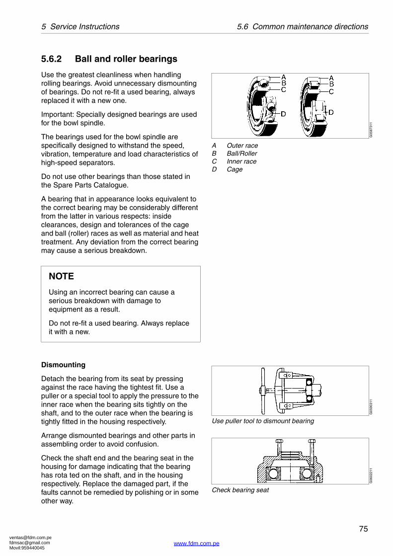
Dismounting
Detach the bearing from its seat by pressing against the race having the tightest fit. Use a puller or a special tool to apply the pressure to the inner race when the bearing sits tightly on the shaft, and to the outer race when the bearing is tightly fitted in the housing respectively.
Arrange dismounted bearings and other parts in assembling order to avoid confusion.
Check the shaft end and the bearing seat in the housing for damage indicating that the bearing has rota ted on the shaft, and in the housing respectively. Replace the damaged part, if the faults cannot be remedied by polishing or in some other way.
NOTE
Using an incorrect bearing can cause a serious breakdown with damage to equipment as a result.
Do not re-fit a used bearing. Always replace it with a new.
G05
8731
1
A Outer raceB Ball/RollerC Inner raceD Cage
G05
9031
1
Use puller tool to dismount bearing
G06
0221
1
Check bearing seat
www.fdm.com.pe

[email protected]@gmail.comMovil:959440045
5.6 Common maintenance directions 5 Service Instructions
76
Fitting
Leave new bearings in original wrapping until ready to fit. The anti-rust agent protecting a new bearing need not to be removed.
Fit a bearing on a shaft by pressure applied to the inner race and in a housing by pressure applied to the outer race. Use a suitable piece of pipe or a metal drift and a hammer. Never strike the bearing directly.
Bearings sitting with tight fit on a shaft should be heated in oil before assembly. The oil temperature should not exceed 125 °C. Never leave the bearing in the oil bath longer than required for thorough heating.
Angular contact ball bearings
Always fit single-row angular contact ball bearings with the stamped side of the inner race facing the axial load.
NOTE
Do not strike with a hammer directly on the bearing.
G05
9041
1
Use assembly tools
G06
0241
1
Use assembly tool
G05
8721
1
Angular contact bearing must be assembled correctly
www.fdm.com.pe

[email protected]@gmail.comMovil:959440045
77
5 Service Instructions 5.6 Common maintenance directions
5.6.3 Friction coupling
If the separator does not attain full speed within about two minutes, the friction elements or the coupling may be worn or greasy. The friction elements must then be replaced with new ones or carefully cleaned from grease.
Before the friction coupling is assembled, examine all parts thoroughly for wear and corrosion.
CAUTION
Inhalation hazard
When handling friction blocks/pads use a dust mask to make sure not to inhalate any dust.
Do not use compressed air for removal of any dust. Remove dust by vacuum or wet cloth.
See Safety instructions for environmental issues regarding correct disposal of used friction blocks/pads.
G05
9321
1
Friction coupling
www.fdm.com.pe

[email protected]@gmail.comMovil:959440045
5.6 Common maintenance directions 5 Service Instructions
78
5.6.4 Shutdowns
,If the separator is shut down for a period of time, the following must be carried out:
� Remove the bowl, according to instructions in chapter ‘‘6 Dismantling/Assembly” on page 81.
� Protect cleaned carbon steel parts against corrosion by oiling. Separator parts that are not assembled after cleaning must be wiped and protected against dust and dirt.
� The O-rings should be removed.
� If the separator has been shut down for more than 12 months, a Major Service (MS) should be carried out.
NOTE
The bowl must not be left on the spindle during standstill for more than one week.
VIbration in foundations can be transmitted to the bowl and produce one-sided loading of the bearings.
The resultant indentations in the ball bearing races can cause premature bearing failure.
G05
9022
1
Preparation for shutdown
www.fdm.com.pe

[email protected]@gmail.comMovil:959440045
79
5 Service Instructions 5.7 Lifting instructions
5.7 Lifting instructionsFor lifting parts and assemblies of parts use lifting slings, working load limit (WLL): 300 kg.
Lifting the separator
1. Remove the cap nut on the hinged bolt.
2. Remove the separator bowl.
3. Assemble the lifting eye on hinged bolts �(the screws must be tightened with spanner).
4. Attach endless slings or cables to the lifting eyes.
5. Lift and handle with care.
NOTERemove the separator bowl before lifting to prevent bearings to be damaged.
WARNING
Crush hazards
A dropped separator can cause accidents resulting in serious injury to persons and damage to equipment.
G05
9135
1
Do not lift the separator in any other way
www.fdm.com.pe

[email protected]@gmail.comMovil:959440045
5.7 Lifting instructions 5 Service Instructions
80
www.fdm.com.pe

[email protected]@gmail.comMovil:959440045
81
6 Dismantling/Assembly
Contents
6.1 General 82
6.1.1 References to check points 82
6.1.2 Tools 82
6.2 Dismantling 83
6.2.1 Bowl 83
6.2.2 Vertical driving device 87
6.2.3 Horizontal driving device 91
6.3 Assembly 93
6.3.1 Vertical driving device 93
6.3.2 Horizontal driving device 94
6.3.3 Bowl 98
6.4 Feed and discharge pumps 101
6.4.1 Exchange of shear�pin coupling 102
6.5 Oil filling 106
6.6 Brake 107
6.6.1 Checking of brake plug 107
6.7 Frame feet 108
6.7.1 Mounting of new frame feet 108
www.fdm.com.pe

[email protected]@gmail.comMovil:959440045
6.1 General 6 Dismantling/Assembly
82
6.1 GeneralThe parts must be handled carefully. Don’t place parts directly on the floor, but on a clean rubber mat, fibreboard or a suitable pallet.
6.1.1 References to check points
In the text you will find references to the check point instructions in Chapter 5. The references appear in the text as in the following example:
✔ Check point‘‘5.3.4 Disc stack pressure” on page 58.
In this example, look up check point ‘‘5.3.4 Disc stack pressure” on page 58 for further instructions.
6.1.2 Tools
Special tools from the tool kit shall be used for dismantling and assembly. The special tools are specified in the Spare Parts Catalogue.
NOTE
For lifting parts and assemblies of parts use lifting slings, working load limit (WLL): 300 kg
www.fdm.com.pe

[email protected]@gmail.comMovil:959440045
83
6 Dismantling/Assembly 6.2 Dismantling
6.2 DismantlingTo avoid accidental start, switch off and lock power supply.
6.2.1 Bowl
1. Be sure the bowl has stopped rotating.
2. Loosen the cap nuts and open the collecting cover.
WARNING
Entrapment hazards
Make sure that rotating parts have come to a complete standstill before starting any dismantling work.
The revolution counter and the motor fan indicates if separator parts are rotating or not.
S00
5101
1S
0051
111
G02
4622
1G
0600
211
www.fdm.com.pe

[email protected]@gmail.comMovil:959440045
6.2 Dismantling 6 Dismantling/Assembly
84
3. Tighten both lock screws.
The bowl parts can remain hot for a considerable time after the separator has come to a standstill.
4. Unscrew the small lock ring by using the special tool, “Spanner for small lock ring”.
Left hand thread!
5. Unscrew the large lock ring by using the special tool; “Spanner for lock ring” and a tin hammer.
Left hand thread!
G05
9501
1G
0595
111
G05
9521
1
www.fdm.com.pe

[email protected]@gmail.comMovil:959440045
85
6 Dismantling/Assembly 6.2 Dismantling
6. Lift off gravity disc/clarifier disc.
Lift out the top disc, disc stack and distributor.
7. Unscrew the cap nut (1).
Release the lock screws (2).
Lift out the bowl body using the hand tool (3).
8. Disconnect the piping connections.
NOTE
If the gravity disc has to be replaced owing to changed operating conditions, see ‘‘8.2.1 Gravity disc nomogram” on page 124.
CAUTION
Cut hazard
The discs have sharp edges.
G05
9531
1G
0595
411
1 Cap nut2 Lock screws3 Lift bowl body from spindle
G05
9551
1
www.fdm.com.pe
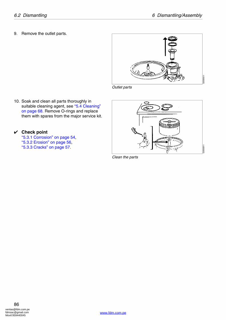
[email protected]@gmail.comMovil:959440045
6.2 Dismantling 6 Dismantling/Assembly
86
9. Remove the outlet parts.
10. Soak and clean all parts thoroughly in suitable cleaning agent, see ‘‘5.4 Cleaning” on page 68. Remove O-rings and replace them with spares from the major service kit.
✔ Check point‘‘5.3.1 Corrosion” on page 54,‘‘5.3.2 Erosion” on page 56,‘‘5.3.3 Cracks” on page 57.
G05
9561
1
Outlet parts
G05
9091
1
Clean the parts
www.fdm.com.pe

[email protected]@gmail.comMovil:959440045
87
6 Dismantling/Assembly 6.2 Dismantling
6.2.2 Vertical driving device
Remove the outlet housings, feed and discharge pumps and raise the collecting cover. Remove also the separator bowl.
Before dismantling, in the case of 8000 hours service, or if the separator vibrates while running:
✔ Check point‘‘5.3.6 Radial wobble of bowl spindle” on page 60.
1. Remove the pump assembly. Inspect the bushings and the wear of seals.
2. Loosen the screw for the revolution counter and pull out the revolution counter.
G05
9571
1G
0595
811
www.fdm.com.pe

[email protected]@gmail.comMovil:959440045
6.2 Dismantling 6 Dismantling/Assembly
88
3. Force out the conical pin, using a tin hammer as a holder-on for the worm wheel shaft.
4. Use the puller-tool to first pull off the bearing and then the worm wheel.
5. Loosen the top bearing holder.
G05
9831
1G
0596
011
G05
9611
1
www.fdm.com.pe

[email protected]@gmail.comMovil:959440045
89
6 Dismantling/Assembly 6.2 Dismantling
6. Fit the cap nut to the spindle top and lift the spindle.
7. Use the puller-tool to remove the bottom bearing from the spindle.
8. Loosen and inspect the buffer springs.
9. Pull off the upper ball breaking (together with sleeve).
NOTE
Always discard a used bearing.
G05
9621
1G
0596
311
G05
9641
1G
0596
511
www.fdm.com.pe

[email protected]@gmail.comMovil:959440045
6.2 Dismantling 6 Dismantling/Assembly
90
10. Every 3 years: clean the oil sump.
11. Clean all dismantled parts thoroughly in a degreasing agent and check for damage and corrosion.
✔ Check point‘‘5.3.1 Corrosion” on page 54.
Replace all parts supplied in the spare parts kit.
G05
9101
1
www.fdm.com.pe

[email protected]@gmail.comMovil:959440045
91
6 Dismantling/Assembly 6.2 Dismantling
6.2.3 Horizontal driving device
1. Remove the motor.
2. Renew the pads on the friction blocks.
When refitting the blocks make sure the arrow on each block points in the same direction of rotation. See the arrow on the frame.
Secure the blocks with washer and split pin.
If the friction elements are worn: fit new ones.
Replace all friction elements even if only one is worn.
If the friction elements are only greasy:�clean the friction elements and the inside of the coupling drum with a degreasing agent.
3. Loosen the three screws holding the sealing washer. Use a hexagon key.
CAUTION
Inhalation hazard
When handling friction blocks/pads use a dust mask to make sure not to inhalate any dust.
Do not use compressed air for removal of any dust. Remove dust by vacuum or wet cloth.
See Safety instructions for environmental issues regarding correct disposal of used friction blocks/pads.
G05
9661
1G
0593
211
G05
9671
1
www.fdm.com.pe

[email protected]@gmail.comMovil:959440045
6.2 Dismantling 6 Dismantling/Assembly
92
4. Remove the worm wheel shaft.
5. Use the puller tool to pull off the sealing washer. Protect end of worm wheel shaft with a washer.
6. To replace coupling drum or worm wheel shaft force out the spring pin and gently knock out the shaft.
7. Knock out the horizontal spindle.
G05
9681
1G
0596
911
G05
9701
1G
0597
111
www.fdm.com.pe

[email protected]@gmail.comMovil:959440045
93
6 Dismantling/Assembly 6.3 Assembly
6.3 AssemblyClean all parts in a degreasing agent and replace parts supplied in the Spare parts kits.
✔ Check point‘‘5.3.1 Corrosion” on page 54,‘‘5.3.2 Erosion” on page 56,‘‘5.3.3 Cracks” on page 57,‘‘5.3.11 Top bearing springs” on page 64,‘‘5.3.12 Ball bearing housing” on page 64,‘‘5.3.13 Worm wheel and worm; wear of teeth” on page 65.
6.3.1 Vertical driving device
Before assembling the bowl spindle, make sure the relevant checks have been carried out.
Wipe off and oil the bearing seat before fitting the ball bearing.
Inspect the tapered end of the bowl spindle and assemble ball bearings.
Heat the new ball bearings in oil to maximum 125 °C.
1. Fit the bearing onto the shaft.
NOTE
Always fit new bearings.
CAUTION
Burn hazards
Use protective gloves when handling the heated bearings.
G05
9732
1G
0597
411
www.fdm.com.pe

[email protected]@gmail.comMovil:959440045
6.3 Assembly 6 Dismantling/Assembly
94
2. Lower the spindle into position.
Apply some Loctite 242 onto the threads of the screw.
Check for impact marks on the spindle cone and in the bowl body nave.
✔ Check point‘‘5.3.7 Bowl spindle cone and bowl body nave” on page 61.
6.3.2 Horizontal driving device
1. Clean the worm wheel shaft and the inner surface of the worm wheel nave thoroughly.
Make sure seal ring in sealing washer is turned in the right direction.
2. Force bearing onto shaft, but stop when sealing washer is approx. 10 mm from bottom position.
G05
9751
1G
0597
611
G05
9771
1
Stop forcing bearing when A=10 mm
www.fdm.com.pe

[email protected]@gmail.comMovil:959440045
95
6 Dismantling/Assembly 6.3 Assembly
3. Push the worm wheel into its position on the shaft on top of the bearing.
Knock with a brass sleeve on end of wheel. Observe holes for spring pin.
Count the number of teeth! See Chapter �‘‘8 Technical Reference” on page 119.
4. Check with the conical pin to get the larger side of holes in same direction, when holes coincide, mark the parts to facilitate the fitting.�Remove worm wheel from shaft.
5. Clean the ball bearing housing in the frame and oil the outer race of the ball bearing.
Force the worm wheel shaft into its position in the frame, so that the ball bearing enters correctly into its seat.
WARNING
Disintegration hazard
When replacing the gear, always make sure that the new worm wheel and worm have the same number of teeth as the old ones.
G05
9801
1G
0597
611
G05
9811
1
www.fdm.com.pe

[email protected]@gmail.comMovil:959440045
6.3 Assembly 6 Dismantling/Assembly
96
6. Tighten screws of sealing washer.
7. Fit the worm wheel and knock conical pin into holes.
8. Knock the bearing into position with the mounting tool and a hammer.
9. Fit the revolution counter.
Lock it with the lock screw.
G05
9821
1G
0598
311
G05
9841
1G
0598
511
www.fdm.com.pe

[email protected]@gmail.comMovil:959440045
97
6 Dismantling/Assembly 6.3 Assembly
10. Fit pump and shear pin coupling.
See ‘‘6.4.1 Exchange of shear pin coupling” on page 102.
11. If the coupling disc has been loosened without first marking its position on the motor shaft, the correct position for position of coupling disc must be determined again.
✔ Check point‘‘5.3.8 Coupling disc of motor” on page 62.
12. Fit the motor.
WARNING
Disintegration hazards
When power cables have been connected, always check direction of rotation. If incorrect, vital rotating parts could unscrew causing disintegration of the machine.
G05
9861
1G
0593
511
G05
9871
1
www.fdm.com.pe

[email protected]@gmail.comMovil:959440045
6.3 Assembly 6 Dismantling/Assembly
98
6.3.3 Bowl
Make sure that the check points are carried out before and during assembly of the separator bowl.
✔ Check points‘‘5.3.7 Bowl spindle cone and bowl body nave” on page 61.
1. Wipe off spindle top and nave bore in the bowl body. Apply a few drops of oil onto the taper, smear it over the surface and wipe it off with a clean cloth.
Fit the bowl body on the spindle. Be careful not to damage the spindle cone.
Screw cap nut onto the spindle. Tighten firmly.
2. Before assembling the bowl discs, check the threads of the bowl hood and bowl body.
✔ Check point‘‘5.3.5 Lock ring; wear and damage” on page 58.
3. Fit bowl hood into position. Make sure guides are correctly located.
G05
9881
1G
0595
331
G05
9901
1
www.fdm.com.pe

[email protected]@gmail.comMovil:959440045
99
6 Dismantling/Assembly 6.3 Assembly
4. Degrease lock ring threads, contact and locating faces (see arrows above). Apply Molykote 1000 paste to the threads and faces stated.
Brush in the paste according to the manufacturer’s direction.
5. Secure the bowl from rotating. Screw in both lock screws.
6. Tighten lock ring counter-clockwise (left-hand thread) until bowl hood lies tightly against bowl body (in a new bowl marks will now be in line with each other - see above).
Left-hand thread!
✔ Check point‘‘5.3.4 Disc stack pressure” on page 58.
WARNING
Disintegration hazard
The assembly mark on the bowl hood must never pass the mark on the bowl body by more than 25° (or 25 mm).
G05
9911
1G
0599
211
G05
9931
1
www.fdm.com.pe

[email protected]@gmail.comMovil:959440045
6.3 Assembly 6 Dismantling/Assembly
100
7. Release both lock screws (A) and tighten both cap nuts (B) to a maximum torque of 12 Nm.
8. Fit the connecting hoses if they have been removed. Make sure to fit their gasket rings.
NOTE
The two lock screws must be fully released to prevent risk for damage to bowl body.
G05
9943
1
B = Max. torque 12 Nm.
G05
9391
1
www.fdm.com.pe

[email protected]@gmail.comMovil:959440045
101
6 Dismantling/Assembly 6.4 Feed and discharge pumps
6.4 Feed and discharge pumps
1. Relief/safety valve:
Examine valve cone and valve seat.
2. Bushings:
Exchange the bushings if they are scratched or there is a play between shaft and bushing.
3. Wearing seals:
Replace the seals if the surface is rough crackled or dented by the impeller.
4. Lipseal rings:
Replace the rings at the annual overhaul. Important! Turn the rings the right way round.
5. Shear pin coupling:
See ‘‘6.4.1 Exchange of shear pin coupling” on page 102.
6. Impeller shaft:
Check the groove in the impeller shaft.
7. Disengagement:
The feed pump can be disengaged by turning the impeller (6), thereby placing the driving blade of the impeller in the recess of the shield.
G05
9361
1G
0593
711
1. Bushings2. Wearing seals3. Lipseal rings4. Shear pin coupling5. Impeller shaft6. Disengagement7. Axial play
www.fdm.com.pe

[email protected]@gmail.comMovil:959440045
6.4 Feed and discharge pumps 6 Dismantling/Assembly
102
8. Axial play:
The total axial play (1) must be 0,1 - 0,3 mm. If the play is too large even though the wearing seals have been renewed, it can be compensated by adding a brass leaf liner.
Insert the liner at (2). If the play is too small, grind off the bearing holder (3).
6.4.1 Exchange of shear pin coupling
1. Remove the pipe connections of the pump.Screw off the lock ring of the sight glass. Remove the upper gasket and the sight glass.
Remove the screws of the control housing.
Lift the control housing with the lower gasket and the connecting piece.
G0607711
Axial play 0,1 - 0,3 mm
G05
9411
1
www.fdm.com.pe
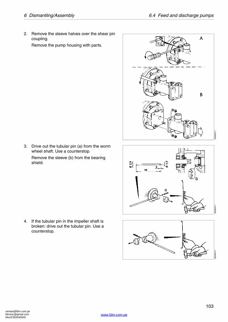
[email protected]@gmail.comMovil:959440045
103
6 Dismantling/Assembly 6.4 Feed and discharge pumps
2. Remove the sleeve halves over the shear pin coupling.
Remove the pump housing with parts.
3. Drive out the tubular pin (a) from the worm wheel shaft. Use a counterstop.
Remove the sleeve (b) from the bearing shield.
4. If the tubular pin in the impeller shaft is broken: drive out the tubular pin. Use a counterstop.
G05
9421
1G
0594
311
G05
9441
1
www.fdm.com.pe

[email protected]@gmail.comMovil:959440045
6.4 Feed and discharge pumps 6 Dismantling/Assembly
104
5. Check that the lipseal ring (c) is faultless.
Should this not be the case, fit a new ring, turned the right way.
Fit the new shear pin coupling (d) in the worm wheel shaft together with the sleeve (b). Drive the tubular pin (a) into its position. Use a counterstop.
6. Check that the impeller shaft can be revolved by hand.
Should this not be the case: dismantle the pump and check the parts. See ‘‘6.4.1 Exchange of shear pin coupling” on page 102.
Drive in a new tubular pin if the old one is broken. Use a counterstop.
G05
9451
1G
0594
611
www.fdm.com.pe

[email protected]@gmail.comMovil:959440045
105
6 Dismantling/Assembly 6.4 Feed and discharge pumps
7. Fit the pump housing with parts. Be careful not to damage the lipseal ring.
Fit the sleeve halves over the shear pin coupling.
8. Put down the control housing with connecting piece and the lower gasket.
Tighten the screws.
Fit the sight glass and the upper gasket. Screw on the lock ring.
Fasten the pipe connections of the pump.
G05
9471
1G
0594
811
www.fdm.com.pe

[email protected]@gmail.comMovil:959440045
6.5 Oil filling 6 Dismantling/Assembly
106
6.5 Oil filling
1. Place a collecting tray under the drain hole, remove the drain plug to drain off the oil.
2. Fill new oil in the worm gear housing. The oil level should be slightly above middle of the sight glass. For lubricating oil volume see chapter ‘‘8 Technical Reference” on page 119.
NOTEBefore adding or renewing lubricating oil in the worm gear housing, the information concerning different oil groups, handling of oils, oil change intervals etc. given in chapter ‘‘8 Technical Reference” on page 119 must be well known.
CAUTION
Burn hazards
Lubricating oil and various machine surfaces can be sufficiently hot to cause burns.
G06
0261
1G
0602
711
www.fdm.com.pe

[email protected]@gmail.comMovil:959440045
107
6 Dismantling/Assembly 6.6 Brake
6.6 Brake
6.6.1 Checking of brake plug
A worn or oily brake plug will lengthen the stopping time. Remove the bracket with the brake. Examine the friction element.
� Replace the plug when the friction material is worn. If the thickness A of the friction material is less than 0,5 mm the brake plug need to be replaced.
� If the friction element is oily: clean the brake plug and the outside surface of the bowl body with a suitable degreasing agent.
Checking the brake
After the brake assembly has been fitted, release the brake and rotate the bowl slowly by hand. If a scraping noise is heard, the friction element is probably touching the bowl surface.
For normal stopping time see ‘‘8.2 Technical data” on page 121.
G05
9311
1
Maximum wear of brake plug when A=0,5 mm
www.fdm.com.pe

[email protected]@gmail.comMovil:959440045
6.7 Frame feet 6 Dismantling/Assembly
108
6.7 Frame feetWhen replacing the frame feet, the separator must be lifted.
See ‘‘5.7 Lifting instructions” on page 79.
When lifting and moving the separator, follow normal safety precautions for lifting large heavy objects.
6.7.1 Mounting of new frame feet
1. Remove the existing frame feet.
2. Mount the new feet. Tightening torque 16 Nm. Secure the bolt with the lock-nut.
3. Place the separator in its original position and assemble the separator.
4. Remove the two eye bolts used for lifting.
NOTE
Always remove the bowl before lifting the separator.
G06
0531
1
Frame foot with vibration damping
www.fdm.com.pe

[email protected]@gmail.comMovil:959440045
109
7 Trouble-tracing
Contents
7.1 Trouble tracing procedure 110
7.2 MAB mechanical function 110
7.2.1 The separator does not start 110
7.2.2 Start-up time too long 110
7.2.3 Starting power too low 111
7.2.4 Starting power too high 111
7.2.5 Separator vibrates�excessively during�starting sequence 112
7.2.6 Separator vibrates�excessively during�normal running 112
7.2.7 Smell 113
7.2.8 Noise 113
7.2.9 Speed too high 113
7.2.10 Speed too low 114
7.2.11 Stopping time too long 114
7.2.12 Water in oil sump 114
7.2.13 Liquid flows through bowl�casing drain 115
7.3 Purification faults 116
7.3.1 Unsatisfactory separation�result 116
7.3.2 Outgoing water contaminated�by oil 116
7.3.3 Broken water seal 117
7.4 Clarification faults 118
7.4.1 Unsatisfactory separation result 118
7.4.2 Oil discharge through�water outlet 118
Study theSystem Manual’sTrouble-tracing
chapter first.(if applicable)
If the problem is not solved in the System Manual’s
Trouble-tracing, continue with this chapter.
Trouble-tracing
www.fdm.com.pe

[email protected]@gmail.comMovil:959440045
7.1 Trouble tracing procedure 7 Trouble-tracing
110
7.1 Trouble tracing procedure
This chapter applies to trouble-tracing concerning functions of the separator only. It does not include the other equipment in your processing system.
Always start with trouble-tracing instructions in the System Manual, and if required, continue with the instructions below. If the problem still is not solved, contact your Alfa Laval representative.
7.2 MAB mechanical function
7.2.1 The separator does not start
7.2.2 Start-up time too long
Possible cause Action
No power supply to motor. Check power supply.
Bowl lock screws stops rotation. Release lock screws.
Possible cause Action
Brake applied. Release brake.
Friction pads worn or oily. Fit new friction pads.
Motor failure. Repair.
Incorrect power supply (50 Hz instead of 60 Hz).
Use correct power supply. See machine plate.
Bearings damaged or worn. Install new bearings.
www.fdm.com.pe

[email protected]@gmail.comMovil:959440045
111
7 Trouble-tracing 7.2 MAB mechanical function
7.2.3 Starting power too low
7.2.4 Starting power too high
Possible cause Action
Motor failure. Repair the motor.
Friction pads worn. Fit new friction pads.
Friction pads oily. Fit new friction pads.
Possible cause Action
Bowl lock screws stops rotation. Release lock screws.
Brake is on. Release brake.
Motor failure. Repair the motor.
Gear worn out. Replace worm wheel and worm.
Bearing damaged or worn. Install new bearings.
Incorrect transmission (50 Hz gear and 60 Hz power supply).
DANGER: Disintegration hazard
STOP immediately! Install correct transmission.
Contact your local Alfa Laval representative. The bowl must be inspected.
Wrong direction of rotation. STOP. Adjust motor power connection.
www.fdm.com.pe

[email protected]@gmail.comMovil:959440045
7.2 MAB mechanical function 7 Trouble-tracing
112
7.2.5 Separator vibrates excessively during�starting sequence
7.2.6 Separator vibrates excessively during�normal running
NOTE Some vibration is normal during starting �sequence when the separator passes through its �critical speeds.
Possible cause Action
Bowl out of balance due to:
poor cleaning
incorrect assembly WARNING: Disintegration hazard
too few discs
insufficiently tightened bowl hood STOP immediately! Identify and rectify cause.
bowl assembled with parts from other separators.
Vibration dampers in frame feet worn out. Fit new vibration dampers.
Bowl spindle bent (max. 0,15 mm). Fit a new bowl spindle.
Top and/or bottom bearing damaged or worn.
Fit new bearings.
Top bearing springs defective. Fit new springs.
Possible cause Action
Uneven sludge deposits in sludge space. STOP and clean bowl.
Bearings damaged or worn. Fit new bearings.
Vibration-damping rubber washers worn out.
Fit new frame feet washers every four years.
Spindle top bearing spring(s) broken. Replace all springs.
www.fdm.com.pe

[email protected]@gmail.comMovil:959440045
113
7 Trouble-tracing 7.2 MAB mechanical function
7.2.7 Smell
7.2.8 Noise
7.2.9 Speed too high
Possible cause Action
Normal occurrence during start as the (new) friction blocks slip.
None.
Brake is applied. Release the brake.
Top and/or bottom bearing overheated. Fit new bearings.
Possible cause Action
Oil level in oil sump is too low. STOP and read oil level and add oil.
Top and/or bottom bearing damaged or worn.
Fit new bearings.
Friction pads worn. Fit new friction pads.
Possible cause Action
Incorrect transmission (50 Hz gear running on 60 Hz power supply).
DANGER: Disintegration hazard
STOP immediately! Install correct transmission.
Contact your local Alfa Laval representative. The bowl must be inspected.
Frequency of power supply too high. Check.
www.fdm.com.pe

[email protected]@gmail.comMovil:959440045
7.2 MAB mechanical function 7 Trouble-tracing
114
7.2.10 Speed too low
7.2.11 Stopping time too long
7.2.12 Water in oil sump
Possible cause Action
Brake is on. Release the brake.
Friction pads worn or oily. Fit new friction pads or clean the old ones if they are oily.
Motor failure. Repair the motor.
Top/bottom bearings damaged or worn. Fit new bearings.
Bearing overheated/damaged. Fit new bearings.
Incorrect transmission (60 Hz gear running on 50 Hz current).
Make sure that the gear is intended for 50 Hz power supply.
Possible cause Action
Brake lining worn or oily. Fit new friction pads or clean the old ones if they are oily.
Possible cause Action
Bowl casing drain obstructed. Clean. Change oil.
Leakage at top bearing. Fit a new seal ring and change oil.
Condensation. Clean the oil sump. Change oil.
www.fdm.com.pe

[email protected]@gmail.comMovil:959440045
115
7 Trouble-tracing 7.2 MAB mechanical function
7.2.13 Liquid flows through bowl�casing drain
Possible cause Action
Broken water seal. Stop feed and feed water to create water seal.
Too high throughput Reduce the feed.
The supply of displacement/ sealing water is not sufficient due to clogged strainer, kinked hose or low water pressure.
Straighten the hose or clean the strainer. Make sure the water pressure is 200-600 kPa (2-6 bar).
Seal ring on gravity/clarifier disc defective.
Fit a new seal ring.
Bowl hood seal ring defective. Fit a new seal ring.
Bowl speed too low. Make sure current is on and brake is off. Inspect motor and power transmission.
www.fdm.com.pe

[email protected]@gmail.comMovil:959440045
7.3 Purification faults 7 Trouble-tracing
116
7.3 Purification faults
7.3.1 Unsatisfactory separation�result
7.3.2 Outgoing water contaminated by oil
Possible cause Action
Gravity disc hole too small. Use a gravity disc with a larger hole.
Incorrect separating temperature. Adjust temperature.
Throughput too high. Reduce throughput.
Sludge space in bowl is filled. Empty the sludge basket in the bowl.
Disc stack clogged. Clean the bowl discs.
Bowl speed too low. See ‘‘7.2.10 Speed too low” on page 114.
Possible cause Action
Gravity disc hole too large. Use a gravity disc with a smaller hole.
Seal ring under the gravity disc defective. Fit a new seal ring.
www.fdm.com.pe

[email protected]@gmail.comMovil:959440045
117
7 Trouble-tracing 7.3 Purification faults
7.3.3 Broken water seal
Possible cause Action
Gravity disc too large. Use a gravity disc with a smaller hole.
Separation temperature too low. Increase temperature.
Throughput too high. Reduce throughput.
Sealing water volume too small. Supply more water.
Seal ring under gravity disc defective. Fit a new seal ring.
Disc stack clogged. Clean the bowl discs.
Bowl speed too low. Use correct speed. See ‘‘7.2.10 Speed too low” on page 114.
Bowl incorrectly assembled. Examine and make correct.
www.fdm.com.pe

[email protected]@gmail.comMovil:959440045
7.4 Clarification faults 7 Trouble-tracing
118
7.4 Clarification faults
7.4.1 Unsatisfactory separation result
7.4.2 Oil discharge through water outlet
Possible cause Action
Separating temperature too low. Adjust.
Throughput too high. Reduce throughput.
Feed oil contains water. Re-assemble and operate the separator as a purifier.
Disc stack clogged. Clean the bowl discs.
Sludge space in bowl filled. Empty the sludge basket.
Bowl speed too low. See ‘‘7.2.10 Speed too low” on page 114.
Possible cause Action
Valve(s) in outlet line closed. Open the valve(s) and adjust to normal back pressure.
Disc stack clogged. Clean the bowl discs.
Seal ring under gravity disc is defective. Fit a new seal ring.
Bowl incorrectly assembled. Examine and make correct.
www.fdm.com.pe

[email protected]@gmail.comMovil:959440045
119
8 Technical Reference
Contents
8.1 Product description 120
8.2 Technical data 121
8.2.1 Gravity disc nomogram 124
8.3 Basic size drawing 126
8.3.1 Dimensions of connections 127
8.4 Basic size drawing, for heater 128
8.4.1 Dimensions of connections 129
8.5 Connection list 130
8.6 Connection list, for heater 131
8.7 Interface description 132
8.7.1 Definitions 132
8.7.2 Component description�and signal processing 133
8.7.3 Function graph and�running limitations 134
8.8 Lubricants 135
8.8.1 Lubrication chart, general 135
8.8.2 Recommended lubricating oils 137
8.8.3 Recommended oil brands (01) 138
8.8.4 Recommended oil brands (02) 140
8.8.5 Recommended oil brands (03) 142
8.8.6 Lubricants 144
8.9 Drawings 148
8.9.1 Cross-section of separator 148
8.9.2 Exploded view 149
8.9.3 Water adding device (option) 150
8.9.4 Pump 151
8.9.5 Foundation drawing 152
8.9.6 Lifting instruction 153
8.9.7 Electric motor 154
8.9.8 Electric motor 156
8.9.9 Electric motor 158
8.10 Lock switch 160
8.10.1 Switch 161
8.10.2 Machine plates and�safety labels 162
8.11 Storage and installation 164
8.11.1 Storage and transport of goods 164
8.11.2 Planning and installation 166
8.11.3 Foundations 169
www.fdm.com.pe
[email protected]@gmail.comMovil:959440045
8.1 Product description 8 Technical Reference
120
8.1 Product descriptionAlfa Laval ref. 553692-06 rev. 9
Units according to ISO Standard.
The manufacturer reserves the right to change specifications without notice.
Product number: 881145-09-01/7
Separator type: MAB 103B-24
Application: Mineral oil
Technical Design:: Purifier/clarifier with solid-wall separator bowl and collecting cover in�aluminium.Sealings available in NITRILE.Intended for marine- and land applications.
Designed in accordance with standards:
98/37 EEC
91/368 EEC 93/44 EEC
The Council Directive of the European Communities(CE-marking is possible if manual is included in the�delivery).
EN 12100-1 Safety of machines. Use of the machine in applications subject to hygienic demands requires a well adapted cleaning program.
Restrictions:
Feed temperature: 0 - 100 �C
Ambient temperature: 5 - 55 �C
Not to be used for liquids with flashpoint below 60 �C
Risk for corrosion and erosion has to be investigated in each case by the application centre.
www.fdm.com.pe

[email protected]@gmail.comMovil:959440045
121
8 Technical Reference 8.2 Technical data
8.2 Technical dataAlfa Laval ref. 556001 rev. 1
Units according to ISO Standard.
The manufacturer reserves the right to change specifications without notice.
Bowl speed max: 8571/ 8600 rev/min. 50Hz/60Hz
Speed motor shaft max: 1500/1800 rev/min. 50Hz/60Hz
Gear ratio: 40:7/43:9 50Hz/60Hz
Hydraulic capacity: 1,40 m³/h
Max. density of sediment/feed: 5000/1100 kg/m³
Feed temperature: 0/100 min./max.��C
Weight of separator: 75,2 kg (without motor)
Motor power: 0,75 kW
Jp reduced to motor shaft: 1,60 kg/m² 50Hz
Jp reduced to motor shaft: 1,10 kg/m² 60Hz
Max. power consumption: 0,6 kW (at starting up)
Power consumption: 0,4/0,6 kW (idling/at max. capacity)
Lubricating oil volume: 0,7 litres
Starting time: 3,0 minutes (min. / max.)
Stopping time with brake: 2,0/2,5 minutes (min. / max.)
Stopping time without brake: 6,0 minutes (average)
Max. running time;
empty bowl: 480 minutes
filled bowl: 480 minutes
Sound power/sound pressure level.
7,6 /64 Bel(A) /dB(A)
Vibration level, separator in use 9,0 mm/sec (r.m.s)
Bowl max. inner diameter 159 mm
Bowl volume 1,2 litres
Bowl weight 13 kg
Bowl body material AL 111 2377-02
There are other material than stainless steel in contact with process fluid.
www.fdm.com.pe

[email protected]@gmail.comMovil:959440045
8.2 Technical data 8 Technical Reference
122
www.fdm.com.pe

[email protected]@gmail.comMovil:959440045
123
8 Technical Reference 8.2 Technical data
G05
9951
1
Power consumption at startup, power input vs time
www.fdm.com.pe

[email protected]@gmail.comMovil:959440045
8.2 Technical data 8 Technical Reference
124
8.2.1 Gravity disc nomogramAlfa Laval ref. 556414 rev. 0
��= Density of oil in kg/m3 at 15 °C Q = Thoughput in m3/hT = Separating temperature in °C or °F
20
60 70 80 90 100 110 120 130 140 150 160 170 180 190 200 212
800
850
900
950
991
1000
30 40 50 60 70 80 90 100T( C)
T( F)
Q (m³/h)
ρ (kg/m³)
I
0,2 0,4 0,6 0,8 1 1,2 1,4
I
I
46
47,5
49
51
54
58
63
69
G06
1191
1
www.fdm.com.pe

[email protected]@gmail.comMovil:959440045
125
8 Technical Reference 8.2 Technical data
Selection of gravity disc
The best separating results are obtained by using a gravity disc with as large a hole as possible, one which will not cause a broken water seal in the bowl or an emulsification in the water outlet.
The presence of salt water may demand the use of gravity disc with bigger hole than indicated in the nomogram (the nomogram is based on the density properties of fresh water).
Example I in nomogram
Density of oil 980kg/m3 at 15 °C
Separating temp. 98 °C
Troughput 0,4 m3/h
Hole diameter ��47,5 mm
Example II in nomogram
Density of oil 886kg/m3 at 15 °C
Separating temp. 90 °C
Troughput 1,2 m3/h
Hole diamete ��63 mm
www.fdm.com.pe

[email protected]@gmail.comMovil:959440045
8.3 Basic size drawing 8 Technical Reference
126
8.3 Basic size drawingAlfa Laval ref. 556939 rev. 0
A. Screw 3/8-16UNCB. Tightening torque 16 Nm locked with lock nut
Data for connections see ‘‘8.5 Connection list” on page 130.
390
270
201
25062
895
360
565 221
460
380
155
115 45
170
335
178
170
230 207
75
220
6019
A
B
206
701
760
G05
9143
1
www.fdm.com.pe
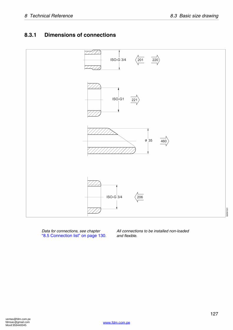
[email protected]@gmail.comMovil:959440045
127
8 Technical Reference 8.3 Basic size drawing
8.3.1 Dimensions of connections
Data for connections, see chapter �‘‘8.5 Connection list” on page 130.
All connections to be installed non-loaded and flexible.
ISO-G1
35
ISO-G 3/4
o
ISO-G 3/4 206
201 220
221
460
G05
9153
1
www.fdm.com.pe

[email protected]@gmail.comMovil:959440045
8.4 Basic size drawing, for heater 8 Technical Reference
128
8.4 Basic size drawing, for heater
Alfa Laval ref. 556928 rev. 0
A. Screw 3/8-16UNCB. Tightening torque 16 Nm
locked with lock nut.
Data for connections see ‘‘8.6 Connection list, for heater” on page 131.
A
B
G05
9162
1
www.fdm.com.pe

[email protected]@gmail.comMovil:959440045
129
8 Technical Reference 8.4 Basic size drawing, for heater
8.4.1 Dimensions of connections
Data for connections, see chapter �‘‘8.5 Connection list” on page 130.
All connections to be installed non-loaded and flexible.
G05
9163
1
www.fdm.com.pe

[email protected]@gmail.comMovil:959440045
8.5 Connection list 8 Technical Reference
130
8.5 Connection listAlfa Laval ref. 556989 rev. 0
Connection No. Description Requirements/limit
201 Inlet for process liquid, (to pump)�- Permitted temperatures
�max. 100 °C, min. 0 °C
206 Inlet for water seal Fresh water, approx 1litre (depending on gravity disc)
220 Outlet for light phase (oil from pump)
221 Outlet for heavy phase (water) no counter pressure
460 Drain of frame
701 Motor for separator�- Max. deviation from nominal frequency
�±5%
760 Cover interlocking switch (delivered as option)
Type: Double, two-way microswitch
Switch rating: Voltage Max. 500 V
Current Max. 3 A
www.fdm.com.pe

[email protected]@gmail.comMovil:959440045
131
8 Technical Reference 8.6 Connection list, for heater
8.6 Connection list, for heater
Alfa Laval ref. 556986 rev. 0
Machine with Pre-Heater.
Connection No. Description Requirements/limit
201.1 Inlet for process liquid, (to pump)
- Permitted temperatures max. 100 °C, min. 0 °C
201.2 Outlet for process liquid, (from pump to heater)
201.1 Inlet for process liquid, (from pump to separator)
206 Inlet for water seal Fresh water, approx. 1litre (depending on gravity disc)
220 Outlet for light phase (oil from pump)
221 Outlet for heavy phase (water) no counter pressure
460 Drain of frame
701 Motor for separator
- Max. deviation from nominal frequency ±5%
760 Cover interlocking switch (delivered as option)
Type: Double, two-way microswitch
Switch rating: Voltage Max. 500 V
Current Max. 3 A
www.fdm.com.pe

[email protected]@gmail.comMovil:959440045
8.7 Interface description 8 Technical Reference
132
8.7 Interface descriptionAlfa Laval ref. 557119 rev. 2
In addition to the Connection List this document describes limitations and conditions for safe control, monitoring and reliable operation.
At the end of the document a function graph and running limitations are to be found.
8.7.1 Definitions
Ready for start means:
� The machine is assembled correctly.
� All connections are installed according to Connection List, Interconnection Diagram and Interface Description.
Start means:
� The power to the separator is on.
� The acceleration is supervised to ensure that a certain speed has been reached within a certain time. See ‘‘8.2 Technical data” on page 121.
Normal stop means:
� Stopping of the machine at any time with feed or safety/backup liquid and with brake applied.
www.fdm.com.pe

[email protected]@gmail.comMovil:959440045
133
8 Technical Reference 8.7 Interface description
Safety stop means:
The machine must be stopped in the quickest and safest way due to vibrations or process reasons.
Comply to following conditions:
� The bowl must be kept filled.
� The machine must not be restarted before the reason for the Safety stop has been investigated and action has been taken.
In case of emergency condition in the plant, the machine must be stopped in a way that is described in EN 418.
8.7.2 Component description and signal processing
Separator motor 701
The separator is equipped with a 3-phase DOL-started (direct on line) motor. The separator can also be started by a Y/D starter, but then the time in Y-position must be maximized to 5 seconds.
Cover interlocking switch 760 (option)
The cover of the separator is equipped with an interlocking switch. When the cover is closed the interlocking circuit in the starter control is closed and the separator could be started.
Signal processing:
The circuit is closed when the collecting cover of the separator is closed.
The interlocking switch should be connected so that starting of the motor is prevented when the separator collecting hood is not closed.
www.fdm.com.pe

[email protected]@gmail.comMovil:959440045
8.7 Interface description 8 Technical Reference
134
8.7.3 Function graph and running limitations
G05
4321
1
A Stand stillB Starting modeC Running modeD Stop modeE Safety stop mode
www.fdm.com.pe

[email protected]@gmail.comMovil:959440045
135
8 Technical Reference 8.8 Lubricants
8.8 Lubricants
8.8.1 Lubrication chart, generalAlfa Laval ref. 553216-01, rev. 6
Lubricating points Type of lubricant
Bowl spindle ball bearings and buffers are lubricated by oil mist
Lubricating oil as specified in “Recommended lubricating oils”
Bowl spindle taper Lube oil, only a few drops for rust protection
Metal buffers of bowl spindle Lube oil
Bowl:Sliding contact surfaces and pressure loaded surfaces such as lock rings, threads of lock rings, bowl hood and cap nut
Pastes as specified in “Lubricants”
Rubber seal rings Grease as specified in “Lubricants”
Friction coupling ball bearings The bearings are packed with grease and sealed and need no extra lubrication
Electric motor Follow manufacturer's instructions
Alfa Laval Lubricating Oil Groups
� Group A oil: a high quality gear oil on paraffin base with stable AW (anti wear) additives.
� Group B oil: a high quality gear oil on paraffin base with stable EP (extreme pressure) additives.
� Group D oil: a synthetic base oil with additives stable at high operating temperatures.
� Group E oil: Characteristics as a group D-oil but suitable at a higher operation power (�55 kW)
Do not mix different oil brands or oils from different oil groups.
Always use clean vessels when handling lubricating oil.
Great attention must be paid not to contaminate the lubricating oil. Of particular importance is to avoid mixing of different types of oil. Even a few drops of motor oil mixed into a synthetic oil may result in severe foaming.
Any presence of black deposits in a mineral type oil is an indication that the oil base has deteriorated seriously or that some of the oil additives have precipitated. Always investigate why black deposits occurs.If it is necessary to change from one group of oil brand to another it is recommended to do this in connection with an overhaul of the separator. Clean the gear housing and the spindle parts thoroughly and remove all deposits before filling the new oil.
www.fdm.com.pe

[email protected]@gmail.comMovil:959440045
8.8 Lubricants 8 Technical Reference
136
NOTEAlways clean and dry parts (also tools) before lubricants are applied.
CAUTION
Check the oil level before start. Top up when necessary. Oil volume = see “Technical Data”.
It is of utmost importance to use the lubricants recommended in our documentation.
This does not exclude, however, the use of other brands, provided they have equivalently high quality properties as the brands recommended. The use of oilbrands and other lubricants than recommended, is done on the exclusive responsibility of the user or oil supplier.
Applying, handling and storing of lubricants
Always be sure to follow lubricants manufacturer's instructions.
www.fdm.com.pe

[email protected]@gmail.comMovil:959440045
137
8 Technical Reference 8.8 Lubricants
8.8.2 Recommended lubricating oils
Alfa Laval ref. 553219-10 rev. 0
Three different groups of lubricating oils are approved for type of frame B 1200, B 1300, B 1400 with motor <3,7 kW.
They are designated as Alfa Laval lubricating oil groups A,B and D.
The numerical value after the letter states the viscosity grade.
The corresponding commercial oil brands according to ‘‘Alfa Laval ref. 553218-02 rev. 4” on page 140.
Note:
� In a new installation or after change of gear transmission, change oil after 200 operating hours.
� When the separator is operated for short periods, lubricating oil must be changed every 12 months even if the total number of operating hours is less than stated in the recommendations above.
� Check and prelubricate spindle bearings on separators which have been out of service for 6 months or longer.
� In seasonal operation: change oil before every operating period.
Ambient temperature °C Alfa Laval lubricating oil group
Time in operation Oil change interval
between +5 and +45 A/220 B/220 1500 h
between ±2 and +65 D/220 2000 h
www.fdm.com.pe

[email protected]@gmail.comMovil:959440045
8.8 Lubricants 8 Technical Reference
138
8.8.3 Recommended oil brands (01)
Alfa Laval ref. 553218-01, rev.3
Paraffinic mineral lubricating oil for general use
The list of recommended oil brands are not complete. Other oil brands may be used as long as they have equivalently quality as the brands recommended. The oil shall follow the requirements in one of the standards below. The oil must also be endorsed for worm gear with brass worm wheel. The use of other lubricants than the recommended is done on the exclusive responsibility of the user or oil supplier.
NOTE
The following is a list of recommended oil brands. �Trade names and designations might vary from country to country, Please contact your local supplier for more information.
Alfa Laval lubrication oil group A
Viscosity grade VG (ISO 3448/3104)Viscosity index VI (ISO 2909)
VG 220VI >90
Manufacturer Designation
BP Bartran 220�Bartran HV 220
Castrol Alpha ZN 220Ultra 220
ChevronTexaco Rando HD 220Paper Machine Oil Premium 220
ExxonMobil Mobil DTE oil BB
Q8/Kuwait Petroleum Wagner 220
Shell Morlina 220
Statoil LubeWay XA 220
Total Cirkan ZS 220
www.fdm.com.pe
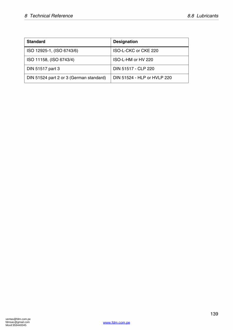
[email protected]@gmail.comMovil:959440045
139
8 Technical Reference 8.8 Lubricants
Standard Designation
ISO 12925-1, (ISO 6743/6) ISO-L-CKC or CKE 220
ISO 11158, (ISO 6743/4) ISO-L-HM or HV 220
DIN 51517 part 3 DIN 51517 - CLP 220
DIN 51524 part 2 or 3 (German standard) DIN 51524 - HLP or HVLP 220
www.fdm.com.pe

[email protected]@gmail.comMovil:959440045
8.8 Lubricants 8 Technical Reference
140
8.8.4 Recommended oil brands (02)
Alfa Laval ref. 553218-02 rev. 4
Paraffinic mineral lubricating oil, category (ISO-L-) CKE 220.
NOTE
The following is a list of recommended oil brands. Trade names and designations might vary from country to country. Please contact your local oil supplier for more information.
Alfa Laval lubrication oil group B
Viscosity grade VG (ISO 3448/3104)Viscosity index VI (ISO 2909)
VG 220VI 90
Manufacturer Designation
Bel-Ray 100 Gear Oil 90
BP Energol GR-XP 220
Castrol Alpha SP 220(Former Optimol) Optigear BM 220
ChevronTexaco Gear Compound EP 220 (H2)Ultra Gear 220 (H2)Texaco/Caltex Meropa 220
ExxonMobil Spartan EP 220Mobilgear 630Mobilgear SHC (XMP)220, Synthetic *
Q8/Kuwait Petroleum Goya 220
Shell Omala 220Omala RL 220, Synthetic *
Statoil LoadWay EP 220Mereta 220, Synthetic *
Total Carter EP 220Elf Epona Z 220Carter SH 220, Synthetic *
*) These oils must be used when the frame temperature is above 80 °C.�If the temperature can’t be measured, a rough estimate is that 80 °C is �when one can touch the surface of lower part of frame only for a short time.
www.fdm.com.pe

[email protected]@gmail.comMovil:959440045
141
8 Technical Reference 8.8 Lubricants
The list of recommended oil brands are not complete. Other oil brands may be used as long as they have equivalently quality as the brands recommended. The oil must have the same viscosity class and shall follow the requirements in one of the standards below. The oil must also be endorsed for worm gear with brass worm wheel. The use of other lubricants than the recommended is done on the exclusive responsibility of the user or oil supplier.
Standard Designation
ISO 12925-1, (ISO 6743/6) ISO-L-CKC/CKD/CKE/CKT 220
DIN 51517 part 3 DIN 51517 - CLP 220
www.fdm.com.pe

[email protected]@gmail.comMovil:959440045
8.8 Lubricants 8 Technical Reference
142
8.8.5 Recommended oil brands (03)
Alfa Laval ref. 553218-03 rev. 5
Synthetic lubricating oil, category PAO (ISO-L-) CKE 220
Viscosity grade (ISO 3448/3104) VG 220.
The following are lists of recommended oil brands. Trade names and designations might vary from country to country, contact your local oil supplier for more information.
Brands with Alfa Laval article number are approved and recommended for use.
Alfa Laval lubrication oil group D
Manufacturer Designation
Alfa Laval 542690-84 20 litres replacement for 542690-80542690-85 4 litres replacement for 542690-81
BP Enersyn HTX 220Enersyn EP-XF 220
Castrol Alphasyn EP 220Alphasyn HG 220Optigear Synthetic A 220
Chevron Tegra Synthetic Gear Lubricant 220 (H2)Texaco/Caltex Pinnacle EP 220FAMM Pinnacle Marine Gear 220
ExxonMobil Mobil SHC 630
Q8/Kuwait Petroleum Schumann 220
Shell Omala RL 220
Statoil Mereta 220
Total Carter SH 220Elf Epona SA 220
The lists of recommended oil brands are not complete. Other oil brands may be used as long as they have equivalently quality as the brands recommended. The oil must have the same viscosity class and ought to follow the ISO standard 12925-1, category ISO-L-CKC, CKD, CKE or CKT (ISO 6743-6) or DIN 51517, part 3 CLP, but shall have a synthetic base oil of polyalphaolefin type (PAO) instead of mineral base oil. The oil must be endorsed for worm gear with brass worm wheel. The use of other lubricants than recommended is done on the exclusive responsibility of the user or oil supplier.
www.fdm.com.pe

[email protected]@gmail.comMovil:959440045
143
8 Technical Reference 8.8 Lubricants
Synthetic lubricating oil, category PAO (ISO-L-) CKE 220 for �hygienic applications
Conform to U.S. Food and Drug Administration (FDA) requirements of lubricants with �incidental food contact, Title CRF 21 178.3570, 178.3620 and/or those generally regarded �as safe (US 21 CRF 182).
Lubrication oils for food and hygienic applications
Manufacturer Designation
Shell Cassida fluid GL 220
The hygienic oil on the list is in the online “NSF White BookTM Listing” at the time of the�revision of this document. For more information about the NSF registration and up to date�H1 registration, see www.nsf.org (http://www.nsf.org/business/nonfood_compounds/)
www.fdm.com.pe

[email protected]@gmail.comMovil:959440045
8.8 Lubricants 8 Technical Reference
144
8.8.6 LubricantsAlfa Laval ref. 553217-01, rev. 11
Pastes:
Bonded coatings:
NOTE
The data in the below tables is based on supplier information in regards to lubrication properties.
Trade names and designations might vary from country to country. Please contact your local supplier for more information.
Brands with Alfa Laval article number are approved and recommended for use.
Manufacturer Designation Alfa Laval No
Dow Corning Molykote 1000 (Paste) 537086-02 (1000 g)
Molykote 1000 (Paste) 537086-03 (100 g)
Molykote G-rapid plus (Paste) 537086-04 (50 g)
Fuchs Lubritech Gleitmo 705
Gleitmo 805K
Klüber Wolfracoat C (Paste)
Rocol Dry Moly PasteMT-LM
Manufacturer Designation Alfa Laval No
Dow Corning Molykote D321R (Spray) 535586-01 (375 g)
Fuchs Lubritech Gleitmo 900 (Varnish or spray)
www.fdm.com.pe

[email protected]@gmail.comMovil:959440045
145
8 Technical Reference 8.8 Lubricants
Pastes for hygienic applications (NSF registered H1 is preferred):
Manufacturer Designation Hygienic comment Alfa Laval No
Dow Corning Molykote P1900 NSF Registered H1 (7 Jan 2004)
Molykote TP 42
Molykote D
Bremer & Leguil, Fuchs Lubritech
Geralyn F.L.A. NSF Registered H1 (2 April 2003) German § 5 Absatz 1 LMBG approved
Geralyn 2 NSF Registered H1 (3 Sep 2004)
561764-01 (50g)
Gleitmo 805 DVGW (KTW) approval for drinking water (TZW prüfzeugnis)
Gleitmo 1809 554336-01
Klüber Klüberpaste UH1 96-402
NSF Registered H1 (25 Feb 2004)
Klüberpaste UH1 84-201
NSF Registered H1 (26 Aug 2005)
Klüberpaste 46 MR 401
White; contains no lead, cadmium, nickel, sulphur nor halogens.
Rocol Foodlube Multi Paste
NSF Registered H1 (13 Apr 2001)
www.fdm.com.pe

[email protected]@gmail.comMovil:959440045
8.8 Lubricants 8 Technical Reference
146
Silicone grease for rubber rings:
Manufacturer Designation Hygienic comment Alfa Laval No.
Dow Corning (Molykote) 111 (Compound)
Conform to the FDA regulations (21 CFR 178.3570) for occasional food contact. Certified: National Water Council UK and WRC, UK. Certified: food industry as per Chemical Testing Laboratory Dr. Böhm, Munich.
539474-02 (100 g)
539474-03 (25 g)
Molykote G-5032 NSF Registered H1 (June 3 2005)
569415-01 (50 g)
Bremer & Leguil,Fuchs Lubritech
Chemplex 750 DVGW approved according to the German KTW-recommendations for drinking water.
Geralyn SG MD 2 NSF Registered H1 (30 March 2007)
Klüber Unisilkon L 250 L Complies with German Environmental Agency on hygiene requirements for tap water. Certified by DVGW-KTW, WRC, AS4020, ACS.
Paraliq GTE 703 NSF Registered H1 (25 Feb 2004)Complies with LMBG and the European standard EN 1672, part 2.
Bel-Ray No-Tox Silicone Valve Seal
NSF Registered H1 (19 June 2002)
MMCC ALCO 220 NSF Registered H1 (25 March 2002)
Rocol Foodlube Hi-Temp
NSF Registered H1 (18 April 2001)
www.fdm.com.pe

[email protected]@gmail.comMovil:959440045
147
8 Technical Reference 8.8 Lubricants
Greases for ball and roller bearings:
NOTEAlways follow the specific recommendation for lubrication as advised by the manufacturer.
Manufacturer Designation Hygienic comment
BP Energrease MP-MG2
Energrease LS2
Energrease LS-EP2
Castrol APS 2 Spheerol EPL 2
Chevron Chevron Dura-Lith Grease EP2 Texaco Multifak AFB 2
Dow Corning Molykote G-0101 Molykote Multilub
ExxonMobil Beacon EP2
Unirex N2
Mobilith SHC 460
Mobilux EP2
Fuchs Lubritech Lagermeister EP2
Q8/Kuwait Petroleum
Rembrandt EP2
Shell Alvania EP 2
Albida EP2
SKF LGEP 2
LGMT 2
LGFB 2 NSF Registered H1 (14 Sept 2005)
Total Multis EP2
BP Energrease MP-MG2
Energrease LS2
Energrease LS-EP2
www.fdm.com.pe

[email protected]@gmail.comMovil:959440045
8.9 Drawings 8 Technical Reference
148
8.9 Drawings
8.9.1 Cross-section of separator
R01
0784
1
Cross-section of separator
www.fdm.com.pe
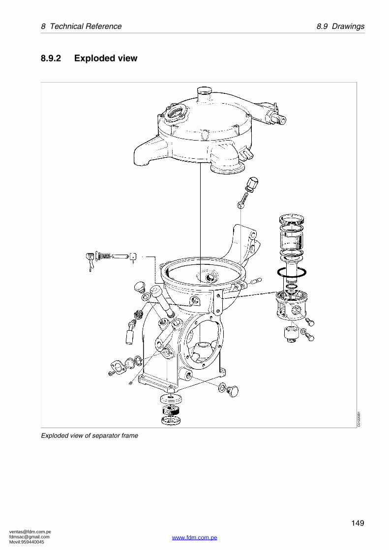
[email protected]@gmail.comMovil:959440045
149
8 Technical Reference 8.9 Drawings
8.9.2 Exploded view
C01
220B
1
Exploded view of separator frame
www.fdm.com.pe

[email protected]@gmail.comMovil:959440045
8.9 Drawings 8 Technical Reference
150
8.9.3 Water adding device (option)
G0877521
www.fdm.com.pe

[email protected]@gmail.comMovil:959440045
151
8 Technical Reference 8.9 Drawings
8.9.4 Pump
C01
221B
1
Inlet and outlet pump, exploded view
G06
0471
1
Inlet and outlet pump, cross-section
Alfa Laval ref. 529209
www.fdm.com.pe

[email protected]@gmail.comMovil:959440045
8.9 Drawings 8 Technical Reference
152
8.9.5 Foundation drawingAlfa Laval ref. 556885 rev. 0
A Center of separator bowlB 4 holes Ø 11,5 for anchorageC Service side
Recommended free floor space for unloading when doing service
Min. access area for overhead hoist (no fixed installation within this area)
Vertical force not exceeding 6 kN/foot
Horizontal force not exceeding 6 kN/foot
220125
30
47.5
2000
2000
80 min.80 min.
1000 1000
V H
A B
CG
0602
131
www.fdm.com.pe

[email protected]@gmail.comMovil:959440045
153
8 Technical Reference 8.9 Drawings
8.9.6 Lifting instructionAlfa Laval ref. 556213 rev. 0
Weight to lift 80 kg
Lifting the separator1. Remove cap nut on hinged bolt2. Remove separator bowl3. Assemble lifting eye nuts on hinged bolt.
NOTE
Never lift the separator with the separator bowl inside.
NOTE
Never lift the separator in any other way.
G05
9135
1
www.fdm.com.pe

[email protected]@gmail.comMovil:959440045
8.9 Drawings 8 Technical Reference
154
8.9.7 Electric motorAlfa Laval ref. 551587 rev. 5
Note! The motor bearings are permanently lubricated.
The rotor balanced with half key. Max. vibration velocity 1,8 nm/s (rms)�according to IEC 34-14.
Manufacturer ABB MotorsManufacture drawing Cat. BA/Marine motors� GB 98-05Standards IEC 34-series, 72, 79, 85.Size IEC 80BType M2AA 80BWeight 10 kgPoles 4Insulation class FBearings D-end 6204-2Z/C3
N-end 6203 2Z/C3Method of cooling IC411 (IEC 34-6)�Totally enclosed 3-phase motor for marine service 3)
Type of mounting
IEC 34-7
Degree of protection
IEC 34-5
IIM 3001
IM 3011
IM 3031
IP 55
A
B
C
G06
0556
1
A Knockout openings for 2 x M20 cable glands on both sides B Sheet-steel fan hoodC 4xØ12
www.fdm.com.pe

[email protected]@gmail.comMovil:959440045
155
8 Technical Reference 8.9 Drawings
1. Ist/I=starting current/rated current at direct on line starting.
2. Thermistors tripping temperature. if applicable
3. The motors can be designed to fulfill requirements�of the following Classification Societies: (Essential Service if required)
Required classification society must always be specified when ordering. Factory test certificate to be enclosed at the delivery. Rated output (kW) valid for temp. rise max 90°C.
4) These motors are provided with heating element for 200V - 240V�according to variant code +451.
Connection to separate terminal board in the main terminal box according to attached connection diagram.
Lloyds Register of Shipping (LR) Nippon Kaiyi Kyokai (NK)
Det Norske Veritas (DnV) Korean Register of Shipping (KR)
Germanischer Lloyd (GL) Po/ski Rejester Statkow (PRS)
Bureau Veritas (BV) China Classification Society (CCS)
American Bureau of Shipping (ABS) Indian Register of Shipping (IRS)
Registro Italiano Navale (RINa) Maritime Register of Shipping (RMS)
NOTE
For complete information about motor variants, please contact your Alfa Laval representative.
www.fdm.com.pe

[email protected]@gmail.comMovil:959440045
8.9 Drawings 8 Technical Reference
156
8.9.8 Electric motorAlfa Laval ref. 53558260 rev. 0
200
97
φ165φ165
45°
265
40 37 100
12 62
26
3.5
φ19j6φ19j6
6h9
15.5
21.5
67
150φ200
φ200
φ130j6
φ130j6
M6
16
110
B AC
G06
0558
1
A PG16. B M20x1,5C 4xØ12
www.fdm.com.pe

[email protected]@gmail.comMovil:959440045
157
8 Technical Reference 8.9 Drawings
Supplier:
Power:
Voltage/Frequency:
Speed:
Type:
Weight:
Efficiency:
Insulation class:
Bearings:
Power factor:
Current:
Torque:
Capacitor:
Moment of inertia:
Enclosure:
Flange mounted motor:
ABB Motors
0,95 kW
200V/50Hz, single phase
1410g/min
M3VD 80 C 3GVD 082003
11,5 kg
73.0 %
F
Totally enclosed
Cos��0,93
In=6,1A Nm; Is/In=4,1
Tn=6,1Nm; Ts/Tn=1,8; Tmax/Tn=1,8
Start: 80F; Run: 16F
J=1/4 GD2; 0,00194 kgm2
IP 55
Im B5
www.fdm.com.pe

[email protected]@gmail.comMovil:959440045
8.9 Drawings 8 Technical Reference
158
8.9.9 Electric motorAlfa Laval ref. 580751 rev. 2
Manufacturer:
Manufacture drawing:
Standards:
Size:
Type:
Weight:
Poles:
Insulation class:
Bearings:
Method of cooling:
Totally enclosed 3-phase motor for marine service 3)
Crompton Greaves Ltd
Cat. Crompton Greaves Lt, TEFC, SCR
IEC 34-series, 72, 79 and 85.
IEC 80
GD80
12 kg
4
F
D-end 6204-2Z
N-end 6003 2Z
IC 411 (IEC 34-6)
A
B
C
G06
0557
1
A Cable entry Ø20. B Sheet-steel fan hoodC 4xØ12
www.fdm.com.pe

[email protected]@gmail.comMovil:959440045
159
8 Technical Reference 8.9 Drawings
The rotor balanced with half key.
Max. vibration velocity 1,8 mm/S (rms) according. to /EC 34-14.
1. Ist / I=starting current/ rated current at direct on line starting.
2. Thermistors tripping tamp. if applicable
3. All ratings can be CSA marked
Factory test certificate to be enclosed at the delivery. Rated output (kW) valid for temperature rise max 80 °C.
Some motors can be provided with space heaters for 230V 60W.
State supply voltage when ordering.
Connection to separate terminal board in the main terminal box according to attached connection diagram.
Type of mounting
IEC 34-7
Degree of protection
IEC 34-5
IIM 3001 IP 55
NOTE
The motor bearings are permanently lubricated.
NOTE
For complete information about motor variants, please contact your Alfa Laval representative.
www.fdm.com.pe

[email protected]@gmail.comMovil:959440045
8.10 Lock switch 8 Technical Reference
160
8.10 Lock switchAlfa Laval ref. 535867, rev. 2
1. SwitchA. Sealed with Loctite 270B. Tube fitted at site
1
A
A B G05
4815
1
www.fdm.com.pe

[email protected]@gmail.comMovil:959440045
161
8 Technical Reference 8.10 Lock switch
8.10.1 SwitchAlfa Laval ref. 530007, rev. 2
A. Max and Min position
1. 500V, GA, P43 (Type:ES11i HRB sGU)
2. 500V, GA, P43 (Type: ES11i + GU)
3. 500V, GA, P43 (Type: ES11il + GU
For other technical information see chapter�‘‘8.5 Connection list” on page 130 and�‘‘8.7 Interface description” on page 132.
23
1
A
G05
4816
1
www.fdm.com.pe

[email protected]@gmail.comMovil:959440045
8.10 Lock switch 8 Technical Reference
162
8.10.2 Machine plates and safety labels
Alfa Laval ref. 549438 rev. 2
1. Machine plate
SeparatorManufacturing serial No / YearProduct NoFrameBowlMax. speed (bowl)Direction of rotation (bowl)Speed motor shaftEl. current frequencyRecommended motor powerMax. density of feedMax. density of sedimentProcess temperature min./max.
G0602821
S00
6141
1
www.fdm.com.pe

[email protected]@gmail.comMovil:959440045
163
8 Technical Reference 8.10 Lock switch
3. Safety label
Text on label:
WARNING:
Read the instruction manuals before installation, operation and maintenance. Consider inspection intervals.
Failure to strictly follow instructions can lead to fatal injury.
If excessive vibration occur, stop separator and keep bowl filled with liquid during rundown.
Out of balance vibration will become worse if bowl is not full during rundown.
Separator must stop rotating before any dismantling work is started.
4. Name plate
6. Power supply frequency
7. Arrow
Indicating direction of rotation of horizontal driving device.
9. Stop, follow lifting instruction
This transport label is not permanently fixed to the separator.
XXXXX XXX XXXX XXXXXXXX XXXX X XXXX XXXXX.
XXX XXX X XXX XX XXXXXXXX XX X X XXXXX XXXX XXX XXXX XXX XX XX XX XXX X XXX.
XX X XXXXX XX X XXXXXXX XXX X XXXXXXXXX XXX XXX X XXXXXXXX X XXXX .
XXXXXXXXXXXXXXXXXXXXX XXXX XXXXXXXXXXXXXXXX XXXXXXXXXX XXXXX XXXXXXX XXXXXXXXXXXXXXXX.
XXXXXXX/XX,X XX
W A R N I N G
XXXXX X XXXXX XX XXXX XX XXX XXX XX X.
!
S00
690N
1S
0063
211
S00
6311
1S
0068
8S
0069
111
www.fdm.com.pe

[email protected]@gmail.comMovil:959440045
8.11 Storage and installation 8 Technical Reference
164
8.11 Storage and installation
8.11.1 Storage and transport of goods
Storage
Specification
Upon arrival to the store, check all components and keep them:
1. Well stored and protected from mechanical damage and theft.
2. Dry and protected from rain and humidity.
3. Organized in the store in such a way that the goods will be easily accessible when installation is about to take place.
A separator can be delivered with different types of protection:
� Fixed on a pallet.
The separator must be stored in a storage room well protected from mechanical damage and theft and also dry and protected from rain and humidity.
G04
0202
1
Fixed on a pallet
www.fdm.com.pe

[email protected]@gmail.comMovil:959440045
165
8 Technical Reference 8.11 Storage and installation
� In a wooden box which is not water tight.
The separator must be stored dry and protected from rain and humidity.
� In a special water-resistant box for outdoor storage.
The separator and its parts have been treated with an anti-corrosion agent. Once the box has been opened, store dry and protected from rain and humidity.
The packaging for outdoor storage is only to special order.
G04
0203
1
In a wooden box which is not water tight
G04
0204
1
In a special water-resistant box for outdoor storage
www.fdm.com.pe

[email protected]@gmail.comMovil:959440045
8.11 Storage and installation 8 Technical Reference
166
Transport
Specification
� During transport of the separator, the frame hood and bowl must always be removed from the machine.
� When lifting a separator it must always be hung securely. See chapter ‘‘5.7 Lifting instructions” on page 79.
� During erection, all inlets and outlets to separators and accessories must be covered to be protected from dirt and dust.
8.11.2 Planning and installation
Introduction
The requirements for one or more separators can be established by consulting the following documents.
� Basic size drawing
� Connection list
� Interface description
� Interconnection drawing
� Foundation drawing
� Lifting drawing
These are included in this chapter ‘‘8 Technical Reference” on page 119.
WARNING
Crush hazards
Use correct lifting tools and follow lifting instructions.
G00
2061
1
Check the drawings when planning the installation
www.fdm.com.pe

[email protected]@gmail.comMovil:959440045
167
8 Technical Reference 8.11 Storage and installation
Important measurements
Important measurements are the minimum lifting height for lifting tackle, shortest distance between driving motor and wall, free passage for dismantling and assembly, maintenance and operation.
Plan your installation with sufficient room for the controls and operation so that instruments are easily visible. Valves and controls must be within convenient reach. Pay attention to space requirements for maintenance work, work benches, dismantled machine parts or for a service trolley.
Space for separator
The separator shall be placed in such a way that suitable space for maintenance and repair is obtained.
Specification
� See ‘‘8.9.5 Foundation drawing” on page 152 for the service space required with the separator installed.
Recommendation
� The spanner for the large lock ring should have sufficient space to make a complete turn without hitting any of the ancillary equipment surrounding the separator.
G00
2072
1
Suitable space must be obtained for the maintenance work
www.fdm.com.pe

[email protected]@gmail.comMovil:959440045
8.11 Storage and installation 8 Technical Reference
168
Lifting height for transport of bowl
Specification
� A minimum height is required to lift the bowl, bowl parts and the bowl spindle, see ‘‘8.9.6 Lifting instruction” on page 153.
Recommendation
� When two or more separators are installed, the lifting height may have to be increased to enable parts from one separator to be lifted and moved over an adjoining assembled separator.
Space for oil changing
Specification
� The plug for gearbox oil draining must not be blocked by floor plate arrangement, etc.
Recommendation
� It should be possible to place a portable collecting tray under the gearbox drain plug for changing oil.
NOTE
Remove the separator bowl before lifting.
WARNING
Crush hazard
Use correct lifting tools and follow lifting instructions.Do not work under a hanging load.
G05
9135
1
Do not lift the separator in any other way
G06
0261
1
Place the separator in such way that makes the oil change easy
www.fdm.com.pe
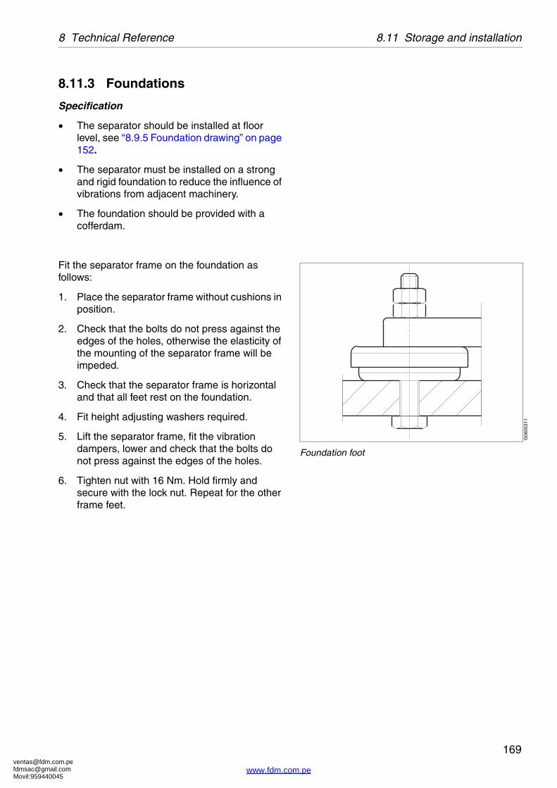
[email protected]@gmail.comMovil:959440045
169
8 Technical Reference 8.11 Storage and installation
8.11.3 Foundations
Specification
� The separator should be installed at floor level, see ‘‘8.9.5 Foundation drawing” on page 152.
� The separator must be installed on a strong and rigid foundation to reduce the influence of vibrations from adjacent machinery.
� The foundation should be provided with a cofferdam.
Fit the separator frame on the foundation as follows:
1. Place the separator frame without cushions in position.
2. Check that the bolts do not press against the edges of the holes, otherwise the elasticity of the mounting of the separator frame will be impeded.
3. Check that the separator frame is horizontal and that all feet rest on the foundation.
4. Fit height adjusting washers required.
5. Lift the separator frame, fit the vibration dampers, lower and check that the bolts do not press against the edges of the holes.
6. Tighten nut with 16 Nm. Hold firmly and secure with the lock nut. Repeat for the other frame feet.
G06
0531
1
Foundation foot
www.fdm.com.pe

[email protected]@gmail.comMovil:959440045
8.11 Storage and installation 8 Technical Reference
170
www.fdm.com.pe

[email protected]@gmail.comMovil:959440045
171
Reader’s Comment Form
Dear reader,
It is our ambition to produce as useful and instructive manuals as possible. Should you have any comments (positive or negative) regarding this manual, please note them down and send them to us. You can do this by copying this page and sending it by fax, or you could mail it, or hand it over to your local Alfa Laval representative.
Alfa Laval Tumba AB, Separator Manuals, dept. PPDM, SE-147 80 Tumba, Sweden. �Fax: +46 8 530 310 40.
Your name: Company:
Address: City:
Country:
Product: TX 612S-31CH Book No.: 1270342-02 Rev. 3
Date:
Yes No
Is it easy to find what you are looking for by using the table of contents? ❒ ❒
Are the chapter and section headings clear and adequate? ❒ ❒
Is the information presented in the correct order for your purposes? ❒ ❒
Does the information in the manual cover your needs? ❒ ❒
Is it easy to understand the instructions in the manual? ❒ ❒
Is the terminology sufficiently explained? ❒ ❒
Are the illustrations easy to understand? ❒ ❒
Your comments:�������������
www.fdm.com.pe

[email protected]@gmail.comMovil:959440045
173
Order Form
If you wish to order extra copies of this manual, please copy this page and give it to your local Alfa Laval representative, who will advise you of current prices.
Your local Alfa Laval representative will also be able to help you with information regarding any other manuals.
Your name: Company:
Address: City:
Country:
Product: TX 612S-31CH Book No.: 1270342-02 Rev. 3
Quantity: Date:
Comments:
��������������������
www.fdm.com.pe
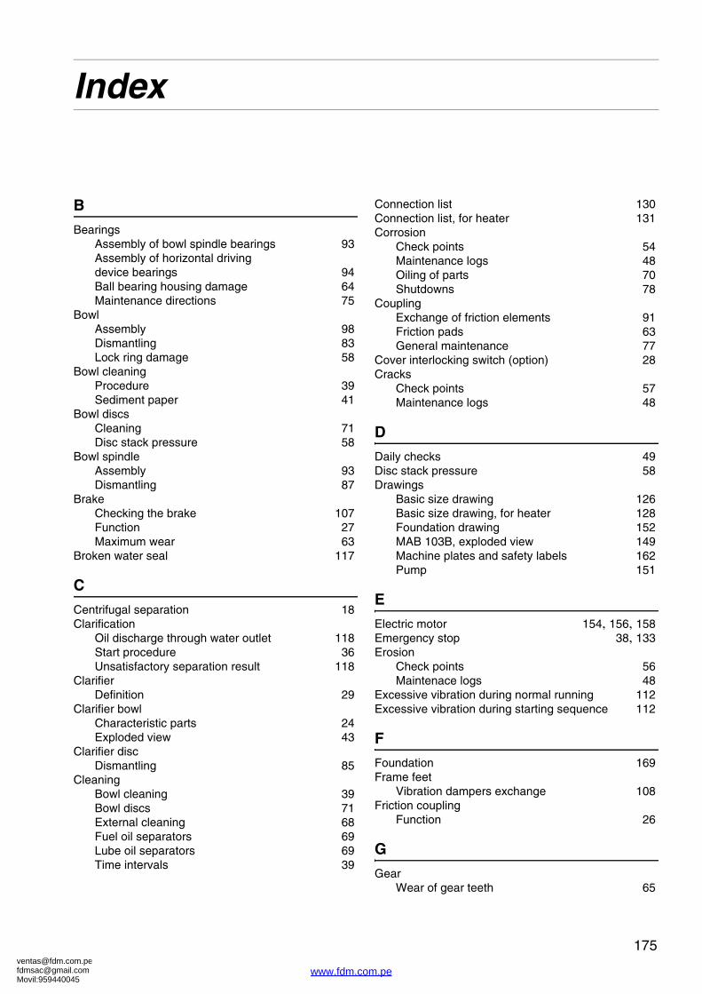
[email protected]@gmail.comMovil:959440045
175
Index
B
BearingsAssembly of bowl spindle bearings 93Assembly of horizontal driving�device bearings 94Ball bearing housing damage 64Maintenance directions 75
BowlAssembly 98Dismantling 83Lock ring damage 58
Bowl cleaningProcedure 39Sediment paper 41
Bowl discsCleaning 71Disc stack pressure 58
Bowl spindleAssembly 93Dismantling 87
BrakeChecking the brake 107Function 27Maximum wear 63
Broken water seal 117
C
Centrifugal separation 18Clarification
Oil discharge through water outlet 118Start procedure 36Unsatisfactory separation result 118
ClarifierDefinition 29
Clarifier bowlCharacteristic parts 24Exploded view 43
Clarifier discDismantling 85
CleaningBowl cleaning 39Bowl discs 71External cleaning 68Fuel oil separators 69Lube oil separators 69Time intervals 39
Connection list 130Connection list, for heater 131Corrosion
Check points 54Maintenance logs 48Oiling of parts 70Shutdowns 78
CouplingExchange of friction elements 91Friction pads 63General maintenance 77
Cover interlocking switch (option) 28Cracks
Check points 57Maintenance logs 48
D
Daily checks 49Disc stack pressure 58Drawings
Basic size drawing 126Basic size drawing, for heater 128Foundation drawing 152MAB 103B, exploded view 149Machine plates and safety labels 162Pump 151
E
Electric motor 154, 156, 158Emergency stop 38, 133Erosion
Check points 56Maintenace logs 48
Excessive vibration during normal running 112Excessive vibration during starting sequence 112
F
Foundation 169Frame feet
Vibration dampers exchange 108Friction coupling
Function 26
G
GearWear of gear teeth 65
www.fdm.com.pe

[email protected]@gmail.comMovil:959440045
176
Gravity discDismantling 85Selection 32
H
Horizontal driving deviceAssembly 94Dismantling 91
I
InstallationCheckpoints 32Planning of installation 166
InterfaceDefinition 29
Interface description 132
L
Lifting instruction 79, 153Liquid flows through bowl casing drain 115Lock ring
Wear and damage 58Lubricants 135Lubrication
Oil change procedure 72Oil filling procedure 106
M
Main parts 21Maintenance
Maintenance intervals 46Maintenance procedure 47Service kits 48
Major service 51Metal surfaces
Corrosion 54Cracks 57Erosion 56Gear teeth wear 65
MotorCoupling disc 62Motor cleaning 68
Motor current during start 35
O
OilBefore first start 32Oil change intervals 46Oil change procedure 72Sight glass 28
Oil discharge through water outlet 117Outgoing water contaminated by oil 116
P
Power transmissionDescription 26
PumpAxial play 102Bushings 101Dismantling 101Function 27Impeller shaft 101Lipring seals 101Shear pin coupling 101Wearing seals 101
PumpsCheckpoints 101
PurificationBroken water seal 117Definition 29Outgoing water contaminated by oil 116Start procedure 36Unsatisfactory separation result 116
Purifier bowlCharacteristic parts 22Exploded view 42Gravity disc 22
R
Revolution counterFunction 28
RotorAssembly 98Dismantling 83
Running-up procedure 34
S
Safety Instructions 9Separated sludge
Cleaning the bowl 39Separation
Clarification 24Optimum separation 23Purification 22Temperature 19Viscosity 19
Separator does not start. 110Separator exploded view 25Service kits 48Shear pin coupling 102Smell 113Speed too low 114Start 34
Checkpoints 33
www.fdm.com.pe

[email protected]@gmail.comMovil:959440045
177
Clarification start procedure 36Purification start procedure 36
Starting power too high 111Starting power too low 111Start-up time too long 110Stopping procedure 37Stopping time too long 114Storage 164
T
ThroughputDefinition 29
Trouble tracing 110
U
Unsatisfactory separation result 116
V
Vertical driving deviceAssembly 93Dismantling 87
VibrationCritical speed 34Spindle wobble 60Vibration checking 74
W
Warning signs 14Water in oil sump 114Worm gear
Function 26Worm wheel
Assembly 95
www.fdm.com.pe


![ZZZ ]LDUDDW FRP - ziyaraat.netziyaraat.net/booksTareekh/MolaAliMadinayMayPacheesSaal.pdf · 3uhvhqwhge\zzz ]lduddw frp. 3uhvhqwhge\zzz ]lduddw frp. 3uhvhqwhge\zzz ]lduddw frp](https://img.dokumen.tips/doc/110x75/5e045b61dc086d0f1330bd6d/zzz-lduddw-frp-3uhvhqwhgezzz-lduddw-frp-3uhvhqwhgezzz-lduddw-frp-3uhvhqwhgezzz.jpg)