Embed Size (px)
Citation preview
7'7 ADA1I9 506 NAVAL FACILITIES ENINEERNG COMN ALEXANDAIA VA F/O 13/110MARINE RAILWAYS. DESIGN MANUAL 25. .1 U)
UNCLASSIFIED NAVFAC-O-29. NLmmhhhhhhhhhlllllll
hhhhhhhhhhIIhilIIIIIIIIIflfllflfflfllflf IEN
..... UNCLASSI FIED
$CCU~t':ASC~O Orrj wi PG st-,l,,,SNREAD ISRCINREPORt DOCUMENTATION PAGE BEFORE COMPLETNG FORM1I. REPORT NUMBER 2. GOVT ACSINN ECIPIENT'S CATALOG NUMBE[R
4. TITLE (nd Subtitle) S. TYPE OF REPORT a PERIOD COVEREI
NAVFAC Design Manual DM-29.1, Design CriteriaMarine Railways Final
G. PERFORMING ORGQ, REPORT NUMBER
. AUOR) .- . DM-29. ONTRACT OR GRANT NUMER()
Naval Facilities Engineering Command200 Stovall StreetAlexandria, VA 22332
9. PERFORMING ORGANIZATION NAME AND ADDRESS 10. PROGRAM ELEMENT. PROJECT. TASKNaval Facilities Engineering Command AREA & WORK UNIT NUMBERS
200 Stovall Street Engineering and DesignAlexandria, VA 22332
114 11. CONTROLLING OFFICE NAME AND ADDRESS 12. REPORT DATENaval Facilities Engineering Command (Code 0432) January 1982200 Stovall Street 1. NUMBER OF PAGES
Alexandria, VA 22332 5014. MONITORING AGENCY NAME & ADDRESS(II dillrent frim Controllling Office) IS. SECURITY CLASS. (of thie report)
UNCLASSIFIED
ISa. DECL ASSI FIC ATION/ DOWNGRADINGSCHEDULE
I. DISTRIBUTION STATEMENT (o0 this Report)
Unclassif ied/Unlimited
- -i-r zp ved
I?. DISTRISUTION ST' TEMENT (of the abafracl entered In Block 30. II differmt from Repo") .
Unclassified/Unlimited
IS. SUPPLEMENTA Y NOTES
LW. KEY WORDS (Coinu.,e on revere aside if necesary aid idently by blot nmb.r)
Comparison with drydocks; controls; cradles; design loads; groundways;hauling systems; site selection.
Cl-
I to. STRACI (Continue on rers.. .side *ace,,, and Identify by block number)
__.j "Design criteria and construction information for use by qualified engineers areLA- presented for marine railways, Category'Code 213-20. The contents include:
comparison with drydocks; site selection; dimensions; design loads, groundways,cradles; hauling systems, controls; and support facilities
DODD ,, .1473 EDITION o, I NOV 65 IS OBSOLETESErCUIlTY CLA SSIFICATION OF T-41S PAGE. (14aern Date F~nterd )

NAVFAC DM-29.2JANUARY 1982
NTOr APPROVED FOR PUBUC RELEASE
MARINE RAILWAYS
DESIGN MANUAL 29.2
I,
DEPARTMENT OF THE NAVY( NAVAL FACILITIES ENGINEERING COMMAND
200 STOVALL STREETALEXANDRIA, VA. 22332
82 09 23 02S

1I
DISTRZBUrTZON: ( copy each unless otherwise specified) jSNDL 2 FG3 (Cheltenham and East 7 FT6
1 23A1 (COMNAVFORAZORES only) Machias only) 2 FT13 (Less Hillington)I 24J1 2 106 (Wahiawa and Norfolk only) 4 FT183 27G I 1113 (Beaufort only) I FT19 (San Diego only)
2 39B 1 F116 (Bethesda only) 2 FT221 39C1 I PH8 (Cairo only) 1 FT27 (Idaho Falls only)2 39E 7 PH25 (Philadelphia, Portsmouth I PT28I 42A3 VA, Camp Lejeune, Oakland, 4 FT314 45B Newport, Great Lakes, and 1 FT371 49 Long Beach only) 1 FT552 SIA 1 FJ5 I FT643 51B1 I FKA6A I 17T73]3 5133 1 FKA6A2 I lT74A (MIT only)4 B2A (JCS, NSA, DLA, and DNA I FKA6A3A 4 FT74B (California, Illinois,
only) I FKA6A3B Rensselaer, Georgia TechI B5 (USOC only) I FKA6A9 only)I C34 (Holy Loch only) I FKA6A12 1 FT78 (2 copies) i2 E3A I PKA6A15 (Code 321) 1 V2
6 FA6 (Bermuda, Brunswick, Cecil 1 FKA6A16 2 V3Field, Key West, I FKA9 9 V5Jacksonville, Virginia I FRM8 2 V8Beach only) 6 FP1/9 1 V12
6 FA7 (Guantanamo, Keflavik, I Y1M12 1 V14Brooklyn, Panama Canal, 1 F1013 6 VI5Mayport, Roosevelt Roads I M015 (Philadelphia only) 3 V16 (less Camp Smith)only) 200 PP.NI (West and Lent only, 100 2 V1? 7
I FAIO copies each) 2 V23I FAI8 150 FKNI (South and North only, 75 1 V254 F&23 (Antigua, Brawdy, Buxton, copies each)
Lewes only) O0 FKN1 (Pac and Ches only, 505 FA32 copies each) Copy to: (One copy each unless4 FB6 1 FKNI (Ches, FPO-I only) otherwise indicated)
7 FB7 (Alameda, Fallon, Lemoore, 2 FKN2 (less Pt. Hueneme)Oak Harbor, Miramar, North 13 11012 (Pt. Hueneme only, 13Island, Noffet Field only) copies) 3 21A 2
2 FBIO (Adak, Midway only) 36 P1N3 (6 copies each) I AZA (OUR only)I F313 (Bremerton only) 45 FKN5 (5 copies each) 1 A31 FB21 1 FKN7 1 A4AI FB31 (Guam only) I 1(N8 2 A52 F334 (Kadena, Sasebo only) I FKNIO 1 A6 (Code LFF) I4 FB36 (Big Sur, Coos Head, 1 P1NJI 2 C7 (Brazil and Chile only)
Ferndale, and Pacific 4 FIPIB (less Concord) 1 DIBeach only) 3 FKPIB (Concord only, 3 copies) I PE1
6 FB41 1 FKPIE I FGI1 738 3 FRPIj I PKAIA
I FC3 (London only) 1 FKPIH 2 FIAIB (2 copies)
2 FC5 4 FKP3A 50 FRAIC (Code 043 - 50 copies)I FC7 8 FKP7 1 FKAIFI FCl2 16 FKP8 1 FKN2 (Port Hueneme (Code 156)1 FC14 2 FKPIl only)I FD2 5 FKQ3 I FRI1 F2 2 FKRIA8 FE4 (Adak, Edzell, Hansa, 2 FPRIA (2 copies) Additional copies are available
Galeta Island, Homestead, I FKR2A (Dallas only) from: Winter Harbor, Sabana I FKE3ASecs, and Sonoma only) I FR3 Comanding Officer
1 F7 I 1 FKB Naval Publications andI F75 1 71(5 Forms Center1 F76 3 FlP.17 (3 copies) 5801 Tabor Avenue I2 F719 (New Orleans, Seattle only) 6 FR3 Philadelphia, PA 19120
1 FT38 2 FR46 FG2 (Balboa, Harold Holt, Nea I Fri
4akri, Thurso, Stockton, I 7T2and Ponce only)1 I
DII
IABSTRACT
Design criteria and construction information for use by qualified engi-
neers are presented for marine railways, Category Code 213-20. The contentsinclude: comparison with drydocks; site selection; dimensions; design loads,groundways, cradles; hauling systems, controls; and support facilities.
I
I ~
I
I
COpyE
29.2-iii!

FOREWORD
This design manual is one of a series developed from an evaluation of facili-ties in the shore establishment, from surveys of the availability of newmaterials and construction methods, and from selection of the best design
i practices of the Naval Facilities Engineering Coimand, other Government agen-cies, and the private sector. This manual uses, to the maximum extent feasi-ble, national professional society, association, and institute standards inaccordance with NAVFACENGCOM policy. Deviations from these criteria shouldnot be made without prior approval of NAVFACENGCOM Headquarters (Code 04).
Design cannot remain static any more than can the naval functions it serves orI the technologies it uses. Accordingly, recommendationa for improvement areencouraged from within the Navy and from the private sector and should be fur-vished to NAVFACENGCOM Headquarters (Code 04). As the design manuals are
i revised, they are being restructured. A chapter or a combination of chapterswill be issued as a separate design manual for ready reference to specificcriteria.
' This publication is certified as an official publication of the Naval Facili-Lies Engineering Command and has been reviewed and approved in accordance withthe SECNAVINST 5600.16.
I
CommanderI Naval Fac~lities Engineering Coimand
I!III
I
29.•2-vI

11
DRYDOCKING FACILITIES DESIGN MANUALS
Superseded chapters
DM Number in Basic DM-29 Title
29.1 1 through 9 Graving Drydocks
29.2 10 Marine Railways I29.3 11 Drydocking Facilities
Characteristics
4
-~I
I29.2-vi
i i l I I I - -i ..... . .. ..... .... ...l lT'-- - -- -
CONTENTS
~Page
Section 1. BASIC DATA ....... ............................ 29.2-1
1. SCOPE ......................... 29.2-1
2. BACKGROUND OF U.S. NAVY MARINE RAILWAYS . ........ . 29.2-1
3. PRINCIPLE OF OPERATION ................. 29.2-1
4. DATA ON MARINE RAILWAYS ..... ................ . 29.2-1
5. CANCELLATION ......... ...................... . 29.2-1
Section 2. TYPES .......... ........................ . 29.2-1
1. DESCRIPTION ...................... 29.2-1
2. ENDHAUL ......... ........................ . 29.2-1
3. SIDEHAUL ......... ........................ . 29.2-2
bection 3. COMPARISON WITH DRYDOCKS ..... ................ . 29.2-2
1. SPEED AND ECONOMY ...... ................... . 29.2-2
2. ADAPTABILITY ......... ...................... . 29.2-2a. Marine Railways ...... .................. . 29.2-2b. Graving Docks ...... ................... . 29.2-2
3. VESSEL OVERHAUL ....... .................... . 29.2-3a. Marine Railways ...... .................. . 29.2-3b. Graving Docks ....... ................... . 29.2-3
1 4. COSTS ............. ............... 29.2-3
a. Construction ....... .................... . 29.2-3b. Operation ........ ..................... . 29.2-3c. Maintenance ....... .................... ... 29.2-3
5. TIME REQUIRED FOR DOCKING AND UNDOCKING .......... .. 29.2-3
a. Comparative Time Requirement .... ............ .... 29.2-3
6. CLIMATIC AND HYDROGRAPHIC INTERFERENCES .......... .. 29.2-3a. Marine Railways ...... .................. .. 29.2-4b. Graving Docks ....... ................... ... 29.2-4
7. RELIABILITY ........ ... ...................... 29.2-4a. Marine Railways ..................... ... 29.2-4b. Graving Drydocks ...... .................. .. 29.2-5
29°2-vii
CONTENTS
Section 4. SITE SELECTION .. ..... ................ 29.2-5
1. REQUIREMENTS .. ....... ............... 29.2-5
2. SPECIAL CONSIDERATIONS .. .......... ....... 29.2-5a. Distance to the Channel. ....... ....... 29.2-5b. Inshore Area .. ...... .............. 29.2-5c. Hydrographic Conditions. ........ ...... 29.2-5d. Foundations. ....... .............. 29.2-5e. Favorable Climatic and Tidal Conditions .. ..... 29.2-5f. Mlooring Facilities .. ...... .......... 29.2-6
Section 5. PRINCIPAL DIMENSIONS .. ........ ......... 29.2-6
1. CHARACTERISTICS OF VESSELS .. ...... ........ 29.2-6
2. VERTICAL RISE OF CRADLE. ........ ........ 29.2-6a. Minimum .. ............. ........ 29.2-6
3. TRACK SLOPES .. ....... ............... 29.2-6
4. LENGTH OF TRACK. ...... ............... 29.2-6a. With Wheels.:................................29.2-6b. With Roller Trains ....... ... ....... 29.2-6
5. TOTAL LENGTH. .. .............. ...... 29.2-6
6. CRADLE DIMENSIONS. ....... ............. 29.2-7
7. HOIST HOUSE .. ............... ...... 29.2-7
Section 6. DESIGN LOADS. .. .............. ...... 29.2-7
1. REQUIREMENTS .. ....... ............... 29.2-7a. Load Distribution. ................. 29.2-7b. Alternate Method of Load Distribution.........29.2-8
2. COMPOSITE LOAD CURVE .. ...... ............ 29.2-8
3. ERRONEOUS LOAD CURVE ASSUMPTIONS. .. ........... 29.2-8a. Previous Designs .. ...... ............ 29.2-8b. Commercial Designs .. ....... ......... 29.2-8
4. POPPET LOAD .. ............. ........ 29.2-8
5. WIND LOAD .. .............. ........ 29.2-8a. Overturning Forces .. ...... .......... 29.2-8b. Stability. ....... ............... 29.2-10f
29 .2-vii
CONTENTS
Page
6. SEISMIC DESIGN LOAD. ................... 29.2-10
I Section 7. CHARACTERISTICS AND CLEARANCES. .............. 29.2-10
1. VESSEL CHARACTERISTICS .. ................. 29.2-10Ia. Application........................29.2-11
2. CRADLE CLEARANCES. .................... 29.2-11a. Keel Block Clearances. ................ 29.2-11
I Section 8. TRACK OR GROUNDWAYS. ................... 29.2-11
1. DETERMINATION OF DESIGN LOADS. .............. 29.2-11a. Inshore Position .. .................. 29.2-12Ib. Offshore Position. .................. 29.2-12c. Poppet Load........................29.2-12
2. ELEVATIONS AT OFFSHORE END ................ 29.2-12Ia. Optimum Design .. ................... 29.2-12b. Overrunning Cradle .. ................. 29.2-12(c. Vertical Curve .. ................... 29.2-12
3. TRACK SUPPORT.......................29.2-12a. Piles.................... ...... 29.2-13j ~b. Track Stringers.............. ...... 29.2-13
4. NUMBER OF RAILS........................29.2-13
5. CHAIN PATHS AND GUIDES .. ................. 29.2-13
6. CRADLE SUPPORT ......................... 29.2-13a. Roller System. ...................... 29.2-13b. Wheel System .. .................... 29.2-14
7. ROLLERS .......................... 29.2-14Ia. Roller Train Length. ................. 29.2-14b. Spacing........................29.2-14c. Material and Design. ................. 29.2-14
d. Frames. ........................ 29.2-14
8. WHEELS. .. ......................... 29.2-14a. Wheel Spacing. .................................... 29.2-14b. Wheel Bearings .. ..................... 29.2-21
c.Axles ......................... 29.2-21
29 .2-ux
CONTENTS
Page
Section 9. CRADLES ......... ........................ 29.2-21
1. MATERIAL ......... ........................ . 29.2-21 I
2. SHIP AND WIND LOADS ....... .................. 29.2-21
3. CHAIN PULLS ........ ...................... 29.2-21
4. KEEL AND BILGE BLOCKS ...... ................. . 29.2-21a. Spacing ......... ...................... 29.2-22b. Loads ........ ....................... . 29.2-22c. Special Cases ....... ................... 29.2-22d. Special Considerations ..... ............... . 29.2-23
5. SPECIAL FRAMING OF OFFSHORE END .... ............ 29.2-23
6. WALKWAYS ......... ........................ . 29.2-23
7. WALKWAY UPRIGHTS ........ .................... . 29.2-23
8. CRADLE TRUSSES ........ ..................... . 29.2-23a. Top Chord ....... ..................... . 29.2-23b. Bottom Chord ........ .................... . 29.2-23
9. CRADLE FLOORS ........ ..................... 29.2-24
10. LADDERS ........ ....................... .. 29.2-24
11. BOOTJACK ......... ........................ . 29.2-24
12. DRAFT GAGES ......... ...................... 29.2-24
13. FENDERS ......... ........................ 29.2-24
14. ANCHORS ......... ........................ 29.2-24
15. DOCKING WINCHES ........ .................... 29.2-24
Section 10. HAULING SYSTEMS ........ .................... 29.2-24
1. CHAIN REQUIREMENTS .......... ............... 29.2-24
2. HAULING GIRDER ........ ..................... . 29.2-24
3. INHAUL CHAINS ........ ..................... 29.2-24a. Working Strength ....... .................. . 29.2-26b. Number and Size of Chains .... ............. . 29.2-26
4. OUTHAUL CHAINS ........ ..................... . 29.2-26
29.2-x I
CONTENTS
4. Page
5. OUTHAUL SHEAVES ....... .................... . 29.2-26
6. HOIST ......... ......................... . 29.2-27a. Lubrication ....... .................... . 29.2-28b. Efficiency ........ ..................... . 29.2-28c. Special Precautions ..... ................ . 29.2-28
7. HOIST FOUNDATION ........ .................... . 29.2-28a. Rock Support ........ .................... . 29.2-28b. Pile Support ...... ................... 29.2-28c. Stresses .... ..................... 29.2-28d. Cracking ..... ................... . 29.2-28
8. MOTOR ....... ....................... .29.2-28
Section 11. CONTROL EQUIPMENT ....... ................... . 29.2-29
I 1. REQUIREMENTS ......... ...................... . 29.2-29
2. LINE PROTECTIVE EQUIPMENT .... ............... . 29.2-29
3. PRIMARY CONTROL EQUIPMENT .... ............... . 29.2-29
4. SECONDARY CONTROL EQUIPMENT.............. 29.2-29
5. SECONDARY RESISTORS ...... .................. . 29.2-29
I 6. MASTER CONTROL SWITCH ..... ................. . 29.2-30
g 7. EMERGENCY CONTROL ...... ................... . 29.2-30
8. OVERSPEED AND LIMIT SWITCHES .... .............. . 29.2-30
I 9. BRAKES ......................... 29.2-30
I Section 12. MACHINERY HOUSE ....... .................... . 29.2-30
1. REQUIREMENT ........ ...................... . 29.2-30
I Section 13. FACILITIES ........ ....................... . 29.2-31
1. TRACKS ......... ......................... . 29.2-31
2. DOLPHINS AND APPROACH PIERS .... .............. . 29.2-31
I 3. SANITATION ......... ....................... . 29.2-31
29.2-xi,I
CONTENTS
Page
4. SERVICES ......... ........................ . 29.2-31
a. Fresh Water ........ .................... 29.2-31
b. Salt Water Flushing and Fire Protection . ...... . 29.2-31 Ic. Steam ........ ....................... . 29.2-31d. Compressed Air ....... ................... . 29.2-31e. Electrical Power ....... .................. . 29.2-31
5. LIGHTING ......... ........................ . 29.2-31
Section 14. SIDEHAUL MARINE RAILWAY ..... ................ . 29.2-32
1. MULTIPLE CRADLES ........ .................... . 29.2-32
2. 3,000-TON FACILITY ....... ................... . 29.2-32
a. Design Load ........ .................... 29.2-32b. Synchronization ....... .................. 29.2-34
SECTION 15. DRAWINGS AND SPECIFICATIONS .... .............. . 29.2-35
1. REFERENCES ......... ....................... . 29.2-35
Glossary ............ ............................. Glossary-1
APPENDIX A: Metric Conversion Factors .... ................ . A-i
References ........... ........................... . Reference-i
FIGURES
Figure Title Page
1. Composite Weight Curves ....... ................... . 29.2-92. Live Loads on Marine Railway Cradles .... ............ 29.2-10
3. Live Load on Track ....... ..................... 29.2-11
4. Crane Track Layout, Submarine Base, New London, Conn .... 29.2-15
5. Foundation Layout, Marine Railway, Philadelphia
Naval Shipyard ......... ...................... 29.2-17
6. Typical Roller Nests ........ .................... 29.2-19
7. Typical Cradle Wheel ........ .................... 29.2-20
8. Stability Factors ....... ..................... 29.2-22
9. Detail of Boot Jack ........ .................... 29.2-25
10. Marine Railway Hauling Systems ..... ............... . 29.2-26
11. Chain Reeving Diagrams ....... ................... 29.2-27
12. Hoist Foundation ......... ...................... 29.2-29
13. Section Through Sidehaul Marine Railway ... .......... 29.2-32
14. Cradle Loads and Chain Pulls ...... ................ 29.2-33
15. Sidehaul Marine Railways ....... .................. 29.2-34
29.2-xii I

MARINE RAILWAYS
Section 1. BASIC DATA
1. SCOPE. This manual covers the design of marine railways for drydockingvessels to permit inspection, overhaul, and repair of all underwater portionsof the vessels. Section 3 compares marine railways and drydocks to show thedistinctive features of marine railways and to emphasize both their value andtheir limitations. Because each type has its special function, it is not
intended to imply that the various types of docking facilities are inter-jchangeable. A description of a sidehaul marine railway built for temporary
use of the Navy in World War II is given in Section 14. With that exception,all further statements regarding marine railways in this manual have referenceonly to the endhaul type.
2. BACKGROUND OF U.S. NAVY MARNE RAILWAYS. The first Navy marine railways,
with capacities of 2,000 tons for destroyers and submarines, were built atBoston, Massachusetts, and Charleston, South Carolina, in 1918. Two more, of2,500-ton capacity, were completed at San Diego, California, and Pearl Harbor,Hawaii, in 1920. The comparatively great length, displacement, and draft ofnaval vessels are the principal factors which have restricted the maximum sizeand capacity of Navy marine railways to that required for destroyers.
3. PRINCIPLE OF OPERATION. A marine railway, by utilizing the mechanicaladvantages of the inclined plane and geared hauling machinery, is able to pullthe cradle and vessel out of the water with a combination of horizontal andvertical movements.
4. DATA ON MARINE RAILWAYS. Data concerning all marine railways at navalshipyards and activities are presented in NAVFAC DM-29.3.
5. CANCELLATION. This manual, Marine Railways NAVFAC DM-29.2, cancels andsupersedes Chapter 10 of Drydocking Facilities, NAVFAC DM-29 of February 1974.
Section 2. TYPES
1. DESCRIPTION. Marine railways may be either the endhaul or sidehaul type.Both types consist of inclined groundways extending into the water, cradlesthat move on the groundway tracks, wheels attached to the cradles or rollertrains not attached to cradle or track, hoisting machinery, and chains orcables for hauling cradles out of or into the water.
2. ENDHAUL. All existing naval marine railways are of the endhaul type
because:
(1) Waterfront space is extremely valuable, and the principal advan-
tage of the endhaul type is that it requires only about one-third as muchfrontage as the sidehaul or broadside type.
(2) Operation is safer and less complicated.
(3) If a long, narrow, high vessel such as a destroyer is hauled bow
first with the pull exerted on a single drawhead on the centerline of the
29.2-1
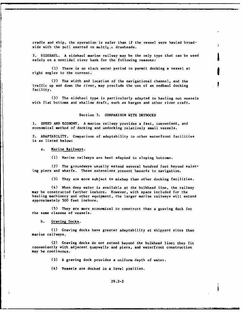
cradle and ship, the operation is safer than if the vessel were hauled broad-side with the pull exerted on multip.- drawheads.
3. SIDEHAUL. A sidehaul marine railway may be the only type that can be usedsafely on a nontidal river bank for the following reasons: I
(1) There is no slack water period to permit docking a vessel atright angles to the current. !
(2) The width and location of the navigational channel, and thetraffic up and down the river, may preclude the use of an endhaul docking Ffacility.
(3) The sidehaul type is particularly adapted to hauling out vesselswith flat bottoms and shallow draft, such as barges and other river craft.
Section 3. COMPARISON WITH DRYDOCKS
1. SPEED AND ECONOMY. A marine railway provides a fast, convenient, andeconomical method of docking and undocking relatively small vessels.
2. ADAPTABILITY. Comparison of adaptability to other waterfront facilitiesis as listed below:
a. Marine Railways.
(1) Marine railways are best adapted to sloping bottoms.
(2) The groundways usually extend several hundred feet beyond exist-ing piers and wharfs. These extensions present hazards to navigation.
(3) They are more subject to mishap than other docking facilities.
(4) When deep water is available at the bulkhead line, the railwaymay be constructed farther inshore. However, with space included for thehauling machinery and other equipment, the larger marine railways will extendapproximately 500 feet inshore.
(5) They are more economical to construct than a graving dock forthe same classes of vessels.
b. Graving Docks.
(1) Graving docks have greater adaptability at shipyard sites thanmarine railways.
(2) Graving docks do not extend beyond the bulkhead line; they fitconveniently with adjacent quaywalls and piers, and waterfront constructionmay be continuous.
(3) A graving dock provides a uniform depth of water.
(4) Vessels are docked in a level position.
29.2-2
I
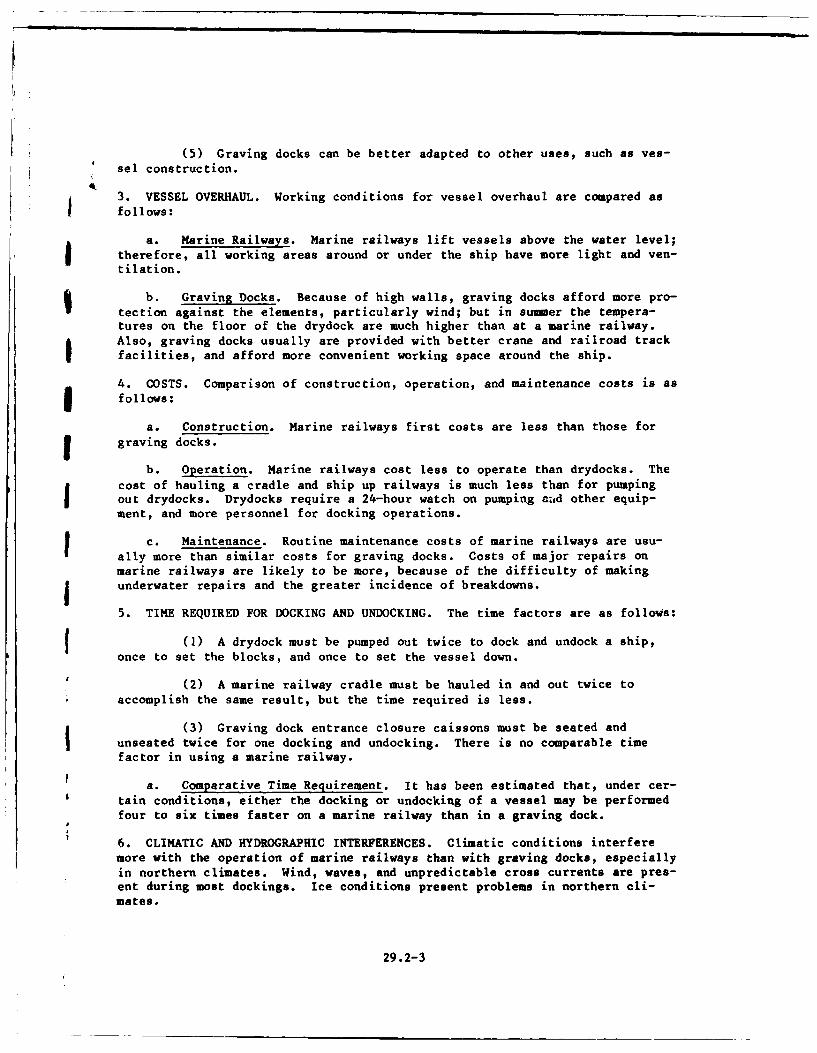
(5) Graving docks can be better adapted to other uses, such as yes-sel construction.
3. VESSEL OVERHAUL. Working conditions for vessel overhaul are compared asfollows:
a. Marine Railways. Marine railways lift vessels above the water level;
therefore, all working areas around or under the ship have more light and ven-tilation.
b. Graving Docks. Because of high walls, graving docks afford more pro-
tection against the elements, particularly wind; but in sumer the tempera-tures on the floor of the drydock are much higher than at a marine railway.Also, graving docks usually are provided with better crane and railroad trackfacilities, and afford more convenient working space around the ship.
4. COSTS. Comparison of construction, operation, and maintenance costs is asI follows:
a. Construction. Marine railways first costs are less than those forgraving docks.
b. Operation. Marine railways cost less to operate than drydocks. The
cost of hauling a cradle and ship up railways is much less than for pumpingout drydocks. Drydocks require a 24-hour watch on pumping ad other equip-ment, and more personnel for docking operations.
Maintenance. Routine maintenance costs of marine railways are usu-allycmore than similar costs for graving docks. Costs of major repairs onmarine railways are likely to be more, because of the difficulty of makingunderwater repairs and the greater incidence of breakdowns.
5. TIME REQUIRED FOR DOCKING AND UNDOCKING. The time factors are as follows:
oeo ) A drydock must be pumped out twice to dock and undock a ship,
once to set the blocks, and once to set the vessel down.
(2) A marine railway cradle must be hauled in and out twice toaccomplish the same result, but the time required is less.
(3) Graving dock entrance closure caissons must be seated andunseated twice for one docking and undocking. There is no comparable timefactor in using a marine railway.
a. Comparative Time Requirement. It has been estimated that, under cer-
tain conditions, either the docking or undocking of a vessel may be performedfour to six times faster on a marine railway than in a graving dock.
6. CLIMATIC AND HYDROGRAPHIC INTERFERENCES. Climatic conditions interferemore with the operation of marine railways than with graving docks, especiallyin northern climates. Wind, waves, and unpredictable cross currents are pres-ent during most dockings. Ice conditions present problems in northern cli-mates.
29.2-3
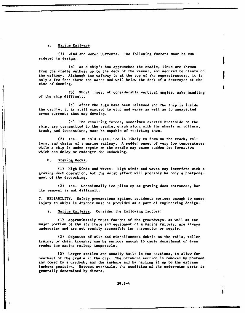
a. Marine Railways.
(1) Wind and Water Currents. The following factors must be con-sidered in design:
(a) As a ship's bow approaches the cradle, lines are thrownfrom the cradle walkway up to the deck of the vessel, and secured to cleats onthe walkway. Although the walkway is at the top of the superstructure, it isonly a few feet above the water and well below the deck of a destroyer at thetime of docking.
(b) Short lines, at considerable vertical angles, make handlingof the ship difficult.
(c) After the tugs have been released and the ship is insidethe cradle, it is still exposed to wind and waves as well as to unexpectedcross currents that may develop.
(d) The resulting forces, sometimes exerted broadside on theship, are transmitted to the cradle, which along with the wheels or rollers,track, and foundations, must be capable of resisting them.
(2) Ice. In cold areas, ice is likely to form on the track, rol-lers, and chains of a marine railway. A sudden onset of very low temperatureswhile a ship is under repair on the cradle may cause sudden ice formationwhich can delay or endanger the undocking.
b. Graving Docks.
(1) High Winds and Waves. High winds and waves may interfere with agraving dock operation, but the worst effect will probably be only a postpone-ment of the drydocking.
(2) Ice. Occasionally ice piles up at graving dock entrances, butits removal is not difficult.
7. RELIABILITY. Safety precautions against accidents serious enough to causeinjury to ships in drydock must be provided as a part of engineering design.
a. Marine Railways. Consider the following factors:
(1) Approximately three-fourths of the groundways, as well as themajor portion of the structure and equipment of a marine railway, are alwaysunderwater and are not readily accessible for inspection or repair.
(2) Deposits of silt and miscellaneous debris on the rails, rollertrains, or chain troughs, can be serious enough to cause derailment or evenrender the marine railway inoperable.
(3) Larger cradles are usually built in two sections, to allow foroverhaul of the cradle in the dry. The offshore section is removed by pontoonand towed to a drydock, and the inshore end by hauling it up to the extremeinshore position. Between overhauls, the condition of the underwater parts isgenerally determined by divers.
29.2-4
e (4) Where rollers are used, all sections of the roller train aresuccessively removed at the offshore end, because they gradually creep down-grade. At this time the roller section may be inspected, repaired, and in-stalled at the inshore end, but it may take several years before this sectionagain reaches the offshore end.
(5) Downhaul sheaves and their anchorages, and the submerged por-
tions of the track and chain troughs, which support and aline the chains, can-not be inspected or repaired except by divers experienced in this type of work.
b. Graving Drydocks. Most parts of graving docks are accessible for
inspection and repair each dewatering, except for outboard faces of entranceclosure, flooding, and dewatering systems.I
Section 4. SITE SELECTION
1. REQUIREMENTS. Site selection for a marine railway may be a part of thebroader problem of selecting new shipyard or shore activity locations, or itmay be confined to a study of possible sites at or near an existing activity.For new activities, the general site requirements for marine railways are (1)sheltered harbor, (2) a channel adequate in depth and width, (3) suitable soilor rock foundation, (4) satisfactory tidal, current, silting, and climaticconditions, and (5) sufficient area and suitable sites for all proposed appur-tenant facilities.
2. SPECIAL CONSIDERATIONS. Sites chosen for marine railways should satisfycertain definite and unusual requirements that often make their adoptionimpracticable, unwise, or uneconomical. The requirements set forth in thefollowing paragraphs are extremely important.
a. Distance to the Channel. The distance from high waterline or bulk-head line to navigation channel must be adequate for construction of therailway offshore end; it must also provide a safe fairway for vessels ap-proaching and leaving the marine railway.
b. Inshore Area. The land space available, including shore frontage,must allow for construction of the above water portion of the groundways andthe hoist house. Necessary side and end clearances, spur tracks, roadways,cranes, and working areas also must be provided.
c. Hydrographic Conditions. To prevent excessive silting, natural bot-tom slopes along the railway offshore end should be lower than track grade,unless the location is completely free from alluvial deposits and littoraldrift.
d. Foundations. Soil strength must be sufticiently high in the ground-way area to make possible a foundation design that will preclude settlement.
e. Favorable Climatic and Tidal Conditions. Proposed locations shouldhave natural protection from strong winds and waves, to avoid unfavorable dry-docking conditions. The design must provide for all combinations of adverse
conditions.
29.2-5

f. Mooring Facilities. Piers or dolphins should be provided on thewindward side, or both sides, of marine railways if conditions allow, tofacilitate warping vessels into the cradle. I
Section 5. PRINCIPAL DIMENSIONS
1. CHARACTERISTICS OF VESSELS. The Naval Sea Systems Command (NAVSEA) fur-nishes docking data regarding naval vessels to be drydocked. Data include:drawings, weight curves, docking plans, length overall, length on keel, beam,draft fore and aft, docking displacement, location of center of buoyancy,location of center of gravity, and location of external projections. Therated capacity of a marine railway is the docking (displacement) in tons (of2,240 pounds) of the heaviest vessel to be docked.
2. VERTICAL RISE OF CRADLE. Marine railways are generally designed for dock-ing a ship at mean high water with the deck of the cradle entirely dry. Thefreeboard at low end of cradle deck should not be less than 1 foot when ininhauled position.
a. Minimum. In general, the vertical cradle rise which must be providedfor in the track design is the sum of vertical dimensions; that is, height ofkeel block above track with cradle in extreme offshore position, plus vesselclearance over the top of keel blocks at mean high water of at least 1 foot,plus draft at stern of vessels to be docked.
3. TRACK SLOPES. Large marine railways are generally built with track slopesof either 3/4 or 7/8 inch per foot. The height of the blocks at the high orinshore end of the cradle should be as low as feasible to preclude the neces-sity of high blocks at the offshore end. Reductions in height of the offshoreend keel blocks can be obtained by sloping the top of the keel blocks. Aslope of 1/8 inch per foot is generally used. (See Section 8 for discussionof vertical curves in tracks.)
4. LENGTH OF TRACK. The minimum length of track is as specified below.
a. With Wheels. For cradles with wheels, the minimum required length oftrack is the sum of two horizontal dimensions:
(1) Distance the cradle must travel to rise the determined verticalheight. This distance is equal to the vertical rise divided by the trackslope.
(2) Length of blocks on cradle.
b. With Roller Trains. For cradles designed to travel on independentroller trains, determine the minimum length of tracks for wheels and add thelength of two roller sections. This increase is necessary to permit occa-sional removal of one section at the offshore end and reinstalling it at theinshore end.
5. TOTAL LENGTH. The minimum total length of marine railway is the minimumtrack length plus the distance required for necessary clearances and hoist
229.2-6
I
house. The ideal length of railway includes tb minimum length plus an exten-sion of the track at inshore end of about 100 feet to permit hauling the cra-dle entirely out of the water for inspection and repair.
6. CRADLE DIMENSIONS. Determine the in-the-clear dimensions of the cradle bythe maximum overall length, beam, and draft of vessels to be docked. Obtainthe length to be provided on blocks from the NAVSEA docking plan for the long-est vessel. Use this distance to determine the necessary length of cradle onrollers or wheels. Provide adequate working space all around the vessel, byextending a deck beyond the vessel's perpendiculars about 15 feet at each endand clearance of about 5 feet on each side at vessel's maximum beam. Somesmall cradles, which can be hauled in over stationary platforms, do notrequire decks.
7. HOIST HOUSE. Provide a hoist house containing hauling machinery consist-ing of an electric motor, a train of reduction gears, and the wildcat or wirerope drum. For large (3,000 tons) marine railway, make the hoist house about29 feet wide by 42 feet long. A clear, paved space at least 30 feet wideshould be provided at the rear of the hoist house to permit wheeled trafficbetween the two sides of the railway.I
Section 6. DESIGN LOADS
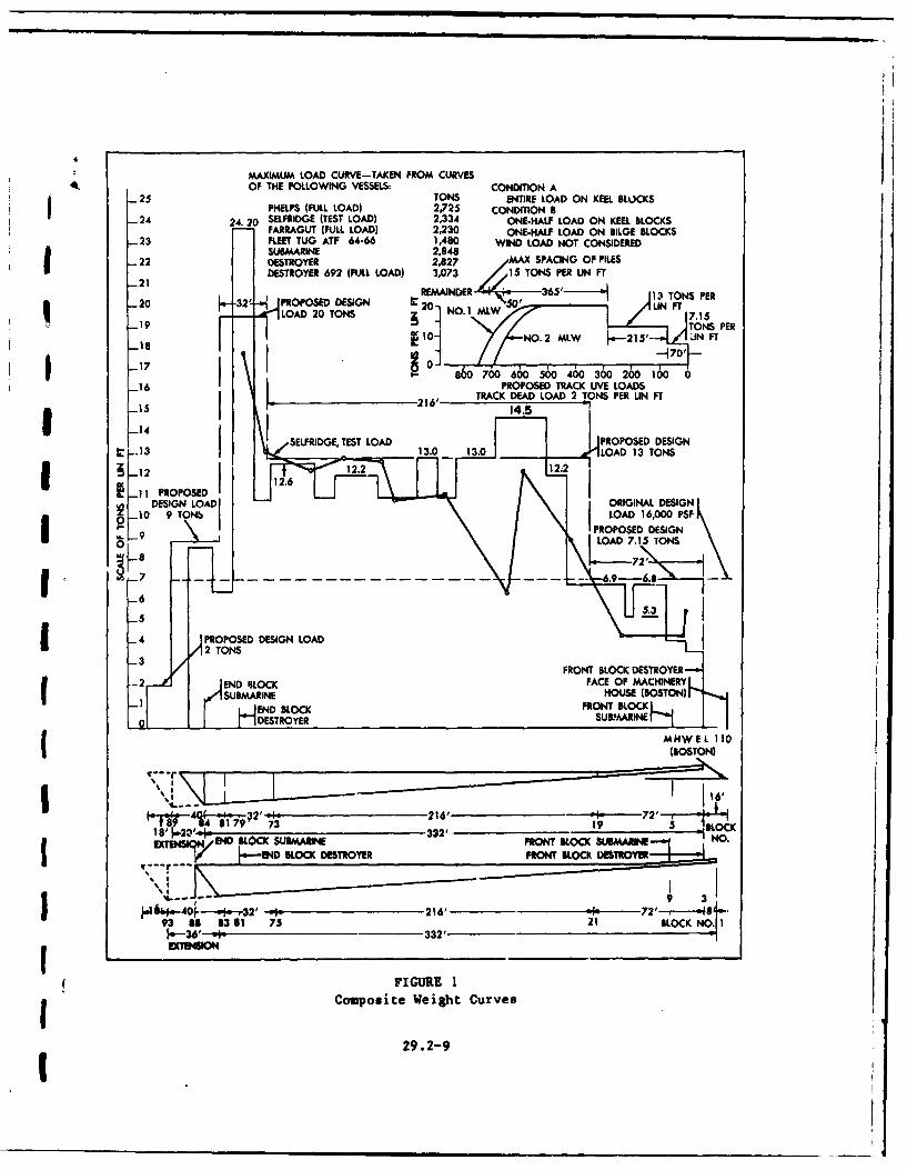
1. REQUIREMENTS. Vessels in docking condition are in a light operating con-dition, but an emergency may require docking a ship in full load condition.Design all marine railways for this condition. The size of the ship does notnecessarily establish the maximum load per lineal foot to be used for designpurposes. Fleet tugs may have much greater load concentrations than largerships of another class or type. Design groundways and cradle of a marinerailway for the maximum unit loadings as determined from composite weight dis-tribution curves of the various vessels that it will be required to haul.
a. Load Distribution. Consider the problem of load concentration fortwo ships as follows:
(1) Assume one ship has a displacement equal to the rated capacityof the marine railway, and its weight is uniformly distributed over the cradlelength.
(2) Assume a second ship has a displacement less than the railway
rated capacity, but its weight distribution curves show greater concentrationof weight than for the first ship. Under this condition the facility may notbe strong enough to support the second or smaller ship. Therefore, it will benecessary to obtain the weight distribution curves of all of the vessels to behauled.
(3) It is also necessary to consider all types of classes of ships,planned or under design, that may have to be hauled in the future.
(4) After these data are obtained, it is necessary to consider a
complete docking cycle with these ships on the cradle blocks.
29.2-7
(5) When a destroyer is seated on the cradle blocks, the stern endis unsupported for a considerable distance; this results in a concentration ofweight on the after blocks. This concentration is indicated on the weightdistribution curve, and it is necessary to make proper allowance for thisredistribution of weight in the design. This allowance may be made by assum-ing that the weight of the entire cantilevered portion is concentrated on thelast two or three blocks. This assumption generally results in a very heavyload per lineal foot, and may call for a crib and/or a grillage to be provided !at this point.
b. Alternate Method of Load Distribution. Compute the trapezoidal load-ing on the blocks resulting from the ship's weight curve center of gravitybeing eccentric to the center of gravity of the effective bearing area of thekeel blocks. This method is satisfactory when the cantilevered portion of theship is not large.
2. COMPOSITE LOAD CURVE. Prepare a composite weight distribution curve ofvessels under consideration. Express the ordinates of this curve in long tonsper lineal foot of vessel length. Having imposed all ship weight curves onone diagram, make allowance for overhang at the bow or stern ends. This com-posite weight distribution curve is then faired up for use as the design loadcurve for the cradle and groundway. Typical composite weight distributioncurves are shown in Figures 1 and 2.
3. ERRONEOUS LOAD CURVE ASSUMPTIONS. There are several possible sources oftrouble to be avoided in establishing a load curve for a marine railway.
a. Previous Designs. Weight distribution curves from previouslydesigned marine railways should be used with discretion. They will not pro-vide proper allowance for the characteristics of new ships, and any errors inthe load curves will be perpetuated.
b. Commercial Designs. Generally, there is no similarity between loadconcentrations encountered in a naval vessel and in a commercial vessel ofsimilar displacement. Therefore, load curves used in the design of commercialmarine railways are not used for the design of naval marine railways.
4. POPPET LOAD. Poppet loads occur under certain conditions during launchingor hauling when keel blocks are built on a slope. These loads may occur underother conditions and should always be considered. For a discussion and deter-mination of poppet loads, see Rossell and Chapman, Principles of Naval Archi-tecture, Volume 1, Chapter VII Launching.
5. WIND LOAD. Consider load on bilge blocks and stability as. follows:
a. Overturning Forces. When wind acts on the side of a docked vessel,the bilge blocks on the leeward side will be subjected to additional loadbecause of the overturning tendency. Determine the additional wind load byapplying the total wind pressure in pounds at the center of gravity of thetotal side presentment area of the vessel.
29.2-8
MAXIMUM LOAD CURVE-TAKEN FROM CURVESAOF THE FOLLOWING VESSELS: CONDITION A
-25 TONS ENTIRE LOAD ON KEEL BLOCKSPHELPS (FULL LOAD) 2,725 CONDITION B
-24 2.20 SELFRIDGE (TEST LOAD) 2,334 ONE-HALF LOAD ON KEEL BLOCKSFARRAGUT (FULL LOAD) 2,230 ONE-HALF LOAD ON BILGE BLOCKSF2 LEET TGATF 64-66 1,480 WIND LOAD NOT CONSIDERED
*SUBMARINE 2,848*22 DESTROYER 2,827 MAX SPACING OF PILES
-2 DESTROYER 692 (FULL LOAD) 3,073 15 TON PER LIN FT
REMAINDER 13 TONS PER20 _32'- PROPOSED DESIGN U0LN FT
LOAD 20 TONS z 7.15-19
I
-18 01--70i
I- 60700 600 500 400 300200100
-16 PROPOSED TRACK UIVE LOADSTRACK DEAD LOAD 2 TONS PER UIN FT
SELFRIDGE, TEST LOAD 1. 130PROPOSED DESIGN
11PROPOSED 1.
DESIGN LOADIOGNA G10 9 TONb LOAD 16,000 PSF
-1-9 \PROPOSED DESIGN
I -6
-5U .
- 4 APROPOSED DESIGN LOAD32 TONS
FRONT BLOCK DESTROYER-2END 4LOCNK FACE OF MACHINERY
SUBMARINE HUE(OTNEND BLOCK
I DESTROYER SUBMARINE
MNWEL 110
(BOSTON)
f 99 * 7 2 3 1918'
END4 BLOCK DESTROYER FOTBOKDRY
IIib&4-40rf-win ,.32' pi 216'72 i93 lB 6361 75 21 BLOCKNO
-- 36' m 0 - 332'
FIGURE 1Composite Weight Curves
29.2-9
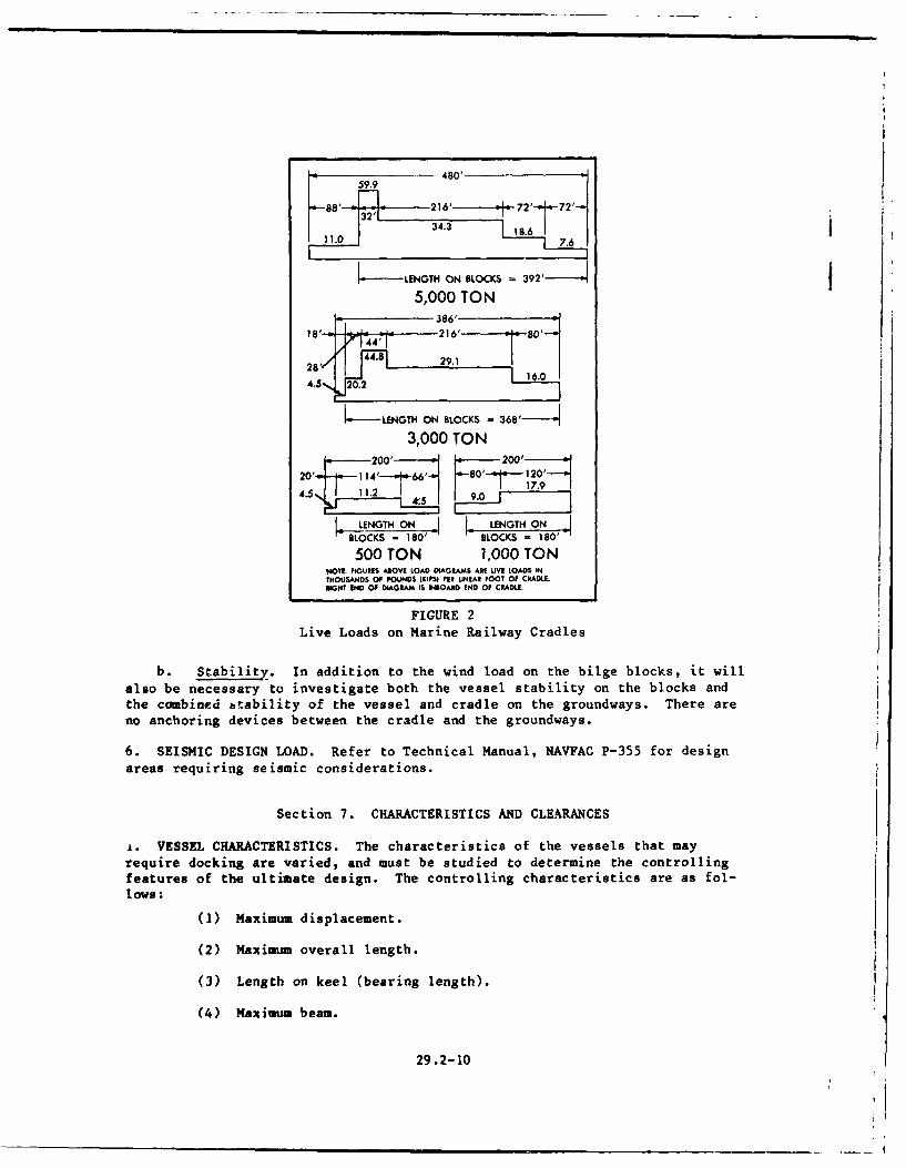
480'59.9 40
32'F-34.3 18. 6 I 7
_ LENGTH ON BLOCKS -392 '-4_5,000 TON
386'
18' 4' F - 216' 0'-
28'/ 4. 29.1
4.5., 20.2 16.0
.- _-LENGTH ON BLOCKS = 368 --- - -
3,000 TON~200'
4.5 " 1 1 .2 1,s I - 7.9
LENGTH ON LENGTH ONBLOCKS - 180' BLOCKS = 180'
500 TON 1,000 TONNOTE: FIGURES ABOVE LOAD DIAGRAMS ARE LIVE LOADS INTHOUSANDS OF POUNDS (KIPS) PER LINEAR FOOT OF CRADLFAEIGHT END OF DIAGRAM IS INIOARD END OF CRADLE.
FIGURE 2Live Loads on Marine Railway Cradles
b. Stability. In addition to the wind load on the bilge blocks, it will
also be necessary to investigate both the vessel stability on the blocks andthe combined btability of the vessel and cradle on the groundways. There are
no anchoring devices between the cradle and the groundways.
6. SEISMIC DESIGN LOAD. Refer to Technical Manual, NAVFAC P-355 for design
areas requiring seismic considerations.
Section 7. CHARACTERISTICS AND CLEARANCES
&. VESSEL CHARACTERISTICS. The characteristics of the vessels that mayrequire docking are varied, and must be studied to determine the controllingfeatures of the ultimate design. The controlling characteristics are as fol-lows:
(1) Maximum displacement.
(2) Maximum overall length.
(3) Length on keel (bearing length).
(4) Maximum beam.
29.2-10
(5) Maximum draft forward and aft in docking condition.
(6) Shape.
(7) Weight distribution.
3 (8) Appendages that may extend below the keel line and require spe-
cial treatment, including propellers, rudders, and sonar devices.
a. Application. From this hypothetical vessel, determine the length,b draft the blocks, and other characteristics of the cradleand ways plus the added working clearances required.
2. CRADLE CLEARANCES. It is necessary to add certain clearance dimensions tovessel dimensions to provide working space around and under the ship. Forspecific requirements, see Section 5.
a. Keel Block Clearances. The maximum keel block height is 4 feet. Theheight of the blocks forward, however, is generally established as stated inSection 5. A clearance of at least 1 foot should be provided between the keel
of the vessel of the deepest draft, and the top of the keel blocks at the in-shore end of the cradle at mean high water when the cradle is in extreme off-shore position on the groundways.
Section 8. TRACK OR GROUNDWAYS
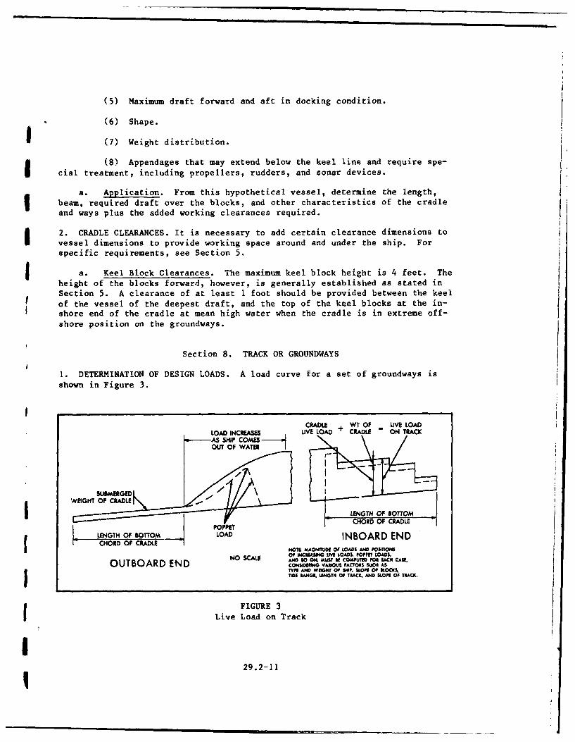
1. DETERMINATION OF DESIGN LOADS. A load curve for a set of groundways is
shown in Figure 3.
CRADLE WT OF UVE LOADLOAD INCREASES UVE LOAD + CRADLE - ON TRACK
OUT OF WATER I
SUAM I E r 100
LENGTH OF BOTTOMPOPPE CHORD OF CRADLE
LE4GTH OF BOTTOM LOAD INBOARD ENDCHORD OF CRADLE
NOT! MAGNIT"UDE OP LOADS AND POStflONSOF NCUAWO LIVE LOADS POPPET LOADS,
RNO SCALE AND 60 O O MSt , oMR EACH CAWE.OUTBOARD END , VARMS PACTONS SUCH ASTYP AND W ONT OF S0P, KOP OF KOC ,TIDE RANG, LISTH OF TRlAC AND SLOE OF TRACK.
FIGURE 3
Live Load on Track
229.2-11
Ii
a. Inshore Position. Consider the cradle in the inshore position wherethe groundways are supporting the live load on the cradle, as well as theweight of the cradle and the groundways themselves. As the cradle is hauledoffshore, the zone of maximum load per lineal foot on the cradle begins tomove offshore also, so that the groundway is subjected to the maximum load perlineal foot until the point is reached at which the effective weight of theship on the groundways begins to be reduced by buoyancy.
b. Offshore Position. Eventually, a point is reached at which the shipis entirely waterborne, and the only effective load on the ways is that of thecradle and the ways.
c. Poppet Load. The poppet load occurs somewhere between the twoextreme positions of the cradle, as noted previously in Section 6.
2. ELEVATIONS AT OFFSHORE END. Determine elevations at the offshore end fromthe following:
(l) Maximum drafts, forward and aft, of the design vessel.
(2) Slope of the track.
(3) Slope of blocks on the cradle.
(4) Length of the cradle.
(5) Height of upper block above track.
(6) Depth of water (including 1 foot clearance) over blocks at off-shore position of cradle.
a. Optimum Design. Although most marine railways are designed to allowfor docking at mean high water, the optimum design will provide for dockingthe design vessel at mean low water. This should be considered when practi-cable, especially when the tide range is low, and when other project require-ments permit.
b. Overrunning Cradle. When designing marine railways, do not assumethat in docking vessels it is possible to run the cradle down until its lowerend projects beyond the end of the track. This is not good practice because,when rollers are used, a section of the train may drop off the end of thetrack unless stops are provided. Construct cradles with a so-called fantailcantilevered projection at the outer end, thus increasing the effective lengthof the railway.
c. Vertical Curve. Although marine railways may be constructed with thetrack in the form of a vertical curve, this construction is not recommended.This arrangement permits shortening the track by increasing the slope of theoffshore end, but its disadvantage is that the slope of the keel blocks variesaccording to the position of the cradle. There is also greater difficulty inconstruction. I
3. TRACK SUPPORT. A practically unyielding track support is necessary toavoid excessive stresses resulting from misalinement or damage L track,
29.2-12 I
cradle, and vessel. Support groundways by piles or concrete slabs on rock orcoral, or a combination of both.
a. Piles. Piles may be timber, concrete, or steel. The maximum designload for pile foundations may be determined in the NAVFAC DM-7 series, or itmay be determined by foundation test piles. The groundway structural membersmay be concrete or timber. Provisions may be necessary for resisting lateralwind loads by the use of batter piles. Provide cross struts and horizontal
and vertical diagonal bracing as required by design conditions. Simplicity inthe design of underwater work is necessary.
b. Track Stringers. Do not place track stringers directly on pile heads
because the difficulty of driving piles in the exact positions required, andof cutting them off underwater to exact grades, makes work slow, costly, andof uncertain quality.
(1) Cross Capped Pile Bents. With pile bents cross capped, thealinement of the piles is of less importance, and stringers may readily bebrought to exact grade and full bearing by means of wedges.
(2) Two-Pile Bents. Where heavy loads are involved, two-pile bentsunder each rail may be necessary. In this case, every fourth or fifth capshould extend across the pile supports of both rails, and form part of thetrack bracing system.
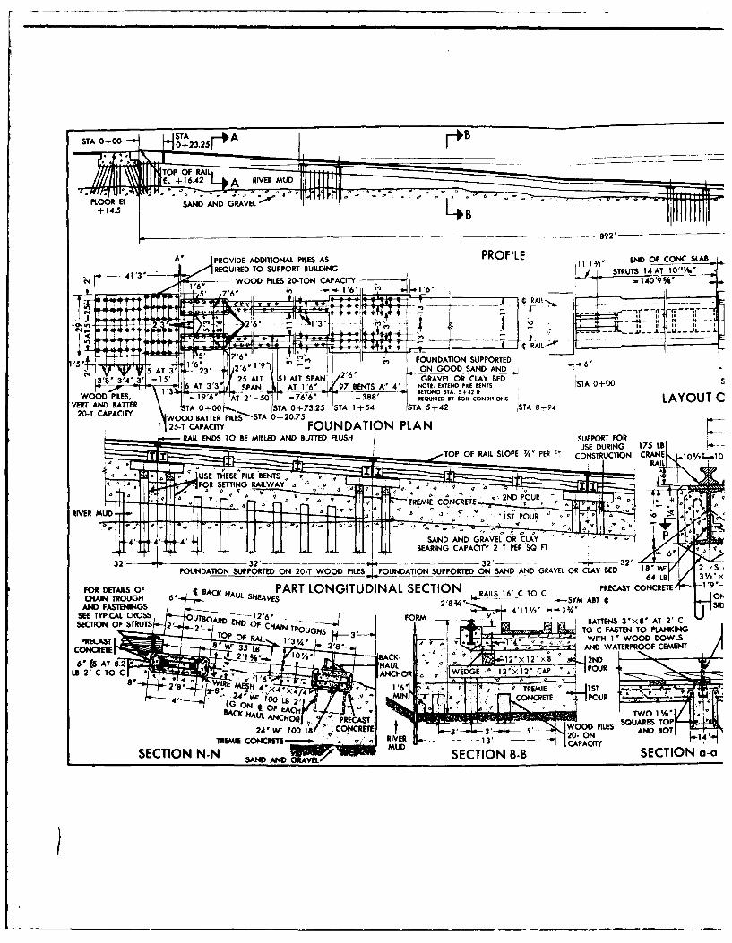
4. NUMBER OF RAILS. The number of rails may be two, three, or four. Navymarine railways usually have two rails. Three- and four-rail tracks have theadvantage of a continuous support under the center of the cradle and keel ofthe vessel. (See Figure 4 for typical crane track construction, and Figure 5for typical marine railway track construction.)
5. CHAIN PATHS AND GUIDES. Construct chain paths and guides between rails asindicated on the drawings in Figure 5. Make these chain paths of treated orgreenheart timber. Wear on the timber paths may result in the chains bearingon the holddown bolts, causing wear on the chains as well as the bolts. Ex-perimental work with chain paths assembled with hardwood dowels in place ofspikes and bolts indicates that such construction is satisfactory. Use a1/2-inch steel wearing plate attached with countersunk head screws to preventthe chain path from wearing out too frequently. Chain paths should be contin-uous and constructed to permit easy renewal. Provide separate chain paths forbackhaul chains.
6. CRADLE SUPPORT. There are two methods of supporting the cradle on thetrack: (1) by a system of rollers in contact with a continuous plate (uppertrack) on the bottom chord of the cradle and a second continuous plate (lowertrack) on the top of the groundways, or (2) by a system of wheels attached tothe cradle and rolling on a rail or heavy plate forming a part of the ground- iways.
a. Roller System. When rollers are used, rails should be of plate steelfastened to track stringers by countersunk drift bolts. When base plates areused under the rail plate, they should be of sufficient thickness to preventcurling up of the projecting sides, caused by compression of the timber underthe rail. Do not vary the rail plate thickness at different points.
29.2-13

b. Wheel System. When the cradle is equipped with wheels, use standardrailroad or crane rails of size adequate to support the wheel loads, and usebearing plates between the rails and stringers. Use 1/4-inch spaces betweenthe ends of adjoining rail lengths or use standard splice plates. Fastenrails securely to the track stringers, particularly at the rail ends.
7. ROLLERS. Assemble rollers in sections or nests, and hold in place byframes that are spliced together to form one continuous roller train. (SeeFigure 6 for assembly and details.)
a. Roller Train Length. The total length of a roller train is equal tothe length of the cradle, plus one-half the distance of extreme travel of thecradle, plus a minimum of one or two extra sections to allow for creep. Aserious disadvantage of rollers develops when the outer end of the rollertrain is running light or without cradle load. Under this condition, thepresence of silt, driftwood, or other obstruction on the rail may cause thederailment of the roller train.
b. Spacing. The size and spacing of all the rollers is determined fromthe maximum design track load per lineal foot on the ways. The rollers at theoffshore ends of the trains are not subjected to as much pressure as others.It is not advisable to vary the roller spacing, however, because the rollersslide slightly during operation and gradually creep down the ways; thisrequires periodic removal of the lowest roller sections, and their reinstalla-tion at the inshore end of the rolier train. In the course of time, everyroller section will occupy a position in which it will carry extreme load;therefore, all the rollers must be of one design and spaced the same distanceapart. Roller trains on the two tracks can creep at different rates.
c. Material and Design. Make rollers of cast steel by setting the steelspindle in the casting mold and pouring the molten steel in the mold, so thatwhen the steel hardens the spindle will be rigidly fixed in the roller. Ma-chine rollers harden after heat treatment. The physical characteristics ofthe roller material correspond to cast steel chain. Hold roller diameters toclose tolerances not exceeding 1/32 inch.
d. Frames. Hold roller sections at the required spacing by side angleframes. Weld steel pads to the angle frames, and drill holes of the propersize through the pads and angle to form the spindle bearings. See Figure 6for a typical welded plate splice detail of the roller frames or nests and themethod of pinning it together. Use cast iron spacers with through bolts tohold the frames together. Provide a cast iron plow at the offshore end of thetrain, to clear the track of obstructions such as silt or driftwood.
8. WHEELS. There is less danger of a derailment or serious accident with acradle mounted on wheels.
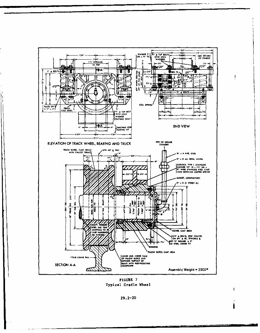
a. Wheel Spacing. Vary the spacing of wheels, the closest spacing beingwhere the heaviest concentration of load occurs, and the widest spacing wherethe load is least. There should be a few extra wheels at minimum spacingunder the inshore end of the cradle to take caie of the poppet load. Vary thespacing, but all wheels and axles should be designed alike. (See Figure 7.)
29.2-14

-ILE Al- ON
Ao INBOARD POSITI OF0
FAC OFWL CAL USING 10' CHAIN
1 ____ CONCRffTE MAT ON ROCK\
RAL
TRACKI ~~CAN - ______________
A4' EXISTING TRACKI
EXISTING TRACK TO BE(2RELOCTED T THIS(24" SQ PIERS)(2
POSITION BY THE YARD (16" SQ CONCRETE PILES) 8 SP AT 201 160'- 1-20" 20'-4121Y
PLANSCAE 20'
A1 1PPROX EX ISTING GRADETOOFC
10 11 12 13 14 1s 16
6 8 9 PROFILEAPPROX ROCK LINE 3 SCALE 1 =20'
2 ~ CRANE TRACK
TOP OF RAILS 9EL 101.5
MIW ELO0D
SECTION A-ASCALE V'

+ +++ + +
- 4--
liii ____
JOUTLINE OF CRADL PCKAINBOARD POSITIO OfITO
cRADLE USING I0 CHIN
(24"SQ PERS (5i*W CYMNDRS ROOCNE TOC AP XITN PIERALBEDN
____________THIS_ POSITION BY BYTHE YARD2---20W- 20' 0--20 +i0 THE YARD
PLAN +5 ti." + '-4SCALE V~=20' 4N4 4F12 -A
2' w A -[ r
TOP OF EXISTING
TOP OF CRANE TRACK SUPPORT EL 10 ~ ODPIER EL. 10.5
. .. .. .. . .. .. .. .. .. .. .M H W EL 2.5710 11 12 13 14 13 16 17ML E 0.0 44 44 44 44 44 44 4 44
10 II 1 1 4 S 6 17~19 20 21
PROF~ILES ISCALE I'=20'TRC
4 CRANE TRACK 0TOP OF RAILS 9. 11'6 I 5'6
MRINE RAILWAY- DESIGN ASSUMPTIONSEXISING TRUCUREGANTRY CRANE 30 TONS AT 40o
WHEEL LOADS IN 1 00 POUNDS.WHEEL LOADS DO NOT INCLUDE
MLW aBOO IMPACT OR WINO.
SECTION A-ASCALE 411- I'I
FIGURE 4Crane Track Layout, Submarine Base,
New London, Conn.
29.2-15
STA 0+00-L j SO+ 23.25 A +4
TOP OF RAILEL + 16.42 kA RIVER MUD
FLOOR El SAND AND GRAVELI ..-+14.5 B
-892'
6'* PROVIDE ADDITIONAL PILES AS 111FIL END OF--ONCSLABSTRUTS I IAT I10%'
= 40'9%WOOD~~-,-~ PIE 0-T-APCT
1'ONDTONSPPRED6
5A 0+006'
TOP OFRALILOE -';'-R~ CNTUTIN CAE ~ 1
SA6 n ONDAIND GUPRAVEDO LY 'aP
32 3T3 '' 2' -- 32) ONGO-SN NFOUN3AT315'ION SUPOT ON 20 WOOD PILES FOUNATIO SPORE NSN N RVLO CLAY BED 1
CSAHAIN6 7 ETSA 4RUG 6'TE EXAUL SHELVE BENTS S AT 0+00
SECTIONC OF STRUTS 2'ES ST 0+A2EN0.75 A 225-TT CAACT FASTATIN TOA PNNN
URAILD TO '6 BE MILLED;-: AND WArD LS SPO TERPOFCMN
'a'V 2ENH P OURT POU
~~~~~TREMIE CONCRETE'..~ .~ RIE N 0
SAN AND G4VL SECTIO ANaRVL-aCA '''r
I'UBAIGCPCT1 E 5 T6
c 0J=AT 2'C TO C RLS 16' C TO C a
TOP Of RAJE SLOPE V PER__ FT1 L+2 STB9 X
TPO RALEL 48.62,
Lm Ln 0 DETAIL Us 04J
ED OF RAIL STA 8+92 V)~ TO 14X I' PLATECONCSA TRACK ASSEMBLY FOR SUBMERGED CONIST __', 4- , _~cr,
1O~'21 PANELS AT 32'=672'r5%
RAIL -- C O
I ' 1 1
11 SMAT CAPTACIT16' CAI TO C RAIL 2'6
K-2' --- 4---- ------ -3232 323A
'V- BENTIS P, PLNKN TRAC
104'/2' 102 L14XI AR2X2 CADMIUM PLATED & _ .W=.5 S
fi ~ ~ ~ ~ ~ ~ ~ ~ ~ ~~ WR TAKWMEIESEHTHLTEDTI ,TAKWLE
WIREMESH4'X4X4/4WT=O853 SF SM AB 4 I4'COCRET
34-0 AT 24- C TO C BETWEEN STRUTS To8 s' A 35 L6' ' ~- -~--=.-~- -~----- .'-1~PRECAST PLAN T-T
2 1/ x 3/21x3'/21 x'A8' LG CONRET
3 'x9'A '/ CROSS SECTION OF TRACK ASSEMBLY FOR SUBMERGED 2o OFRAL 6X'6R qONE +I' SQUARE 3' EACH CONSTRUCTIO'.i 1 0 RAILS 16' C TO C TO OF RAIN I TF
, fALSTRUTS P4I41~4x'PLTSIDE~1 OF W FAL ~ 64 LB 1 /-
C 1. 0.
ING 1. 0 CAP SCREWS '/4"A1/LS WITH INSERT I10'1' X02/' d1'"ENT C TO CON THE SLOPE 1 x2 2
1/2 ''
'A A12X1'8 2N I 6'X4'
- - ~ POUR
S~4' W'0 TIE RODS 7iLa 6' B TO Si
1/2 ''0 AT 8' C To 4'.44 AjC4N C BOTHWAYS ALT '--' a
STR AND BEN4T NOTE: ADJUST FOR CORRECT AL04FAENT OF SUPPORT AS
%0 AT SEAMS HWOR POWING PRECAST CONCEIT! sAND --- 8'EDFO7' C TO CAMCNTUTOANHRFRRDL
ION a SECTION P-P GRAVEL SCINC-CANHRORC DL
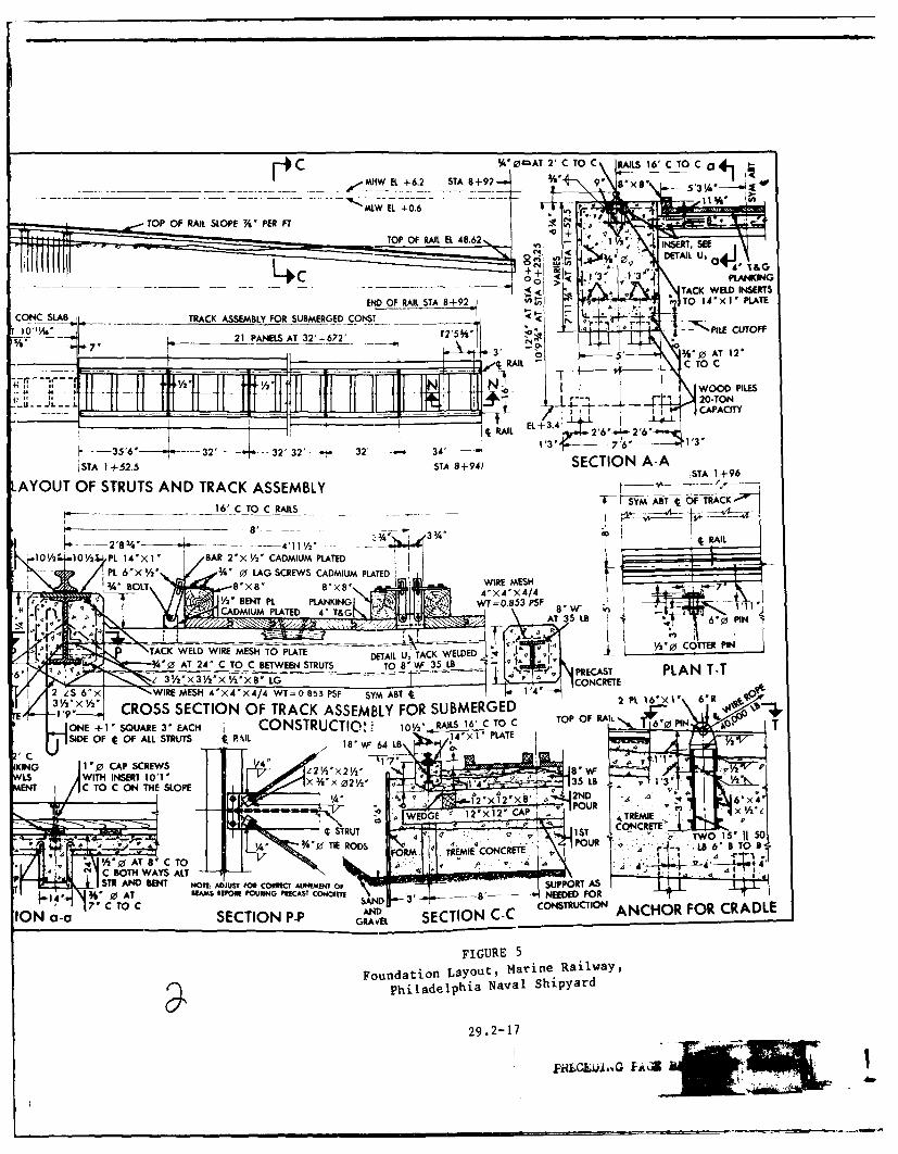
FIGURE 5
Foundation Layout, Marine Railway,
Philadelphia Naval Shipyard
29.2-17
PMLGLjAAG FA4~

4.,4
I ti
II
C4I
I *0
29.2-19P?.EC&4JAQ Fi
h- 2~------WASHER r I' TAP BOLXTS VAIE O__________ ~ OD,,5 K WTH OCKARIES (SEE DETAILSLO) 1K ITL
I~~AIE OOLT I.I'npt
3"1 -!
PLATE 3*
A- END1VIEW
21 2%
PIPET TO A-AELEATRUFTACCHEKERN.ADTUK HME
CATC WTEEL CS EN SMAT~EI
WITHCK TOCK It' - N" ASOUTID WIESNLLSSTEYCS
SLIDIN EFiLtMCPERSRN
_______PIP TO GE SEEL OS I
PIL L O B L O C . C A S lE O
OGRLCK PILLO kLC ANDDAREXPOSE SIJPAC DOF%-O
SECTIONID A-ANES STEEL WIHASA.ESST4
FIUR 7ISRE L
Typca Cradl Whe
is2 a.2-20
EJ~u".1.us 0IT CVER.CASTIRO

I
b. Wheel Bearings. For the larger marine railways, it is desirable toprotect the wheel bearings by rubber or other suitable pressure seals. Forsmall or medium sized marine railways, it is not necessary to provide protec-tion for the wheel bearings.
c. Axles. Make axles of medium carbon steel. Make bearings of castiron. Avoid combinations of metals that set up electrolytic action. Do notuse bushings of bronze, babbit, monel, or any other copper or nickel alloy.The best combination for bearings is cast iron on steel, with adequate provi-sion for lubrication. Pressure-sealed self-lubricating antifriction bearings,properly installed, will reduce the rolling friction.
Section 9. CRADLES
1. MATERIAL. Most cradle designs have steel frames with wood or steel deck-ing; however, timber cradles may be used for designs of small capacity. Atimber cradle requires ballast to counteract its buoyancy. Design steel cra-dles with few members and heavy sections to minimize the effect of corrosion.
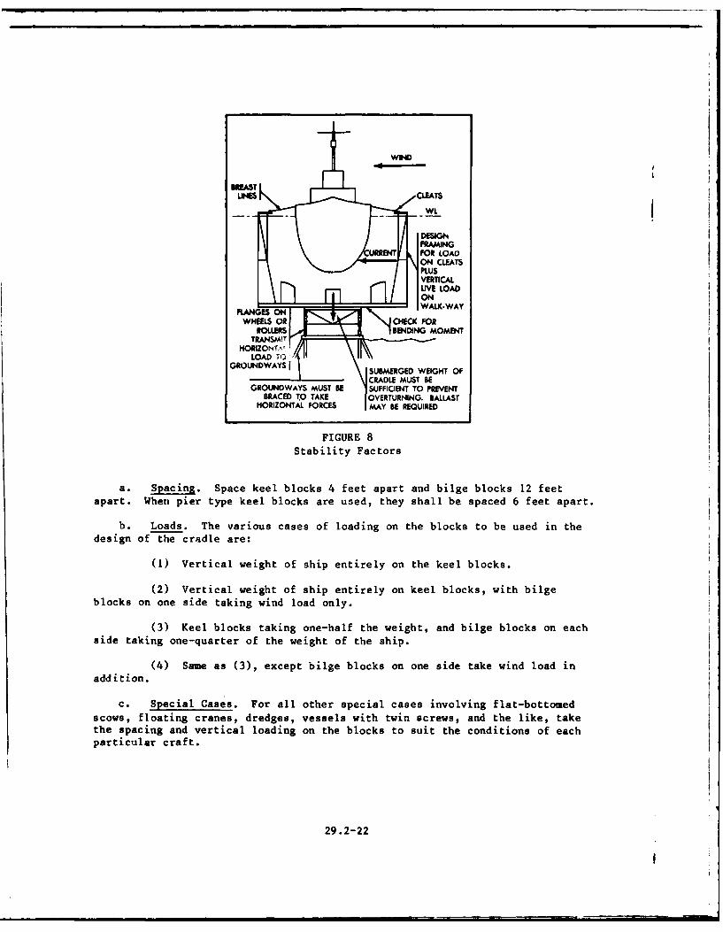
2. SHIP AND WIND LOADS. Design the cradle for a combination of loads aslisted in Section 6, and for loads occurring when the vessel is still afloatwith breast lines made fast to the cradle. (See Figure 8.) Under this condi-tion, consider concurrently the effects of wind and current forces in thedesign of the cradle superstructure. Also consider stability of the cradle onthe tracks under this condition. Use a wind velocity of 25 miles per hour todetermine the breast line pulls on the cradle. These pulls shall be increasedby 100 percent to allow for impact resulting from the motion of the vessel.
3. CHAIN PULLS. Design cradles to take pulls from hauling chains attached tothe crossarm. Provide transverse and longitudinal bracing to handle all load-ing conditions. The maximum pull on the chains shall be determined by equa-tion 1.
P = W sin b + WC (1)
Where: P - pull of chains (lb).W = total weight of maximum design vessel plus weight of cradle plus
weight of chains (Ib).= angle of inclination of way < (degrees).
C = coefficient of friction.
The coefficient of friction for rollers varies from 0.007 to 0.064 as indi-cated by tests at Boston and San Diego. Friction increases with: (1) theamount of silt, sand blast grit, and debris on the tracks; (2) wear and cor-rosion; (3) groundway deviations from grade and/or alinement; (4) lack of lu-brication and maintenance. For design life cycle basis, a coefficient of 0.04for rollers and 0.03 for wheels is satisfactory; however, larger values shouldbe used if above variables are expected to be unusually severe at a particularsite.
4. KEEL AND BILGE BLOCKS. In general, the requirements, arrangement, andfittings for blocking correspond to those required for docking vessels ingraving docks.
29.2-21I
WL
DESGNFRAMING
CURREFT FOR LOADON CLEATS
BVERTICALLIVE LOAD
D 5 1-4nlON
WHEELS ON CHECK FORROLLERS BEND11NG MOMENT
TRA N S MLT-
HORIZONTA 'LOAD TO3
GROUNDWAYS S UBMERGEDRDE uTWEIGHT OF
GROUNDWAY$ MUST BE SUFFICIENT TO PREVENTBRACED TO TAKE OVERTURNING. BALLAST
HORIZONTAL FORCES MAY BE REQUIRED
FIGURE 8
Stability Factors
a. Spacing. Space keel blocks 4 feet apart and bilge blocks 12 feetapart. When pier type keel blocks are used, they shall be spaced 6 feet apart.
b. Loads. The various cases of loading on the blocks to be used in the
design of the cradle are:
(1) Vertical weight of ship entirely on the keel blocks.
(2) Vertical weight of ship entirely on keel blocks, with bilgeblocks on one side taking wind load only.
(3) Keel blocks taking one-half the weight, and bilge blocks on eachside taking one-quarter of the weight of the ship.
(4) Same as (3), except bilge blocks on one side take wind load inaddition.
c. Special Cases. For all other special cases involving flat-bottomedscows, floating cranes, dredges, vessels with twin screws, and the like, takethe spacing and vertical loading on the blocks to suit the conditions of eachparticular craft.
29.2-22
d. Special Considerations.
(1) Bilge Blocks. Give consideration to the maximum outboard posi-tion of the loaded bilge blocks, and its effect on cradle design, especiallythe design of the cantilever portion of the transverse frames. Move bilgeblocks by hand winches located on the cradle walkway.
(2) Keel Blocks. Anchor keel blocks to prevent the possibility ofbeing overturned by the drag and surging of a vessel incident to the haulingoperation. Crib keel blocks at points of heavy load concentrations (such asthe afterknuckle of keel and at the forepoppet) to provide longitudinal sta-bility and adequate load distributions.
5. SPECIAL FRAMING OF OFFSHORE END. On some naval vessels, the propellers,sonar equipment, or rudders extend below the baseline or keel line. To accom-modate these vessels, it is necessary to design the cradle to provide suffi-
I cient clearance over the deck or pits for removal and replacement of suchequipment.
6. WALKWAYS. Provide elevated timber decked walkways on each side of thecradle, and on the larger railways, provide a crosswalk at the inner end.Make walkways level, about 3 feet wide, and at such an elevation that therewill be adequate freeboard when the cradle is in its extreme offshore posi-tion. Fit walkways with bilge block hauling mechanism, cleats and chocks,and/or ringbolts of ample size for securing the lines. Provide handrails onthe outboard side of the walkways.
7. WALKWAY UPRIGHTS. Walkway uprights of timber or steel support the walk-ways and form the sides of the cradle. Arrange them to assist in supportingstaging, and brace them to take the line pulls incident to centering and haul-ing vessels. (See Figure 8.) Because these loads are transmitted to the can-tilever portion of the main transverse frames, they must be considered in thedesign of the transverse frames.
8. CRADLE TRUSSES. Vertical members of cradle trusses are posts that carrythe vertical ship and dead load from the deck framing and docking blocks tothe bottom chord.
a. Top Chord. The top chord of the trusses is simply a tie to hold thefloor members in alinement.
b. Bottom Chord. The bottom chord requires special consideration. Itreceives loads from each post and, in turn, is supported by wheels or a rollertrain.
(1) Stresses. A large bending moment is generally developed in thebottom chord between posts when rollers are used, and it should be analyzed asa continuous beam. The portion of the bottom chord member that is forward ofthe inhaul girder will be in compression, and the portion that is aft will bein tension. Combine these stresses with those resulting from bending.
(2) Bracing. To maintain the cradle parts in alinement, providebracing in the plane of the bottom chord to take care of unequal resistance.
II 29.2-23
9. CRADLE FLOORS. A tight, nonslip type of steel floor may be used, althoughtimber decking is coinon practice. Effective means for collection and dis-posal of sand and incidental debris should be provided, because sandblastingcauses many problems in marine railway maintenance and the debris has a dele-terious effect on rollers, wheels, chains, chaintroughs, and tracks.
10. LADDERS. Provide ladders as necessary to permit access from cradle floorto walkways. Locate them on the inboard side of the walkway port and star-board.
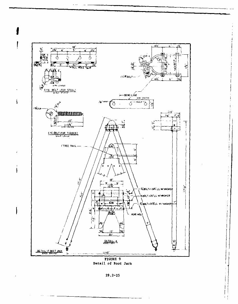
11. BOOTJACK. Provide a bootjack at the inner end of the cradle for use inlining up the bow of a ship preparatory to hauling. (See Figure 9.) Providea bootjack eyebolt on each side of the railway centerline on each cradletransverse frame for the inshore half of the cradle.
12. DRAFT GAGES. Provide at least two draft gages, one on each of the cradlewalkway structures, showing the depth of water over the end keel blocks.
13. FENDERS. Provide fenders along each inboard side of the walkway struc-ture.
14. ANCHORS. Install anchors (pad eye for wire rope) for cradles at the in-shore end of the groundways. These anchors are to be used to hold cradle ininboard position for maintenance and repair of the hauling mechanism.
15. DOCKING WINCHES. A motor operated winch may be installed on the center-line of the walkway at the shore end of a marine railway cradle to haul in thevessels. A special framework is required for mounting the winch at walkwaylevels. This limits the location of the bow of a ship, but where long cradlesare required, this limitation may not be critical. As an alternative arrange-ment, to avoid loss of docking length, provide two winches, one on each sideof the cradle superstructure.
Section 10. HAULING SYSTEMS
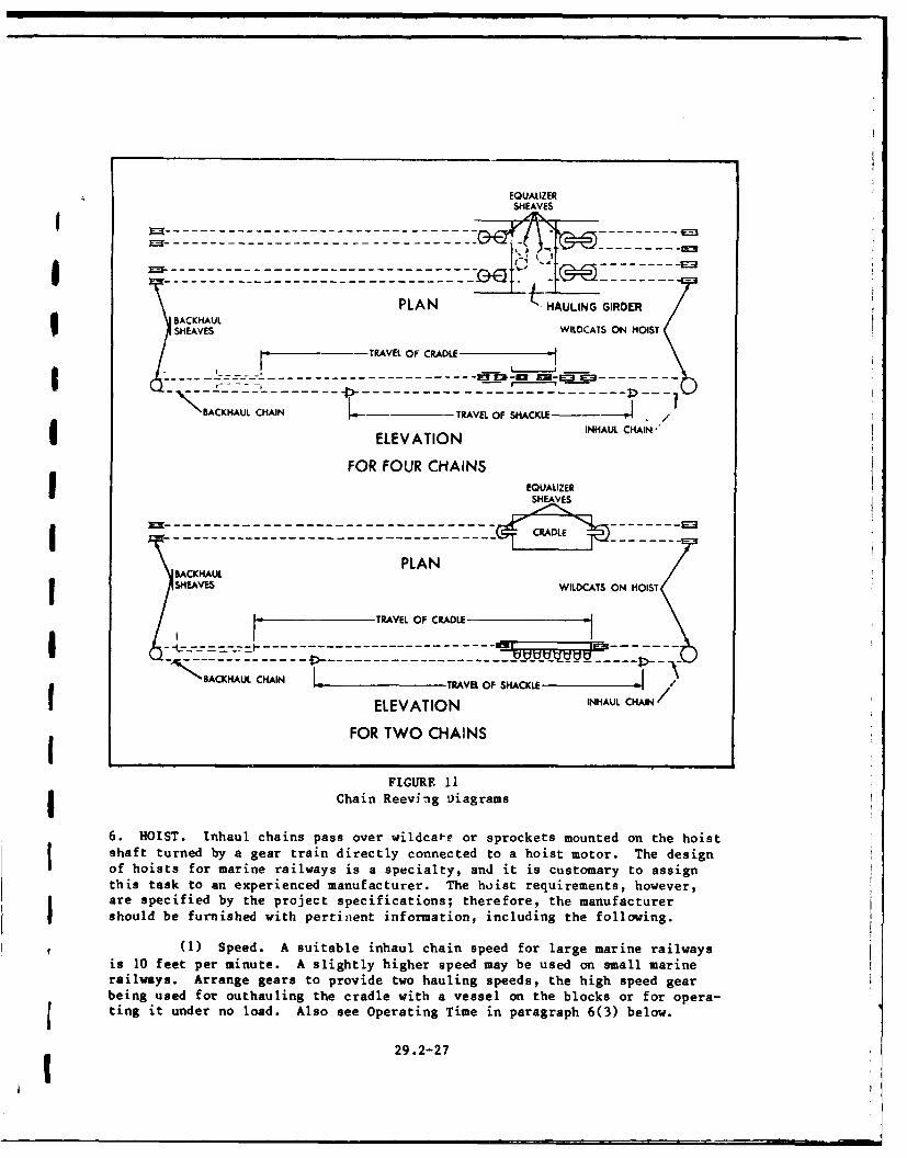
1. CHAIN REQUIREMENTS. Haul cradles with continuous chains running oversprockets or wildcats on the hoists. Provide two or four inhaul and two orfour outhaul chains (number of chains depends on capacity of marine railway)connected and reeved to form one endless chain. The pull on the chains isequalized by using an arrangement as shown in Figures 10 and 11.
2. HAULING GIRDER. Fasten the ends of both the inhaul and outhaul chains tothe cradle by a hauling girder. Into this girder incorporate the sheaves andother gear used to equalize the pull in the chains. Locate the hauling girderan the cradle so that it will be clear of the water when the cradle is in theinshore position.
3. INHAUL CHAINS. Use stud link chain of cast steel or dielock forged steel.
Lay out the chain reeving system in the form of a closed system. (See Figures10 and 11.) The size of the inhaul chains is determined by the load asdescribed below.
29.2-24
• i | " I' I ' I - e
W 72Y58 i 4fr 5"'
Ii~ ~~~Z.I t4BOLT--
E YE 13CLT FOR STEEL)SCAhE 3=r -
).--ENO LINE
'16 7'5
EYE SOLT(FOR TIM13ER)
I- VOLT, I W LG W1 VMSHEP
-A t)BOLT AWLC W/VASkIER
-- '~I-y48LT,20OVLG. YWY/WASH
ROM HOL
Z1"
FIGURE 9Detail of Boot Jack
29.2-25

EQUALIZER SHEAVE
----- -----CRADLE
ACKHAUL PLAN CHAINSPROCKET
SHEAVES FIXED ON HOISTINGTO LOWER END MACHINERYOF TRACK INHAUL CHAIN ......
----- --- zz1z 1SHACKLE0KSHACKLE
BACKHAUL CHAIN ELEVATION(A) TWO- CHAIN REEVING DIAGRAM
INHAUL DRUM- - -DOWNHAUL
... .-E-:q DRUM
'CLUTCHPLAN INHAUL DRUMSHEAVE FIXED
TO LOWER ENDOF TRACK
. . .. . .. . . . . . - __ --.. *..e', - --
''-
..--
-- --
- -- - - - --
-'m
ELEVATION(B) T WO- PART WIRE ROPE REEVING DIAGRAM
FIGURE 10
Marine Railway Hauling Systems
a. Working Strength. Take the working strength of the chain at 35 per-
cent of its breaking strength.
b. Number and Size of Chains. Determine the number of chains from com-
puted pull calculations. (See Section 9.) When chains are larger than 2-1/4
or 2-1/2 inches, they become unwieldy. Therefore, if the pull is such that
two 3-inch chains are required, use four 2-1/4-inch chains.
4. OUTHAUL CHAINS. Design outhaul chains (the portion that hauls the cradle
out and down the track) for the load required to overcome starting inertia.
For outhaul chains, use a minimum size of I inch. On larger marine railways,
1-1/4-inch chain may be used.
5. OUTHAUL SHEAVES. Locate outhaul sheaves at the extreme offshore end of
the groundways, and anchor them to the groundways. Make them readily demount-
able, and design sheave and anchorage to develop full breaking strength of
backhaul chains.
29.2-26
EQUALIZERSHEAVES
g-----------------\---7-PLAN HAULING GIRDER
BACK HAULSHEAVES WILDCATS ON HOIST
-TRAVEL OF CRAML
- -, - - - -- -
BACKNAUL CHAIN - TRAVEL OF SH-ACKLE -ELEVATIONEQAIR CAI
FOR FOUR CHAINS
SHEAVES.
CRADLE
ACKHAUL PLAN
TRAVEL OF CRADLE
---- ---- --- ------ ----------------- -- --- -_NSACKHAUL CHAIN L ..v a SHACKLE
ELEVATION INHAUL CHAIN"
FOR TWO CHAINS
FIGURE 11Chain Reeving oiagrams
6. HOIST. Inhaul chains pass over wildcat-e or sprockets mounted on the hoistshaft turned by a gear train directly connected to a hoist motor. The design
of hoists for marine railways is a specialty, and it is customary to assignthis task to an experienced manufacturer. The hoist requirements, however,
are specified by the project specifications; therefore, the manufacturer
should be furnished with pertinent information, including the following.
(1) Speed. A suitable inhaul chain speed for large marine railwaysis 10 feet per minute. A slightly higher speed may be used on small marinerailways. Arrange gears to provide two hauling speeds, the high speed gearbeing used for outhauling the cradle with a vessel on the blocks or for opera-ting it under no load. Also see Operating Time in paragraph 6(3) below.
29.2-27
(2) Brakes. Provide hoists with an electric automatic motor brake,an emergency handbrake, and a lever operated pawl engaging in a ratchet, alldesigned to hold the loaded cradle in any position on the ways. Provide limitswitches to prevent overrun.
(3) Operating Time. The capacity of the hauling machinery or hoistshould be such that it will haul up the loaded cradle in from 10 to 15 minutesfor railways up to 500-ton capacity, and in about 30 minutes for larger rail-ways.
a. Lubrication. Particular .ttention should be given the design of thelubrication system for all the bearings and gears.
b. Efficiency. Assuming that the total efficiency of a pair of gears,including journal losses, is 0.935, the overall efficiency of a marine railwayhoist with four pairs of gears would be about 75 percent. Because machineryof this type should be designed with ample power, assume, in this case, anoverall efficiency of 65 percent, corresponding to an efficiency of 0.90 foreach pair of gears. The efficiency of machines outfitted with antifrictionbearings is somewhat higher.
c. Special Precautions. Install the hoist with great care and accuracy.The hoist frame must rest upon a rigid foundation, and must be carefully setand held in place by anchor bolts of ample size. Exercise great care in thedesign of the frame of the hoist, to provide for all phases of operation whichcould cause misalinement. When misalinement occurs, gears, bearings, andshafts are subject to great overstress and the hoist may deteriorate rapidly.
7. HOIST FOUNDATION. Design the hoist foundation to take the horizontal andvertical components and impact of the maximum chain pull and the overturningmoment. (See Figure 12.)
a. Rock Support. Where hoist foundations are supported on rock, trans-fer the horizontal load by keying the concrete foundation into the rock.
b. Pile Support. Where foundations are supported by piles, L:ansfer thehorizontal load to the subsoil by means of batter piles.
c. Stresses. With respect to the internal stresses in the foundationblock, a very careful analysis of the moments and shears is necessary to assurean adequate amount of reinforcing steel and properly designed anchor bolts.
d. Cracking. To prevent foundation cracking as a result of shrinkage,provide minimum reinforcing steel equivalent to 0.3 percent of the area of thehorizontal and vertical cross sections.
8. MOTOR. The motor shall be of the woundrotor induction type for operation
on 3-phase voltage, and of dripproof construction. Base the horsepower powerrating on intermittent operation at full load with a resultant temperaturerise of not more than 40 degrees centigrade and having a breakdown torque ofapproximately 250 percent of full load torque. Select the motor to be ofmoisture resistant design, and provide space heaters of sufficient capacit) tohold the temperature at approximately 5 degrees centigrade above the ambient,as a protection against dampness.
29.2-28

F
CHAIN PULL
'DEAD WEIGHTJOF HOIST ANDFOUNDATION
t MUST BESUFFICIENTHORIZONTAL PULL VERTICAL PULL TO RESIST
IS RESISTED BY OVERTURNING
BATTER PILES MOMENT WITH
SUPPORT ON PILES FACTOt OFSAFETY
SUPPORT ON ROCK
FIGURE 12
Hoist Foundation
Section 11. CONTROL EQUIPMENT
1. REQUIREMENTS. Obtain electric power from shore distribution systems.
Build control equipment as metal enclosed units insofar as practicable.
2. LINE PROTECTIVE EQUIPMENT. Provide line protective equipment with proper
interrupting capacity and having overload and low voltage protection. In ad-dition, include: (1) integrating watt-hour meter, (2) recording wattmeter,
(3) indicating lights, and (4) ammeter installed at master control switch
location.
3. PRIMARY CONTROL EQUIPMENT. Provide primary control equipment for forward
and reverse operation and plugging. In addition, include all other devicesnecessary for control of the primary circuit of the motor.
4. SECONDARY CONTROL EQUIPMENT. Provide secondary control equipment for
automatic control of the acceleration by definite time limit devices arranged
for master switch operation. Provide an adjustable notch back device so that,at a selected overload value of current, the control will automatically insert
one resistance step in the secondary circuit and later automatically removethe resistance when the current returns to a normal value.
5. SECONDARY RESISTORS. Select secondary resistors for the duty encountered
in operation. Construct resistors of corrosion resistant material.
Li 29.2-29

6. MASTER CONTROL SWITCH. Provide a master control switch with sufficientpoints in each direction to insure smooth operation of the railway, with atleast one point of regenerative lowering during which the motor will operateslightly above synchronous speed, and the remaining points equipped withcountertorque control for retarding the load. The OFF position of the switchshall disconnect the motor and apply the brake.
7. EMERGENCY CONTROL. Provide a manually operated emergency control switchat a location convenient to the operator. This switch shall disconnect thecontrol circuit and apply the brake.
8. OVERSPEED AND LIMIT SWITCHES. Provide overspeed and limit switches. Inaddition, provide a pawl, used for mechanically holding the load in case ofbrake failure, with a limit switch to prevent operation of the hoist motor inthe direction which would damage the equipment when the pawl has not been dis-engaged.
9. BRAKES. Provide smooth functioning direct current magnetic type brakes,operated by a rectifier.
Section 12. MACHINERY HOUSE
1. REQUIREMENT. Design the machinery house as a one-story building of amplefloor area to contain the hauling machinery, switchboard, and other equip-ment. The construction details are as follows:
(1) Provide an access door, and at least one large door to permiteasy removal of machinery. The house shall have necessary windows for lightand ventilation and to permit the operator a full view of the cradle and ways.
(2) For a 2,500-ton marine railway, the machinery house should beapproximately 27 feet wide and 25 feet long with 9 feet headroom. (SeeSection 5 for size of hoist house for a 3,000-ton marine railway.)
(3) Provide case iron guide thimbles for the bottom of chains in thesidewalls, and provide a steel wearing plate for the top of the chains.
(4) Machinery pits shall be properly sized and drained, and fur-nished with necessary handrails and guards.
(5) The building may be of light noncombustible construction unlessother considerations justify more substantial building.
(6) Facilities for removing machinery are necessary, and may consistof a hand operated crane in the building or a removable skylight or hatch overthe hoist to permit the use of an outside crane.
29.2-30
Section 13. FACILITIES
1. TRACKS. Install a standard gage track along one side of the marine rail-way so that materials and equipment may be delivered to or from a traveling
crane. Where the yard is equipped with adequate trucking facilities, thistrack may not be necessary. (See Figure 4.)
2. DOLPHINS AND APPROACH PIERS. Because of severe local wind, tide, or cur-rent conditions, it may be necessary to temporarily moor or guide vessels intothe cradle. This function can be provided by means of piers, but the mostusual method is to install dolphins or platforms beyond the offshore end ofthe groundways.
i 3. SANITATION. Toilets and washrooms for the ship's crew and for workmenmust be convenient to the marine railway, and shall be provided unless ade-quate facilities are present in existing buildings.
I 4. SERVICES. Provide services through extensions from shore systems. Extendthe mains approximately the full length of the cradle in its inboard position.They may be placed in a trench or tunnel which may be located on one side ofthe marine railway, the position being determined to some extent by the loca-tion of source of supply. The design shall provide adequate protectionagainst freezing. Install service pits approximately every 50 feet for thefull length of the mains. The services should include the following:
a. Fresh Water. Mains shall have a manifold at each service pit, pro-vided with one 2-1/2-inch valved outlet with cap and chain. The residualpressure at any outlet shall be 40 to 80 pounds per square inch.
b. Salt Water Flushing and Fire Protection. Mains shall have a manifoldat each service pit, provided with one 4-1/2-inch valved pumper connection,one 2-1/2-inch valved outlet, all with caps and chains. The residual pressureat the outlets shall be not less than 40 pounds per square inch.
C. Steam. Mains shall be 4 inches in size, and have one 2-1/2-inchvalved outlet, with cap and chain, at each service pit. The residual steampressure at the outlets should be approximately 150 pounds per square inchgage.
d. Compressed Air. Mains shall be 4 inches in size, and have a manifoldat each service pit equipped with one 2-1/2-inch valved outlet with cap andchain. The air pressure at the outlets should be approximately 100 pounds per
square 1,ich.
e. Electrical Power. Weatherproof convenience receptacle stations shallbe installed alongside the marine railway for single and three phase 60 Hertzpower as required.
5. LIGHTING. For night lighting of the cradle, 250 candlepower lights (withreflectors), spaced about 60 feet apart on each side, are required. Attachthese to the walkway supports. Connect the lighting circuit to the streetlighting system of the yard. Also provide necessary lighting for the railwayand floodlighting for night dockings in addition to that on the cradle.
29.2-31I

Section 14. SIDEHAUL MARINE RAILWAY
1. MULTIPLE CRADLES. The design of a sidehaul marine railway is similar tothat of an endhaul marine railway, but there are special conditions to beconsidered. It is customary to provide two or more cradles to make itpossible to dock or undock more than one small vessel independently. Whenmultiple cradles are used, equalization of pulls on inhaul chains becomes ofspecial importance.
2. 3,000-TON FACILITY. For this installation, there are 12 cradles, 12 setsof groundways, and 12 hoists. (See Figures 13, 14, and 15.) The control sys-tem for the hoists is arranged so that any number of cradles can be operatedtogether or separately as necessary to dock ships of various lengths.
HAND BI l .LGE" WARPING BLOCKSWIN " INCH
• SNATCH BLOCK
FIGR BLOCOPERATING
CHAINS
BLOCK KEEL TRASFE
BLOCKS CARRIAGE ihSHEAVES FOR
prcia/ ein n oa nest sue o eigtrale an as heaie
UOSHUNT
CARRIAGE
CRADLE/CRADLE ,
RUNWAY .-.
FIGURE 13Section Through Sidehaul Marine Railway
a. Design Load. Figure 14 shows the design load divided into 12 partslongitudinally, and each cradle designed to take a part of the load. Forpractical design, one load intensity is used for eight cradles and a heavier
one for four cradles. The cradles designed to take the heavier loads aremarked Heavy Cradles on Figure 14. Similarly, the various sets of groundways
are designed for the two different loadings.
29.2-32

Iv
I 26,800 LB
22,300 LB
HEAVY DESTROYER 10,840 LITOTAL WEIGHT 2,864 GT
7,080 LB 4,680 LB
FRAME SPACES
200 180 160 140 120 100 80 60 40 20 0
~23,300 LB20,550 LO 1,7
13,650 L I 16,120 LO L
'go L ~LIGHT DESTROYER1020L5,990 LB TOTAL WEIGHT 2,246 GT
FRAME SPACES
180 160 140 120 100 80 60 40 20 0
28,380 LB
21,270 LB ALL CRADLE LOADS OBTAINED BY SIMPLE
BEAM DISTRIBUTION
1,340 LB AT TUG 11,170 B AVERAGE LOADS AND PULLSTOTAL WEIGHT 1,453 GT 3,000 (6.6) + 430 (SHUNT) + 349 (CRA'nLES) = 3,779 GT
4s4O0LB AVERAGE LOAD - 3,779 + 12 - 315 GTAVERAGE PULL 132.5 KIPS (CRADLE| - 66 KIPS (EACH CHAIN)
15' 17'6'HEAVY CRADLES "* -.-Z..Z 17'6 15,
Lii L LJLJIULJCRADLE NUMBERS12 1 10 9 a 6 5 4 3 2 1 CRADLE LOADS AND CHAIN PULLS
0 24 401 334 324 324 324 330 376 241 117 69 HEAVY DESTROYER GT
0 19 331 305 298 278 234 269 293 134 67 18 LIGHT DESTROYER GT
131 303 405 326 207 II AT TUG GT
334 405 405 334 334 334 334 334 405 405 334 334 DESIGN CRADLE LOADN GT
334 405 405 334 334 334 334 334 405 405 117 69 CRADLE LOADS GT
36 36 36 36 36 36 36 36 36 36 36 36 WT SHUNT CARRIAGE GT
27 34 34 27 27 27 27 27 34 34 27 27 WT OF CRADLE GT
397 475 475 397 347 397 397 347 475 475 397 397 TOTALS
166 199 195 166 166 166 166 166 199 199 166 166 DESIGN CRADLE PULL (KIPS)
100 100 100 100 100 100 100 100 100 100 100 100 DESIGN CHAIN PULL IKIPS)
FIGURE 14
Cradle Loads and Chain Pulls
29.2-33

I - z
~ z.
-1C
ik
91 Mi I hIN p
P 11 1
: P
;I it Ni_ _ _
II
I
___ ___ I l,
Ii
"
ii
C-3
315' 29F'- ' - 329
TRANSF ER CARIGE WATER LINE W 1-
D C IG C R IA EHAULED
ONTO DOOKING AREA
FIGURE 15Sidehaul Marine Railways
b. Synchronization. The use of 12 cradles and 12 hoists requires anelectrical system designed to synchronize the movement of the cradles. It wasfound that when a vessel was docked on this marine railway, the loads on thevarious cradles vary considerably. This variation produces a dissimilarity inchain load and chain stretch, tending to cause the more heavily loaded cradlesto lag behind as they came up the track. A special design of the electricalsystem permits the lagging cradles to be pulled up even with the others whennecessary. The design of this particular marine railway also provides for
29.2-34
shunt and transfer carriages to permit vessels to be hauled off the cradle forrepair in the yard. In this manner, as many as four vessels could be repaired
at one time.
Section 15. DRAWINGS AND SPECIFICATIONS
1. REFERENCES. NAVFAC specifications and drawings contain data on marinerailways designed and constructed under the cognizance of NAVFAC HQ. Futuredesigns may be modified because of improvements in design and materials forhoist motors, electrical controls, machinery design, chains, and other fea-tures. Characteristics of existing naval marine railways are presented inNAVFAC DM-29.3.
2I
(
I29.2-35
I'

GLOSSARY
Bilge. The curve of a ship's hull joining the side and the bottom.
Bootjack. An A-frame for lining up the bow of a ship to assist hauling intolongitudinal and transverse position over a marine railway cradle when inoutboard position.
Captive Crane. A traveling crane limited to use at one facility because ofthe absence of track connections to other facilities.
Cribbing. A framework, usually of timber, designed to distribute concentratedship loads and to provide longitudinal stability to the keel blocks.
Gypsy Head. A small auxiliary drum at the side or top of a winch.
Keel. The principal bottom structural element of a ship extending along thecenterline for the full length of the ship.
Poppet. Special construction at the ends of a ship's launching cradle. Thepoppets resist careening when the ship moves down the ways, and the fore-poppet takes the concentrated loading induced when the ship rotates aboutthis poppet when the stern is lifted by buoyancy.
Skeg. Vertical projection extending below the hull of a vessel to reduceyawing.
Sonar Dome. A bulge or appendage on the keel of a ship, usually forward, forhousing sonar equipment.
Wildcat. A pocketed and slotted wheel on a winch over which a chain passes.
Winch (or Windlass). An engine fitted with a rotating drum for hauling ropes.Some are fitted with multiple drums, a gypsy head for hauling ropes, or awildcat for hauling chains.
Glossary-I
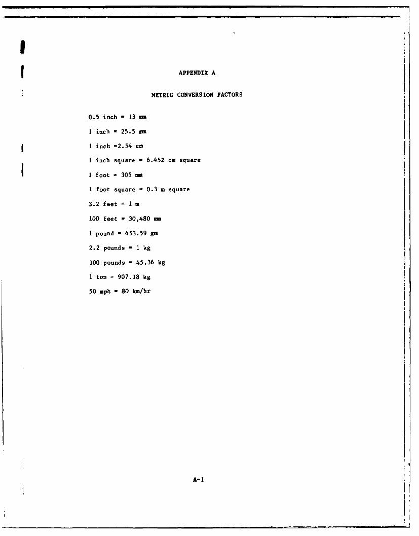
I
(APPENDIX A
METRIC CONVERSION FACTORS
0.5 inch - 13 m
1 inch - 25.5 m
I inch =2.54 cm
I inch square - 6.452 cm square
1 foot = 305 mm
1 foot square - 0.3 m square
3.2 feet = 1 m
100 feet = 30,480 -
1 pound - 453.59 gm
2.2 pounds = 1 kg
100 pounds - 45.36 kg
1 ton = 907.18 kg
50 mph = 80 km/hr
A-I
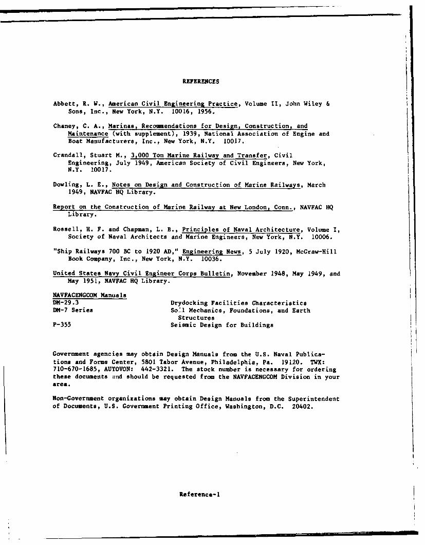
REFERENCES
Abbett, R. W., American Civil Engineering Practice, Volume 11, John Wiley &Sons, Inc., New York, N.Y. 10016, 1956.
Chaney, C. A., Marinas, Recomendations for Design, Construction, andMaintenance (with supplement), 1939, National Association of Engine andBoat Manufacturers, Inc., New York, N.Y. 10017.
Crandall, Stuart M., 3,000 Ton Marine Railway and Transfer, CivilEngineering, July 1949, American Society of Civil Engineers, New York,N.Y. 10017.
Dowling, L. E., Notes on Design and Construction of Marine Railways, March1949, NAVFAC HQ Library.
Report on the Construction of Marine Railway at New London, Conn., NAVFAC HQLibrary.
Rossell, H. F. and Chapman, L. B., Principles of Naval Architecture, Volume I,Society of Naval Architects and Marine Engineers, New York, N.Y. 10006.
"Ship Railways 700 BC to 1920 AD," Engineering News, 5 July 1920, McGraw-HillBook Company, Inc., New York, N.Y. 10036.
United States Navy Civil Engineer Corps Bulletin, November 1948, May 1949, andMay 1951, NAVFAC HQ Library.
NAVFACENGCOM ManualsDM-29.3 Drydocking Facilities CharacteristicsDM-7 Series So.l Mechanics, Foundations, and Earth
StructuresP-355 Seismic Design for Buildings
Government agencies may obtain Design Manuals from the U.S. Naval Publica-tions and Forms Center, 5801 Tabor Avenue, Philadelphia, Pa. 19120. TWX:710-670-1685, AUTOVON: 442-3321. The stock number is necessary for orderingthese documents and should be requested from the NAVFACENGCOM Division in yourarea.
Non-Government organizations may obtain Design Manuals from the Superintendent
of Documents, U.S. Government Printing Office, Washington, D.C. 20402.
Reference-I

FILMED
ITI