Embed Size (px)
Citation preview
MME 345
Lecture 09
Solidification and Crystallisation6. Segregation and gas porosity
Ref:
[1] A. Ohno, The Solidification of Metals, Chijin Shokan Co. Ltd., 1976
[2] J. Campbell, Castings, Butterworth-Heinemann, 2001
Topics to discuss today ….
1. Segregation
2. Gas porosity
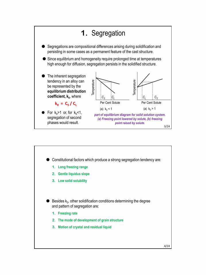
1. Segregation
Segregations are compositional differences arising during solidification and
persisting in some cases as a permanent feature of the cast structure.
Since equilibrium and homogeneity require prolonged time at temperatures
high enough for diffusion, segregation persists in the solidified structure.
Tem
pera
ture
Per Cent Solute
CS CL
(a) k0 < 1
Tem
pera
ture
Per Cent Solute
CL CS
(a) k0 > 1
part of equilibrium diagram for solid solution system.
(a) Freezing point lowered by solute, (b) freezing
point raised by solute.
The inherent segregation
tendency in an alloy can
be represented by the
equilibrium distribution
coefficient, k0, where
k0 = CS / CL
For k0>1 or, for k0<1,
segregation of second
phases would result.3/24
Constitutional factors which produce a strong segregation tendency are:
1. Long freezing range
2. Gentle liquidus slope
3. Low solid solubility
Besides k0, other solidification conditions determining the degree
and pattern of segregation are:
1. Freezing rate
2. The mode of development of grain structure
3. Motion of crystal and residual liquid
4/24
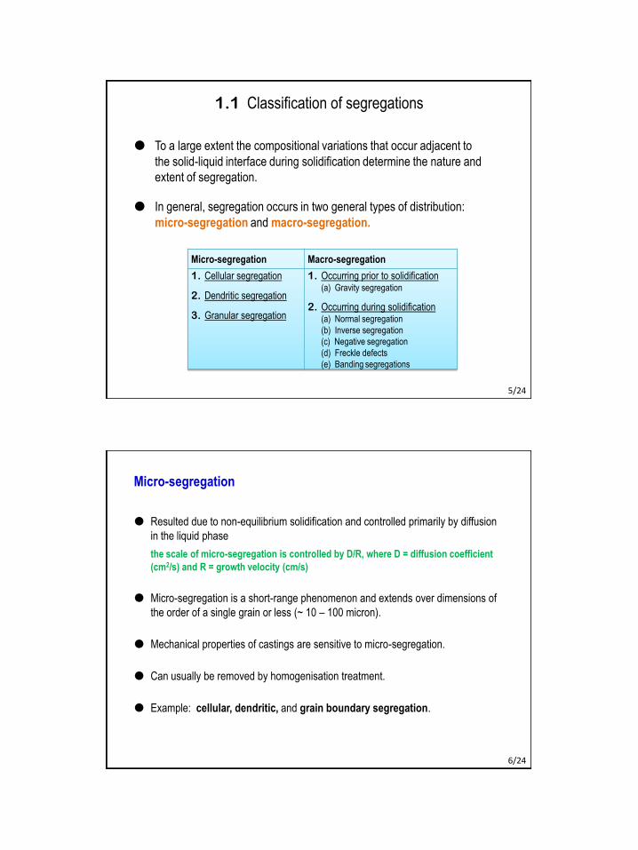
1.1 Classification of segregations
To a large extent the compositional variations that occur adjacent to
the solid-liquid interface during solidification determine the nature and
extent of segregation.
In general, segregation occurs in two general types of distribution:
micro-segregation and macro-segregation.
Micro-segregation Macro-segregation
1. Cellular segregation
2. Dendritic segregation
3. Granular segregation
1. Occurring prior to solidification(a) Gravity segregation
2. Occurring during solidification(a) Normal segregation
(b) Inverse segregation
(c) Negative segregation
(d) Freckle defects
(e) Banding segregations
5/24
Micro-segregation
Resulted due to non-equilibrium solidification and controlled primarily by diffusion
in the liquid phase
the scale of micro-segregation is controlled by D/R, where D = diffusion coefficient
(cm2/s) and R = growth velocity (cm/s)
Micro-segregation is a short-range phenomenon and extends over dimensions of
the order of a single grain or less (~ 10 – 100 micron).
Mechanical properties of castings are sensitive to micro-segregation.
Can usually be removed by homogenisation treatment.
Example: cellular, dendritic, and grain boundary segregation.
6/24

Macro-segregation
Macro-segregation refers to zonal segregation of solute in different parts of casting
occurring over a long distance ranging from 1 cm to 1 m and, therefore, can not be
removed.
Result either from changes that occur in the liquid before the solidification front has
proceeded or as the result of fluid motion in the mushy zone behind the solidification
front
Thus, the processes leading to zonal segregation may include:
1. diffusion of impurities from two phase zone of solidifying casting within the still
liquid alloy,
2. convection of alloy streams in the liquid portion of the casting,
3. floating of low density impurity, and
4. action of centrifugal forces.
Example: normal or positive segregation (or, coring), V-segregation, inverse
V-segregation, negative segregation, surface segregation.
7/24
Normal / Positive Segregation
Castings contain high concentrations of low-melting
solute at the central portion of ingot due to solute
rejection at the interface and accumulation at the centre.
This inhomogeneous structure is often called coring
Freezing of quiescent liquid:
During initial stages, solids form with a composition
k0C0, and solute builds up ahead of the front in the
liquid.
Subsequent freezing to solid of composition C0
takes place in a steady, continuous fashion.
In the final stages, segregation of solute in both solid
and liquid increases.
distribution of solute during solidification when there is no diffusion in solid and when solute moves only by diffusion in the liquid
8/24
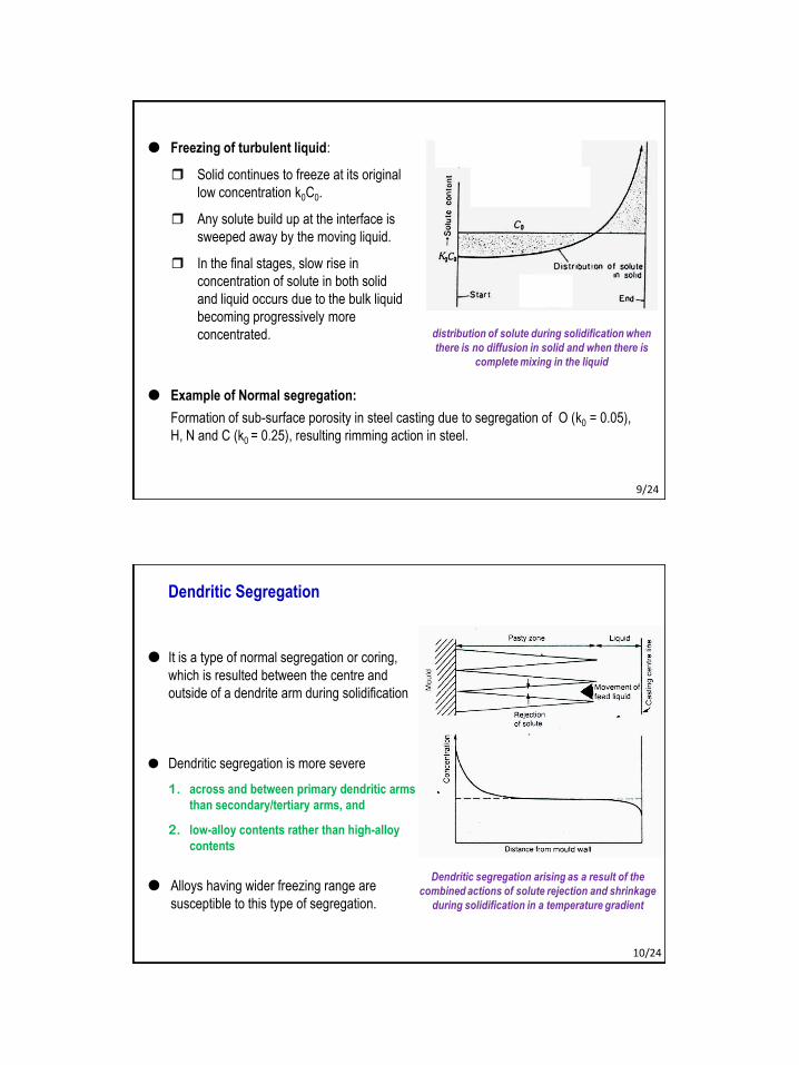
Freezing of turbulent liquid:
Solid continues to freeze at its original
low concentration k0C0.
Any solute build up at the interface is
sweeped away by the moving liquid.
In the final stages, slow rise in
concentration of solute in both solid
and liquid occurs due to the bulk liquid
becoming progressively more
concentrated.
Example of Normal segregation:
Formation of sub-surface porosity in steel casting due to segregation of O (k0 = 0.05),
H, N and C (k0 = 0.25), resulting rimming action in steel.
distribution of solute during solidification when
there is no diffusion in solid and when there is
complete mixing in the liquid
9/24
Dendritic Segregation
It is a type of normal segregation or coring,
which is resulted between the centre and
outside of a dendrite arm during solidification
Dendritic segregation arising as a result of the
combined actions of solute rejection and shrinkage
during solidification in a temperature gradient
Alloys having wider freezing range are
susceptible to this type of segregation.
Dendritic segregation is more severe
1. across and between primary dendritic arms
than secondary/tertiary arms, and
2. low-alloy contents rather than high-alloy
contents
10/24
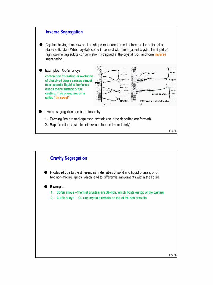
Crystals having a narrow necked shape roots are formed before the formation of a
stable solid skin. When crystals come in contact with the adjacent crystal, the liquid of
high low-melting solute concentration is trapped at the crystal root, and form inverse
segregation.
Inverse segregation can be reduced by:
1. Forming fine grained equiaxed crystals (no large dendrites are formed).
2. Rapid cooling (a stable solid skin is formed immediately).
Inverse Segregation
Examples: Cu-Sn alloys
contraction of casting or evolution
of dissolved gases causes almost
near-eutectic liquid to be forced
out on to the surface of the
casting. This phenomenon is
called “tin sweat”
11/24
Gravity Segregation
Produced due to the differences in densities of solid and liquid phases, or of
two non-mixing liquids, which lead to differential movements within the liquid.
Example:
1. Sb-Sn alloys – the first crystals are Sb-rich, which floats on top of the casting
2. Cu-Pb alloys – Cu-rich crystals remain on top of Pb-rich crystals
12/24
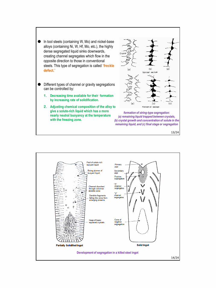
formation of string-type segregation:
(a) remaining liquid trapped between crystals,
(b) crystal growth and concentration of solute in the
remaining liquid, and (c) final stage or segregation
Different types of channel or gravity segregations can be controlled by:
1. Decreasing time available for their formation
by increasing rate of solidification.
2. Adjusting chemical composition of the alloy to
give a solute-rich liquid which has a more
nearly neutral buoyancy at the temperature
with the freezing zone.
In tool steels (containing W, Mo) and nickel-base
alloys (containing Ni, W, Hf, Mo, etc.), the highly
dense segregated liquid sinks downwards,
creating channel segregates which flow in the
opposite direction to those in conventional
steels. This type of segregation is called “freckle
defect.”
13/24
Development of segregation in a killed steel ingot
14/24
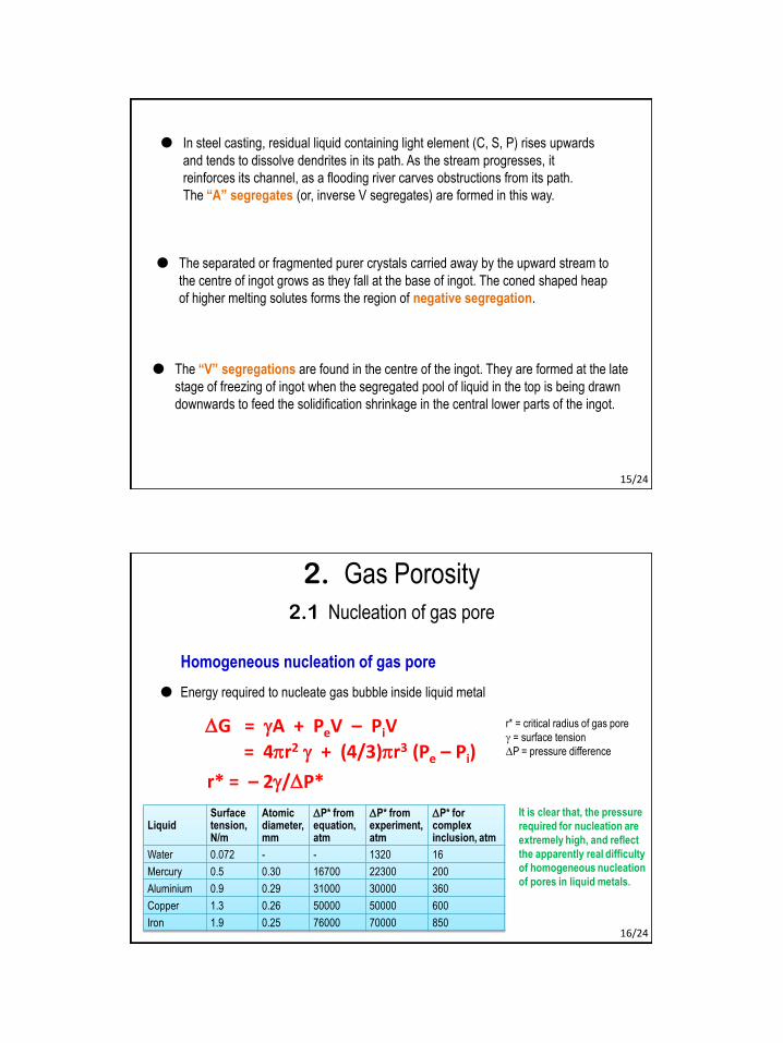
In steel casting, residual liquid containing light element (C, S, P) rises upwards
and tends to dissolve dendrites in its path. As the stream progresses, it
reinforces its channel, as a flooding river carves obstructions from its path.
The “A” segregates (or, inverse V segregates) are formed in this way.
The separated or fragmented purer crystals carried away by the upward stream to
the centre of ingot grows as they fall at the base of ingot. The coned shaped heap
of higher melting solutes forms the region of negative segregation.
The “V” segregations are found in the centre of the ingot. They are formed at the late
stage of freezing of ingot when the segregated pool of liquid in the top is being drawn
downwards to feed the solidification shrinkage in the central lower parts of the ingot.
15/24
r* = critical radius of gas pore
g = surface tension
DP = pressure difference
Homogeneous nucleation of gas pore
r* = – 2g/DP*
DG = gA + PeV – PiV
Energy required to nucleate gas bubble inside liquid metal
LiquidSurface tension,N/m
Atomic diameter,mm
DP* from equation,atm
DP* from experiment,atm
DP* forcomplex inclusion, atm
Water 0.072 - - 1320 16
Mercury 0.5 0.30 16700 22300 200
Aluminium 0.9 0.29 31000 30000 360
Copper 1.3 0.26 50000 50000 600
Iron 1.9 0.25 76000 70000 850
It is clear that, the pressure
required for nucleation are
extremely high, and reflect
the apparently real difficulty
of homogeneous nucleation
of pores in liquid metals.
= 4pr2 g + (4/3)pr3 (Pe – Pi)
2.1 Nucleation of gas pore
2. Gas Porosity
16/24

The problem of nucleation is reduced by the presence of surface-active
non-metallic impurities (O, S, P) in iron.
Presence of only 0.2 % oxygen reduces the value of surface tension from
1.9 to 1.0 N/m.
Partition coeff. of oxygen is 0.05. This means that if the liquid contains only
about 0.01 % O, due to segregation, the bulk liquid can have about 0.2 % O.
If the oxygen content is sufficiently high to produce FeO, the value of surface
tension is reduced further to about 0.6 N/m.
So to nucleate a gas bubble a pressure of only about 17000 atm is required in
presence of FeO
17/24
q = contact angle
Heterogeneous nucleation of gas pore
Heterogeneous nucleation of gas bubble on the surface of solid substrate
liquid metal
gas bubble
solid substrate
Nucleation is easier by a factor
DP*het / DP*hom = 1.122 + 3cosq - cos3q
4
1/2
18/24
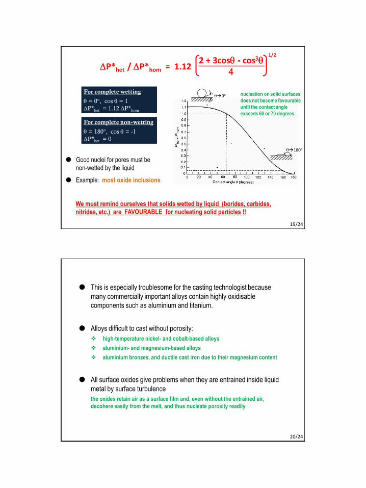
For complete wetting
q = 0°, cos q = 1
DP*het = 1.12 DP*hom
For complete non-wetting
q = 180°, cos q = -1
DP*het = 0
Good nuclei for pores must be
non-wetted by the liquid
Example: most oxide inclusions
We must remind ourselves that solids wetted by liquid (borides, carbides,
nitrides, etc.) are FAVOURABLE for nucleating solid particles !!
DP*het / DP*hom = 1.122 + 3cosq - cos3q
4
1/2
q0o
q180o
nucleation on solid surfaces
does not become favourable
until the contact angle
exceeds 60 or 70 degrees.
19/24
This is especially troublesome for the casting technologist because
many commercially important alloys contain highly oxidisable
components such as aluminium and titanium.
Alloys difficult to cast without porosity:
high-temperature nickel- and cobalt-based alloys
aluminium- and magnesium-based alloys
aluminium bronzes, and ductile cast iron due to their magnesium content
All surface oxides give problems when they are entrained inside liquid
metal by surface turbulence
the oxides retain air as a surface film and, even without the entrained air,
decohere easily from the melt, and thus nucleate porosity readily
20/24

Controlled by the rate of diffusion of
gases through the liquid metal
the rate of growth is dominated by the
rate of arrival of the fastest diffusing gas
diffusion coefficients for elements
in aluminium and copper
2.2 Growth of gas porosity
Hydrogen has a diffusion coefficient
almost 10 times higher than that of any
other element in solution
Diffusion distance, d (Dt) 1/2
Radius of H bubble 101/2 3 times greater
Volume of H bubble 33 30 times greater
this is why [H] has the dominant influence
over the growth of gas pores
Remember:
[O] is the dominant element for
nucleating a gas pore !!21/24
The final amount of gas pore can be determined by (1) the time available for gas to diffuse
into the pore and (2) the well-known gas law:
PV = nRT
Final volume of gas porosity (V) is
1. directly proportional to the amount of gas (n)
present in the liquid and the temperature (T)
of the liquid, and
2. inversely proportional to the liquid pressure (P)
3. directly proportional to the time available for gas
to diffuse into the pore.
gas porosity at various percentage
levels in sectioned samples from the
reduced pressure test
Reduced pressure test (RPT)
• Volume of porosity is inversely proportional to the pressure
applied to it during its growth.
• For instance, the percentage porosity is commonly expanded
by a factor of 10 by freezing at 0.1 atm (76 mmHg) residual
pressure rather than at normal atmospheric pressure (760
mmHg).
• For the most sensitive tests, a reduced pressure of 2-4 mmHg
is recommended. 22/24
Methods of control of gas porosity:
1. Reduce moisture content in charge, furnace lining, tools, etc.
2. Melt and pour at as low a temperature as possible
3. Use adequate metal head pressure to suppress nucleation of gas pore
4. Pour the liquid metal inside the mould at a low pressure (to readily form
and eliminate the gas bubbles), but raise the pressure during solidification
(to suppress the formation of gas bubble).
2.3 Control of gas porosity
23/24
Next ClassMME 345, Lecture 10
The Feeding Design1. Necessity and requirements of feeding