Embed Size (px)
Citation preview

MONALISA 2.0 – ARCHITECTURE FOR STM 1
MONALISA 2.0 – Sub-activity 1.3
Architecture for STM in EMSN and STM Data format for Route Exchange
Document No: MONALISA 2 0_D1.3

MONALISA 2.0 – ARCHITECTURE FOR STM 2
DOCUMENT STATUS Authors Name Organisation Ulf Svedberg, Magnus Sundström Swedish Maritime Administration Anders Rydlinger TRANSAS Thord Nilsson, Gunnar Storm Carmenta AB Krystyna Wojnarowicz, Geir Fagerhus, Robert Jaremczak
MARSEC-XL
Ole Bakman Borup, David Andersen Camre, Kasper Nielsen, Jens K. Jensen
Danish Maritime Authority
Review Name Organisation Gabrielle Tranchet NAVICON Ulf Svedberg, Fredrik Karlsson Swedish Maritime Administration Krystyna Wojnarowicz MARSEC-XL Anders Rydlinger, Viktor Botnev, Alexander Sosonkin
TRANSAS
Geir Olsen JEPPESEN Approval Name Organisation Signature Date Geir Fagerhus, Krystyna Wojnarowicz
MARSEC-XL 27/11-2014
Anders Rydlinger TRANSAS 9/12-2014 Morten Christian Larsen
GATEHOUSE 12/12-2014
Document History Version Date Initials Description 0.1 2014-09-08 JKJ FIRST DRAFT 0.2 2014-09-19 JKJ Cloud described, product specs,
interaction diagrams included 0.3 2014-09-22 JKJ OGC / OA considerations included,
draft sequence diagrams 0.4 2014-09-30 JKJ SMA comments incorporated, more
interaction diagrams completed 0.5 2014-10-03 JKJ Annex A with Route Exchange data
format added, Strategic versus tactical route described

MONALISA 2.0 – ARCHITECTURE FOR STM 3
0.6 2014-10-03 JKJ Annex B AIS ASM for Route broadcast added – This version sent for review
0.7 2014-10-23 JKJ Review comments from Navicon and Transas (Annex A) and SMA incorporated
0.8 2014-11-20 JKJ ANNEX C (terms, abbreviations), list of authors & reviewers added, terms Strategic, Dynamic and Tactical adjusted throughout document, section on product certification and SQA added – sent for 2nd review
1.0 2014-12-08 JKJ Last review comments, track changes removed, sent for approval by sub activity
1.1 2014-12-19 JKJ Last minute corrections of typographical errors in Annex A, also input as comments to the related IEC 61174 revision process (from Transas)
1.2 2015-12-14 JKJ Editorial refinement comments addressed, ANNEX A replaced with final proposal into IEC for clarification
DISCLAIMER: THIS INFORMATION REFLECTS THE VIEW OF THE AUTHOR(S) AND THE EUROPEAN COMMISSION IS NOT LIABLE FOR ANY USE THAT MAY BE MADE OF THE INFORMATION CONTAINED THEREIN.

MONALISA 2.0 – ARCHITECTURE FOR STM 4
Table of contents
1. General information ......................................................................................................... 7
2. Executive Summary ......................................................................................................... 7
3. Introduction ....................................................................................................................... 7
4. Sea Traffic Management – Description .......................................................................... 9
5. Open Architecture .......................................................................................................... 10
5.1.Open Architecture, Open Source Software, Open Systems and Proprietary Systems ..................................................................................................................... 11
5.2.Certification of products ............................................................................................... 13
5.3.Software Quality Assurance (SQA) ............................................................................. 15
5.4.Open Source community – an opportunity for Software Quality Assurance ............... 17
5.5.Open Architecture, Open Source and liability ............................................................. 17
5.6.Where does STM fit in? ............................................................................................... 18
6. Structure of EMSN .......................................................................................................... 19
7. A Service Oriented Architecture (SOA) ........................................................................ 21
7.1.Open Geospatial Consortium OGC ............................................................................. 22
7.2.Communication capabilities of ships ........................................................................... 23
7.3.Realising the EMSN .................................................................................................... 24
7.4.XML and why every bit counts .................................................................................... 25
8. The concept of the Maritime Cloud ............................................................................... 26
8.1.Maritime Identity Registry ............................................................................................ 28
8.2.Stakeholders in the EMSN .......................................................................................... 28
8.3.Maritime Service Registry ........................................................................................... 30
8.4.The Almanac ............................................................................................................... 32
8.5.Maritime Messaging Service ....................................................................................... 32
8.6.The Maritime Cloud Client Component ....................................................................... 33
9. Systems and products to be provided in the EMSN ................................................... 36
9.1.STCC ........................................................................................................................... 36
9.2.PML (Shipborne Planning station with STM functionality) ........................................... 36
9.3.EML (Shipborne ECDIS monitoring station with STM functionality) ............................ 37

MONALISA 2.0 – ARCHITECTURE FOR STM 5
9.4.Service Provider – Route optimisation (Weather) ....................................................... 37
9.5.Service Provider – (MSI) ............................................................................................. 37
9.6.Service Provider – Route optimisation & deconfliction ................................................ 38
9.7.Maritime Cloud ............................................................................................................ 38
10.Core services to support STM in EMSN ....................................................................... 39
10.1.Interaction diagrams for STM in the EMSN ................................................................ 39
Voyage planning interactions .......................................................................................... 40
Voyage monitoring - Ship <-> VTS/STCC interaction ..................................................... 40
10.2.Sequence diagrams ................................................................................................... 41
Text chat ......................................................................................................................... 45
Log Voyage Plan with STCC - Request STCC route verification ................................... 46
Request optimisation of Voyage Plan ............................................................................. 46
Activate Voyage Plan and log with STCC ....................................................................... 47
Broadcast or request Intended Route ............................................................................. 48
Tactical Route negotiation .............................................................................................. 51
MSI – Maritime Safety Information ................................................................................. 53
MSP – Marine Spatial Planning ...................................................................................... 54
Annex A – MONALISA Route Exchange format ................................................................ 55
A.1 General ........................................................................................................................ 55
A.2 RTP Data container ..................................................................................................... 57
A.3 High-level description of the RTZ format ..................................................................... 57
A.4 Adaptation to third-party extensions ............................................................................ 57
A.4.1 Generic idea 57
A.4.2 Unique identification of a waypoint ...................................................................... 58
A.4.3 Creation of new waypoints .................................................................................. 58
A.4.4 Change of geographic data for a waypoint .......................................................... 58
A.4.5 Waypoint removal ................................................................................................ 58
A.5 Detailed RTZ format description .................................................................................. 58
A.5.1 File components .................................................................................................. 58
A.5.2 Route node description ........................................................................................ 59
A.5.3 RouteInfo node description .................................................................................. 59
A.5.4 Waypoints node description ................................................................................ 60

MONALISA 2.0 – ARCHITECTURE FOR STM 6
A.5.5 DefaultWaypoint node description ....................................................................... 61
A.5.6 Waypoint node description .................................................................................. 61
A.5.7 Storing date and time for legs .............................................................................. 63
A.5.8 Schedules node description ................................................................................ 63
A.5.9 Schedule node description .................................................................................. 63
A.5.10Extensions node description ................................................................................ 65
A.5.11Extension node description ................................................................................. 65
A.6 XML schema to be met by RTZ route files .................................................................. 66
A.7 Basic RTZ route example ............................................................................................ 81
A.8 Example of the RTZ route with embedded extensions ................................................ 82
A.9 UML model of the Route exchange format .................................................................. 84
Annex B – AIS ASM format for Route Broadcast .............................................................. 85
Annex C – Terms, abbreviations ........................................................................................ 89

MONALISA 2.0 – ARCHITECTURE FOR STM 7
1. General information The purpose of this document is to provide an overview of the architecture related to the flow of information in Sea Traffic Management (STM), focusing on shipboard and shoreside components of the System Architecture needed to support simulator trials in the European Maritime Simulator Network (EMSN). While the focus of this document is on the architecture to support the EMSN, the proposed architectural concept is considered to be extensible in order to support live STM.
2. Executive Summary Information exchange between stakeholders regarding the progression of shipborne traffic is a basic prerequisite for STM. A standard data format is required in order to share Voyage Plans between ships, coordinating bodies and other stakeholders, such as ports or pilots. The MONALISA Project has developed a data format for a Voyage Plan that takes the anticipated needs for information transfer related to STM, such as weather optimisation, into account. Part of this format has been introduced in the revision of IEC 61174, which is the test standard for ECDIS. This document describes the STM Voyage Plan data format in Annex A, together with the IMO definition of an IMO defined data format – an AIS Application Specific Message (Annex B) – which can be used for ship-to-ship exchange of route information, but has its limitations for STM. The document elaborates on relevant standards and concepts for an open, service oriented architecture. It also defines how systems will interact during the information transfer between actors in the planned EMSN design.
3. Introduction One of the main goals of the MONALISA 2.0 project is to achieve full and seamless interoperability of systems in STM. This concerns ship-to-ship and ship-to-shore communication as well as communication between various shore-based Sea Traffic Coordination Centres (STTCs) or Service Providers in a multi-vendor environment. A key factor in STM, as well as in e-Navigation, is the end user focus. Therefore, all systems shall be designed with the end user such as the mariner, ship owner / operator in mind. A critical success factor for a wide adoption of STM is the minimisation of the total cost of ownership (TCO) of STM solutions to be developed and implemented as on board and onshore installations. STM, with its multitude of actors/stakeholders and users, requires sophisticated and user-friendly, highly integrated, interoperable and cost effective solutions. The aim of sub-activity 1.3 is to deliver a data format for exchange of voyage plans between actors in STM, and an architecture for information exchange that will support the establishment of the European Maritime Simulator Network (EMSN).

MONALISA 2.0 – ARCHITECTURE FOR STM 8
This document describes the architectural overview for establishing the STM information interactions in the EMSN, and carrying out simulation trials. The architecture described herein, and the Maritime Cloud concept, describes a variety of information service options. As such, the architecture and the services described are not cast in stone and may evolve over time. A Workflow for the analysis and design of the complete STM architecture can be summarised in the following steps:
1. Identify stakeholders in STM and the systems and functionalities needed
2. Break down the sum of functions into different services and specify what each service should offer and which systems and stakeholders are involved
3. Propose a suitable standard to solve every service need
4. Ensure that all functionality needs are covered in relevant system(s)
This document covers steps 1 and 2, and provides an overview of the services needed and how interactions will take place. In Step 3 – each service interaction is described briefly. However, a suitable standard for service interaction must be described in a detailed documentation of the design. In addressing the need for systems with a low TCO, standards play a vital role in ensuring that independent manufacturers can develop systems that are interoperable. One of the key success factors in creating STM is the ability to communicate a ships’ voyage plan between the actors that are involved. For this reason, the availability of a standardised Voyage Plan data format is critical to the success of STM. This project has developed a format description that takes the various interaction needs related to route optimisation, or interactions between actors involved in STM, into account. This Voyage Plan format has been proposed to and integrated into the test standard for ECDIS, IEC 61174, ed. 4, published December 2015. Some parameters that were deemed necessary by the project were not included in the format that was agreed upon as the IEC test standard. The standardised format does however include placeholders for ‘manufacturer specific data containers’, for which this project has developed a description of ‘extensions’ needed to support STM trials in the EMSN. The Voyage Plan data format and its extensions are described in Annex A to this document. Step 4 will need to be concluded via review of this architecture, based on a detailed plan of relevant scenarios, and the experience gained in trials of STM interactions. Activity 2 and 3 of the MONALISA 2.0 project are conducting in depth studies regarding the potential of building the STM concept on the concept of System Wide Information Management (SWIM) from Air Traffic Management (ATM), and Collaborative Decision Making (CDM) in the port environment. These studies will not be finalised in time for them to be fully integrated in this architectural description. Therefore some assumptions will have to be dealt with in limited detail in order to enable early user demonstration and evaluation of concepts in the EMSN.

MONALISA 2.0 – ARCHITECTURE FOR STM 9
The architecture description is aimed at supporting the simulator environment but aims to be extensible in order to also support demonstration of STM concepts in sea trials. The primary focus is, however, to establish the EMSN and some additional development of it is to be expected before the architecture is ready to be deployed in operational infrastructures.
4. Sea Traffic Management – Description Even though the AIS provides every ship with the means of track other ships, navigators are not able to deduce the intentions of other vessels just based on this information. STM aims at creating an organised traffic management entity called Sea Traffic Coordination Center (STCC). It will act as a central hub and will maintain record of all vessels at sea that are using the AIS and/or radar. Thereby it will enable distribution of vessel route information, ship-to-ship and ship-to-shore. Together, the STCC and the AIS and/or radar allows:
• Route plans that take weather and geospatial limitations or vessel related requirements in to account to be readily generated. The intentions of other vessels are also taken into account.
• Pre-planned routes to be automatically validated and monitored ashore, allowing appropriate actions to be executed should the vessel stray off course.
• Collisions to be prevented as sharing of vessel coordinates allow routes to be modified with ease.
• Ships to receive navigational Assistance services (NAS) whenever requested by the captain. NAS can also be performed by other providers than the STCC.
• Captains to be able to make informed navigation decisions in highly trafficked areas as data of surrounding environment is readily distributed throughout the network.
STM is: The aggregation of the seaborne and shore-based functions (sea traffic services, maritime space management and sea traffic flow management) that is required to be able to ensure the safe and efficient movement of vessels during all phases of operation. Integration of the entire maritime logistics chain The goal of STM is to create safe, efficient and environmentally friendly sea voyages. In order to realise the full potential of STM, the development must take the operations in ports and beyond into account. Port operations, and their efficiency, are important factors in the performance of the transportation system as a whole. STM can contribute greatly in this area as it was conceived with the intent of bolstering the collaboration between sea and land.

MONALISA 2.0 – ARCHITECTURE FOR STM 10
Ports must be able to coordinate ships reaching port and departing from port in an efficient manner. They must also handle the loading and discharging of ships in relation to inbound and outbound transportation. Sea voyages must be in synchronisation with port operations. Ship arrivals must be accurately predicted and prepared for. In STM, the ambition is to enable this level of coordination of the operations via sharing of information. The information needed may be included in the standardised route exchange protocol in ANNEX A. This architecture document only focuses on the stakeholders necessary to conduct trials in the EMSN, and does not directly address interactions with port systems, yet the planned interactions for exchanging Voyage Plans for ships could enable automatic collaboration with Port systems. This is however outside the currently defined scope of the trials to be conducted in the EMSN within this project.
5. Open Architecture The SWIM (System Wide Information Management) concept considered by other MONALISA 2.0 activities is intended to support the uninterrupted flow of information between the stakeholders involved in the execution and support of the sea voyage, without the need of any point-to-point integration between specific stakeholders. SWIM will be available to all stakeholders involved and all of them shall have the possibility to, directly, or through service providers, integrate into the SWIM network. The intention of this document is to describe an open architecture that takes into account the current way maritime systems are designed and how maritime operations are conducted, while allowing the introduction of, and transition to, modern information management – enabling amongst other things the collection of all ships’ Voyage Plans in a joint STM Database. This will enable relevant actors to access and interact with this information – for instance STCC to scrutinise the safety of a developing traffic situation involving multiple ships. It will also allow other authorised actors such as ports of call to subscribe to notifications, such as when the likely ETA of a ship intending to enter the port changes significantly, and support Port CDM (Collaborative Decision Making) processes that may increase the efficiency of Port operations. An open architecture (OA) approach can be viewed as the confluence of business and technical practices yielding modular, interoperable systems that adhere to open standards with published interfaces. This approach significantly increases opportunities for innovation and competition, enables reuse of components, facilitates rapid technology insertion, and reduces maintenance constraints. The Open Architecture approach means that the designers make the specifications are public. It allows users to make modifications to various components, to a certain and defined degree.

MONALISA 2.0 – ARCHITECTURE FOR STM 11
It is important to stress and to keep in mind, that open architecture allows the co-existence of both proprietary as well as open-source STM components and solutions. “Openness” can be thought of in degrees, based on the level and scope of the information provided (such as both internal and external information on interfaces) and its availability to third parties (e.g. either to a select few or to a broad range of potential component providers). One of the features of using an open architecture is that the system or software that an end user receives can be seen more as a generic tool. If the needs of a user, or company change, then the hardware or software can be changed to remain relevant without the need to completely remove an entire system that is already in place. Depending on the type of system, such as a network or an operating system, it can be possible to fully change the basic functioning to accommodate evolving technologies or new business paradigms. This can be especially important for computers and network hardware, where components can be upgraded regularly as technology advances without destroying an existing framework that has already been installed. The open architecture concept arose from the development of systems that were completely closed. The earliest types of systems offered no way to upgrade components, and software had no mechanism in place for extensions. These proprietary systems had limited use, and as the pace of technological developments increased, they became obsolete at an increasingly faster rate. Although there are still propriety systems in widespread use in the computer industry, many of these systems do offer the ability to upgrade or expand the core functionality. Unlike an open architecture system, in which several vendors could provide different and competitive upgrades, proprietary upgrades are usually only available through the manufacturer of the system and can command a high price for access. The reliance on a single manufacturer as a source for all parts, plug-ins and upgrades to a system is one of the reasons why open architecture is favoured over proprietary systems in large-scale applications.
5.1. Open Architecture, Open Source Software, Open Systems and Proprietary Systems
This document describes a Service Oriented Architecture to support STM trials in the EMSN, based on a concept called ‘the Maritime Cloud’. The intention of this concept is to establish a set of core enabling information services, based on open standards and interfaces, plus open source reference implementations of relevant client interfaces. The core services involve the secure handling of identities in information exchange processes, and the capability of registering existing as well as new information services, as long as the service is based on an open interface specification. As such the architecture supports

MONALISA 2.0 – ARCHITECTURE FOR STM 12
an Open System Architecture approach and makes it easy to introduce new information services based on open standards. It also takes the particulars of the maritime transport business into account, but without restricting existing (or proprietary) systems. Based on this architecture, open standards become the primary key to establishing harmonised, innovative service solutions in the future. It reduces the barriers for service providers to innovate, and for equipment manufacturers to adopt new and interoperable services. The concept of open architecture goes back more than twenty years. Although it did not necessarily start with the IBM PC, it was certainly popularised by it. In the maritime domain, with the multitude of stakeholders involved, security of electronic systems and data plays a critical role. Therefore, security must be an integral part of a ‘system-of-systems’ architecture for STM. It is also important to keep the need for multi-vendor interoperability in mind, such as the ability of ECDIS systems and/or access control systems to integrate with a wide range of other maritime electronic devices that are manufactured by several different manufacturers. This should not be confused with a discussion on ‘Open Source Software’ at this stage. The antonym of open is closed. Closed systems are usually referred to as ‘proprietary systems’. Loosely defined, proprietary systems are systems in which the manufacturer has restricted compatibility with other hardware, software, peripherals, and ‘downstream’ third-party systems and so forth. This is done by making the hardware and/or the software, often both, incompatible with other manufacturers' products. Merriam-Webster dictionary has the following definitions of open and architecture: Open - not proprietary, available to third party developers. Architecture - the manner in which the components of a computer system are organised and integrated. Open Source Software (Wikipedia:) is software with its source code made available with a license in which the copyright holder provides the rights to study, change, and distribute the software to anyone and for any purpose. Open-source software may be developed in a collaborative public manner. Open-source software is the most prominent example of open-source development. Since different organisations define OSS differently, it is suggested also to refer to the more complex definition developed by the Open Source Initiative (http://www.opensource.org ) and other organisations such as the Free Software Foundation (http://www.fsf.org ) Open Standards means widely accepted and supported standards set by recognised standards organisations or the marketplace. These standards support interoperability, portability, and scalability and are equally available to the general public at no cost or with a moderate license fee.

MONALISA 2.0 – ARCHITECTURE FOR STM 13
Open System refers to a system that employs modular design tenets, uses widely supported and consensus based standards for its key interfaces, and is subject to validation and verification tests to ensure the openness of its key interfaces. Open Systems Approach means an integrated business and technical strategy that employs a modular design and, where appropriate, defines key interfaces using widely supported, consensus-based standards that are published and maintained by a recognised industry standards organisation. Open System Architecture is a system that employs a modular design, uses widely supported and consensus based standards for its key interfaces, and has been subjected to successful validation and verification tests to ensure the openness of its key interfaces. An open architecture is defined as a technical architecture that adopts open standards supporting a modular, loosely coupled and highly cohesive system structure that includes publishing of key interfaces within the system and full design disclosure. The key enabler for and open architecture is the adoption of an open business model that requires doing business in a transparent way. This leverages the collaborative innovation of the numerous participants across the enterprise, permitting shared risk, maximised asset reuse and reduced TCO. The combination of an open architecture and an open business model permits establishing Open Systems Architectures. This yields modular, interoperable systems allowing components to be added, modified, replaced, removed and/or supported by different vendors throughout the life cycle in order to drive opportunities for enhanced competition and innovation.
5.2. Certification of products In the maritime domain, minimum requirements are imposed on ships requiring certain equipment to be installed and operational, in order for the ships to be considered seaworthy. This regime has evolved over the years, since the sinking of the Titanic, in order to prevent disastrous accidents and associated loss of life or property, promoting safety at sea and the protection of the environment. In order to enforce these regulations, ships are required to provide certificates that document that they carry equipment adhering to the relevant standards for their particular ship type, size and area of operation. Type certification, which proves that the reliability of certain systems has been tested, is thus required, to sell products for safety critical navigation and communication systems on board ships. International Minimum Performance Requirements (performance standards) are decided by the IMO. Based on these requirements, the industry will develop test standards through a standardisation body such as the IEC (International Electrotechnical Committee) or RTCM (Radio Technical Committee Maritime). These test standards should ensure that equipment is interoperable with related systems, and enable accredited testing institutions to validate and certify adherence to the performance requirements, as well as with

MONALISA 2.0 – ARCHITECTURE FOR STM 14
relevant radio technical standards from the ITU, data format standards from IHO or other relevant bodies. Traditionally, performance and test standards have been developed for complete systems, covering almost every aspect of the systems’ functions, operation, as well as technical and hardware requirements. The concept has worked well so far in a ‘one system – one box’ context. It has not had focus on modularity, or considered an architectural separation of responsibility of systems or subsystems, such as described in the OSI model1 or mechanisms to support future upgradeability or development. The AIS system is a good example of a complete system in a box: The IMO performance standard (RESOLUTION MSC.74(69) ANNEX 12) requires a system, with specific functionality and capabilities, including radio communication and processing of navigational data, manual I/O user interface, technical interface for external user interfacing, operational data content and different modes of operation. The radio technical standard for AIS (ITU-R M1371) does not only describe the physical radio link, but also the data structures (AIS messages) that the system can transport, as well as different device classes and their functions. The electro-technical test standard for a shipborne AIS class A device (IEC 61993-2) describes the device design (block diagram), the physical layer, the link layer, the network layer, the transport layer, the application layer as well as the human machine interface. It is not possible to get type approval for a radio modem adhering to the required physical, link and transport layer requirements on its own, leaving the responsibility for the application to another module. Likewise, a minor change to an existing model’s Radio Frequency electronics, will require a new type of approval for their product, including testing of the Minimum Keyboard and Display – although this is in no way affected by the change. Following the IMO mandate of AIS systems for SOLAS ships, there is now a need for amending and/or extending data structures in order to improve existing or accommodate new applications. As an example, transmission of a slightly modified data package (message 27) on new frequencies, dedicated for satellite detection, within the existing frequency range was introduced as a function that could technically be implemented by a relatively simple firmware upgrade. However, all upgrades that could affect any part of the system requires a system wide retest procedure, from the physical radio link level to user interface level, in order for a type approval to be issued. This drives the cost of achieving a type approval certification of a software upgrade of existing equipment up to a level where upgrades of the existing population of devices becomes unrealistic. Thereby it creates a barrier for technological development. Only new equipment for newly built ships is likely to ever be upgraded to accommodate new or improved functions. The standards describing key interfaces between the modules that form a system is at the core of the Open System Architecture. If the AIS system had been designed with a modular Open System Architecture in mind, the AIS could have been separated into modules that could be individually tested and certified. For instance, a radio module 1 Open Systems Interconnection model - http://en.wikipedia.org/wiki/OSI_model

MONALISA 2.0 – ARCHITECTURE FOR STM 15
representing the physical and link layers of the OSI (Open Systems Interconnection) model, could well be separated from the requirements of the network, transport and session layer levels, and yet again separated from the presentation and application layers. These modules would typically be designed by different technical competences, and setting up a test environment for each module could be far less complex than setting up the whole test environment for the complete system. Modules could be developed, tested and certified separately, providing a faster and cheaper path to system upgrades. This approach may arguably increase the complexity of product certification (and thus ship inspections), as one system (for instance the AIS) then would consist of a hierarchy of modules, each requiring individual type approvals. However, appropriate configuration management measures would make it possible to handle this complexity. If the benefits of Open Architecture is to be achieved, it will require a transition from the ‘one system, one box’ type of thinking, when designing the work programme for developing systems and related test standards. Otherwise test standards will still be focused on type approving complete systems, rather than modules.
5.3. Software Quality Assurance (SQA) The layered OSI model is useful for describing how interfaces may separate responsibilities between physical components that enable a radio link to function and the functions of higher layers that are typically implemented by software processes. Most advanced functions involved in STM will be implemented in software at the application level. With the introduction of ‘software defined radio’, software based control is moving even further down the layers of radio communication system designs. As most development in the area of future maritime communication and navigation systems will be based on software, the need for SQA has been identified as a key requirement to the IMO e-navigation strategy. ‘Modular separation’, with defined key interfaces, will support automated regression testing during the development process of systems, as well as when introducing changes to existing system designs, supporting an automated SQA process. But it is not only the technical development process that needs to be quality assured. The quality of the specification process, and a clarification of responsibilities between the international organisations that define standards, need to be taken into account as well. The current system specification, product testing and certification processes may need to be reconsidered, in order to better support safe products of a high quality. Again, taking the AIS system as an example, IALA took the lead in developing AIS technically in the nineties, based on the IMO’s performance standard. They coordinated the work that led to the radio technical and electro technical testing standards in liaison with ITU and IEC. IALA continued a maintenance process related to the radio technical standard (ITU-R M.1371) containing the data structures (message definitions), but agreed in 2002 to transfer responsibility for managing the internationally recognised binary message structures (Application Specific Messages) to the IMO. This was in light of
MONALISA 2.0 – ARCHITECTURE FOR STM 16
seeking proper governance and operational guidance on new functions rather than leaving it to the industry to develop new features that navigators were not trained to understand. In 2004, the IMO issued Safety of Navigation circular 236 (SN.Circ. 236) containing seven detailed Application Specific Message definitions. Unfortunately, they were in conflict with existing definitions, in the radio technical specification published by ITU. Even though the anticipated use and support of these data structures and functions were experimental and optional, this initiated the need for updating the radio technical standard. It left those developing applications based on the published radio technical standard in a difficult situation. As a result, none of the originally designed Application Specific Messages have ever been widely used. In 2010 IMO published SN.1/Circ.289, deprecating most of the existing experimental ASM’s, changing the definition of others and adding new messages. In spite of a lengthy correspondence process and detailed specification of data content and bit structures, those who were to implement the associated functions were still left in uncertainty regarding the interpretation of certain data encoding. This process of a committee based on operational considerations designing data structures, and even modifying existing definitions, all without considering the needs for good quality software design, has further proven to be a very unfortunate design process. The publication ‘The Toils of AIS: A Case Study in Application Protocol Design And Analysis’ by Eric S. Raymond and Kurt Schwehr from the University of New Hampshire, describes how the design of message structures for AIS in general and the lack of suitable design criteria for Application Specific Messages in particular, is posing obvious risks for poor quality software to encode and decode the information contained. AIS is designed and optimised as ‘a system in a box’ for a specific purpose, from physical radio link to user interface, but also for being used for transparent transport of binary data packages, without enforcing strict design criteria that ensure safe software design for applications beyond the box. This leaves plenty of room for software bugs and requires high development costs for system manufacturers to support functions based on the internationally or regionally defined ASM’s. Ambiguous data structure definitions being designed by committee and published without requiring proof-of-concept implementations to document suitability and ease of implementation, is resulting in ASM’s generating an unreasonable level of software complexity and little value. In designing digital solutions – including STM - for the Maritime domain, Software Quality Assurance should be taken into account when the design criteria for common digital data structure encoding are set. This will ensure good quality software and it will be possible to reuse proven and well tested encoding/decoding algorithms, rather than continuing a ‘design by committee’ path.

MONALISA 2.0 – ARCHITECTURE FOR STM 17
5.4. Open Source community – an opportunity for Software Quality Assurance
A maritime industry community for sharing reference implementations could be an opportunity for the industry to improve the quality of system and module designs, before specifications and test standards are finalised. Open Source Software implementations of the behaviour of interfaces, and associated open test data sets designed to test specific functions, including boundary testing of parameters and testing of response to illegal values, could be a shared resource in a maritime open source community. This would facilitate rapid prototyping, development and testing of new functions, and reduce the cost of all participants to the community. Requiring a working prototype of modules to be demonstrated before their interfaces are finalised would ensure that issues related to the precise interpretation as well as encoding and decoding of information into data packages can be brought forward. In fact, it would be a good practise that new data structure definitions, such as Application Specific Messages, are not adopted and published unless they adhere to a set of design criteria ensuring reusability of well-proven encoding/decoding algorithms. An open reference implementation should also be provided that demonstrates proof of concept, together with a test set of data that can be used for testing and demonstrating the desired function. An open source data encoding/decoding/portrayal reference implementation library, even in a fairly inefficient but easily accessible programming environment such as JAVA or C#, could significantly facilitate generation of test data. It could also generate concrete proof of concept and common understanding of interface behaviour, enabling swift resolution of unclear implementation issues (module behaviour, parameter encoding, data portrayal.) This would provide better designs and prevent software bugs, even before interfaces are cast in stone by standards, and implemented into physical products.
5.5. Open Architecture, Open Source and liability So who will be liable, if an open source reference implementation has an inherent fault? First of all, if a reference implementation is shared amongst several developing organisations, the likelihood of someone discovering a bug related to the definition of an interface before it has adverse consequences is very high. Secondly, an Open Source reference implementation is not a product. To develop a certified product, manufacturer organisations will have to take responsibility for the full function of the module, bringing software into a specific hardware environment, including configuration management and considering usability and maintainability. This could typically involve transferring the implementation of interfaces to another more efficient programming language, and analysing algorithms for better processing performance, considering usability features of Human-machine interfaces, and so forth.

MONALISA 2.0 – ARCHITECTURE FOR STM 18
Sharing reference implementations in an Open Source community does not however mean that manufactures of systems are not responsible to make sure that the functions adhere to relevant test standards, or that they have to share all their development efforts with their competitors. Should the community decide to share a software library, which can actually be used in real products, that is the choice of the community. The conditions for commercial utilisation and responsibility for reporting anomalies, bugs or other deficiencies back to the community can be defined in a uniform licensing agreement within the community.
5.6. Where does STM fit in? STM is a concept that requires interaction between navigators and between a navigator and the operator of the STCC. It requires the availability of functions that enable the transfer of knowledge (information, data) from one actor to another, and the presentation of the this information in a well-defined way, thereby enabling each actor to act based on a common understanding of the situation at hand, and the intention of other actors. So how does STM fit into the navigation and communication systems available on ships? Do they need to be upgraded to support this function? Is this feasible at all or should a new ‘STM box’ be designed? STM can be separated into:
• User related HMI functions at an application level for each actor in STM
• Rules for interaction sequences that define relevant workflow / procedure between actors in STM
• Data structures that can contain the relevant information/data to be exchanged between actors in STM
• A reliable data transport mechanism between STM actors
To work with the STM interactions between navigators and the STCC, the most important elements are the information content needed to be exchanged, how it is presented to the users, and the functions that need to available in order to interact. The information that needs to be exchanged in STM relates to the understanding of the voyage planning and execution in terms of route geometry and timing, as well as the functions needed to predict and prevent the risk of collisions and groundings. The central system that are in place on the bridges of ships to support such tasks, are the ECDIS and Radar displays. How the information is structured in data packages, and how it is transported, is not really important to the STM interactions as long as the relevant information is available and the transport mechanism is reliable. Yet, defining standards for data structures that contain the relevant information, the relevant system that ‘owns’ this information, and functions defining the interactions needed between systems that utilise this information, are the

MONALISA 2.0 – ARCHITECTURE FOR STM 19
elements that enable us to develop standardised interfaces that enable the introduction of STM functions in an Open Architecture. The architecture must also describe how information is transported between systems. What data communication mechanism is used is not relevant to the STM function, as long as interoperable and reliable transport mechanisms exists between relevant actors. ECDIS is the primary anti-grounding tool, and Radar is the primary anti-collision tool. In MONALISA 2.0, the ECDIS is selected as the primary workstation for navigators to work with STM functions during voyage execution (and an ECDIS like planning stations for planning purposes). The interaction sequence involved in STM has been elaborated by sub-activity 1.2, and based on this some early proposed sequences in system interaction have been drafted. These will have to be designed in detail, and evolve as a deeper understanding of STM interactions is achieved via the EMSN trials. An existing international AIS ASM data structure definition can describe limited route geometry, but not does not provide detailed timing or full voyage plans – see Annex B. This data structure does however have its limitations. Based on the operational needs that are derived from the project, a more suitable ASM data structure could be designed and tested for suitability and ease of implementation. This is a proposed output of the MONALISA 2.0 project. The MONALISA 2.0 project has further developed and proposed a data structure for a Voyage Plan. A large portion of this has been adopted by the IEC work group and they are currently working on maintenance of the test standard for ECDIS, IEC 61174. Some additional extensions that were not included in the revision of the IEC test standard are foreseen to support STM – See Annex A. AIS is an existing mechanism for data transport between ships within VHF range, and to some degree with shore-based actors. This does however make the assumption that the shore-based actors have access to an AIS Base station near the ship that involved in the interaction. AIS can however not support the more verbose Voyage Plan data format, and thus an alternative transport mechanism will have to be used for working with STM interactions. This document describes a concept called ‘the Maritime Cloud’, that may support STM data transport between all actors.
6. Structure of EMSN The technical infrastructure is specified by sub-activity 1.4 in the document MONALISA2_EMSN_InfrastructureSpecification

MONALISA 2.0 – ARCHITECTURE FOR STM 20
The EMSN will consist of several simulator sites containing either a ship or the STCC (Sea Traffic Coordination Centre), connected in a Hubs- and Spokes network. An overview is provided in Figure 1.
Figure 1
SMA will have the responsibility for the Main Hub Site, and the configuration of the EMSN. As depicted in Figure 2, each simulator site will contain three sub networks: The DIS network dealing with Simulator data, the Voice network dealing with voice communication (simulated VHF), and a MONALISA subnet, where all STM information interchange will take place. This document deals with the information interchange related to the STM process, taking place in the MONALISA subnet.
Internet
VPN Router VPN Router VPN Router
VPN RouterVPN Router
SHS Site 1 SHS Site N STCC Site
Main Hub Site Backup Hub Site
VPN Tunnel
Spokes
Hubs

MONALISA 2.0 – ARCHITECTURE FOR STM 21
Figure 2 – This architecture relates to the STM information flow in the MONALISA subnet.
7. A Service Oriented Architecture (SOA) This document describes the STM architecture in MONALISA 2.0 with a SOA approach, in order to enable a multitude of stakeholders to reuse existing systems and services to the largest extent possible, while ensuring transition towards a community of structured, harmonised information services. There are many ways to define a Service-Oriented Architecture (SOA). One of the most widely used definitions is part of the ‘SOA Reference Model’, published by the open standards consortium; OASIS (Organisation for the Advancement of Structured Information Standards): “SOA is a paradigm for organising and utilising distributed capabilities that may be under the control of different ownership domains. It provides a uniform means to offer, discover, interact with and use capabilities to produce desired effects consistent with measurable preconditions and expectations.” SOA separates functions into distinct units, or services, which developers make accessible over a network in order to allow users to combine and reuse them in the
Internet
VPN Router
DIS Gateway
Simulator / Simulation Management
Voice (TeamSpeak) MONALISA
[TCP][VoIP][UDP Broadcast]
[VPN Tunnel]

MONALISA 2.0 – ARCHITECTURE FOR STM 22
production of applications. These services and their corresponding consumers communicate with each other by passing data in a well-defined, shared format, (standardised) or by coordinating an activity between two or more services. There are some very important principles when designing a SOA-based system:
• Loose coupling, meaning that a service should not be tightly coupled to the service consumers and to the underlying service logic and implementation.
• Service abstraction, states that the information published should be limited to what is required to effectively utilise the service and not contain any superfluous information that is not required for its invocation
As stated in the FAA SWIM Overview Description on the FAA Homepage: “In 2007, the FAA established the System Wide Information Management (SWIM) Program to implement a set of Information Technology (IT) principles in the NAS and provide users with relevant and commonly understandable information. The principles behind the SWIM concept include the following: Separation of information provision and consumption in such a way that the number and nature of the consumers can evolve through time;
• Loose system coupling, in which each component has, or makes use of, little or no knowledge of the definitions of other separate components, allowing for flexibility in software design;
• Using publicly available open standards; and
• The use of Service Oriented Architecture (SOA) concepts within the design of a suite of interoperable web-services.”
These principles further helps to set the mind-set for designing the MONALISA 2.0 SOA, while taking into account the typical limitations in the communication capabilities of ships.
7.1. Open Geospatial Consortium OGC The Open Geospatial Consortium standards describe standardised ways to distribute geospatial information. Geospatial information is defined as any information that is in any way connected to a location or geographical point(s). The standards describe ways to distribute raster and vector data in its original form or as an image, combinations of data, metadata handling and to some extent manipulation of data. All services can be used using http-requests from any application or browser. OGC-compliant solutions will be able to use the endpoint directly and use the services accordingly. The standards that could be used in the context of reusing services developed for other domains are: WMS - Web map service, used to generate images of geospatial information to be used as reference material. WFS - Web feature service, used for download of the actual vector objects.

MONALISA 2.0 – ARCHITECTURE FOR STM 23
WCS - Web coverage service, used for download of raster data. CSW - Catalogue service for the web, service for handling and editing of metadata. Examples Bathymetric data Based on raster data, this is highly suitable for raster download services specified in OGC as WCS. The same data can be visualised using the WMS service. Conflict detection Visualisation and data distribution for conflict detection can be done using either WMS for immediate visualisation or WFS for actual distribution of the problematic areas. Current data Based on raster data, often in the .grib format, this is highly suitable for raster download services specified in OGC as WCS. The same data can be visualised using the WMS service, though this would probably require combination of the components to actually provide information. Geographic metadata To get more detailed information about the different geospatial services regarding background information and limits etc., some sort of catalogue handling is needed. The OGC standard for this type of service is the CSW standard which could be very usable here.
7.2. Communication capabilities of ships While most Shoreside stakeholders are accustomed to stable, high bandwidth Internet connectivity and the availability of IT-support, the situation on board ships is rather different. Ships are typically at sea for extended periods of time, with little IT-support beyond the capabilities of the seafarers themselves or the help they can call over the phone, typically using an expensive satellite link. Ships subject to the SOLAS (Safety of Life at Sea) Convention are required to carry communication equipment defined by the GMDSS (Global Maritime Distress and Safety System), depending on their area of operation. GMDSS is based on low speed basic satellite data and terrestrial voice and telex messaging capabilities (NAVTEX). No Internet connectivity is guaranteed; such capabilities are voluntary based on business demands or for the benefit of the crew. AIS may be used for point-to-point text messaging and transfer of small packages of Application Specific Messages, but coverage is restricted to VHF range, and the effect is uncertain, as the capabilities of receiving stations are uncertain.

MONALISA 2.0 – ARCHITECTURE FOR STM 24
Other communication systems, terrestrial or satellite, provide Internet connectivity capabilities. Cost is typically high, their availability may be restricted to coastal or port environments, or indeed be restricted from being available in coastal environments, due to risk of frequency interference with terrestrial systems. Manual switching between communication options may be required. INMARSAT is the only satellite service recognised for the GMDSS, but does also provide transparent IP connections. However, IRIDIUM has just applied for recognition into GMDSS and is being evaluated by the IMO. Where such links are used, standards are not however in place to integrate ships’ safety critical navigation or automation systems safely with different links, or to share the capacity with other on-board needs or procedures for routing of information towards ships roaming across different, unstable links. As a result, shore-to-ship information transfer is typically limited to one specific communication link depending on information content, or has to be based on ships requesting information when capable (polling). Unstable e-mail is a frequent medium for information transfer, and when information is received on-board a ship, it will frequently have to be moved (by memory stick or other manual procedure), if the content is to be available in the navigational equipment. Several manufacturers have developed their own proprietary protected network solutions that provide safe access to information transfer. This only works within their own equipment portfolio and using their own shoreside server solutions as secured gateways. Based on experience from previous projects related to e-navigation, the need for an information transfer architecture, that addresses interoperability between mobile actors across less stable and changing connections with a high bandwidth efficiency, has been demonstrated. Further, security considerations indicate that interactions across open IP networks should be initiated from ship, not from shore. This enables effective firewalling of systems that are critical to safety on a ship’s bridge. These considerations can be boiled down to the following design criteria for STM services that involve interactions with ships:
• Information transfer involving ships must be highly bandwidth efficient
• Ship-shore interactions must be robust and able to tolerate unstable, changing, high latency links
• Ship-shore data connections must be initiated from the ship, to address cyber security
7.3. Realising the EMSN Noting that the EMSN has broadband IP connections available, we can disregard the limitations of ships communication to get the simulated environments up and running, enabling the user trials to be conducted. In fact, we must focus on the purpose of performing trials in the EMSN. The purpose of these trials will be to evaluate user

MONALISA 2.0 – ARCHITECTURE FOR STM 25
interactions related to STM supported by technical systems, and we do not wish to spend simulation time on hunting down issues related to poor connectivity. The results of the trials will however not be realistic or representative, if we made the assumption that results were directly transferrable to a real on-board environment. Only when we also consider the fact, that bandwidth limitations and latencies may be significant, and this may affect the interactions between stakeholders, will we achieve transferable results. Thus systems for the EMSN should be designed to be robust to these factors and preferably, some trials should include actually inserting equipment that can purposefully limit the bandwidth or introduce latencies in order to observe the effects it will have on systems and the safety effects of user interactions.
7.4. XML and why every bit counts XML is a commonly used serialisation format for producing a human readable text based encoding. XML is without a doubt the most commonly used format for exchanging data worldwide. Not only is it used worldwide in almost all sectors. But many XML based standards for data exchange already exist. Open Geospatial Consortium (OGC), for example, has published a lot of standards for exchange of geospatial data. LoST (Location-to-Service Translation Protocol)2 is an XML-based protocol for mapping service identifiers and geodetic or civic location information to a specific service. Unfortunately XML has one major disadvantage that makes it unsuitable as the lingua franca in the Maritime Cloud: Bandwidth overhead. Compared to a binary protocol such as AIS, an XML document has a very high bandwidth overhead. Even when compressed the size of a XML document is easily a magnitude greater than that of an equivalent representation using an efficient binary protocol. For example, here is a XML fragment3 for the definition of a position in GML, which is the OGC standard for expressing geographical features: <gml:Point gml:id="p21" srsName="http://www.opengis.net/def/crs/ EPSG/0/4326"> <gml:coordinates>45.67, 88.56</gml:coordinates> </gml:Point> Without any whitespace the XML representation takes up 1096 bits (137 bytes). In comparison, a position in an AIS message only uses 55 bits. And by using just 64 bits it is possible to represent any position in WGS 84 with the precision of 1 centimetre. Actually, an entire AIS message usually takes up less bandwidth then a single position defined in XML. The primary barrier to adoption of IP based communication in the maritime world is cost. Not just the initial investment but also the running costs of transmitting data over a satellite
2 http://tools.ietf.org/html/rfc5222 3 http://en.wikipedia.org/wiki/Geography_Markup_Language

MONALISA 2.0 – ARCHITECTURE FOR STM 26
connection. Prices for small vessels are up to $30/MB4 . And even for bigger companies the cost of using IP over satellite is significant. While communication costs are likely to go down in the future, it is unlikely to get to a point where we can completely ignore the cost of bandwidth within the next 10 years. Likewise, new radio based transmission protocols might provide more bandwidth, twice (or more) than AIS. But what good would these new transmission protocols do, if the data that is transmitted takes up a magnitude more space because it is encoded as XML. As a consequence of these observations we have chosen not to make use of XML in any major way in the concept of the Maritime Cloud described below, as we find it impossible to justify using up to 10 times more bandwidth then needed just to use existing standards based on XML. This does not mean that XML cannot be used at all. XML can easily be transmitted as text over the various communication systems. However, we strongly recommend using a compact binary serialisation protocol for any situation where non-stationary actors might participate, limiting exchange of XML messages primarily to land based actors. Reusing systems already developed using XML based protocols may be straight forward and realistic, but may require on-board server capacity that is capable of replicating large datasets on demand (or automatically in areas where cheap or flat rate communication capacity is available). Such on-board server capacity is not currently standard practice, but this kind of mechanism has strong resemblance with the challenges of updating ENC data (Electronic Nautical Charts).
8. The concept of the Maritime Cloud The Maritime Cloud has been proposed by the IMO e-navigation Correspondence Group as the realisation of the communication infrastructure for e-navigation, which the IMO strategy for e-navigation defines as: “A communication infrastructure providing authorised seamless information transfer on board ships, between ships, between ship and shore and between shore authorities and other parties with many related benefits.” (MSC 85/26/Add.1 Annex 20 and Annex 21). The Maritime Cloud is defined as “A communication framework enabling efficient, secure, reliable and seamless electronic information exchange between all authorised maritime stakeholders across available communication systems” and should consists of:
• Standards,
• Infrastructure components,
• Service reference implementations (‘blue prints’) of standardised information services.
4 http://www.kvh.com/inmarsatairtime (2014)

MONALISA 2.0 – ARCHITECTURE FOR STM 27
Figure 3 – Concept of the Maritime Cloud The Maritime Cloud intends to provide Infrastructural components that provide all maritime stakeholders with a basic Maritime identity and basic methods for authentication, integrity and confidentiality in information transfer, as well as providing a central registry for service instances, enabling automatic service discovery. A core messaging service is designed, taking into account the needs of ships in terms of achieving interoperability across varying data links with varying availability, technical characteristics and limited bandwidth, while supporting a basic service concept. This document intends to describe 'the Maritime Cloud' concept as the Service Oriented Architecture supporting seamless interoperability between actors in STM, to the extent necessary to establish and conduct trials in the EMSN as well as in sea trials, for the purpose of demonstrating STM in the MONALISA 2.0 project. Implementations of some Maritime Cloud functions are available from the ACCSEAS project5 , and can be reused for establishing the EMSN. Documentation related to the Maritime Cloud is being made publicly available at http://MaritimeCloud.net . This document contains only a snapshot of this material. An instance of the Maritime Cloud will be established for STM demonstration activities within Activity 1 of this project, and will be specifically targeted to support the EMSN trials. No wider considerations have been made so far on governance or legal issues such as who 'owns' the information contained in registries.
5 http://www.accseas.eu/ - Accessibility for Shipping, Efficiency Advantages and Sustainability

MONALISA 2.0 – ARCHITECTURE FOR STM 28
8.1. Maritime Identity Registry The identity of a ship is often addressed in terms of a ship’s name and IMO number. On communication systems, the identity of a ship may be a call sign, MMSI number or system specific terminal number. These identifiers are however just numbers, and there is no guarantee that a signal identified by a specific call sign or MMSI number corresponds correctly to a unique ship. None of these identity systems or registers take into account the need for dealing with actors who are not ships and who do not necessarily have their own radio station, such as ship owners or service providers. The Maritime Cloud will provide a Maritime Identity in the Maritime Identity Registry, enabling access to:
• A certificate and public key infrastructure that enable secure data communication with other maritime stakeholders over any communication channel
• The Maritime Service Registry
• The Almanac
• The Maritime Messaging Service
All actors may maintain their own contact information (such as VHF working channel, e-mail address, Phone or FAX nr, etc.), while other attributes may originate from Authoritative Registers (such as IMO / MMSI number). This way the Identity registry will provide updated ‘white pages’ contact information to SAR and VTS authorities, or to other maritime professionals if marked as ‘public’, as part of the downloadable and dynamically upgradable publication ‘The Almanac’.
8.2. Stakeholders in the EMSN These are the stakeholders considered by the architecture supporting the planned simulations in the EMSN
• SHIP(s)
• STCC
• Service Provider (Weather route optimisation - SMHI)
• Service Provider (MSI, MSP – part of scenario planning)
• Service Provider (route optimisation & deconfliction - SSPA)
Other entities such as Pilots, Ports, MRCC, ship owners or operators, etc. may provide services or be connected, but they are not explicitly considered in this description. However, the maritime community consists of vast number of different ship-borne and shore-based user types, which could be envisaged for Maritime Cloud.

MONALISA 2.0 – ARCHITECTURE FOR STM 29
The exemplary table of potential users below is based on IMO MSC 85/26/Add.1 ANNEX 20.
Ship-borne users Shore-based users
• Generic SOLAS ships • Commercial tourism craft • High-speed craft • Mobile VTS assets • Pilot vessels • Coastguard vessels • SAR vessels • Law enforcement vessels (police, customs,
border control, immigration, fisheries inspection)
• Nautical assistance vessels (tugs, salvage vessels, tenders, fire fighting, etc.)
• Counter pollution vessels • Military vessels • Fishing vessels • Leisure craft • Ferries • Dredgers • AtoN service vessels • Ice patrol/breakers • Offshore energy vessels (rigs, supply
vessels, lay barges, survey vessels, construction vessels, cable layers, guard ships, production storage vessels)
• Hydrographic survey vessels • Oceanographic research vessels
• Ship owners and operators • VTM organisations • VTS centres • Pilot organisations • Coastguard organisations • Law enforcement organisations • National administrations • Coastal administrations • Flag state authorities • Port authorities • Security organisations • Port State control authorities • Incident managers • Counter pollution organisations • Military organisations • Fairway maintenance organisations • AtoN organisations • Meteorological organisations • Hydrographic Offices/Agencies • Ship owners and operators, logistics
managers • News organisations • Coastal management authorities • Marine accident investigators • Health and safety organisations • Insurance and financial organisations • National, regional and local governments and
administration • Port authorities (strategic) • Ministries • Marine environment managers • Fisheries management • Tourism agencies (logistics) • Energy providers • Ocean research institutes • Training organisations • International organisations • Commercial service providers • Equipment and system manufacturers and
maintainers

MONALISA 2.0 – ARCHITECTURE FOR STM 30
8.3. Maritime Service Registry The Maritime Service Registry contains service specifications according to the Maritime Service Specification Standard and provisioned service instances implemented according to a service specification.
Figure 4 - The Maritime Service Registry The service registry aims at improving the visibility and accessibility of available maritime information and services. This enables service providers, consumers, and regulatory authorities to share a common view on service standards and provisioned services. The service registry does not provide maritime information, but rather a specification of the services and the information they carry, and the technical means to obtain it. The service registry provides the mechanisms to manage the life cycle of service specifications and service instances. As depicted above, the service registry enables the ‘provider to ‘publish’ information related to its service instances so that the ‘consumer’ is able to ‘discover’ them and obtain everything (e.g. interface information) required to ultimately use those services. The service registry supports some of the cornerstones of a Service Oriented Architecture:
• Standardised service contract
• Service Loose Coupling
• Service Abstraction
• Service Reusability
• Service Autonomy

MONALISA 2.0 – ARCHITECTURE FOR STM 31
• Service Composability
• Service Discoverability
Service Type A service may exist in different types (variants), depending on which standardised protocol is used to define its interfaces:
Type Required attributes Required endpoint type
MMS MDSL file mms
REST
Internet URL
SOAP WSDL file Internet HTTP/HTTPS URL
WWW
Internet HTTP/HTTPS URL
TCP
tcp
UDP
udp
AISASM
ais
TEL
tel
VHF
vhf
NAVTEX
navtex
Other?
This enables a particular service to exist in several ’variants’. Services defined by the OGC standards can be registered, and potentially supported by authentication mechanisms provided by the Maritime Cloud identity Registry. Their suitability for an on-board environment with unstable Internet connectivity will however need to be taken into account. An existing national MSI service can be registered as being available via one or more NAVTEX and/or VHF coastal stations, but can also exist in a rich WWW version as a webpage or similar requiring good bandwidth communication or as a MMS service delivered via the Maritime Messaging Service of the Maritime Cloud. While the contents of the service may be similar, the usability of the service variants may depend on the capabilities of communication and display systems at the user.

MONALISA 2.0 – ARCHITECTURE FOR STM 32
8.4. The Almanac The Almanac is intended to be a downloadable, offline electronic publication of public information in the Maritime Identity Registry, and the Maritime Service Registry. It is an advanced electronic equivalent to the white pages/yellow pages phonebook, limiting the need for especially mobile actors to search online for contact information, but rather to update the publication upon request, or at regular intervals, when communication links are available at low cost.
8.5. Maritime Messaging Service The Maritime Messaging Service (MMS) within the Maritime Cloud is intended to ensure seamless information transfer across changing communication links, based on ships initiating connection to the core service, using a compact binary serialisation protocol to reduce bandwidth usage. The MMS protocol will be based on Internet connectivity, yet any number of alternative communication services could in principle be connected to and utilised by the Maritime Messaging Service via dedicated gateways. This way, a message sent by one specific ship using INMARSAT access to the MMS, may be received via a VSAT terminal on another ship, a HF data connection on yet another ship, or a VTS operator on a DSL landline Internet connection. Each communication service will impose technology and situation specific limitations in terms of restrictions to capabilities, bandwidth availability, size of transferrable data packages, latencies, etc. – but basic transfer of text or structured data will be possible. Thus, when a maritime actor wishes to transfer information to another maritime actor not within range of a compatible communication link, or in need of multicasting information to a group of actors not within range of one single communication link, the MMS can ensure delivery across which ever communication link is currently active to each relevant actor. In case a ship temporarily has no active communication link, the MMS will function as a prioritized store-and-forward queue of messages where the validity period can be defined on messages. Through mechanisms of protocol level acknowledgements, the delivery of information via the MMS can be quality assured. The MMS mechanism requires each actor in the Maritime Cloud to maintain a persistent connection or regularly establish a connection to the MMS. At each connect, or regularly, mobile actors provide a position update at protocol level to the MMS, enabling a geographical awareness of the position of each actor at the MMS. The geographical awareness may be strengthened through the supplement of (satellite) AIS, providing high resolution but requiring no additional communication. The geographic awareness enables ‘Geocasting’ – i.e. actors may logically ‘broadcast to’ or ‘listen to’ an area around their own position, regardless of which communication link is used for broadcasting or listening in to the broadcast.
MONALISA 2.0 – ARCHITECTURE FOR STM 33
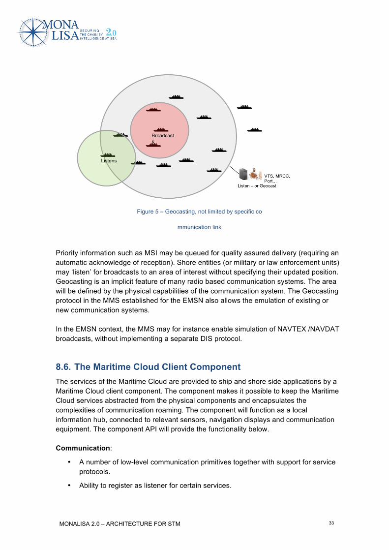
Figure 5 – Geocasting, not limited by specific co
mmunication link
Priority information such as MSI may be queued for quality assured delivery (requiring an automatic acknowledge of reception). Shore entities (or military or law enforcement units) may ‘listen’ for broadcasts to an area of interest without specifying their updated position. Geocasting is an implicit feature of many radio based communication systems. The area will be defined by the physical capabilities of the communication system. The Geocasting protocol in the MMS established for the EMSN also allows the emulation of existing or new communication systems. In the EMSN context, the MMS may for instance enable simulation of NAVTEX /NAVDAT broadcasts, without implementing a separate DIS protocol.
8.6. The Maritime Cloud Client Component The services of the Maritime Cloud are provided to ship and shore side applications by a Maritime Cloud client component. The component makes it possible to keep the Maritime Cloud services abstracted from the physical components and encapsulates the complexities of communication roaming. The component will function as a local information hub, connected to relevant sensors, navigation displays and communication equipment. The component API will provide the functionality below. Communication:
• A number of low-level communication primitives together with support for service protocols.
• Ability to register as listener for certain services.

MONALISA 2.0 – ARCHITECTURE FOR STM 34
• Seamless roaming between different available communication systems based on a user defined rule base.
• Information on available communication systems and link quality.
Security:
• Handling the digital certificates of the Maritime Cloud Public-key infrastructure
• Authenticity verification
• Integrity verification
• Encryption for full confidentiality when necessary
Service locator:
• Locate available services based on current position, route, specific provider, specific service etc.
• Registering as provider of a dynamic service. E.g. a vessel providing own position and navigational data.
• Either online or using the offline almanac.
Almanac:
• Handling and access to the offline Almanac.
These functions, and in particular the text chat service described later in this document, has a strong relationship with the concepts being developed by the recently established IEC Project Team - PT 62940 - developing a test standard for an integrated communication system. Figure 6 shows the component as a layer in the OSI model.

MONALISA 2.0 – ARCHITECTURE FOR STM 35
Figure 6
Communication primitives Generic description of the communication primitives provided by the MC component.
Method Description
ack? ← send(id, message, ttl)
Send a message to recipient with id. Delivery of the message will be attempted within a period of ttl. Acknowledgement is optional.
void ← broadcast(area, message)
Broadcast a message to a given area (range from position, circle, rectangle, polygon). No acknowledgement from receivers.
ack[] ← broadcast(area, message, timeout)
Broadcast a message to a given area (range from position, circle, rectangle, polygon). Receive acknowledgement from receivers within timeout.
message ← receive(service_id)
Receive messages pertaining to a certain service specification. The service specification is given by id and wildcard can be used. Received messages are either addressed or broadcast with an area containing the receiving actor (mobile actor).

MONALISA 2.0 – ARCHITECTURE FOR STM 36
Method Description
message ← receive(service_id, area)
Receive messages pertaining to a certain service specification in a given area. Non-mobile actors use this to receive messages for an area.
9. Systems and products to be provided in the EMSN The following systems and products have been considered relevant in the context of performing simulations in the EMSN:
9.1. STCC Transas will provide the STCC functionality.
• Voyage Plan collection database. (No dynamic Voyage number generator will be implemented initially; a static list of logged voyage plans will be part of setting up the EMSN test scenarios.)
• Communication interface (Maritime Cloud Client Component – extracted from ACCSEAS EPD implementation, and SSPA specified interface to route optimisation & deconfliction)
• VTS operator HMI application, that support presentation of routes, text chatting plus MSI&MSP data, and interactions using the Voyage Plan format with ships and Service provider for route optimisation & deconfliction
DMA will provide Transas with reference implementation of textchat and route exchange (currently par of EPD from MONALISA 1 project) Transas will provide interface specification for voyage plan exchange service using the new Voyage Plan format
9.2. PML (Shipborne Planning station with STM functionality) Transas will provide the planning station based on existing ECDIS platform.
• HMI application, that support planning and presentation of routes, MSI&MSP data plus text chatting and interactions using the Voyage Plan format with STCC and Service provider for Weather Routing
• Routes must be transferrable to EML for activation

MONALISA 2.0 – ARCHITECTURE FOR STM 37
• Communication interface (Maritime Cloud Client Component – extracted from ACCSEAS EPD implementation, and SMHI specified interface to weather routing – could act as ships communication node)
Transas will provide interface specification for voyage plan exchange service using the new Voyage Plan format
9.3. EML (Shipborne ECDIS monitoring station with STM functionality)
Transas will provide the planning station based on existing ECDIS platform.
• HMI application, that support route activation and monitoring, presentation of routes MSI&MSP data, plus text chatting and interactions using the Voyage Plan format with STCC
• Routes must be transferrable from PML for activation
• Communication interface (Maritime Cloud Client Component– could be indirectly)
Transas will provide interface specification for voyage plan exchange service using the new Voyage Plan format
9.4. Service Provider – Route optimisation (Weather) SMHI will provide the first instance of a Weather route optimisation service in the context of the EMSN, based on:
• Route optimisation service that supports Voyage plan format
• Communication interface (Maritime Cloud Client Component – extracted from ACCSEAS EPD implementation of MMS. If this is not possible in time, then SOAP interface can be used for the EMSN, while MMS service definition is being developed)
SMHI is to provide interface specification in liaison with Transas
9.5. Service Provider – (MSI) The ACCSEAS project is developing S-100 based data format descriptions and a promulgation mechanism based on the Maritime Cloud for MSI (Maritime Safety Information) and NtM T&P (Notices to Mariners, Temporary and Preliminary). This can be reused by the MONALISA 2.0 project for a quick start to describing MSI data for the

MONALISA 2.0 – ARCHITECTURE FOR STM 38
simulation scenarios, and delivering them to relevant workstations. The system will consist of:
• A frontend web application for registering MSI and NtM T&P, delivered by ACCSEAS project
• Communication interface (REST interface for requesting active MSI, MMS)
• A Maritime Cloud based Geocasting MMS service for distributing MSI and NtM T&P data – (later – pending ACCSEAS implementation)
DMA will provide service specification and reference implementation from ACCSEAS project
9.6. Service Provider – Route optimisation & deconfliction SSPA will provide the first instance of optimisation & deconfliction tool for the EMSN.
• Route optimisation & deconfliction tool that supports Voyage plan format
• Communication interface (– to be specified by SSPA in liaison with Transas)
9.7. Maritime Cloud DMA will provide and operate an EMSN instance of the most essential Central Platform Service for the Maritime Cloud: The Maritime Messaging Service (MMS), serving as the communication hub in the Maritime Cloud will be functional and will include:
• The MSS server, through which all Maritime Cloud Client Components can connect and make machine-to-machine transfer of Voyage Plans, text chat or other data, and maintain Maritime Cloud awareness of the location of all actors
• Promulgation of MSI and NtM data, exposing these data to all Maritime Cloud Client Components within relevant geographical context
The Maritime Identity Registry (MIDR) will not be finalised for the initial implementation of the EMSN, instead fixed MMSI numbers must be used, identifying all actors taking part in the interactions via the Maritime Cloud as well as simulated AIS, etc. MMSI’s must be assigned to actors at scenario planning, and the MMSI must be registered during the configuration of the Maritime Cloud Client Component at each actor. The Maritime Service Registry (MSR) will not contain any static data for the implementation of the EMSN, only services registered by Maritime Cloud Client Components at start-up will be available during runtime. DMA will provide reference implementations and documentation from the ACCSEAS project on an on-going basis, as it is being released.

MONALISA 2.0 – ARCHITECTURE FOR STM 39
10. Core services to support STM in EMSN • Dynamic Voyage planning
o In Planning phase, the Strategic Voyage Plan can be exchanged with Service Provider for weather optimisation, etc.
o When loaded in ECDIS, or if route is updated, the Dynamic Voyage Plan is automatically pushed to STCC
o STCC will store in own STM database
o STCC may request updated route to verify that they have most recent route
o STCC may exchange Dynamic Voyage Plan with Service Provider for optimisation or deconfliction
• Text chat (Apply standard maritime phrases / abbreviations)
• Tactical route (near future subset of Dynamic Voyage Plan) is broadcast ship-to-ship and ship-to-shore
• Tactical route suggestion (alternative route segment) or Flow management suggestion (alternative speed or ETA to Flow Waypoints) used to negotiate minor changes to part of the Dynamic Voyage Plan
• MSI (following international standards for NAVTEX) plus S-100 proposed format by ACCSEAS project
• MSP (Maritime Spatial Planning - format to be specified by sub activity 1.7 (or using the MSI/NtM T&P delivered by the ACCSEAS project)
10.1. Interaction diagrams for STM in the EMSN Sub-activity 1.2 of the MONALISA 2.0 project has developed a number of interaction diagrams, indicating the information flow in the desired STM interactions to be trialled, indicated in the figures below. In the following section, sequence diagrams are provided, indicating which system will interact with other systems, and in which sequence, in performing the core services¨.

MONALISA 2.0 – ARCHITECTURE FOR STM 40
Voyage planning interactions
Figure 7 - original Voyage Planning interaction diagram by sub-activity 1.2
Voyage monitoring - Ship <-> VTS/STCC interaction

MONALISA 2.0 – ARCHITECTURE FOR STM 41
Figure 8 - Original Voyage Monitoring interaction diagram by sub-activity 1.2
10.2. Sequence diagrams In this section, sequence diagrams indicating the sequence of interactions in performing the core functions are provided. (The first set of diagrams for requesting a route template explains how the diagrams are structured.) Requesting a Route Template When a ships voyage is planned from Port A to Port B, the operator of the Planning Station (PML) might load a predefined route from a local list of route templates, or request a template from at route template service. In the EMSN trials, a predefined route library in the PML could be quite sufficient, however this case is used to illustrate how a service for requesting a Route Template from an external information service provider, could be defined. This interaction is foreseen to be initiated by a planning station (on a ship) requesting a route template from a service provider, which could be the STCC or an independent Service Provider. Two examples are provided:
a) Request through the MMS
b) Request through another protocol

MONALISA 2.0 – ARCHITECTURE FOR STM 42
In figure 9, the request is passed from one system (the PML) to the local MCCC (Maritime Cloud Client Component), via the MMS (option a), to the MCCC of the STCC, where the Route Template Service is located in this example.
Figure 9 - Route Template requested via MMS - the full version
To remove the details of interacting via the MMS, figure 10 indicates the same interaction, without indicating the MMS inside the Maritime Cloud.
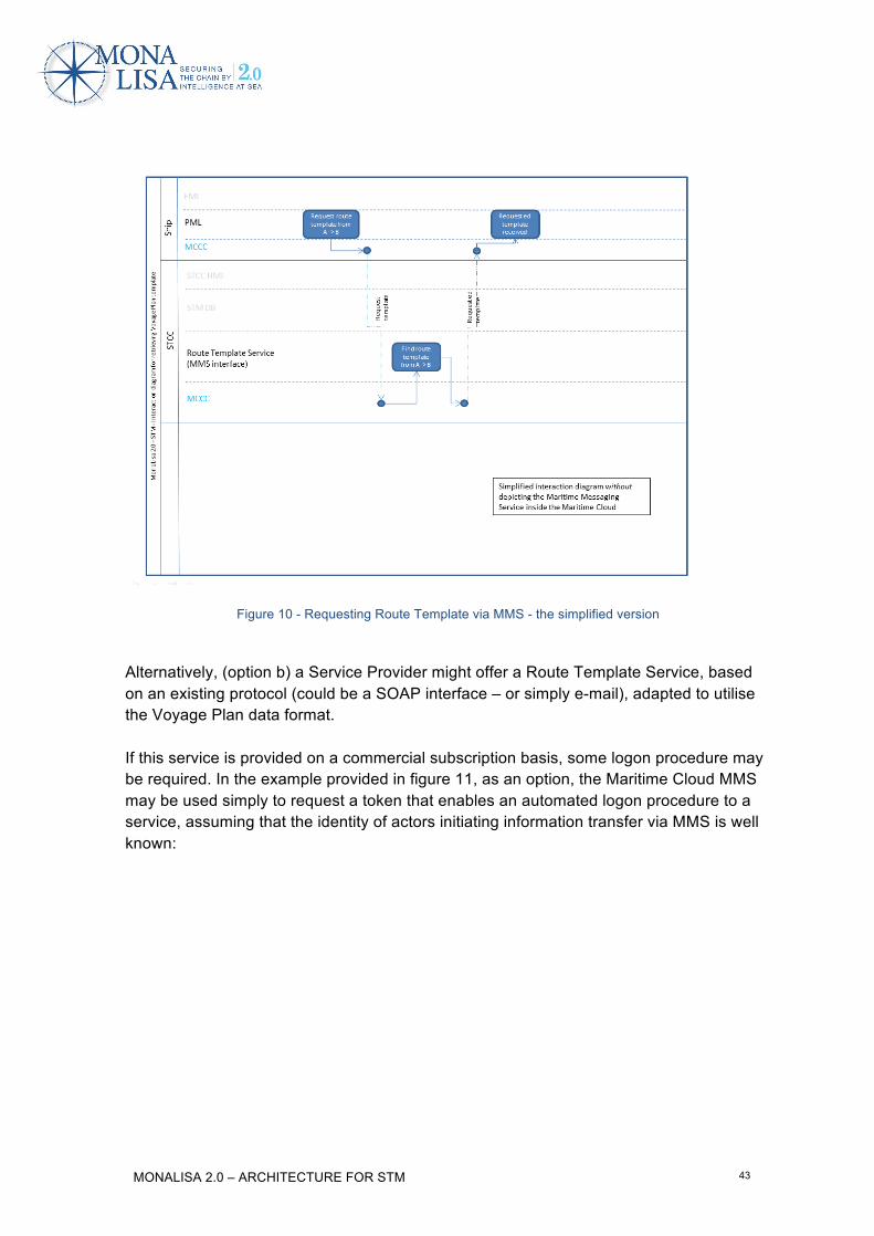
MONALISA 2.0 – ARCHITECTURE FOR STM 43
Figure 10 - Requesting Route Template via MMS - the simplified version
Alternatively, (option b) a Service Provider might offer a Route Template Service, based on an existing protocol (could be a SOAP interface – or simply e-mail), adapted to utilise the Voyage Plan data format. If this service is provided on a commercial subscription basis, some logon procedure may be required. In the example provided in figure 11, as an option, the Maritime Cloud MMS may be used simply to request a token that enables an automated logon procedure to a service, assuming that the identity of actors initiating information transfer via MMS is well known:

MONALISA 2.0 – ARCHITECTURE FOR STM 44
Figure 11 - Requesting Route Template via e.g. SOAP protocol
Regardless of which technical protocol is used for implementing the information transfer, the service description of a Route Template Service should describe the technical data transfer protocol (MMS, SOAP, or something else), the data content being transferred, and any sequential constraints. In the case of a Route Template Service, the request could be a Voyage Plan, containing only the ships static data, and two waypoints – Port A and Port B, either with NO schedule data (speed on the leg) – or a ‘normal’ or ‘desired’ speed on the leg between A and B. The response to the request will be a Voyage Plan, and its level of detail depends on the sophistication of the service provider. In a crude form, the draft Voyage Plan response may contain a set of standard waypoints enabling travel from port A to Port B without running aground, based on the ships static data, and no schedule information, or just a schedule assuming the ‘desired speed’ on all legs, resulting in a rough estimation of ETA. In this case the ship will be left to adjust the details, including the schedule, using their own intuition or optimisation systems, or sending the Voyage Plan to an external optimisation service, for optimisation to meet a desired ETA and/or meeting other requirements.

MONALISA 2.0 – ARCHITECTURE FOR STM 45
A more sophisticated service may take into account numerous other parameters, such as already known ships particulars, weather, current local restrictions, etc., etc., and providing a detailed response including a Voyage Plan with a highly detailed route and schedule, possibly including notifications to be taken into consideration at certain stages of the route.
Text chat
Text chatting is a required interaction to be used in the EML and PLM applications to communicate with STCC during STM interactions. Text chat can be implemented via AIS, and this function typically exists in an ECDIS. This will work fine in the EMSN, but in real life only for actors who have their own unique AIS station – and this does not work well for a shore based STCC, that may have access to several AIS base stations with different MMSI identities. Text chat via the MMS service in the Maritime Cloud can easily involve shore-based actors without access to own AIS station. A local ‘text service’ is envisaged, which will be able to replicate whatever has been communicated as originating from one ship between different applications or workstations at the same actor.
Figure 12 - Textchat - a simple example of information transfer via MMS, optionally AIS

MONALISA 2.0 – ARCHITECTURE FOR STM 46
Log Voyage Plan with STCC - Request STCC route verification
At planning time, a Draft Voyage Plan should be logged with the STCC when the route status changes. Upon request, the STCC may be requested to verify a Draft Voyage Plan against risk of grounding, published MSI, MSP or other data. In response, relevant MSI or MSP data will be provided, relevant to the route – and if no issues are detected, a verified Voyage Plan (Route status 4) will be returned.
Figure 13 - At planning time, draft voyage plans are logged, and may be verified by STCC
Request optimisation of Voyage Plan
During planning time, or during voyage execution, a request may be sent from either the EML or PML to request optimisation of the Voyage Plan for weather (or other parameters), from a route optimisation service.

MONALISA 2.0 – ARCHITECTURE FOR STM 47
Figure 14 - requesting weather optimisation of a Voyage Plan
Activate Voyage Plan and log with STCC When the route is approved by the Master and loaded in the ECDIS, it is automatically logged with the STCC. Any changes to the route or schedule will result in an update being sent to the STCC.

MONALISA 2.0 – ARCHITECTURE FOR STM 48
Figure 15 - During monitoring phase any updates to the Voyage Plan are sent to STCC
Broadcast or request Intended Route In order to enable ships in the EMSN to understand the intentions of other ships, two protocols are applied for exchanging ‘tactical route’. It is a bit like cars using turn signals to indicate the intention to turn left or right before the car slows down and turns. The Tactical Voyage plan will be based on the Dynamic Voyage plan. It should reflect the updated reckoning of the navigator, the actual intention for the next few hours, taking into account the discrepancy between planned and actual speed at resulting ETA at each waypoint. It should enable other navigators to inspect the intention of another ship and better estimate CPA’s. Two different protocols will be applied:
1. AIS ASM (broadcast of next few waypoints)
2. Request / response of route intention, using the Voyage Plan data format via MMS – (including the schedule information)

MONALISA 2.0 – ARCHITECTURE FOR STM 49
Figure 16 - Broadcast or request of tactical route intention
The broadcast tactical route should reflect the currently calculated actual ETAs of waypoints based on the Dynamic Voyage Plan plus current position and speed, rather than the originally planned ETA’s in the Strategic Voyage plan. As long as minor tactical deviations to the route do not exceed the allowed cross track errors in the active Dynamic Voyage plan, and the ETAs of waypoints remains insignificant, the Dynamic Voyage plan is considered intact. If the tactically planned deviations result in ETA deviations more than a certain limit (to be determined), the safety check does not need to be reconsidered, but the updated Dynamic Voyage plan could be sent to STCC, to enable recalculation of CPA effects on other stakeholders as a result of the ETA changes – e.g. to support changes in the Collaborative Decision Making process in a port environment as a result of significant ETA changes. If tactically planned deviations result in exceeding the allowed cross track errors, the safety Check of the changes to the Voyage Plan must be reconsidered, and when activated, the updated Voyage Plan must be sent to STCC. Broadcast via AIS A ship should regularly (for instance every 5 minutes) broadcast the latest Tactical route (the route for the next few hours) via AIS ASM (Application Specific Message - IMO SN.Circ/289, DAC=001, FI=27, route type=5). The specification is provided in ANNEX B.

MONALISA 2.0 – ARCHITECTURE FOR STM 50
This format will allow the broadcast of up to 8 waypoints, however contains no detailed schedule information. This data format does not; however specify the turning radius at waypoints, which introduces significant uncertainty in predicting the actual path at a turning point. In order to assist estimation of CPA/TCPA, schedule information is vital and it would be recommendable to develop and test a proposal for an alternative ASM format better suited to support STM. The existing ASM format may carry 16 waypoints (using 5 timeslots on the AIS radio link), however a maximum of 8 waypoints (using 3 timeslots) is recommended, otherwise the data transfer is at risk of being garbled, and the saturation of the AIS system is at risk. If the EMSN trials prove this service to be useful, then instead of making this broadcast exclusively part of the existing AIS, the broadcast should be alternated between the AIS and the new ASM frequencies introduced as part of VDES (VHF Data Exchange System). This way, ships carrying legacy AIS systems will receive the broadcast infrequently, while ships with new VDES systems will receive the broadcast frequently. (The ASM data format could in this case be redesigned, providing room for more waypoints as well as schedule information, as the bandwidth on the new frequencies is expected to be higher.) The current ASM format cannot indicate intended speed on the legs between waypoints or ETA of waypoints. Hence, any calculation of CPA / TCPA based on this broadcast, has to be made with the assumption of constant speed. The format describes a Start Date and Time and a Duration. The meaning of the start timestamp and duration (‘minutes until end of validity’) are not really well defined, but for the trials in the EMSN, the following will be used: Start Date and Time: The time at which first waypoint in the ASM package was passed. Duration: The number of minutes from Start Date and Time until currently calculated ETA of the last waypoint.

MONALISA 2.0 – ARCHITECTURE FOR STM 51
Figure 17 – broadcast of next few waypoints / hours. AIS broadcast only contains geometry of waypoints, time of first waypoint, and estimated duration until last waypoint. The STM Voyageplan format can contain a longer
route segment including the schedule.
Request / response via MMS Via the Maritime Cloud, the STCC or another ship may request a ship’s Tactical Voyage plan, and the response will contain the tactical route, using the STM Voyage plan data format, including route geometry and schedule for the next five hours (or a configurable time window). More waypoints can be included than the AIS ASM, and more importantly the schedule (speed on legs and ETA of waypoints) can be provided, enabling more detailed estimation of CPA / TCPA between ships over a longer timespan, etc.
Tactical Route negotiation
If the STCC determines the need to change the layout of a route, a proposed route segment is sent to a ship, and the ship may accept or deny the proposal. If the proposal only involves a speed / ETA change, the proposal can immediately be accepted or rejected by the ship. If the route layout is changed, the proposed alternative must be safety checked, before it is accepted or rejected.

MONALISA 2.0 – ARCHITECTURE FOR STM 52
Figure 18 - STCC sends route suggestion to ship
Figure 19 - The interaction is handled by the STCC sending the proposed route segment to the ship via the MMS.

MONALISA 2.0 – ARCHITECTURE FOR STM 53
If the route proposal is accepted, the broadcast Tactical route should immediately be adjusted accordingly, so all ships in the area can then see the updated intention of ship A.
Figure 20 - if ship accepts route proposal, tactical route broadcast should automatically be adjusted, so other ships can see the updated intention of the ship
MSI – Maritime Safety Information
In order to establish an MSI service in the EMSN, the implementation of a MSI service from the ACCSEAS project will be reused. This service includes a HMI for registering MSI (Maritime Safety Information) and NtM T&P (Temporary and Preliminary Notices to Mariners), based on proposals for S-100 based data models.

MONALISA 2.0 – ARCHITECTURE FOR STM 54
Figure 21 - MSI broadcast
DMA will deliver and publish data model- and interface descriptions as soon as they are available from the ACCSEAS project.
MSP – Marine Spatial Planning
No specification of the data format or of an MSP data service exist at the time this document was written. It is however expected that the nature of MSP data will resemble Temporary or Preliminary NtM (Notice to Mariners), and thus, potentially, the MSI / NtM service can be used to enable importing and publishing MSP data in the EMSN.
MONALISA 2.0 – ARCHITECTURE FOR STM 55
Annex A – MONALISA Route Exchange format
On the 19th of August 2015, IEC adopted edition 4 of the 61174 standard, where Annex S contains a route exchange format. This standardised route exchange format primarily builds on the work in the MONALISA 2.0 project and is divided into three major blocks • Route General Information • Route Geometry block • Route Schedule block
Each block can contain mandatory and optional information It should also be possible for manufacturer to add own container of information. DISCLAIMER This proposal may differ in some parts from the standard that was later published by IEC. The format described here below MUST NOT be used for any implementation of the standard. Please refer to www.iec.ch to obtain the IEC 61174 ed. 4 documentation. Note: There are known implementation issues at the time of publishing: Namespace definitions in this proposal do not match the IEC standard, and the naming of “sheduleElement” / “scheduleElement” has been noted as inconsistent.
The route exchange format as proposed to IEC This section contains the proposal for the route exchange format as it was delivered from the MONALISA 2.0 project to IEC.
A.1 General
This route plan exchange format is intended to be used for many purposes. For example it can be used on board for route plan exchange between main and backup ECDIS, ECDIS and radar, ECDIS and optimisation systems, etc. Another example of use is between ship and shore where it can be used to inform the shore about the plan of the vessel, the shore can recommend a route, the shore can optimise a route, etc. This route plan exchange format, is based on standardising a single route plan. The application level of the sender and receiver is assumed to be able to handle multiple route plans for use cases that require availability of multiple routes, for example alternative route plans for the same voyage or route plans for different purposes. A route plan consists of waypoints. Each waypoint contains information related to the leg from the previous waypoint. Descriptions of route plans are shown in Figures A.1 and A.2. The route exchange format is a file containing an XML coded version of the route plan. The XML route exchange file uses the extension .rtz. A description of the RTZ format is given in Clause A.5. Examples of RTZ format routes are given in Clauses A.7 and A.8.
Clause A.6 gives an XML schema to be met by RTZ route files so that their structure and content can be verified.

MONALISA 2.0 – ARCHITECTURE FOR STM 56
NOTE 1: This route exchange format has some limitations for applicability due to the simple geometric mode used. Application for latitudes above 70º may cause significantly different paths over the earth surface between two systems. Application to long legs such as an ocean crossing is subject to differences in the exact path over the earth surface.
NOTE 2: It is recommended that the receiver of the route exchange always performs a check against the chart database and a geometry check before use for navigation purposes.
NOTE 3: Information in addition to the route exchange format will be necessary between third parties to assure the level of accuracy and repeatability required for Track Control System purposes.
WP2(geographicalcoordinates)
Radius
WP
GM_PointGeographicalCoordinates
4
Radii
WP1(geographicalcoordinates)
WP3(geographicalcoordinates)
Calculateddistance
NOTE: The distance between waypoints is from WOL to WOL with zero “advance and transfer” or “forwarding distance”.
Figure A.1 – Description of route plan – distance between WP 2 and WP 3
Figure A.2 – Description of route plan – leg parameters belonging to WP 3
PROPOSAL–must
notbeusedfor
implementation

MONALISA 2.0 – ARCHITECTURE FOR STM 57
A.2 RTP Data container
Data containers are standard ZIP archive files used to compress the size of the route exchange files. The container file .rtzp stores a XML file .rtz, which conforms to the XML schema described in Clause A.6. Use of the data container is optional with removable media. In this case the route exchange may be used with or without the data container. When used without the data container the filename of the route exchange is .rtz instead of .rtzp.
NOTE: The filename is the attribute routeName described in A.5.3. In addition to the .rtz file a number of free-format files may be placed in the data container. The semantic data link between the XML nodes and files may be documented using a HTTP like scheme "rtz://<URI>", where "<URI>" identifies a file name inside the data container. For example: <extensions>
<extension manufacturer="Acme" version="2.1"
name="AuxRouteInfo-9674F26E-EAFB-4319-AE24-08D5BA69D895">
<property name="source"
value="http://services.acme.com/auto_route/?id=3e891884e620970e5303fd2399427986"/>
<property name="attachment" value="rtz://assignement-13.04.2013.docx"/>
<property name="attachment" value="rtz://MFD_original.rt3"/>
</extension>
</extensions>
<extensions>
A.3 High-level description of the RTZ format
The logical design of a route consists of three independent units:
• A block with general information about the route; • A block with route geography (geometry) information that consists of blocks
describing individual legs. Legs are listed in the order they appear on the route; • A block that contains a set of route schedules. Each block can be extended by manufacturers to fit their needs.
A.4 Adaptation to third-party extensions
A.4.1 Generic idea
Extended information in most cases refers to the geography (geometry) of a route. There is a need to ensure that:
• for the possibility to keep extensions from different manufacturers in a single file;
• that modifying the geography (geometry) of a route shall not result in extensions data bindings being invalid;
PROPOSAL–must
notbeusedfor
implementation

MONALISA 2.0 – ARCHITECTURE FOR STM 58
• that when changing, adding or removing legs, data consistency should not break down due to unknown extensions in codes for a particular manufacturer.
A.4.2 Unique identification of a waypoint
Each waypoint in a route has a unique composite ID.
It is assumed that all RTZ extensions use this identifier to link their data to the geography. The identifier consists of two parts:
• ID, which allows the finding of a waypoint in the list; • Revision, which allows the determination of modifications of a waypoint since the
entry of the data into a file extension. ID is an integer
Revision is a monotonically increasing integer. A.4.3 Creation of new waypoints
After creation of the waypoint the revision attribute gets the value of 0. A.4.4 Change of geographic data for a waypoint
When the data of a waypoint changes, the software should increase the revision number revision, so that third-party software that works with the extension, is able to find out that the data to which it is associated is no longer valid. A.4.5 Waypoint removal
When deleting a waypoint from a route, all the waypoint data including schedule data is deleted and the waypoint numbers within the route are updated. Responsibility for the extension's data modification is assigned to the manufacturer’s code only. The data that software is not able to recognise (e.g. extensions and options) are written back into the modified file without modification. It is assumed that the receiver which understands extensions is able to filter out data when reading the route and be able to eliminate the data of extensions related to removed or to non-existent waypoints.
A.5 Detailed RTZ format description
A.5.1 File components
The RTZ file consists of:
• the mandatory XML processing instruction, which allows the specification of the encoding of string data;
PROPOSAL–must
notbeusedfor
implementation

MONALISA 2.0 – ARCHITECTURE FOR STM 59
• a root <route> node, which includes the URIs of the standard namespace http://www.w3.org/2001/XMLSchema-instance as well as the RTZ namespace6 http://www.cirm.org/RTZ/1/0;
• the version attribute in the format "Major.Minor" (currently "1.0").
The preferred file encoding is UTF-8. A.5.2 Route node description
This is the only "root" element of the RTZ file.
It has one mandatory attribute "version" that contains the version of the RTZ format used during file creation.
Version is specified as a combination of two figures separated with a dot. The first figure corresponds to the major version. It shall be changed in the case of significant modifications to the document structure. Formats with different major versions are incompatible.
The second figure corresponds to the minor version and indicates format changes that do not affect compatibility.
The Route node consists of a sequence of the following child nodes:
• RouteInfo node that contains basic information on the route;
• Waypoints node that describes the geographical components of the route;
• Schedules node that describes calculated schedule and timing defined by a user;
• Extensions node that allows for extending the format to fit the particular needs of a manufacturer.
A.5.3 RouteInfo node description
The RouteInfo node provides a place to store information related to the whole route.
Information is stored in the following attributes:
Attribute Description Format Status Comment
routeName name of the route String Mandatory
routeAuthor Author of route String Option
routeStatus Status of route String Option
validityPeriodStart Start of validity period ISO 8601 Option
validityPeriodStop Stop of validity period ISO 8601
Option
vesselName Ship’s name String Option
vesselMMSI Ship’s MMSI XXXXXXXXX Option
6 Comité International Radio-Maritime (CIRM) is the international association for marine electronics companies.
PROPOSAL–must
notbeusedfor
implementation

MONALISA 2.0 – ARCHITECTURE FOR STM 60
Attribute Description Format Status Comment
vesselIMO Ship’s IMO number XXXXXXX Option
vesselVoyage Number of the voyage String Option
vesselDisplacement Ship’s displacement Integer Option Unit: tons
vesselCargo Ship’s cargo Integer Option Unit: tons
vesselGM Metacentric height
XX.XX Option Metacentric height of the ship for intended voyage. Unit: metres
optimisationMethod Route is optimised to meet KPI
String Option Could be fixed speed, Lowest Fuel Consumption, Fixed ETA
vesselMaxRoll Ship’s max roll angle allowed
XX Option Unit: degrees
vesselMaxWave Ship significant wave height limit
XX.X Option Unit: metres
vesselMax_Wind Ship’s max wind speed limit
XX.X Option Unit: metres
vesselSpeedMax Ship’s max speed XX.X Option Unit: knots, Speed through water
vesselServiceMin Ship’s preferred service speed window_min
XX.X Option Unit: knots, Speed through water
vesselServiceMax Ship’s preferred service speed window_max
XX.X Option Unit: knots, Speed through water
routeChangesHistory Cause of route change, Originator and Reason
String Option
For example: <RouteInfo routeName="AROUNDtheSKAGEN" /> vesselName=”ACME” validityPeriodStart=”2014-01-03T03:15:00Z” validityPeriodStop=”2014-01-06T10:15:00Z” vesselMMSI=”xxxxxxxxx”
vesselVoyage =”xxxx”/>
Additionally, the node may contain a child extension. A.5.4 Waypoints node description
The Waypoints node contains data related to the geometry of the route. As minimum, it shall contain a sequence of Waypoint nodes that describe every leg of the route. The order of the Waypoint nodes follows the order of the legs.
Before the sequence of Waypoint nodes it is possible to insert a DefaultWaypoint node, which defines default values of attributes for newly created legs except for the geometry data. For example:
PROPOSAL–must
notbeusedfor
implementation

MONALISA 2.0 – ARCHITECTURE FOR STM 61
<Waypoint id="24" revision="3" radius="0.6">
<Position lat="53.0513" lon="8.87509"/>
<Leg starboardXTD="0.2" portsizeXTD="0.1" geometryType="1"/>
</Waypoint>
Additionally, the node may contain a child extensions node. A.5.5 DefaultWaypoint node description
The DefaultWaypoint node allows the definition of default values of attributes for newly created waypoints.
For example: <Waypoints>
<DefaultWaypoint radius="1.4">
<Leg starboardXTD="0.5" portsizeXTD="0.5" geometryType="0"/>
</DefaultWaypoint>
If the DefaultWaypoint node is provided before the sequence of waypoints, then it shall contain values for attributes for newly created waypoints. For example: <Waypoints>
<DefaultWaypoint radius="1.4">
<Leg starboardXTD="0.3" portsideXTD="0.3"
geometryType="0"/>
</DefaultWaypoint>
Defaults settings for all waypoints
<Waypoint id="33" rev="1"/>
<Position lat="53.0492" lon="8.87731"/>
</Waypoint>
For this waypoint default settings applied
<Waypoint id="17" rev="3" radius="0.3">
<Position lat="53.0513" lon="8.87509"/>
<Leg starboardXTD="0.4" portsideXTD="0.5"
geometryType="1"/>
</Waypoint>
For this waypoint user settings applied: Port XTD = 0,5 NM Starboard XTD = 0,4 NM Turn radius = 0,3 NM Geometry type is orthodrome
A.5.6 Waypoint node description
The Waypoint node contains the geographical description of a leg between waypoints.
Information is stored in the following attributes:
Attribute Description Format Status Comment
id Unique identifier Integer Mandatory It does not have to be equal to the index of the waypoint
revision Waypoint revision Integer Option Index of revision
name Waypoint String Option
radius Turn radius Real Option Unit: NM
position Geographic point GM_Point Mandatory Unit: degrees
leg Leg attributes
Mandatory Optional for the first waypoint
PROPOSAL–must
notbeusedfor
implementation

MONALISA 2.0 – ARCHITECTURE FOR STM 62
Position node contains the latitude and longitude of the waypoint.
Attribute Description Format Status Comment
lat Latitude Real Mandatory Unit: degrees with decimal
lon Longitude Real Mandatory Unit: degrees with decimal
Leg node contains attributes of the leg associated with the waypoint (see Figure 5.2).
Attribute Description Format Status Comment
starboardXTD Starboard XTD Real Option Unit: NM with decimal
portsideXTD Portside XTD Real Option Unit: NM with decimal
safetyContour Planned Safety contour Real Option Unit: metres
safetyDepth Planned Safety depth Real Option Unit: metres
geometryType Geometry type of leg Enumeration Option
loxodrome (= rhumb line) or orthodrome (= great circle)
planSpeedMin Lowest cruising speed Real Option Unit: knots, Speed over ground
planSpeedMax Highest allowed speed Real Option Unit: knots, Speed over ground
draughtForward Static Draught Forward Real Option Unit: metres
draughtAft Static Draught Aft Real Option Unit: metres
staticUKC Minimum UKC on the leg Real Option Unit: metres
dynamicUKC Minimum Dynamic UKC on the leg Real Option Unit: metres
masthead Height of masthead Real Option Unit: metres Calculated from keel
legReport Reporting information String Option Part of annotated route plan
legInfo Nice to know String Option
e.g. telephone / web / service point Could be relevant in approach to harbour or VTS
legNote1 Notes regarding the ETD/ETA String Option
legNote2 Local remarks String Option
If an optional attribute is absent the appropriate parameter will be taken from the element defaults node. If this parameter is absent in the defaults node, then its value is set to
PROPOSAL–must
notbeusedfor
implementation

MONALISA 2.0 – ARCHITECTURE FOR STM 63
"zero" or "empty", depending on the type of the parameter. For the case when geometryType is absent, this attribute should be considered as “Loxodrome”. Additionally, the node may contain a child extensions node. A.5.7 Storing date and time for legs
Date and time parameters that are associated with the corresponding legs are stored as strings of calendar date and UTC in extended format according to ISO 8601.
For example: <Schedule id="2" name="Schedule2">
<Manual>
<ScheduleElement id="100" etd="2002-11-17T15:25:00Z"/>
<ScheduleElement id="105" eta="2002-11-17T15:25:00Z"/>
</Manual>
</Schedule>
A.5.8 Schedules node description
The Schedules node contains data on the schedules associated with the route. Children schedule nodes describe the specific schedule.
Additionally, the node may contain a child extensions node. A.5.9 Schedule node description Components
schedule node consists of a sequence of the following child nodes:
• Manual node that describes user's preferences for the schedule;
• Calculated node that describes schedule calculation results according to user's preferences.
Additionally, the node may contain a child extensions node. Manual node description
Manual node contains a sequence of ScheduleElement nodes that describe time preferences and calculation restrictions for each leg of the route. A waypoint should not have more than one associated ScheduleElement within a Manual node. Additionally, the node may contain a child extensions node. Calculated node description
Calculated node contains a sequence of ScheduleElement nodes that store calculations results according to user's preferences. A waypoint should not have more than one associated ScheduleElement within a Calculated node. Additionally, the node may contain a child extensions node. ScheduleElement (manual/calculated) node description ScheduleElement node stores a number of time-oriented values related to the route leg (N-1, N), where N is a zero-based index of the leg in the list.
Information is stored in the following attributes:
PROPOSAL–must
notbeusedfor
implementation

MONALISA 2.0 – ARCHITECTURE FOR STM 64
Attribute Description Format Status Comment
waypointID Identifier of waypoint Integer Mandatory
etd Departure time ISO 8601 Option
etdWindowBefore
Describes the uncertainty of the predicted etd after optimisation
+ HH.MM Option
- HHMM to etd
etdWindowAfter
Describes the uncertainty of the predicted etd after optimisation
+ HH.MM Option + HHMM after etd
eta Arrival time ISO 8601 Option
etaWindowBefore Describes the uncertainty of the predicted eta after optimisation
+ HH.MM Option - HHMM to eta
etaWindowAfter Describes the uncertainty of the predicted eta after optimisation
+ HH.MM Option + HHMM after eta
stay Stay time on WP dd.hh.mm Option Length of stop on WP
speed Ground speed Real Option Unit: knots
speedWindow Describes the uncertainty of the predicted speed after optimisation
+ x.xx Option
Unit: knots - x.xx knots to + x.xx knots
windSpeed True wind speed Real Option Unit: knots
windDirection True wind direction Real Option Unit: degrees
currentSpeed Current speed Real Option Unit: knots
currentDirection Current direction Real Option Unit: degrees
windLoss Speed loss caused by wind Real Option
Unit: knots Calculated during optimisation
waveLoss Speed loss caused by wave Real Option
Unit: knots Calculated during optimisation
totalLoss Total speed loss Real Option Unit: knots Calculated during optimisation
rpm Advised Engine RPM Integer Option Unit: RPM Calculated during optimisation
pitch Advised propeller pitch Integer Option Unit: % Calculated during optimisation
fuel Predicted fuel consumption on leg Real Option
Unit: kg Calculated during optimisation
PROPOSAL–must
notbeusedfor
implementation

MONALISA 2.0 – ARCHITECTURE FOR STM 65
Attribute Description Format Status Comment
relFuelSave Relative fuel saving after optimisation Real Option
Unit: kg Calculated during optimisation
absFuelSave Absolute fuel saving after optimisation Real Option
Unit: kg Calculated during optimisation
Note
String Option
For example: <Schedule id="2" name="Schedule2">
<Manual>
<SheduleElement id="100" etd="2002-11-17T15:25:00Z" />
<SheduleElement id="105" eta="2002-12-17T15:25: 00Z" />
</Manual>
<Calculated>
<SheduleElement id="100" etd="2002-11-17T15:25:00Z” speed="11.00000000"/>
<SheduleElement id="105" eta="2002-12-17T15:25:00Z" speed="12.23242000"/>
</Calculated>
<Extensions>
</Extensions>
</Schedule>
Additionally, the node may contain a child extensions node. A.5.10 Extensions node description
The Extensions node contains a set of child extension nodes, each of which specifies additional information that may be associated with:
• whole route;
• whole geographical data;
• certain waypoint;
• whole schedules block;
• certain schedule;
• certain schedule element.
A.5.11 Extension node description
Extension node contains a set of mandatory attributes that identify the extension and a number of child nodes that may contain arbitrary information. Format of these nodes is beyond the scope of this standard. If provided, the manufacturer shall include the specification of his extension nodes in the user manual. The following attributes are used:
Attribute Description Format Status Comment
PROPOSAL–must
notbeusedfor
implementation
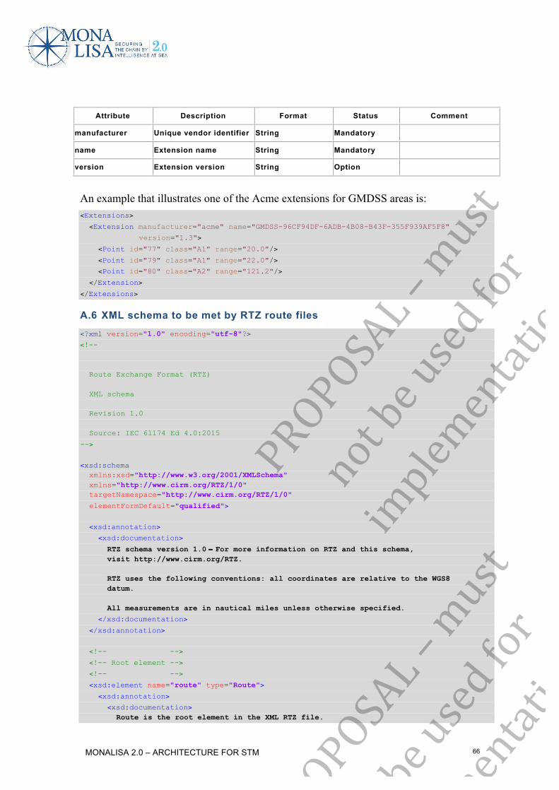
MONALISA 2.0 – ARCHITECTURE FOR STM 66
Attribute Description Format Status Comment
manufacturer Unique vendor identifier String Mandatory
name Extension name String Mandatory
version Extension version String Option
An example that illustrates one of the Acme extensions for GMDSS areas is: <Extensions>
<Extension manufacturer="acme" name="GMDSS-96CF94DF-6ADB-4B08-B43F-355F939AF5F8"
version="1.3">
<Point id="77" class="A1" range="20.0"/>
<Point id="79" class="A1" range="22.0"/>
<Point id="80" class="A2" range="121.2"/>
</Extension>
</Extensions>
A.6 XML schema to be met by RTZ route files <?xml version="1.0" encoding="utf-8"?>
<!-- Route Exchange Format (RTZ) XML schema Revision 1.0 Source: IEC 61174 Ed 4.0:2015
-->
<xsd:schema xmlns:xsd="http://www.w3.org/2001/XMLSchema" xmlns="http://www.cirm.org/RTZ/1/0" targetNamespace="http://www.cirm.org/RTZ/1/0"
elementFormDefault="qualified">
<xsd:annotation>
<xsd:documentation>
RTZ schema version 1.0 − For more information on RTZ and this schema, visit http://www.cirm.org/RTZ. RTZ uses the following conventions: all coordinates are relative to the WGS8 datum. All measurements are in nautical miles unless otherwise specified.
</xsd:documentation>
</xsd:annotation>
<!-- -->
<!-- Root element -->
<!-- -->
<xsd:element name="route" type="Route">
<xsd:annotation>
<xsd:documentation> Route is the root element in the XML RTZ file.
PROPOSAL–must
notbeusedfor
implementation
PROPOSAL–must
notbeusedfor
implementation

MONALISA 2.0 – ARCHITECTURE FOR STM 67
</xsd:documentation>
</xsd:annotation>
</xsd:element>
<!-- -->
<!-- Root element type definition -->
<!-- -->
<xsd:complexType name="Route">
<xsd:annotation>
<xsd:documentation> RTZ files contain a number of waypoints, followed with auxiliary schedules. You can add your own elements to the extension section of the RTZ document.
</xsd:documentation>
</xsd:annotation>
<xsd:sequence>
<xsd:element name="routeInfo" type="RouteInfo" minOccurs="1" maxOccurs="1">
<xsd:annotation>
<xsd:documentation> Generic route information.
</xsd:documentation>
</xsd:annotation>
</xsd:element>
<xsd:element name="waypoints" type="Waypoints" minOccurs="1" maxOccurs="1">
<xsd:annotation>
<xsd:documentation> A list of waypoints.
</xsd:documentation>
</xsd:annotation>
</xsd:element>
<xsd:element name="schedules" type="Schedules" minOccurs="0" maxOccurs="1">
<xsd:annotation>
<xsd:documentation> Optional list of schedules.
</xsd:documentation>
</xsd:annotation>
</xsd:element>
<xsd:element name="extensions" type="Extensions" minOccurs="0" maxOccurs="1">
<xsd:annotation>
<xsd:documentation> You can add extend RTZ by adding your own elements from another schema here.
</xsd:documentation>
</xsd:annotation>
</xsd:element>
</xsd:sequence>
<xsd:attribute name="version" type="xsd:string" use="required" fixed="1.0">
<xsd:annotation>
<xsd:documentation> Format version (currently "1.0").
</xsd:documentation>
</xsd:annotation>
</xsd:attribute>
</xsd:complexType>
<!-- -->
<!-- "RouteInfo" element type definition -->
PROPOSAL–must
notbeusedfor
implementation
PROPOSAL–must
notbeusedfor
implementation

MONALISA 2.0 – ARCHITECTURE FOR STM 68
<!-- -->
<xsd:complexType name="RouteInfo">
<xsd:sequence>
<xsd:element name="extensions" type="Extensions" minOccurs="0" maxOccurs="1">
<xsd:annotation>
<xsd:documentation> You can add extend RTZ by adding your own elements from another schema here. </xsd:documentation>
</xsd:annotation>
</xsd:element>
</xsd:sequence>
<xsd:attribute name="routeName" type="xsd:string" use="required">
<xsd:annotation>
<xsd:documentation>The name of the route.</xsd:documentation>
</xsd:annotation>
</xsd:attribute>
<xsd:attribute name="routeAuthor" type="xsd:string">
<xsd:annotation>
<xsd:documentation>The author of route.</xsd:documentation>
</xsd:annotation>
</xsd:attribute>
<xsd:attribute name="routeStatus" type="xsd:string">
<xsd:annotation>
<xsd:documentation>Status of route.</xsd:documentation>
</xsd:annotation>
</xsd:attribute>
<xsd:attribute name="validityPeriodStart" type="xsd:dateTime">
<xsd:annotation>
<xsd:documentation> Start of validity period in ISO 8601 format.
</xsd:documentation>
</xsd:annotation>
</xsd:attribute>
<xsd:attribute name="validityPeriodStop" type="xsd:dateTime">
<xsd:annotation>
<xsd:documentation> Stop of validity period in ISO 8601 format.
</xsd:documentation>
</xsd:annotation>
</xsd:attribute>
<xsd:attribute name="vesselName" type="xsd:string">
<xsd:annotation>
<xsd:documentation>The name of ship.</xsd:documentation>
</xsd:annotation>
</xsd:attribute>
<xsd:attribute name="vesselMMSI" type="xsd:nonNegativeInteger">
<xsd:annotation>
<xsd:documentation>MMSI of ship.</xsd:documentation>
</xsd:annotation>
</xsd:attribute>
<xsd:attribute name="vesselIMO" type="xsd:nonNegativeInteger">
<xsd:annotation>
<xsd:documentation>IMO number of ship.</xsd:documentation>
</xsd:annotation>
PROPOSAL–must
notbeusedfor
implementation

MONALISA 2.0 – ARCHITECTURE FOR STM 69
</xsd:attribute>
<xsd:attribute name="vesselVoyage" type="xsd:string">
<xsd:annotation>
<xsd:documentation>Number of the voyage.</xsd:documentation>
</xsd:annotation>
</xsd:attribute>
<xsd:attribute name="vesselDisplacement" type="xsd:nonNegativeInteger">
<xsd:annotation>
<xsd:documentation>Displacement of ship in tons.</xsd:documentation>
</xsd:annotation>
</xsd:attribute>
<xsd:attribute name="vesselCargo" type="xsd:nonNegativeInteger">
<xsd:annotation>
<xsd:documentation>Cargo of ship in tons.</xsd:documentation>
</xsd:annotation>
</xsd:attribute>
<xsd:attribute name="vesselGM" type="LengthType">
<xsd:annotation>
<xsd:documentation>Metacentric height in metres.</xsd:documentation>
</xsd:annotation>
</xsd:attribute>
<xsd:attribute name="optimisationMethod" type="xsd:string">
<xsd:annotation>
<xsd:documentation>Route is optimised to meet KPI.</xsd:documentation>
</xsd:annotation>
</xsd:attribute>
<xsd:attribute name="vesselMaxRoll" type="xsd:nonNegativeInteger">
<xsd:annotation>
<xsd:documentation> Max roll angle of ship allowed in degrees.
</xsd:documentation>
</xsd:annotation>
</xsd:attribute>
<xsd:attribute name="vesselMaxWave" type="LengthType">
<xsd:annotation>
<xsd:documentation> Ship significant wave height limit in metres.
</xsd:documentation>
</xsd:annotation>
</xsd:attribute>
<xsd:attribute name="vesselMaxWind" type="xsd:decimal">
<xsd:annotation>
<xsd:documentation> Max wind speed limit of ship in metres per second.
</xsd:documentation>
</xsd:annotation>
</xsd:attribute>
<xsd:attribute name="vesselSpeedMax" type="SpeedType">
<xsd:annotation>
<xsd:documentation>Max speed of ship in knots.</xsd:documentation>
</xsd:annotation>
</xsd:attribute>
<xsd:attribute name="vesselServiceMin" type="SpeedType">
<xsd:annotation>
<xsd:documentation>
PROPOSAL–must
notbeusedfor
implementation
PROPOSAL–must
notbeusedfor
implementation

MONALISA 2.0 – ARCHITECTURE FOR STM 70
Preferred service speed window minimum in knots.
</xsd:documentation>
</xsd:annotation>
</xsd:attribute>
<xsd:attribute name="vesselServiceMax" type="SpeedType">
<xsd:annotation>
<xsd:documentation> Preferred service speed window maximum in knots.
</xsd:documentation>
</xsd:annotation>
</xsd:attribute>
<xsd:attribute name="routeChangesHistory" type="SpeedType">
<xsd:annotation>
<xsd:documentation> Cause of route change, originator and reason.
</xsd:documentation>
</xsd:annotation>
</xsd:attribute>
</xsd:complexType>
<!-- -->
<!-- "LengthType" element type definition -->
<!-- -->
<xsd:simpleType name="LengthType">
<xsd:annotation>
<xsd:documentation>Length type.</xsd:documentation>
</xsd:annotation>
<xsd:restriction base="xsd:decimal">
<xsd:minInclusive value="0.0"/>
</xsd:restriction>
</xsd:simpleType>
<!-- -->
<!-- "SpeedType" element type definition -->
<!-- -->
<xsd:simpleType name="SpeedType">
<xsd:annotation>
<xsd:documentation>Speed type.</xsd:documentation>
</xsd:annotation>
<xsd:restriction base="xsd:decimal">
<xsd:minInclusive value="0.0"/>
</xsd:restriction>
</xsd:simpleType>
<!-- -->
<!-- Extension point type definition -->
<!-- -->
<xsd:complexType name="Extensions">
<xsd:annotation>
<xsd:documentation> You can add extend GPX by adding your own elements from another schema here.
</xsd:documentation>
</xsd:annotation>
<xsd:sequence>
<xsd:any namespace="##any" processContents="skip"
minOccurs="0" maxOccurs="unbounded">
PROPOSAL–must
notbeusedfor
implementation
PROPOSAL–must
notbeusedfor
implementation

MONALISA 2.0 – ARCHITECTURE FOR STM 71
<xsd:annotation>
<xsd:documentation> You can add extend GPX by adding your own elements from another schema here.
</xsd:documentation>
</xsd:annotation>
</xsd:any>
</xsd:sequence>
</xsd:complexType>
<!-- -->
<!-- "Waypoints" element type definition -->
<!-- -->
<xsd:complexType name="Waypoints">
<xsd:sequence>
<xsd:element name="defaultWaypoint" type="DefaultWaypoint" minOccurs="0"
maxOccurs="1">
<xsd:annotation>
<xsd:documentation>Waypoint defaults.</xsd:documentation>
</xsd:annotation>
</xsd:element>
<xsd:element name="waypoint" type="Waypoint" minOccurs="2"maxOccurs="unbounded">
<xsd:annotation>
<xsd:documentation>Waypoint details.</xsd:documentation>
</xsd:annotation>
</xsd:element>
<xsd:element name="extensions" type="Extensions" minOccurs="0" maxOccurs="1">
<xsd:annotation>
<xsd:documentation> You can add extend RTZ by adding your own elements from another schema here.
</xsd:documentation>
</xsd:annotation>
</xsd:element>
</xsd:sequence>
</xsd:complexType>
<!-- -->
<!-- "DefaultWaypoint" element type definition -->
<!-- -->
<xsd:complexType name="DefaultWaypoint">
<xsd:sequence>
<xsd:element name="leg" type="Leg" minOccurs="0" maxOccurs="1">
<xsd:annotation>
<xsd:documentation>Leg attributes.</xsd:documentation>
</xsd:annotation>
</xsd:element>
<xsd:element name="extensions" type="Extensions" minOccurs="0" maxOccurs="1">
<xsd:annotation>
<xsd:documentation> You can add extend RTZ by adding your own elements from another schema here.
</xsd:documentation>
</xsd:annotation>
</xsd:element>
</xsd:sequence>
PROPOSAL–must
notbeusedfor
implementation
PROPOSAL–must
notbeusedfor

MONALISA 2.0 – ARCHITECTURE FOR STM 72
<xsd:attribute name="radius" type="RadiusType">
<xsd:annotation>
<xsd:documentation>Turn radius in NM.</xsd:documentation>
</xsd:annotation>
</xsd:attribute>
</xsd:complexType>
<!-- -->
<!-- "RadiusType" element type definition -->
<!-- -->
<xsd:simpleType name="RadiusType">
<xsd:annotation>
<xsd:documentation>Radius type.</xsd:documentation>
</xsd:annotation>
<xsd:restriction base="xsd:decimal">
<xsd:minInclusive value="0.0"/>
<xsd:maxExclusive value="10.0"/>
</xsd:restriction>
</xsd:simpleType>
<!-- -->
<!-- "Waypoint" element type definition -->
<!-- -->
<xsd:complexType name="Waypoint">
<xsd:sequence>
<xsd:element name="position" type="GM_Point" minOccurs="1" maxOccurs="1">
<xsd:annotation>
<xsd:documentation>Geographic point.</xsd:documentation>
</xsd:annotation>
</xsd:element>
<xsd:element name="leg" type="Leg" minOccurs="0" maxOccurs="1">
<xsd:annotation>
<xsd:documentation>Leg attributes.</xsd:documentation>
</xsd:annotation>
</xsd:element>
<xsd:element name="extensions" type="Extensions" minOccurs="0" maxOccurs="1">
<xsd:annotation>
<xsd:documentation> You can add extend RTZ by adding your own elements from another schema here.
</xsd:documentation>
</xsd:annotation>
</xsd:element>
</xsd:sequence>
<xsd:attribute name="id" type="xsd:nonNegativeInteger" use="required">
<xsd:annotation>
<xsd:documentation> Unique waypoint identifier.
</xsd:documentation>
</xsd:annotation>
</xsd:attribute>
<xsd:attribute name="revision" type="xsd:nonNegativeInteger">
<xsd:annotation>
<xsd:documentation> Waypoint revision. Increased on every change.
</xsd:documentation>
PROPOSAL–must
notbeusedfor
implementation
PROPOSAL–must
notbeusedfor
implementation

MONALISA 2.0 – ARCHITECTURE FOR STM 73
</xsd:annotation>
</xsd:attribute>
<xsd:attribute name="name" type="xsd:string">
<xsd:annotation>
<xsd:documentation> Waypoint name.
</xsd:documentation>
</xsd:annotation>
</xsd:attribute>
<xsd:attribute name="radius" type="RadiusType">
<xsd:annotation>
<xsd:documentation> Turn radius in NM.
</xsd:documentation>
</xsd:annotation>
</xsd:attribute>
</xsd:complexType>
<!-- -->
<!-- "Leg" element type definition -->
<!-- -->
<xsd:complexType name="Leg">
<xsd:attribute name="starboardXTD" type="XtdType">
<xsd:annotation>
<xsd:documentation>Starboard XTE in NM.</xsd:documentation>
</xsd:annotation>
</xsd:attribute>
<xsd:attribute name="portsideXTD" type="XtdType">
<xsd:annotation>
<xsd:documentation>Portside XTE in NM.</xsd:documentation>
</xsd:annotation>
</xsd:attribute>
<xsd:attribute name="safetyContour" type="LengthType">
<xsd:annotation>
<xsd:documentation>Safety contour in metres.</xsd:documentation>
</xsd:annotation>
</xsd:attribute>
<xsd:attribute name="safetyDepth" type="LengthType">
<xsd:annotation>
<xsd:documentation>Safety depth in metres.</xsd:documentation>
</xsd:annotation>
</xsd:attribute>
<xsd:attribute name="geometryType" type="GeometryType">
<xsd:annotation>
<xsd:documentation>Geometry type of leg.</xsd:documentation>
</xsd:annotation>
</xsd:attribute>
<xsd:attribute name="speedMin" type="SpeedType">
<xsd:annotation>
<xsd:documentation>Lowest cruising speed in knots.</xsd:documentation>
</xsd:annotation>
</xsd:attribute>
<xsd:attribute name="speedMax" type="SpeedType">
<xsd:annotation>
<xsd:documentation>Highest allowed speed in knots.</xsd:documentation>
PROPOSAL–must
notbeusedfor
implementation

MONALISA 2.0 – ARCHITECTURE FOR STM 74
</xsd:annotation>
</xsd:attribute>
<xsd:attribute name="draughtForward" type="LengthType">
<xsd:annotation>
<xsd:documentation>Static draught forward in metres.</xsd:documentation>
</xsd:annotation>
</xsd:attribute>
<xsd:attribute name="draughtAft" type="LengthType">
<xsd:annotation>
<xsd:documentation>Static draught aft in metres.</xsd:documentation>
</xsd:annotation>
</xsd:attribute>
<xsd:attribute name="staticUKC" type="LengthType">
<xsd:annotation>
<xsd:documentation>Minimum UKC on the leg.</xsd:documentation>
</xsd:annotation>
</xsd:attribute>
<xsd:attribute name="dynamicUKC" type="LengthType">
<xsd:annotation>
<xsd:documentation>Minimum dynamic UKC on the leg.</xsd:documentation>
</xsd:annotation>
</xsd:attribute>
<xsd:attribute name="masthead" type="LengthType">
<xsd:annotation>
<xsd:documentation>Height of masthead.</xsd:documentation>
</xsd:annotation>
</xsd:attribute>
<xsd:attribute name="legReport" type="xsd:string">
<xsd:annotation>
<xsd:documentation>Reporting information.</xsd:documentation>
</xsd:annotation>
</xsd:attribute>
<xsd:attribute name="legInfo" type="xsd:string">
<xsd:annotation>
<xsd:documentation>Nice to know.</xsd:documentation>
</xsd:annotation>
</xsd:attribute>
<xsd:attribute name="legNote1" type="xsd:string">
<xsd:annotation>
<xsd:documentation>Notes regarding the ETD/ETA.</xsd:documentation>
</xsd:annotation>
</xsd:attribute>
<xsd:attribute name="legNote2" type="xsd:string">
<xsd:annotation>
<xsd:documentation>Local remarks.</xsd:documentation>
</xsd:annotation>
</xsd:attribute>
</xsd:complexType>
<!-- -->
<!-- XTD type definition -->
<!-- -->
<xsd:simpleType name="XtdType">
<xsd:annotation>
<xsd:documentation>
PROPOSAL–must
notbeusedfor
implementation
PROPOSAL–must
notbeusedfor
implementation

MONALISA 2.0 – ARCHITECTURE FOR STM 75
XTD of the point. Nautical miles.
</xsd:documentation>
</xsd:annotation>
<xsd:restriction base="xsd:decimal">
<xsd:minInclusive value="0.0"/>
<xsd:maxExclusive value="10. 0"/>
</xsd:restriction>
</xsd:simpleType>
<!-- -->
<!-- "geometry/geopoint" element type definition -->
<!-- -->
<xsd:complexType name="GM_Point">
<xsd:attribute name="lat" type="LatitudeType" use="required">
<xsd:annotation>
<xsd:documentation>Latitude in degrees.</xsd:documentation>
</xsd:annotation>
</xsd:attribute>
<xsd:attribute name="lon" type="LongitudeType" use="required">
<xsd:annotation>
<xsd:documentation>Longitude in degrees.</xsd:documentation>
</xsd:annotation>
</xsd:attribute>
</xsd:complexType>
<!-- -->
<!-- RL/GC indicator type definition -->
<!-- -->
<xsd:simpleType name="GeometryType">
<xsd:annotation>
<xsd:documentation>RL/GC indicator.</xsd:documentation>
</xsd:annotation>
<xsd:restriction base="xsd:string">
<xsd:enumeration value="Loxodrome"/>
<xsd:enumeration value="Orthodrome"/>
</xsd:restriction>
</xsd:simpleType>
<!-- -->
<!-- Geographical latitude type definition -->
<!-- -->
<xsd:simpleType name="LatitudeType">
<xsd:annotation>
<xsd:documentation> The latitude of the point. Decimal degrees, WGS84 datum.
</xsd:documentation>
</xsd:annotation>
<xsd:restriction base="xsd:decimal">
<xsd:minInclusive value="-90.0"/>
<xsd:maxInclusive value="90.0"/>
</xsd:restriction>
</xsd:simpleType>
<!-- -->
<!-- Geographical longitude type definition -->
<!-- -->
PROPOSAL–must
notbeusedfor
implementation
PROPOSAL–must
notbeusedfor
implementation

MONALISA 2.0 – ARCHITECTURE FOR STM 76
<xsd:simpleType name="LongitudeType">
<xsd:annotation>
<xsd:documentation> The longitude of the point. Decimal degrees, WGS84 datum.
</xsd:documentation>
</xsd:annotation>
<xsd:restriction base="xsd:decimal">
<xsd:minInclusive value="-180.0"/>
<xsd:maxExclusive value="180.0"/>
</xsd:restriction>
</xsd:simpleType>
<!-- -->
<!-- "Schedules" element type definition -->
<!-- -->
<xsd:complexType name="Schedules">
<xsd:sequence>
<xsd:element name="schedule" type="Schedule" minOccurs="0"maxOccurs="unbounded">
<xsd:annotation>
<xsd:documentation>Schedule definition.</xsd:documentation>
</xsd:annotation>
</xsd:element>
<xsd:element name="extensions" type="Extensions" minOccurs="0" maxOccurs="1">
<xsd:annotation>
<xsd:documentation> You can add extend RTZ by adding your own elements from another schema here.
</xsd:documentation>
</xsd:annotation>
</xsd:element>
</xsd:sequence>
</xsd:complexType>
<!-- -->
<!-- "schedules/schedule" element type definition -->
<!-- -->
<xsd:complexType name="Schedule">
<xsd:annotation>
<xsd:documentation> Schedule definition.
</xsd:documentation>
</xsd:annotation>
<xsd:sequence>
<xsd:element name="manual" type="Manual" minOccurs="0" maxOccurs="1">
<xsd:annotation>
<xsd:documentation> Manual schedule values definition.
</xsd:documentation>
</xsd:annotation>
</xsd:element>
<xsd:element name="calculated" type="Calculated" minOccurs="0" maxOccurs="1">
<xsd:annotation>
<xsd:documentation> Calculated schedules.
</xsd:documentation>
</xsd:annotation>
PROPOSAL–must
notbeusedfor
implementation
PROPOSAL–must
notbeusedfor
implementation

MONALISA 2.0 – ARCHITECTURE FOR STM 77
</xsd:element>
<xsd:element name="extensions" type="Extensions" minOccurs="0" maxOccurs="1">
<xsd:annotation>
<xsd:documentation> You can add extend RTZ by adding your own elements from another schema here.
</xsd:documentation>
</xsd:annotation>
</xsd:element>
</xsd:sequence>
<xsd:attribute name="id" type="xsd:nonNegativeInteger" use="required">
<xsd:annotation>
<xsd:documentation> Schedule name.
</xsd:documentation>
</xsd:annotation>
</xsd:attribute>
<xsd:attribute name="name" type="xsd:string">
<xsd:annotation>
<xsd:documentation> Schedule name.
</xsd:documentation>
</xsd:annotation>
</xsd:attribute>
</xsd:complexType>
<!-- -->
<!-- "Manual" element type definition -->
<!-- -->
<xsd:complexType name="Manual">
<xsd:annotation>
<xsd:documentation>User defined schedule parameters.</xsd:documentation>
</xsd:annotation>
<xsd:sequence>
<xsd:element name="sheduleElement" type="ScheduleElement"
minOccurs="1" maxOccurs="unbounded">
<xsd:annotation>
<xsd:documentation> Manual schedule leg definition.
</xsd:documentation>
</xsd:annotation>
</xsd:element>
<xsd:element name="extensions" type="Extensions" minOccurs="0" maxOccurs="1">
<xsd:annotation>
<xsd:documentation> You can add extend RTZ by adding your own elements from another schema here.
</xsd:documentation>
</xsd:annotation>
</xsd:element>
</xsd:sequence>
</xsd:complexType>
<!-- -->
<!-- "Calculated" element type definition -->
<!-- -->
PROPOSAL–must
notbeusedfor
implementation
PROPOSAL–must
notbeusedfor
implementation

MONALISA 2.0 – ARCHITECTURE FOR STM 78
<xsd:complexType name="Calculated">
<xsd:annotation>
<xsd:documentation> Calculated schedule parameters.
</xsd:documentation>
</xsd:annotation>
<xsd:sequence>
<xsd:element name="sheduleElement" type="ScheduleElement"
minOccurs="0" maxOccurs="unbounded">
<xsd:annotation>
<xsd:documentation> Calculated schedule waypoint parameters.
</xsd:documentation>
</xsd:annotation>
</xsd:element>
<xsd:element name="extensions" type="Extensions" minOccurs="0" maxOccurs="1">
<xsd:annotation>
<xsd:documentation> You can add extend RTZ by adding your own elements from another schema here.
</xsd:documentation>
</xsd:annotation>
</xsd:element>
</xsd:sequence>
</xsd:complexType>
<!-- -->
<!-- "ScheduleElement" element type definition -->
<!-- -->
<xsd:complexType name="ScheduleElement">
<xsd:sequence>
<xsd:element name="extensions" type="Extensions" minOccurs="0" maxOccurs="1">
<xsd:annotation>
<xsd:documentation> You can add extend RTZ by adding your own elements from another schema here.
</xsd:documentation>
</xsd:annotation>
</xsd:element>
</xsd:sequence>
<xsd:attribute name="waypointId" type="xsd:nonNegativeInteger" use="required">
<xsd:annotation>
<xsd:documentation>Unique waypoint identifier.</xsd:documentation>
</xsd:annotation>
</xsd:attribute>
<xsd:attribute name="etd" type="xsd:dateTime">
<xsd:annotation>
<xsd:documentation> UTC estimated departure time in ISO 8601 format.
</xsd:documentation>
</xsd:annotation>
</xsd:attribute>
<xsd:attribute name="etdWindowBefore" type="xsd:time">
<xsd:annotation>
<xsd:documentation> Describes the uncertainty of the predicted ETD after optimisation.
PROPOSAL–must
notbeusedfor
implementation

MONALISA 2.0 – ARCHITECTURE FOR STM 79
</xsd:documentation>
</xsd:annotation>
</xsd:attribute>
<xsd:attribute name="etdWindowAfter" type="xsd:time">
<xsd:annotation>
<xsd:documentation> Describes the uncertainty of the predicted ETD after optimisation.
</xsd:documentation>
</xsd:annotation>
</xsd:attribute>
<xsd:attribute name="eta" type="xsd:dateTime">
<xsd:annotation>
<xsd:documentation> UTC estimated arrival time in ISO 8601 format.
</xsd:documentation>
</xsd:annotation>
</xsd:attribute>
<xsd:attribute name="etaWindowBefore" type="xsd:time">
<xsd:annotation>
<xsd:documentation> Describes the uncertainty of the predicted ETA after optimisation.
</xsd:documentation>
</xsd:annotation>
</xsd:attribute>
<xsd:attribute name="etaWindowAfter" type="xsd:time">
<xsd:annotation>
<xsd:documentation> Describes the uncertainty of the predicted ETA after optimisation.
</xsd:documentation>
</xsd:annotation>
</xsd:attribute>
<xsd:attribute name="stay" type="xsd:time">
<xsd:annotation>
<xsd:documentation>Stay time on WP.</xsd:documentation>
</xsd:annotation>
</xsd:attribute>
<xsd:attribute name="speed" type="SpeedType">
<xsd:annotation>
<xsd:documentation>True speed in knots.</xsd:documentation>
</xsd:annotation>
</xsd:attribute>
<xsd:attribute name="speedWindow" type="xsd:decimal">
<xsd:annotation>
<xsd:documentation> Describes the uncertainty of the predicted speed after optimisation in knots.
</xsd:documentation>
</xsd:annotation>
</xsd:attribute>
<xsd:attribute name="windSpeed" type="SpeedType">
<xsd:annotation>
<xsd:documentation>True wind speed in metres per second.</xsd:documentation>
</xsd:annotation>
</xsd:attribute>
<xsd:attribute name="windDirection" type="CourseType">
<xsd:annotation>
PROPOSAL–must
notbeusedfor
implementation
PROPOSAL–must
notbeusedfor
implementation

MONALISA 2.0 – ARCHITECTURE FOR STM 80
<xsd:documentation>True wind direction in degrees.</xsd:documentation>
</xsd:annotation>
</xsd:attribute>
<xsd:attribute name="currentSpeed" type="SpeedType">
<xsd:annotation>
<xsd:documentation>Current speed in knots.</xsd:documentation>
</xsd:annotation>
</xsd:attribute>
<xsd:attribute name="currentDirection" type="CourseType">
<xsd:annotation>
<xsd:documentation>Current direction in degrees.</xsd:documentation>
</xsd:annotation>
</xsd:attribute>
<xsd:attribute name="windLoss" type="SpeedType">
<xsd:annotation>
<xsd:documentation>Speed loss caused by wind in knots.</xsd:documentation>
</xsd:annotation>
</xsd:attribute>
<xsd:attribute name="waveLoss" type="SpeedType">
<xsd:annotation>
<xsd:documentation>Speed loss caused by wave.</xsd:documentation>
</xsd:annotation>
</xsd:attribute>
<xsd:attribute name="totalLoss" type="SpeedType">
<xsd:annotation>
<xsd:documentation>Total speed loss.</xsd:documentation>
</xsd:annotation>
</xsd:attribute>
<xsd:attribute name="rpm" type="xsd:nonNegativeInteger">
<xsd:annotation>
<xsd:documentation>Advised Engine RPM.</xsd:documentation>
</xsd:annotation>
</xsd:attribute>
<xsd:attribute name="pitch" type="xsd:integer">
<xsd:annotation>
<xsd:documentation>Advised Engine Pitch.</xsd:documentation>
</xsd:annotation>
</xsd:attribute>
<xsd:attribute name="fuel" type="xsd:decimal">
<xsd:annotation>
<xsd:documentation>Predicted fuel consumption on leg.</xsd:documentation>
</xsd:annotation>
</xsd:attribute>
<xsd:attribute name="relFuelSave" type="xsd:decimal">
<xsd:annotation>
<xsd:documentation> Relative fuel saving after optimisation in percent.
</xsd:documentation>
</xsd:annotation>
</xsd:attribute>
<xsd:attribute name="absFuelSace" type="xsd:decimal">
<xsd:annotation>
<xsd:documentation> Absolute fuel saving after optimisation.
</xsd:documentation> PROPOSAL–must
notbeusedfor
implementation
PROPOSAL–must
notbeusedfor
implementation

MONALISA 2.0 – ARCHITECTURE FOR STM 81
</xsd:annotation>
</xsd:attribute>
<xsd:attribute name="Note" type="xsd:string">
</xsd:attribute>
</xsd:complexType>
<!-- -->
<!-- Course type definition -->
<!-- -->
<xsd:simpleType name="CourseType">
<xsd:annotation>
<xsd:documentation>Course type in degrees.</xsd:documentation>
</xsd:annotation>
<xsd:restriction base="xsd:decimal">
<xsd:minInclusive value="0.0"/>
<xsd:maxExclusive value="360.0"/>
</xsd:restriction>
</xsd:simpleType>
</xsd:schema>
A.7 Basic RTZ route example <?xml version="1.0" encoding="UTF-8"?>
<route xmlns:xsi="http://www.w3.org/2001/XMLSchema-instance" xmlns="http://www.cirm.org/RTZ/1/0" version="1.0"
xsi:schemaLocation="http://www.cirm.org/RTZ/1/0 rtz.xsd">
<routeInfo routeName="AROUNDtheSKAGEN"/>
<waypoints>
<defaultWaypoint radius="0.1">
<leg portsideXTD="0.1" starboardXTD="0.1"/>
</defaultWaypoint>
<waypoint id="15" revision="1">
<position lat="53.0492" lon="8.87731"/>
</waypoint>
<waypoint id="52" revision="3">
<position lat="53.0513" lon="8.87509"/>
<leg portsideXTD="0.3" starboardXTD="0.3" safetyContour="11.20000000" safetyDepth="22.20000000"
geometryType="Orthodrome"/>
</waypoint>
<waypoint id="1" revision ="1" name="To the pier">
<position lat="53.5123" lon="8.11998"/>
<leg portsideXTD="0.1" starboardXTD="0.1"/>
</waypoint>
<waypoint id="5" revision ="3" name="To the pier">
<position lat="53.0492" lon="8.87731"/>
<leg portsideXTD ="0.1" starboardXTD ="0.1" safetyContour ="11.20000000" safetyDepth ="22.20000000"
geometryType="Orthodrome"/>
</waypoint>
</waypoints>
<schedules>
<schedule id="1" name="Schedule1">
PROPOSAL–must
notbeusedfor
implementation
PROPOSAL–must
notbeusedfor

MONALISA 2.0 – ARCHITECTURE FOR STM 82
<manual>
<sheduleElement waypointId="15" etd="2002-11-17T15:25:00Z" />
<sheduleElement waypointId="15" eta="2002-11-17T15:25:00Z" />
</manual>
<calculated/>
</schedule>
<schedule id="2" name="Schedule2">
<manual>
<sheduleElement waypointId="15" etd="2002-11-17T15:25:00Z" />
<sheduleElement waypointId="15" eta="2002-12-17T15:25:00Z" />
</manual>
<calculated>
<sheduleElement waypointId="15" etd="2002-11-17T15:25:00Z"
speed="11.34520000"/>
<sheduleElement waypointId="15" eta="2002-12-17T15:25:00Z"
speed="12.66635112"/>
</calculated>
</schedule>
</schedules>
<extensions/>
</route>
A.8 Example of the RTZ route with embedded extensions <?xml version="1.0" encoding="UTF-8"?>
<route xmlns:xsi="http://www.w3.org/2001/XMLSchema-instance" xmlns="http://www.cirm.org/RTZ/1/0" version="1.0"
xsi:schemaLocation="http://www.cirm.org/RTZ/1/0 rtz.xsd">
<routeInfo routeName="AROUNDtheSKAGEN"/>
<waypoints>
<defaultWaypoint radius="0.1">
<leg portsideXTD ="0.1" starboardXTD ="0.1"/>
</defaultWaypoint>
<waypoint id="15" revision="1">
<position lat="53.0492" lon="8.87731"/>
<leg portsideXTD="0.1" starboardXTD="0.1" safetyContour="11.20000000"
safetyDepth="22.20000000" geometryType="Loxodrome"/>
</waypoint>
<waypoint id="52" revision="3">
<position lat="53.0513" lon="8.87509"/>
<leg portsideXTD="0.3" starboardXTD="0.3" safetyContour="11.20000000"
safetyDepth="22.20000000" geometryType="Orthodrome"/>
</waypoint>
<waypoint id="1" revision="1" name="To the pier">
<position lat="53.5123" lon="8.11998"/>
<leg portsideXTD ="0.1" starboardXTD ="0.1"/>
</waypoint>
</waypoints>
<schedules>
<schedule id="1" name="Schedule1">
<manual>
<sheduleElement waypointId="15" etd="2002-11-17T15:25:00Z"/>
PROPOSAL–must
notbeusedfor
PROPOSAL–must
notbeusedfor
implementation

MONALISA 2.0 – ARCHITECTURE FOR STM 83
<sheduleElement waypointId="1" eta="2002-11-17T15:25:00Z"/>
</manual>
<calculated/>
</schedule>
<schedule id="2" name="Schedule2">
<manual>
<sheduleElement waypointId="15" etd="2002-11-17T15:25:00Z"/>
<sheduleElement waypointId="15" eta="2002-12-17T15:25:00Z"/>
</manual>
<calculated>
<sheduleElement waypointId="15" etd="2002-11-17T15:25:00Z"
speed="11.34520000"/>
<sheduleElement waypointId="15" eta="2002-12-17T15:25:00Z"
speed="12.66635112">
<extensions>
<extension manufacturer="Acme" version="2.1"
name="Int-681EA94E-C27A-4CCA-A405-98BDA20AA7C6">
<struct name="xxx">
<Param name="x" value="y" />
</struct>
</extension>
</extensions>
</sheduleElement>
</calculated>
<extensions/>
</schedule>
</schedules>
<extensions>
<extension manufacturer="Acme" version="1.0"
name="Internal-C93B70B2-D733-4388-937C-639472E2C6CF">
<saypoint id="15" rev="1" link="rtz://symbols.png"/>
</extension>
</extensions>
</route>

MONALISA 2.0 – ARCHITECTURE FOR STM 84
A.9 UML model of the Route exchange format
Figure A.3 gives the Unified Modelling Language diagram for the route exchange format.
+id[1]:Integer+revision[0..1]:Integer+name[0..1]:CharacterString+radius[0..1]:Real+position[1]:GM_Point+extensions[0..1]:Extensions
Waypoint
+lat:Real+lon:Real
GM_Point
+Loxodrome+Orthodrome
«enumeration»GeometryType
+value:double
Real
+value[1..*]:char
CharacterString
+starboardXTD[0..1]:Real+portsideXTD[0..1]:Real+safetyContour[0..1]:Real+safetyDepth[0..1]:Real+geometryType[0..1]:GeometryType+speedMin[0..1]:Real+speedMax[0..1]:Real+draught[0..1]:Real+draughtForward[0..1]:Real+draughtAft[0..1]:Real+staticUKC[0..1]:Real+dynamicUKC[0..1]:Real+masthead[0..1]:Real+legReport[0..1]:CharacterString+legInfo[0..1]:CharacterString+legNote1[0..1]:CharacterString+legNote2[0..1]:CharacterString+extensions[0..1]:Extensions
Leg
1
0..1
+version[1]:CharacterString+extensions[0..1]:Extensions
Route
1
2..*
+id[1]:Integer+name[0..1]:CharacterString+extensions[0..1]:Extensions
Schedule
10..*
10..1
+waypointId[1]:Integer+etd[0..1]:DateTime+etdWindowBefore[0..1]:Time+etdWindowAfter[0..1]:Time+eta[0..1]:DateTime+etaWindowBefore[0..1]:Time+etaWindowAfter[0..1]:Time+stay[0..1]:Time+speed[0..1]:Real+speedWindow[0..1]:Real+windSpeed[0..1]:Real+windDirection[0..1]:Real+currentSpeed[0..1]:Real+currentDirection[0..1]:Real+windLoss[0..1]:Real+waveLoss[0..1]:Real+totalLoss[0..1]:Real+rpm[0..1]:Real+pitch[0..1]:Integer+fuel[0..1]:Real+relFuelSave[0..1]:Real+absFuelSace[0..1]:Real+note[0..1]:CharacterString+extensions[0..1]:Extensions
ScheduleElement
11..*
+value[1]:double
Time
+value[1]:double
Date
+value[1]:int
Integer
+value[1]:double
DateTime
+extensions[0..1]:Extensions
Manual
10..*
+manufacturer[1]:CharacterString+name[1]:CharacterString+version[0..1]:CharacterString
Extension
+routeName[1]:CharacterString+routeAuthor[0..1]:CharacterString+routeStatus[0..1]:CharacterString+validityPeriodStart[0..1]:DateTime+validityPeriodStop[0..1]:DateTime+vesselName[0..1]:CharacterString+vesselMMSI[0..1]:Integer+vesselIMO[0..1]:Integer+vesselVoyage[0..1]:CharacterString+vesselDisplacement[0..1]:Integer+vesselCargo[0..1]:Integer+vesselGM[0..1]:Real+optimizationMethod[0..1]:CharacterString+vesselMaxRoll[0..1]:Integer+vesselMaxWave[0..1]:Real+vesselMaxWind[0..1]:Real+vesselSpeedMax[0..1]:Real+vesselServiceMin[0..1]:Real+vesselServiceMax[0..1]:Real+routeChangesHistory[0..1]:CharacterString+extensions[0..1]:Extensions
RouteInfo
1 1
+value[1]:bool
Boolean
+radius[0..1]:Real+extensions[0..1]:Extensions
DefaultWaypoint
1
0..1
10..1
+extensions[0..1]:Extensions
Calculated
1 0..1
+extensions[0..1]:Extensions
Waypoints
1
1
+extensions[0..1]:Extensions
Schedules
1
0..1
Extensions
1
0..*
Figure A.3 – UML diagram
PROPOSAL–must
notbeusedfor
implementation

MONALISA 2.0 – ARCHITECTURE FOR STM 85
Annex B – AIS ASM format for Route Broadcast
This annex is an extract of IMO SN.1/Circ.289, 2 June 2010:
13 Route information 13.1 This message allows the communication of pertinent vessel routing information. It should only be used in when important route information (e.g., mandatory or recommended route(s)) – not already provided by current official nautical charts or publications – needs to be relayed by authorities or vessels. 13.2 This message can be broadcast or addressed, depending on which alternative is more appropriate. 13.3 The information is time-dependent (i.e. has start date and time and duration). 13.4 In order to allow advance notice, this message should be transmitted prior to the start date and time specified for the routing information. It should not be transmitted more than one day in advance. 13.5 This message should not be transmitted beyond the designated date and time except for a cancellation message. A cancellation message can be transmitted using the same Message Linkage ID with Route Type of 31 (cancellation), a Duration of 0 and start date and time fields all set to not available. 13.6 ECDIS/ECS software should automatically remove the contents of the Route Information binary message from the display after the end date and time or after receiving a cancellation message. 13.7 Up to 5-slot messages can be created, however messages with more than 3 slots should be avoided. 13.8 The Message Linkage ID can be used to link additional text (e.g., a separate text message). However, the same source MMSI needs to be included in both the Route Information and additional Text Description message.

MONALISA 2.0 – ARCHITECTURE FOR STM 86

MONALISA 2.0 – ARCHITECTURE FOR STM 87

MONALISA 2.0 – ARCHITECTURE FOR STM 88

MONALISA 2.0 – ARCHITECTURE FOR STM 89
Annex C – Terms, abbreviations
The following terms and abbreviations have been assumed in this document, based on the needs for Activity 1 of the MONALISA 2.0 project. Term (abbreviation) Description ALMANAC A digital publication containing the public entries in MIDR and MSR.
See: Fel! Hittar inte referenskälla. AIS Automatic Identification System – radio modem that automatically
exchanges static (identity) and dynamic (navigation) data between ships, and may transport ASM data structures
ASM Application Specific Message – used with the AIS system ATM Air Traffic Management CDM Collaborative Decision Making Dynamic Voyageplan The Strategic Voyageplan, which in an iterative operation between
involved parties is being: • Optimised • Supervised • Assisted • Validated
ECDIS MONALISA (EML)
Fel! Hittar inte referenskälla.
ECDIS for Planning MONALISA (PML)
Fel! Hittar inte referenskälla.
EMSN European Maritime Simulator Network Flow Line A passage line used to mark the timing of ships passages in Flow
Management Flow Management (FM)
A process through which the speed / timing of ships passage of a narrow strait is adjusted to achieve a safe and efficient traffic flow
Flow Waypoint (FWP) A Waypoint identifying where a ships Voyage Plan crosses a Flow line, used to identify the ETA of passing the Flow line, to support flow management
Maritime Cloud A communication framework enabling efficient, secure, reliable and seamless electronic information exchange between all authorised maritime stakeholders across available communication systems See: Fel! Hittar inte referenskälla.
Maritime Cloud Client Component (MCCC)
A software component providing ship and shore side applications access to maritime information services, via the Maritime Cloud. The component keep the Maritime Cloud services abstracted from the physical components and encapsulates the complexities of roaming between different physical communication links. See: Fel! Hittar inte referenskälla.
Maritime Messaging Service (MMS)
A messaging service intended to ensure seamless information transfer across changing communication links See: Fel! Hittar inte referenskälla.
Maritime Identity Registry (MIDR)
A register of maritime actors, shipborne as well as shorebased – containing identity and contact information such as ships name, MMSI and IMO number, but also public key information for a Public/private Key Infrastructure, enabling secure authentication and communication. See: Fel! Hittar inte referenskälla.

MONALISA 2.0 – ARCHITECTURE FOR STM 90
Maritime Service Registry (MSR)
A register of service specifications according to the Maritime Service Specification Standard and provisioned service instances implemented according to a service specification. See: Fel! Hittar inte referenskälla.
Route A representation of the planned way to get from point A to point B, consisting of a list of waypoints (geometry) and information associated with the legs between waypoints, plus a Schedule, describing the planned time axis of a ships voyage.
Route Template Service
A Service, where a template for a route (no ships particulars or schedule information – only geometry) from Port A to Port B can be can be requested.
Schedule The estimated timing of a voyage, i.e. ETA/ETD of waypoints, speed on legs, etc.
STM Sea Traffic Management: The aggregation of the seaborne and shore-based functions (sea traffic services, maritime space management and sea traffic flow management) required to ensure the safe and efficient movement of vessels during all phases of operation.
SQA Software Quality Assurance STM database (STM DB)
The database containing all active Voyageplans
Strategic Voyageplan Longterm planning that consists of • ARoutewith• A Voyage number (and other Route information) • A list of waypoints (geometry) • A Schedule (Time axis - ETA, ETD, Speed on legs, etc.) • Charter parties, legal conditions, economic condition
When a Strategic voyage plan is given to the ship/captain as a voyage order it changes to Dynamic Voyageplan
Tactical Voyageplan Tacticalvoyageplanis:ADynamicVoyageplaninconningmode(tacticalexecution)ThevesselisunderCaptainscommandanddecisionsarebasedonnavigationalandsafetyknowledgetakenonlegalbasis(colreg).Thetacticalvoyageplancanbetransmittedbetweenshipstoincreasesituationalawarenessandenhancetheplanningofalternativelegstoavoidcloseencounter
Voyage number AuniqueidentifierforaparticularVoyageplanWaypoint (WP) ApositionmarkingtheintersectionbetweentwolegsinaVoyagePlan.

MONALISA 2.0 – ARCHITECTURE FOR STM 91
39 partners from 10 countries taking maritime transport into the digital age
By designing and demonstrating innovative use of ICT solutions
MONALISA 2.0 will provide the route to improved
SAFETY - ENVIRONMENT - EFFICIENCY
Swedish Maritime Administration ◦ LFV - Air Navigation Services of Sweden ◦ SSPA ◦ Viktoria Swedish ICT ◦ Transas ◦ Carmenta ◦ Chalmers University of Technology ◦ World
Maritime University ◦ The Swedish Meteorological and Hydrological Institute ◦ Danish Maritime Authority ◦ Danish Meteorological Institute ◦ GateHouse ◦ Navicon ◦ Novia
University of Applied Sciences ◦ DLR ◦ Fraunhofer ◦ Jeppesen ◦ Rheinmetall ◦ Carnival Corp. ◦ Italian Ministry of Transport ◦ RINA Services ◦ D’Appolonia ◦ Port of Livorno ◦ IB SRL ◦ Martec SPA ◦ Ergoproject ◦ University of Genua ◦ VEMARS ◦ SASEMAR ◦ Ferri Industries ◦ Valencia Port Authority ◦ Valencia Port Foundation ◦ CIMNE ◦ Corporacion
Maritima ◦ Technical University of Madrid ◦ University of Catalonia ◦ Technical University of Athens ◦ MARSEC-XL ◦ Norwegian Coastal Administration
www.monalisaproject.eu