Embed Size (px)
Citation preview
MK107 - CMO 1937 AAR Modified Boxcar - Duryea Z26
National Scale Car www.nationalscalecar.com Page of 1 6
History
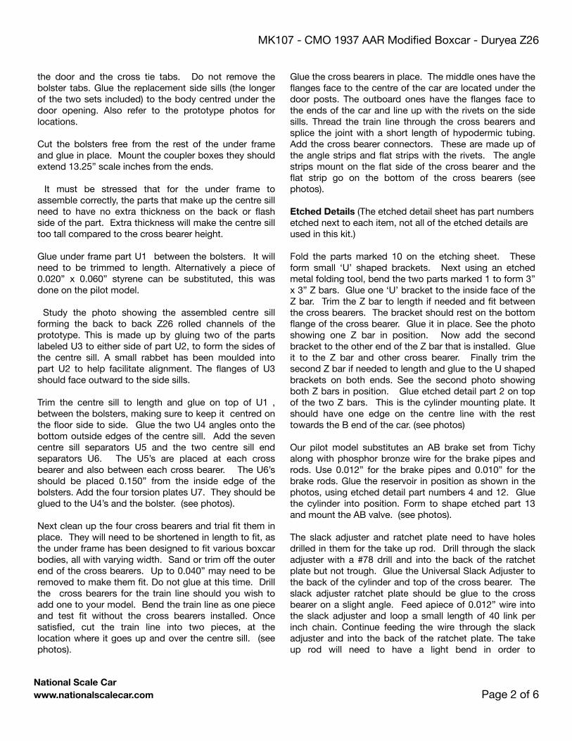
In 1945, The Chicago, St.Paul, Minneapolis & Omaha took delivery of 400, 40' boxcars, in two orders placed with American Car & Foundry. The orders specified 10’6” interior height, 6’ doors, Murphy Panel Roofs, 4-4 Improved Dreadnought ends with poling pockets and built to the 1937 AAR Modified standard, but with the unique Duryea cushioned under frame with Z26 centre sill.
The as-delivered slogan stencilled onto these cars was ‘Route of the 400 Fleet’ with Black Ends. The decals in this kit, cover as built cars and repaints with the same scheme. Photo evidence shows the cars could have been repainted with ends matching the sides.
Instructions
Three parts lists are included at the end of these instructions. Parts Included in This Kit needs no explanation. Parts Sourced by the Modeller identify what the modeller must supply.
The level of detail you choose for your model will affect
the construction time. A model built with the parts included with the Intermountain kit will yield a fine model, but substituting from the third list of Suggested Optional Parts will yield a more accurate car. Of course, the savvy model builder might find ways to enhance their model beyond what's outlined in these instructions, and we'd love to see your work.
Construction
Start off by cleaning the resin parts of any remaining mold release. Cleaning with ‘Shout’, orange type degreaser or dish soap and water will all give satisfactory results. Remove flash from the resin details by sanding on a flat surface such as plate glass or a bench top. 220-grit sandpaper works well for this. Take your time and make sure to sand the parts to an even thickness. Rotate the part as you go to ensure you don’t sand any one area more than the rest of the part. If the castings have any small pin holes, they can be filled with auto body glazing compound or Squadron filler for plastic models.
Remove any remains of the injection sprue from the bottom of the car body along with the cast on mounts for the cylinder and reservoir. Carve off the side sills under
# Series Quantity Built
(Month) Year Built
Door Type Brake type Builder Running Board
37500-38098 300 (8) 1945 Youngstown Ajax ACF Apex 200Gypsum 100
38100-38298 100 (8) 1945 Superior 7 Panel
Universal ACF Gypsum
Col. Chet McCoid - Bob’s Photos
MK107 - CMO 1937 AAR Modified Boxcar - Duryea Z26
National Scale Car www.nationalscalecar.com Page of 2 6
the door and the cross tie tabs. Do not remove the bolster tabs. Glue the replacement side sills (the longer of the two sets included) to the body centred under the door opening. Also refer to the prototype photos for locations.
Cut the bolsters free from the rest of the under frame and glue in place. Mount the coupler boxes they should extend 13.25” scale inches from the ends.
It must be stressed that for the under frame to assemble correctly, the parts that make up the centre sill need to have no extra thickness on the back or flash side of the part. Extra thickness will make the centre sill too tall compared to the cross bearer height.
Glue under frame part U1 between the bolsters. It will need to be trimmed to length. Alternatively a piece of 0.020” x 0.060” styrene can be substituted, this was done on the pilot model.
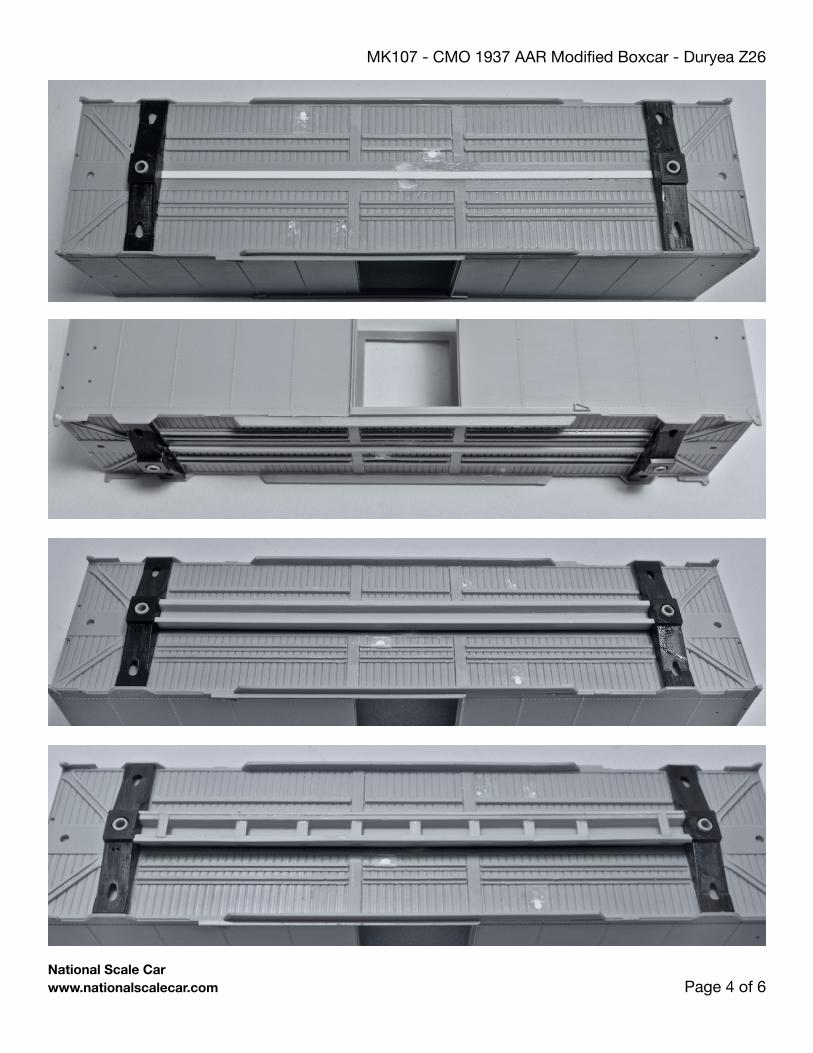
Study the photo showing the assembled centre sill forming the back to back Z26 rolled channels of the prototype. This is made up by gluing two of the parts labeled U3 to either side of part U2, to form the sides of the centre sill. A small rabbet has been moulded into part U2 to help facilitate alignment. The flanges of U3 should face outward to the side sills.
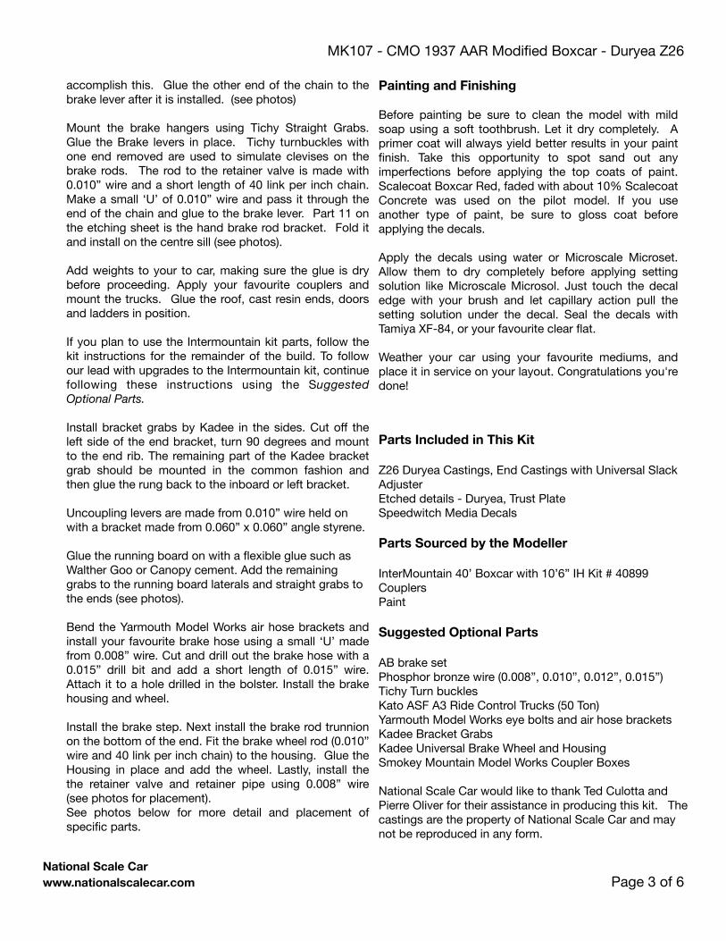
Trim the centre sill to length and glue on top of U1 , between the bolsters, making sure to keep it centred on the floor side to side. Glue the two U4 angles onto the bottom outside edges of the centre sill. Add the seven centre sill separators U5 and the two centre sill end separators U6. The U5’s are placed at each cross bearer and also between each cross bearer. The U6’s should be placed 0.150” from the inside edge of the bolsters. Add the four torsion plates U7. They should be glued to the U4’s and the bolster. (see photos).
Next clean up the four cross bearers and trial fit them in place. They will need to be shortened in length to fit, as the under frame has been designed to fit various boxcar bodies, all with varying width. Sand or trim off the outer end of the cross bearers. Up to 0.040” may need to be removed to make them fit. Do not glue at this time. Drill the cross bearers for the train line should you wish to add one to your model. Bend the train line as one piece and test fit without the cross bearers installed. Once satisfied, cut the train line into two pieces, at the location where it goes up and over the centre sill. (see photos).
Glue the cross bearers in place. The middle ones have the flanges face to the centre of the car are located under the door posts. The outboard ones have the flanges face to the ends of the car and line up with the rivets on the side sills. Thread the train line through the cross bearers and splice the joint with a short length of hypodermic tubing. Add the cross bearer connectors. These are made up of the angle strips and flat strips with the rivets. The angle strips mount on the flat side of the cross bearer and the flat strip go on the bottom of the cross bearers (see photos).
Etched Details (The etched detail sheet has part numbers etched next to each item, not all of the etched details are used in this kit.)
Fold the parts marked 10 on the etching sheet. These form small ‘U’ shaped brackets. Next using an etched metal folding tool, bend the two parts marked 1 to form 3” x 3” Z bars. Glue one ‘U’ bracket to the inside face of the Z bar. Trim the Z bar to length if needed and fit between the cross bearers. The bracket should rest on the bottom flange of the cross bearer. Glue it in place. See the photo showing one Z bar in position. Now add the second bracket to the other end of the Z bar that is installed. Glue it to the Z bar and other cross bearer. Finally trim the second Z bar if needed to length and glue to the U shaped brackets on both ends. See the second photo showing both Z bars in position. Glue etched detail part 2 on top of the two Z bars. This is the cylinder mounting plate. It should have one edge on the centre line with the rest towards the B end of the car. (see photos)
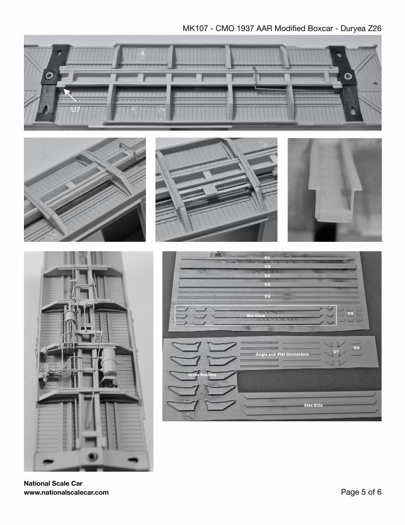
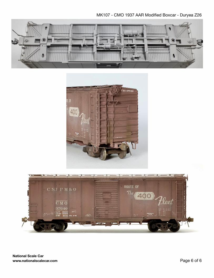
Our pilot model substitutes an AB brake set from Tichy along with phosphor bronze wire for the brake pipes and rods. Use 0.012” for the brake pipes and 0.010” for the brake rods. Glue the reservoir in position as shown in the photos, using etched detail part numbers 4 and 12. Glue the cylinder into position. Form to shape etched part 13 and mount the AB valve. (see photos).
The slack adjuster and ratchet plate need to have holes drilled in them for the take up rod. Drill through the slack adjuster with a #78 drill and into the back of the ratchet plate but not trough. Glue the Universal Slack Adjuster to the back of the cylinder and top of the cross bearer. The slack adjuster ratchet plate should be glue to the cross bearer on a slight angle. Feed apiece of 0.012” wire into the slack adjuster and loop a small length of 40 link per inch chain. Continue feeding the wire through the slack adjuster and into the back of the ratchet plate. The take up rod will need to have a light bend in order to
MK107 - CMO 1937 AAR Modified Boxcar - Duryea Z26
National Scale Car www.nationalscalecar.com Page of 3 6
accomplish this. Glue the other end of the chain to the brake lever after it is installed. (see photos)
Mount the brake hangers using Tichy Straight Grabs. Glue the Brake levers in place. Tichy turnbuckles with one end removed are used to simulate clevises on the brake rods. The rod to the retainer valve is made with 0.010” wire and a short length of 40 link per inch chain. Make a small ‘U’ of 0.010” wire and pass it through the end of the chain and glue to the brake lever. Part 11 on the etching sheet is the hand brake rod bracket. Fold it and install on the centre sill (see photos).
Add weights to your to car, making sure the glue is dry before proceeding. Apply your favourite couplers and mount the trucks. Glue the roof, cast resin ends, doors and ladders in position.
If you plan to use the Intermountain kit parts, follow the kit instructions for the remainder of the build. To follow our lead with upgrades to the Intermountain kit, continue following these instructions using the Suggested Optional Parts.
Install bracket grabs by Kadee in the sides. Cut off the left side of the end bracket, turn 90 degrees and mount to the end rib. The remaining part of the Kadee bracket grab should be mounted in the common fashion and then glue the rung back to the inboard or left bracket.
Uncoupling levers are made from 0.010” wire held on with a bracket made from 0.060” x 0.060” angle styrene.
Glue the running board on with a flexible glue such as Walther Goo or Canopy cement. Add the remaining grabs to the running board laterals and straight grabs to the ends (see photos).
Bend the Yarmouth Model Works air hose brackets and install your favourite brake hose using a small ‘U’ made from 0.008” wire. Cut and drill out the brake hose with a 0.015” drill bit and add a short length of 0.015” wire. Attach it to a hole drilled in the bolster. Install the brake housing and wheel.
Install the brake step. Next install the brake rod trunnion on the bottom of the end. Fit the brake wheel rod (0.010” wire and 40 link per inch chain) to the housing. Glue the Housing in place and add the wheel. Lastly, install the the retainer valve and retainer pipe using 0.008” wire (see photos for placement).See photos below for more detail and placement of specific parts.
Parts Included in This Kit
Z26 Duryea Castings, End Castings with Universal Slack AdjusterEtched details - Duryea, Trust PlateSpeedwitch Media Decals
Parts Sourced by the Modeller
InterMountain 40’ Boxcar with 10’6” IH Kit # 40899CouplersPaint
Suggested Optional Parts
AB brake setPhosphor bronze wire (0.008”, 0.010”, 0.012”, 0.015”)Tichy Turn bucklesKato ASF A3 Ride Control Trucks (50 Ton)Yarmouth Model Works eye bolts and air hose bracketsKadee Bracket GrabsKadee Universal Brake Wheel and HousingSmokey Mountain Model Works Coupler Boxes
National Scale Car would like to thank Ted Culotta and Pierre Oliver for their assistance in producing this kit. The castings are the property of National Scale Car and may not be reproduced in any form.
Painting and Finishing
Before painting be sure to clean the model with mild soap using a soft toothbrush. Let it dry completely. A primer coat will always yield better results in your paint finish. Take this opportunity to spot sand out any imperfections before applying the top coats of paint. Scalecoat Boxcar Red, faded with about 10% Scalecoat Concrete was used on the pilot model. If you use another type of paint, be sure to gloss coat before applying the decals.
Apply the decals using water or Microscale Microset. Allow them to dry completely before applying setting solution like Microscale Microsol. Just touch the decal edge with your brush and let capillary action pull the setting solution under the decal. Seal the decals with Tamiya XF-84, or your favourite clear flat.
Weather your car using your favourite mediums, and place it in service on your layout. Congratulations you're done!
MK107 - CMO 1937 AAR Modified Boxcar - Duryea Z26
National Scale Car www.nationalscalecar.com Page of 4 6
MK107 - CMO 1937 AAR Modified Boxcar - Duryea Z26
National Scale Car www.nationalscalecar.com Page of 5 6
U7
MK107 - CMO 1937 AAR Modified Boxcar - Duryea Z26
National Scale Car www.nationalscalecar.com Page of 6 6