Embed Size (px)
Citation preview

AWMITSUBISHI HEAVY INDUSTRIES, LTD.
16-5, KONAN 2-CHOME, MINATO-KUTOKYO, JAPAN
October 4, 2011
Document Control DeskU.S. Nuclear Regulatory CommissionWashington, DC 20555-0001
Attention: Mr. Jeffrey A. Ciocco
Docket No. 52-021MHI Ref: UAP-HF-11338
Subject: MHI's Amended Responses to US-APWR DCD RAI for Chapter 7,Response to the Additional Questions from the NRC
References: 1) "REQUEST FOR ADDITIONAL INFORMATION 734-5659 REVISION 5, SRPSection: 07.01 - Instrumentation and Controls Introduction, ApplicationSection: 07-14 Branch Technical Position - Guidance on Software Reviewsfor Digital Computer-Based Instrumentation and Control Systems" datedApril 18,2011.
With this letter, Mitsubishi Heavy Industries, Ltd. ("MHI") transmits to the U.S. NuclearRegulatory Commission ("NRC") documents as listed in Enclosures.
Enclosure 1 is the amended responses to RAls contained within Reference 1. The responsesare revised according to the staffs comments, provided in conference calls held from June toSeptember, on the original responses to the RAI dated May 31st, 2011.
Enclosure 2 is the responses to additional questions from the NRC on conference calls held inSeptember, 2011.
Please contact Dr. C. Keith Paulson, Senior Technical Manager, Mitsubishi Nuclear EnergySystems, Inc. if the NRC has questions concerning any aspect of this submittal. His contactinformation is provided below.
Sincerely,
Yoshiki Ogata,General Manager- APWR Promoting DepartmentMitsubishi Heavy Industries, LTD.

Enclosures:
1. Amended Response to Request for Additional Information for Chapter 7
2. Response to the Additional Questions from the NRC
CC: J. A. CioccoC. K. Paulson
Contact InformationC. Keith Paulson, Senior Technical ManagerMitsubishi Nuclear Energy Systems, Inc.300 Oxford Drive, Suite 301Monroeville, PA 15146E-mail: [email protected]: (412) 373-6466

Enclosure 1
Docket No. 52-021UAP-HF-11338
Amended Response to Request for Additional Informationfor Chapter 7
October, 2011

This Enclosure includes following response of RAIs
RAI No. 734-5659 Revision 5, Question No.: 07.01-37
RAI No. 734-5659 Revision 5, Question No.: 07.01-38
RAI No. 734-5659 Revision 5, Question No.: 07.01-39
1-1

RESPONSE TO REQUEST FOR ADDITIONAL INFORMATION
10/04/2011
US-APWR Design Certification
Mitsubishi Heavy Industries
Docket No. 52-021
RAI NO.: NO.734-5659 REVISION 5
SRP SECTION: 07.01 - INSTRUMENTATION AND CONTROLS -INTRODUCTION
APPLICATION SECTION: 07-14 BRANCH TECHNICAL POSITION - GUIDANCE ONSOFTWARE REVIEWS FOR DIGITAL COMPUTER-BASED INSTRUMENTATIONAND CONTROLS SYSTEMS
DATE OF RAI ISSUE: 04118/2011
QUESTION NO. : 07.01-37
General Design Criterion 1, "Quality Standards and Records," of Appendix A, "GeneralDesign Criteria for Nuclear Power Plants," to 10 CFR Part 50 requires, in part, thatappropriate records of the design and testing of systems and components important tosafety be maintained. Regulatory Guide (RG) 1.172, Software RequirementsSpecifications, which endorses IEEE Std 830-1993, describes a method acceptable tothe NRC staff for complying with the NRC's regulations for achieving high functionalreliability and design quality in software used in safety systems. In particular, the methodis considered consistent with GDC 1 and the criteria for quality assurance programs inAppendix B as they apply to the development of software requirements specifications.
In Section 3.9.8.1, "Plant Requirements Phase SSA," of the Application SoftwareProgram Manual (SPM), MUAP-07017, Rev. 3, on page 3.9-9, states "This phase ofdevelopment is referred to as the Software Requirements Specification (SRS)." From thestaffs perspective, the SRS is not a phase but a complete document associated with RG1.172 as noted above. This document is not related to one phase but remains andevolves even if all details are not available at the time the project is initiated as IEEE Std830-1993 explains. The staff requests MHI to address this and to revise Section 3.9.8.1as necessary and ensure that the purpose and use of the SRS are consistent with thereferenced RG.
ANSWER:
MHI agrees to the NRC's comment that "the SRS is not a phase," and the secondparagraph of Section 3.9.8.1 of the Application Software Program Manual, MUAP-07017,will be revised as follows:
1-2

This phase of developmont The Plant Requirements Phase SSA is referred to asthe Softw'aro RequiF8remets Specification (SRS) de6cription in Section 3.2.1 and4.2.2 of NUREG/CR 6101 and the Software Safety Analysis Preparation, as definedin Section 4.4.1 of IEEE Std. 1228-1994.
The software requirements to achieve high functional reliability and design quality insoftware used in safety systems are specified within the System RequirementsSpecification (SysRS) as described in Sections 3.2.6.2.1 and 3.9.8.2. The SysRS will bedeveloped and documented during the System Requirements Phase. Associatedsoftware safety analysis activities are performed as described in Section 3.9.8.2 "SystemRequirements Phase SSA," based on the output of the Plant Requirements Phase SSA.
The SysRS is developed and documented to conform with IEEE Std 830-1993(Reference 7) as endorsed by Regulatory Guide 1.172 (Reference 17). Thesecommitments for the software requirements specifications, within the SysRS, are alreadydescribed in the last paragraph of Section 3.2.6.2.1.
The first paragraph of Section 3.9.8.1 of the Application Software Program Manual,MUAP-07017, will be revised to clearly describe the purpose of the Requirements SafetyAnalysis as follows;
The purpose of the SSA conducted during the Plant Requirements Phase is toidentify any errors or deficiencies that could contribute to a hazard and to identifysystem safety considerations that are not addressed in the software requirementsspecified in the System Requirements Specification (SysRS), which will bedeveloped during the System Requirements Phase as described in Section 3.9.8.2.The ..fume-ef-the SSA conducted during the Plant Requirements Phase is toestablish the fundamental US-APWR plant critical safety characteristics as theyaffect the design and implementation of application software used in the PSMS.
The first paragraph of Section 3.9.8.2.6 will be revised to clearly describe the timing ofthe Requirements Safety Analysis as follows;
AlI-eSafety critical requirements for the PSMS application software have beengenerically analyzed and evaluated against the key safety qualities and have beendescribed in the US-APWR DCD Chapter 7 and the related technical reports. Foreach US-APWR proiect, the DT shall review these generic safety critical PSMSapplication software requirements, confirm their applicability to the project, identifyany proiect-specific changes from or additions to the generic safety criticalrequirements, and include the results in the promect-specific SysRS. For each US-APWR project, the SysRS describes Functional Requirements and FunctionalDiagram (FD) for PSMS functions. Following development of the proiect-specificSysRS, the SSA activities performed in the System Requirements Phase for eachUS-APWR Project shall identify any system safety considerations not identified inthe SysRS.
Impact on DCD
1-3

There is no impact on the DCD.
Impact on R-COLAThere is no impact on the R-COLA.
Impact on S-COLAThere is no impact on the S-COLA.
Impact on PRAThere is no impact on the PRA.
Impact on Technical / Topical ReportsImpacts on the Technical Report MUAP-07017 are described in the above answer.
1-4

RESPONSE TO REQUEST FOR ADDITIONAL INFORMATION
10/04/2011
US-APWR Design Certification
Mitsubishi Heavy Industries
Docket No. 52-021
RAI NO.: NO.734-5659 REVISION 5
SRP SECTION: 07.01 - INSTRUMENTATION AND CONTROLS -INTRODUCTION
APPLICATION SECTION: 07-14 BRANCH TECHNICAL POSITION - GUIDANCE ONSOFTWARE REVIEWS FOR DIGITAL COMPUTER-BASED INSTRUMENTATIONAND CONTROLS SYSTEMS
DATE OF RAI ISSUE: 0411812011
QUESTION NO. : 07.01-38
Appendix B to 10 CFR Part 50 contain requirements that extend to software life cycleactivities. Criterion Ill, "Design Control," requires measures to ensure that applicableregulatory requirements and the design basis for those structures, systems, andcomponents to which Appendix B applies are correctly translated into specifications,drawings, procedures, and instructions.
Regulatory Guide (RG) 1.173, which endorses IEEE Std 1074-1995, DevelopingSoftware Life Cycle Processes, states:
1) [See section C. 1.1] In addressing Appendix B, Criterion III, the descriptions ofinput information, life cycle activity, and output information that are required byIEEE Std 1074-1995 must identify applicable regulatory requirements, designbases, and related guidance;
2) [See section C. 3.] To ensure that safety system software development isconsistent with the defined system safety analyses, additional activities beyondthose specified in IEEE Std 1074-1995 are necessary. Planned and documentedsoftware safety analysis activities should be conducted for each phase of thesoftware development life cycle. RG 1.173 also identifies the inputs, activitydescriptions and outputs for the software safety analysis.
Section 3.9.8.1, "Plant Requirements Phase SSA," of the Application Software ProgramManual, MUAP-07017, Rev. 3, on page 3.9-9, states "All SSA (Software Safety Analysis)activities which shall be performed during the plant requirements phase have all beencompleted and finished for the generic US-APWR plant and the results of these SSA aredescribed in the US-APWR DCD, including Chapter 7, Chapter 15, Chapter 19 and therelated technical reports." The staff finds this unacceptable as it does not follow the
1-5

guidance as explained above. An SSA cannot be provided through the "body" ofinformation submitted for the US-APWR design certification.
In addition, BTP 7-14 references NUREG/CR-6101 (as does MHI). In this guidance,Section 4.2.2, Requirements Safety Analysis, states that "The purpose of the safetyanalysis is to identify any errors or deficiencies that could contribute to a hazard and toidentify system safety considerations not addressed in the SRS."
Therefore, MHI is requested to address this issue and to revise the SPM to indicate aplanned and documented SSA will be completed for the Requirements Phase when therequirements phase is completed. Consistent with the guidance stated above, MHIshould indicate the SSA will be complete when the SRS has been completed andevolved to a complete document.
ANSWER:
The SSA activities of the Plant Requirements Phase will be performed for each US-APWR project based on the results of the generic SSA activities which have beencompleted at the US-APWR DCD phase, and these SSA activities will be documentedand complete when the ITAAC are complete.
The ITAAC for the plant requirements phase in the software lifecycle process includesthe SSA activities that are already described in Tier-1 as follows:
Design Commitment: 24.iSoftware Program Manual (SPM) is implemented to manage the PSMS softwarelifecycle process in each software lifecycle phase.
Inspection, Test, Analyses: 24.JAn inspection will be performed for the plant requirements phase result summaryreport of PSMS software in accordance with the SPM.
Acceptance Criteria: 24.1The plant requirements phase result summary report exists and concludes that theplant requirements phase activities of PSMS software are performed in accordancewith the SPM.
To clarify the commitment to perform SSA activities in accordance with RG 1.173 foreach US-APWR project, the following description will be added in a new paragraphbelow the first paragraph of Section 3.9.8:
Phase-specific SSA activities are described in Sections 3.9.8.1 through 3.9.8.6, andthey correspond with the phases of the PSMS application software development lifecycle described in this SPM. These SSA activities shall be conducted anddocumented within each proiect-specific phase in accordance with RG 1.173(Reference 22) per the following steps:
1-6

(1) Identify Required Input Information" Regulatory requirements and guidance" Information reported for the system safety analysis* Information from previous phases for the SSA
* The design information from previous and current system and softwarephases activities
(2) Perform Required AnalysesThe analyses must ensure that:
" System safety requirements have been correctly addressed," No new hazards have been introduced," Software elements that can affect safety are identified," There is evidence that other software elements do not affect safety, and" Safety problems and resolutions identified in these analyses are documented.
(3) Document Required Output InformationInformation for the current phase activities shall be reported in the SSA. Thisinformation should be used for the design activities of current life cycle phase,subsequent SSA activities, the software configuration management process,and the verification and validation process.
The US-APWR DCD and related technical r'eports will be reviewed by the Design Team(DT) and verified by the V&V Team (VVT) during the Plant Requirements Phase of eachUS-APWR project, and the results of the DT review and WT verification aredocumented as project-specific SSA reports by the DT. Also, the DT will add project-specific SSA activities in these reports which are performed based on project-specificsystem and software requirements that are developed in the Plant Requirements Phase.The results of the VVT verification are also documented in phase-specific V&V SummaryReports as described in Section 3.10.
The third paragraph of Section 3.9.8.1 will be revised to clearly describe the generic SSAactivities in Section 3.9.8.1.1 through 3.9.8.1.5, and remove references to the DCD andtechnical reports as follows:
All generic SSA (Software Safety Analysis) activities whigh shall be performedduring the Plant Requirements Phase hn'-e bhn ccmpg•ted fGr the q9.enk 'USADPAID Wa-.-t a~ the~ Fe'"R P ~ tpq- SA Rrp Orl tho USH APVRD~ADf(
,,,I,•,,,-/ G,,(i' 7, Ghai-e. 7 vp ,I IA-v , ;,a10 +,, a , e, +,-.,nIv, F8394& as
described in Sections 3.9.8.1.1 through 3.9.8.1.5.
The following paragraphs will be inserted after the third paragraph of Section 3.9.8.1:
The DT shall review the US-APWR DCD, including Chapter 7. Chapter 15, Chapter19 and the related technical reports as described in Sections 3.9.8.1.1 throuqh3.9.8.1.5 to identify the followinq items for each US-APWR proiect:
1-7

(1) Scope of safety functions which will be performed by software.(2) Interfaces between the software and the rest of the safety system.(3) MELTAC Platform design changes from the US-APWR DCD Phase.
If the scope, interface or the MELTAC Platform design is chan-ged, the followingrelated Plant Requirements Phase SSA as described in Sections 3.9.8.1.1 through3.9.8.5 shall be performed for the changed portion.
The results of the above review shall be documented as the proiect-specific SSAreports by the DT and shall be independently verified by the VVT.
The last paragraph of Section 3.9.8.1 will be revised as follows:
Output documents of The following SSA reports for each US-APWR project,including necessary chan-qes based on the above review, are output documents ofthe Plant Requirements Phase (the US APWR de60GI, c"rtOiOfato• n ,ha•e., andthese documents are inputs for the SSA duringq the System Requirements Phase inthe PSMS application software life cycle process for each US-APWR project.
- Report which describes the results of Preliminary Hazard Analysis- Report which describes the results of Response Time Analysis- Report which describes the results of Criticality Analysis- Report which describes the results of Diversity and Defense-in-Depth Analysis- Report which describes the results of FMEA and Reliability Analysis
The SSA reports for each US-APWR project are documented at the Plant RequirementsPhase as described above, therefore inputs documents at the Plant RequirementsPhase will be revised as follows.
The first paragraph of Section 3.9.8.2.1 will be revised as follows:
The results of the preliminary hazard analysis are described in the SSA report whichis documented at the Plant Requirements Phase technicAl roport JEX'J 1015 1009"MErL TAt" DIa-#9FM,-- Bas-'Gr Seftwa,.•.- SafeW, -14o"lý
The first paragraph of Section 3.9.8.2.2 will be revised as follows:
The results of the response time analysis are described in the SSA report which isdocumented at the Plant Requirements Phase. The ........ time all-,atikos..... i ..... M. • IAP 09021.
The first paragraph of Section 3.9.8.2.3 will be revised as follows:
The results of the criticality analysis for the PSMS interdivision communicationinterfaces are described in the SSA report which is documented at the PlantRequirements Phase in Appndi D;of tho tech nial .... F8nd4 Doei.n-PFGG8e6.
1-8

The first paragraph of Section 3.9.8.2.4 will be revised as follows:
The results of the diversity and defense-in-depth analysis are described in the SSAreport which is documented at the Plant Requirements Phase. The rosult of D3a.,a.1s. .......... ,v ,..F G pf. , A ,,al.y& •.
The first paragraph of Section 3.9.8.2.5 will be revised as follows:
The results of the PSMS FMEA and reliability analysis are described in the SSAreport which is documented at the Plant Requirements Phase in the DCD ..........Probabilistic Risk Assessment".
The first paragraph of Section 3.9.8.2.6 will be revised as follows:
Alt-eSafety critical requirements for the PSMS application software have beengenerically analyzed and evaluated against the key safety qualities and have beendescribed in the US-APWR DCD Chapter 7 and the related technical reports. Foreach US-APWR project, the DT shall review these generic safety critical PSMSapplication software requirements, confirm their applicability to the proiect, identifyany proiect-specific changes from or additions to the generic safety criticalrequirements, and include the results in the proiect-specific SysRS. For each US-APWR proiect, the SysRS describes Functional Requirements and FunctionalDiagram (FD) for PSMS functions. Following development of the proiect-specificSysRS, the SSA activities performed in the System Requirements Phase for eachUS-APWR Proiect shall identify any system safety considerations not identified inthe SvsRS.
Impact on DCDThere is no impact on the DCD.
Impact on R-COLAThere is no impact on the R-COLA.
Impact on S-COLAThere is no impact on the S-COLA.
Impact on PRAThere is no impact on the PRA.
Impact on Technical / Topical ReportsImpacts on the Technical Report MUAP-07017 are described in the above answer.
1-9

RESPONSE TO REQUEST FOR ADDITIONAL INFORMATION
1010412011
US-APWR Design Certification
Mitsubishi Heavy Industries
Docket No. 52-021
RAI NO.: NO.734-5659 REVISION 5SRP SECTION: 07.01 - INSTRUMENTATION AND CONTROLS -
INTRODUCTION
APPLICATION SECTION: 07-14 BRANCH TECHNICAL POSITION - GUIDANCE ONSOFTWARE REVIEWS FOR DIGITAL COMPUTER-BASED INSTRUMENTATIONAND CONTROLS SYSTEMS
DATE OF RAI ISSUE: 04/18/2011
QUESTION NO. : 07.01-39
Appendix B to 10 CFR Part 50 contains requirements that extend to software life cycleactivities. Criterion III, "Design Control," requires measures to ensure that applicableregulatory requirements and the design basis for those structures, systems, andcomponents to which Appendix B applies are correctly translated into specifications,drawings, procedures, and instructions.
Regulatory Guide 1.173, which endorses IEEE Std 1074-1995, Developing Software LifeCycle Processes, states:
(1) In addressing Appendix B, Criterion Ill, the descriptions of input information, lifecycle activity, and output information that are required by IEEE Std 1074-1995must identify applicable regulatory requirements, design bases, and relatedguidance;
(2) To ensure that safety system software development is consistent with the definedsystem safety analyses, additional activities beyond those specified in IEEE Std1074-1995 are necessary. Planned and documented software safety analysisactivities should be conducted for each phase of the software development lifecycle. RG 1.173 also identifies the inputs, activity descriptions and outputs for thesoftware safety analysis.
Section 3.9.8.2.1, Preliminary Hazard Analysis, on Page 3.9-12 of the ApplicationSoftware Program Manual (MUAP-07017, Rev. 3) states that, "The results of thepreliminary hazard analysis are described in the technical report, JEXU-1015-1009,"MELTAC Platform Basic Software Safety Report.""
1-10

Section 3.9.5.1.1, Hazard Analysis, on Page 88 of the Basic Software Program Manual(JEXU-1012-1132, Rev. 2), states that, "All hazards defined were evaluated anddocumented in the MELTAC Software Safety Report (JEXU-1015-1009)."However, the staff does not consider the MELTAC Software Safety Report (JEXU-1015-1009) to be a Software Safety Analysis (as discussed in RAI 665-5220). Therefore, thestaff requests MHI to address this issue and remove this document as a reference for asoftware safety analysis in the Basic SPM and the Application SPM.
ANSWER:
Section 3.9.8.1.1 "Preliminary Hazard Analysis" only describes the analysis for the basicsoftware and the MELTAC platform.
Other analyses which include the system level hazard analyses for the entire safetysystems (PSMS) of the US-APWR including the application software of the PSMS aredescribed through Section 3.9.8.1.2 to 3.9.8.1.5 for the Plant Requirements Phase.
The last paragraph of Section 3.9.8.1.1 will be revised to identify that Section 3.9.8.1.1"Preliminary Hazard Analysis" only describes the analysis for the basic software and theMELTAC platform as follows;
The PSMS of each US-APWR project is implemented through the software andhardware of the MELTAC platform and other, connected components such assensors and reactor trip breakers. The MELTAC platform hazard analysis describedin the Appendix E of the MELTAC Technical Report (JEXU-1011-1002) teehRiGalrepo.t J.XU 1015 1009 .ELTA. Platform B.asic Software Safety Report",establishes the preliminary hazards analysis for the MELTAC platform PSMS. Thisanalysis confirms that the MELTAC platform can prevent hazardous systems statesdue to any conditions within the platform, including software and hardware, andi n 1uding the inter-division communication design. The analysis also confirms thatinternal hardware or software failures that result in hazardous system states can beeither automatically or manually detected. Detection allows correction before theconcurrence of hazardous states in multiple PSMS divisions. The system levelpreliminary hazard analysis for the entire PSMS, including the overall systemconfiguration, the redundancies and the components (process and actuatingdevices) except the MELTAC platform, are described through Section 3.9.8.1.2 to3.9.8.1.5.
The first paragraph of Section 3.9.8.2.1 will be revised additionally (in bold) from therevised description in the response to RAI 07.01-38 to identify the system levelpreliminary hazard analyses as follows;
The results of the MELTAC platform level and the system level preliminary hazardanalyses are described in the SSA reports which are documented at the PlantRequirements Phase techn.cal •rep.t JEXU 1015 1009 "MELTAC Platform B+cicSftware Safety Report". These SSA reports shall account for additional systemlevel hazards not already addressed at the MELTAC platform level (as described in
1 -11

Section 3.9.8.1.1) by taking into account the overall system configuration, systemredundancies, and system functions. These SSA reports shall identify the basicMELTAC platform design, the hi-gh level system desigqn and versions to identifyincluded components, process and actuating devices to determine what the hazardanalysis is done on and if it has to be re-evaluated.
For the MELTAC platform level preliminary hazard analysis, the 20 events pertainingnetwork error listed in Section 3.2 of JEXU-1015-1009 correspond to external datacommunication hazards, general hazards pertaining to communication defined in DI&CISG-04 and NUREG/CR-6991, for the MELTAC platform.
Since the sections of JEXU-1015-1009 that identify and analyze the events (Section 3.2and Section 3.5) are a part of the Preliminary Hazard Analysis for the MELTAC platform,they have been referenced in the SSP of the SPM. However, the current reference inthe SPM may be misunderstood that the entire ISG-04 Conformance Analysis is theSoftware Safety Analysis of MELTAC Platform. To address the NRC concern, MHI willtake actions as follows.
All references to MELTAC Platform ISG-04 Conformance Analysis" (JEXU-1015-1009)for a software safety analysis in the Basic SPM and the Application SPM will be removed.
The following will be added to MELTAC Technical Report (MUAP-07005), appendix E"Software Critical Function Analysis".
(1) Hazards in external communication data described in Section 1.12 of ISG-04.(2) Section numbers of JEXU-1015-1009 that contain the analysis result of the above
hazards.(3) Distinction between faults that can be mitigated and hazards that cannot be
mitigated in the platform.The result of the analysis above will be one of the inputs to the system level PHA.
The above description will be added to Appendix E of the MELTAC Technical Report todistinguish a fault and a hazard.
Impact on DCDThere is no impact on the DCD.
Impact on R-COLAThere is no impact on the R-COLA.
Impact on S-COLAThere is no impact on the S-COLA.
Impact on PRAThere is no impact on the PRA.
Impact on Technical / Topical Reports
1-12

Impacts on the Technical Report MUAP-07017 and MUAP-07005 are described in theabove answer.
This completes MHI's responses to the NRC's questions.
1 -13

Enclosure 2
Docket No. 52-021UAP-H F-11338
Response to Additional Questions from the NRC
October, 2011

ResDonses to the Additional Questions from the NRC(Sheet 1 of 1)
No. Additional Questions from the NRC Response to the Questions from MHI Documents to be Revised
1 In the DCD Rev.3, concerning Tables 7.2-3/4 Although MHI is using the terminology of "Nominal DCD Chapter 7 markup"Reactor Trip Variables, Ranges, Accuracies, Trip Setpoint" for consistency between Ch7 andResponse Times, and Setpoints (Nominal)." Did Chl6 (Tech Spec), MHI agrees to modify footnote 3MHI propose those as nominal trip setpoints based in Table 7.2-3, footnote 4 in Table 7.3-4, andon their setpoint methodology? footnote 3 in Table 7.8-6 to note the setpoint values
are typical (not the plant-specific values to becalculated based on the setpoint methodology), andplant-specific Nominal Trip Setpoint values shall berecorded and maintained in a document establishedby Chapter 16, Specification 5.5.21 (SetpointControl Program).See the proposed markup of Attachment-i. (Basemarkup is the one which was submitted on 5/31 withthe letter, UAP-HF-11159.)
2 The staff is asking for clarifications on how the DAS Outputs from the DAS are interfaced to the plant N/A
is adequately independent from the PSMS since components via discrete hardware logic in the PIFthe DAS signals go through the PIF module and module of the PSMS. The PIF module is nothow a failure of the PSMS system itself doesn't susceptible to a software CCF because it consist ofaffect the DAS availability. The staff understands proven simple and fully testable hardware devices,that the DAS signals enter the PIF module (see as described in section 6.2.4 of the D3 Topicaldiscussion in Section 3.0 of MUAP-07005 under Report, MUAP-07006 and section 4.1.2.4 of the
item 6, 10 CFR 50.62 ATWS Rule), but the staff is MELTAC Technical Report, MUAP-07005. Theseconcerned that during a CCF that affects the DAS outputs are electrically isolated and the safePSMS (losing parts of PSMS or the system state signal always has priority for combining theentirely), how is the PIF module not affected by a SLS and DAS signals. These design features are
CCF so that DAS can complete its intended described in Sections 4.2.3, 4.2.6, 5.1.7 and 5.1.13functions? of the Safety I&C Technical Report, MUAP-07004.

"Response to the Additional Questions from the NRC" Attachment-1
7. INSTRUMENTATION AND CONTROLS US-APWR Design Control Document
Table 7.2-3 Reactor Trip Variables, Ranges, AssumosloeChannel Uncertainties,Response Times, and Nominal TripSetpoints (NeminaI) (Sheet 3 of 3) I
RT Function Variables to be Range of Variables &wimument- Response Nominalmonitored MQvFmeGY Time*,' r
Channel IdLUncertaintl * Setpoint*
3
1,2
EGGS Aetuagion PreeeOrlaeS- 4700- to 26900 = 2.59eopeR & ee :176. PaloPeseuwe
Moon Bl1etom LWno 0 94e-409-peig4 O-f ePOR' &&.eee 626 psi@
GSR,^.*•. -, i son -- 2.84.%is aQ see 69 P63
Reactor Trio on Turbine Emergency 0 to 3500psig 2±1A% of 1.0 sec 1000 psigTurbine Trip Trip Oil Pressure span
Main Turbine Stop N/A N/A 1.0 sec 5% openValve Position
DCD_14.03.05-12
DCD_07.01-30
DCD_07.01-29
DCD_07.01-29
MIC-03-07-00009
I DCD_14.03.05-12DCD_07.01-29
Note1.
2.
3.
4.5.6.7.8.
:b"Jl
lnrtRMAInt OcaNulO and mctpodoo reMe tARzzo tihe toithcd olcoY aFvr teh uboigRorn 7.2.2.7.-Channeluctanycalculation methodology refers to the Setpoint Methodoiggv Technical Renort Ref. 7.2-1 31.
l-noRummnts. Channel uncertainties in this table are typical values. Channel uncertainties will bedetermined to take into account the spefification of instruments
...P.I ,Will h ...U.....d !GOP ..O....Nominal Trip Seteoints in this table aretvnilal values Plant-snedflc Nominal Trio Setnoint values shall be recorded and maintained in a
Rated thermal powerThis is nominal value. Calculation formulas are shown in Figure 7.2-2 sheet 5.Power range neutron flux is a spatially deoendent variable.Pi=zatnr (.nnolnt •vatam hnt han tamnarht. 3, se,•n•onrs i.k a _nntialv danandant vqriqhla
Resoons time calculation mthdloUMav refers' to Subsecction 7.2.2.7.
Tier 2 7.2-25 Re~4Tier 2 7.2-25 Revosee" 3
"Response to the Additional Questions from the NRC" Attachment-1
7. INSTRUMENTATION AND CONTROLS US-APWR Design Control Document
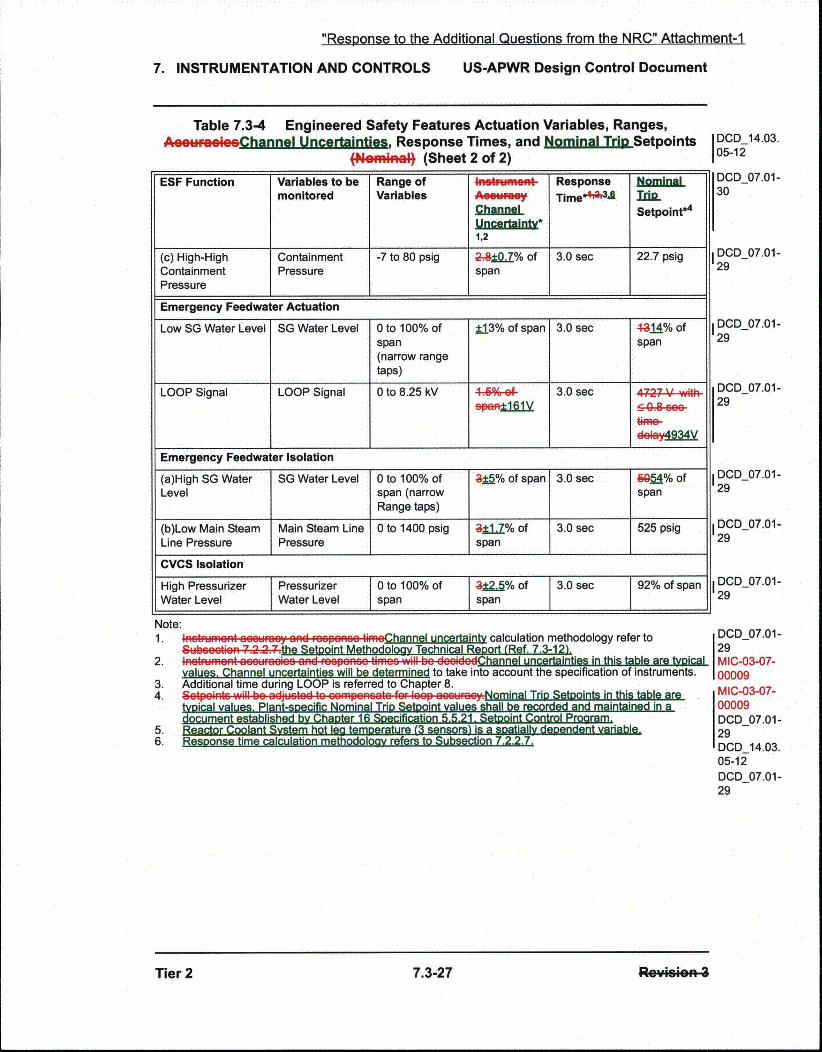
Table 7.3-4 Engineered Safety Features Actuation Variables, Ranges,AcssuFrooiChannel Uncertainties, Response Times, and NgojminjlTriSetpoints
(Nemi•nal (Sheet 2 of 2)DCD_14.03.05-12
ESF Function Variables to bemonitored
Range ofVariables
ChannelUn1,r2ainIX1,2
ResponseTlme*6'23,
NominalIdn.Setpoint*4
(c) High-High Containment -7 to 80 psig 28±1Q0.% of 3.0 sec 22.7 psigContainment Pressure spanPressureEmergency Feedwater Actuation
Low SG Water Level SG Water Level 0 to 100% of ±13% of span 3.0 sec 4-14% ofspan span(narrow rangetaps)
LOOP Signal LOOP Signal 0 to 8.25 kV 44%of- 3.0 sec 4727 V- Awi'th• 9~.9 AAR-
Emergency Feedwater Isolation
(a)High SG Water SG Water Level 0 to 100% of ,05.% of span 3.0 sec 6gQ5a% ofLevel span (narrow span
Range taps)
(b)Low Main Steam Main Steam Line 0 to 1400 psig ±1_.Z% of 3.0 sec 525 psigLine Pressure Pressure span
CVCS Isolation
High Pressurizer Pressurizer 0 to 100% of 312&% of 3.0 sec 92% of spanWater Level Water Level span span
DCD_07.01-30
DCD 07.01-29
DCD_07.01-29
DCD_07.01-29
DCD_07.01-29
DCD_07.01-29
DCD_07.01-29
DCD_07.01-29MIC-03-07-00009MIC-03-07-00009DCD_07.01-29DCD_14.03.05-12DCD_07.01-29
Note:1. nat.r-mont ROM•..u' -and rspenoo ,imzChannel uncertainty calculation methodology refer to
_"_bczt_.n 7.2.2....the Setooint Methodoloav Technical Reoort (Ref. 7.3-12' .2.
3.4.
5.6.
'.nrmr rmnnnr808-8 O-- FOO Pnn. nnr,-n- _- .... .Uflu-:•cenIlnus in Inl s TaDI8 ArA Vio_,al
values. Channel uncertainties will be determined to take into account the specification of instruments.Additional time during LOOP is referred to Chapter 8.SGaetoontc .I.. be adi..t.d to eemp... for 88p .. m......Nominal Trin Setgoints in this table aretvninal vnhi"P Plant-.nAerifir Nnminal Trin 5Retnnint valueq shall he recorded and maintained in a

"Response to the Additional Questions from the NRC" Attachment-1
7. INSTRUMENTATION AND CONTROLS US-APWR Design Control Document
Table 7.8-6 Diverse Actuation Variables, Ranges, AsurueoeoeChannelUncertainties, and NominL cipSetpoints fNf)minel
Diverse Actuation Variables to Range of Variables inetftme& Time NominalFunction be monitored Channel Delay_. TdL
Isme Setpoint*3
uQwntainv*l__,2
Reactor Trip, Turbine Trip, and MFW Isolation
Low Pressurizer Pressurizer 1700 to 2500 psig 2-4120/% of 10 sec 1825 psigPressure Pressure span
High Pressurizer Pressurizer 1700 to 2500 psig 2..3% of span 10 sec 2425 psigPressure Pressure
Low SG Water Level SG Water 0 to 100% of span ,3=2% of span 10 sec 7% of spanLevel (narrow range taps)
Emergency Feedwater Actuation
Low SG Water Level SG Water 0 to 100% of span ;13..2% of span 4Qee 7% of spanLevel (narrow range taps) 10/150
Low-Low Pre ssu rizer 1700 to 2500 osio 3.2 o 120san 1725 QsioPressure Pressure I I
DCD_07.01-29
DCD_07.08-17
DCD_07.08-17
MIC-03-07-00005
DCD_07.01-29MIC-03-07-00009
MIC-03-07-00005DCD_07.08-17
Note:1.
2.
3.
4.5.
'..Intmo!. t ozy•.". Channel uncertainty calculation methodology refer to the Setooint MethodologvTechnical Re-ort (Reference 7. 8-9-.e"t tr.i•i vl7.2t2.tC
IFI~~t~~dF..... 89US•S Wil"b dei hann~l "nr~rtaintins in this table are tYnical values. Channel
uncertainties will be determined to take into account the specification of instruments._94naln"s. W-'- __-_ _-_ -_ .1 -. --- 88 ._; . n 'n - "_m-Nnminal Trin Setnointn in this table are
tical values . Pla nt-specific Nominal TrJio Setnoint values•'shall be recorded and maintained in adocument established by Chaoter 16 Specification 5.5.21. Setooint Control Program.The two time delays are for the turbine-driven and motor-driven EFW oumDS. resoectivelv.The value in "Time Delay" is for the variable timer delay in the DAS.
Tier 2 7.8-15
Re~ol.n4Tier 2 7.8-15 RaWcoan 2