Embed Size (px)
Citation preview

Dynamic Analysis of the Coupled RCL-R/B-PCCV-CIS Lumped Mass Stick Model MUAP-08005 (R0)
Mitsubishi Heavy Industries, LTD.
Dynamic Analysis of the Coupled
RCL-R/B-PCCV-CIS Lumped Mass Stick Model
April 2008
Ⓒ2008 Mitsubishi Heavy Industries, Ltd. All Rights Reserved
Dynamic Analysis of the Coupled RCL-R/B-PCCV-CIS Lumped Mass Stick Model MUAP-08005 (R0)
Mitsubishi Heavy Industries, LTD.
Revision History Revision Page Description
0
All
Original Issue

Dynamic Analysis of the Coupled RCL-R/B-PCCV-CIS Lumped Mass Stick Model MUAP-08005 (R0)
Mitsubishi Heavy Industries, LTD.
Ⓒ 2008 MITSUBISHI HEAVY INDUSTRIES, LTD.
All Rights Reserved
This document has been prepared by Mitsubishi Heavy Industries, Ltd. (“MHI”) in connection with the U.S. Nuclear Regulatory Commission’s (“NRC”) licensing review of MHI’s US-APWR nuclear power plant design. No right to disclose, use or copy any of the information in this document, other that by the NRC and its contractors in support of the licensing review of the US-APWR, is authorized without the express written permission of MHI.
This document contains technology information and intellectual property relating to the US-APWR and it is delivered to the NRC on the express condition that it not be disclosed, copied or reproduced in whole or in part, or used for the benefit of anyone other than MHI without the express written permission of MHI, except as set forth in the previous paragraph.
This document is protected by the laws of Japan, U.S. copyright law, international treaties and conventions, and the applicable laws of any country where it is being used.
Mitsubishi Heavy Industries, Ltd. 16-5, Konan 2-chome, Minato-ku
Tokyo 108-8215 Japan
Dynamic Analysis of the Coupled RCL-R/B-PCCV-CIS Lumped Mass Stick Model MUAP-08005 (R0)
Mitsubishi Heavy Industries, LTD.
Abstract
The purpose of this technical report is to present the dynamic seismic analysis of the coupled system including the Reactor Coolant Loop (RCL), Reactor Building (R/B), Prestressed Concrete Containment Vessel (PCCV) and Containment Internal Structure (CIS).
This report describes the development of the coupled model, modeling method and assumptions, the analysis approach, and the following analysis results:
• Frequencies and mode shapes of the dominant modes
• Acceleration and displacement responses of the structures
• Forces and moments in selected building structures
• In-structure floor response spectra
Dynamic Analysis of the Coupled RCL-R/B-PCCV-CIS Lumped Mass Stick Model MUAP-08005 (R0)
Mitsubishi Heavy Industries, LTD. i
Table of Contents List of Tables iii List of Figures iv List of Acronyms v 1.0 INTRODUCTION 1-1 2.0 DESCRIPTION OF REACTOR BUILDING AND REACTOR COOLANT
LOOP 2-1
2.1 Reactor Building Complex 2-1 2.2 Reactor Coolant Loop 2-1 3.0 US-APWR DCD BASIS 3-1 3.1 Seismic Input 3-1 3.2 Analytical Model 3-1 3.3 Seismic Analysis Method 3-1 3.4 Results of Seismic Analysis – ISRS and Equivalent Static
Acceleration 3-2
3.5 Equivalent Static Analysis 3-2 4.0 APPROACH TO SEISMIC EVALUATION OF COUPLED RCL-R/B-PCCV-CIS
MODEL 4-1
4.1 Modeling Criteria for Building and RCL 4-1 4.2 Consideration of Foundation Compliance 4-1 4.3 Consideration of Variable Element Damping 4-1 4.4 Analysis Approach and Objectives 4-1 5.0 SEISMIC INPUT 5-1 5.1 Design Response Spectra 5-1 5.2 Spectra Compatible Time Histories 5-1 5.3 Relationship of Design Spectra to GMRS 5-1 6.0 COUPLED ANALYTICAL MODEL 6-1 6.1 Building Stick Model Development 6-1 6.2 Development of RCL Model 6-1 6.3 Representation of Foundation Soils Stiffness and Damping 6-2 6.4 Verification of Model – Static and Dynamic Characteristics 6-3

Dynamic Analysis of the Coupled RCL-R/B-PCCV-CIS Lumped Mass Stick Model MUAP-08005 (R0)
Mitsubishi Heavy Industries, LTD. ii
Table of Contents (Cont’d)
7.0 SEISMIC TIME HISTORY ANALYSIS 7-1 7.1 Analysis Method 7-1 8.0 SEISMIC ANALYSIS RESULTS 8-1 8.1 Acceleration and Displacement Responses for Different Soil
Subgrade Conditions 8-1
8.2 Forces and Moments of Building 8-1 8.3 Comparison of ISRS for Different Soil Subgrade 8-2 9.0 CONCLUSION 9-1 10.0 REFERENCES 10-1
Dynamic Analysis of the Coupled RCL-R/B-PCCV-CIS Lumped Mass Stick Model MUAP-08005 (R0)
Mitsubishi Heavy Industries, LTD. iii
List of Tables Table 6-1 Concentrated Mass of Stick Model for Buildings 11-1 Table 6-2 Element Properties of Stick Model for Buildings 11-3 Table 6-3 Material Properties and Damping Value for Buildings 11-4 Table 6-4 Other Spring Connections and Damping Value of Buildings 11-5 Table 6-5(1) Concentrated Mass of RV Model 11-6 Table 6-5(2) Concentrated Mass of SG Model 11-6 Table 6-5(3) Concentrated Mass of RCP Model 11-7 Table 6-5(4) Concentrated Mass of MCP Model 11-7 Table 6-6(1) Material Properties of RV Stick Model 11-8 Table 6-6(2) Element Properties of RV Stick Model 11-8 Table 6-6(3) Element Properties of SG Stick Model 11-9 Table 6-6(4) Material Properties of RCP Stick Model 11-9 Table 6-6(5) Element Properties of RCP Stick Model 11-10 Table 6-6(6) Specification of MCP Model 11-10 Table 6-7 Support Stiffness of RV, SG and RCP 11-11 Table 6-8 Node Connectivity between RCL and CIS 11-12 Table 6-9 Soil Spring Constants and Damping Coefficients 11-13 Table 8-1
(Sheet 1 to 2) Modal Properties of R/B Lumped Mass Stick Model (Fixed Base)
11-14
Table 8-2 Modal Properties of PCCV Lumped Mass Stick Model (Fixed Base)
11-16
Table 8-3 (Sheet 1 to 3)
Modal Properties of CIS and RCL Model (Fixed Base) 11-17
Table 8-4 Modal Properties of Coupled RCL-R/B-PCCV-CIS SSI Model 11-20 Table 8-5 Maximum Accelerations - Coupled RCL-R/B-PCCV-CIS Model,
Soil Subgrade (Vs=1,000 ft/s) 11-21
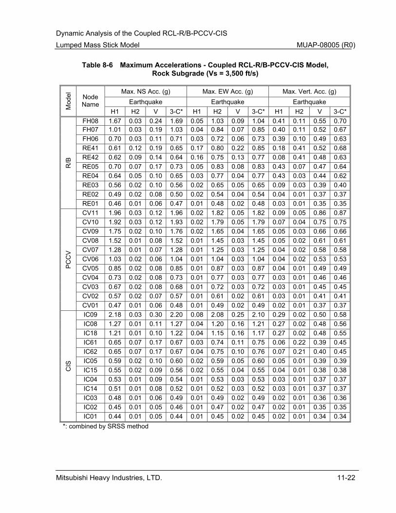
Table 8-6 Maximum Accelerations - Coupled RCL-R/B-PCCV-CIS Model, Rock Subgrade (Vs=3,500 ft/s)
11-22
Table 8-7 Maximum Accelerations - Coupled RCL-R/B-PCCV-CIS Model, Rock Subgrade (Vs=6,500 ft/s)
11-23
Table 8-8 Maximum Accelerations - Coupled RCL-R/B-PCCV-CIS Model, Hard Rock Subgrade (Vs=8,000 ft/s)
11-24
Table 8-9 Model Forces and Moment - Coupled RCL-R/B-PCCV-CIS Model 11-25 Table 8-10 Model Design Forces - R/B-PCCV-CIS Model 11-26 Table 8-11 Maximum Displacements - Coupled RCL-R/B-PCCV-CIS
Model, Soil Subgrade (Vs=1,000 ft/s) 11-27
Table 8-12 Maximum Displacements - Coupled RCL-R/B-PCCV-CIS Model, Rock Subgrade (Vs=3,500 ft/s)
11-28
Table 8-13 Maximum Displacements - Coupled RCL-R/B-PCCV-CIS Model, Rock Subgrade (Vs=6,500 ft/s)
11-29
Table 8-14 Maximum Displacements - Coupled RCL-R/B-PCCV-CIS Model, Hard Rock Subgrade (Vs=8,000 ft/s)
11-30

Dynamic Analysis of the Coupled RCL-R/B-PCCV-CIS Lumped Mass Stick Model MUAP-08005 (R0)
Mitsubishi Heavy Industries, LTD. iv
List of Figures Figure 2-1 US-APWR Plan of R/B Complex at Operating Floor Level 12-1 Figure 2-2 US-APWR Cross Section of R/B 12-1 Figure 2-3 US-APWR Reactor Coolant Loop 12-2 Figure 3-1 Lumped Mass Stick Model for Buildings (R/B, PCCV, CIS) 12-3 Figure 5-1 US-APWR Horizontal CSDRS 12-4 Figure 5-2 US-APWR Vertical CSDRS 12-5 Figure 5-3 Artificial Time Histories Plots (H1) 12-6 Figure 5-4 Artificial Time Histories Plots (H2) 12-7 Figure 5-5 Artificial Time Histories Plots (V) 12-8 Figure 6-1
(Sheet 1 to 3) Lumped Mass Stick Model for Buildings(R/B, PCCV, CIS)
12-9 Figure 6-2 Stick Mass Spring Model for Reactor Coolant Loop 12-12 Figure 6-3 Coupled Stick Mass Model for Reactor Coolant Loop and
Buildings 12-13
Figure 6-4 Connectivity between RCL and Buildings 12-14 Figure 6-5 Stick Mass Model for RV with Internals 12-15 Figure 6-6 Stick Mass Model for SG with Internals 12-16 Figure 6-7 Stick Mass Model for RCP with Internals 12-17 Figure 6-8 Reactor Coolant Loop Piping Model 12-18 Figure 6-9 RV Support and FE Structural Model 12-19 Figure 6-10 Configuration of RV Support 12-20 Figure 6-11 Spring Model of SG Upper Shell Support 12-21 Figure 6-12 Spring Model of SG Intermediate Shell Support 12-22 Figure 6-13 SG Lower Support and RCP Tie Rod 12-23 Figure 6-14 Configuration of SG Lower Supports and RCP Supports 12-24 Figure 8-1 (Sheet 1 to 33)
ISRS of PCCV, CIS, R/B (NS-Direction) 12-25
Figure 8-2 (Sheet 1 to 33)
ISRS of PCCV, CIS, R/B (EW-Direction) 12-42
Figure 8-3 (Sheet 1 to 33)
ISRS of PCCV, CIS, R/B (Vertical-Direction) 12-59

Dynamic Analysis of the Coupled RCL-R/B-PCCV-CIS Lumped Mass Stick Model MUAP-08005 (R0)
Mitsubishi Heavy Industries, LTD. v
List of Acronyms The following list defines the acronyms used in this document. ASCE American Society of Civil Engineers ASME American Society of Mechanical Engineers CEUS central and eastern United States CIS containment internal structure CSDRS certified seismic design response spectra DCD design control document DOF degree of freedom EW east and west FE finite element FIRS foundation input response spectra GMRS ground motion response spectra ISRS in-structure response spectra MCP main coolant piping NS north and south PCCV prestressed concrete containment vessel PGA peak ground acceleration R/B reactor building RCL reactor coolant loop RCP reactor coolant pump RG Regulatory Guide RV reactor vessel RWSP refueling water storage pit SG steam generator SRP Standard Review Plan SRSS square root sum of the squares SSC structure, system and component SSE safe shutdown earthquake SSI soil-structure interaction

Dynamic Analysis of the Coupled RCL-R/B-PCCV-CIS Lumped Mass Stick Model MUAP-08005 (R0)
Mitsubishi Heavy Industries, LTD. 1-1
1.0 INTRODUCTION
This report describes the seismic analysis of the US-APWR reactor building (R/B) and internals coupled with the reactor coolant loops (RCL). With reference to Subsection 3.7.2 and Appendix 3H of the US-APWR design control document (DCD), this report updates the in-structure response spectra (ISRS) and the seismic response of the R/B.
The seismic analysis of the R/B referenced in Subsection 3.7.2 of the US-APWR DCD is based on an analytical model of the structure and does not represent the effects of the stiffness of the RCL on the seismic response, considering RCL as additional masses of the corresponding structural nodes. Because the mass and stiffness of the RCL structure in the normal operating conditions are relatively significant, the RCL structure and the building structures may introduce dynamic interaction (coupling) and consequently affect the seismic response of both. This report develops the coupled RCL-R/B- prestressed concrete containment vessel (PCCV) - containment internal structure (CIS) model and documents the resulting seismic response utilizing the same seismic input ground motion and foundation medium as in the US-APWR DCD.
Section 2.0 of the report briefly describes the R/B structure and the RCL. The US-APWR DCD basis is presented in Section 3.0. Sections 4.0 through 8.0 refer to the details of the coupled model analysis. Section 4.0 presents the overall analytical approach. Section 5.0 identifies the seismic input considered in the present analysis. The details of the coupled model are presented in Section 6.0. Sections 7.0 and 8.0 include the method of the time history seismic analysis and the results of the analysis, respectively. Finally, Section 9.0 contains concluding remarks.

Dynamic analysis of the Coupled RCL-R/B-PCCV-CIS Lumped Mass Stick Model MUAP-08005 (R0)
Mitsubishi Heavy Industries, LTD. 2-1
2.0 DESCRIPTION OF REACTOR BUILDING AND REACTOR COOLANT LOOP
A common power block foundation basemat supports the R/B as well as PCCV and CIS. This complex of structures includes the following functional areas.
• PCCV and CIS
• Safety system pumps and heat exchangers area
• Fuel handling area
• Main steam and feed water area
• Safety-related electrical area
2.1 Reactor Building Complex
Figure 2-1 presents the plan of the R/B Complex at the operating floor elevation and identifies the above functional areas and Figure 2-2 presents a generalized cross-section through the R/B. The common foundation, located at a depth of 38 feet, 10 inches from plant grade, is approximately 210 feet x 309 feet in plan dimensions and varies in thickness from 9 feet, 11 inches at the edges to 38 feet, 2 inches at the center where the containment structure is located. Although the buildings are supported on the common basemat, they are independent free standing structures above the basemat. The R/B is a five-story reinforced concrete structure extending about 150 feet, 4 inches above the basemat. The R/B structure consists primarily of shear walls and reinforced concrete floor diaphragms. It envelops a free-standing containment at its center.
The PCCV is a vertically oriented cylindrical structure with an inside diameter of 149 feet, 2 inches. It extends from the basemat to an inside height of 226 feet, 5 inches where a 3 feet, 8 inches thick hemispherical dome comprises the roof structure. The vertical cylindrical walls are 4 feet, 4 inches thick and accommodate the equipment hatch and personnel airlocks. The PCCV is circumferentially and vertically pre-stressed with unbonded tendons. The CIS include the refueling water storage pit (RWSP), reactor cavity, refueling cavity, refueling canal, operating deck, polar crane, and major piping, mechanical, and electrical penetrations.
2.2 Reactor Coolant Loop
Figure 2-3 presents a schematic of the US-APWR RCL. The US-APWR is a four loop plant with four safety trains. Each RCL consists of the reactor vessel (RV), the steam generator (SG), the reactor coolant pump (RCP), and the loop piping. The loop piping consists of hot leg, crossover leg and cold leg piping in which the coolant flows from RV to SG, from SG to RCP, and from RCP back to RV, respectively.

Dynamic Analysis of the Coupled RCL-R/B-PCCV-CIS Lumped Mass Stick Model MUAP-08005 (R0)
Mitsubishi Heavy Industries, LTD. 3-1
3.0 US-APWR DCD BASIS
This section summarizes the US-APWR DCD basis for the seismic analysis and the reported seismic response of the R/B Complex. The US-APWR DCD is based on a seismic analysis of the R/B Complex which utilizes an uncoupled analytical model of the structures exclusive of the RCL. In accordance with its commitment made as part of the US-APWR DCD submittal, MHI has updated the analysis and the response results considering the potential dynamic coupling between the R/B and the RCL.
3.1 Seismic Input
The seismic input of ground motion utilized in the analysis of the R/B Complex is represented in the US-APWR DCD as the CSDRS. The CSDRS are sufficiently broad banded and are expected to envelope the seismic design ground motions at a wide range of sites in the central and eastern United States (CEUS). The CSDRS are similar to the standard shapes of the Regulatory Guide (RG) 1.60 (Reference 2) spectra with an enhanced high frequency content anchored to a peak ground acceleration (PGA) of 0.3 g.
3.2 Analytical Model
The seismic design evaluation of the R/B Complex reported in the US-APWR DCD develops a lumped parameter analytical model representing the stiffness and mass characteristics of the R/B Complex. Each of the structures (R/B, PCCV, and CIS) is represented as a lumped mass stick model rigidly connected to the basemat. The locations of the lumped masses relative to the center of the story rigidity account for the effects of mass eccentricities on the seismic response. The RCL is included in this model as nodal masses. However, its stiffness is not explicitly represented. The effects of soil-structure interaction (SSI) are included in the analysis utilizing frequency-independent lumped soil springs and damping. The resulting analytical model represents all six degrees of freedom (DOFs).
The analytical models of the structures are described more fully in Subsection 3.7.2 and Appendix 3H of the US-APWR DCD and are also presented in this report in Section 6.0 which discusses the coupled model for the R/B and the RCL.
The lumped mass stick models are validated by comparing their dynamic characteristics with the dynamic characteristics of detailed finite element (FE) models of the respective buildings, which are also utilized to develop internal forces and moments in the structural components. The FE model combines the R/B, PCCV, and CIS on their common basemat as described in Appendix 3H of the US-APWR DCD.
3.3 Seismic Analysis Method
The site-independent seismic design of the R/B Complex uses a lumped parameter representation to model the interaction of seismic category I structures with the supporting media. The lumped parameter model considers a rigid basemat resting on the surface of a uniform elastic-half-space. Six sets of two parameters, one for stiffness and one for damping, are developed in accordance with Subsection 3.3.4.2 of ASCE 4-98 (Reference 3) to represent the properties of the SSI in each one of the six DOFs that describe the three-dimensional vibrations of the rigid foundation.
Dynamic Analysis of the Coupled RCL-R/B-PCCV-CIS Lumped Mass Stick Model MUAP-08005 (R0)
Mitsubishi Heavy Industries, LTD. 3-2
Seismic analysis of the uncoupled models of the R/B Complex of structures as well as the RCL utilizes the direct integration of the equations of motion. In addition to typical stiffness and mass matrices, the equations of motion incorporate a full damping matrix developed on the basis of stiffness proportional modal damping ratios. The direct integration of equations develops the dynamic response at all dynamic DOF in terms of peak accelerations, displacements, story shears and moments as well as acceleration time histories for the calculation of ISRS.
3.4 Results of Seismic Analysis – ISRS and Equivalent Static Acceleration
The use of frequency independent SSI impedance is based on the assumption that the subgrade conditions are relatively uniform basemat dimension below the bottom of the basemat of the major seismic category I structure. The following values for shear wave velocity Vs of soil conditions are assumed in order to simplify the analysis;
• Soft soil site (Soft), Vs = 1,000 ft/s
• Rock site (Medium 1), Vs = 3,500 ft/s
• Rock site (Medium 2), Vs = 6,500 ft/s
• Hard rock site (Hard Rock), Vs = 8,000 ft/s
Appendix 3H of the US-APWR DCD presents the results of the uncoupled seismic analysis in terms of the nodal accelerations and displacements and shear force and moments. Appendix 3I of the US-APWR DCD presents ISRS at several elevations of the R/B, PCCV and CIS. These results represent the envelope response based on a range of soil conditions. For the input represented by the ground motion response spectra (GMRS), the peak response acceleration in the horizontal direction varies from 0.3 g at the common basemat to 0.95 g, 2.15 g and 2.85 g at the top of the R/B, PCCV and CIS, respectively. The corresponding maximum displacements and story shears are minimal.
Typical ISRS illustrate the important fundamental modes that determine the dynamic response of the structures. The SSI modes range from 1.33 Hz for the soft soil case to 4.26 Hz for the Medium 2. These modes are evident in the shape of the resulting ISRS. The fundamental modes of the building structures placed on a fixed base range from 5.29 Hz for the R/B to 4.57 Hz for the PCCV. The ISRS also exhibit the contribution of the building modes. Indeed for the fixed base analysis, which envelops the hard rock conditions, the building seismic response and the ISRS illustrate the full contribution of the building modes.
3.5 Equivalent Static Analysis
The results of maximum member forces obtained from the time history analyses serve as basis for development of equivalent static seismic loads for design of the structural members of major seismic category I buildings and structures. Based on the time history analyses, the maximum shear, axial force and moments are developed at each lumped mass node from the response in each orthogonal direction. These forces are subsequently applied as equivalent static loads on the detailed three-dimensional FE model that is developed for computation of internal forces and stresses in the structural members and components of R/B-PCCV-CIS.

Dynamic Analysis of the Coupled RCL-R/B-PCCV-CIS Lumped Mass Stick Model MUAP-08005 (R0)
Mitsubishi Heavy Industries, LTD. 3-3
The full spectrum of the design loads and load combinations are discussed in Section 3.8 of the US-APWR DCD.

Dynamic Analysis of the Coupled RCL-R/B-PCCV-CIS Lumped Mass Stick Model MUAP-08005 (R0)
Mitsubishi Heavy Industries, LTD. 4-1
4.0 APPROACH TO SEISMIC EVALUATION OF COUPLED RCL-R/B-PCCV-CIS MODEL
The technical approach used to evaluate the coupled seismic behavior of the R/B Complex and RCL combines the lumped parameter analytical models developed separately for the R/B Complex of building structures, and the RCL piping and components, reported in the US-APWR DCD. These models are independently validated by comparing the dynamic characteristics with those obtained from the respective full FE models. The integration of the models into one analytical model thus reflects the combined mass and stiffness matrices, which are utilized in the solution of the dynamic equations of motion.
4.1 Modeling Criteria for Building and RCL
The modeling criteria utilized to develop the uncoupled analytical models of the R/B Complex as well as the RCL are presented in Appendix 3C and 3H of the US-APWR DCD. These criteria address the development of the parameters of the model such as the lumped masses, member stiffness, centers of mass and centers of vertical and horizontal rigidities of the load carrying elements, etc. Additionally, Appendices 3C and 3H also describe the representation of the damping characteristics in the models and the manner in which variable element damping is incorporated into the dynamic analysis. Both the R/B Complex and the RCL are represented by an adequate number of DOF to represent significant modes in the range of frequencies up to 50 Hz.
The Standard Review Plan (SRP) coupling criteria is applied because the subsystem such as the RCL spans several locations of the building and is characterized by several significant frequencies and participating masses. It is judged that the RCL may interact dynamically with the R/B Complex of structures. Based on experience, the ISRS developed from the coupled models is more representative than those from uncoupled models. Any interaction of modes that may affect the calculated frequency content of the support motion is properly accounted for.
4.2 Consideration of Foundation Compliance
Because the RCL is entirely enclosed in the R/B Complex, its presence in the model is not expected to affect the representation of the SSI. Accordingly, as in the case of the uncoupled building model, the coupled analysis represents the foundation medium by lumped soil springs and dashpots. The lumped parameters of the foundation soils are based on the foundation mat dimensions, and on presumed strain dependent shear modulus of a uniform subgrade.
4.3 Consideration of Variable Element Damping
The coupled analytical model includes concrete elements, structural steel elements and piping and components of the RCL in addition to the basemat soil compliance elements. Each of these element categories is characterized by different damping values. As documented in Appendix 3C and 3H of the US-APWR DCD the element damping values utilized in the seismic analysis of the uncoupled models are 3% for the RCL, 7% for the reinforced concrete structures, 5% for the prestressed concrete structures, 5% for Steal-Concrete Modules.
4.4 Analysis Approach and Objectives
The primary objective of the coupled analysis is to develop certified ISRS considering the

Dynamic Analysis of the Coupled RCL-R/B-PCCV-CIS Lumped Mass Stick Model MUAP-08005 (R0)
Mitsubishi Heavy Industries, LTD. 4-2
effects of dynamic coupling between the R/B Complex and the RCL. The ISRS resulting from this report analysis and reported in Section 8.0 would be utilized to compare with site-specific ISRS by referencing the US-APWR DCD. A single set of time histories compatible with the CSDRS representing the design ground motions are considered to be adequate for use in the direct integration of the coupled equations of motion. As demonstrated in the US-APWR DCD, the set of time histories considered are compatible with the CSDRS at the bottom of basemat level and are of adequate duration and frequency content. It is expected that the ground motion time histories reasonably capture a wide range of typical site conditions in the CEUS.
Dynamic Analysis of the Coupled RCL-R/B-PCCV-CIS Lumped Mass Stick Model MUAP-08005 (R0)
Mitsubishi Heavy Industries, LTD. 5-1
5.0 SEISMIC INPUT
The seismic inputs utilized in the analysis of the couple model are identical with those reported in the US-APWR DCD. For completeness of this report, the following sections present the design response spectra and the time histories used in the coupled model seismic analysis.
5.1 Design Response Spectra
Figures 5-1 and 5-2 present the CSDRS representing the seismic ground motion utilized in the seismic design of the US-APWR SSCs. These spectra define the ground motion at the free-field outcrop at the bottom of the building basemat.
The horizontal and vertical CSDRS shown respectively on Figures 5-1 and 5-2 are based on the RG1.60 shapes anchored to 0.3g PGA. In order to account for the expected higher frequency content of seismic ground motion in the CEUS, that is conservatively enhanced to extend the amplified acceleration of the RG 1.60 shapes.
5.2 Spectra Compatible Time Histories
A set of three statistically independent acceleration time histories is synthesized artificially for use as the input motion in the seismic response analysis of the R/B Complex reported in the US-APWR DCD. These time histories are compatible with the CSDRS and satisfy the matching requirements of Section II of SRP 3.7.1 (Reference 5). The time histories are about 20 second duration and are digitized at 0.005 seconds. Figures 5-3 through 5-5 present the acceleration, velocity and displacement time histories used in the seismic analysis. The correlation coefficient between any two time histories is less than 0.16.
5.3 Relationship of Design Spectra to GMRS
The seismic analysis reported here applies the time histories above motion at the fixed ends of the soil springs representing the medium of foundation. Accordingly, the CSDRS are taken to represent the ground motion at the bottom of the basemat and in the free field. In order to achieve consistency for comparing the site-specific response to the standard plant response, the FIRS is to also represent the seismic ground motion at the bottom of basemat in the free field. If embedment soils above the foundation level are considered in the site-specific SSI analysis, then the strain compatible properties for these soils are to be consistent with the manner in which the GMRS and the respective FIRS are developed.
Dynamic Analysis of the Coupled RCL-R/B-PCCV-CIS Lumped Mass Stick Model MUAP-08005 (R0)
Mitsubishi Heavy Industries, LTD. 6-1
6.0 COUPLED ANALYTICAL MODEL
Based on the decoupling criteria of SRP 3.7.2 (Reference 6), the subsystems and components inside containment, with the exception of the RCL are included in the coupled model by lumped masses placed at appropriate node locations. The RCL and the associated major components, on the other hand, are incorporated into the coupled model as a lumped parameter model representing the geometry of the RCL, and connected at appropriate locations of the CIS.
The following sections briefly describe the details of the building models and the RCL model.
6.1 Building Stick Model Development
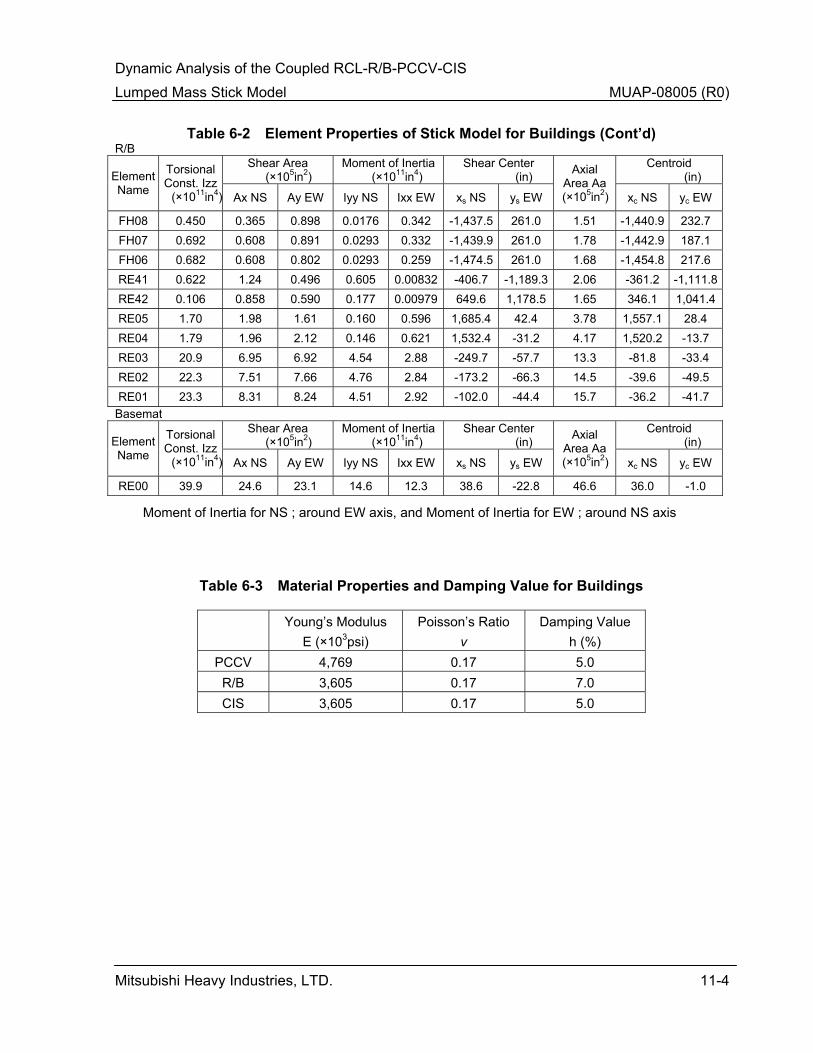
Figure 6-1 presents the lumped mass stick models of the R/B, PCCV, and the CIS. The lumped mass models are developed on the basis of the building structural configuration and represent the centers of mass and the centers of rigidity. The lumped mass models of the individual buildings are rigidly connected to each other at the basemat and appropriate floor levels. The complete model shown in Figure 6-1 is validated by comparing its dynamic characteristics with those obtained from detailed FE model of the R/B Complex. Tables 6-1 and 6-2 present the values of the lumped masses and the element properties of the connecting story stiffnesses such as the cross sectional areas, shear areas and moment of inertia. Additionally, Table 6-3 presents the material properties used to develop the story stiffnesses and the material damping of the structural elements. As shown in Figure 6-1 (sheets 1 of 3), the CIS is represented by a single stick below the operating floor at elevation 76 feet, 5 inches. Above this elevation the CIS is represented by three sticks located at the pressurizer, and the SG compartments. At the elevation of the pressurizer lower support, the internal structure’s common floor is represented by spring elements connecting nodes IC07 and IC05. Table 6-4 presents the stiffness of these spring elements. Similarly, the R/B nodes RE41, RE42 and RE04 are connected by rigid links representing the floor at elevation 101.00 feet. Figure 6-1 (Sheet 2 of 3 and 3 of 3) illustrates this configuration and Table 6-4 presents the spring connections and damping values. Figure 6-1 (Sheet 2 of 3 and 3 of 3) also show two sticks representing the stiffness of each story of the R/B. The vertical stiffness of the story is represented by a truss element, while the horizontal and bending stiffness are represented by beam elements.
6.2 Development of RCL Model
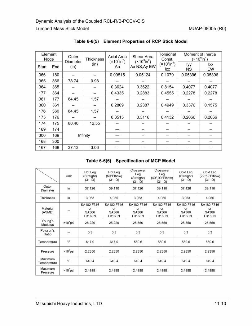
The RCL analysis model consists of RV, SG, RCP, main coolant piping (MCP), and component supports, as applicable, for each loop. The RCL piping and support system is modeled as three-dimensional FEs representing the components, pipes, and supports as beam elements, masses, and springs with imposed boundary conditions.
The RCL of the US–APWR has four loops, which are modeled as combination of RV, SG, RCP and MCP. These combined system models include both the translational and rotational stiffness, mass characteristics of the RCL piping and components, and the stiffness of supports. The stiffnesses and mass effects of auxiliary line piping are considered when they affect the system. The analytical models of the individual components of the RCL such as the RV, the SG and RCP and MCP are presented respectively on Figures 6-5, 6-6, 6-7 and 6-8, and Tables 6-5, 6-6 and 6-7 present the mass, material properties and stiffness characteristics of the components.
Dynamic Analysis of the Coupled RCL-R/B-PCCV-CIS Lumped Mass Stick Model MUAP-08005 (R0)
Mitsubishi Heavy Industries, LTD. 6-2
The RV support system consists of eight steel support pads which are integrated with the inlet and outlet nozzle forgings. The support pads are placed on brackets, which are supported by an embedded steel structure on the primary shield wall at elevation 35 feet, 7.25 inches. The supports allow radial thermal growth of the RCS and RV. Details of the RV supports and their relationship with the primary shield wall are presented in Section 3.8 of the US-APWR DCD. Figure 6-9 presents the RV support configuration and the FE model of the support ring utilized to obtain the support stiffness coefficients. As shown in Figure 6-10, each support point is represented by tangential and vertical springs.
The SG support system consists of an upper shell support structure at centerline elevation 96 feet, 7 inches, an intermediate shell support structure at centerline elevation 75 feet, 5 inches, and a lower support structure at centerline elevation 45 feet, 7.64 inches. The upper and intermediate shell supports are lateral restraints (snubbers) attached to structural steel brackets, while the lower support structure is constructed entirely of structural steel and provides both vertical and lateral support. Four pinned-end columns to the slab at elevation 25 feet, 3 inches support the vertical loads of the SG. Each RCP support system consists of a lateral support structure at centerline elevation 42 feet, 7.3 inches, and three pinned-end structural columns to the slab at elevation 25 feet, 3 inches. Both support structure are designed considering thermal expansion of connected piping.
Figures 6-11 and 6-12 present the FE models utilized to develop the support stiffnesses of the upper and intermediate shell supports of the SGs. The lower support system at the base of each SG, shown for example in Figure 6-13, consists of compression only restraints oriented in the tangential and radial directions with respect of RV center. Although each support system is therefore nonlinear, the overall combined supports of the four loops is linearized by incorporating tension-compression springs in the tangential direction at all four SGs, and tension-compression springs in the radial direction are incorporated at the SGs of loops C and D. The SGs associated with loops A and B which are located diametrically opposite do not include the radial restraints. Figure 6-14 presents the overall analytical representation of the lower support structure of the SG. Figure 6-14 also shows the RCP tie rod representation.
Figure 6-2 presents the analytical model of the entire RCL including the individual components of the four loops and the support representation. This model is connected to the building model by attaching the support springs of the RCL to the appropriate building nodes to result in a coupled model shown in Figure 6-3. Figure 6-4 and Table 6-8 identify the connectivity between the RCL nodes and the building nodes. Typically, the fixed end nodes of the RCL support springs are attached to the nodes associated with the internal concrete by rigid links. For example, nodes 2601, 2602, 2603 and 2604 which represent the ends of the RV support springs at the RV inlet and outlet nozzle are all connected by rigid links to IC03 of the CIS at that elevation.
6.3 Representation of Foundation Soils Stiffness and Damping
As described in the US-APWR DCD for the uncoupled model, the SSI analysis of the coupled model also utilizes lumped foundation soil compliance. Accordingly, the site-independent SSI analyses of the coupled model assume a rigid basemat resting on uniform linear-elastic half-space. The SSI stiffness and damping are incorporated in the model as frequency-independent lumped parameters that describe the stiffness of the foundation medium and the dissipation of energy in the SSI system in the six DOFs. The lumped parameters of the SSI are calculated based on the recommendations of ASCE 4-98

Dynamic Analysis of the Coupled RCL-R/B-PCCV-CIS Lumped Mass Stick Model MUAP-08005 (R0)
Mitsubishi Heavy Industries, LTD. 6-3
(Reference 3). The values of the lumped SSI damping in two horizontal translational DOFs are conservatively set at 60% of the theoretical dashpot values based on ASCE 4-98 (Reference 3).
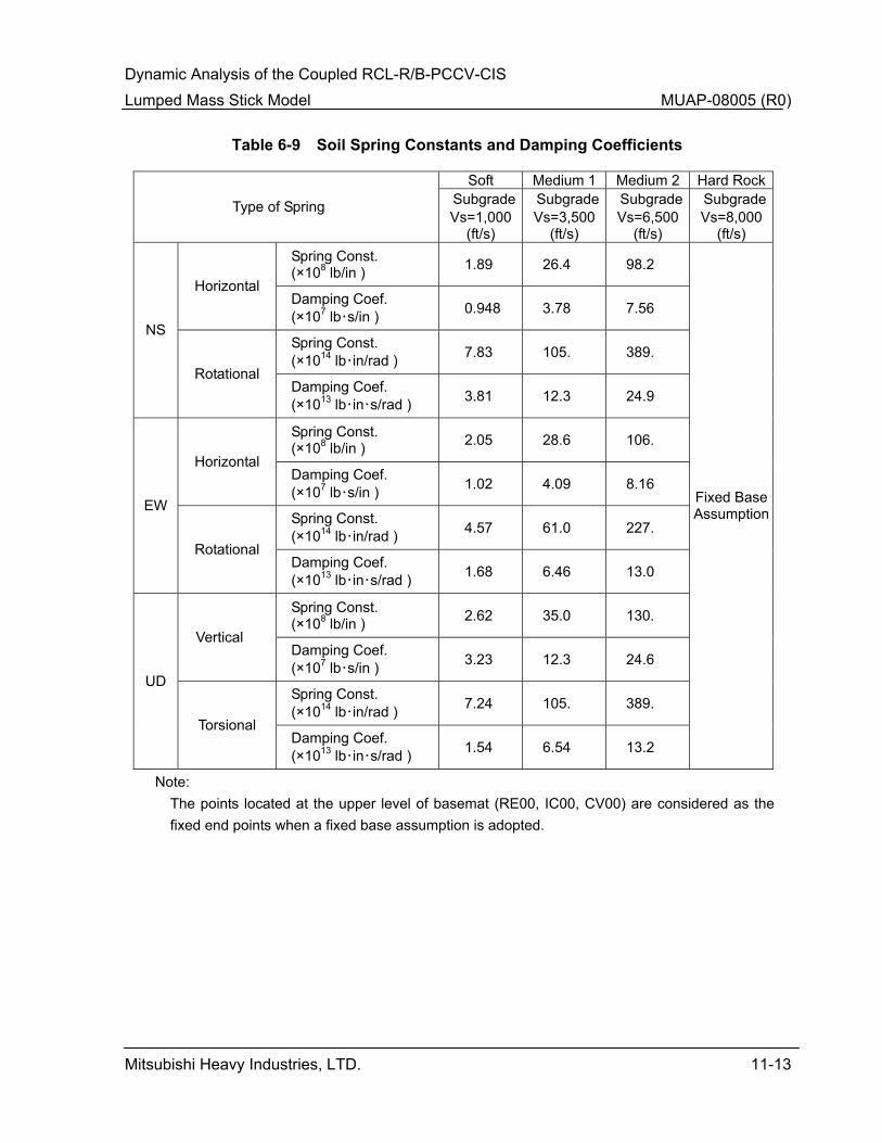
The use of frequency independent SSI impedance parameters is based on the assumption that the subgrade conditions are relatively uniform corresponding to the basemat dimensions. Table 6-9 presents the lumped foundation soil stiffness and damping and illustrates the range of soil parameters included in the seismic design analysis of the standard plant.
6.4 Verification of Model – Static and Dynamic Characteristics
The lumped mass stick models were verified by comparing their static and dynamic response to the static and dynamic response from FE models of the respective structures. A static load analysis as described in the following steps verified that the stiffness properties of the stick models were consistent with the FE model:
(i) A FE model consisting of the portion of the building above the upper level of the basemat, considering the walls, columns, and floor slabs, is developed using brick, shell, and beam elements.
(ii) By fixing the upper level of the basemat, a set of vertically distributed horizontal loads, which is established considering the earthquake excitation, is applied at each of the main floor levels of the FE model and the resulting horizontal displacements are evaluated at the top level of each floor.
(iii) The same analysis as described above in (ii) is performed on the seismic stick model and the set of vertically distributed horizontal displacements from the stick model analysis is compared with that obtained from the analysis of the FE model.
(iv) If the difference of displacement distribution between the FE model and the seismic stick model is considered to be large, the stiffness properties of the stick model are adjusted so that the difference sufficiently small.
The stick model stiffness properties that were adjusted through the above procedure are as follows:
• The flange width of the seismic walls of north and south (NS) direction under the operation floor level is reduced from H/3 to H/6 (H: total height of the wall).
• The flange widths of the seismic walls above the operation floor are not taken into account.
• The shape factor (=1.2) is taken into account for the seismic walls in the NS direction above the operation floor, except for the fuel handling area of the R/B.
Similarly, the dynamic behavior of the stick models was verified by comparing the seismic response to that obtained from the detailed FE model.
The 5% damping ISRS are calculated at several arbitrarily selected node points in the lumped mass stick model that represent main floor levels. The ISRS derived for those node points in
Dynamic Analysis of the Coupled RCL-R/B-PCCV-CIS Lumped Mass Stick Model MUAP-08005 (R0)
Mitsubishi Heavy Industries, LTD. 6-4
the lumped mass stick model are then compared with ISRS developed for the corresponding locations in the FE model. Details of the FE models of the respective buildings are presented in Appendix 3H of the US-APWR DCD.
Dynamic Analysis of the Coupled RCL-R/B-PCCV-CIS Lumped Mass Stick Model MUAP-08005 (R0)
Mitsubishi Heavy Industries, LTD. 7-1
7.0 SEISMIC TIME HISTORY ANALYSIS
As in the case of the uncoupled analysis, the seismic analysis of the coupled model also utilizes direct integration of the equations of motion. The following paragraphs briefly describe the details of the analysis.
7.1 Analysis Method
Because of different damping in different elements of the model, such as the SSI elements, structural concrete and component steels, the equations of motion are expanded to include the full stiffness, damping and mass matrices. A fully populated damping matrix is developed by matrix transformation utilizing stiffness and mass matrices and the mode shapes.
The resulting equations of motion are solved by direct integration for the three orthogonal seismic ground motion time histories applied separately. The analysis outputs the maximum displacements and accelerations, story shears and moments. Additionally, the analysis also develops the floor response time histories which are subsequently used to compute ISRS.

Dynamic Analysis of the Coupled RCL-R/B-PCCV-CIS Lumped Mass Stick Model MUAP-08005 (R0)
Mitsubishi Heavy Industries, LTD. 8-1
8.0 SEISMIC ANALYSIS RESULTS
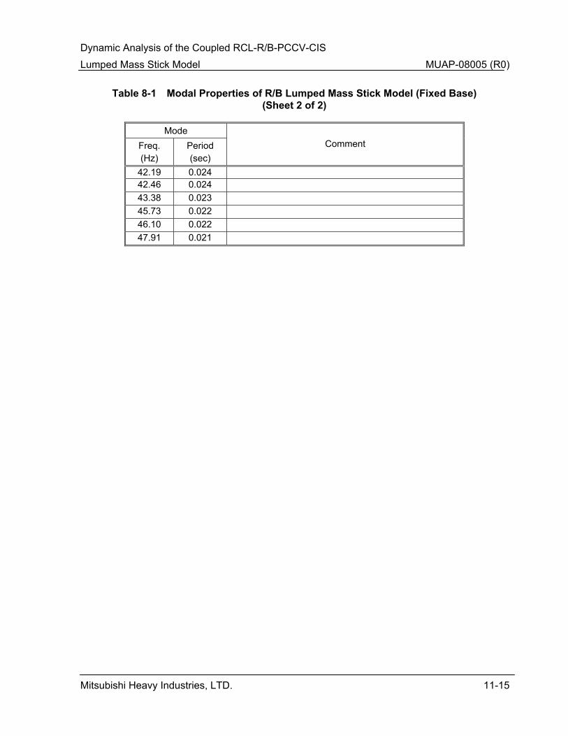
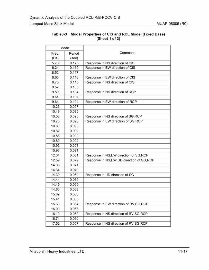
Tables 8-1 through 8-3 present the dynamic characteristics of the individual models of the R/B, PCCV and the coupled RCL-CIS in terms of the modal frequencies and mode shape description. As seen from these tables, the fundamental fixed base modes of the R/B, PCCV and the coupled RCL-CIS models are respectively, 5.3 Hz, 4.6 Hz and 5.7 Hz. These modes exhibit predominantly shear displacement of the concrete structures either in the NS or east and west (EW) directions. Tables 8-1 to 8-3 present all frequencies up to about 50 Hz which are implicitly included in the direct integration time history analysis.
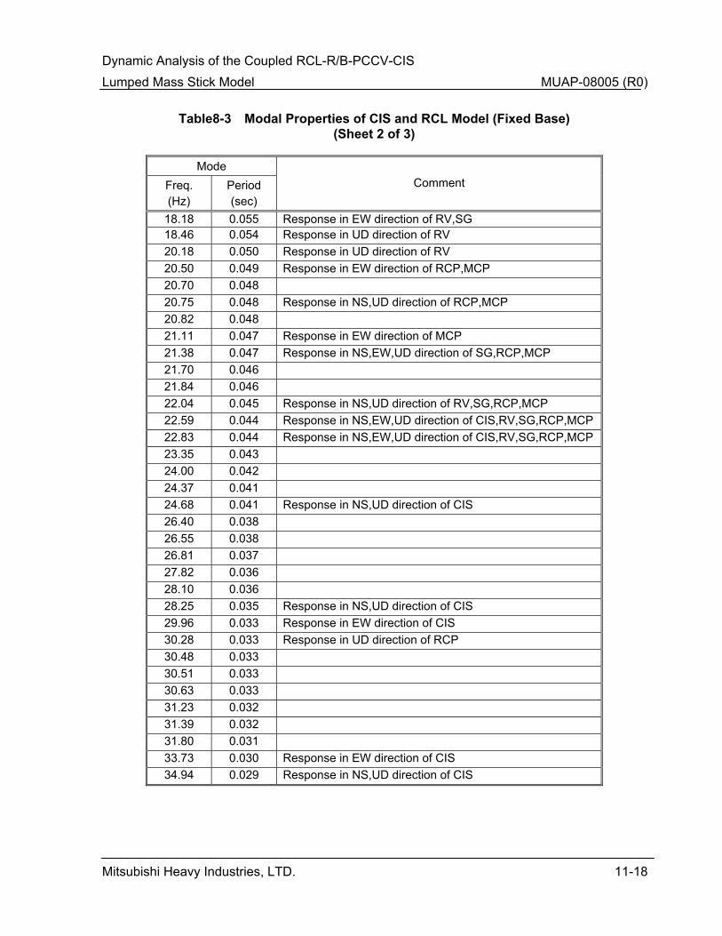
Based on comparing the frequencies in Table 8-3 to those presented in the US-APWR DCD for the uncoupled CIS model, including the RCL does not significantly affect the dynamic characteristics of the CIS. Some of the higher modes of the coupled model are expected to include both the structural components as well as the RCL components. This type of coupling may affect the ISRS at some locations.
Table 8-4 presents the modal characteristics of the entire coupled model of the R/B Complex and the RCL supported on soil springs. The SSI frequencies in the horizontal direction vary from 1.3 Hz to 4.3 Hz. These results suggest that for stiffer soils with shear wave velocities in the range of Vs = 1,000 ft/s to 6,500 ft/s the SSI modes may combine with the structural modes.
8.1 Acceleration and Displacement Responses for Different Soil Subgrade Conditions
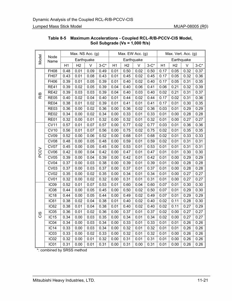
The maximum absolute nodal accelerations (zero period acceleration values) obtained from the direct integration time history analyses of the coupled RCL-R/B-PCCV-CIS model, are presented in Tables 8-5 through 8-8, for the four generic subgrade conditions with soil subgrade (Soft) for Vs = 1,000 ft/s, rock subgrade (Medium 1) for 3,500 ft/s, rock subgrade (Medium 2) 6,500 ft/s, hard rock subgrade (Hard Rock) and 8,000 ft/s, respectively. The tables present the maximum absolute nodal accelerations obtained for each of the three global orthogonal directions of the earthquake input motion as well as the combined maximum absolute nodal accelerations. The accelerations obtained for the earthquake components in the three global orthogonal directions are combined in accordance with RG 1.92 (Reference 7) using the square root sum of the squares (SRSS) method, and presented in the Tables.
The rock subgrade case with a shear wave velocity of 6,500 ft/s exhibits the largest amplification due to the building modes. The peak acceleration response at the top of the structures is similar to the peak response from the uncoupled model.
8.2 Forces and Moments of Building
Table 8-9 presents the floor forces and moment obtained from the time history analyses of the coupled model. Comparing the results in Table 8-9 to the design floor forces of Table 8-10 which is presented in Appendix 3H of US-APWR DCD, it is confirmed that the shear force or moment of any mass node on Table 8-9 is less than or equal to that of the design value on Table 8-10. This confirms that the shear forces and moment calculated from the coupled system seismic analysis are less than those used in design. Tables 8-11 through 8-14 present the response displacements at various locations of the structures. As seen from these tables, the maximum displacements occur for the case of the soft soil subgrade. However, the displacements at the top of the respective buildings relative to the basemat are
Dynamic Analysis of the Coupled RCL-R/B-PCCV-CIS Lumped Mass Stick Model MUAP-08005 (R0)
Mitsubishi Heavy Industries, LTD. 8-2
less than about 1.5 inches.
8.3 Comparison of ISRS for Different Soil Subgrade
Figures 8-1 through 8-3 present three sets of ISRS. Each set includes the ISRS at various elevations of the PCCV, CIS and the R/B structures for all cases of the foundation soil types including the envelop and broadened spectra. Figure 8-1 presents the ISRS in the NS direction, Figure 8-2 the spectra in the EW direction and Figure 8-3 presents the vertical ISRS. The ISRS resulting from the coupled system analysis are similar to those reported in the US-APWR DCD from the uncoupled analyses.
Dynamic Analysis of the Coupled RCL-R/B-PCCV-CIS Lumped Mass Stick Model MUAP-08005 (R0)
Mitsubishi Heavy Industries, LTD. 9-1
9.0 CONCLUSION
This report has presented the development of the coupled model including the R/B, PCCV, CIS and the RCL. It describes the mass, stiffness and damping characteristics of the model, the seismic inputs, the methods of analysis and the resulting seismic response. The seismic response is presented in terms of the accelerations, displacements, inernal forces and moments and the ISRS. These response quantities from the design basis for verifying the standard plant SSCs.
Based on the result of comparing the seismic response of the coupled RCL-R/B-PCCV-CIS model and the uncoupled R/B Complex model given in the US-APWR DCD, the following conclusions are developed:
• No significant differences were observed in the response acceleration, displacement and ISRS results between the coupled RCL-R/B-PCCV-CIS model and the uncoupled R/B Complex model.
• The building design forces defined in the US-APWR DCD have exceeded the forces resulting from the coupled RCL-R/B-PCCV-CIS model. Therefore it has been confirmed that the building design forces defined in the US-APWR DCD are reasonable conservative.

Dynamic Analysis of the Coupled RCL-R/B-PCCV-CIS Lumped Mass Stick Model MUAP-08005 (R0)
Mitsubishi Heavy Industries, LTD. 10-1
10.0 REFERENCES
1. ASME Boiler and Pressure Vessel Code, Section III. American Society of Mechanical Engineers, 2001 Edition including 2003 Addenda.
2. Design Response Spectra for Seismic Design of Nuclear Power Plants, Regulatory Guide 1.60 Rev. 1, U.S. Nuclear Regulatory Commission, Washington, DC, December 1973.
3. Seismic Analysis of Safety Related Nuclear Structure. American Society of Civil Engineers, ASCE 4-98, Reston, Virginia, 2000.
4. A Performance-Based Approach to Define the Site-Specific Earthquake Ground Motion, Regulatory Guide 1.208 Rev. 0, U.S. Nuclear Regulatory Commission, Washington, DC, March 2007.
5. Seismic Design Parameters, Standard Review Plan for the Review of Safety Analysis Report for Nuclear Power Plants, NUREG-0800, SRP 3.7.1, Rev. 3, U.S. Nuclear Regulatory Commission, Washington, DC, March 2007.
6. Seismic System Analysis, Standard Review Plan for the Review of Safety Analysis Report for Nuclear Power Plants, NUREG-0800, SRP 3.7.2, Rev. 3, U.S. Nuclear Regulatory Commission, Washington, DC, March 2007.
7. Combining Responses and Spatial Components in Seismic Response Analysis, Regulatory Guide 1.92 Rev. 2, U.S. Nuclear Regulatory Commission, Washington, DC, July 2006.

Dynamic Analysis of the Coupled RCL-R/B-PCCV-CIS Lumped Mass Stick Model MUAP-08005 (R0)
Mitsubishi Heavy Industries, LTD. 11-1
Table 6-1 Concentrated Mass of Stick Model for Buildings PCCV
Weight (×106lb)
Weight Moment of Inertia (×1012lb・in2)
Mass Center (in) Mass
Name EL. (in)
W Jyy NS
Jxx EW
Jzz Torsional
xg NS
yg EW
CV11 2,762 0.810 0.00685 0.00685 0.0133 0.00 0.00 CV10 2,700 3.88 0.393 0.393 0.766 0.00 0.00 CV09 2,420 7.22 1.94 1.94 3.76 0.00 0.00 CV08 2,077 8.11 3.23 3.23 6.30 0.00 0.00 CV07 1,747 11.6 4.97 4.97 9.82 0.00 0.00 CV06 1,386 8.74 3.79 3.79 7.42 0.00 0.00 CV05 1,106 7.30 3.13 3.13 6.20 0.00 0.00 CV04 917 4.50 1.92 1.92 3.82 0.00 0.00 CV03 819 4.28 1.82 1.82 3.63 0.00 0.00 CV02 602 7.02 3.02 3.02 5.96 0.00 0.00 CV01 303 7.94 3.43 3.43 6.74 0.00 0.00
subtotal: 71.40 ×10⁶lb CIS
Weight* (×106lb)
Weight Moment of Inertia (×1012lb・in2)
Mass Center (in) Mass
Name EL. (in)
Wh Wv Jyy NS
Jxx EW
Jzz Torsional
xg NS
yg EW
IC09 1,674 0.679 0.679 0.00413 0.00752 0.0108 472.5 -0.4 IC08 1,348 1.91 1.91 0.0199 0.0294 0.0304 476.2 0.3 IC18 1,329 0.342 0.011 0.00192 0.00362 0.00543 476.2 0.3 IC07 917 1.09 1.09 0.00769 0.0131 0.0173 436.4 0.6 IC61 1,159 2.25 2.25 0.0765 0.0252 0.100 49.2 -444.8 IC62 1,159 2.41 2.41 0.0819 0.0270 0.107 49.0 443.3 IC05 917 15.10 15.10 1.87 1.87 3.71 33.9 6.9 IC15 710 0.265 0.573 0.0303 0.0303 0.0606 33.9 6.9 IC04 602 15.10 15.10 1.75 1.75 3.47 0.0 -29.8 IC14 548 0.353 0.220 0.0404 0.0404 0.0808 0.0 -29.8 IC03 427.25 9.26 9.26 0.901 0.901 1.79 -26.2 1.4 IC02 303 17.20 17.40 3.27 3.27 6.53 -17.8 2.6 IC01 192 18.40 18.40 3.51 3.51 7.00 12.4 0.6
subtotal: 84.40 ×10⁶lb Weight* Wh ; Weight for horizontal direction, Wv ; Weight for vertical direction

Dynamic Analysis of the Coupled RCL-R/B-PCCV-CIS Lumped Mass Stick Model MUAP-08005 (R0)
Mitsubishi Heavy Industries, LTD. 11-2
Table 6-1 Concentrated Mass of Stick Model for Buildings (Cont’d) R/B
Weight (×106lb)
Weight Moment of Inertia (×1012lb・in2)
Mass Center (in) Mass
Name EL. (in)
W Jyy NS
Jxx EW
Jzz Torsional
xg NS
yg EW
FH08 1,854 6.08 0.294 2.32 2.61 -1,398.7 209.3 FH07 1,508 4.52 0.218 1.72 1.94 -1,418.9 222.2 FH06 1,212 4.21 0.203 1.60 1.80 -1,429.0 214.0 RE41 1,212 8.30 5.88 0.171 6.05 -292.9 -932.9 RE42 1,212 6.89 2.92 0.153 3.07 91.8 934.0 RE05 1,386 15.1 0.993 7.98 8.96 1,347.5 75.1 RE04 1,212 15.6 1.03 8.26 9.27 1,394.8 -14.4 RE03 917 64.3 73.7 34.1 108 229.7 20.3 RE02 602 72.8 83.5 38.6 122 106.8 -3.9 RE01 303 65.4 75.1 34.7 110 77.5 -14.3
subtotal: 263.2 ×10⁶lb Basemat
Weight (×106lb)
Weight Moment of Inertia (×1012lb・in2)
Mass Center (in) Mass
Name EL. (in)
W Jyy NS
Jxx EW
Jzz Torsional
xg NS
yg EW
CV00 23 3.80 1.62 1.62 3.23 0.0 0.0 RE00 43 122 140 65.2 205 34.3 -11.0 IC00 23 21.7 4.13 4.13 8.22 12.4 0.6 BS01 -300.5 158 182 84.6 264 60.0 -10.6 BB01 -435 – – – – 0.0 0.0
subtotal: 305.5 ×10⁶lb
Total weight: 724.5 ×10⁶lb

Dynamic Analysis of the Coupled RCL-R/B-PCCV-CIS Lumped Mass Stick Model MUAP-08005 (R0)
Mitsubishi Heavy Industries, LTD. 11-3
Table 6-2 Element Properties of Stick Model for Buildings PCCV
Shear Area (×105in2)
Moment of Inertia(×1011in4)
Shear Center (in)
Centroid (in) Element
Name
Torsional Const. Izz (×1011in4) Ax NS Ay EW Iyy NS Ixx EW xs NS ys EW
Axial Area Aa (×105in2) xc NS yc EW
CV11 0.0378 0.771 0.771 0.0189 0.0189 0.00 0.00 0.0147 0.00 0.00 CV10 0.508 1.27 1.27 0.254 0.254 0.00 0.00 0.168 0.00 0.00 CV09 1.34 1.27 1.27 0.670 0.670 0.00 0.00 0.814 0.00 0.00 CV08 1.99 1.27 1.27 0.996 0.996 0.00 0.00 3.27 0.00 0.00 CV07 2.55 1.50 1.50 1.28 1.28 0.00 0.00 3.01 0.00 0.00 CV06 2.55 1.50 1.50 1.28 1.28 0.00 0.00 3.01 0.00 0.00 CV05 2.55 1.50 1.50 1.28 1.28 0.00 0.00 3.01 0.00 0.00 CV04 2.55 1.50 1.50 1.28 1.28 0.00 0.00 3.01 0.00 0.00 CV03 2.55 1.50 1.50 1.28 1.28 0.00 0.00 3.01 0.00 0.00 CV02 2.55 1.50 1.50 1.28 1.28 0.00 0.00 3.01 0.00 0.00 CV01 2.55 1.50 1.50 1.28 1.28 0.00 0.00 3.01 0.00 0.00 CIS
Shear Area (×105in2)
Moment of Inertia(×1011in4)
Shear Center (in)
Centroid (in) Element
Name
Torsional Const. Izz (×1011in4) Ax NS Ay EW Iyy NS Ixx EW xs NS ys EW
Axial Area Aa (×105in2) xc NS yc EW
IC09 0.00698 0.119 0.206 0.00543 0.00675 501.8 0.0 0.415 471.2 0.0 IC08 0.00752 0.137 0.221 0.00525 0.00851 501.0 0.0 0.569 470.9 0.0 IC18 0.00752 0.137 0.221 0.00525 0.00851 501.0 0.0 0.569 470.9 0.0 IC61 0.0361 0.486 0.253 0.0348 0.00882 40.0 -438.3 1.11 39.7 -484.7IC62 0.0361 0.486 0.253 0.0348 0.00882 40.0 438.3 1.11 39.7 484.7IC05 0.731 2.20 1.43 0.345 0.271 -15.6 -2.7 4.31 -7.3 -0.5 IC15 0.731 2.20 1.43 0.345 0.271 -15.6 -2.7 4.31 -7.3 -0.5 IC04 0.720 2.07 1.52 0.354 0.286 -17.8 -2.9 4.22 0.5 -5.2 IC14 0.720 2.07 1.52 0.354 0.286 -17.8 -2.9 4.22 0.5 -5.2 IC03 0.646 2.73 2.57 0.412 0.257 -19.1 -0.8 5.51 7.8 -4.7 IC02 1.710 7.57 7.21 0.703 0.367 -15.4 0.0 11.4 -28.5 -2.1 IC01 1.830 12.30 12.00 0.732 0.729 -10.4 0.0 14.9 -44.1 -0.9
Dynamic Analysis of the Coupled RCL-R/B-PCCV-CIS Lumped Mass Stick Model MUAP-08005 (R0)
Mitsubishi Heavy Industries, LTD. 11-4
Table 6-2 Element Properties of Stick Model for Buildings (Cont’d) R/B
Shear Area (×105in2)
Moment of Inertia(×1011in4)
Shear Center (in)
Centroid (in) Element
Name
Torsional Const. Izz
(×1011in4) Ax NS Ay EW Iyy NS Ixx EW xs NS ys EW
Axial Area Aa (×105in2) xc NS yc EW
FH08 0.450 0.365 0.898 0.0176 0.342 -1,437.5 261.0 1.51 -1,440.9 232.7FH07 0.692 0.608 0.891 0.0293 0.332 -1,439.9 261.0 1.78 -1,442.9 187.1FH06 0.682 0.608 0.802 0.0293 0.259 -1,474.5 261.0 1.68 -1,454.8 217.6RE41 0.622 1.24 0.496 0.605 0.00832 -406.7 -1,189.3 2.06 -361.2 -1,111.8RE42 0.106 0.858 0.590 0.177 0.00979 649.6 1,178.5 1.65 346.1 1,041.4RE05 1.70 1.98 1.61 0.160 0.596 1,685.4 42.4 3.78 1,557.1 28.4 RE04 1.79 1.96 2.12 0.146 0.621 1,532.4 -31.2 4.17 1,520.2 -13.7 RE03 20.9 6.95 6.92 4.54 2.88 -249.7 -57.7 13.3 -81.8 -33.4 RE02 22.3 7.51 7.66 4.76 2.84 -173.2 -66.3 14.5 -39.6 -49.5 RE01 23.3 8.31 8.24 4.51 2.92 -102.0 -44.4 15.7 -36.2 -41.7
Basemat Shear Area
(×105in2) Moment of Inertia
(×1011in4) Shear Center
(in) Centroid
(in) Element Name
Torsional Const. Izz
(×1011in4) Ax NS Ay EW Iyy NS Ixx EW xs NS ys EW
Axial Area Aa (×105in2) xc NS yc EW
RE00 39.9 24.6 23.1 14.6 12.3 38.6 -22.8 46.6 36.0 -1.0
Moment of Inertia for NS ; around EW axis, and Moment of Inertia for EW ; around NS axis
Table 6-3 Material Properties and Damping Value for Buildings
Young’s Modulus E (×103psi)
Poisson’s Ratio ν
Damping Value h (%)
PCCV 4,769 0.17 5.0 R/B 3,605 0.17 7.0 CIS 3,605 0.17 5.0

Dynamic Analysis of the Coupled RCL-R/B-PCCV-CIS Lumped Mass Stick Model MUAP-08005 (R0)
Mitsubishi Heavy Industries, LTD. 11-5
Table 6-4 Other Spring Connections and Damping Value of Buildings
Location Sort Spring Value
Damping Value
Horizontal Infinity NS
Rotational 6.75×10¹² lb·in/rad Horizontal Infinity
EWRotational 1.09×10¹³ lb·in/rad
Vertical Infinity
CIS Area at lower pressurizer
support IC07-JC05 (1)
Torsional Infinity
h=5%
NS Horizontal Infinity Roof area 1 (2) (RE42-RE04) EW Horizontal Infinity
NS Horizontal Infinity R/B
Roof area 2 (2) (RE41-RE04) EW Horizontal Infinity
h=7%
Notes: 1. JC05 is a subordinate point of IC05 and located at the same coordinate as IC07. JC05
and IC07 are connected by the rotational spring elements shown in the above table. 2. RE41, RE42, and RE04 are linked by rigid translational springs. No link elements are
set between RE41, RE 42 and FH06. See Figure 6-1 for the overall configuration of the R/B-PCCV-CIS lumped mass stick model.

Dynamic Analysis of the Coupled RCL-R/B-PCCV-CIS Lumped Mass Stick Model MUAP-08005 (R0)
Mitsubishi Heavy Industries, LTD. 11-6
Table 6-5(1) Concentrated Mass of RV Model
Weight*
(×103lb) Node
Number EL. (in)
Wh Wv
Location
705 599.30 412.3 397.5 Center of Gravity of RV Head
704 561.50 240.7 239.2 Upper Core Support Flange
703 544.37 631.4 88.84 Core Redge of Core Barrel
702 484.73 310.8 307.3 Center of Nozzles
706 430.52 135.6 131.8 Upper Core Plate
707 366.29 148.6 144.6 Division Point
708 296.21 155.6 151.5 Division Point
709 225.63 533.5 79.80 Radial Support Key
710 182.99 114.4 116.8 Center of Gravity of Bottom Head
711 505.00 – 268.5 Upper Reactor Internals
712 505.00 – 1,131 Lower Reactor Internals
Weight* Wh ; Weight for horizontal direction, Wv ; Weight for vertical direction
Table 6-5(2) Concentrated Mass of SG Model
Weight Moment of Inertia (×106lb・in2) Node
Number EL. (in)
Weight
(×103lb)
W Jyy NS
Jxx EW
Jzz Torsional
Location
140 1,365.09 – – – – Steam Outlet Nozzle
139 1,296.75 152.00 651.72 651.72 986.20 Upper Shell / Upper Head
137 1,159.00 241.05 1,254.4 1,254.4 1,885.8 Upper Shell Support
133 1,090.06 – – – – Feed Water Nozzle
135 1,042.41 163.61 717.95 717.95 1,081.3 Transition Cone Upper Side
121 968.83 51.571 110.74 110.74 212.12 Tube Support Plate (#8) Point
134 952.56 – – – – Transition Cone Lower Side
132 905.00 156.60 401.76 401.76 610.38 Intermediate Shell Support
131 776.63 188.47 717.64 717.64 654.76 Lower Shell / Intermediate Shell
129 656.55 108.41 248.37 248.37 369.60 Adjustment Point
130 594.04 97.689 180.57 180.57 341.30 Leg Point of Intersection
120 547.64 101.50 198.25 198.25 316.60 Lower Support

Dynamic Analysis of the Coupled RCL-R/B-PCCV-CIS Lumped Mass Stick Model MUAP-08005 (R0)
Mitsubishi Heavy Industries, LTD. 11-7
Table 6-5(3) Concentrated Mass of RCP Model
Node Number
EL. (in)
Weight (×103lb)
W Location
180 758.51 – Top of RCP
366 685.61 105.82 Motor Mass Point
365 682.11 – Upper Bracket
364 642.23 – Lower Bracket
177 606.07 – Motor Stand Upper Side
361 598.30 – Motor Stand Opening Upper Side
360 558.93 – Motor Stand Opening Lower Side
176 541.07 – Motor Stand Lower Side
175 525.37 – Casing Upper Side
174 511.30 – Lower Support Point
169 507.07 149.47 Pump Mass Point
300 484.73 – Cold Leg Point of Intersection
168 436.50 – Transition Point
167 423.51 – Crossover Leg Intersection Point
Table 6-5(4) Concentrated Mass of MCP Model
Weight Moment of Inertia (×106lb・in2)
MCP Node
Number
Weight (×103lb)
W Jyy NS
Jxx EW
Jzz Torsional
109 17.657 9.3002 31.083 35.593 Hot Leg
113 9.2737 3.1604 4.1601 4.0869
143 7.9715 3.0326 2.9721 2.3309
149 4.4051 1.0871 1.0871 1.1820
153 15.224 13.038 11.118 9.5114
159 5.1820 1.4676 1.4256 1.5028
Crossover Leg
163 15.224 13.038 11.118 9.5114
183 28.442 71.402 73.589 137.36 Cold Leg
189 5.5034 1.4773 1.5099 1.4356

Dynamic Analysis of the Coupled RCL-R/B-PCCV-CIS Lumped Mass Stick Model MUAP-08005 (R0)
Mitsubishi Heavy Industries, LTD. 11-8
Table 6-6(1) Material Properties of RV Stick Model
Element Node
Start End
Material (ASME)
Temperature (°F)
Young’s Modulus (×103psi)
Poisson’s Ratio
705 704
704 703
703 702
702 706
706 707
707 708
708 709
709 710
SA508 Gr.3 Cl.1 583.9 25,280 0.3
Table 6-6(2) Element Properties of RV Stick Model
Element Node
Moment of Inertia (×106in4)
Start End
Axial Area (×103in2)
Aa
Shear Area (×103in2)
Ax NS, Ay EW
Torsional Const.
(×106in4) Izz
Iyy NS
Ixx EW
705 704 5.941 3.148 47.76 23.88 23.88
704 703 8.823 4.676 103.4 51.70 51.70
703 702 8.823 4.676 103.4 51.70 51.70
702 706 8.823 4.676 103.4 51.70 51.70
706 707 7.000 3.710 80.00 40.00 40.00
707 708 7.000 3.710 80.00 40.00 40.00
708 709 7.000 3.710 80.00 40.00 40.00
709 710 3.729 1.976 28.14 14.07 14.07
Start End Vertical Stiffness (×106lb/in)
703 711 10.17
703 712 54.30

Dynamic Analysis of the Coupled RCL-R/B-PCCV-CIS Lumped Mass Stick Model MUAP-08005 (R0)
Mitsubishi Heavy Industries, LTD. 11-9
Table 6-6(3) Element Properties of SG Stick Model
Element Node Pipe Element
Start End
Material (ASME)
Temperature(°F)
Young’s Modulus(×103psi)
Poisson’sRatio Outer Diameter
(in) Thickness
(in) 139 140 199.45 4.29 137 139 199.45 4.29 133 137 199.45 4.29 135 133 199.45 4.29 121 135 178.66 4.45 134 121 152.89 4.45 132 134 146.33 3.50 131 132 146.33 3.50 129 131 146.33 3.50 130 129
541.2 25,490 0.3
146.33 3.50 120 130
SA508 Gr.3 Cl.2
Infinity
Table 6-6(4) Material Properties of RCP Stick Model
Element Node
Start End
Material (ASME)
Temperature (°F)
Young’s Modulus (×103psi)
Poisson’s Ratio
366 180
365 366
364 365
177 364
SA36
361 177
360 361
176 360
SA516
120.0 29,230
175 176 SA540 Gr.B24 Cl.4 (335.4*) 26,490
174 175 550.6 25,550
0.3
169 174
300 169
168 300
Infinity
167 168
SA351 CF8
550.6 25,550 0.3
*:Casing Bolt
Dynamic Analysis of the Coupled RCL-R/B-PCCV-CIS Lumped Mass Stick Model MUAP-08005 (R0)
Mitsubishi Heavy Industries, LTD. 11-10
Table 6-6(5) Element Properties of RCP Stick Model
Table 6-6(6) Specification of MCP Model
Unit Hot Leg
(Straight) (31 ID)
Hot Leg (50°Elbow)
(31 ID)
Crossover Leg
(Straight) (31 ID)
Crossover Leg
(40°,90°Elbow)(31 ID)
Cold Leg (Straight) (31 ID)
Cold Leg (22°59’Elbow)
(31 ID)
Outer Diameter in 37.126 39.110 37.126 39.110 37.126 39.110
Thickness in 3.063 4.055 3.063 4.055 3.063 4.055
Material (ASME) –
SA182 F316 or
SA366 F316LN
SA182 F316or
SA366 F316LN
SA182 F316or
SA366 F316LN
SA182 F316or
SA366 F316LN
SA182 F316 or
SA366 F316LN
SA182 F316or
SA366 F316LN
Young’s Modulus ×103psi 25,220 25,220 25,550 25,550 25,550 25,550
Poisson’s Ratio – 0.3 0.3 0.3 0.3 0.3 0.3
Temperature °F 617.0 617.0 550.6 550.6 550.6 550.6
Pressure ×103psi 2.2350 2.2350 2.2350 2.2350 2.2350 2.2350
Maximum Temperature °F 649.4 649.4 649.4 649.4 649.4 649.4
Maximum Pressure ×103psi 2.4888 2.4888 2.4888 2.4888 2.4888 2.4888
Element Node
Moment of Inertia (×106in4)
Start End
Outer Diameter
(in)
Thickness(in)
Axial Area(×103in2)
Aa
Shear Area(×103in2)
Ax NS,Ay EW
Torsional Const.
(×106in4)Izz
Iyy NS
Ixx EW
366 180 – – 0.09515 0.05124 0.1079 0.05396 0.05396365 366 78.74 0.98 – – – – – 364 365 – – 0.3624 0.3622 0.8154 0.4077 0.4077 177 364 – – 0.4335 0.2883 0.4555 0.2278 0.2278 361 177 84.45 1.57 – – – – – 360 361 – – 0.2809 0.2387 0.4949 0.3376 0.1575 176 360 84.45 1.57 – – – – – 175 176 – – 0.3515 0.3116 0.4132 0.2066 0.2066 174 175 80.40 12.55 – – – – – 169 174 ― – – – – 300 169 ― – – – – 168 300
Infinity ― – – – –
167 168 37.13 3.06 – – – – –

Dynamic Analysis of the Coupled RCL-R/B-PCCV-CIS Lumped Mass Stick Model MUAP-08005 (R0)
Mitsubishi Heavy Industries, LTD. 11-11
Table 6-7 Support Stiffness of RV, SG and RCP
Node Support Name Start End Support Stiffness
(×106lb/in) 2196 2601 Krh 83.48 2196 2602 Krv 90.51 4196 4601 Krh 83.48 4196 4602 Krv 90.51 6196 6601 Krh 83.48 6196 6602 Krv 90.51 8196 8601 Krh 83.48
Inlet Nozzle Support
8196 8602 Krv 90.51 2105 2603 Krh 93.70 2105 2604 Krv 90.51 4105 4603 Krh 93.70 4105 4604 Krv 90.51 6105 6603 Krh 93.70 6105 6604 Krv 90.51 8105 8603 Krh 93.70
RV
Outlet Nozzle Support
8105 8604 Krv 90.51 137 764 Kux 6.412
Upper Shell Support 137 765 Kuy 6.506 132 762 Kmx 6.950 Intermediate
Shell Support 132 763 Kmy 6.705 2125 2760 Kℓ5y 2.787 2126 2761 Kℓ6y 5.783 4127 4768 Kℓ7y 40.33 4128 4769 Kℓ8y 56.34 6125 6760 Kℓ5y 2.787 6126 6761 Kℓ6y 5.783 6126 6766 Kℓ6x 46.30 6127 6767 Kℓ7x 62.16 8126 8766 Kℓ6x 46.30 8127 8767 Kℓ7x 62.16 8127 8768 Kℓ7y 40.33
SG
Lower Support
8128 8769 Kℓ8y 56.34 RCP Lower Support 170 811 Kpt 18.49

Dynamic Analysis of the Coupled RCL-R/B-PCCV-CIS Lumped Mass Stick Model MUAP-08005 (R0)
Mitsubishi Heavy Industries, LTD. 11-12
Table 6-8 Node Connectivity between RCL and CIS
No. Item
CIS Node EL. (in)
CIS Node Name
Node Number
Node Name of RCL
EL. (in)
Node Number of RCL
(Loop A) SG203 2203
SG206 2206
SG209 2209 Part
D
SG212
308.12
2212
RCP303 2303
RCP306 2306
Base Floor of
SG, RCP Columns
303 IC02 24
PartE
RCP309
308.12
2309
1
Note) Rigid connection between IC02 and the fixed base plates of SG or RCP Columns. RV601 484.73 2601
RV602 445.36 2602
RV603 484.73 2603 RV Support 427.25 IC03 23 Part
F
RV604 445.36 2604
2
Note) Rigid connection between IC03and the fixed support points of RV.
SG760 2760 Part C SG761
547.64 2761
SG(RCP) Lower
Support 548 IC14 22
Part G RCP811 511.30 2811
3
Note) Rigid connection between IC14 and the fixed support points of SG or RCP Lower Supports.
SG762 2762 SG Intermediate
Shell Support
917 IC05 19 Part B SG763
905.00 2763 4
Note) Rigid connection between IC05 and the fixed support points of SG Intermediate Shell Supports.
SG764 6764, 8764 IC61 17
SG765 1,159.0
6765, 8765
SG764 2764, 4764
SG Upper Shell
Support
1,159
IC62 18
PartA
SG765 1,159.0
2765, 4765 5
Note) Rigid connection between IC62 and the fixed support points of SG Upper Shell Supports of Loop A.IC62 for SGs of Loop A and B, and IC61 for SGs of Loop C and D
Note: The name of the support groups of RCL is referred to Figure 6-4, and the building nodes are referred to Figure 6-1.
Dynamic Analysis of the Coupled RCL-R/B-PCCV-CIS Lumped Mass Stick Model MUAP-08005 (R0)
Mitsubishi Heavy Industries, LTD. 11-13
Table 6-9 Soil Spring Constants and Damping Coefficients
Note: The points located at the upper level of basemat (RE00, IC00, CV00) are considered as the fixed end points when a fixed base assumption is adopted.
Soft Medium 1 Medium 2 Hard Rock
Type of Spring SubgradeVs=1,000
(ft/s)
SubgradeVs=3,500
(ft/s)
Subgrade Vs=6,500
(ft/s)
SubgradeVs=8,000
(ft/s) Spring Const. (×108 lb/in ) 1.89 26.4 98.2
Horizontal Damping Coef. (×107 lb・s/in ) 0.948 3.78 7.56
Spring Const. (×1014 lb・in/rad ) 7.83 105. 389.
NS
Rotational Damping Coef. (×1013 lb・in・s/rad ) 3.81 12.3 24.9
Spring Const. (×108 lb/in ) 2.05 28.6 106.
Horizontal Damping Coef. (×107 lb・s/in ) 1.02 4.09 8.16
Spring Const. (×1014 lb・in/rad ) 4.57 61.0 227.
EW
Rotational Damping Coef. (×1013 lb・in・s/rad ) 1.68 6.46 13.0
Spring Const. (×108 lb/in ) 2.62 35.0 130.
Vertical Damping Coef. (×107 lb・s/in ) 3.23 12.3 24.6
Spring Const. (×1014 lb・in/rad ) 7.24 105. 389.
UD
Torsional Damping Coef. (×1013 lb・in・s/rad ) 1.54 6.54 13.2
Fixed BaseAssumption

Dynamic Analysis of the Coupled RCL-R/B-PCCV-CIS Lumped Mass Stick Model MUAP-08005 (R0)
Mitsubishi Heavy Industries, LTD. 11-14
Table 8-1 Modal Properties of R/B Lumped Mass Stick Model (Fixed Base) (Sheet 1 of 2)
Mode Freq. (Hz)
Period (sec)
Comment
5.29 0.189 Response in NS direction 6.34 0.158 Response in EW direction 7.40 0.135 Response in NS direction 9.22 0.108 Response in EW direction 10.48 0.095 Response in NS,UD direction 12.03 0.083 13.13 0.076 Response in EW direction 13.39 0.075 15.46 0.065 16.70 0.060 16.94 0.059 Response in UD direction 17.69 0.057 18.17 0.055 19.14 0.052 20.43 0.049 20.54 0.049 21.46 0.047 23.16 0.043 23.92 0.042 25.48 0.039 25.92 0.039 27.33 0.037 27.75 0.036 29.48 0.034 30.75 0.033 33.21 0.030 33.37 0.030 34.94 0.029 36.54 0.027 37.34 0.027 38.79 0.026 39.26 0.025 41.52 0.024
Dynamic Analysis of the Coupled RCL-R/B-PCCV-CIS Lumped Mass Stick Model MUAP-08005 (R0)
Mitsubishi Heavy Industries, LTD. 11-15
Table 8-1 Modal Properties of R/B Lumped Mass Stick Model (Fixed Base) (Sheet 2 of 2)
Mode Freq. (Hz)
Period (sec)
Comment
42.19 0.024 42.46 0.024 43.38 0.023 45.73 0.022 46.10 0.022 47.91 0.021

Dynamic Analysis of the Coupled RCL-R/B-PCCV-CIS Lumped Mass Stick Model MUAP-08005 (R0)
Mitsubishi Heavy Industries, LTD. 11-16
Table8-2 Modal Properties of PCCV Lumped Mass Stick Model (Fixed Base)
Mode Freq. (Hz)
Period (sec)
Comment
4.57 0.219 Response in EW direction 4.57 0.219 Response in NS direction 9.46 0.106 12.54 0.080 Response in UD direction 12.93 0.077 Response in NS direction 12.93 0.077 Response in EW direction 22.96 0.044 Response in UD direction 23.58 0.042 Response in NS direction 23.58 0.042 Response in EW direction 26.24 0.038 Response in EW direction 26.24 0.038 Response in NS direction 26.71 0.037 37.68 0.027 Response in EW direction 37.68 0.027 Response in NS direction 38.61 0.026 Response in UD direction 40.74 0.025 42.73 0.023 Response in EW direction 42.73 0.023 Response in NS direction 44.31 0.023 Response in UD direction 48.12 0.021 48.12 0.021
Dynamic Analysis of the Coupled RCL-R/B-PCCV-CIS Lumped Mass Stick Model MUAP-08005 (R0)
Mitsubishi Heavy Industries, LTD. 11-17
Table8-3 Modal Properties of CIS and RCL Model (Fixed Base) (Sheet 1 of 3)
Mode Freq. (Hz)
Period (sec)
Comment
5.73 0.175 Response in NS direction of CIS 6.24 0.160 Response in EW direction of CIS 8.52 0.117 8.63 0.116 Response in EW direction of CIS 8.70 0.115 Response in NS direction of CIS 9.57 0.105 9.59 0.104 Response in NS direction of RCP 9.64 0.104 9.64 0.104 Response in EW direction of RCP 10.26 0.097 10.49 0.095 10.58 0.095 Response in NS direction of SG,RCP 10.73 0.093 Response in EW direction of SG,RCP 10.80 0.093 10.82 0.092 10.88 0.092 10.89 0.092 10.96 0.091 10.96 0.091 12.34 0.081 Response in NS,EW direction of SG,RCP 12.59 0.079 Response in NS,EW,UD direction of SG,RCP 14.05 0.071 14.34 0.070 14.39 0.069 Response in UD direction of SG 14.44 0.069 14.49 0.069 14.60 0.068 15.09 0.066 15.41 0.065 15.60 0.064 Response in EW direction of RV,SG,RCP 16.00 0.063 16.10 0.062 Response in NS direction of RV,SG,RCP 16.74 0.060 17.52 0.057 Response in NS direction of RV,SG,RCP
Dynamic Analysis of the Coupled RCL-R/B-PCCV-CIS Lumped Mass Stick Model MUAP-08005 (R0)
Mitsubishi Heavy Industries, LTD. 11-18
Table8-3 Modal Properties of CIS and RCL Model (Fixed Base) (Sheet 2 of 3)
Mode Freq. (Hz)
Period (sec)
Comment
18.18 0.055 Response in EW direction of RV,SG 18.46 0.054 Response in UD direction of RV 20.18 0.050 Response in UD direction of RV 20.50 0.049 Response in EW direction of RCP,MCP 20.70 0.048 20.75 0.048 Response in NS,UD direction of RCP,MCP 20.82 0.048 21.11 0.047 Response in EW direction of MCP 21.38 0.047 Response in NS,EW,UD direction of SG,RCP,MCP 21.70 0.046 21.84 0.046 22.04 0.045 Response in NS,UD direction of RV,SG,RCP,MCP 22.59 0.044 Response in NS,EW,UD direction of CIS,RV,SG,RCP,MCP22.83 0.044 Response in NS,EW,UD direction of CIS,RV,SG,RCP,MCP23.35 0.043 24.00 0.042 24.37 0.041 24.68 0.041 Response in NS,UD direction of CIS 26.40 0.038 26.55 0.038 26.81 0.037 27.82 0.036 28.10 0.036 28.25 0.035 Response in NS,UD direction of CIS 29.96 0.033 Response in EW direction of CIS 30.28 0.033 Response in UD direction of RCP 30.48 0.033 30.51 0.033 30.63 0.033 31.23 0.032 31.39 0.032 31.80 0.031 33.73 0.030 Response in EW direction of CIS 34.94 0.029 Response in NS,UD direction of CIS

Dynamic Analysis of the Coupled RCL-R/B-PCCV-CIS Lumped Mass Stick Model MUAP-08005 (R0)
Mitsubishi Heavy Industries, LTD. 11-19
Table8-3 Modal Properties of CIS and RCL Model (Fixed Base) (Sheet 3 of 3)
Mode Freq. (Hz)
Period (sec)
Comment
35.79 0.028 36.07 0.028 38.98 0.026 40.72 0.025 41.56 0.024 Response in NS,UD direction of CIS 41.69 0.024 41.98 0.024 42.08 0.024 42.31 0.024 42.40 0.024 42.56 0.023 Response in NS,UD direction of CIS 42.76 0.023 43.21 0.023 45.54 0.022 Response in EW direction of CIS 45.90 0.022 46.16 0.022 46.61 0.021 46.68 0.021 46.70 0.021 46.86 0.021 46.95 0.021 47.23 0.021 47.45 0.021 47.81 0.021 Response in EW direction of CIS 48.14 0.021 48.18 0.021 Response in EW direction of CIS 49.36 0.020 49.58 0.020 49.66 0.020

Dynamic Analysis of the Coupled RCL-R/B-PCCV-CIS Lumped Mass Stick Model MUAP-08005 (R0)
Mitsubishi Heavy Industries, LTD. 11-20
Table 8-4 Modal Properties of Coupled RCL-R/B-PCCV-CIS SSI Model
Modal Participation FactorsSubgrade Vs
(ft/s)
MajorMode
Freq. (Hz)
Period(sec) NS
(x) EW (y)
Vert. (z)
Comment
1 1.33 0.750 -0.1 40.8 0.0 Basemat EW Translation
2 1.39 0.720 -41.7 0.1 -2.0 Basemat NS Translation
3 1.86 0.539 2.5 0.0 43.5 Basemat Vertical Translation
4 2.55 0.393 -0.4 0.5 0.1 Basemat Torsion
5 2.93 0.342 -12.4 0.1 2.1 Basemat Rocking in NS Direction
1,000
6 3.02 0.331 -0.1 -15.2 0.1 Basemat Rocking in EW Direction
1 3.66 0.273 -0.4 33.3 -0.2 Basemat EW Translation
2 3.79 0.264 32.9 0.3 -1.8 Basemat NS Translation
3 4.91 0.204 11.7 -0.7 -3.0 Basemat Rocking in NS Direction
4 5.02 0.199 -0.6 -16.1 1.0 Basemat Rocking in EW Direction
8 6.35 0.158 -6.1 -0.9 -40.9 Basemat Vertical Translation
3,500
9 6.98 0.143 0.1 1.3 0.0 Basemat Torsion
1 4.26 0.235 -0.3 22.5 -0.1 Basemat EW Translation
2 4.31 0.232 21.7 0.2 -0.9 Basemat NS Translation
3 5.08 0.197 13.5 -0.5 -2.1 Basemat Rocking in NS Direction
4 5.44 0.184 0.2 22.4 -0.8 Basemat Rocking in EW Direction
8 8.06 0.124 0.1 -0.9 0.1 Basemat Torsion
6,500
21 10.5 0.095 5.6 5.4 -32.8 Basemat Vertical Translation
Note: 1. Fixed Base is assumed for shear velocity = 8,000 ft/s. Therefore, value cannot be
computed. 2. Model Participation Factors are derived from the eigen vectors normalized to mass.
Dynamic Analysis of the Coupled RCL-R/B-PCCV-CIS Lumped Mass Stick Model MUAP-08005 (R0)
Mitsubishi Heavy Industries, LTD. 11-21
Table 8-5 Maximum Accelerations - Coupled RCL-R/B-PCCV-CIS Model, Soil Subgrade (Vs = 1,000 ft/s)
Max. NS Acc. (g) Max. EW Acc. (g) Max. Vert. Acc. (g) Earthquake Earthquake Earthquake
Mod
el
Node Name
H1 H2 V 3-C* H1 H2 V 3-C* H1 H2 V 3-C*FH08 0.48 0.01 0.09 0.49 0.01 0.50 0.02 0.50 0.17 0.05 0.32 0.37FH07 0.43 0.01 0.08 0.43 0.01 0.45 0.02 0.45 0.17 0.05 0.32 0.36FH06 0.39 0.01 0.05 0.39 0.01 0.40 0.02 0.40 0.17 0.05 0.31 0.35RE41 0.39 0.02 0.05 0.39 0.04 0.40 0.06 0.41 0.06 0.21 0.32 0.39RE42 0.39 0.03 0.03 0.39 0.04 0.40 0.03 0.40 0.02 0.21 0.31 0.37RE05 0.40 0.02 0.04 0.40 0.01 0.44 0.02 0.44 0.17 0.02 0.31 0.36RE04 0.38 0.01 0.02 0.39 0.01 0.41 0.01 0.41 0.17 0.01 0.30 0.35RE03 0.36 0.00 0.02 0.36 0.00 0.36 0.02 0.36 0.03 0.01 0.29 0.29RE02 0.34 0.00 0.02 0.34 0.00 0.33 0.01 0.33 0.01 0.00 0.28 0.28
R/B
RE01 0.32 0.00 0.01 0.32 0.00 0.32 0.01 0.32 0.01 0.00 0.27 0.27CV11 0.57 0.01 0.07 0.57 0.00 0.77 0.02 0.77 0.03 0.01 0.36 0.36CV10 0.56 0.01 0.07 0.56 0.00 0.75 0.02 0.75 0.02 0.01 0.35 0.35CV09 0.52 0.00 0.06 0.52 0.00 0.68 0.01 0.68 0.02 0.01 0.33 0.33CV08 0.48 0.00 0.05 0.48 0.00 0.59 0.01 0.59 0.02 0.01 0.31 0.31CV07 0.45 0.00 0.05 0.45 0.00 0.53 0.01 0.53 0.01 0.01 0.31 0.31CV06 0.42 0.00 0.04 0.42 0.00 0.47 0.01 0.47 0.01 0.01 0.30 0.30CV05 0.39 0.00 0.04 0.39 0.00 0.42 0.01 0.42 0.01 0.00 0.29 0.29CV04 0.37 0.00 0.03 0.38 0.00 0.39 0.01 0.39 0.01 0.00 0.28 0.28CV03 0.37 0.00 0.03 0.37 0.00 0.37 0.01 0.37 0.01 0.00 0.28 0.28CV02 0.35 0.00 0.02 0.35 0.00 0.34 0.01 0.34 0.01 0.00 0.27 0.27
PC
CV
CV01 0.32 0.00 0.02 0.32 0.00 0.31 0.01 0.31 0.01 0.00 0.27 0.27IC09 0.52 0.01 0.07 0.53 0.01 0.60 0.04 0.60 0.07 0.01 0.30 0.30IC08 0.44 0.00 0.05 0.45 0.00 0.50 0.02 0.50 0.07 0.01 0.29 0.30IC18 0.44 0.00 0.05 0.44 0.00 0.49 0.02 0.49 0.07 0.01 0.29 0.29IC61 0.38 0.02 0.04 0.38 0.01 0.40 0.02 0.40 0.02 0.11 0.28 0.30IC62 0.38 0.01 0.04 0.38 0.01 0.40 0.02 0.40 0.02 0.11 0.27 0.29IC05 0.36 0.01 0.02 0.36 0.00 0.37 0.01 0.37 0.02 0.00 0.27 0.27IC15 0.34 0.00 0.03 0.35 0.00 0.34 0.01 0.34 0.02 0.00 0.27 0.27IC04 0.34 0.00 0.03 0.34 0.00 0.33 0.01 0.33 0.01 0.01 0.26 0.26IC14 0.33 0.00 0.03 0.34 0.00 0.32 0.01 0.32 0.01 0.01 0.26 0.26IC03 0.33 0.00 0.02 0.33 0.00 0.32 0.01 0.32 0.01 0.00 0.26 0.26IC02 0.32 0.00 0.01 0.32 0.00 0.31 0.01 0.31 0.01 0.00 0.26 0.26
CIS
IC01 0.31 0.00 0.01 0.31 0.00 0.31 0.00 0.31 0.01 0.00 0.26 0.26*: combined by SRSS method
Dynamic Analysis of the Coupled RCL-R/B-PCCV-CIS Lumped Mass Stick Model MUAP-08005 (R0)
Mitsubishi Heavy Industries, LTD. 11-22
Table 8-6 Maximum Accelerations - Coupled RCL-R/B-PCCV-CIS Model, Rock Subgrade (Vs = 3,500 ft/s)
Max. NS Acc. (g) Max. EW Acc. (g) Max. Vert. Acc. (g) Earthquake Earthquake Earthquake
Mod
el
Node Name
H1 H2 V 3-C* H1 H2 V 3-C* H1 H2 V 3-C*FH08 1.67 0.03 0.24 1.69 0.05 1.03 0.09 1.04 0.41 0.11 0.55 0.70FH07 1.01 0.03 0.19 1.03 0.04 0.84 0.07 0.85 0.40 0.11 0.52 0.67FH06 0.70 0.03 0.11 0.71 0.03 0.72 0.06 0.73 0.39 0.10 0.49 0.63RE41 0.61 0.12 0.19 0.65 0.17 0.80 0.22 0.85 0.18 0.41 0.52 0.68RE42 0.62 0.09 0.14 0.64 0.16 0.75 0.13 0.77 0.08 0.41 0.48 0.63RE05 0.70 0.07 0.17 0.73 0.05 0.83 0.08 0.83 0.43 0.07 0.47 0.64RE04 0.64 0.05 0.10 0.65 0.03 0.77 0.04 0.77 0.43 0.03 0.44 0.62RE03 0.56 0.02 0.10 0.56 0.02 0.65 0.05 0.65 0.09 0.03 0.39 0.40RE02 0.49 0.02 0.08 0.50 0.02 0.54 0.04 0.54 0.04 0.01 0.37 0.37
R/B
RE01 0.46 0.01 0.06 0.47 0.01 0.48 0.02 0.48 0.03 0.01 0.35 0.35CV11 1.96 0.03 0.12 1.96 0.02 1.82 0.05 1.82 0.09 0.05 0.86 0.87CV10 1.92 0.03 0.12 1.93 0.02 1.79 0.05 1.79 0.07 0.04 0.75 0.75CV09 1.75 0.02 0.10 1.76 0.02 1.65 0.04 1.65 0.05 0.03 0.66 0.66CV08 1.52 0.01 0.08 1.52 0.01 1.45 0.03 1.45 0.05 0.02 0.61 0.61CV07 1.28 0.01 0.07 1.28 0.01 1.25 0.03 1.25 0.04 0.02 0.58 0.58CV06 1.03 0.02 0.06 1.04 0.01 1.04 0.03 1.04 0.04 0.02 0.53 0.53CV05 0.85 0.02 0.08 0.85 0.01 0.87 0.03 0.87 0.04 0.01 0.49 0.49CV04 0.73 0.02 0.08 0.73 0.01 0.77 0.03 0.77 0.03 0.01 0.46 0.46CV03 0.67 0.02 0.08 0.68 0.01 0.72 0.03 0.72 0.03 0.01 0.45 0.45CV02 0.57 0.02 0.07 0.57 0.01 0.61 0.02 0.61 0.03 0.01 0.41 0.41
PC
CV
CV01 0.47 0.01 0.06 0.48 0.01 0.49 0.02 0.49 0.02 0.01 0.37 0.37IC09 2.18 0.03 0.30 2.20 0.08 2.08 0.25 2.10 0.29 0.02 0.50 0.58IC08 1.27 0.01 0.11 1.27 0.04 1.20 0.16 1.21 0.27 0.02 0.48 0.56IC18 1.21 0.01 0.10 1.22 0.04 1.15 0.16 1.17 0.27 0.02 0.48 0.55IC61 0.65 0.07 0.17 0.67 0.03 0.74 0.11 0.75 0.06 0.22 0.39 0.45IC62 0.65 0.07 0.17 0.67 0.04 0.75 0.10 0.76 0.07 0.21 0.40 0.45IC05 0.59 0.02 0.10 0.60 0.02 0.59 0.05 0.60 0.05 0.01 0.39 0.39IC15 0.55 0.02 0.09 0.56 0.02 0.55 0.04 0.55 0.04 0.01 0.38 0.38IC04 0.53 0.01 0.09 0.54 0.01 0.53 0.03 0.53 0.03 0.01 0.37 0.37IC14 0.51 0.01 0.08 0.52 0.01 0.52 0.03 0.52 0.03 0.01 0.37 0.37IC03 0.48 0.01 0.06 0.49 0.01 0.49 0.02 0.49 0.02 0.01 0.36 0.36IC02 0.45 0.01 0.05 0.46 0.01 0.47 0.02 0.47 0.02 0.01 0.35 0.35
CIS
IC01 0.44 0.01 0.05 0.44 0.01 0.45 0.02 0.45 0.02 0.01 0.34 0.34*: combined by SRSS method

Dynamic Analysis of the Coupled RCL-R/B-PCCV-CIS Lumped Mass Stick Model MUAP-08005 (R0)
Mitsubishi Heavy Industries, LTD. 11-23
Table 8-7 Maximum Accelerations - Coupled RCL-R/B-PCCV-CIS Model, Rock Subgrade (Vs = 6,500 ft/s)
Max. NS Acc. (g) Max. EW Acc. (g) Max. Vert. Acc. (g) Earthquake Earthquake Earthquake
Mod
el
Node Name
H1 H2 V 3-C* H1 H2 V 3-C* H1 H2 V 3-C*FH08 2.17 0.04 0.34 2.20 0.10 1.25 0.15 1.26 0.56 0.19 0.79 0.98FH07 1.23 0.06 0.25 1.25 0.05 0.90 0.10 0.91 0.53 0.18 0.73 0.92FH06 0.62 0.06 0.15 0.64 0.04 0.78 0.08 0.78 0.51 0.16 0.69 0.87RE41 0.57 0.25 0.34 0.71 0.27 0.92 0.41 1.05 0.26 0.62 0.75 1.01RE42 0.63 0.21 0.26 0.71 0.29 0.85 0.24 0.93 0.17 0.65 0.65 0.94RE05 0.69 0.15 0.30 0.77 0.10 0.98 0.11 0.99 0.59 0.11 0.65 0.88RE04 0.63 0.09 0.18 0.66 0.06 0.88 0.06 0.88 0.58 0.05 0.59 0.83RE03 0.53 0.04 0.14 0.55 0.03 0.65 0.06 0.65 0.13 0.05 0.50 0.53RE02 0.48 0.04 0.14 0.50 0.04 0.57 0.07 0.58 0.07 0.03 0.45 0.46
R/B
RE01 0.41 0.03 0.11 0.42 0.03 0.47 0.05 0.47 0.04 0.02 0.39 0.39CV11 2.02 0.04 0.19 2.03 0.04 2.17 0.09 2.17 0.16 0.07 1.45 1.46CV10 1.98 0.04 0.18 1.99 0.04 2.13 0.08 2.13 0.14 0.06 1.30 1.31CV09 1.80 0.03 0.13 1.80 0.02 1.91 0.06 1.91 0.09 0.04 0.99 1.00CV08 1.54 0.01 0.08 1.54 0.01 1.59 0.03 1.59 0.08 0.03 0.87 0.88CV07 1.29 0.02 0.11 1.30 0.02 1.40 0.05 1.40 0.07 0.03 0.82 0.83CV06 1.09 0.03 0.10 1.10 0.03 1.19 0.06 1.19 0.06 0.02 0.74 0.74CV05 0.91 0.03 0.12 0.92 0.03 1.01 0.06 1.01 0.06 0.02 0.66 0.66CV04 0.78 0.03 0.12 0.79 0.03 0.87 0.06 0.87 0.05 0.02 0.60 0.60CV03 0.70 0.03 0.12 0.72 0.03 0.80 0.05 0.80 0.05 0.02 0.57 0.57CV02 0.55 0.03 0.11 0.56 0.03 0.63 0.04 0.63 0.04 0.01 0.50 0.50
PC
CV
CV01 0.43 0.02 0.08 0.44 0.02 0.46 0.03 0.47 0.03 0.01 0.40 0.40IC09 2.63 0.06 0.38 2.66 0.09 2.74 0.17 2.74 0.45 0.04 0.53 0.69IC08 1.53 0.02 0.18 1.54 0.03 1.57 0.08 1.57 0.42 0.04 0.51 0.66IC18 1.46 0.02 0.17 1.47 0.03 1.50 0.08 1.50 0.42 0.04 0.50 0.66IC61 0.92 0.11 0.24 0.95 0.06 0.95 0.13 0.96 0.12 0.29 0.43 0.53IC62 0.93 0.12 0.25 0.97 0.07 0.97 0.08 0.97 0.12 0.30 0.44 0.54IC05 0.73 0.04 0.15 0.75 0.04 0.70 0.04 0.70 0.10 0.02 0.43 0.44IC15 0.59 0.03 0.14 0.60 0.03 0.58 0.03 0.58 0.08 0.02 0.40 0.41IC04 0.52 0.02 0.15 0.55 0.03 0.53 0.04 0.54 0.06 0.02 0.40 0.40IC14 0.48 0.02 0.14 0.50 0.03 0.50 0.04 0.51 0.05 0.02 0.39 0.39IC03 0.43 0.02 0.10 0.45 0.02 0.45 0.04 0.45 0.04 0.01 0.36 0.37IC02 0.40 0.02 0.08 0.40 0.02 0.43 0.04 0.43 0.03 0.01 0.35 0.35
CIS
IC01 0.38 0.02 0.08 0.39 0.02 0.42 0.04 0.42 0.02 0.01 0.34 0.34*: combined by SRSS method
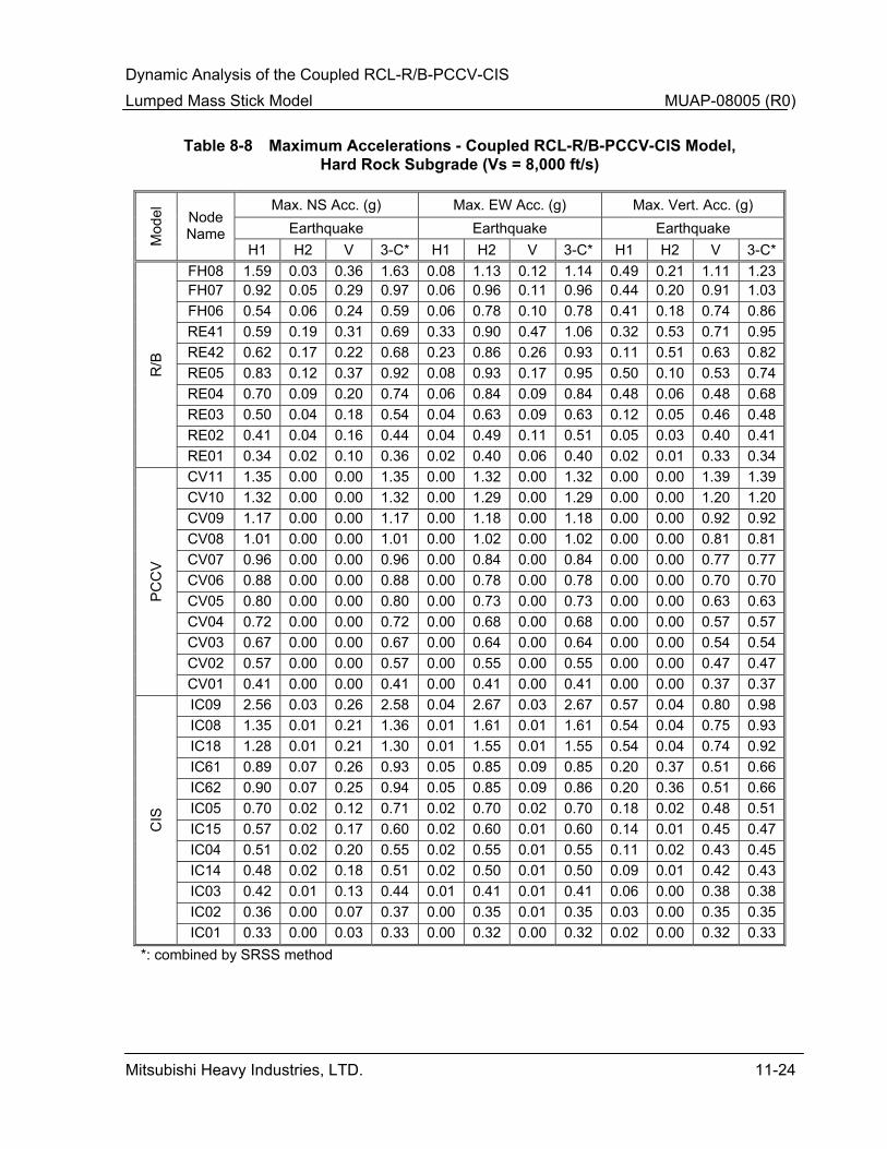
Dynamic Analysis of the Coupled RCL-R/B-PCCV-CIS Lumped Mass Stick Model MUAP-08005 (R0)
Mitsubishi Heavy Industries, LTD. 11-24
Table 8-8 Maximum Accelerations - Coupled RCL-R/B-PCCV-CIS Model, Hard Rock Subgrade (Vs = 8,000 ft/s)
Max. NS Acc. (g) Max. EW Acc. (g) Max. Vert. Acc. (g) Earthquake Earthquake Earthquake
Mod
el
Node Name
H1 H2 V 3-C* H1 H2 V 3-C* H1 H2 V 3-C*FH08 1.59 0.03 0.36 1.63 0.08 1.13 0.12 1.14 0.49 0.21 1.11 1.23FH07 0.92 0.05 0.29 0.97 0.06 0.96 0.11 0.96 0.44 0.20 0.91 1.03FH06 0.54 0.06 0.24 0.59 0.06 0.78 0.10 0.78 0.41 0.18 0.74 0.86RE41 0.59 0.19 0.31 0.69 0.33 0.90 0.47 1.06 0.32 0.53 0.71 0.95RE42 0.62 0.17 0.22 0.68 0.23 0.86 0.26 0.93 0.11 0.51 0.63 0.82RE05 0.83 0.12 0.37 0.92 0.08 0.93 0.17 0.95 0.50 0.10 0.53 0.74RE04 0.70 0.09 0.20 0.74 0.06 0.84 0.09 0.84 0.48 0.06 0.48 0.68RE03 0.50 0.04 0.18 0.54 0.04 0.63 0.09 0.63 0.12 0.05 0.46 0.48RE02 0.41 0.04 0.16 0.44 0.04 0.49 0.11 0.51 0.05 0.03 0.40 0.41
R/B
RE01 0.34 0.02 0.10 0.36 0.02 0.40 0.06 0.40 0.02 0.01 0.33 0.34CV11 1.35 0.00 0.00 1.35 0.00 1.32 0.00 1.32 0.00 0.00 1.39 1.39CV10 1.32 0.00 0.00 1.32 0.00 1.29 0.00 1.29 0.00 0.00 1.20 1.20CV09 1.17 0.00 0.00 1.17 0.00 1.18 0.00 1.18 0.00 0.00 0.92 0.92CV08 1.01 0.00 0.00 1.01 0.00 1.02 0.00 1.02 0.00 0.00 0.81 0.81CV07 0.96 0.00 0.00 0.96 0.00 0.84 0.00 0.84 0.00 0.00 0.77 0.77CV06 0.88 0.00 0.00 0.88 0.00 0.78 0.00 0.78 0.00 0.00 0.70 0.70CV05 0.80 0.00 0.00 0.80 0.00 0.73 0.00 0.73 0.00 0.00 0.63 0.63CV04 0.72 0.00 0.00 0.72 0.00 0.68 0.00 0.68 0.00 0.00 0.57 0.57CV03 0.67 0.00 0.00 0.67 0.00 0.64 0.00 0.64 0.00 0.00 0.54 0.54CV02 0.57 0.00 0.00 0.57 0.00 0.55 0.00 0.55 0.00 0.00 0.47 0.47
PC
CV
CV01 0.41 0.00 0.00 0.41 0.00 0.41 0.00 0.41 0.00 0.00 0.37 0.37IC09 2.56 0.03 0.26 2.58 0.04 2.67 0.03 2.67 0.57 0.04 0.80 0.98IC08 1.35 0.01 0.21 1.36 0.01 1.61 0.01 1.61 0.54 0.04 0.75 0.93IC18 1.28 0.01 0.21 1.30 0.01 1.55 0.01 1.55 0.54 0.04 0.74 0.92IC61 0.89 0.07 0.26 0.93 0.05 0.85 0.09 0.85 0.20 0.37 0.51 0.66IC62 0.90 0.07 0.25 0.94 0.05 0.85 0.09 0.86 0.20 0.36 0.51 0.66IC05 0.70 0.02 0.12 0.71 0.02 0.70 0.02 0.70 0.18 0.02 0.48 0.51IC15 0.57 0.02 0.17 0.60 0.02 0.60 0.01 0.60 0.14 0.01 0.45 0.47IC04 0.51 0.02 0.20 0.55 0.02 0.55 0.01 0.55 0.11 0.02 0.43 0.45IC14 0.48 0.02 0.18 0.51 0.02 0.50 0.01 0.50 0.09 0.01 0.42 0.43IC03 0.42 0.01 0.13 0.44 0.01 0.41 0.01 0.41 0.06 0.00 0.38 0.38IC02 0.36 0.00 0.07 0.37 0.00 0.35 0.01 0.35 0.03 0.00 0.35 0.35
CIS
IC01 0.33 0.00 0.03 0.33 0.00 0.32 0.00 0.32 0.02 0.00 0.32 0.33*: combined by SRSS method

Dynamic Analysis of the Coupled RCL-R/B-PCCV-CIS Lumped Mass Stick Model MUAP-08005 (R0)
Mitsubishi Heavy Industries, LTD. 11-25
Table 8-9 Model Forces and Moment - Coupled RCL-R/B-PCCV-CIS Model
NS Direction EW Direction M
odel
Node Name
EL. (in) Shear Force
(kip) Moment (kip-ft)
Shear Force (kip)
Moment (kip-ft)
FH08 1,854 13,400 441,000 7,530 386,000 FH07 1,508 18,900 938,000 11,500 762,000 FH06 1,212 21,600 1,490,000 14,400 1,150,000 RE41 1,212 11,100 385,000 7,820 246,000 RE42 1,212 6,230 317,000 4,010 125,000 RE05 1,386 13,700 346,000 14,900 705,000 RE04 1,212 24,200 951,000 31,500 1,780,000 RE03 917 78,200 8,350,000 93,300 6,630,000 RE02 602 112,000 11,700,000 127,000 10,300,000
R/B
RE01 303 138,000 14,500,000 153,000 13,700,000 CV11 2,762 1,650 8,850 1,740 9,360 CV10 2,700 9,380 247,000 9,910 262,000 CV09 2,420 22,400 983,000 23,500 1,040,000 CV08 2,077 34,800 2,090,000 36,300 2,200,000 CV07 1,747 49,500 3,800,000 51,100 3,960,000 CV06 1,386 58,100 5,300,000 60,300 5,500,000 CV05 1,106 63,800 6,410,000 67,700 6,630,000 CV04 917 67,000 7,010,000 71,600 7,250,000 CV03 819 69,800 8,300,000 75,100 8,580,000 CV02 602 73,400 10,200,000 79,400 10,500,000
PC
CV
CV01 303 76,100 11,900,000 82,200 12,400,000 IC09 1,674 1,800 50,100 1,880 53,300 IC08 1,348 4,670 62,500 4,900 68,900IC18 1,329 5,170 239,000 5,420 256,000 IC61 917 4,190 88,000 3,740 75,300 IC62 1,159 4,410 92,800 3,940 79,300 IC05 1,159 24,100 768,000 23,000 783,000 IC15 917 24,200 985,000 23,100 969,000 IC04 710 31,600 1,180,000 29,700 1,160,000 IC14 602 32,800 1,510,000 30,500 1,460,000 IC03 548 37,700 1,920,000 34,300 1,840,000 IC02 427.25 42,400 2,400,000 40,100 2,300,000
CIS
IC01 303 47,400 3,100,000 48,100 2,910,000
Notes: 1. The forces and moments shown above envelope all four generic Subgrade conditions
and are applied to the FE models for structural design as described in US-APWR DCD Section 3.8.
2. The forces and moments are obtained by combination of the three orthogonal directions used in the model by SRSS or the Newmark 100%-40%-40% method.

Dynamic Analysis of the Coupled RCL-R/B-PCCV-CIS Lumped Mass Stick Model MUAP-08005 (R0)
Mitsubishi Heavy Industries, LTD. 11-26
Table 8-10 Model Design Forces - R/B-PCCV-CIS Model
NS Direction EW Direction M
odel
Node Name
EL. (in) Shear Force
(kip) Moment (kip-ft)
Shear Force (kip)
Moment (kip-ft)
FH08 1,854 16,000 533,000 8,500 425,000 FH07 1,508 22,500 1,130,000 13,600 850,000 FH06 1,212 25,500 1,780,000 17,300 1,270,000 RE41 1,212 15,400 442,000 9,200 275,000 RE42 1,212 7,800 333,000 4,400 150,000 RE05 1,386 17,600 458,000 18,600 942,000 RE04 1,212 30,800 1,170,000 40,200 2,420,000 RE03 917 95,800 12,100,000 108,100 8,160,000 RE02 602 137,600 16,300,000 152,100 12,200,000
R/B
RE01 303 168,200 19,700,000 184,000 16,100,000 CV11 2,762 1,910 10,300 1,910 10,300 CV10 2,700 10,900 288,000 10,900 288,000 CV09 2,420 25,900 1,140,000 25,900 1,140,000 CV08 2,077 40,100 2,430,000 40,100 2,430,000 CV07 1,747 56,500 4,370,000 56,500 4,370,000 CV06 1,386 66,200 6,080,000 66,200 6,080,000 CV05 1,106 73,600 7,340,000 73,600 7,340,000 CV04 917 78,200 8,020,000 78,200 8,020,000 CV03 819 82,000 9,500,000 82,000 9,500,000 CV02 602 87,100 11,700,000 87,100 11,700,000
PC
CV
CV01 303 90,500 13,800,000 90,500 13,800,000 IC09 1,674 2,300 63,300 2,500 71,700IC08 1,348 5,800 83,300 6,500 100,000 IC18 1,329 6,300 300,000 7,200 342,000 IC61 917 5,300 117,000 5,100 100,000 IC62 1,159 5,300 117,000 5,300 108,000 IC05 1,159 33,800 1,040,000 30,400 1,040,000 IC15 917 34,200 1,350,000 30,800 1,330,000 IC04 710 45,900 1,650,000 40,600 1,590,000 IC14 602 47,900 2,150,000 42,300 2,030,000 IC03 548 54,300 2,770,000 48,000 2,560,000 IC02 427.25 61,300 3,390,000 54,700 3,130,000
CIS
IC01 303 68,000 4,380,000 61,300 4,030,000
Notes: 1. The forces and moments shown above envelope all four generic Subgrade conditions
and are applied to the FE models for structural design as described in US-APWR DCD Section 3.8.
2. The forces and moments are obtained by combination of the three orthogonal directions used in the model by SRSS or the Newmark 100%-40%-40% method.
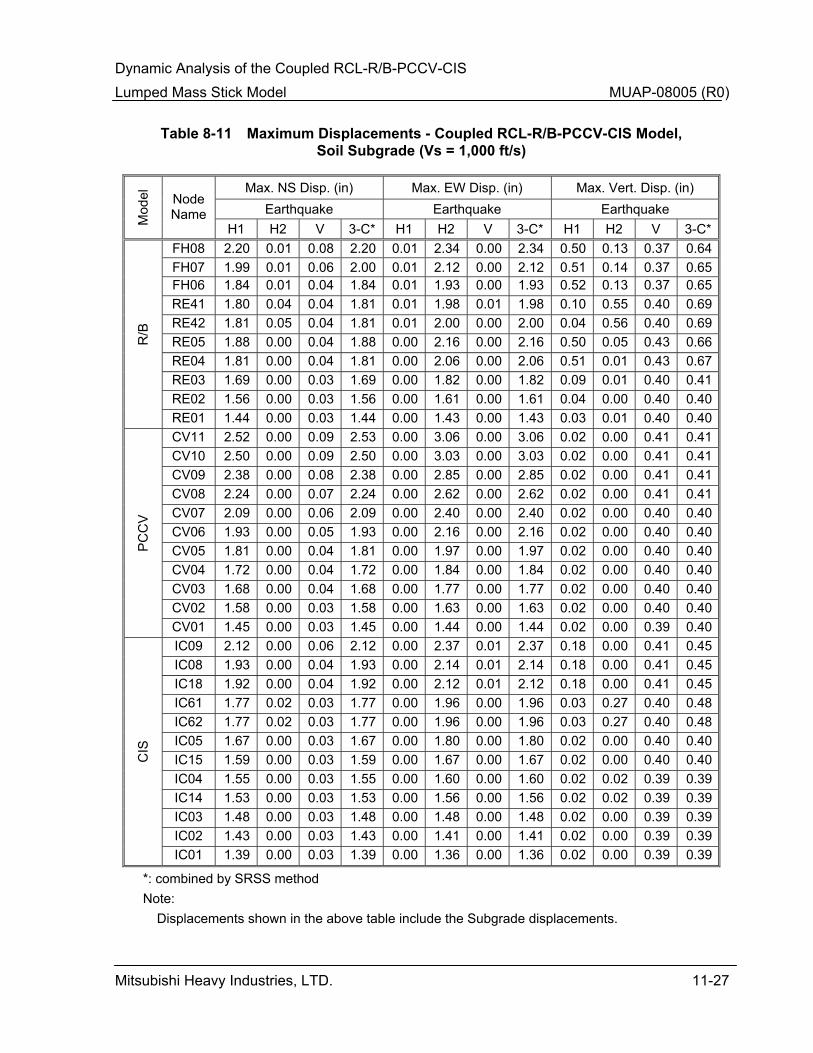
Dynamic Analysis of the Coupled RCL-R/B-PCCV-CIS Lumped Mass Stick Model MUAP-08005 (R0)
Mitsubishi Heavy Industries, LTD. 11-27
Table 8-11 Maximum Displacements - Coupled RCL-R/B-PCCV-CIS Model, Soil Subgrade (Vs = 1,000 ft/s)
Max. NS Disp. (in) Max. EW Disp. (in) Max. Vert. Disp. (in) Earthquake Earthquake Earthquake
Mod
el
Node Name
H1 H2 V 3-C* H1 H2 V 3-C* H1 H2 V 3-C*FH08 2.20 0.01 0.08 2.20 0.01 2.34 0.00 2.34 0.50 0.13 0.37 0.64 FH07 1.99 0.01 0.06 2.00 0.01 2.12 0.00 2.12 0.51 0.14 0.37 0.65 FH06 1.84 0.01 0.04 1.84 0.01 1.93 0.00 1.93 0.52 0.13 0.37 0.65 RE41 1.80 0.04 0.04 1.81 0.01 1.98 0.01 1.98 0.10 0.55 0.40 0.69 RE42 1.81 0.05 0.04 1.81 0.01 2.00 0.00 2.00 0.04 0.56 0.40 0.69 RE05 1.88 0.00 0.04 1.88 0.00 2.16 0.00 2.16 0.50 0.05 0.43 0.66 RE04 1.81 0.00 0.04 1.81 0.00 2.06 0.00 2.06 0.51 0.01 0.43 0.67 RE03 1.69 0.00 0.03 1.69 0.00 1.82 0.00 1.82 0.09 0.01 0.40 0.41 RE02 1.56 0.00 0.03 1.56 0.00 1.61 0.00 1.61 0.04 0.00 0.40 0.40
R/B
RE01 1.44 0.00 0.03 1.44 0.00 1.43 0.00 1.43 0.03 0.01 0.40 0.40 CV11 2.52 0.00 0.09 2.53 0.00 3.06 0.00 3.06 0.02 0.00 0.41 0.41 CV10 2.50 0.00 0.09 2.50 0.00 3.03 0.00 3.03 0.02 0.00 0.41 0.41 CV09 2.38 0.00 0.08 2.38 0.00 2.85 0.00 2.85 0.02 0.00 0.41 0.41 CV08 2.24 0.00 0.07 2.24 0.00 2.62 0.00 2.62 0.02 0.00 0.41 0.41 CV07 2.09 0.00 0.06 2.09 0.00 2.40 0.00 2.40 0.02 0.00 0.40 0.40 CV06 1.93 0.00 0.05 1.93 0.00 2.16 0.00 2.16 0.02 0.00 0.40 0.40 CV05 1.81 0.00 0.04 1.81 0.00 1.97 0.00 1.97 0.02 0.00 0.40 0.40 CV04 1.72 0.00 0.04 1.72 0.00 1.84 0.00 1.84 0.02 0.00 0.40 0.40 CV03 1.68 0.00 0.04 1.68 0.00 1.77 0.00 1.77 0.02 0.00 0.40 0.40 CV02 1.58 0.00 0.03 1.58 0.00 1.63 0.00 1.63 0.02 0.00 0.40 0.40
PC
CV
CV01 1.45 0.00 0.03 1.45 0.00 1.44 0.00 1.44 0.02 0.00 0.39 0.40 IC09 2.12 0.00 0.06 2.12 0.00 2.37 0.01 2.37 0.18 0.00 0.41 0.45 IC08 1.93 0.00 0.04 1.93 0.00 2.14 0.01 2.14 0.18 0.00 0.41 0.45 IC18 1.92 0.00 0.04 1.92 0.00 2.12 0.01 2.12 0.18 0.00 0.41 0.45 IC61 1.77 0.02 0.03 1.77 0.00 1.96 0.00 1.96 0.03 0.27 0.40 0.48 IC62 1.77 0.02 0.03 1.77 0.00 1.96 0.00 1.96 0.03 0.27 0.40 0.48 IC05 1.67 0.00 0.03 1.67 0.00 1.80 0.00 1.80 0.02 0.00 0.40 0.40 IC15 1.59 0.00 0.03 1.59 0.00 1.67 0.00 1.67 0.02 0.00 0.40 0.40 IC04 1.55 0.00 0.03 1.55 0.00 1.60 0.00 1.60 0.02 0.02 0.39 0.39 IC14 1.53 0.00 0.03 1.53 0.00 1.56 0.00 1.56 0.02 0.02 0.39 0.39 IC03 1.48 0.00 0.03 1.48 0.00 1.48 0.00 1.48 0.02 0.00 0.39 0.39 IC02 1.43 0.00 0.03 1.43 0.00 1.41 0.00 1.41 0.02 0.00 0.39 0.39
CIS
IC01 1.39 0.00 0.03 1.39 0.00 1.36 0.00 1.36 0.02 0.00 0.39 0.39
*: combined by SRSS method Note:
Displacements shown in the above table include the Subgrade displacements.
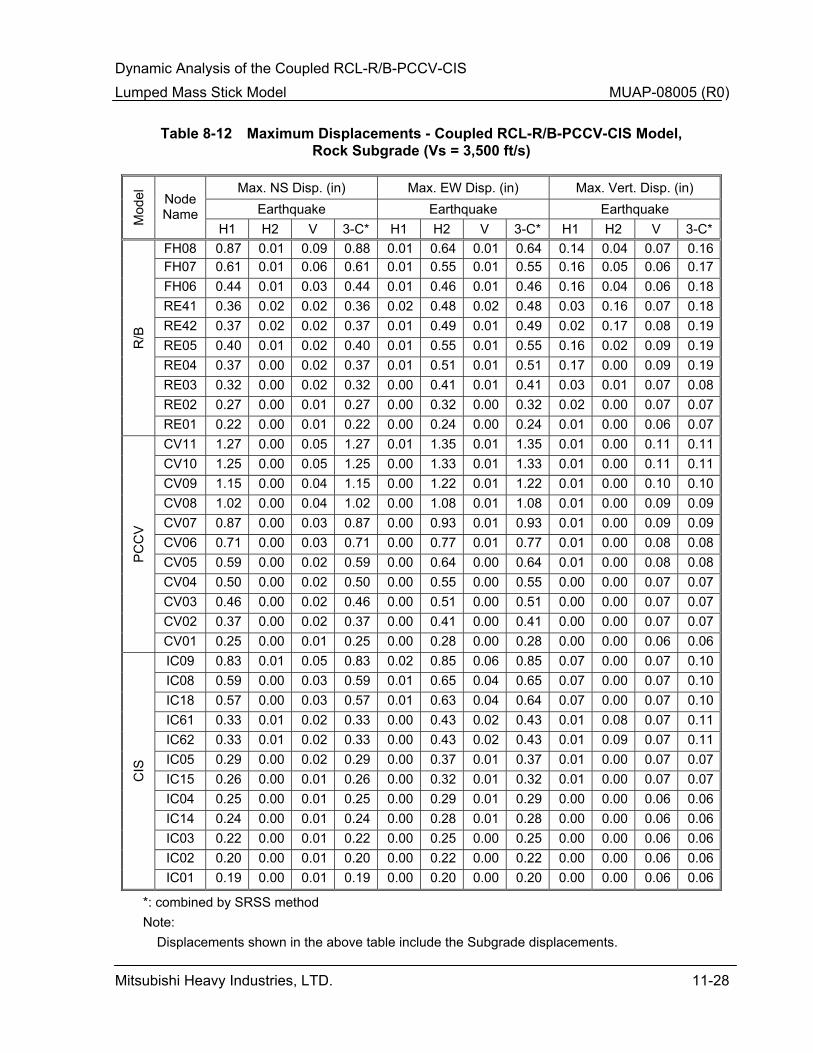
Dynamic Analysis of the Coupled RCL-R/B-PCCV-CIS Lumped Mass Stick Model MUAP-08005 (R0)
Mitsubishi Heavy Industries, LTD. 11-28
Table 8-12 Maximum Displacements - Coupled RCL-R/B-PCCV-CIS Model, Rock Subgrade (Vs = 3,500 ft/s)
Max. NS Disp. (in) Max. EW Disp. (in) Max. Vert. Disp. (in) Earthquake Earthquake Earthquake
Mod
el
Node Name
H1 H2 V 3-C* H1 H2 V 3-C* H1 H2 V 3-C*FH08 0.87 0.01 0.09 0.88 0.01 0.64 0.01 0.64 0.14 0.04 0.07 0.16 FH07 0.61 0.01 0.06 0.61 0.01 0.55 0.01 0.55 0.16 0.05 0.06 0.17 FH06 0.44 0.01 0.03 0.44 0.01 0.46 0.01 0.46 0.16 0.04 0.06 0.18 RE41 0.36 0.02 0.02 0.36 0.02 0.48 0.02 0.48 0.03 0.16 0.07 0.18 RE42 0.37 0.02 0.02 0.37 0.01 0.49 0.01 0.49 0.02 0.17 0.08 0.19 RE05 0.40 0.01 0.02 0.40 0.01 0.55 0.01 0.55 0.16 0.02 0.09 0.19 RE04 0.37 0.00 0.02 0.37 0.01 0.51 0.01 0.51 0.17 0.00 0.09 0.19 RE03 0.32 0.00 0.02 0.32 0.00 0.41 0.01 0.41 0.03 0.01 0.07 0.08 RE02 0.27 0.00 0.01 0.27 0.00 0.32 0.00 0.32 0.02 0.00 0.07 0.07
R/B
RE01 0.22 0.00 0.01 0.22 0.00 0.24 0.00 0.24 0.01 0.00 0.06 0.07 CV11 1.27 0.00 0.05 1.27 0.01 1.35 0.01 1.35 0.01 0.00 0.11 0.11 CV10 1.25 0.00 0.05 1.25 0.00 1.33 0.01 1.33 0.01 0.00 0.11 0.11 CV09 1.15 0.00 0.04 1.15 0.00 1.22 0.01 1.22 0.01 0.00 0.10 0.10 CV08 1.02 0.00 0.04 1.02 0.00 1.08 0.01 1.08 0.01 0.00 0.09 0.09 CV07 0.87 0.00 0.03 0.87 0.00 0.93 0.01 0.93 0.01 0.00 0.09 0.09 CV06 0.71 0.00 0.03 0.71 0.00 0.77 0.01 0.77 0.01 0.00 0.08 0.08 CV05 0.59 0.00 0.02 0.59 0.00 0.64 0.00 0.64 0.01 0.00 0.08 0.08 CV04 0.50 0.00 0.02 0.50 0.00 0.55 0.00 0.55 0.00 0.00 0.07 0.07 CV03 0.46 0.00 0.02 0.46 0.00 0.51 0.00 0.51 0.00 0.00 0.07 0.07 CV02 0.37 0.00 0.02 0.37 0.00 0.41 0.00 0.41 0.00 0.00 0.07 0.07
PC
CV
CV01 0.25 0.00 0.01 0.25 0.00 0.28 0.00 0.28 0.00 0.00 0.06 0.06 IC09 0.83 0.01 0.05 0.83 0.02 0.85 0.06 0.85 0.07 0.00 0.07 0.10 IC08 0.59 0.00 0.03 0.59 0.01 0.65 0.04 0.65 0.07 0.00 0.07 0.10 IC18 0.57 0.00 0.03 0.57 0.01 0.63 0.04 0.64 0.07 0.00 0.07 0.10 IC61 0.33 0.01 0.02 0.33 0.00 0.43 0.02 0.43 0.01 0.08 0.07 0.11 IC62 0.33 0.01 0.02 0.33 0.00 0.43 0.02 0.43 0.01 0.09 0.07 0.11 IC05 0.29 0.00 0.02 0.29 0.00 0.37 0.01 0.37 0.01 0.00 0.07 0.07 IC15 0.26 0.00 0.01 0.26 0.00 0.32 0.01 0.32 0.01 0.00 0.07 0.07 IC04 0.25 0.00 0.01 0.25 0.00 0.29 0.01 0.29 0.00 0.00 0.06 0.06 IC14 0.24 0.00 0.01 0.24 0.00 0.28 0.01 0.28 0.00 0.00 0.06 0.06 IC03 0.22 0.00 0.01 0.22 0.00 0.25 0.00 0.25 0.00 0.00 0.06 0.06 IC02 0.20 0.00 0.01 0.20 0.00 0.22 0.00 0.22 0.00 0.00 0.06 0.06
CIS
IC01 0.19 0.00 0.01 0.19 0.00 0.20 0.00 0.20 0.00 0.00 0.06 0.06
*: combined by SRSS method Note:
Displacements shown in the above table include the Subgrade displacements.

Dynamic Analysis of the Coupled RCL-R/B-PCCV-CIS Lumped Mass Stick Model MUAP-08005 (R0)
Mitsubishi Heavy Industries, LTD. 11-29
Table 8-13 Maximum Displacements - Coupled RCL-R/B-PCCV-CIS Model, Rock Subgrade (Vs = 6,500 ft/s)
Max. NS Disp. (in) Max. EW Disp. (in) Max. Vert. Disp. (in) Earthquake Earthquake Earthquake
Mod
el
Node Name
H1 H2 V 3-C* H1 H2 V 3-C* H1 H2 V 3-C*FH08 0.86 0.01 0.10 0.86 0.01 0.40 0.02 0.40 0.12 0.03 0.05 0.13 FH07 0.50 0.01 0.05 0.51 0.01 0.33 0.01 0.33 0.12 0.03 0.04 0.14 FH06 0.27 0.01 0.03 0.27 0.01 0.27 0.01 0.27 0.12 0.03 0.04 0.13 RE41 0.20 0.02 0.03 0.21 0.03 0.30 0.03 0.30 0.02 0.11 0.05 0.13 RE42 0.21 0.02 0.02 0.21 0.02 0.30 0.01 0.30 0.02 0.12 0.05 0.13 RE05 0.23 0.01 0.03 0.23 0.01 0.34 0.01 0.34 0.14 0.02 0.06 0.15 RE04 0.21 0.01 0.02 0.21 0.01 0.31 0.01 0.31 0.14 0.01 0.06 0.15 RE03 0.17 0.00 0.02 0.18 0.00 0.24 0.01 0.24 0.03 0.01 0.04 0.05 RE02 0.13 0.00 0.02 0.14 0.00 0.18 0.01 0.18 0.01 0.00 0.03 0.03
R/B
RE01 0.09 0.00 0.01 0.09 0.00 0.12 0.00 0.12 0.01 0.00 0.03 0.03 CV11 1.06 0.01 0.04 1.06 0.00 1.14 0.01 1.14 0.01 0.00 0.11 0.11 CV10 1.04 0.01 0.04 1.04 0.00 1.12 0.01 1.12 0.01 0.00 0.10 0.10 CV09 0.95 0.00 0.03 0.95 0.00 1.03 0.01 1.03 0.01 0.00 0.08 0.08 CV08 0.83 0.00 0.03 0.83 0.00 0.90 0.01 0.90 0.01 0.00 0.07 0.07 CV07 0.70 0.00 0.02 0.70 0.00 0.76 0.01 0.77 0.01 0.00 0.07 0.07 CV06 0.55 0.00 0.02 0.55 0.00 0.61 0.01 0.61 0.01 0.00 0.06 0.06 CV05 0.44 0.00 0.02 0.44 0.00 0.49 0.01 0.49 0.00 0.00 0.05 0.05 CV04 0.36 0.00 0.01 0.36 0.00 0.41 0.00 0.41 0.00 0.00 0.05 0.05 CV03 0.32 0.00 0.01 0.32 0.00 0.36 0.00 0.36 0.00 0.00 0.05 0.05 CV02 0.24 0.00 0.01 0.24 0.00 0.27 0.00 0.27 0.00 0.00 0.04 0.04
PC
CV
CV01 0.13 0.00 0.01 0.14 0.00 0.16 0.00 0.16 0.00 0.00 0.03 0.03 IC09 0.84 0.01 0.07 0.84 0.01 0.64 0.03 0.64 0.06 0.00 0.04 0.07 IC08 0.51 0.00 0.04 0.51 0.01 0.44 0.02 0.44 0.06 0.00 0.04 0.07 IC18 0.49 0.00 0.04 0.49 0.01 0.43 0.02 0.43 0.06 0.00 0.04 0.07 IC61 0.23 0.02 0.03 0.23 0.00 0.28 0.01 0.28 0.01 0.07 0.03 0.07 IC62 0.23 0.02 0.03 0.23 0.00 0.28 0.01 0.28 0.01 0.07 0.03 0.07 IC05 0.19 0.00 0.02 0.19 0.00 0.22 0.01 0.22 0.01 0.00 0.03 0.03 IC15 0.15 0.00 0.01 0.15 0.00 0.17 0.00 0.17 0.00 0.00 0.03 0.03 IC04 0.13 0.00 0.01 0.13 0.00 0.15 0.00 0.15 0.00 0.00 0.02 0.03 IC14 0.12 0.00 0.01 0.12 0.00 0.14 0.00 0.14 0.00 0.00 0.02 0.02 IC03 0.10 0.00 0.01 0.10 0.00 0.11 0.00 0.11 0.00 0.00 0.02 0.02 IC02 0.08 0.00 0.01 0.08 0.00 0.09 0.00 0.09 0.00 0.00 0.02 0.02
CIS
IC01 0.07 0.00 0.01 0.07 0.00 0.08 0.00 0.08 0.00 0.00 0.02 0.02
*: combined by SRSS method Note:
Displacements shown in the above table include the Subgrade displacements.

Dynamic Analysis of the Coupled RCL-R/B-PCCV-CIS Lumped Mass Stick Model MUAP-08005 (R0)
Mitsubishi Heavy Industries, LTD. 11-30
Table 8-14 Maximum Displacements - Coupled RCL-R/B-PCCV-CIS Model, Hard Rock Subgrade (Vs = 8,000 ft/s)
Max. NS Disp. (in) Max. EW Disp. (in) Max. Vert. Disp. (in) Earthquake Earthquake Earthquake
Mod
el
Node Name
H1 H2 V 3-C* H1 H2 V 3-C* H1 H2 V 3-C*FH08 0.59 0.01 0.08 0.59 0.01 0.29 0.02 0.29 0.07 0.03 0.04 0.08 FH07 0.33 0.01 0.04 0.33 0.01 0.23 0.01 0.23 0.07 0.03 0.03 0.08 FH06 0.16 0.01 0.02 0.17 0.01 0.17 0.01 0.17 0.07 0.02 0.03 0.08 RE41 0.11 0.02 0.03 0.12 0.03 0.19 0.03 0.20 0.02 0.08 0.03 0.09 RE42 0.12 0.02 0.02 0.12 0.02 0.19 0.01 0.19 0.01 0.08 0.03 0.09 RE05 0.14 0.01 0.03 0.15 0.01 0.23 0.01 0.23 0.07 0.01 0.04 0.08 RE04 0.13 0.01 0.02 0.13 0.01 0.20 0.01 0.20 0.08 0.01 0.03 0.08 RE03 0.09 0.00 0.02 0.09 0.00 0.13 0.01 0.14 0.02 0.01 0.02 0.02 RE02 0.06 0.00 0.01 0.06 0.00 0.08 0.01 0.08 0.01 0.00 0.01 0.01
R/B
RE01 0.03 0.00 0.01 0.03 0.00 0.03 0.00 0.03 0.00 0.00 0.01 0.01 CV11 0.61 0.00 0.00 0.61 0.00 0.61 0.00 0.61 0.00 0.00 0.09 0.09 CV10 0.60 0.00 0.00 0.60 0.00 0.60 0.00 0.60 0.00 0.00 0.08 0.08 CV09 0.55 0.00 0.00 0.55 0.00 0.55 0.00 0.55 0.00 0.00 0.06 0.06 CV08 0.48 0.00 0.00 0.48 0.00 0.47 0.00 0.47 0.00 0.00 0.05 0.05 CV07 0.40 0.00 0.00 0.40 0.00 0.39 0.00 0.39 0.00 0.00 0.05 0.05 CV06 0.32 0.00 0.00 0.32 0.00 0.30 0.00 0.30 0.00 0.00 0.04 0.04 CV05 0.25 0.00 0.00 0.25 0.00 0.23 0.00 0.23 0.00 0.00 0.03 0.03 CV04 0.20 0.00 0.00 0.20 0.00 0.19 0.00 0.19 0.00 0.00 0.03 0.03 CV03 0.18 0.00 0.00 0.18 0.00 0.16 0.00 0.16 0.00 0.00 0.03 0.03 CV02 0.12 0.00 0.00 0.12 0.00 0.11 0.00 0.11 0.00 0.00 0.02 0.02
PC
CV
CV01 0.06 0.00 0.00 0.06 0.00 0.05 0.00 0.05 0.00 0.00 0.01 0.01 IC09 0.70 0.00 0.05 0.70 0.00 0.63 0.00 0.63 0.05 0.00 0.02 0.05 IC08 0.40 0.00 0.03 0.40 0.00 0.42 0.00 0.42 0.05 0.00 0.02 0.05 IC18 0.38 0.00 0.02 0.38 0.00 0.40 0.00 0.40 0.05 0.00 0.02 0.05 IC61 0.12 0.01 0.01 0.12 0.00 0.17 0.00 0.17 0.01 0.05 0.01 0.05 IC62 0.12 0.01 0.01 0.12 0.00 0.17 0.00 0.17 0.01 0.05 0.01 0.05 IC05 0.09 0.00 0.01 0.09 0.00 0.12 0.00 0.12 0.01 0.00 0.01 0.01 IC15 0.06 0.00 0.01 0.06 0.00 0.08 0.00 0.08 0.00 0.00 0.01 0.01 IC04 0.05 0.00 0.00 0.05 0.00 0.06 0.00 0.06 0.00 0.00 0.01 0.01 IC14 0.04 0.00 0.00 0.04 0.00 0.05 0.00 0.05 0.00 0.00 0.00 0.01 IC03 0.02 0.00 0.00 0.03 0.00 0.03 0.00 0.03 0.00 0.00 0.00 0.00 IC02 0.01 0.00 0.00 0.01 0.00 0.01 0.00 0.01 0.00 0.00 0.00 0.00
CIS
IC01 0.01 0.00 0.00 0.01 0.00 0.01 0.00 0.01 0.00 0.00 0.00 0.00
*: combined by SRSS method Note:
Displacements shown in the above table are from the top of basemat.

Dynamic Analysis of the Coupled RCL-R/B-PCCV-CIS Lumped Mass Stick Model MUAP-08005 (R0)
Mitsubishi Heavy Industries, LTD. 12-1
Figure 2-2 US-APWR Cross Section of R/B
Figure 2-1 US-APWR Plan of R/B Complex at Operating Floor Level Figure 2-1 US-APWR Plan of R/B Complex at Operating Floor Level
Security-Related Information - Withhold Under 10 CFR 2.390
Security-Related Information - Withhold Under 10 CFR 2.390
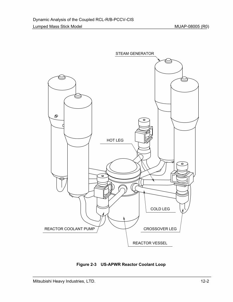
Dynamic Analysis of the Coupled RCL-R/B-PCCV-CIS Lumped Mass Stick Model MUAP-08005 (R0)
Mitsubishi Heavy Industries, LTD. 12-2
Figure 2-3 US-APWR Reactor Coolant Loop
STEAM GENERATOR
REACTOR COOLANT PUMP
REACTOR VESSEL
CROSSOVER LEG
COLD LEG
HOT LEG
Dynamic Analysis of the Coupled RCL-R/B-PCCV-CIS Lumped Mass Stick Model MUAP-08005 (R0)
Mitsubishi Heavy Industries, LTD. 12-3
Figure 3-1 Lumped Mass Stick Model for Buildings (R/B,PCCV,CIS)
Security-Related Information - Withhold Under 10 CFR 2.390

Dynamic Analysis of the Coupled RCL-R/B-PCCV-CIS Lumped Mass Stick Model MUAP-08005 (R0)
Mitsubishi Heavy Industries, LTD. 12-4
0.0
0.5
1.0
1.5
2.0
0.1 1.0 10.0 100.0Frequency ( Hz )
Accele
ration (
G)
Note: spectra for damping 0.5, 2, 5, 7, 10%.
5%
0.5%
7%
10%
2%
Figure 5-1 US-APWR Horizontal CSDRS
(g)

Dynamic Analysis of the Coupled RCL-R/B-PCCV-CIS Lumped Mass Stick Model MUAP-08005 (R0)
Mitsubishi Heavy Industries, LTD. 12-5
0.0
0.5
1.0
1.5
2.0
0.1 1.0 10.0 100.0Frequency ( Hz )
Accele
ration (
G)
Note: spectra for damping 0.5, 2, 5, 7, 10%.
0.5%
2%
5%
7%
10%
Figure 5-2 US-APWR Vertical CSDRS
(g)

Dynamic Analysis of the Coupled RCL-R/B-PCCV-CIS Lumped Mass Stick Model MUAP-08005 (R0)
Mitsubishi Heavy Industries, LTD. 12-6
Figure 5-3 Artificial Time Histories Plots (H1)
H1 Accelerations
-0.4
0.0
0.4
0 5 10 15 20
Acc.(g
)
H1 Velocities
-20
0
20
0 5 10 15 20
Vel.(
in/se
c)
H1 Displacements
-10
0
10
0 5 10 15 20
Dis
p.(in)
Time(sec)
(g)
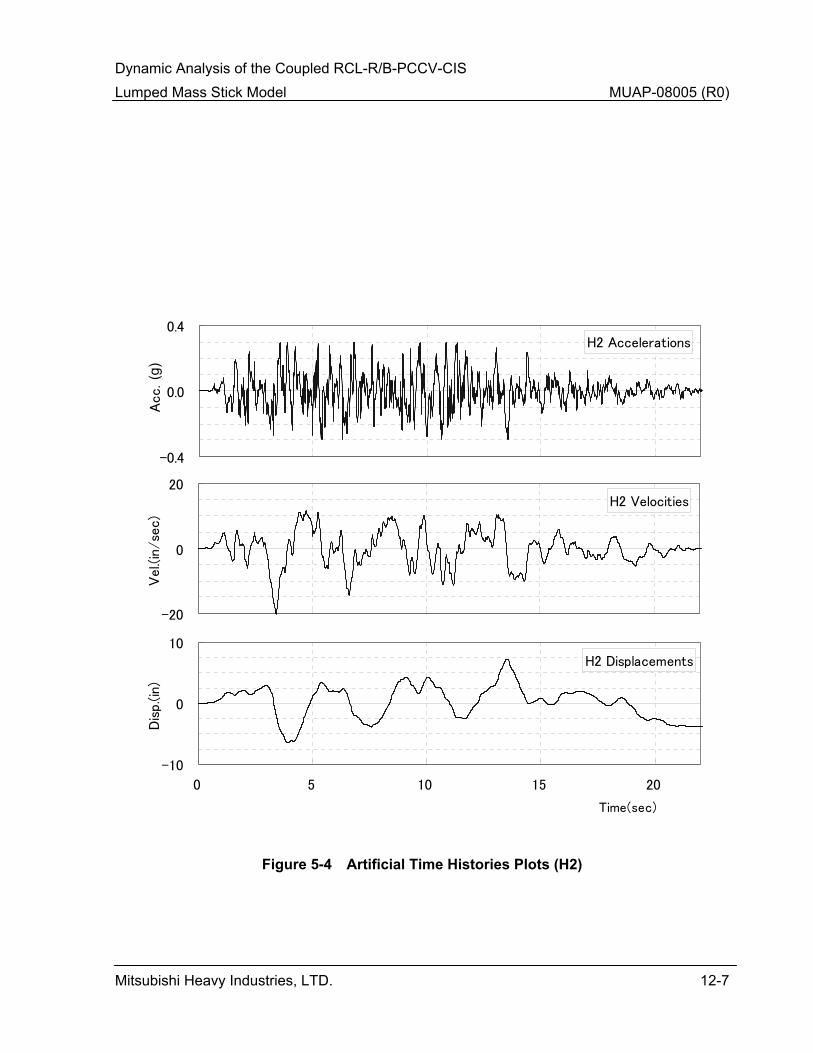
Dynamic Analysis of the Coupled RCL-R/B-PCCV-CIS Lumped Mass Stick Model MUAP-08005 (R0)
Mitsubishi Heavy Industries, LTD. 12-7
Figure 5-4 Artificial Time Histories Plots (H2)
H2 Accelerations
-0.4
0.0
0.4
0 5 10 15 20
Acc
.(g)
H2 Velocities
-20
0
20
0 5 10 15 20
Vel
.(in
/se
c)
H2 Displacements
-10
0
10
0 5 10 15 20
Dis
p.(i
n)
Time(sec)
(g)

Dynamic Analysis of the Coupled RCL-R/B-PCCV-CIS Lumped Mass Stick Model MUAP-08005 (R0)
Mitsubishi Heavy Industries, LTD. 12-8
Figure 5-5 Artificial Time Histories Plots (V)
V Accelerations
-0.4
0.0
0.4
0 5 10 15 20
Acc.(g
)
V Velocities
-20
0
20
0 5 10 15 20
Vel.(
in/se
c)
V Displacements
-10
0
10
0 5 10 15 20
Dis
p.(in)
Time(sec)
(g)
Dynamic Analysis of the Coupled RCL-R/B-PCCV-CIS Lumped Mass Stick Model MUAP-08005 (R0)
Mitsubishi Heavy Industries, LTD. 12-9
Figure 6-1 Lumped Mass Stick Model for Buildings (R/B, PCCV, CIS) (Sheet 1 of 3)
Security-Related Information - Withhold Under 10 CFR 2.390
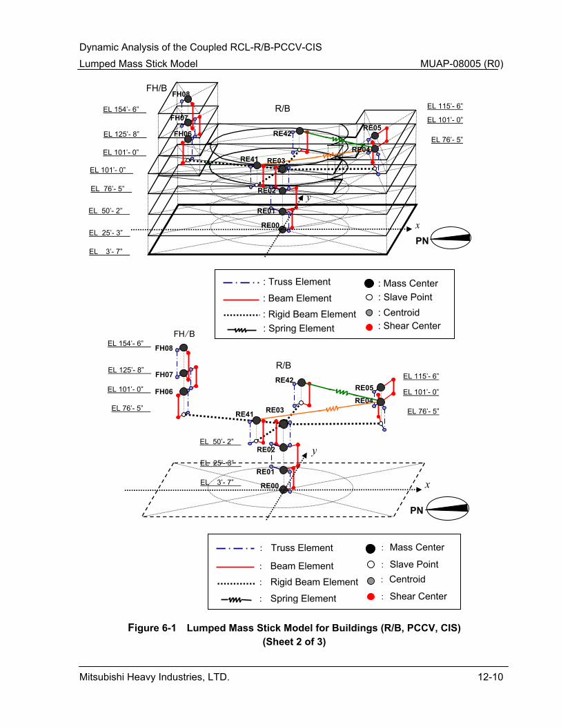
Dynamic Analysis of the Coupled RCL-R/B-PCCV-CIS Lumped Mass Stick Model MUAP-08005 (R0)
Mitsubishi Heavy Industries, LTD. 12-10
Figure 6-1 Lumped Mass Stick Model for Buildings (R/B, PCCV, CIS)
(Sheet 2 of 3)
FH/B : Spring Element
: Centroid
: Mass Center
: Shear Center
: Slave Point : Truss Element
: Beam Element : Rigid Beam Element
EL 3’- 7”
EL 25’- 3”
FH/B
R/B
RE00
FH07
FH06
EL 101’- 0”
EL 76’- 5”
EL 50’- 2”
RE42
RE41
EL 154’- 6”
EL 125’- 8”
EL 101’- 0”
EL 76’- 5”
EL 115’- 6”
EL 101’- 0”
FH08
RE05
PN x
yRE02
RE01
RE04RE03
RE04
RE41
EL 25’- 3”
EL 3’- 7”
R/B
RE00
RE02
FH07
FH06
EL 76’- 5”
EL 50’- 2”
RE42
EL 154’- 6”
EL 125’- 8”
EL 101’- 0”
EL 76’- 5”
EL 115’- 6”
EL 101’- 0”
FH08
RE05
RE03
: Centroid
: Mass Center
: Shear Center
: Slave Point
: Truss Element
: Beam Element: Rigid Beam Element
: Spring Element
x
y
PN
RE01
Dynamic Analysis of the Coupled RCL-R/B-PCCV-CIS Lumped Mass Stick Model MUAP-08005 (R0)
Mitsubishi Heavy Industries, LTD. 12-11
Note: Upper portion of this sheet shows the zoning above the operating floor at elevation 76 feet, 5
inches and the lower portion shows conceptual stick model with respect to configuration of the CIS.
Figure 6-1 Lumped Mass Stick Model for Buildings (R/B, PCCV, CIS) (Sheet 3 of 3)
Security-Related Information - Withhold Under 10 CFR 2.390

Dynamic Analysis of the Coupled RCL-R/B-PCCV-CIS Lumped Mass Stick Model MUAP-08005 (R0)
Mitsubishi Heavy Industries, LTD. 12-12
705
704703
702
706
707
708
709
710
2102 2105
2603
2604
2107 21093004 2111
21122113 2115
2117
2130
21412142
2143
2145
21472149
21512152
2153215521573007215921602161
2163
216521672168
23002173
2181
3014
3012
21832185
2186
2189
2191
21942196
26012602
2198
2129
2131
2132
21342121
2135
2133
2137
2139
2140
2120
2125
2201
2202
2203
2126
2204
2205
2206
2127
2207
2208
2209
2128
2210
2211
2212
2760
2761
2762
2763
2764
2765
2169
217521762360
23612177
2364
23652366
2180
2174 2170
2301
2302
2303
2171
2304
2305
2306
2172
2307
2308
2309
2811
41024105 4603
4604
4107
4109
50045005
4111
4112
41134115
4117 4130
41414142
4143
41454147414941514152
4153
41554157
5007
4159
41604161
4163
416541674168
4300
417341815013
5014
4183
4185418641894191
41944196 4601
4602
4198
4129
4131
4132
41344121
4135
4133
4137
4139
4140
4120
4125
4201
4202
4203
4126
4204
4205
4206
4207
4208
4209
4210
4211
4212
47624763
4764
4765
4169
417541764360
43614177
4364
43654366
4180
4174
4170
4301
4302
4303
4171
4304
4305
4306
4172
4307
4308
4309
4811
61026105
6603
6604
610761097004
6111
61126113
61156117
6130
61416142
6143
6145614761496151
61526153
61556157
70076159
61606161
6163
616561676168
6300
6173
6181 7013 6183
61856186
6189
61916194 6196
6601
6602
6198
6129
6131
6132
61346121
6135
6133
6137
6139
6140
6120
6125
6201
6202
6203
6204
62056206
6207
6208
6209
6128
6210
6211
6212
6760
6761
6762
6763
6764
6765
6169
617561766360
63616177
6364
63656366
6180
61746170
6301
6302
6303
6171
6304
6305
6306
6172
6307
6308
6309
6811
81028105
8603
8604
8107
8109
9004
81118112
8113
81158117
8130
8141
81428143814581478149
81518152
8153
8155
81579007
8159
8160
8161
8163
816581678168
8300
8173
8181
9014
8183
818581868189
81918194
8196
8601
8602
8198
8129
8131
8132
81348121
8135
8133
8137
8139
8140
81208125
8201
82028203
8204
8205
8206
8207
8208
8209
8210
8211
8212
8762
8763
8764
8765
8169
817581768360
83618177
8364
83658366
8180
8174
8170
8301
8302
8303
8171
8304
8305
8306
8172
8307
83088309
8811
712711
Global Coordinate SystemsYX
Z
PN
Mass Point
Fixed edge
Support
CROSS OVER LEG
COLD LEG
HOT LEG
Reactor Vessel
Reactor Coolant Pump
Steam Generator
LOOP-B
LOOP-A
LOOP-C
LOOP-D
Node Point
4127
4128
4768
4769
8126
8127
8128
8768
8769
8767
8766
6126
6127
6766
6767
3005
3013
5012
7005
7012
7014
9005
9012
9013
Figure 6-2 Stick Mass Spring Model for Reactor Coolant Loop
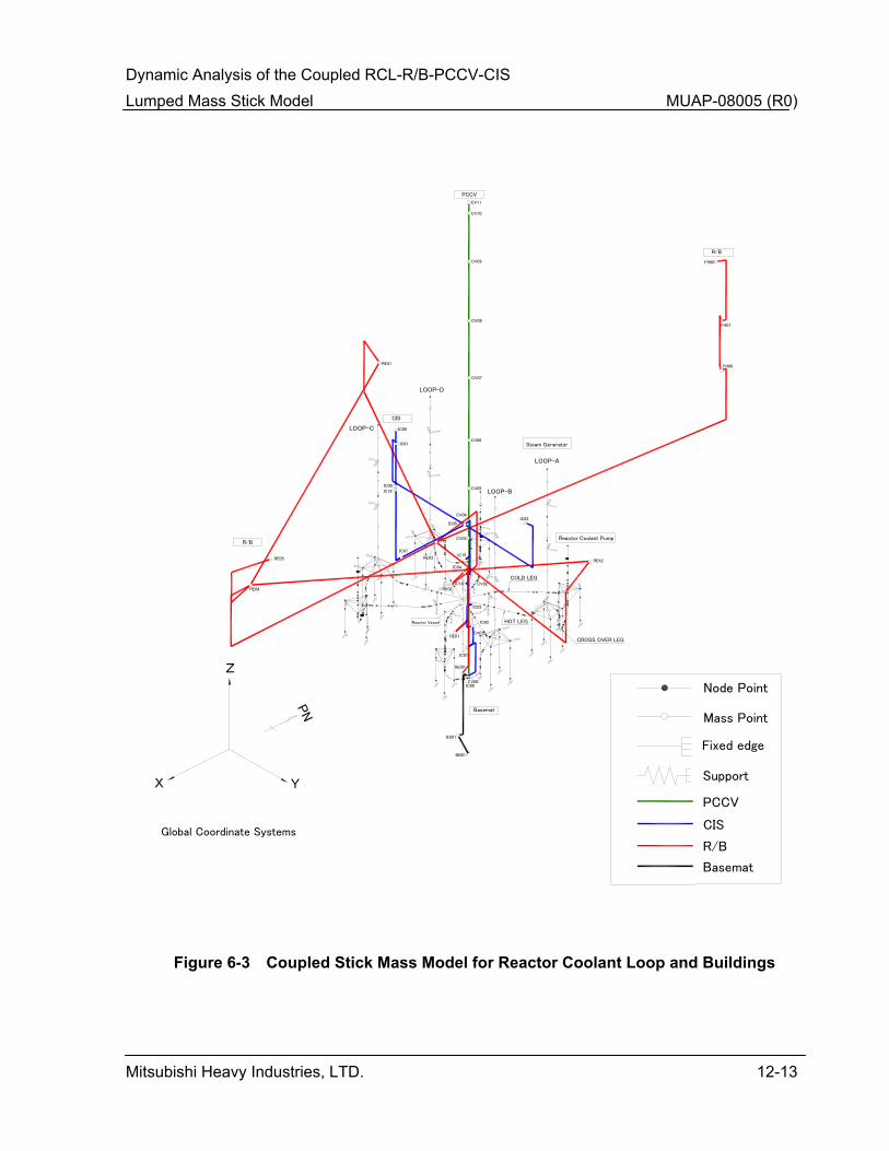
Dynamic Analysis of the Coupled RCL-R/B-PCCV-CIS Lumped Mass Stick Model MUAP-08005 (R0)
Mitsubishi Heavy Industries, LTD. 12-13
Figure 6-3 Coupled Stick Mass Model for Reactor Coolant Loop and Buildings
Global Coordinate Systems
YX
Z
PN
Mass Point
Fixed edge
Support
CROSS OVER LEG
COLD LEG
HOT LEGReactor Vessel
Reactor Coolant Pump
Steam Generator
LOOP-B
LOOP-A
LOOP-C
LOOP-D
Node PointIC00
IC01
IC02
IC03
IC14
IC04
IC15
IC05IC62
IC61
IC09
IC08IC18
IC07
PCCV
CIS
R/B
R/B
PCCV
FH08
FH07
FH06
RE42
CV11
CV10
CV09
CV08
CV07
CV06
CV05
CV04
CV03
CV02
CV01
CV00
RE41
RE05
RE04
RE03
RE02
BB01
BS01
RE00
RE01
CIS
R/B
Basemat
Basemat
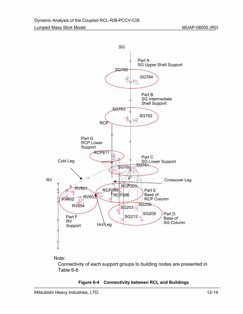
Dynamic Analysis of the Coupled RCL-R/B-PCCV-CIS Lumped Mass Stick Model MUAP-08005 (R0)
Mitsubishi Heavy Industries, LTD. 12-14
SG765 SG764
SG763 SG762
SG
RCP
RV
SG209
SG206
SG212
SG203
RCP309 RCP303
RCP306
SG761 SG760
RCP811
Cold Leg
Crossover Leg
RV601
RV602 RV604
RV603
Hot Leg
Part ASG Upper Shell Support
Part BSG Intermediate Shell Support
Part CSG Lower Support
Part D Base of SG Column
Part EBase of RCP Column
Part G RCP Lower Support
Part F RV Support
Note: Connectivity of each support groups to building nodes are presented in Table 6-8.
Figure 6-4 Connectivity between RCL and Buildings

Dynamic Analysis of the Coupled RCL-R/B-PCCV-CIS Lumped Mass Stick Model MUAP-08005 (R0)
Mitsubishi Heavy Industries, LTD. 12-15
Figure 6-5 Stick mass model for RV with internals
705
702
706
707
708
703704
710
709
Figure 6-5 Stick Mass Model for RV with Internals
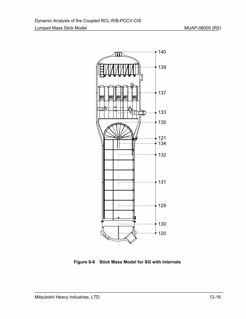
Dynamic Analysis of the Coupled RCL-R/B-PCCV-CIS Lumped Mass Stick Model MUAP-08005 (R0)
Mitsubishi Heavy Industries, LTD. 12-16
Figure 6-6 Stick Mass Model for SG with Internals
131
140
139
137
133
135
121134
129
132
130
120
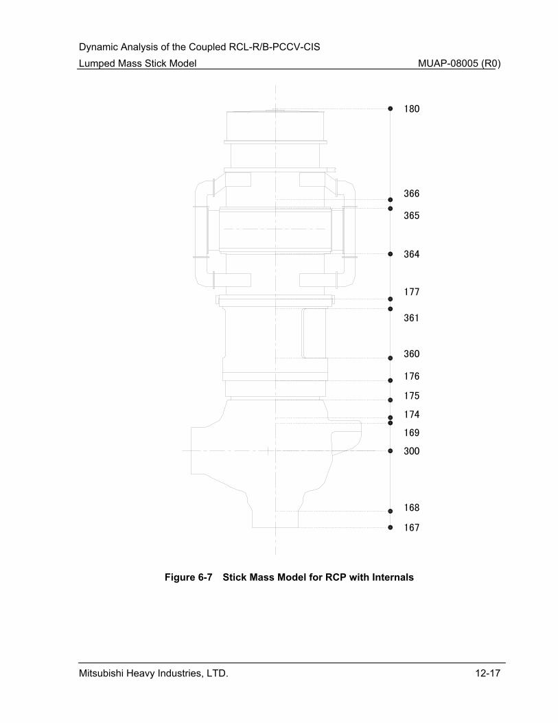
Dynamic Analysis of the Coupled RCL-R/B-PCCV-CIS Lumped Mass Stick Model MUAP-08005 (R0)
Mitsubishi Heavy Industries, LTD. 12-17
167
168
300
169
174
175
176
360
361
177
364
365
366
180
Figure 6-7 Stick mass model for RCP with internals Figure 6-7 Stick Mass Model for RCP with Internals

Dynamic Analysis of the Coupled RCL-R/B-PCCV-CIS Lumped Mass Stick Model MUAP-08005 (R0)
Mitsubishi Heavy Industries, LTD. 12-18
Figure 6-8 Reactor Coolant Loop Piping Model
107 109 111112
113
153
155157
159160161
181
183
185186
189191
(194)
(117)
115
141142
143
145,147,149,151,152
165,(167)
163
RCP
SG
Main Coolant PipingGlobal Layout
Hot Leg
Cold LegCross Over Leg
RVRCP
Cold Leg (Side View)
181 183 186
191
185(194)189
SGRV Hot Leg
115
111109107
(117)
112
(Side View)
113
RCP
SG
Cross Over Leg
141
152
155161
165
145
142
(167)
159 157160
147
151
(Side View)
143
163153
149
1014
1007
1004
1014
1004
1007
RV
1013
1012
10121013
1005
1005
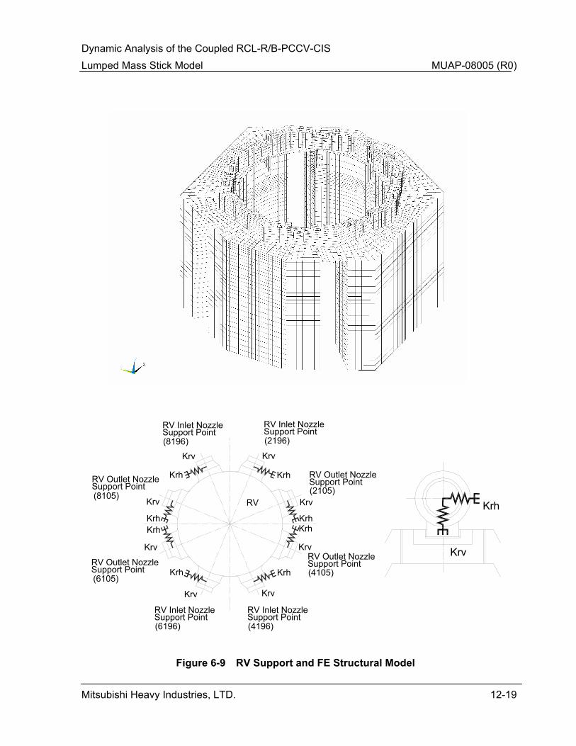
Dynamic Analysis of the Coupled RCL-R/B-PCCV-CIS Lumped Mass Stick Model MUAP-08005 (R0)
Mitsubishi Heavy Industries, LTD. 12-19
Figure 6-9 RV Support and FE Structural Model
Krh
Krv
RV
(2196)
Krv
Krh
(4196)
(8196)
(6196)
Krh Krh
Krh
Krh
Krh
Krh
Krh
(6105)
Support Point(2105)
(4105)
(8105)
Krv Krv
Krv
Krv
Krv Krv
Krv
Support Point Support Point
Support PointRV Outlet Nozzle
RV Outlet Nozzle RV Outlet Nozzle
RV Outlet Nozzle
Support PointRV Inlet Nozzle
Support PointRV Inlet Nozzle
Support PointRV Inlet Nozzle
Support PointRV Inlet Nozzle
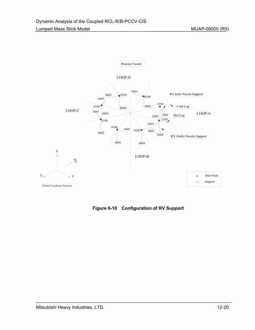
Dynamic Analysis of the Coupled RCL-R/B-PCCV-CIS Lumped Mass Stick Model MUAP-08005 (R0)
Mitsubishi Heavy Industries, LTD. 12-20
Figure 6-10 Configuration of RV Support
21052603
2604
2196
26012602
4105 4603
4604
4196 4601
4602
6105
6603
6604
6196
6601
6602
81058603
8604
8196
8601
8602
Global Coordinate Systems
YX
Z
PN
Cold Leg
Hot Leg
Reactor Vessel
LOOP-A
RV Inlet Nozzle Support
RV Outlet Nozzle Support
LOOP-B
LOOP-C
LOOP-D
Start Point
Support
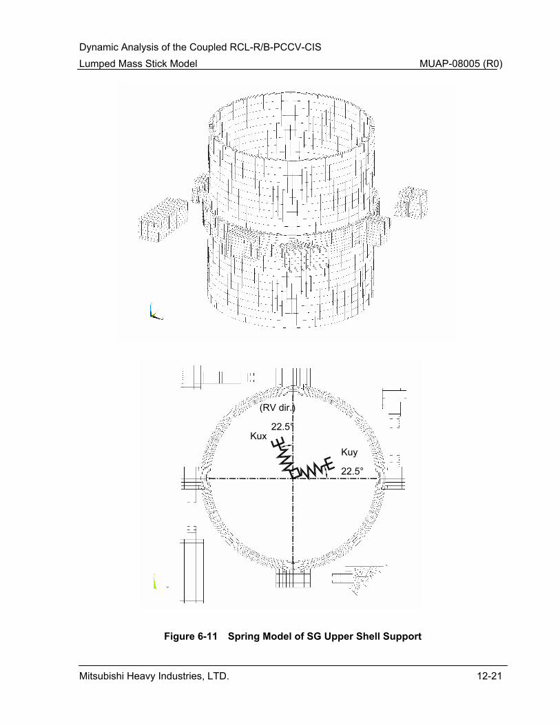
Dynamic Analysis of the Coupled RCL-R/B-PCCV-CIS Lumped Mass Stick Model MUAP-08005 (R0)
Mitsubishi Heavy Industries, LTD. 12-21
Figure 6-11 Spring Model of SG Upper Shell Support
(RV dir.)
22.5°
22.5°
Kuy
Kux

Dynamic Analysis of the Coupled RCL-R/B-PCCV-CIS Lumped Mass Stick Model MUAP-08005 (R0)
Mitsubishi Heavy Industries, LTD. 12-22
Figure 6-12 Spring Model of SG Intermediate Shell Support
(RV dir.)
Kmy
Kmx
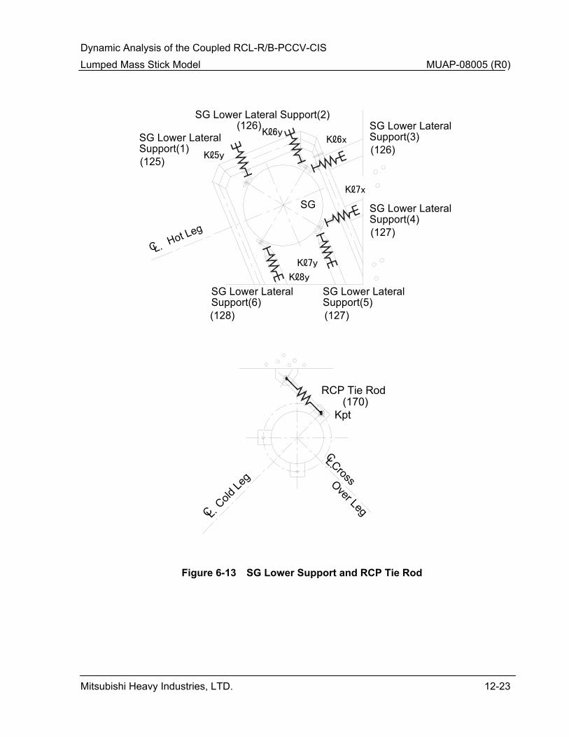
Dynamic Analysis of the Coupled RCL-R/B-PCCV-CIS Lumped Mass Stick Model MUAP-08005 (R0)
Mitsubishi Heavy Industries, LTD. 12-23
Figure 6-13 SG Lower Support and RCP Tie Rod
Cold Le
g
CL.
Cross
CL.
Over Leg
RCP Tie Rod(170)
Kpt
SG
Hot Leg
CL.
SG Lower Lateral Support(2)(126)
Support(1)SG Lower Lateral
(125)
Support(3)SG Lower Lateral
(126)
Support(4)SG Lower Lateral
(127)
Support(5)SG Lower Lateral
(127)Support(6)SG Lower Lateral
(128)
Kℓ5y
Kℓ6yKℓ6x
Kℓ7x
Kℓ7y
Kℓ8y

Dynamic Analysis of the Coupled RCL-R/B-PCCV-CIS Lumped Mass Stick Model MUAP-08005 (R0)
Mitsubishi Heavy Industries, LTD. 12-24
Figure 6-14 Configuration of SG Lower Supports and RCP Supports
Start Point
Support
4127
4768
LOOP-A
SG Lower Support
LOOP-B
LOOP-D
LOOP-C
4128
4769
4170
48116811
6170
6766
6126
6767
6127
67616760
6125
87698768
8767
8766
8127 8128
8170
8811 2811
2170
2761
2126
2125
27608126
RCP Lower Support
Steam Generator
Reactor Coolant Pump
Hot Leg
Cold Leg
Cross Over Leg
Global Coordinate Systems
PN
YZ
X

Dynamic Analysis of the Coupled RCL-R/B-PCCV-CIS Lumped Mass Stick Model MUAP-08005 (R0)
Mitsubishi Heavy Industries, LTD. 12-25
0.0
0.5
1.0
1.5
2.0
2.5
3.0
0.1 1 10 100
Frequency(Hz)
Acce
lera
tion(
g)SoftMedium1Medium2HardRockBROADENED
CV01 EL 25'-3"
PCCV
NS5% Damping
Figure 8-1 ISRS of PCCV (NS-Direction)
(Sheet 1 of 33)
0.0
0.5
1.0
1.5
2.0
2.5
3.0
3.5
0.1 1 10 100
Frequency(Hz)
Acce
lera
tion(
g)
SoftMedium1Medium2HardRockBROADENED
CV02 EL 50'-2"
PCCV
NS5% Damping
Figure 8-1 ISRS of PCCV (NS-Direction)
(Sheet 2 of 33)
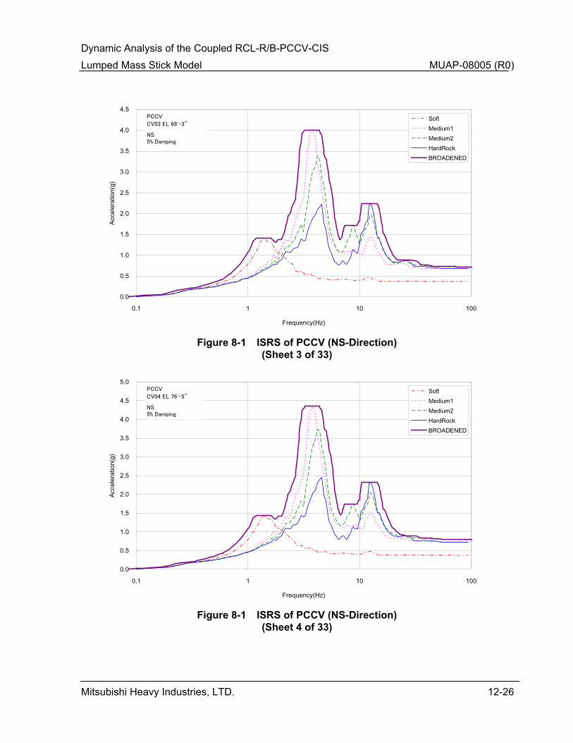
Dynamic Analysis of the Coupled RCL-R/B-PCCV-CIS Lumped Mass Stick Model MUAP-08005 (R0)
Mitsubishi Heavy Industries, LTD. 12-26
0.0
0.5
1.0
1.5
2.0
2.5
3.0
3.5
4.0
4.5
0.1 1 10 100
Frequency(Hz)
Acce
lera
tion(
g)SoftMedium1Medium2HardRockBROADENED
CV03 EL 68'-3"
PCCV
NS5% Damping
Figure 8-1 ISRS of PCCV (NS-Direction)
(Sheet 3 of 33)
0.0
0.5
1.0
1.5
2.0
2.5
3.0
3.5
4.0
4.5
5.0
0.1 1 10 100
Frequency(Hz)
Acce
lera
tion(
g)
SoftMedium1Medium2HardRockBROADENED
CV04 EL 76'-5"
PCCV
NS5% Damping
Figure 8-1 ISRS of PCCV (NS-Direction)
(Sheet 4 of 33)
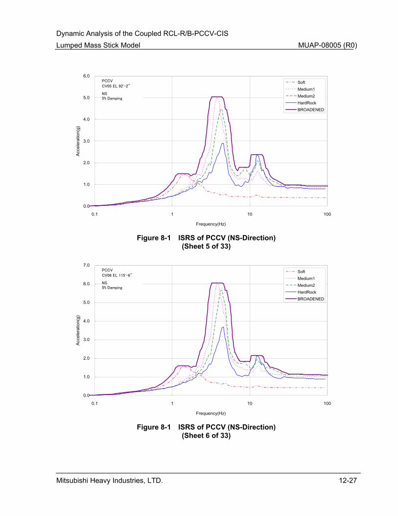
Dynamic Analysis of the Coupled RCL-R/B-PCCV-CIS Lumped Mass Stick Model MUAP-08005 (R0)
Mitsubishi Heavy Industries, LTD. 12-27
0.0
1.0
2.0
3.0
4.0
5.0
6.0
0.1 1 10 100
Frequency(Hz)
Acce
lera
tion(
g)SoftMedium1Medium2HardRockBROADENED
CV05 EL 92'-2"
PCCV
NS5% Damping
Figure 8-1 ISRS of PCCV (NS-Direction)
(Sheet 5 of 33)
0.0
1.0
2.0
3.0
4.0
5.0
6.0
7.0
0.1 1 10 100
Frequency(Hz)
Acce
lera
tion(
g)
SoftMedium1Medium2HardRockBROADENED
CV06 EL 115'-6"
PCCV
NS5% Damping
Figure 8-1 ISRS of PCCV (NS-Direction)
(Sheet 6 of 33)
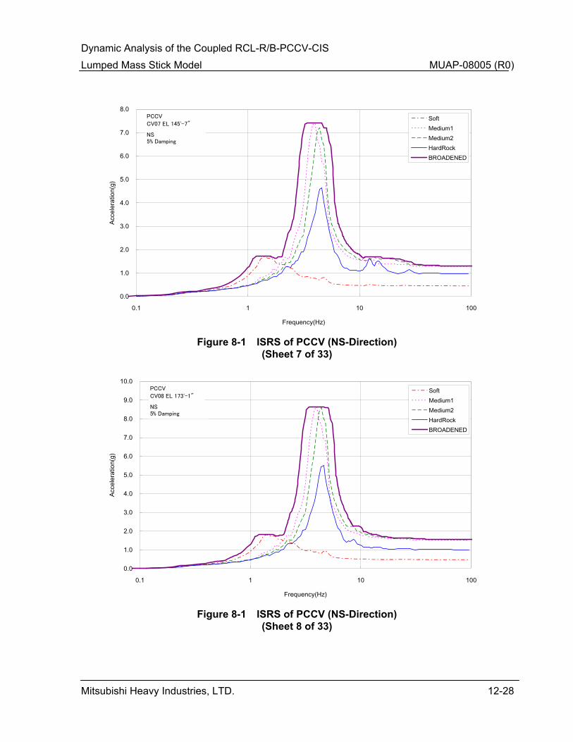
Dynamic Analysis of the Coupled RCL-R/B-PCCV-CIS Lumped Mass Stick Model MUAP-08005 (R0)
Mitsubishi Heavy Industries, LTD. 12-28
0.0
1.0
2.0
3.0
4.0
5.0
6.0
7.0
8.0
0.1 1 10 100
Frequency(Hz)
Acce
lera
tion(
g)SoftMedium1Medium2HardRockBROADENED
CV07 EL 145'-7"
PCCV
NS5% Damping
Figure 8-1 ISRS of PCCV (NS-Direction)
(Sheet 7 of 33)
0.0
1.0
2.0
3.0
4.0
5.0
6.0
7.0
8.0
9.0
10.0
0.1 1 10 100
Frequency(Hz)
Acce
lera
tion(
g)
SoftMedium1Medium2HardRockBROADENED
CV08 EL 173'-1"
PCCV
NS5% Damping
Figure 8-1 ISRS of PCCV (NS-Direction)
(Sheet 8 of 33)
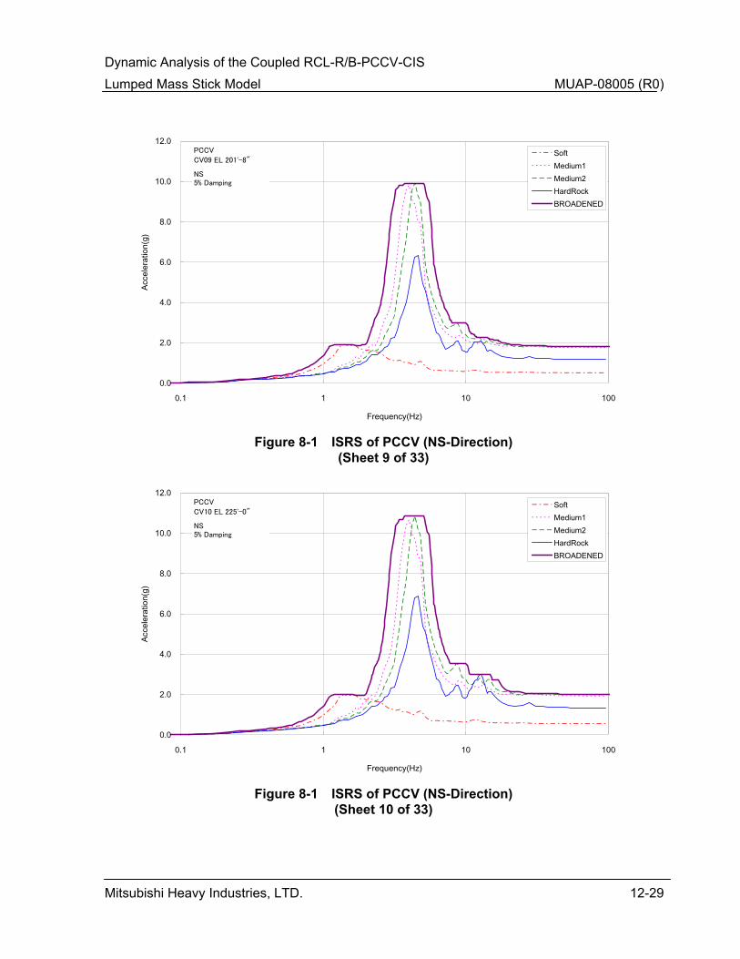
Dynamic Analysis of the Coupled RCL-R/B-PCCV-CIS Lumped Mass Stick Model MUAP-08005 (R0)
Mitsubishi Heavy Industries, LTD. 12-29
0.0
2.0
4.0
6.0
8.0
10.0
12.0
0.1 1 10 100
Frequency(Hz)
Acce
lera
tion(
g)SoftMedium1Medium2HardRockBROADENED
CV09 EL 201'-8"
PCCV
NS5% Damping
Figure 8-1 ISRS of PCCV (NS-Direction)
(Sheet 9 of 33)
0.0
2.0
4.0
6.0
8.0
10.0
12.0
0.1 1 10 100
Frequency(Hz)
Acce
lera
tion(
g)
SoftMedium1Medium2HardRockBROADENED
CV10 EL 225'-0"
PCCV
NS5% Damping
Figure 8-1 ISRS of PCCV (NS-Direction)
(Sheet 10 of 33)

Dynamic Analysis of the Coupled RCL-R/B-PCCV-CIS Lumped Mass Stick Model MUAP-08005 (R0)
Mitsubishi Heavy Industries, LTD. 12-30
0.0
2.0
4.0
6.0
8.0
10.0
12.0
0.1 1 10 100
Frequency(Hz)
Acce
lera
tion(
g)SoftMedium1Medium2HardRockBROADENED
CV11 EL 230'-2"
PCCV
NS5% Damping
Figure 8-1 ISRS of PCCV (NS-Direction)
(Sheet 11 of 33)
0.0
0.2
0.4
0.6
0.8
1.0
1.2
1.4
1.6
1.8
2.0
0.1 1 10 100
Frequency(Hz)
Acce
lera
tion(
g)
SoftMedium1Medium2HardRockBROADENED
IC01 EL 16'-0"
CIS
NS5% Damping
Figure 8-1 ISRS of CIS (NS-Direction)
(Sheet 12 of 33)
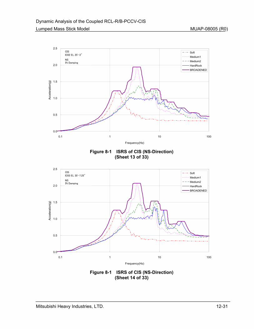
Dynamic Analysis of the Coupled RCL-R/B-PCCV-CIS Lumped Mass Stick Model MUAP-08005 (R0)
Mitsubishi Heavy Industries, LTD. 12-31
0.0
0.5
1.0
1.5
2.0
2.5
0.1 1 10 100
Frequency(Hz)
Acce
lera
tion(
g)SoftMedium1Medium2HardRockBROADENED
IC02 EL 25'-3"
CIS
NS5% Damping
Figure 8-1 ISRS of CIS (NS-Direction)
(Sheet 13 of 33)
0.0
0.5
1.0
1.5
2.0
2.5
0.1 1 10 100
Frequency(Hz)
Acce
lera
tion(
g)
SoftMedium1Medium2HardRockBROADENED
IC03 EL 35'-7.25"
CIS
NS5% Damping
Figure 8-1 ISRS of CIS (NS-Direction)
(Sheet 14 of 33)
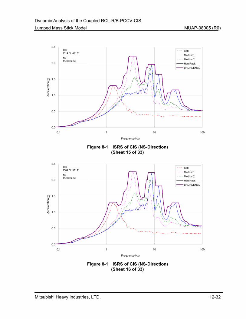
Dynamic Analysis of the Coupled RCL-R/B-PCCV-CIS Lumped Mass Stick Model MUAP-08005 (R0)
Mitsubishi Heavy Industries, LTD. 12-32
0.0
0.5
1.0
1.5
2.0
2.5
0.1 1 10 100
Frequency(Hz)
Acce
lera
tion(
g)SoftMedium1Medium2HardRockBROADENED
IC14 EL 45'-8"
CIS
NS5% Damping
Figure 8-1 ISRS of CIS (NS-Direction)
(Sheet 15 of 33)
0.0
0.5
1.0
1.5
2.0
2.5
0.1 1 10 100
Frequency(Hz)
Acce
lera
tion(
g)
SoftMedium1Medium2HardRockBROADENED
IC04 EL 50'-2"
CIS
NS5% Damping
Figure 8-1 ISRS of CIS (NS-Direction)
(Sheet 16 of 33)
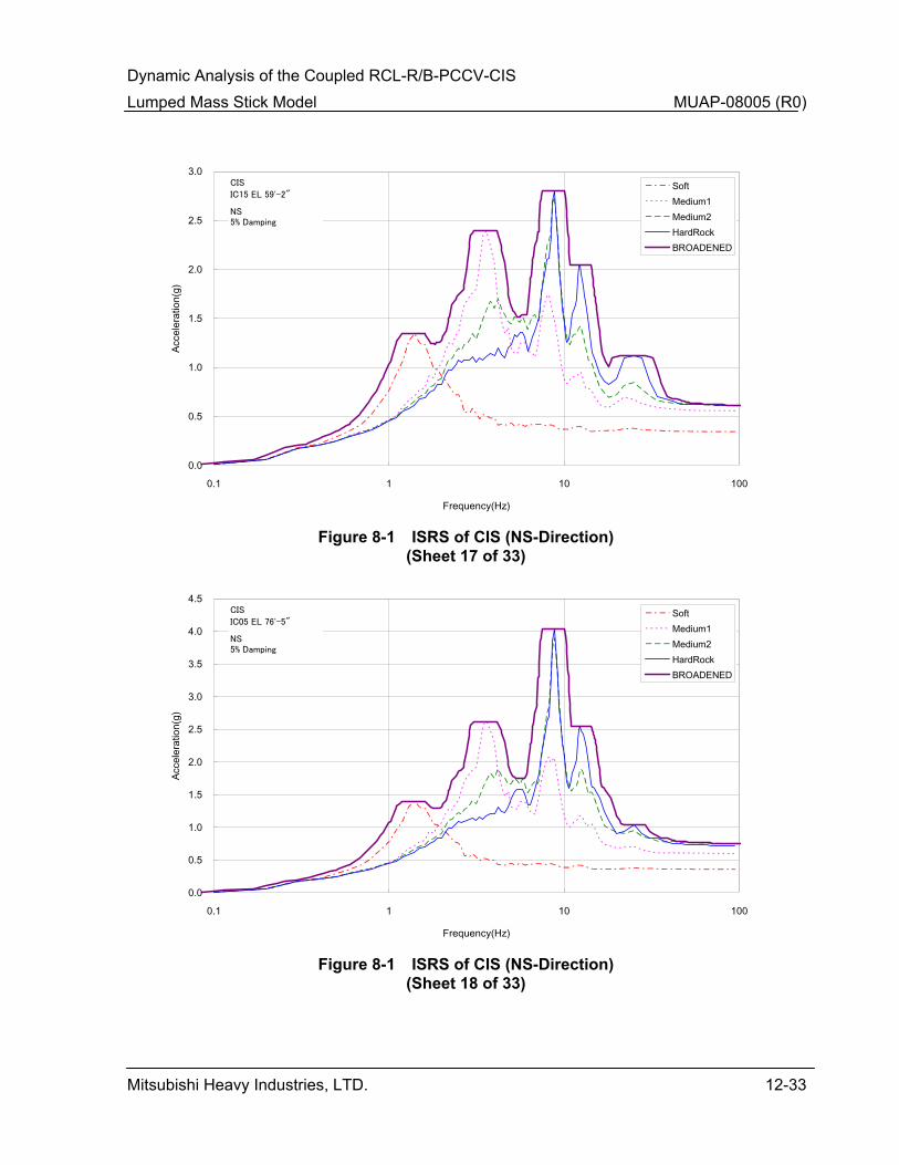
Dynamic Analysis of the Coupled RCL-R/B-PCCV-CIS Lumped Mass Stick Model MUAP-08005 (R0)
Mitsubishi Heavy Industries, LTD. 12-33
0.0
0.5
1.0
1.5
2.0
2.5
3.0
0.1 1 10 100
Frequency(Hz)
Acce
lera
tion(
g)SoftMedium1Medium2HardRockBROADENED
IC15 EL 59'-2"
CIS
NS5% Damping
Figure 8-1 ISRS of CIS (NS-Direction)
(Sheet 17 of 33)
0.0
0.5
1.0
1.5
2.0
2.5
3.0
3.5
4.0
4.5
0.1 1 10 100
Frequency(Hz)
Acce
lera
tion(
g)
SoftMedium1Medium2HardRockBROADENED
IC05 EL 76'-5"
CIS
NS5% Damping
Figure 8-1 ISRS of CIS (NS-Direction)
(Sheet 18 of 33)

Dynamic Analysis of the Coupled RCL-R/B-PCCV-CIS Lumped Mass Stick Model MUAP-08005 (R0)
Mitsubishi Heavy Industries, LTD. 12-34
0.0
1.0
2.0
3.0
4.0
5.0
6.0
0.1 1 10 100
Frequency(Hz)
Acce
lera
tion(
g)SoftMedium1Medium2HardRockBROADENED
IC61 EL 96'-7"
CIS
NS5% Damping
Figure 8-1 ISRS of CIS (NS-Direction)
(Sheet 19 of 33)
0.0
1.0
2.0
3.0
4.0
5.0
6.0
0.1 1 10 100
Frequency(Hz)
Acce
lera
tion(
g)
SoftMedium1Medium2HardRockBROADENED
IC62 EL 96'-7"
CIS
NS5% Damping
Figure 8-1 ISRS of CIS (NS-Direction)
(Sheet 20 of 33)

Dynamic Analysis of the Coupled RCL-R/B-PCCV-CIS Lumped Mass Stick Model MUAP-08005 (R0)
Mitsubishi Heavy Industries, LTD. 12-35
0.0
1.0
2.0
3.0
4.0
5.0
6.0
7.0
8.0
9.0
0.1 1 10 100
Frequency(Hz)
Acce
lera
tion(
g)SoftMedium1Medium2HardRockBROADENED
IC18 EL 110'-9"
CIS
NS5% Damping
Figure 8-1 ISRS of CIS (NS-Direction)
(Sheet 21 of 33)
0.0
1.0
2.0
3.0
4.0
5.0
6.0
7.0
8.0
9.0
10.0
0.1 1 10 100
Frequency(Hz)
Acce
lera
tion(
g)
SoftMedium1Medium2HardRockBROADENED
IC08 EL 112'-4"
CIS
NS5% Damping
Figure 8-1 ISRS of CIS (NS-Direction)
(Sheet 22 of 33)
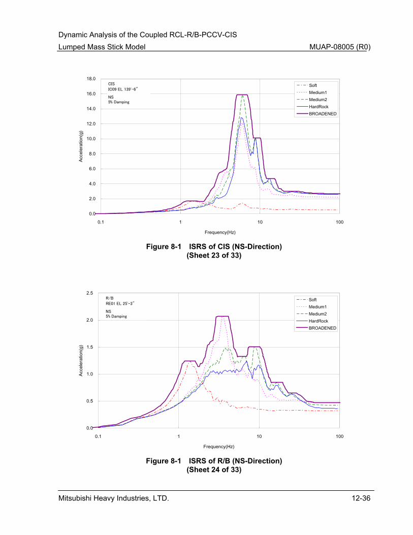
Dynamic Analysis of the Coupled RCL-R/B-PCCV-CIS Lumped Mass Stick Model MUAP-08005 (R0)
Mitsubishi Heavy Industries, LTD. 12-36
0.0
2.0
4.0
6.0
8.0
10.0
12.0
14.0
16.0
18.0
0.1 1 10 100
Frequency(Hz)
Acce
lera
tion(
g)SoftMedium1Medium2HardRockBROADENED
IC09 EL 139'-6"
CIS
NS5% Damping
Figure 8-1 ISRS of CIS (NS-Direction)
(Sheet 23 of 33)
0.0
0.5
1.0
1.5
2.0
2.5
0.1 1 10 100
Frequency(Hz)
Acce
lera
tion(
g)
SoftMedium1Medium2HardRockBROADENED
RE01 EL 25'-3"
R/B
NS5% Damping
Figure 8-1 ISRS of R/B (NS-Direction)
(Sheet 24 of 33)
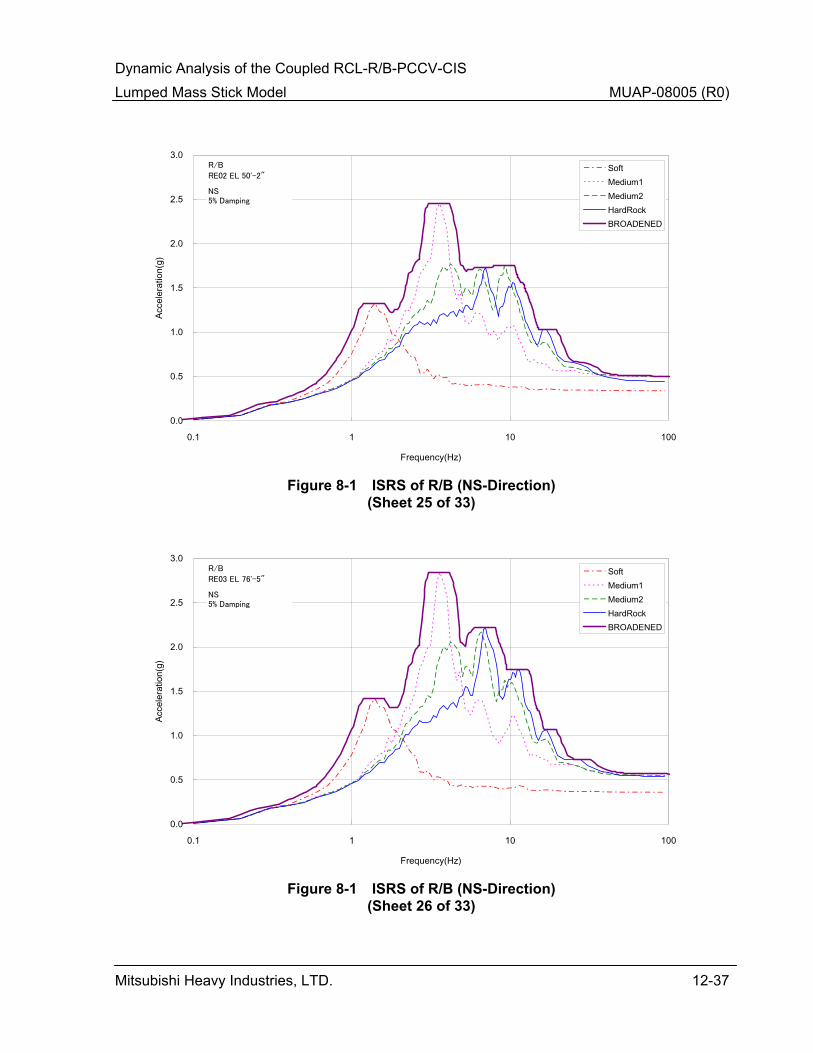
Dynamic Analysis of the Coupled RCL-R/B-PCCV-CIS Lumped Mass Stick Model MUAP-08005 (R0)
Mitsubishi Heavy Industries, LTD. 12-37
0.0
0.5
1.0
1.5
2.0
2.5
3.0
0.1 1 10 100
Frequency(Hz)
Acce
lera
tion(
g)SoftMedium1Medium2HardRockBROADENED
RE02 EL 50'-2"
R/B
NS5% Damping
Figure 8-1 ISRS of R/B (NS-Direction)
(Sheet 25 of 33)
0.0
0.5
1.0
1.5
2.0
2.5
3.0
0.1 1 10 100
Frequency(Hz)
Acce
lera
tion(
g)
SoftMedium1Medium2HardRockBROADENED
RE03 EL 76'-5"
R/B
NS5% Damping
Figure 8-1 ISRS of R/B (NS-Direction)
(Sheet 26 of 33)
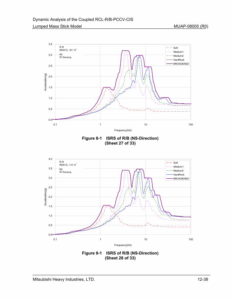
Dynamic Analysis of the Coupled RCL-R/B-PCCV-CIS Lumped Mass Stick Model MUAP-08005 (R0)
Mitsubishi Heavy Industries, LTD. 12-38
0.0
0.5
1.0
1.5
2.0
2.5
3.0
3.5
0.1 1 10 100
Frequency(Hz)
Acce
lera
tion(
g)SoftMedium1Medium2HardRockBROADENED
RE04 EL 101'-0"
R/B
NS5% Damping
Figure 8-1 ISRS of R/B (NS-Direction)
(Sheet 27 of 33)
0.0
0.5
1.0
1.5
2.0
2.5
3.0
3.5
4.0
0.1 1 10 100
Frequency(Hz)
Acce
lera
tion(
g)
SoftMedium1Medium2HardRockBROADENED
RE05 EL 115'-6"
R/B
NS5% Damping
Figure 8-1 ISRS of R/B (NS-Direction)
(Sheet 28 of 33)

Dynamic Analysis of the Coupled RCL-R/B-PCCV-CIS Lumped Mass Stick Model MUAP-08005 (R0)
Mitsubishi Heavy Industries, LTD. 12-39
0.0
0.5
1.0
1.5
2.0
2.5
3.0
3.5
0.1 1 10 100
Frequency(Hz)
Acce
lera
tion(
g)SoftMedium1Medium2HardRockBROADENED
RE41 EL 101'-0"
R/B
NS5% Damping
Figure 8-1 ISRS of R/B (NS-Direction)
(Sheet 29 of 33)
0.0
0.5
1.0
1.5
2.0
2.5
3.0
3.5
0.1 1 10 100
Frequency(Hz)
Acce
lera
tion(
g)
SoftMedium1Medium2HardRockBROADENED
RE42 EL 101'-0"
R/B
NS5% Damping
Figure 8-1 ISRS of R/B (NS-Direction)
(Sheet 30 of 33)
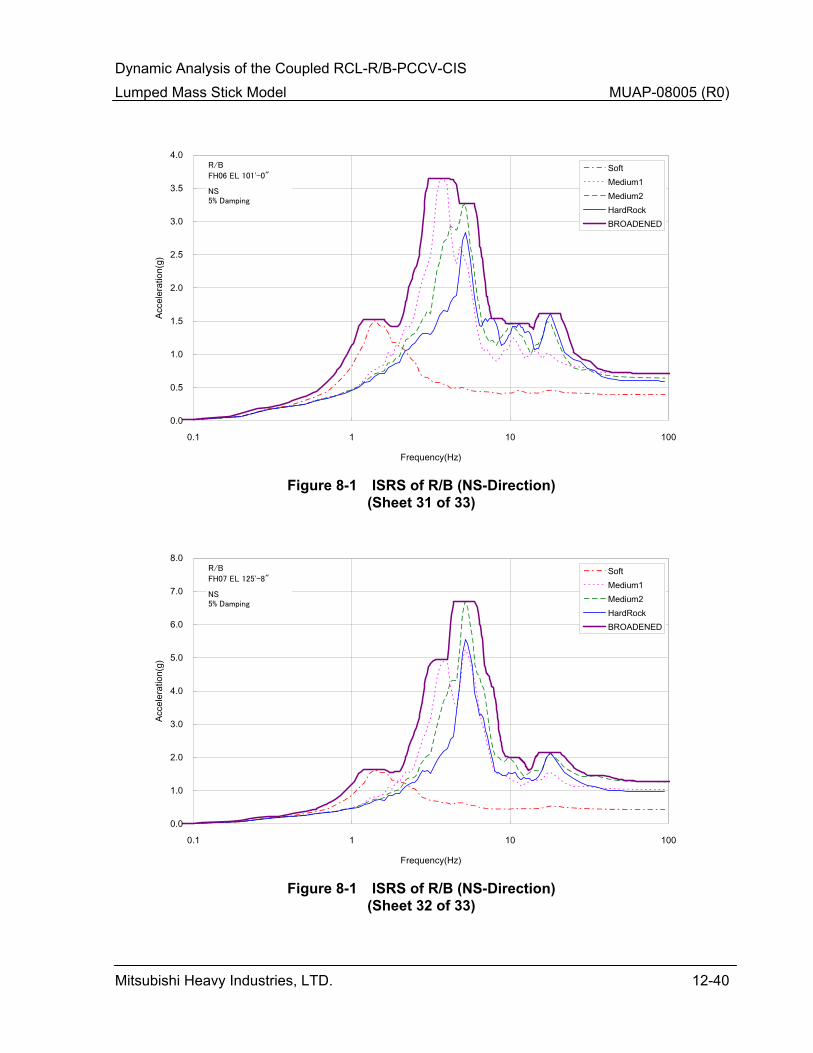
Dynamic Analysis of the Coupled RCL-R/B-PCCV-CIS Lumped Mass Stick Model MUAP-08005 (R0)
Mitsubishi Heavy Industries, LTD. 12-40
0.0
0.5
1.0
1.5
2.0
2.5
3.0
3.5
4.0
0.1 1 10 100
Frequency(Hz)
Acce
lera
tion(
g)SoftMedium1Medium2HardRockBROADENED
FH06 EL 101'-0"
R/B
NS5% Damping
Figure 8-1 ISRS of R/B (NS-Direction)
(Sheet 31 of 33)
0.0
1.0
2.0
3.0
4.0
5.0
6.0
7.0
8.0
0.1 1 10 100
Frequency(Hz)
Acce
lera
tion(
g)
SoftMedium1Medium2HardRockBROADENED
FH07 EL 125'-8"
R/B
NS5% Damping
Figure 8-1 ISRS of R/B (NS-Direction)
(Sheet 32 of 33)

Dynamic Analysis of the Coupled RCL-R/B-PCCV-CIS Lumped Mass Stick Model MUAP-08005 (R0)
Mitsubishi Heavy Industries, LTD. 12-41
0.0
2.0
4.0
6.0
8.0
10.0
12.0
14.0
0.1 1 10 100
Frequency(Hz)
Acce
lera
tion(
g)SoftMedium1Medium2HardRockBROADENED
FH08 EL 154'-6"
R/B
NS5% Damping
Figure 8-1 ISRS of R/B (NS-Direction)
(Sheet 33 of 33)

Dynamic Analysis of the Coupled RCL-R/B-PCCV-CIS Lumped Mass Stick Model MUAP-08005 (R0)
Mitsubishi Heavy Industries, LTD. 12-42
0.0
0.5
1.0
1.5
2.0
2.5
0.1 1 10 100
Frequency(Hz)
Acce
lera
tion(
g)SoftMedium1Medium2HardRockBROADENED
CV01 EL 25'-3"
PCCV
EW5% Damping
Figure 8-2 ISRS of PCCV (EW-Direction)
(Sheet 1 of 33)
0.0
0.5
1.0
1.5
2.0
2.5
3.0
3.5
0.1 1 10 100
Frequency(Hz)
Acce
lera
tion(
g)
SoftMedium1Medium2HardRockBROADENED
CV02 EL 50'-2"
PCCV
EW5% Damping
Figure 8-2 ISRS of PCCV (EW-Direction)
(Sheet 2 of 33)

Dynamic Analysis of the Coupled RCL-R/B-PCCV-CIS Lumped Mass Stick Model MUAP-08005 (R0)
Mitsubishi Heavy Industries, LTD. 12-43
0.0
0.5
1.0
1.5
2.0
2.5
3.0
3.5
4.0
4.5
0.1 1 10 100
Frequency(Hz)
Acce
lera
tion(
g)SoftMedium1Medium2HardRockBROADENED
CV03 EL 68'-3"
PCCV
EW5% Damping
Figure 8-2 ISRS of PCCV (EW-Direction)
(Sheet 3 of 33)
0.0
0.5
1.0
1.5
2.0
2.5
3.0
3.5
4.0
4.5
5.0
0.1 1 10 100
Frequency(Hz)
Acce
lera
tion(
g)
SoftMedium1Medium2HardRockBROADENED
CV04 EL 76'-5"
PCCV
EW5% Damping
Figure 8-2 ISRS of PCCV (EW-Direction)
(Sheet 4 of 33)
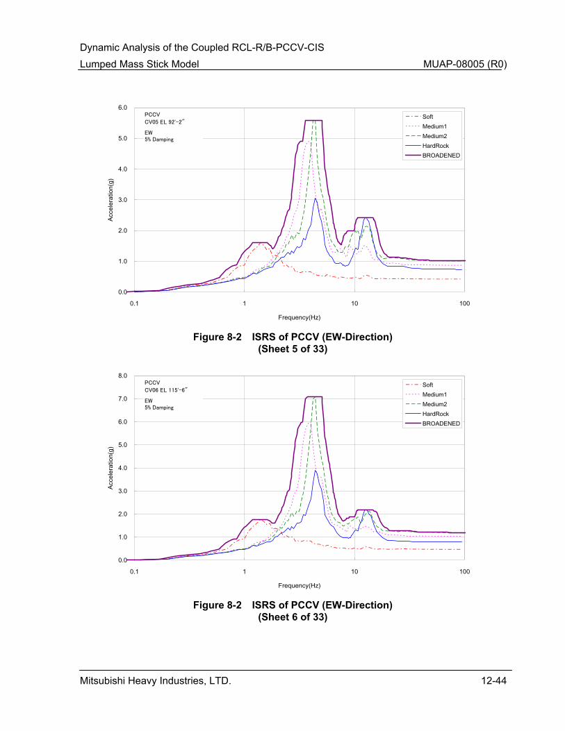
Dynamic Analysis of the Coupled RCL-R/B-PCCV-CIS Lumped Mass Stick Model MUAP-08005 (R0)
Mitsubishi Heavy Industries, LTD. 12-44
0.0
1.0
2.0
3.0
4.0
5.0
6.0
0.1 1 10 100
Frequency(Hz)
Acce
lera
tion(
g)SoftMedium1Medium2HardRockBROADENED
CV05 EL 92'-2"
PCCV
EW5% Damping
Figure 8-2 ISRS of PCCV (EW-Direction)
(Sheet 5 of 33)
0.0
1.0
2.0
3.0
4.0
5.0
6.0
7.0
8.0
0.1 1 10 100
Frequency(Hz)
Acce
lera
tion(
g)
SoftMedium1Medium2HardRockBROADENED
CV06 EL 115'-6"
PCCV
EW5% Damping
Figure 8-2 ISRS of PCCV (EW-Direction)
(Sheet 6 of 33)
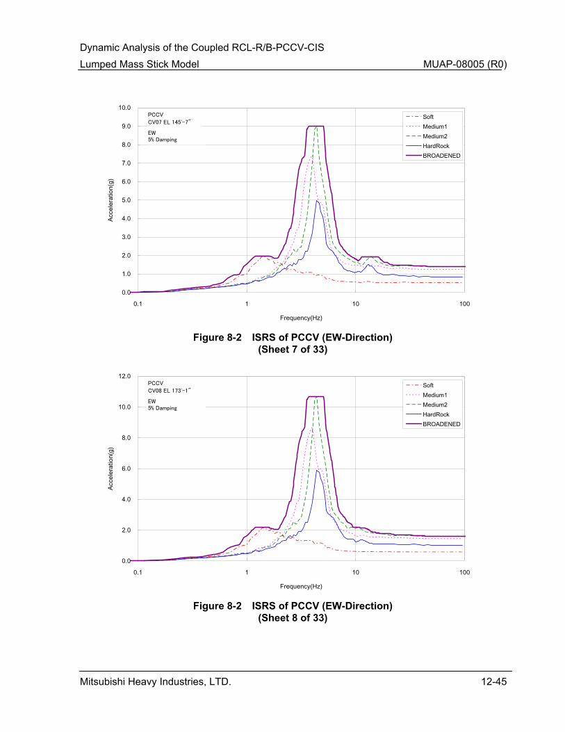
Dynamic Analysis of the Coupled RCL-R/B-PCCV-CIS Lumped Mass Stick Model MUAP-08005 (R0)
Mitsubishi Heavy Industries, LTD. 12-45
0.0
1.0
2.0
3.0
4.0
5.0
6.0
7.0
8.0
9.0
10.0
0.1 1 10 100
Frequency(Hz)
Acce
lera
tion(
g)SoftMedium1Medium2HardRockBROADENED
CV07 EL 145'-7"
PCCV
EW5% Damping
Figure 8-2 ISRS of PCCV (EW-Direction)
(Sheet 7 of 33)
0.0
2.0
4.0
6.0
8.0
10.0
12.0
0.1 1 10 100
Frequency(Hz)
Acce
lera
tion(
g)
SoftMedium1Medium2HardRockBROADENED
CV08 EL 173'-1"
PCCV
EW5% Damping
Figure 8-2 ISRS of PCCV (EW-Direction)
(Sheet 8 of 33)
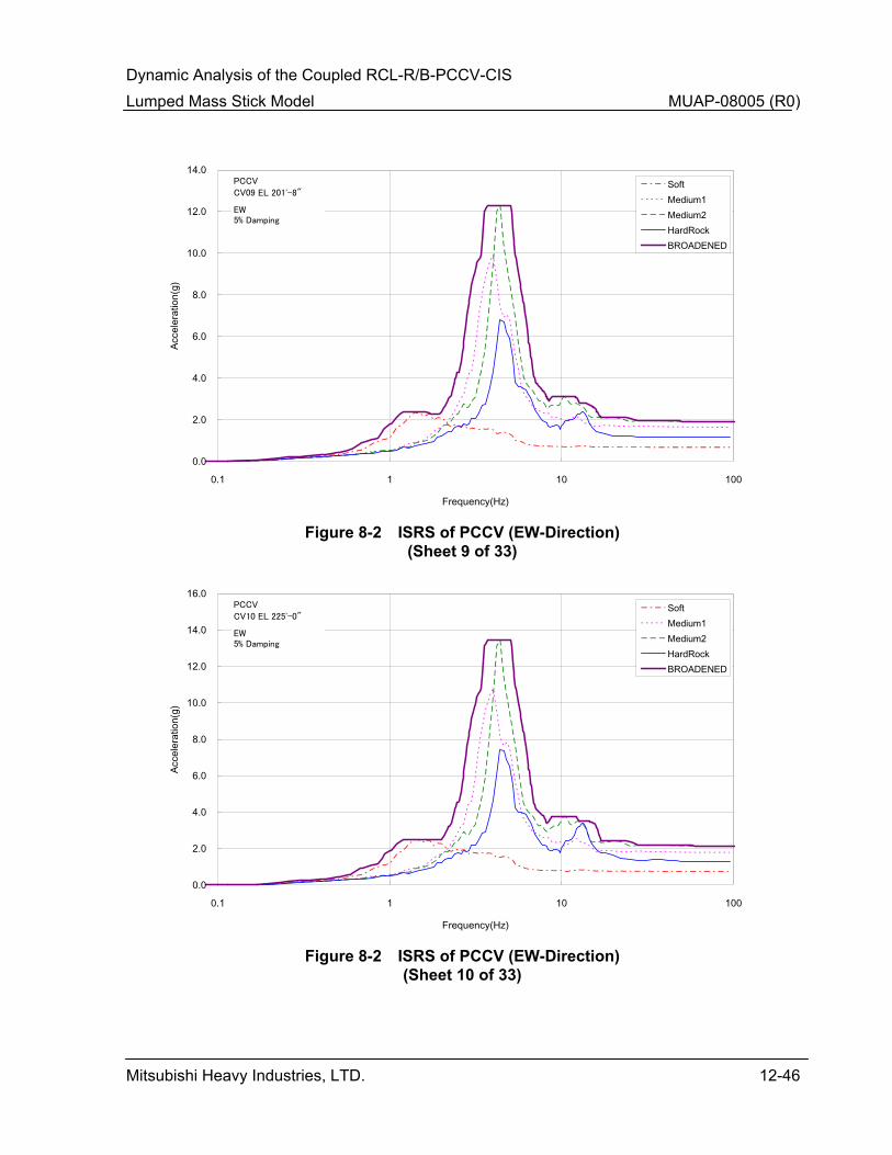
Dynamic Analysis of the Coupled RCL-R/B-PCCV-CIS Lumped Mass Stick Model MUAP-08005 (R0)
Mitsubishi Heavy Industries, LTD. 12-46
0.0
2.0
4.0
6.0
8.0
10.0
12.0
14.0
0.1 1 10 100
Frequency(Hz)
Acce
lera
tion(
g)SoftMedium1Medium2HardRockBROADENED
CV09 EL 201'-8"
PCCV
EW5% Damping
Figure 8-2 ISRS of PCCV (EW-Direction)
(Sheet 9 of 33)
0.0
2.0
4.0
6.0
8.0
10.0
12.0
14.0
16.0
0.1 1 10 100
Frequency(Hz)
Acce
lera
tion(
g)
SoftMedium1Medium2HardRockBROADENED
CV10 EL 225'-0"
PCCV
EW5% Damping
Figure 8-2 ISRS of PCCV (EW-Direction)
(Sheet 10 of 33)
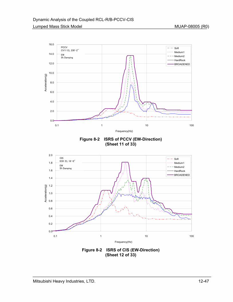
Dynamic Analysis of the Coupled RCL-R/B-PCCV-CIS Lumped Mass Stick Model MUAP-08005 (R0)
Mitsubishi Heavy Industries, LTD. 12-47
0.0
2.0
4.0
6.0
8.0
10.0
12.0
14.0
16.0
0.1 1 10 100
Frequency(Hz)
Acce
lera
tion(
g)SoftMedium1Medium2HardRockBROADENED
CV11 EL 230'-2"
PCCV
EW5% Damping
Figure 8-2 ISRS of PCCV (EW-Direction)
(Sheet 11 of 33)
0.0
0.2
0.4
0.6
0.8
1.0
1.2
1.4
1.6
1.8
2.0
0.1 1 10 100
Frequency(Hz)
Acce
lera
tion(
g)
SoftMedium1Medium2HardRockBROADENED
IC01 EL 16'-0"
CIS
EW5% Damping
Figure 8-2 ISRS of CIS (EW-Direction)
(Sheet 12 of 33)
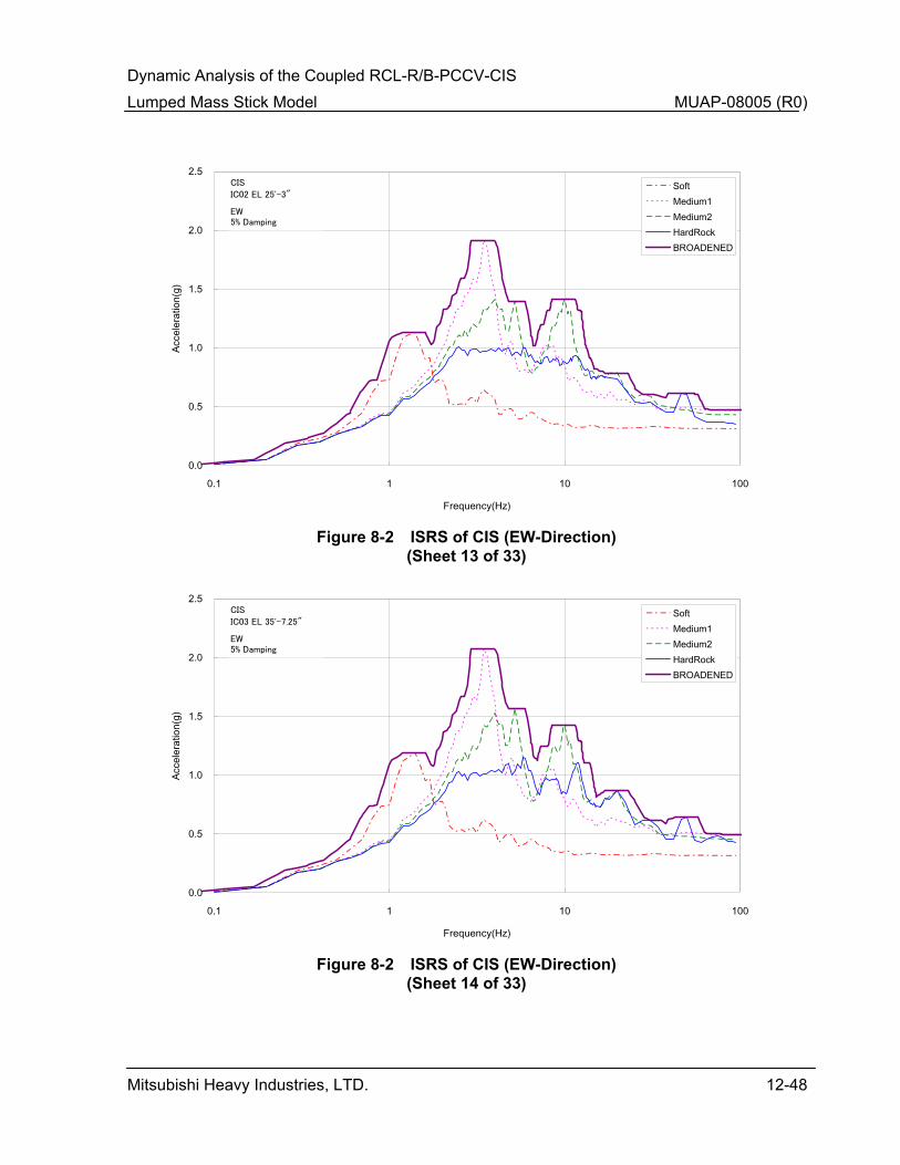
Dynamic Analysis of the Coupled RCL-R/B-PCCV-CIS Lumped Mass Stick Model MUAP-08005 (R0)
Mitsubishi Heavy Industries, LTD. 12-48
0.0
0.5
1.0
1.5
2.0
2.5
0.1 1 10 100
Frequency(Hz)
Acce
lera
tion(
g)SoftMedium1Medium2HardRockBROADENED
IC02 EL 25'-3"
CIS
EW5% Damping
Figure 8-2 ISRS of CIS (EW-Direction)
(Sheet 13 of 33)
0.0
0.5
1.0
1.5
2.0
2.5
0.1 1 10 100
Frequency(Hz)
Acce
lera
tion(
g)
SoftMedium1Medium2HardRockBROADENED
IC03 EL 35'-7.25"
CIS
EW5% Damping
Figure 8-2 ISRS of CIS (EW-Direction)
(Sheet 14 of 33)

Dynamic Analysis of the Coupled RCL-R/B-PCCV-CIS Lumped Mass Stick Model MUAP-08005 (R0)
Mitsubishi Heavy Industries, LTD. 12-49
0.0
0.5
1.0
1.5
2.0
2.5
0.1 1 10 100
Frequency(Hz)
Acce
lera
tion(
g)SoftMedium1Medium2HardRockBROADENED
IC14 EL 45'-8"
CIS
EW5% Damping
Figure 8-2 ISRS of CIS (EW-Direction)
(Sheet 15 of 33)
0.0
0.5
1.0
1.5
2.0
2.5
0.1 1 10 100
Frequency(Hz)
Acce
lera
tion(
g)
SoftMedium1Medium2HardRockBROADENED
IC04 EL 50'-2"
CIS
EW5% Damping
Figure 8-2 ISRS of CIS (EW-Direction)
(Sheet 16 of 33)

Dynamic Analysis of the Coupled RCL-R/B-PCCV-CIS Lumped Mass Stick Model MUAP-08005 (R0)
Mitsubishi Heavy Industries, LTD. 12-50
0.0
0.5
1.0
1.5
2.0
2.5
3.0
0.1 1 10 100
Frequency(Hz)
Acce
lera
tion(
g)SoftMedium1Medium2HardRockBROADENED
IC15 EL 59'-2"
CIS
EW5% Damping
Figure 8-2 ISRS of CIS (EW-Direction)
(Sheet 17 of 33)
0.0
0.5
1.0
1.5
2.0
2.5
3.0
3.5
0.1 1 10 100
Frequency(Hz)
Acce
lera
tion(
g)
SoftMedium1Medium2HardRockBROADENED
IC05 EL 76'-5"
CIS
EW5% Damping
Figure 8-2 ISRS of CIS (EW-Direction)
(Sheet 18 of 33)

Dynamic Analysis of the Coupled RCL-R/B-PCCV-CIS Lumped Mass Stick Model MUAP-08005 (R0)
Mitsubishi Heavy Industries, LTD. 12-51
0.0
0.5
1.0
1.5
2.0
2.5
3.0
3.5
4.0
4.5
0.1 1 10 100
Frequency(Hz)
Acce
lera
tion(
g)SoftMedium1Medium2HardRockBROADENED
IC61 EL 96'-7"
CIS
EW5% Damping
Figure 8-2 ISRS of CIS (EW-Direction)
(Sheet 19 of 33)
0.0
0.5
1.0
1.5
2.0
2.5
3.0
3.5
4.0
4.5
0.1 1 10 100
Frequency(Hz)
Acce
lera
tion(
g)
SoftMedium1Medium2HardRockBROADENED
IC62 EL 96'-7"
CIS
EW5% Damping
Figure 8-2 ISRS of CIS (EW-Direction)
(Sheet 20 of 33)
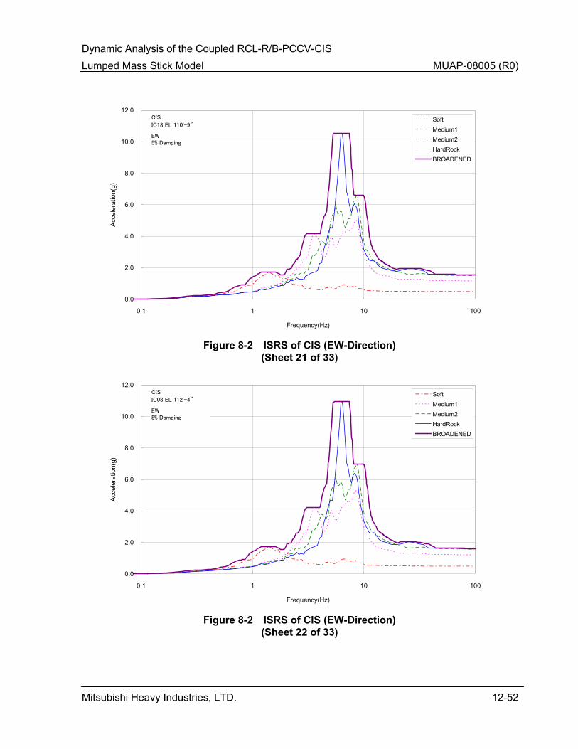
Dynamic Analysis of the Coupled RCL-R/B-PCCV-CIS Lumped Mass Stick Model MUAP-08005 (R0)
Mitsubishi Heavy Industries, LTD. 12-52
0.0
2.0
4.0
6.0
8.0
10.0
12.0
0.1 1 10 100
Frequency(Hz)
Acce
lera
tion(
g)SoftMedium1Medium2HardRockBROADENED
IC18 EL 110'-9"
CIS
EW5% Damping
Figure 8-2 ISRS of CIS (EW-Direction)
(Sheet 21 of 33)
0.0
2.0
4.0
6.0
8.0
10.0
12.0
0.1 1 10 100
Frequency(Hz)
Acce
lera
tion(
g)
SoftMedium1Medium2HardRockBROADENED
IC08 EL 112'-4"
CIS
EW5% Damping
Figure 8-2 ISRS of CIS (EW-Direction)
(Sheet 22 of 33)
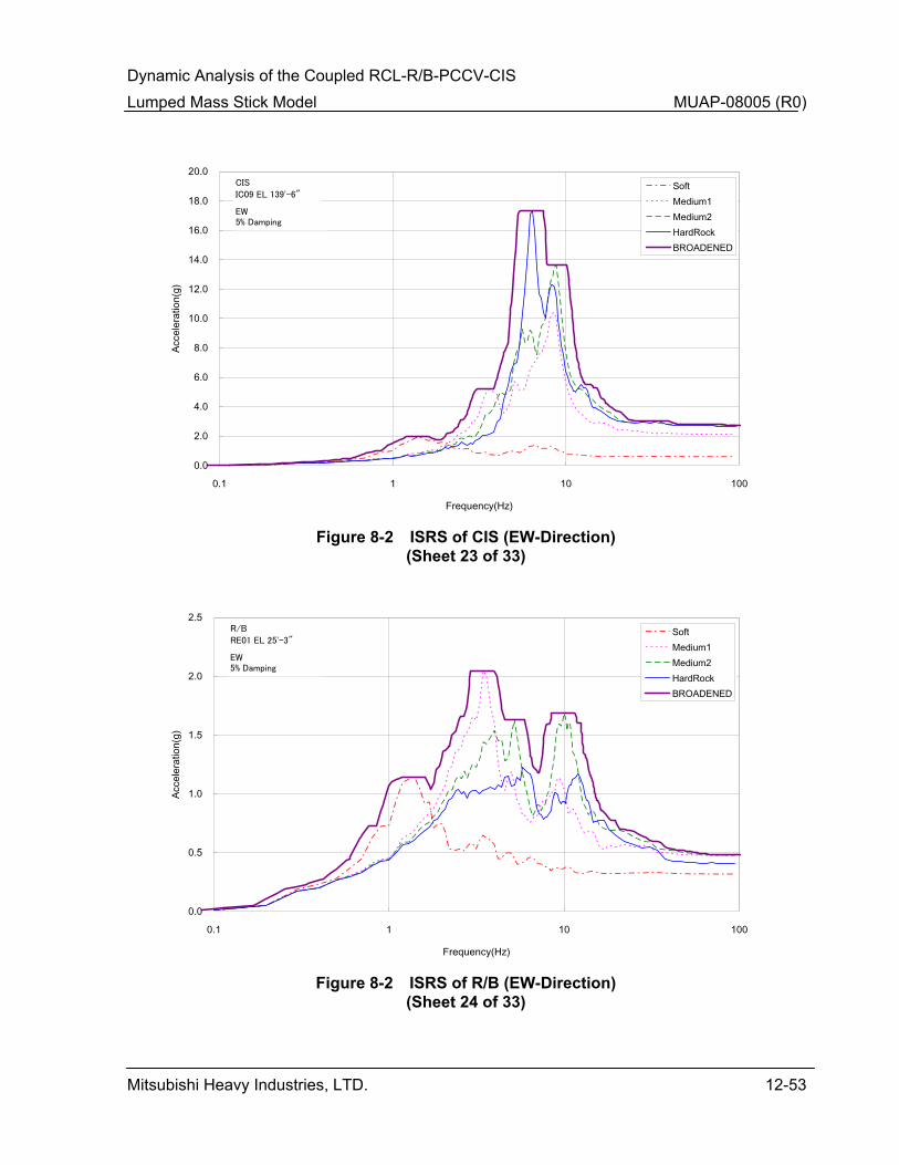
Dynamic Analysis of the Coupled RCL-R/B-PCCV-CIS Lumped Mass Stick Model MUAP-08005 (R0)
Mitsubishi Heavy Industries, LTD. 12-53
0.0
2.0
4.0
6.0
8.0
10.0
12.0
14.0
16.0
18.0
20.0
0.1 1 10 100
Frequency(Hz)
Acce
lera
tion(
g)SoftMedium1Medium2HardRockBROADENED
IC09 EL 139'-6"
CIS
EW5% Damping
Figure 8-2 ISRS of CIS (EW-Direction)
(Sheet 23 of 33)
0.0
0.5
1.0
1.5
2.0
2.5
0.1 1 10 100
Frequency(Hz)
Acce
lera
tion(
g)
SoftMedium1Medium2HardRockBROADENED
RE01 EL 25'-3"
R/B
EW5% Damping
Figure 8-2 ISRS of R/B (EW-Direction)
(Sheet 24 of 33)
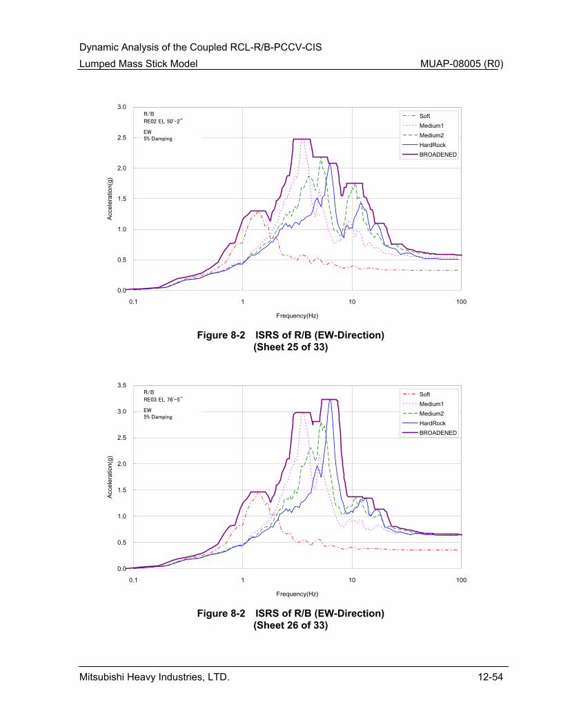
Dynamic Analysis of the Coupled RCL-R/B-PCCV-CIS Lumped Mass Stick Model MUAP-08005 (R0)
Mitsubishi Heavy Industries, LTD. 12-54
0.0
0.5
1.0
1.5
2.0
2.5
3.0
0.1 1 10 100
Frequency(Hz)
Acce
lera
tion(
g)SoftMedium1Medium2HardRockBROADENED
RE02 EL 50'-2"
R/B
EW5% Damping
Figure 8-2 ISRS of R/B (EW-Direction)
(Sheet 25 of 33)
0.0
0.5
1.0
1.5
2.0
2.5
3.0
3.5
0.1 1 10 100
Frequency(Hz)
Acce
lera
tion(
g)
SoftMedium1Medium2HardRockBROADENED
RE03 EL 76'-5"
R/B
EW5% Damping
Figure 8-2 ISRS of R/B (EW-Direction)
(Sheet 26 of 33)

Dynamic Analysis of the Coupled RCL-R/B-PCCV-CIS Lumped Mass Stick Model MUAP-08005 (R0)
Mitsubishi Heavy Industries, LTD. 12-55
0.0
1.0
2.0
3.0
4.0
5.0
6.0
0.1 1 10 100
Frequency(Hz)
Acce
lera
tion(
g)SoftMedium1Medium2HardRockBROADENED
RE04 EL 101'-0"
R/B
EW5% Damping
Figure 8-2 ISRS of R/B (EW-Direction)
(Sheet 27 of 33)
0.0
1.0
2.0
3.0
4.0
5.0
6.0
0.1 1 10 100
Frequency(Hz)
Acce
lera
tion(
g)
SoftMedium1Medium2HardRockBROADENED
RE05 EL 115'-6"
R/B
EW5% Damping
Figure 8-2 ISRS of R/B (EW-Direction)
(Sheet 28 of 33)
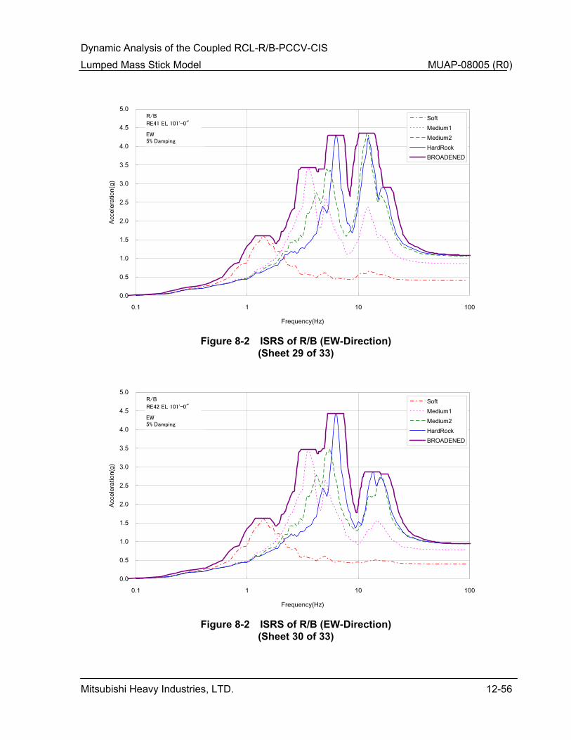
Dynamic Analysis of the Coupled RCL-R/B-PCCV-CIS Lumped Mass Stick Model MUAP-08005 (R0)
Mitsubishi Heavy Industries, LTD. 12-56
0.0
0.5
1.0
1.5
2.0
2.5
3.0
3.5
4.0
4.5
5.0
0.1 1 10 100
Frequency(Hz)
Acce
lera
tion(
g)SoftMedium1Medium2HardRockBROADENED
RE41 EL 101'-0"
R/B
EW5% Damping
Figure 8-2 ISRS of R/B (EW-Direction)
(Sheet 29 of 33)
0.0
0.5
1.0
1.5
2.0
2.5
3.0
3.5
4.0
4.5
5.0
0.1 1 10 100
Frequency(Hz)
Acce
lera
tion(
g)
SoftMedium1Medium2HardRockBROADENED
RE42 EL 101'-0"
R/B
EW5% Damping
Figure 8-2 ISRS of R/B (EW-Direction)
(Sheet 30 of 33)
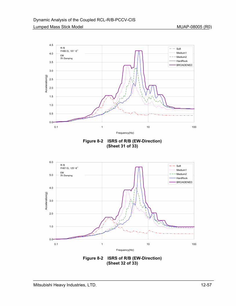
Dynamic Analysis of the Coupled RCL-R/B-PCCV-CIS Lumped Mass Stick Model MUAP-08005 (R0)
Mitsubishi Heavy Industries, LTD. 12-57
0.0
0.5
1.0
1.5
2.0
2.5
3.0
3.5
4.0
4.5
0.1 1 10 100
Frequency(Hz)
Acce
lera
tion(
g)SoftMedium1Medium2HardRockBROADENED
FH06 EL 101'-0"
R/B
EW5% Damping
Figure 8-2 ISRS of R/B (EW-Direction)
(Sheet 31 of 33)
0.0
1.0
2.0
3.0
4.0
5.0
6.0
0.1 1 10 100
Frequency(Hz)
Acce
lera
tion(
g)
SoftMedium1Medium2HardRockBROADENED
FH07 EL 125'-8"
R/B
EW5% Damping
Figure 8-2 ISRS of R/B (EW-Direction)
(Sheet 32 of 33)
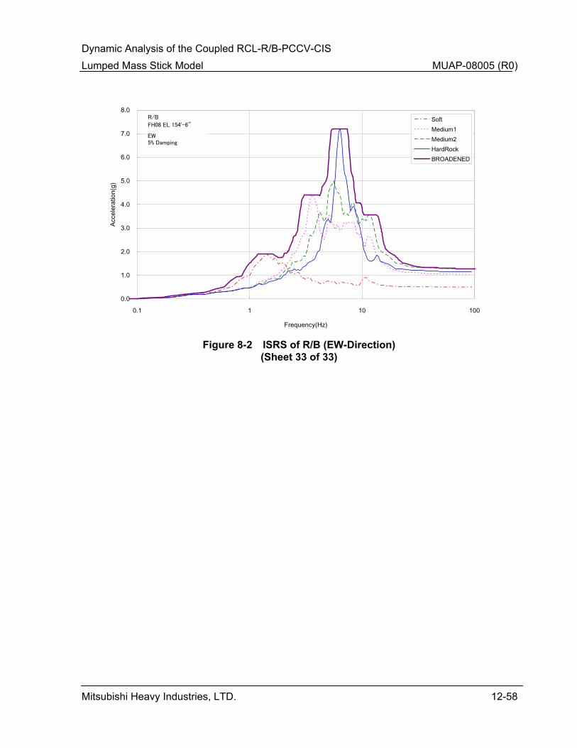
Dynamic Analysis of the Coupled RCL-R/B-PCCV-CIS Lumped Mass Stick Model MUAP-08005 (R0)
Mitsubishi Heavy Industries, LTD. 12-58
0.0
1.0
2.0
3.0
4.0
5.0
6.0
7.0
8.0
0.1 1 10 100
Frequency(Hz)
Acce
lera
tion(
g)SoftMedium1Medium2HardRockBROADENED
FH08 EL 154'-6"
R/B
EW5% Damping
Figure 8-2 ISRS of R/B (EW-Direction)
(Sheet 33 of 33)

Dynamic Analysis of the Coupled RCL-R/B-PCCV-CIS Lumped Mass Stick Model MUAP-08005 (R0)
Mitsubishi Heavy Industries, LTD. 12-59
0.0
0.2
0.4
0.6
0.8
1.0
1.2
1.4
1.6
1.8
0.1 1 10 100
Frequency(Hz)
Acce
lera
tion(
g)SoftMedium1Medium2HardRockBROADENED
CV01 EL 25'-3"
PCCV
Vert5% Damping
Figure 8-3 ISRS of PCCV (Vertical-Direction)
(Sheet 1 of 33)
0.0
0.5
1.0
1.5
2.0
2.5
0.1 1 10 100
Frequency(Hz)
Acce
lera
tion(
g)
SoftMedium1Medium2HardRockBROADENED
CV02 EL 50'-2"
PCCV
Vert5% Damping
Figure 8-3 ISRS of PCCV (Vertical-Direction)
(Sheet 2 of 33)

Dynamic Analysis of the Coupled RCL-R/B-PCCV-CIS Lumped Mass Stick Model MUAP-08005 (R0)
Mitsubishi Heavy Industries, LTD. 12-60
0.0
0.5
1.0
1.5
2.0
2.5
3.0
0.1 1 10 100
Frequency(Hz)
Acce
lera
tion(
g)SoftMedium1Medium2HardRockBROADENED
CV03 EL 68'-3"
PCCV
Vert5% Damping
Figure 8-3 ISRS of PCCV (Vertical-Direction)
(Sheet 3 of 33)
0.0
0.5
1.0
1.5
2.0
2.5
3.0
0.1 1 10 100
Frequency(Hz)
Acce
lera
tion(
g)
SoftMedium1Medium2HardRockBROADENED
CV04 EL 76'-5"
PCCV
Vert5% Damping
Figure 8-3 ISRS of PCCV (Vertical-Direction)
(Sheet 4 of 33)

Dynamic Analysis of the Coupled RCL-R/B-PCCV-CIS Lumped Mass Stick Model MUAP-08005 (R0)
Mitsubishi Heavy Industries, LTD. 12-61
0.0
0.5
1.0
1.5
2.0
2.5
3.0
3.5
0.1 1 10 100
Frequency(Hz)
Acce
lera
tion(
g)SoftMedium1Medium2HardRockBROADENED
CV05 EL 92'-2"
PCCV
Vert5% Damping
Figure 8-3 ISRS of PCCV (Vertical-Direction)
(Sheet 5 of 33)
0.0
0.5
1.0
1.5
2.0
2.5
3.0
3.5
4.0
0.1 1 10 100
Frequency(Hz)
Acce
lera
tion(
g)
SoftMedium1Medium2HardRockBROADENED
CV06 EL 115'-6"
PCCV
Vert5% Damping
Figure 8-3 ISRS of PCCV (Vertical-Direction)
(Sheet 6 of 33)
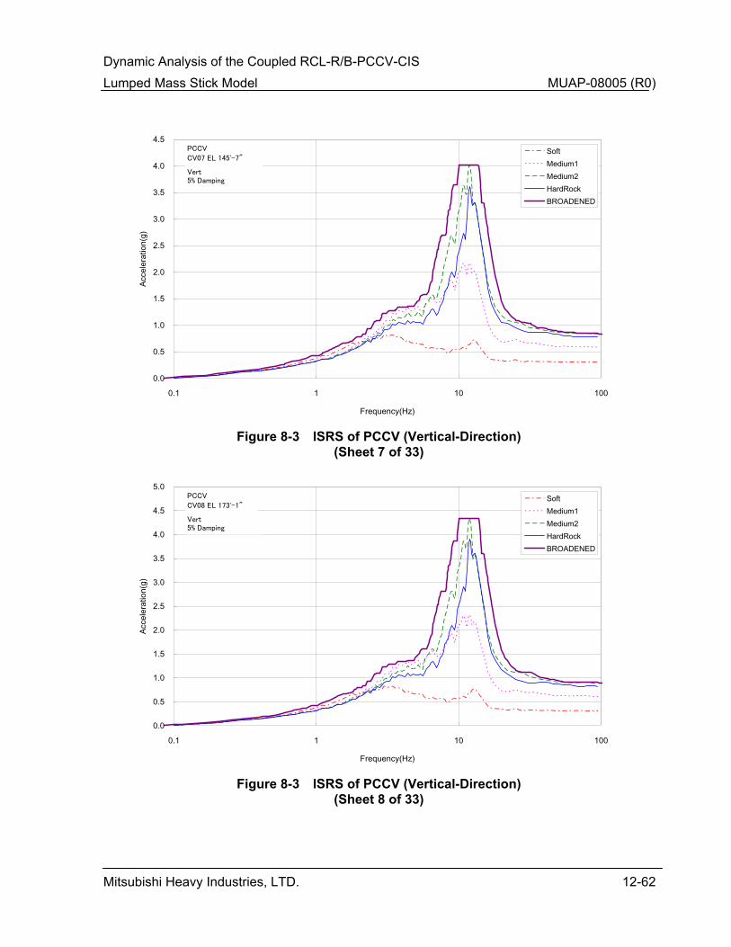
Dynamic Analysis of the Coupled RCL-R/B-PCCV-CIS Lumped Mass Stick Model MUAP-08005 (R0)
Mitsubishi Heavy Industries, LTD. 12-62
0.0
0.5
1.0
1.5
2.0
2.5
3.0
3.5
4.0
4.5
0.1 1 10 100
Frequency(Hz)
Acce
lera
tion(
g)SoftMedium1Medium2HardRockBROADENED
CV07 EL 145'-7"
PCCV
Vert5% Damping
Figure 8-3 ISRS of PCCV (Vertical-Direction)
(Sheet 7 of 33)
0.0
0.5
1.0
1.5
2.0
2.5
3.0
3.5
4.0
4.5
5.0
0.1 1 10 100
Frequency(Hz)
Acce
lera
tion(
g)
SoftMedium1Medium2HardRockBROADENED
CV08 EL 173'-1"
PCCV
Vert5% Damping
Figure 8-3 ISRS of PCCV (Vertical-Direction)
(Sheet 8 of 33)
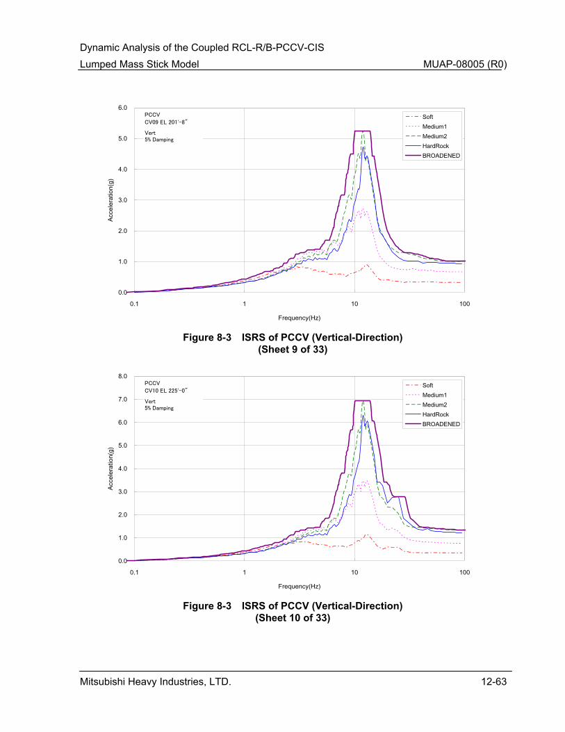
Dynamic Analysis of the Coupled RCL-R/B-PCCV-CIS Lumped Mass Stick Model MUAP-08005 (R0)
Mitsubishi Heavy Industries, LTD. 12-63
0.0
1.0
2.0
3.0
4.0
5.0
6.0
0.1 1 10 100
Frequency(Hz)
Acce
lera
tion(
g)SoftMedium1Medium2HardRockBROADENED
CV09 EL 201'-8"
PCCV
Vert5% Damping
Figure 8-3 ISRS of PCCV (Vertical-Direction)
(Sheet 9 of 33)
0.0
1.0
2.0
3.0
4.0
5.0
6.0
7.0
8.0
0.1 1 10 100
Frequency(Hz)
Acce
lera
tion(
g)
SoftMedium1Medium2HardRockBROADENED
CV10 EL 225'-0"
PCCV
Vert5% Damping
Figure 8-3 ISRS of PCCV (Vertical-Direction)
(Sheet 10 of 33)

Dynamic Analysis of the Coupled RCL-R/B-PCCV-CIS Lumped Mass Stick Model MUAP-08005 (R0)
Mitsubishi Heavy Industries, LTD. 12-64
0.0
1.0
2.0
3.0
4.0
5.0
6.0
7.0
8.0
9.0
0.1 1 10 100
Frequency(Hz)
Acce
lera
tion(
g)SoftMedium1Medium2HardRockBROADENED
CV11 EL 230'-2"
PCCV
Vert5% Damping
Figure 8-3 ISRS of PCCV (Vertical-Direction)
(Sheet 11 of 33)
0.0
0.2
0.4
0.6
0.8
1.0
1.2
1.4
0.1 1 10 100
Frequency(Hz)
Acce
lera
tion(
g)
SoftMedium1Medium2HardRockBROADENED
IC01 EL 16'-0"
CIS
Vert5% Damping
Figure 8-3 ISRS of CIS (Vertical-Direction)
(Sheet 12 of 33)

Dynamic Analysis of the Coupled RCL-R/B-PCCV-CIS Lumped Mass Stick Model MUAP-08005 (R0)
Mitsubishi Heavy Industries, LTD. 12-65
0.0
0.2
0.4
0.6
0.8
1.0
1.2
1.4
0.1 1 10 100
Frequency(Hz)
Acce
lera
tion(
g)SoftMedium1Medium2HardRockBROADENED
IC02 EL 25'-3"
CIS
Vert5% Damping
Figure 8-3 ISRS of CIS (Vertical-Direction)
(Sheet 13 of 33)
0.0
0.2
0.4
0.6
0.8
1.0
1.2
1.4
0.1 1 10 100
Frequency(Hz)
Acce
lera
tion(
g)
SoftMedium1Medium2HardRockBROADENED
IC03 EL 35'-7.25"
CIS
Vert5% Damping
Figure 8-3 ISRS of CIS (Vertical-Direction)
(Sheet 14 of 33)

Dynamic Analysis of the Coupled RCL-R/B-PCCV-CIS Lumped Mass Stick Model MUAP-08005 (R0)
Mitsubishi Heavy Industries, LTD. 12-66
0.0
0.2
0.4
0.6
0.8
1.0
1.2
1.4
1.6
0.1 1 10 100
Frequency(Hz)
Acce
lera
tion(
g)SoftMedium1Medium2HardRockBROADENED
IC14 EL 45'-8"
CIS
Vert5% Damping
Figure 8-3 ISRS of CIS (Vertical-Direction)
(Sheet 15 of 33)
0.0
0.2
0.4
0.6
0.8
1.0
1.2
1.4
1.6
0.1 1 10 100
Frequency(Hz)
Acce
lera
tion(
g)
SoftMedium1Medium2HardRockBROADENED
IC04 EL 50'-2"
CIS
Vert5% Damping
Figure 8-3 ISRS of CIS (Vertical-Direction)
(Sheet 16 of 33)
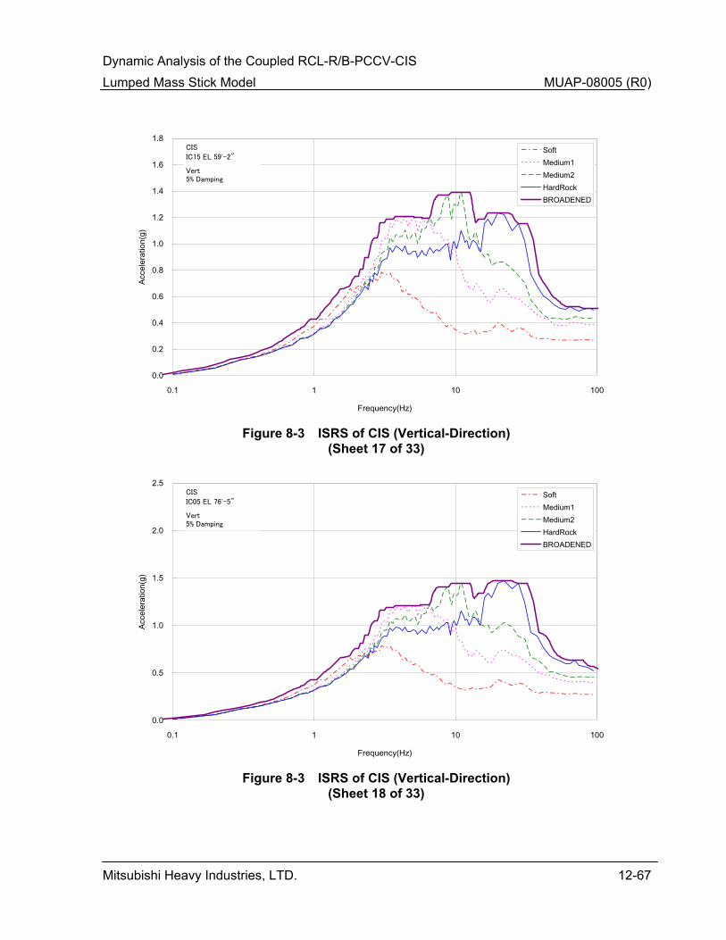
Dynamic Analysis of the Coupled RCL-R/B-PCCV-CIS Lumped Mass Stick Model MUAP-08005 (R0)
Mitsubishi Heavy Industries, LTD. 12-67
0.0
0.2
0.4
0.6
0.8
1.0
1.2
1.4
1.6
1.8
0.1 1 10 100
Frequency(Hz)
Acce
lera
tion(
g)SoftMedium1Medium2HardRockBROADENED
IC15 EL 59'-2"
CIS
Vert5% Damping
Figure 8-3 ISRS of CIS (Vertical-Direction)
(Sheet 17 of 33)
0.0
0.5
1.0
1.5
2.0
2.5
0.1 1 10 100
Frequency(Hz)
Acce
lera
tion(
g)
SoftMedium1Medium2HardRockBROADENED
IC05 EL 76'-5"
CIS
Vert5% Damping
Figure 8-3 ISRS of CIS (Vertical-Direction)
(Sheet 18 of 33)

Dynamic Analysis of the Coupled RCL-R/B-PCCV-CIS Lumped Mass Stick Model MUAP-08005 (R0)
Mitsubishi Heavy Industries, LTD. 12-68
0.0
0.5
1.0
1.5
2.0
2.5
3.0
0.1 1 10 100
Frequency(Hz)
Acce
lera
tion(
g)SoftMedium1Medium2HardRockBROADENED
IC61 EL 96'-7"
CIS
Vert5% Damping
Figure 8-3 ISRS of CIS (Vertical-Direction)
(Sheet 19 of 33)
0.0
0.5
1.0
1.5
2.0
2.5
3.0
0.1 1 10 100
Frequency(Hz)
Acce
lera
tion(
g)
SoftMedium1Medium2HardRockBROADENED
IC62 EL 96'-7"
CIS
Vert5% Damping
Figure 8-3 ISRS of CIS (Vertical-Direction)
(Sheet 20 of 33)
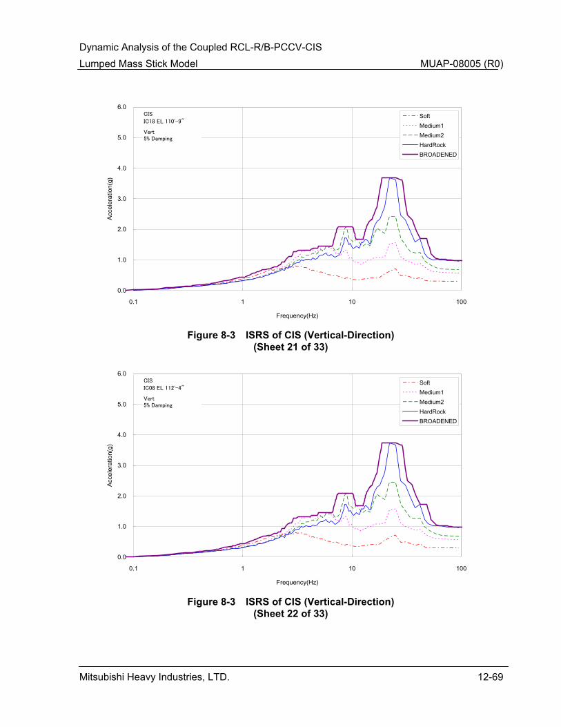
Dynamic Analysis of the Coupled RCL-R/B-PCCV-CIS Lumped Mass Stick Model MUAP-08005 (R0)
Mitsubishi Heavy Industries, LTD. 12-69
0.0
1.0
2.0
3.0
4.0
5.0
6.0
0.1 1 10 100
Frequency(Hz)
Acce
lera
tion(
g)SoftMedium1Medium2HardRockBROADENED
IC18 EL 110'-9"
CIS
Vert5% Damping
Figure 8-3 ISRS of CIS (Vertical-Direction)
(Sheet 21 of 33)
0.0
1.0
2.0
3.0
4.0
5.0
6.0
0.1 1 10 100
Frequency(Hz)
Acce
lera
tion(
g)
SoftMedium1Medium2HardRockBROADENED
IC08 EL 112'-4"
CIS
Vert5% Damping
Figure 8-3 ISRS of CIS (Vertical-Direction)
(Sheet 22 of 33)

Dynamic Analysis of the Coupled RCL-R/B-PCCV-CIS Lumped Mass Stick Model MUAP-08005 (R0)
Mitsubishi Heavy Industries, LTD. 12-70
0.0
1.0
2.0
3.0
4.0
5.0
6.0
0.1 1 10 100
Frequency(Hz)
Acce
lera
tion(
g)SoftMedium1Medium2HardRockBROADENED
IC09 EL 139'-6"
CIS
Vert5% Damping
Figure 8-3 ISRS of CIS (Vertical-Direction)
(Sheet 23 of 33)
0.0
0.2
0.4
0.6
0.8
1.0
1.2
1.4
1.6
0.1 1 10 100
Frequency(Hz)
Acce
lera
tion(
g)
SoftMedium1Medium2HardRockBROADENED
RE01 EL 25'-3"
R/B
Vert5% Damping
Figure 8-3 ISRS of R/B (Vertical-Direction)
(Sheet 24 of 33)
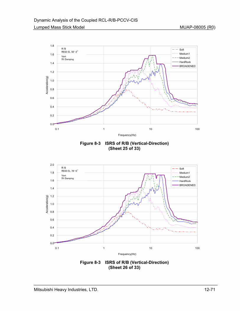
Dynamic Analysis of the Coupled RCL-R/B-PCCV-CIS Lumped Mass Stick Model MUAP-08005 (R0)
Mitsubishi Heavy Industries, LTD. 12-71
0.0
0.2
0.4
0.6
0.8
1.0
1.2
1.4
1.6
1.8
0.1 1 10 100
Frequency(Hz)
Acce
lera
tion(
g)SoftMedium1Medium2HardRockBROADENED
RE02 EL 50'-2"
R/B
Vert5% Damping
Figure 8-3 ISRS of R/B (Vertical-Direction)
(Sheet 25 of 33)
0.0
0.2
0.4
0.6
0.8
1.0
1.2
1.4
1.6
1.8
2.0
0.1 1 10 100
Frequency(Hz)
Acce
lera
tion(
g)
SoftMedium1Medium2HardRockBROADENED
RE03 EL 76'-5"
R/B
Vert5% Damping
Figure 8-3 ISRS of R/B (Vertical-Direction)
(Sheet 26 of 33)

Dynamic Analysis of the Coupled RCL-R/B-PCCV-CIS Lumped Mass Stick Model MUAP-08005 (R0)
Mitsubishi Heavy Industries, LTD. 12-72
0.0
0.5
1.0
1.5
2.0
2.5
3.0
3.5
4.0
4.5
0.1 1 10 100
Frequency(Hz)
Acce
lera
tion(
g)SoftMedium1Medium2HardRockBROADENED
RE04 EL 101'-0"
R/B
Vert5% Damping
Figure 8-3 ISRS of R/B (Vertical-Direction)
(Sheet 27 of 33)
0.0
0.5
1.0
1.5
2.0
2.5
3.0
3.5
4.0
4.5
0.1 1 10 100
Frequency(Hz)
Acce
lera
tion(
g)
SoftMedium1Medium2HardRockBROADENED
RE05 EL 115'-6"
R/B
Vert5% Damping
Figure 8-3 ISRS of R/B (Vertical-Direction)
(Sheet 28 of 33)
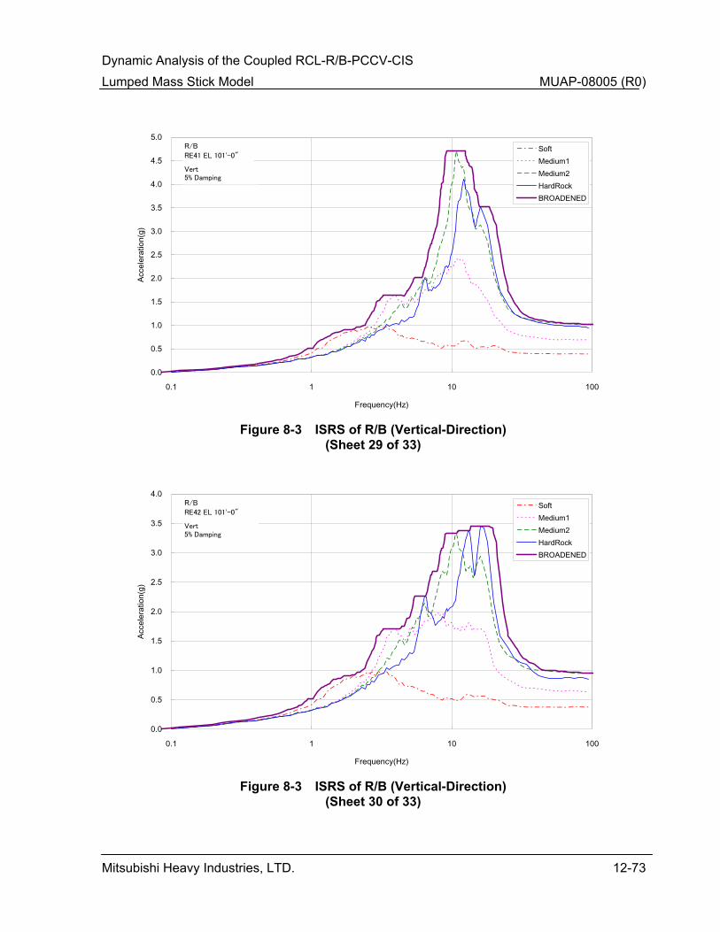
Dynamic Analysis of the Coupled RCL-R/B-PCCV-CIS Lumped Mass Stick Model MUAP-08005 (R0)
Mitsubishi Heavy Industries, LTD. 12-73
0.0
0.5
1.0
1.5
2.0
2.5
3.0
3.5
4.0
4.5
5.0
0.1 1 10 100
Frequency(Hz)
Acce
lera
tion(
g)SoftMedium1Medium2HardRockBROADENED
RE41 EL 101'-0"
R/B
Vert5% Damping
Figure 8-3 ISRS of R/B (Vertical-Direction)
(Sheet 29 of 33)
0.0
0.5
1.0
1.5
2.0
2.5
3.0
3.5
4.0
0.1 1 10 100
Frequency(Hz)
Acce
lera
tion(
g)
SoftMedium1Medium2HardRockBROADENED
RE42 EL 101'-0"
R/B
Vert5% Damping
Figure 8-3 ISRS of R/B (Vertical-Direction)
(Sheet 30 of 33)
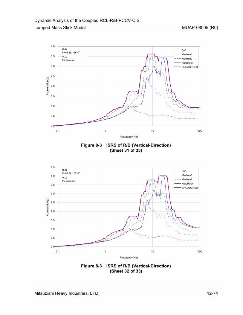
Dynamic Analysis of the Coupled RCL-R/B-PCCV-CIS Lumped Mass Stick Model MUAP-08005 (R0)
Mitsubishi Heavy Industries, LTD. 12-74
0.0
0.5
1.0
1.5
2.0
2.5
3.0
3.5
4.0
0.1 1 10 100
Frequency(Hz)
Acce
lera
tion(
g)SoftMedium1Medium2HardRockBROADENED
FH06 EL 101'-0"
R/B
Vert5% Damping
Figure 8-3 ISRS of R/B (Vertical-Direction)
(Sheet 31 of 33)
0.0
0.5
1.0
1.5
2.0
2.5
3.0
3.5
4.0
4.5
0.1 1 10 100
Frequency(Hz)
Acce
lera
tion(
g)
SoftMedium1Medium2HardRockBROADENED
FH07 EL 125'-8"
R/B
Vert5% Damping
Figure 8-3 ISRS of R/B (Vertical-Direction)
(Sheet 32 of 33)

Dynamic Analysis of the Coupled RCL-R/B-PCCV-CIS Lumped Mass Stick Model MUAP-08005 (R0)
Mitsubishi Heavy Industries, LTD. 12-75
0.0
0.5
1.0
1.5
2.0
2.5
3.0
3.5
4.0
4.5
5.0
0.1 1 10 100
Frequency(Hz)
Acce
lera
tion(
g)SoftMedium1Medium2HardRockBROADENED
FH08 EL 154'-6"
R/B
Vert5% Damping
Figure 8-3 ISRS of R/B (Vertical-Direction)
(Sheet 33 of 33)