Embed Size (px)
Citation preview
MiniMux® ii TeMperaTure & process scanner
Precision Digital corPoration www.predig.com
scan MosT siGnaLs/sensorsThe Minimux II is a microprocessor-based eight channel analog input scanner/multipexer and annunciator that provides low-cost automatic switching for multi-point display and alarm systems. Each Minimux II can automatically switch up to eight inputs to another device such as a digital panel meter, controller, or PLC. Signal switching is done via reed relays making the Minimux II ideal for switching thermocouples, RTDs, control loops, and AC & DC signals.
uses for MiniMux ii
automatic switchingIn its most basic form, the PD138 is the electrical equivalent of a double-pole, eight position automatic switch. Whatever input is brought into the PD138 is dwelled on for a certain amount of time while being channeled/switched out to another device. For example, a typical application may involve channeling/switching eight type J thermocouples into a single digital panel meter.
Temperature scanningOne of the most popular uses for the PD138 is temperature monitoring, especially the monitoring of bearing and stator winding temperatures. Any of the many different style thermocouples, RTDs, or thermistors can be used with the PD138 - right out of the box.
automatic or Manual scanThe PD138 automatically scans through each active channel, dwells on that channel for an independently programmed dwell time, while at the same time switching the signal to an external device. The scanning can be stopped, or scanned manually via the front panel stop/go pushbutton.
alarm annunciatorOne of the key features of the PD138 is its ability to indicate and process alarms that are generated by an external device. Each channel of the Minimux II has an independent ‘Alarm-in’ terminal that allows an external device to trigger an alarm on the Minimux II. The external device may be the relays on a digital panel meter, such as the PD765, or the digital output from a PLC.
first-out (sequence f2a)The PD138 can be configured to recognize first-out alarms. On the PD138, these are one or more alarms that occur during the first complete scan where an alarm is present on one or more channels.
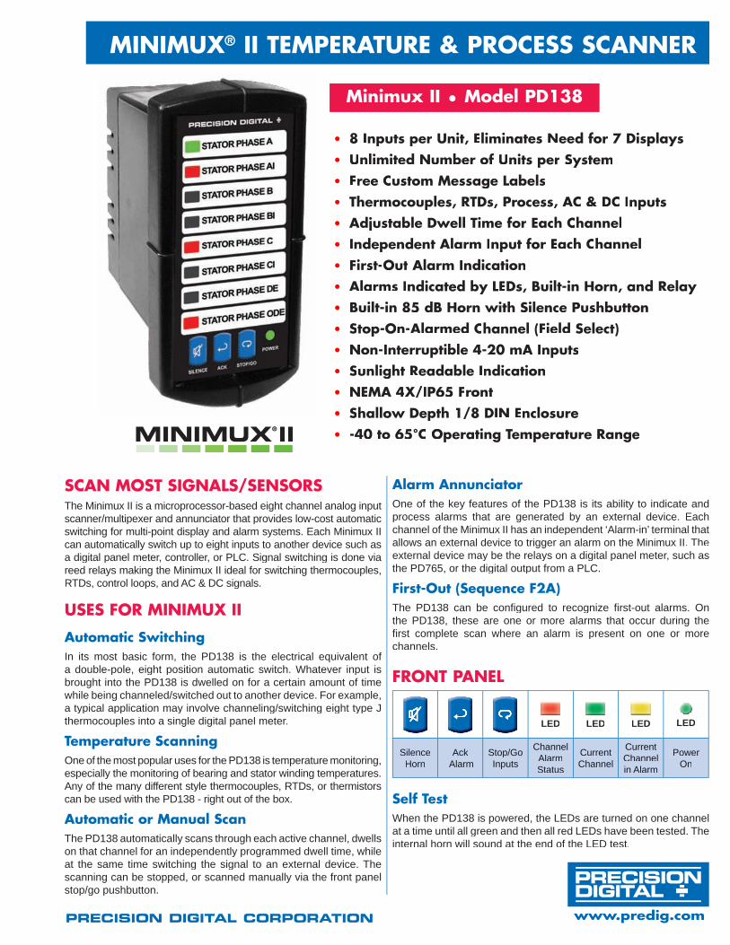
fronT paneL
LED LED LED LED
Silence Horn
Ack Alarm
Stop/Go Inputs
Channel AlarmStatus
Current Channel
Current Channel in Alarm
Power On
Minimux ii • Model pD138
8 inputs per unit, eliminates need for 7 Displays•
unlimited number of units per system•
free custom Message Labels•
Thermocouples, rTDs, rTDs, r process, ac & Dc inputs•
adjustable Dwell Time for each channel•
independent alarm input for each channel•
first-out alarm indication•
alarms indicated by LeDs, Built-in Horn, and relay•
Built-in 85 dB Horn with silence pushbutton•
stop-on-alarmed channel (field select)•
non-interruptible 4-20 ma inputs•
sunlight readable indication•
neMa 4a 4a x/ip65 front•
shallow Depth 1/8 Din enclosure•
-40 to 65°c operating Temperature range•
self TestWhen the PD138 is powered, the LEDs are turned on one channel at a time until all green and then all red LEDs have been tested. The internal horn will sound at the end of the LED test.
MoDeL pD138 MiniMux® ii TeMperaTure & process scanner
2
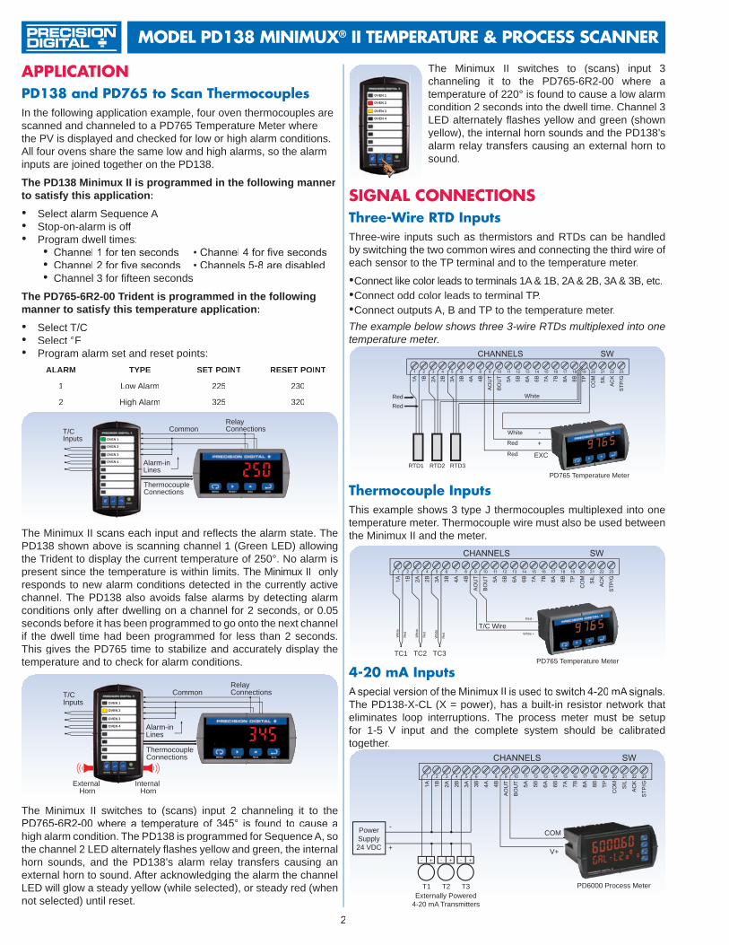
appLicaTionpD138 and pD765 to scan ThermocouplesIn the following application example, four oven thermocouples are scanned and channeled to a PD765 Temperature Meter where the PV is displayed and checked for low or high alarm conditions. All four ovens share the same low and high alarms, so the alarm inputs are joined together on the PD138.
The PD138 Minimux II is programmed in the following manner to satisfy this application:
Select alarm Sequence A•Stop-on-alarm is off•Program dwell times:• Channel 1 for ten seconds • Channel 4 for five seconds• Channel 2 for five seconds • Channels 5-8 are disabled•Channel 3 for fifteen seconds•
The PD765-6R2-00 Trident is programmed in the following manner to satisfy this temperature application:
Select T/C•Select• °FProgram alarm set and reset points:•
ALARM TYPE SET POINT RESET POINT
1 Low Alarm 225 230
2 High Alarm 325 320
Common
Alarm-inLines
RelayConnectionsT/C
Inputs OVEN 1
OVEN 2
OVEN 3
OVEN 4
ThermocoupleConnections
1
The Minimux II scans each input and reflects the alarm state. The PD138 shown above is scanning channel 1 (Green LED) allowing the Trident to display the current temperature of 250°. No alarm is present since the temperature is within limits. The Minimux II only responds to new alarm conditions detected in the currently active channel. The PD138 also avoids false alarms by detecting alarm conditions only after dwelling on a channel for 2 seconds, or 0.05 seconds before it has been programmed to go onto the next channel if the dwell time had been programmed for less than 2 seconds. This gives the PD765 time to stabilize and accurately display the temperature and to check for alarm conditions.
The Minimux II switches to (scans) input 2 channeling it to the PD765-6R2-00 where a temperature of 345° is found to cause ahigh alarm condition. The PD138 is programmed for Sequence A, so the channel 2 LED alternately flashes yellow and green, the internal horn sounds, and the PD138’s alarm relay transfers causing an external horn to sound. After acknowledging the alarm the channel LED will glow a steady yellow (while selected), or steady red (when not selected) until reset.
CommonRelayConnectionsT/C
Inputs OVEN 1
OVEN 2
OVEN 3
OVEN 4
ThermocoupleConnections
InternalHorn
ExternalHorn
1 2
Alarm-inLines
OVEN 1
OVEN 2
OVEN 3
OVEN 4
The Minimux II switches to (scans) input 3 channeling it to the PD765-6R2-00 where a temperature of 220° is found to cause a low alarm condition 2 seconds into the dwell time. Channel 3 LED alternately flashes yellow and green (shown yellow), the internal horn sounds and the PD138’s alarm relay transfers causing an external horn to sound.
PD765 Temperature MeterRTD1 RTD2 RTD3
EXC
+-White
Red
Red
RedRed
White
siGnaL connecTionsThree-Wire rTD inputsThree-wire inputs such as thermistors and RTDs can be handled by switching the two common wires and connecting the third wire of each sensor to the TP terminal and to the temperature meter.
Connect like color leads to terminals 1A & 1B, 2A & 2B, 3A & 3B, etc.•Connect odd color leads to terminal TP.•Connect outputs A, B and TP to the temperature meter.•
The example below shows three 3-wire RTDs multiplexed into one temperature meter.
Thermocouple inputsThis example shows 3 type J thermocouples multiplexed into one temperature meter. Thermocouple wire must also be used between the Minimux II and the meter.
TC1 TC2 TC3
T/C WireWhite +
Red -
Whi
te
Red
Whi
te
Red
Whi
te
Red
PD765 Temperature Meter
PD6000 Process MeterT1 T2 T3
V+
COMPowerSupply24 VDC
- + - + - +
Externally Powered4-20 mA Transmitters
-
+
4-20 ma inputsAspecial version of the Minimux II is used to switch 4-20 mAsignals.The PD138-X-CL (X = power), has a built-in resistor network that eliminates loop interruptions. The process meter must be setup for 1-5 V input and the complete system should be calibrated together.
MoDeL pD138 MiniMux® ii TeMperaTure & process scanner
3
Master
21 22 23SIL ACK STP/G
Optional external N.O. pushbuttons used forremote SILENCE, ACK, & STOP/GO functions
20COM
Follower 2
21 22 23SIL ACK STP/G
20COM
Follower 1
21 22 23SIL ACK STP/G
20COM
PD6000 Process MeterT1 T2 T3
P+
mA+
- + - + - +
4-20 mA TransmittersPowered by the PD6000
P-COM
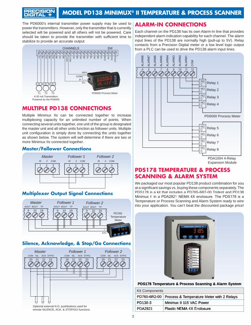
The PD6000’s internal transmitter power supply may be used to power the transmitters. However, only the transmitter that is currently selected will be powered and all others will not be powered. Care should be taken to provide the transmitter with sufficient time to stabilize to provide an accurate output.
pDs178 TeMperaTure & process scanninG & aLarM sYsTeMWe packaged our most popular PD138 product combination for you at a significant savings vs. buying these components separately. The PDS178 is a kit that includes a PD765-6R2-00 Trident and PD138 Minimux II in a PDA2821 NEMA 4X enclosure. The PDS178 is aTemperature or Process Scanning and Alarm System ready to wire into your application. You can’t beat the discounted package price!
PDS178 Temperature & Process Scanning & Alarm System
MuLTipLe pD138 connecTionsMultiple Minimux IIs can be connected together to increase multiplexing capacity for an unlimited number of points. When connecting several units together, one unit of the group is designated the master unit and all other units function as follower units. Multiple unit configuration is simply done by connecting the units together as shown below. The system will self-determine if there are two or more Minimux IIs connected together.
Master/follower connections
Master Follower 1 Follower 2
Multiplexer output signal connections
Master
9 10 19AOUT BOUT TP
Follower 2
9 10 19AOUT BOUT TP
Follower 1
9 10 19AOUT BOUT TP
-+
EXC
PD765Temperature
Meter
silence, acknowledge, & stop/Go connections
aLarM-in connecTionsEach channel on the PD138 has its own Alarm-In line that provides independent alarm indication capability for each channel. The alarm input lines of the PD138 are normally high (pull-up to 5V). Relay contacts from a Precision Digital meter or a low level logic output from a PLC can be used to drive the PD138 alarm input lines.
NOCNOCNOCNOC
Relay 1
Relay 2
Relay 3
Relay 4
PD6000 Process Meter
NOCNOCNOCNOC
Relay 5
Relay 6
Relay 7
Relay 8
PDA1004 4-Relay Expansion Module
Kit ComponentsPD765-6R2-00 Process & Temperature Meter with 2 RelaysPD138-3 Minimux II 115 VAC PowerPDA2821 Plastic NEMA 4X Enclosure

www.predig.comPrecision Digital corPoration89 October Hill Rd • Holliston MA 01746 USA • Tel (800) 343-1001 • Fax (508) 655-8990
LDS138_A02/09
MoDeL pD138 MiniMux® ii TeMperaTure & process scanner
specificaTionsExcept where noted all specifications apply to operation at +25°C.
Generalnumber of Channels: 8 double-pole channels per unitnumber of Channels Per System: UnlimitedSignals Switching: DPST reed relaysContact Resistance:0.2ΩmaximumMaximum Input Voltage: 200 VAC/DC (switched or common mode)Maximum Current Switched: 0.5 AMaximum Power Switched: 10 WDwell Time: Each channel adjustable from 0.6 to 30 secondsnon-Volatile Memory: All programming values are stored in non-volatile memory for ten years if power is lostScan Method: Internally or manually controlledChannel Indication: Green LED on front panelDisabling Channels: Any channel may be disabledScan Stop: The scan may be stopped by pressing and holding the STOP/GO button for more than 0.5 seconds. The scan may be resumed by pressing and releasing the STOP/GO button quickly (less than 0.5 seconds)Alarm Input: Independent alarm input for each channel. Input Impedance; 25 Kohm, typical pull-up to 5 VAlarm Sequence: Sequence A or Sequence F2A (first out)Alarm outputs: Alarm condition indicated by:
Front panel red LED for each channel.1. Relay, 1 SPDT (form C); rated 2 Amp @ 30 VDC or 2 Amp 2.
@250VACresistiveload;1/14HP@125/250VACfor inductive loads. For failsafe operation, the relay is energized in the non-alarm state. In the case of a power failure, the relay will go to the alarm state, (NC contact is connected to common).
Built-in Horn, 85 dB.3. Stop-on-alarmed-channel (user select)4.
Alarm Acknowledge: Front panel ACK and rear connector terminalsExternal Switch Functions: The functions of the front panel buttons are available at screw terminals at the rear of the instrumentMessage Labels:Free,customprinted,2linespermessageat14characters per line. Factory or field printable. See manual for details.Connections: Removable screw terminal connectors provided:Power + Relay: 22 to 12 AWG; Alarm Input, Analog Signal, External Switches, I/O: 30 to 16 AWGoperating Temperature:-40°Cto65°CStorage Temperature:-40°Cto85°CRelative Humidity: 0 to 95% non-condensingPower options:115VAC,±10%,50/60Hz,4VA;230VAC,±10%,50/60Hz,4VA;12-24VDC(9-18VAC,50/60Hz)2WLed Test: All LEDs are tested on power-upEnclosure:1/8DIN,highimpactplastic,UL94V-0Front Panel:NEMA4X,panelgasketprovidedWeight: 9.9 oz (280 g)Warranty: 3 years parts and labor
DisclaimerThe information contained in this document is subject to change without notice. Precision Digital Corporation makes no representations or warranties with respect to the contents hereof, and specificallydisclaimsanyimpliedwarrantiesofmerchantabilityorfitnessforaparticularpurpose.
©2009 Precision Digital Corporation. All rights reserved.
MounTinG DiMensions
connecTions
3.61"(92mm)
2.50"(64mm)
4.68"(119mm)
1.76"(45mm)
0.59"(15mm)
3.0"(76mm)
2.45"(62mm)
3.1"(79mm)
Top View
Side View
orDerinG inforMaTionMinimux II • Model PD138
Model With Loop Resistor Description Power
PD138-2 PD138-2-CL 8 Chan. Temp & Process Scanner 24VDC
PD138-3 PD138-3-CL 8 Chan. Temp & Process Scanner 115 VAC
PD138-4 PD138-4-CL 8 Chan. Temp & Process Scanner 230 VAC
AccessoriesModel Units Description Mounting
PDA25XX-V 1-10* PlasticNEMA4XEnclosure Through Door
PDA26XX-V 1-6* StainlessSteelNEMA4X Through Door
PDA27XX-V 1-6* SteelNEMA4Enclosure Through Door
PDA2801 1 Low-CostPlasticNEMA4X Through Cover
PDA2821 2 Low-CostPlasticNEMA4X (1 vertical + 1 horizontal) Through Cover
Note: XX = the last two digits of the model number*Gotowww.predig.comtofindindividualmodelnumbers.
SystemsModel Description Kit Components
PDS178 Temperature Scanning & Alarming System
PD765-6R2-00PD138-3PDA2821
Process & Temp MeterMinimux IIPlasticNEMA4XEncl.