Embed Size (px)
Citation preview

Part No. 987016 ProMinent Dosiertechnik GmbH · 69123 Heidelberg · Germany BA BEZ 022 07/04 GB
Operating Instructions ManualProMinent® Chlorine Dioxide SystemsBello Zon® Type CDVbPart 2
For safe and correct operation of the Bello Zon® system you need Parts 1 and 2of the Operating Instructions Manual.
The two are valid only when read in conjunction with one another.
Please read through operating instructions manual carefully before use. Do not discard.The guarantee is void if the equipment is installed incorrectly.
Please enter the identcode of the device here
___ ___ ___ ___ ___ ___ ___ ___ ___ ___CDVb
CDVb 15-120
ProM
inen
t®
BA_BEZ_022_07_08_GB.p65 09.07.2008, 11:25 Uhr1

Page 2 ProMinent®
Publishing Details
Publishing details:Operating Instructions ManualBello Zon® Type CDVb, Part 2©ProMinent Dosiertechnik GmbH, 2003
ProMinent Dosiertechnik GmbHIm Schuhmachergewann 5-1169123 Heidelberg · GermanyTel. :+49 6221 842-0Fax:+49 6221 842-419
[email protected]. prominent. de
Subject to revisionPrinted in Germany.
Please fold out this page!
BA_BEZ_022_07_08_GB.p65 09.07.2008, 11:25 Uhr2

Page 3ProMinent®
Controller
LEDs
L 1 Green operating indicatorL 2 Red warning light (steady light)
Fault indicator (flashes)
L 3 Yellow Yellow Actuation, chloride metering pumpRed feed monitor, chlorite pump : fault
L 4 Green feed monitor, chloride pump : OK
L 5 No functionL 6 No function
L 7 Yellow Actuation, metering pump, acidRed feed monitor, pump, acid: fault
L 8 Green feed monitor, pump, acid: OK
L 9 Yellow Actuation, bypass pumpRed bypass monitor: fault
L 10 Green bypass monitor: OK
Säure Wasser ChloritChloriteWaterAcidBypass
Bypass
R
START
STOP
L 10 L 9 L 8 L 7 L 6 L 5 L 4 L 3
L 2
L 1
Controller
Fig. 1
BA_BEZ_022_07_08_GB.p65 09.07.2008, 11:25 Uhr3

Page 4 ProMinent®
START /STOP buttonTo start/stop metering function.
QUIT buttonTo acknowledge alarm or error warnings (if L 2 flashes).
ENTER buttonFor (horizontal) movement within the operating menu and to save a displayed value or status.
LC display
CHANGE buttonTo change between the setting menus, change between the permanent display and the infodisplays and to change between the digits of the active code.
SUCTION buttonTo gauge capacity in litres (in the menu item “Gauge capacity in litres of pump”): the meteringpumps run at the maximum stroke rate until the set capacity gauging volume has been reached.To start up (in the menu item “Start up”): the metering pumps run for the pre-set run-in period atthe maximum stroke rate.Suction: the metering pumps carry out 20 strokes at the maximum stroke rate.If the “Acid “ feed monitor produces 8 error pulses at this point the chlorite pump stops (forsafety).
SUCTION buttonTo extract gases from the reactor cabinet.
DOWN buttonTo reduce a displayed numerical value and to change a variable (flashes).
BACK keyTo exit the parameter menus or the configuration menus without saving the displayed numericalvalue or variable.
UP buttonTo increase a displayed numerical value and to change a variable (flashes).
Controller
1
2
3
4
5
6
7
8
9
10
Fig. 2
Säure Wasser ChloritChloriteWaterAcidBypass
Bypass
R
START
STOP
1
2
4 35
6
7
1098
Buttons and LC display
BA_BEZ_022_07_08_GB.p65 09.07.2008, 11:25 Uhr4

Page 5ProMinent®
Page
Identcode 6 Operating code 7 General user instructions 81 About this equipment 92 Safety 103 Equipment overview 144 Function description 155 Settings 17
5.1 Operating mode “internal actuation” 185.2 Operating mode ”Flow-dependant actuation” 195.3 Operating mode ”Control variable-dependant actuation” 20
6 Commissioning 216.1 Installation - final steps 216.2 Configuring controller 21
6.2.1 Operating mode ”Internal actuation” 216.2.2 Operating mode ”Flow-dependant actuation” 226.2.3 Operating mode ”Control variable-dependant actuation” 25
6.3 Starting up the system 266.4 Checking for tightness 276.5 Discharging metering pumps 276.6 Setting feed monitors 286.7 Checking safety devices 296.8 Installing component containers 296.9 Checking chlorine dioxide generation 296.10 Setting pause metering 29
7 Operating 307.1 Replacing component containers 307.2 Bleeding metering pumps 317.3 Discharging metering pumps 317.4 Checking chlorine dioxide generation 327.5 Feed monitor settings 33
8 What happens in the event of incorrect use 349 Maintenance 35
9.1.1 Servicing by service technicians only 359.1.2 Regular checks, possible without service 36
10 Repair 4111 Troubleshooting 4112 Decommissioning 44
12.1 For a short period 4412.2 For a longer period 4412.3 Preparing for frost-proof storage 45
13 Disposal 4614 Technical specifications 4615 Spare parts 4816 Accessories 4917 Options 50
Appendix
Leaflet “Safety data sheet, Chlorine dioxide: characteristics of chlorine dioxide and notes forhandling with aqueous solutions ”
Leaflet “Bello Zon® acid-03, safety data sheet in accordance with guideline 91/155/EWG ”
Leaflet “Bello Zon® chlorite-03, safety data sheet in accordance with guideline 91/155/EWG ”
EU conformity declaration
Literature list
Table of contents
BA_BEZ_022_07_08_GB.p65 09.07.2008, 11:25 Uhr5

Page 6 ProMinent®
Identcode
The Bello Zon® system is supplied with a factory-set Identcode. The Identcode is made up of the systemcomposition as specified in the order, e.g. flow-dependent or measured value-dependent metering, as specified.
Identcode
CDVb — — — — — — — — — —
CDVb chlorine dioxide system type CDVbSystem type: ClO2 feed rate
0 A CDVb 15 = 15 g/h1 A CDVb 35 = 46 g/h2 A CDVb 60 = 66 g/h3 A CDVb 120 = 130 g/h4 A CDVb 220 = 225 g/h6 A CDVb 600 = 600 g/h8 A CDVb 2000 = 2000 g/h
Operating voltage:0 230 V, 50/60 Hz1 115 V, 50*/60 Hz4 24 V (only CDV 15-120)
* CDVb 600-2000 not available in 115 V, 50 Hz version
Chemical suction lance:0 none1 suction lance for 30 l tanks2 suction lance for 200 l tanks3 suction lance for 500 l tanks4 suction lance for 1000 l tanks (CDV 600 and CDV 2000 only)5 flexible suction assembly up to 5 m with two stage float switch (CDV 35-120)9 suction lance for 30 l tanks with 2 x 40 l drip trays without leak sensor
Bypass version:0 bypass without preliminary mixer and without bypass monitor1 bypass with preliminary mixer and without bypass monitor2 bypass without preliminary mixer and with bypass monitor (float and orifice flow meter)3 bypass with preliminary mixer and with bypass monitor (float and orifice flow meter)4 PVC-C bypass without preliminary mixer and without bypass monitor5 PVC-C bypass without preliminary mixer and with bypass monitor (float and orifice flow meter)9 bypass with preliminary mixer and with bypass monitor and with stainless steel bypass pump
Control variable input:(for the connection of a controller for measured value-dependent metering)
0 none1 contact, pulse range 0-4 Hz2 analogue (0/4-20 mA) or contact (commutator)
Flow input:(for connection of a water meter)
0 none1 contact, pulse range 0-4 Hz2 frequency, max. 10 kHz and contact (commutator)3 analogue (0/4-20 mA) or contact (commutator)
Language presetting:D GermanE EnglishF FrenchI ItalianS SpanishP PolishC CzechM HungarianB PortugueseR RomanianN Dutch
Analogue output:0 none (standard)1 analogue (0/4-20 mA) for computer or remote display
Remote control input:0 none1 contact (pause function)2 analogue (0/4-20 mA)3 contact and analogue (0/4-20 mA)
Temperature monitor:0 with extractor unit and without temperature monitor1 with extractor unit and with temperature monitor2 without extractor unit and without temperature monitor
BA_BEZ_022_07_08_GB.p65 09.07.2008, 11:25 Uhr6

Page 7ProMinent®
Operating code
Operating code
If changing the intended use of the equipment it is possible - to a limited extent - to change the controller pre-settings(depending on the existing hardware). The operating code is used for this purpose.
Example: system version Identcode CDKb xAxxx11Dxxx has both contact signal actuation variants - you select the one you want using the operating codeA “0” in the corresponding identity code position indicates that this version cannot be activated by the operating code.
CDVb Chlorine dioxide system type CDVbBypass pump:
N inactiveP actuated
Bypass monitor:N inactiveO contact NOC contact NC
Control variable input:N inactiveK contact (0-4 Hz)0 analogue (0-20 mA)4 analogue (4-20 mA)
Flow input:N inactiveK contact (0-4 Hz)F frequency0 analogue (0-20 mA)4 analogue (4-20 mA)
Language:D GermanE EnglishF FrenchI ItalianS SpanishP PolishC CzechM HungarianB PortugueseR RomanianN Dutch
Analogue output:N inactive0 analogue (0-20 mA)4 analogue (4-20 mA)
Remote control contact:N inactiveO contact NOC contact NC
Remote control Analogue:N inactive0 analogue (0-20 mA)4 analogue (4-20 mA)
meter)pump
ure monitormonitorrature monitor
AKTIV— — — — — — — —
BA_BEZ_022_07_08_GB.p65 09.07.2008, 11:25 Uhr7

Page 8 ProMinent®
General user instructions
Please read through the following instructions carefully. They will help you get the most use out ofthe operating instructions manual.On the open-out flap behind the title page you will find an overview of the “Controls and buttonfunctions” and the “Operation/settings diagram”. You can leave the “Controls and buttonfunctions” overview opened out while you are reading the manual.
The following are particularly highlighted in the text:
• numbered pointspractical instructions
working instructions:
NOTE
Notices are intended to make your work easier.
and safety instructions with symbols:
WARNING
describes a potentially hazardous situation. If not avoided, will place you in danger of yourlife or could result in serious injury.
CAUTION
describes a potentially hazardous situation. If not avoided, could result in slight or minorinjury or damage to property.
IMPORTANT
describes a potentially damaging situation. If not avoided may result in damage to property.
Note for the operator
Contains remarks and extracts from the German guidelines as to the responsibilities of the plantoperator. They in no way relieve the operator of responsibility, but simply draw attention toparticular problems. They make no claim to completeness, nor to validity in every country orfor type of application, and do not claim to be completely up to date.
The version numbers of the hard and software are displayed by the controller (hardware versionbefore the hyphen and software version after, e. g. 03 / 4. 01). In the event of a complaint orexpansion of a previously installed Bello Zon® system please specify the version number as wellas the identity code.
General user instructions
▲
BA_BEZ_022_07_08_GB.p65 09.07.2008, 11:25 Uhr8

Page 9ProMinent®
About this equipment
1 About this equipment
The Bello Zon® chlorine dioxide generating and metering systems work in accordance with thechlorite/acid-process. In these systems a chlorine-free ClO2 solution is produced by thedisplacement of sodium chlorite solution with hydrochloric acid.ClO2 is an extremely reactive gas, which cannot be stored due to its instability. Instead it must bemanufactured in special systems, as and when required, in the place where it is to be used .ClO2 has a number of advantages compared to chlorine which is generally used in potable andindustrial water disinfecting. The disinfecting strength of chlorine does not diminish with a risingpH value. In fact it increases slightly.ClO2 remains stable for long periods in pipes and can provides microbiological protection forwater for many hours, even days.Ammonia and/or ammonium, which have a strong degrading effect on chlorine, are not affectedby ClO2 so that once metered, the full ClO2 affect is available for sterilisation.Chlorophenols, odour-intensive compounds produced during the chlorination of water andsimilar, do not form with ClO2. Trihalogen methanes (THMs) are a class of substances which, liketheir major representative, chloroform, are suspected of being carcinogenic. They form whenchlorine reacts with natural substances found in water (humic acids, fulvic acids, etc. ). WheneverClO2 is used as an alternative disinfectant, measured concentrations are drastically lower.For most applications metering is quantity-proportional, i.e. flow-dependant on the basis of thesignal of an inductive flow meter or a contact water meter or in parallel with a booster pump.In cyclical systems such as bottle cleaning machines, cooling circuits etc. , in which only ClO2-loss must be replaced, the feed can be controlled measured variable-dependently by means ofchlorine dioxide or redox potential measurement.Decades of experience with the Bello Zon® chlorine dioxide system have shown that anoutstanding output of 90 - 95 % is achieved under the selected process parameters (relates tostoichiometric element ratio). With the correct settings, chlorite is not metered as a by-product.Bello Zon® CDVa systems work with dilute chemicals, i.e. with Bello Zon® acid (hydrochloric acid9 %) and with Bello Zon® chlorite (sodium chlorite 7.5 %). For every litre of the two solutions thesystem can generate approx. 40 g ClO2.When using the ClO2 method, as with all disinfecting technologies, you need to take into accountthe interfering substances found in water and the overall treatment. ProMinent has experience ofinstalling chlorine dioxide systems throughout the world in numerous different application fieldsand will be happy to assist you in designing a system to suit your requirements.
Application areas:
• public potable water supply
• potable and industrial water in the food and drinks industry
• bottle washing
• as disinfectant in CIP systems
• pasteurising and rinsing machines
• cold sterile bottling
• condensate treatment in the milk industry
• treatment of water for washing fruit, vegetables, seafood, fish and poultry
• cooling water treatment
• paper industry in countering bacterial growth and for the treatment of industrial water
• wastewater treatment.
BA_BEZ_022_07_08_GB.p65 09.07.2008, 11:25 Uhr9

Page 10 ProMinent®
2 Safety
Always observe these three basic rules:
1.The two components Bello Zon® acid (dilute HCl) and Bello Zon® chlorite (dilute NaClO2)must never come into contact with one another outside the reactor.Otherwise there will be a sudden formation of toxic ClO2 gas, which can disintegrateexplosively.
2.Never operate the Bello Zon® CDVb chlorine dioxide system with undilute acid or undilutesodium chlorite.There will otherwise be a sudden formation of toxic ClO2 gas, which may disintegrateexplosively in the reactor.
3.Ensure that a vacuum never forms in the bypass water.A vacuum may otherwise form in the ClO2 solution in the reactor, in which case the ClO2
will effervesce and may explode.
Is the Bello Zon® system hazardous?Please be aware that the use of modern, particularly high-performance technology oftendemands that you observe a few basic rules which may be new to you. If you observe these basicrules, however, the technology is simple to master.
For example, you almost certainly have a microwave oven.You know that you should always place a fireproof glass rod into any liquid you are heating.This prevents the liquid from evaporating explosively due to delayed evaporation and actuallycombusting.
Or you know you should always ensure that the doors of a microwave oven are clean before use(especially the door seals). Microwaves can otherwise be emitted and blind persons in the vicinity.Would you say, then, that a microwave oven was dangerous? No! You simply need to observe afew basic rules to operate a microwave oven safely.
Correct use of equipment:• The Bello Zon® system is designed solely for producing a disinfectant solution containing ClO2
from dilute hydrochloric acid (9 %) and sodium chlorite solution (7.5 %) and metering it in watervia a bypass system.
• All other uses or modifications are prohibited.
• The Bello Zon® system is not suitable for treating liquids (except water) or gaseous media, orsuspended solids with ClO2.
• Do not use the equipment in conditions other than those described in the technicalspecifications.
• The Bello Zon® system must be operated by trained personnel. All other activities must becarried out by appropriately trained and authorised personnel.
• Observe the relevant national directives for all the service life phases of the equipment.
• You are obliged to note the information in the operating instructions manual on the variousservice life phases of the equipment.
Training personnel to operate the system:
Safety
Table 1
Activity TrainingAssembly/installation Trained specialist technicians
Initial commissioning ProMinent service technicians or qualified engineers authorised by ProMinent)
Commissioning Qualified engineers
Operation/changing tank Suitably instructed personnel
Service/repair ProMinent-service technicians
Decommissioning/disposal Qualified engineers
Troubleshooting Suitably instructed personnel
BA_BEZ_022_07_08_GB.p65 09.07.2008, 11:25 Uhr10

Page 11ProMinent®
Safety
Personal protective equipment:
• Facial protection
• Rubber or plastic boots
• Protective gauntlets (ClO2 proof design)
• Protective apron
• Respirator - full mask
• 1 spare filter per respirator
WARNING
• The operating personnel must be instructed by a ProMinent service technician(takes place at first commissioning).
• An operating instructions manual must be kept by the system.
• Attach warning signs in the CDVb installation area and in the chemical storage areas.(see Part 1 of the Operating Instructions Manual)
• Observe national regulations.
Note for the operator
Keywords for searching for relevant directives:
• chlorine dioxide systems
• chlorine dioxide (possibly also chlorination)
• potable water
• food and beverages
• hydrochloric acid
• sodium chlorite
• storage
• hazardous operating substances
• personal protective equipment
Information for emergencies
• If you have come into contact with the acid: see leaflet “Bello Zon® acid-03,EU safety data sheet in accordance with EU guideline 91/155/EWG” in the Appendix.
• If you have come into contact with the chlorite: see leaflet “Bello Zon® chlorite-03,EU safety data sheet in accordance with EU guideline 91/155/EWG” in the Appendix.
• If you have come into contact with the ClO2 solution or with ClO2 gas: see leaflet “Hazardoussubstances data sheet, chlorine dioxide: characteristics of chlorine dioxide and notes forhandling with aqueous solutions” in the Appendix.
• If orange-yellow ClO2 gas is leaking out: empty the room immediately and disconnect the powersupply (e. g. emergency stop switch). Put on full protective gear and suppress the gas by sprayingwith water. See also leaflet “Hazardous substances data sheet, chlorine dioxide: characteristics ofchlorine dioxide and notes for handling with aqueous solutions” in the Appendix.
WARNINGAccording to accident statistics, filling in for members of staff on holiday represents asafety risk. Persons filling in for members of staff on holiday must also hold the abovequalifications and have received the relevant instruction.
BA_BEZ_022_07_08_GB.p65 09.07.2008, 11:25 Uhr11

Page 12 ProMinent®
• Orange-yellow ClO2 gas is leaking out: empty the room immediately and disconnect the powersupply (e.g. emergency stop switch). Put on full protective gear and pour sodium thiosulphatesolution onto ClO2 then dilute with plenty of water and rinse down the drain. See also leaflet“Hazardous substances data sheet, chlorine dioxide: characteristics of chlorine dioxide andnotes for handling with aqueous solutions” in the Appendix.
• The Bello Zon® system has been charged with concentrated chemicals and metering pumpshave already pumped them to the reactor: empty the room immediately and disconnect thepower supply (e. g. emergency stop switch). Inform the Fire Service of the risk of explosion dueto concentrated ClO2 gas (ClO2 gas can still explode after a few hours). See also leaflet“Hazardous substances data sheet, chlorine dioxide: characteristics of chlorine dioxide andnotes for handling with aqueous solutions” in the Appendix.
• The Bello Zon® system has been charged with concentrated chemicals and metering pumpshave not yet begun to pump: switch the Bello Zon® system immediately to “Metering OFF”(Start /Stop button). Place each suction lance in a bucket filled with water and fill the chemicaldrum with dilute chemicals. Dispose of concentrated chemicals appropriately. See also leaflet“Hazardous substances data sheet, chlorine dioxide: characteristics of chlorine dioxide andnotes for handling with aqueous solutions” in the Appendix.
Description and test of safety equipment
Bello Zon® chlorine dioxide systems are designed according to the German “DVGW-WorksheetW224”. They have the following safety equipment (illustration at the end of this section):
A bypass monitor prevents the generation and build-up of ClO2 if there is no water in the bypassto dilute the ClO2.ProMinent can supply you with a bypass monitor on request:A float and orifice flow meter with minimum contact is triggered as soon as the flow falls belowthe preset minimum volume. The controller then switches off the metering process. Once the flowis above the minimum volume, the controller reactivates metering.If you do not want to use this bypass monitor you must use other means to ensure that meteringceases when there is no water flow in the bypass line.
Test: slowly close the stop cock upstream from the float and orifice flow meter. The controllermust switch off metering, the red “ALARM” LED (L 2) flashes and the alarm relay is triggered.Press the “Quit” button.
The pumps must always meter the chemical components in the same ratio.If too much acid is metered, too little ClO2 will be generated and the treated water will be tooacidic. Too much chlorite means that the treated water will contain chlorite (limit values).Two different devices prevent this from happening:
The suction lances in the tanks are fitted with two stage float switches. The float switches shouldprevent just one component from being metered. At the first level the controller gives an LEDwarning and the red “ALARM” LED lights up. At the second level the controller additionallyswitches off metering, the red “Alarm” LED flashes and the alarm relay is triggered.
Test: draw the suction lance slowly out of the filled tank and check for the reactions outlinedabove. Press the “Quit” button.
The feed monitors should let you know if the metering ratio of the components alters. A feedmonitor is placed downstream from each pump for this purpose. The magnetic float in the feedmonitor jumps each time there is a surge of metering chemical pumped through. This is recordedby the controller via the feed monitor’s ring initiator (yellow LEDs “Feed monitor components” (L 4and L 8) light up in time with the discharge strokes). If these signals are missed 8 times in a row,the controller switches off the metering and gives an alarm: the red “ALARM” LED (L 2) flashesand a message appears in the LCD display.This means that the feed monitors can also indicate a high over-pressure by means of thechanged feed rate.
Bypass monitor
Feed monitoringequipment
Float switch
Feed monitors
Safety
BA_BEZ_022_07_08_GB.p65 09.07.2008, 11:25 Uhr12
Page 13ProMinent®
Safety
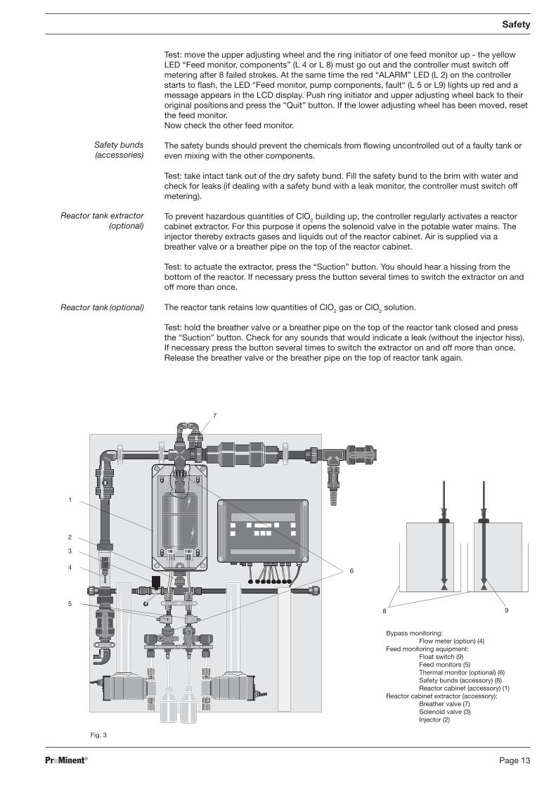
Test: move the upper adjusting wheel and the ring initiator of one feed monitor up - the yellowLED “Feed monitor, components” (L 4 or L 8) must go out and the controller must switch offmetering after 8 failed strokes. At the same time the red “ALARM” LED (L 2) on the controllerstarts to flash, the LED “Feed monitor, pump components, fault“ (L 5 or L9) lights up red and amessage appears in the LCD display. Push ring initiator and upper adjusting wheel back to theiroriginal positions and press the “Quit” button. If the lower adjusting wheel has been moved, resetthe feed monitor.Now check the other feed monitor.
The safety bunds should prevent the chemicals from flowing uncontrolled out of a faulty tank oreven mixing with the other components.
Test: take intact tank out of the dry safety bund. Fill the safety bund to the brim with water andcheck for leaks (if dealing with a safety bund with a leak monitor, the controller must switch offmetering).
To prevent hazardous quantities of ClO2 building up, the controller regularly activates a reactorcabinet extractor. For this purpose it opens the solenoid valve in the potable water mains. Theinjector thereby extracts gases and liquids out of the reactor cabinet. Air is supplied via abreather valve or a breather pipe on the top of the reactor cabinet.
Test: to actuate the extractor, press the “Suction” button. You should hear a hissing from thebottom of the reactor. If necessary press the button several times to switch the extractor on andoff more than once.
The reactor tank retains low quantities of ClO2 gas or ClO2 solution.
Test: hold the breather valve or a breather pipe on the top of the reactor tank closed and pressthe “Suction” button. Check for any sounds that would indicate a leak (without the injector hiss).If necessary press the button several times to switch the extractor on and off more than once.Release the breather valve or the breather pipe on the top of reactor tank again.
Bypass monitoring:Flow meter (option) (4)
Feed monitoring equipment:Float switch (9)Feed monitors (5)Thermal monitor (optional) (6)Safety bunds (accessory) (8)Reactor cabinet (accessory) (1)
Reactor cabinet extractor (accessory):Breather valve (7)Solenoid valve (3)Injector (2)
Fig. 3
Safety bunds(accessories)
Reactor tank extractor (optional)
Reactor tank (optional)
7
1
2
3
4
5
6
98
BA_BEZ_022_07_08_GB.p65 09.07.2008, 11:25 Uhr13

Page 14 ProMinent®
Equipment overview
3 Equipment overview(without safety equipment. See figure above.)
9 10
1 Injection valve (1.5 bar)2 Reactor3 Chemical reactor input valve, acid4 Feed monitor, acid5 Bleed tap, acid6 Measuring cylinder7 Metering pump, acid8 Bleed bottle, acid9 Foot valve, acid10 Bello Zon acid in component tank(accessory)
NOTE
For ease of understanding, shows only those system parts for the acid-metering line. Thecorresponding system parts for the chlorite metering line are positioned to the right, andarranged symmetrically with regard to the corresponding system acid parts.
11 Mixer (optional)12 Stopcocks in the bypass line13 Controller14 Insert bracket
Illustration above5 Hazard warning signsCDV fittings and fixtures kitNon-return valve (accessory)Fig. 5
Fig. 4
1
2
3
4
5
6
7
8
11
13
12
1412
BA_BEZ_022_07_08_GB.p65 09.07.2008, 11:25 Uhr14

Page 15ProMinent®
4 Function description
Chemical principle of the system
The Bello Zon® CDVb chlorine dioxide system operates according to the hydrochloric acid-chlorite process:hydrochloric acid + sodium chlorite = chlorine dioxide + sodium chlorite solution + water4HCl + 5NaClO2 = 4ClO2 + 5NaCl + 2H2O
The Bello Zon® system initially generates a 2 % chlorine dioxide solution (20 g/l ClO2) bycombining dilute hydrochloric acid and dilute sodium chlorite solution.As soon as it forms this solution is fed to the water which is being treated.
Function principle of the system
Two metering pumps meter the components Bello Zon® acid and Bello Zon® chlorite into thereactor. The components react to form ClO2 solution. The metering pumps simultaneously feedthis solution to an injection point (injection valve) in the bypass. A mixer can be connecteddownstream from the injection valve to combine the ClO2 solution homogeneously with the waterof the bypass. The dilute ClO2 solution reaches the discharge point where it meets the main waterflow and dilutes it to the ultimately effective concentration for the process.The controller calculates the stroke rates for the metering pumps from the quantity of ClO2
pumped and, where applicable, a set value. It also interprets the signals from the sensors of thesafety equipment and switches off metering if necessary.The Bello Zon® system’s ClO2 output can be manually adjusted (internal actuation) e.g. contactwater meter controlled (flow-dependent actuation) or e.g. controlled at a chlorine dioxidemeasurement point (control variable-dependent actuation) .
Function description
BA_BEZ_022_07_08_GB.p65 09.07.2008, 11:25 Uhr15

Page 16 ProMinent®
Belüftung
suction device
waste water
tap water,min.1 bar
Leitungswasser, min.1 bar
Absaugeinrichtung
Abwasser
reactor housing
aeration
Reaktorgehäuse
Function description
Fig. 6
Fig. 7
FIC
M
T
FSAL
water to be treatedaufzubereitendes Wasser
treated waterbehandeltes Wasser
reactor housing
flushing device sampling point
Spüleinrichtung Probenentnahmestelle
LSA-
dosing pump
Reaktorgehäuse
premixerVorvermischer
Dosierventil 1.5 bar
Reaktor
Dosierpumpe
SäureChloriteAcidChlorit
Bello Zon®Bello Zon®
Bypass
reactor
injection valve
LSA-
safety bunds recommendedSicherheitswanne empfohlen
FSALFSAL
BA_BEZ_022_07_08_GB.p65 09.07.2008, 11:25 Uhr16

Page 17ProMinent®
Operating modesOperating mode- “Internal actuation”The Bello Zon® system operates continuously at a fixed, constant ClO2 output.
Operating mode- “Flow-dependent actuation”The ClO2 output of the Bello Zon®-system changes in proportion to the signal of the flow meter(contact water meter, inductive flow meter. . . ) .
Operating mode “Control variable-dependant actuation”The ClO2 output of the Bello Zon®-system changes in relation to the value measured via the mAsignal of a controller (D1C and ClO2 or redox sensor) .
Safety equipmentThe safety equipment is described at the end of the safety section (section 2).
Controls and key functionsThe controls and key functions are described overleaf from the title page.
5 Setting
NOTE
The controls and key functions are described overleaf from the title page.Setting the operating code is described in the section entitled “Commissioning”.
Operating menu diagram
Configuration menu
Meter ing OFF
= request for access code
Metering OFF
Parameter?
Metering OFF
Configuration?Info level
Settings menu xPermanent display
Info displays
Menu item x
Settings menu x Menu item x
Parameters menu
START
STOP
START
STOP
The permanent display appears when metering is on.It shows the current ClO2 output, and the actuation type or the set ClO2 output or feed quantity.You can also switch to the info display using the “Change” button. You will then see:• the equipment Identcode• the hardware version• the software version• the active code
and depending on the actuation type:• the set ClO2 output• the actuation type
Function description / Settings
BA_BEZ_022_07_08_GB.p65 09.07.2008, 11:25 Uhr17

Page 18 ProMinent®
CIO2=52,7 g/hInternal control Metering OFF
Metering OFFParameter ?
ParameterMax. Dose
Max. Dose52 ,7 g/h
CDVb xAxxxxxDxxx 03/4.01 xxNNDxxx Gauge capacity in
litres of pump acidacid
Max.ClO2 = 52,7 g/hInternal control
Metering OFFConfiguration ?
STARTSTOP
xxx ,x ml
xxx ,x ml
Gauge capacity inlitres of pump chlorite
Settings
To alter any controller settings, metering must be off (“Start/Stop” button), the LCD display shows“Metering OFF” (the controller does not actuate the pumps and ignores all input signals).After pressing the “Enter” button you have the choice between adjusting the parameters orconfiguring the system.
NOTE
• If an appears in a display you can change the displayed value with the arrow buttons.• If a appears, you can use the “Suction” button to trigger an action.
5.1 Operating mode- “Internal actuation”
(The operating code is: AKTIVxx NNDxxx)The Bello Zon® system operates continuously with an adjustable, constant ClO2 output.
BA_BEZ_022_07_08_GB.p65 09.07.2008, 11:25 Uhr18

Page 19ProMinent®
Settings
Settings in the parameters menu:
Set the required ClO2 output to “Max. dose” with the arrow buttons
Gauge capacity in litres of the pumps (see section 6. 5). The info displays show the ClO2 output (values under “ClO2” and “max ClO2 ” are the same). Systems with optional operating code “Remote control input contact”: the pause dose is displayed under “ClO2” during a pause.
5. 2 Operating mode “Flow-dependent actuation”
(The operating code is: AKTIVxxxYDxxx with Y =K, F, 0 or 4) The ClO2 output of the Bello Zon®-systemchanges in proportion to the quantity indicated via the signal from the flow meter (contact watermeter, inductive flow meter...).
▲▲
Q= 47 m3/hCIO2=52,7 mg/l Metering OFF
Metering OFFParameter
ParameterClO2 feed quantity
ClO2 feed quantityxxx mg/l
CDVb xAxxxxxDxx03/4. 01 xx NN Parameter
Max. flowMax. flowxxx m3/h
Feed 0,61 mg/lExternal control
Metering OFFConfiguration
Gauge capacity inlitres of pump
acid
Gauge capacity inlitres of pump
chlorite
ParameterMin. flow
Min. flowxx, x m3/h
acidxxx ,x ml
chloritexxx ,x ml
STOPSTART
BA_BEZ_022_07_08_GB.p65 09.07.2008, 11:25 Uhr19

Page 20 ProMinent®
Settings
Settings in the parameters menu:
Set the ClO2 concentration -“ClO2 feed quantity” - with the arrow buttons (required ClO2
concentration = ClO2 concentration + decay.)
Press the “On” button in the menu item “Max. flow” until the numerical value no longer changes.If the actual maximum flow is clearly below this value it is sensible to enter this second value.
Set the minimal flow value in the menu item “Min. flow”.
WARNINGAnalogue flow meters (0/4 - 20mA) be sure to set a “Min. flow” rate greater than “0”.The Bello Zon®
system can otherwise meter ClO2 without any water to dilute it, which canlead to the build-up of an explosive concentration.
Gauge capacity in litres of the pumps (see section 6.5)
The info displays show the flow, the current ClO2 concentration and the maximum set ClO2
concentration (feed value).
Additional explanation: if the flow exceeds the max. set value the controller will keep the BelloZon® system ClO2 output constant and the concentration will consequently drop.If the flow drops below the minimum set value the controller will switch off the metering.
5. 3 Operating mode “Control variable-dependant actuation”
(The operating code is: AKTIVxxYxDxxx with Y =K, 0 or 4)
The ClO2 output of the Bello Zon®-system changes in relation to the control variable in proportionto the mA signal of a controller. (The controller - e.g. a D1C controller -can use the measuredvalue from a ClO2 sensor or a redox probe. )
Settings in the parameters menu:Set the maximum required ClO2 output in g/h under “Max. dose”Gauge capacity in litres of the pumps (see section 6.5).
The info displays show the current ClO2 output and the maximum set ClO2 output.
▲▲
▲▲
▲▲
Max.ClO2 = 76 g/hCIO2=52.7 g/h Metering OFF
Metering OFFParameter ?
ParameterMax. dose
Max. dosexxx ,x g/h
CDVb xAxxxxXDxxx03/4.01 xxNXDxxx Gauge capacity in
litres of pumpacid
Max.ClO2 = 76 g/hExternal control
Metering OFFConfiguration ?
acidxxx ,x ml
chloritexxx ,x ml
STOPSTART
Gauge capacity inlitres of pump
chlorite
BA_BEZ_022_07_08_GB.p65 09.07.2008, 11:25 Uhr20
Page 21ProMinent®
Commissioning
6 Commissioning
WARNING• Commissioning must be carried out by Customer Service.
• If the reactor is empty, do not use chemicals when starting up (including in the linesbetween component tanks and reactor) since ClO2 gas can build up in the reactor. If theClO2 concentration is 20g/l this gas may explode.Only once the reactor is full of water should you connect the component tanks.
• The maximum admissible operating pressure for the system must never be exceeded inany operating state.
• The entire installation must be free from leaks when operating at maximum operatingpressure.
• Open all stop taps and valves in the bypass before commissioning.
• Check all hydraulic connections.
• Check all electrical connections.
• Read this whole section through carefully before commissioning the equipment.
• The ProMinent service technician must instruct the operating and general maintenancestaff during commissioning.
Note for the operatorNote the following directives when commissioning this equipment:
a) Accident prevention regulations GUV 8.15 and/or VGB 65:Chlorinating systems must not be commissioned until they have been checked by a qualifiedengineer to ensure their fitness for service and been thoroughly checked for leaks.Chlorinating systems must be safety-checked by a qualified engineer before everyrecommissioning.Operation and maintenance of chlorinating systems and handling of the chemicals used in themmust be entrusted only to personnel who have been suitably instructed and who can be expectedto carry out their duties conscientiously.
b) The hazardous operating substances ordinance (Arb-StoffV) issued 11th February 1982BGBl. / p. 145
c) Requirements of starting chemicals: see Section 7.1
NOTE
• A “Commissioning log” form is included in the appendix.
• The access code for the Bello Zon® controller configuration menu is “1000”.
6.1 Installation - final steps
Check the condition of the hydraulic connections
Check the condition of the electrical connections
Connect the Bello Zon® system to the mains power supply (with 3 x1 mm2 cable).
6.2 Configuring controller
Ensure “Metering OFF” status (if necessary, press the “Start /Stop” button)
Set the configuration parameters and the active code depending on the required operatingmode at the controller:
1) Operating mode “Internal actuation”2) Operating mode “Flow-dependent actuation”3) Operating mode “Control variable-dependant actuation”
6.2.1 Operating mode- “Internal actuation”
The Bello Zon® system operates continuously at a set constant ClO2 output.
▲▲
▲▲
▲
BA_BEZ_022_07_08_GB.p65 09.07.2008, 11:25 Uhr21

Page 22 ProMinent®
CIO2=52,7 g/hInternal control Metering OFF
Metering OFFParameter ?
ParameterMax. Dose
Max. Dose52 ,7 g/h
CDVb xAxxxxxDxxx 03/4.01 xxNNDxxx Gauge capacity in
litres of pump acidacid
Max.ClO2 = 52,7 g/hInternal control
Metering OFFConfiguration ?
STARTSTOP
xxx ,x ml
xxx ,x ml
Gauge capacity inlitres of pump chlorite
Commissioning
Settings in the parameter menu:
Set the required ClO2 output to “Max. dose” with the arrow buttons.The info displays show the current ClO2 output and the maximum set ClO2 output (in the case ofsystems with analogue remote control, these values are not the same) .
Settings in the configuration menu:
The active code is: xx NN Dxxx
Set the other active code-characteristics depending on the accessories fittedChange the suction interval and suction duration if necessary.
6.2.2 Operating mode- “Flow-dependent actuation”
The ClO2 output of the chlorine dioxide system changes in proportion to the signal of the flowmeter (contact water meter, inductive flow meter. . . ).
▲▲
▲
Metering OFFConfiguration
Configurationxxxx access code AKTIV xxNNDxxx
Doseduring pause
Pause dosexx %
SuctionSuction interval
Suction interval xx minutes
SuctionSuction duration
Suction duration xx seconds
Start upStart up
tt minutes
Metering OFFParameter ?
Operating code-option “Remote control input contact“ only
BA_BEZ_022_07_08_GB.p65 09.07.2008, 11:25 Uhr22

Page 23ProMinent®
Set the ClO2 concentration to “ClO2 feed quantity” with the arrow buttons.ClO2 concentration =required ClO2 -concentration + decay)
In the menu item “Max. flow” press the “On” button until the numerical value no longerchanges. If the actual maximum flow is clearly below this value it is sensible to enter thissecond value.
Set the minimum flow value in the menu item “Min. flow“.
WARNING
Analogue flow meters (0/4-20mA) -be sure to set a “Min. flow” value greater than“0”.The Bello Zon®
system can otherwise meter ClO2 without any water to dilute it, which canlead to the build-up of an explosive concentration.
Gauge capacity in litres of the pumps (see section 6.5)
To select the right water meter follow this rule(DP = pulse interval of water meter) :DPmin < DP < DPmax
where
DPmax output (g/h) / concentration (mg/l),DPmin DPmax /10
Settings in the parameters menu:
Commissioning
~=~=
▲▲
▲▲
Q= 47 m3/hCIO2=52,7 mg/l Metering OFF
Metering OFFParameter
ParameterClO2 feed quantity
ClO2 feed quantityxxx mg/l
CDVb xAxxxxxDxx03/4. 01 xx NN Parameter
Max. flowMax. flowxxx m3/h
Feed 0,61 mg/lExternal control
Metering OFFConfiguration
Gauge capacity inlitres of pump
acid
Gauge capacity inlitres of pump
chlorite
ParameterMin. flow
Min. flowxx, x m3/h
acidxxx ,x ml
chloritexxx ,x ml
STOPSTART
BA_BEZ_022_07_08_GB.p65 09.07.2008, 11:25 Uhr23

Page 24 ProMinent®
Commissioning
Example:
e.g. the ClO2 system is set to the maximum output =129 g/h and the concentration in the watermain (possibly downstream from a reaction tank) is 1.5 ppm ClO2.
At maximum ClO2 output the following applies:DPmax 129 / 1.5 86 litres/pulseDPmin = 86 / 10 9 litres/pulse
NOTEThe pulse interval can be adjusted with most water meters.
The permanent display and the info displays show the flow, the current output and the set feedvalue. If the flow exceeds the maximum value the ClO2 output remains constant and the feed valuefalls. If the flow drops below the minimum set value, the controller will switch off the metering.
Settings in the configuration menu:
Metering OFFConfiguration
Configurationxxxx access code AKTIV xxxKDxxx
Flow signalWater meter
Pulse intervalxxx ,x litres
Flow signalFrequency
Frequencyxxx pulses./l
Flow signalAnalogue
Q at 20 mA xxx m3/h
Metering OFFParameter ?
doseduring pause
Pause dosexx %
SuctionSution interval
Suction intervalxx minutes
SuctionSution duration
Suction duration xx seconds
Start upStart up
tt minutes
Operating code-option “Remote control input contact” only
AKTIV xxxFDxxx
AKTIV xxxODxxx
or
or
Set the active code characteristic “Flow input” to K, F, 0 or 4
Set the other active code-characteristics depending on the optional accessories fitted
In the following menu item set:
• with active code-characteristic “Flow input” = K: the pulse interval of water meter
• with active code-characteristic “Flow input” = F: the pulse value (frequency) of the flow meter
• with active code-characteristic “Flow input” = 0 or 4: the maximum measured flow at 20 mA(the controller sets the flow value for 0/4 mA to 0) .
Change the suction interval and suction duration if necessary.
~= ~=~=
▲▲
▲▲
BA_BEZ_022_07_08_GB.p65 09.07.2008, 11:25 Uhr24

Page 25ProMinent®
Commissioning
6.2.3 Operating mode “Control variable-dependant actuation”The ClO2 output of the Bello Zon®system changes in relation to the value measured via the mAsignal of a ClO2 or redox measuring point.
Settings in the parameters menu:
Set the maximum required ClO2 output in g/h(the controller calculates internally the minimal feed rate of the pumps from the setmaximum ClO2 output)
- Gauge capacity in litres of the pumps (see section 6.5).The info displays show the current ClO2 concentration and the maximum set ClO2 output.
Settings in the configuration menu:▲
▲
Metering OFFConfiguration
Configurationxxxx access code AKTIV xxNXDxxx
Control variableMax. frequency
Max.frequency
xxx Imp/Min
Metering OFFParameter ?
doseduring pause
Pause dosexx %
SuctionSuction interval
Suction durationxx minutes
SuctionSuction duration
Suction duration xx seconds
Start upStart up
tt minutes
Operating code-option “Remote control input contact”only.
Max.ClO2 = 76 g/hCIO2=52.7 g/h Metering OFF
Metering OFFParameter ?
ParameterMax. dose
Max. dosexxx ,x g/h
CDVb xAxxxxXDxxx03/4.01 xxNXDxxx Gauge capacity in
litres of pumpacid
Max.ClO2 = 76 g/hExternal control
Metering OFFConfiguration ?
acidxxx ,x ml
chloritexxx ,x ml
STOPSTART
Gauge capacity inlitres of pump
chlorite
BA_BEZ_022_07_08_GB.p65 09.07.2008, 11:25 Uhr25

Page 26 ProMinent®
Set the active code characteristic “Control variable input” to K, F, 0 or 4
Set other active code-characteristics depending on the optional accessories present
If the active code-characteristic “Control variable input” = K, enter the control variable pulsevalue.
Change the suction interval and suction duration if necessary.
6.3 Starting up the system
Place each suction lance in a separate bucket filled with clean water
Turn the bleed cock handle to the “Bleed” position (see Fig. 8)
If “Remote control input contact” in the operating code is O or C: in the case of “Meteringduring pause” always enter “0” under pause dose (configuration menu)
Set in the menu item “Start up xx minutes” 30 minutes and press the “Suction” button
Set the metering pump stroke length to 100 %
Let the metering pumps feed until the intake lines and liquid end are full and contain no bubbles.
Stop the metering pumps by pressing the “Suction” button
Turn the air bleed cock handles to the “Commissioning” position (see Fig. 8)
Open the stopcocks in the bypass
Set 60 minutes in the menu item “Start up xx minutes” and press “Suction” buttonWait until the remaining lines and the reactor are full of water and the Bello Zon® system isworking at the normal operating pressure.
NOTE
During start, the metering pump “chlorite” stops after 8 strokes, the metering pump “acid”continues to operate.
WARNINGNever combine the contents of the bleed bottles.
Never pour the contents of the bleed bottles back into the component tanks. The danger ofconfusion is too great.
Never swap over the bleed bottles.
This will cause the production of toxic ClO2 gas.
Pour the contents of the bleed bottles separately down the drain and rinse away each withplenty of water.
IMPORTANTIf conducting several bleeding operations, one after the other, watch the level of the bleedbottles.
Commissioning
▲▲
▲▲
▲▲
▲▲
▲▲
▲▲
▲▲
Fig. 8
Commissioning Bleeding
BA_BEZ_022_07_08_GB.p65 09.07.2008, 11:25 Uhr26

Page 27ProMinent®
Commissioning
6.4 Checking for tightness
WARNING
Remedy leaks immediately by suitable means.A vacuum may otherwise form in the ClO2 solution in the reactor, in which case the ClO2 willeffervesce and may explode.
Check all system parts for tightness at maximum operating pressure during start up
Remedy any leaks immediately by suitable means.
Press the “Suction” button to end the start-up process.
6.5 Discharging metering pumps
Before discharging, the metering pumps must have reached the operating temperature (afterapprox. 1h at maximum stroke rate).
Set both metering pumps to the same stroke length (minimum values see table. 3)
Access the settings menu “Gauge capacity in litres of pump, acid” and press the “Enter” button- the “acid tt min” menu option appears.
Press the “Down” button until the numerical value no longer changes - this gives the minimumvolume for capacity gauging of the “Acid” pump
NOTE
If this minimum volume is not reached in the subsequent capacity gauging process,increase either the stroke length of both metering pumps or the feed rate of the CDVsystem or reduce the maximum flow value in the bypass.
Not at initial commissioning: place each suction lance in a separate bucket filled with cleanwater (this will rinse away the chemical-residues and prevent the suction lances running empty)
IMPORTANT
Never put both suction lances in the same bucket.This can cause toxic ClO2 gas to be produced.
Place the calibrating cylinder on a level, even surface for easier reading (the fluid level shouldbe easy to read off)
Fill both calibrating cylinders with water to the top marking (500 ml and/or 1000 ml)
Place each suction lance carefully into its calibrating cylinder - slowly raise the suction lance,hold vertical: do not allow air in the suction lances to interfere with the discharging.
Set both bleed taps to “Commissioning” (see Fig. 8)
Start the capacity gauging process by pressing the “Suction” button - the controller allows themetering pumps to carry out a preset number of strokes (duration up to 1.5 -12 min)
NOTE
Both metering monitors are active during measurement of the capacity. Should a faultoccur at this point, the flow monitor must be reset (see section 6.6) and repeat the capacitygauging process with a refilled measuring cylinder.
Withdraw the suction lances from the calibrating cylinders (slowly raise while holding vertical)and place each in its bucket
Place the calibrating cylinder on a level, even surface for easier reading (the fluid level shouldbe easy to read off)
Read off the new values from the calibrating cylinder.
▲▲
▲▲
▲▲
▲▲
▲▲
▲▲
▲▲
▲
BA_BEZ_022_07_08_GB.p65 09.07.2008, 11:25 Uhr27

Page 28 ProMinent®
1 Upper adjusting wheel2 Ring initiator3 Lower adjusting wheel
1
2
3
Fig. 9 Table 2
Constitute the difference between the first value and the new value (in ml) for acid - the value mustbe greater than the minimum volume but not by more than 30 % (take minimum volume times 1.3)
Enter the new value for acid into the controller with the arrow buttons
Press the “Enter” button until the “Gauge capacity in litres of pump Chlorite” menu option appears
Calculate the difference between the first value and the new value (in ml) for chlorite - the valuemust be greater than the minimum volume but not more than 30 % more (take minimum volumetimes 1.3)
Enter the new value for acid into the controller with the arrow buttons
Press the “Enter” button until the “Gauge capacity in litres of pump, chlorite” menu option appears
Calculate the difference between the first value and the new value (in ml) for chlorite - the valuemust be greater than the minimum volume but not more than 30 % more (take minimum volumetimes 1.3)
Enter the new value for chlorite into the controller with the arrow buttons
Press “Enter” to save
Enter the values for acid and chlorite in the Commissioning log/System logbook
Exit the configuration menu by pressing the “Return” button - “Metering OFF Configuration?”appears in the LCD display?
Set both bleed taps to “Normal operation” (see Fig. 8)
Not at initial commissioning: place the suction lance for the acid carefully into the “Acid” drum andattach
Place the suction lance for the chlorite carefully into the “Chlorite” drum and attachRinse the calibrating cylinders and buckets thoroughly
Pour the contents of the bleed bottles separately down the drain and rinse away each with plenty ofwater.
WARNING
Never swap over the bleed bottles.Never combine the contents.Never pour the contents of the bleed bottles back into the component tanks. The danger ofconfusion is too great.This will cause the production of toxic ClO2 gas.
6.6 Setting feed monitor
WARNING
• Never leave the ring initiators in the lowest position.The feed monitors cannot otherwise carry out their safety function during metering.
• The stroke lengths of the metering pumps must be greater than the minimum value in Tab. @.The feed monitors cannot otherwise carry out their safety function during metering.
IMPORTANT
Always adjust feed monitors at normal operating pressure.
Stroke length table, minimum valuesCDV 15 70 %CDV 35 60 %CDV 60 50 %CDV 120 50 %CDV 220 40 %CDV 600 40 %CDV 2000 30 %
Commissioning
▲▲
▲▲
▲▲
▲▲
▲▲
▲▲
▲▲
▲
BA_BEZ_022_07_08_GB.p65 09.07.2008, 11:25 Uhr28

Page 29ProMinent®
Commissioning
Switch off metering with the “Start/Stop” button
Screw the upper adjusting wheels (1) on the feed monitors (see Fig. @) right to the top
Do the same with the ring initiators (2) and lower adjusting wheels (3)
Start the metering pumps with the “Suction” button - they will run for 20 strokes
Lower the ring initiators (2) slowly until the green LEDs “Feed monitor, acid” (L 6) and “Feedmonitor, Chlorite” (L 10) (see Fig. @) light up at each stroke precisely with no error pulses
Then lower the ring initiators (2) approx. 2 mm
Screw the upper adjusting wheels (1) down to the ring initiators (2)
Stop the metering pumps by pressing the “Suction” button
Start metering with “Start/Stop” button.
The system now operates at the required feed rate (at initial commissioning, must still be with water).
6.7 Checking safety equipment
see section. 2 “Safety” “Description and checking of safety equipment”
6.8 Installing component containers
Switch off metering with the “Start/Stop” button - “Metering OFF” appears
Place the component tanks under the system (acid left (HCl, red), chlorite right
(NaClO2, blue) - viewed from the front)Immerse the suction lance in the component tank for acid (the foot valve should be hoveringjust above the bottom of the tank)
Screw on the lid
Install the suction lance for chlorite in the same way.
6.9 Checking chlorine dioxide generation
Switch on metering with the “Start/Stop” button
After approx. 1 h prepare a sample from the water main (downstream from a reaction tank, ifpresent or at a ClO2 metering point) - the ClO2 solution must have reached this point by now
Take the sample in a clean container and displace immediately with the DPD 1 reagent (seeoperating instructions for your colorimetric measuring device; ClO2 tends to effervesce,particularly at water temperatures >25 °C.)
Quickly measure the ClO2 content of the sample with a colorimetric meter (e. g. with a DT 1photometer)
Change the maximum ClO2 output and/or feed quantity in the parameters menu if necessary,run the system and repeat the measurement after a sufficient time has elapsed.
WARNING
• If you have to change the stroke length you must calibrate the metering pumps and readjust the feed monitors.
• Observe national and local directives with regard to the ClO2 concentrations.
6.10 Setting pause metering
If “Remote control input contact” in the operating code is at O or C: for “Metering during pau-se”, enter a value under Pause dose if necessary (Configuration menu).
The Bello Zon® system is now ready to run.
▲▲
▲▲
▲▲
▲▲
▲▲
▲▲
▲▲
▲▲
▲▲
▲▲
BA_BEZ_022_07_08_GB.p65 09.07.2008, 11:25 Uhr29

Page 30 ProMinent®
7 Operating
WARNING
• The maximum admissible operating pressure for the system must never be exceeded in any operating state.
• The entire installation must be free from leaks when operating at maximum operating pressure.
7.1 Replacing component container
WARNING
• The component container must be changed by trained staff only.Incorrect assembly can result in large quantities of toxic ClO2 gas being generated, oreven reactor explosion.
• Note colour code.Red stands for acid (HCl, left), blue for chlorite (NaClO2, right).
• Never pour chemicals back into component tanks or mix together.This can cause large amounts of toxic ClO2 gas to be produced.
• Never put both suction lances in the same bucket.This can cause toxic ClO2 gas to be generated.The two components, hydrochloric acid (HCl) and sodium chlorite (NaClO2), must neverbe combined except in the reactor.There will otherwise be a sudden formation of toxic ClO2 gas, which can be explosive.
• Make sure that the “acid” suction lance is fitted into the “acid” component tank and the“chlorite” suction lance is fitted in the “chlorite” component tank (check labels).
• Never operate the Bello Zon® CDVb chlorine dioxide system with undilute sodium chloritesolution.Otherwise highly concentrated ClO2-gas will form, which may explode in the reactor.
• Use only Bello Zon® chlorite or dilute sodium chlorite (NaClO2, 7, 5 ± 0.3 % by weight).
• If using dilute sodium chlorite (NaClO2, 7.5 ± 0.3 % by weight) ensure correct dilution at allcosts.
• Never confuse sodium chlorite (NaClO2) with chlorine bleach (NaOCl). Use only Bello Zon®
chlorite or dilute sodium chlorite (NaClO2, 7.5 ± 0.3 % by weight).
• Use only Bello Zon® acid or dilute hydrochloric acid (HCl, 9 +1.5 % by weight).
• If using dilute hydrochloric acid (HCl, 9 +1.5 by weight) ensure correct dilution at all costs.
• Do not use contaminated acid.It can contain organic chlorine compounds (EOX) which will attack the seals and makethe PVC lines brittle.
NOTE for the operatorIsrael only: use only fluoride-free chemicals.
Press the “Start /Stop” button - the LCD display must indicate “Metering OFF”
Lift each suction lance carefully out of its component tank (raise slowly, hold vertical)
Place each suction lance in a separate bucket filled with clean water (this will prevent suctionlances from running empty)
Seal the empty component tanks and dispose of correctly.
Place the new component tanks under the system (red stands for acid (left), bluefor chlorite (right))
Slowly raise each suction lance, hold vertical and immerse in the correct component tanks (redstands for acid, blue for chlorite.)
Check the intake pipe for air bubbles, bleed if necessary, (see 6.3)
Start metering with “Start/Stop” button.
Operating
▲▲
▲▲
▲▲
▲▲
BA_BEZ_022_07_08_GB.p65 09.07.2008, 11:25 Uhr30

Page 31ProMinent®
Operating
7.2 Bleeding metering pumps
Turn the air bleed cock handle to the “Bleed” position (see Fig. 8)
Press the “Suction” button and hold
Run the metering pumps until the intake lines and liquid end are full and without bubbles
If this does not happen, set the metering pump stroke length to 100 % (note values) and pressthe “Suction” button and hold - then gauge capacity in litres of metering pumps and set feedmonitors.
Turn the air bleed cock handle to the position “Commissioning” (see Fig. 8)
Pour the contents of the bleed bottles separately down the drain and rinse away each withplenty of water.
WARNING
Never swap over the bleed bottles.Never combine the contents.Never pour the contents of the bleed bottles back into the component tanks. The danger ofconfusion is too great.This will cause a large quantity of toxic ClO2 gas to be generated.
7. 3 Discharging metering pumps
Before discharging, the metering pumps must have reached the operating temperature (afterapprox. 1h at maximum stroke rate) .
Set both metering pumps to the same stroke length (minimum values see table 3)
Access settings menu “Gauge capacity in litres of pump, acid” and press “Enter” button -
”acid tt min” menu option appears.
Press the “Down” button until the numerical value no longer changes - this gives the minimumvolume for Gauge capacity in litres of the “acid” pump.
NOTE
If this minimum volume is not reached in the subsequent capacity gauging process,increase either the stroke length of both metering pumps or the feed rate of the CDVsystem or reduce the maximum flow value in the bypass.
Not at initial commissioning: place each suction lance in a separate bucket filled with cleanwater (this will rinse away the chemical residues and prevent suction lances from runningempty)
IMPORTANT
Never put both suction lances in the same bucket.This can cause toxic ClO2 gas to be generated.
Place the calibrating cylinder on a level, even surface for easier reading (the fluid level shouldbe easy to read off)
Fill both calibrating cylinders with water to the top marking (500 ml and/or 1000 ml)
Place each suction lance carefully into its calibrating cylinder - slowly raise the suction lance,hold vertical: do not allow air in the suction lances to interfere with the capacity gaugingprocess.
Set both bleed taps to the position “Commissioning” (see Fig. 8)
Start the capacity gauging process by pressing the “Suction” button - the controller allows themetering pumps to carry out a preset number of strokes (duration up to 1.5 -12 min)
▲▲
▲▲
▲▲
▲▲
▲▲
▲▲
▲▲
▲▲
BA_BEZ_022_07_08_GB.p65 09.07.2008, 11:25 Uhr31

Page 32 ProMinent®
Operating
NOTE
Both metering monitors are active during measurement of the capacity. Should a faultoccur at this point, the flow monitor must be reset (see section 7.5) and repeat the capacitygauging process with a refilled measuring cylinder.
Withdraw the suction lances from the calibrating cylinders (slowly raise while holding vertical)and place each in its bucket
Place the calibrating cylinder on a level, even surface for easier reading (the fluid level should beeasy to read off)
Read off the new values from the calibrating cylinder
Record the difference between the first value and the new value (in ml) for acid - the value mustbe greater than the minimum volume but not by more than 30 % (take minimum volumes times1.3)
Enter the new value for acid into the controller with the arrow buttons
Press the “Enter” button until the “Gauge capacity in litres of pump, chlorite” menu optionappears
Record the difference between the first value and the new value (in ml) for chlorite - the valuemust be greater than the minimum volume but not more than 30 % more (take minimumvolumes times)
Enter the new value for chlorite into the controller with the arrow buttonsPress “Enter” to save
Enter the values for acid and chlorite in the commissioning log/Appendix-Logbook
Exit the configuration menu by pressing the “Return” button - “Metering OFF Configuration?”appears in the LCD display.
Set both bleed taps to “Normal operation” (see Fig. 8)
Not at initial commissioning: place the suction lance for the acid carefully into the “acid” drumand attach
Place the suction lance for the chlorite carefully into the “Chlorite” drum and attach
Rinse the calibrating cylinders and buckets thoroughly
Pour the contents of the bleed bottles separately down the drain and rinse each with plenty ofwater.
WARNING
Never swap over the bleed bottles.Never combine the contents.Never pour the contents of the bleed bottles back into the component tanks. The danger ofconfusion is too great.This would cause a large quantity of toxic ClO2 gas to be generated.
7.4 Checking chlorine dioxide generation
Switch on metering with the “Start/Stop” button
After approx. 1 h prepare a sample from the water main (downstream from a reaction tank, ifpresent or at a ClO2 metering point) - the ClO2 solution must have reached this point by now
Take the sample in a clean container and displace immediately with the DPD 1 reagent (seeoperating instructions for your colorimetric measuring device; ClO2 tends to effervesce,particularly at water temperatures > 25 °C.)
Quickly measure the ClO2 level of the sample with a colorimetric meter (e. g. with a DT 1photometer)
Change the maximum ClO2 output and/or feed quantity in the parameters menu if necessary,run the system and repeat the measurement after a sufficient time has elapsed (1 hour or more).
WARNING
• If you have to change the stroke length you must calibrate the metering pumps andreadjust the feed monitors.
• Observe national and local directives with regard to the ClO2 concentrations.
▲▲
▲▲
▲▲
▲▲
▲▲
▲▲
▲▲
▲▲
▲▲
▲▲
BA_BEZ_022_07_08_GB.p65 09.07.2008, 11:25 Uhr32

Page 33ProMinent®
Operating
7.5 Feed monitor settings
WARNING
• Never leave the ring initiators in the lowest position. The feed monitors cannot otherwise carry out their safety function during metering.
• The stroke lengths of the metering pumps must be greater than the minimum value in Tab. 4. The feed monitors cannot otherwise carry out their safety function during metering.
IMPORTANT
Always adjust feed monitors at normal operating pressure.
Switch off metering with the “Start/Stop” button
Screw the upper adjusting wheel (1) on the feed monitors (see Fig. 10) right to the top
Do the same with the ring initiator (2) and lower adjusting wheels (3)
Start the metering pumps with the “Suction” button - they will run for 20 strokes
Lower the ring initiators (2) slowly until the green LEDs “Feed monitor, acid” (L 6) and “Feedmonitor, chlorite” (L 10) (see Fig. 1) light up exactly at each stroke.
There must be no error pulses.
Then lower the ring initiators (2) approx. 2 mm further
Screw the upper adjusting wheels (1) down to the ring initiators (2)
Stop the metering pumps by pressing the “Suction” button
start metering with “Start/Stop” button.
Measured value-dependent metering: check the sensors regularly (interval dependent on processconditions; see operating instructions manual for sensors).
▲▲
▲▲
▲▲
▲▲
Fig. 10 table 3
1 Upper adjusting wheel2 Ring initiator3 Lower adjusting wheel
1
2
3
stroke length table, minimum valuesCDV 15 70 %CDV 35 60 %CDV 60 50 %CDV 120 50 %CDV 220 40 %CDV 600 40 %CDV 2000 30 %
▲
BA_BEZ_022_07_08_GB.p65 09.07.2008, 11:25 Uhr33

Page 34 ProMinent®
What happens in the event of incorrect use?
8 What happens in the event of incorrect use?
a) Component tanksIncorrect use: component tanks have been swappedThe result: toxic ClO2 gas will form in the component tanks
Incorrect use: undilute acid and undilute chlorite have been used and the Bello Zon® system/thepumps startedThe result: the undilute chemicals will combine in the reactor, it will get very hot, toxic ClO2 gaswill form which may cause the reactor to explode.
b) Metering pumpsIncorrect use: different metering pump stroke lengths have been set and the feed monitors setaccordingly, no capacity gauging or wrong values specified for the capacity gaugingThe results:
• overdosing of acid or chlorite:Acid overdose: the existing acid overdose will be strengthened, the ClO2 solution diluted andconsequences will be minimal.
• Chlorite overdose: the ClO2 output will drop and the displayed ClO2 quantity will no longer becorrect.
c) Feed monitorsIncorrect use: ring initiator set too lowThe result: it is possible that the feed monitor will not recognise a reduction in the flow rate of> 30 % and metering will continue to run.
• Will cause overdosing of acid or chlorite:Acid overdose: the existing acid overdose will be strengthened, the ClO2 solution diluted andconsequences will be minimal.
• Chlorite overdose: the ClO2 output will drop and the displayed ClO2 quantity will no longer becorrect.
Incorrect use: ring initiator set too highThe result: the controller will switch off the metering after eight pump strokes.
d) BypassIncorrect use: the limit contact in bypass is set too lowThe result: the ClO2 concentration in bypass will be too high which can lead to environmental orhealth hazard.
Incorrect use: the limit contact in bypass is set too lowThe result: the ClO2 concentration in the bypass will be too high which can lead to environmentalor health hazard.
e) ControllerIncorrect use: incorrect calibration values setThe result: will cause overdosing of acid or chlorite:
• Acid overdose: the existing acid overdose will be strengthened, the ClO2 solution diluted andconsequences will be minimal.
• Chlorite overdose: the ClO2 output will drop and the displayed ClO2 quantity will no longer becorrect.
BA_BEZ_022_07_08_GB.p65 09.07.2008, 11:25 Uhr34
Page 35ProMinent®
9 Maintenance
WARNING
• The Bello Zon® system must be serviced every six months by ProMinent.In the worst case a vacuum can form in the undilute ClO2 solution in the reactor e.g. dueto a leak in one of the lines downstream.The reactor could then explode.
• Before all servicing work (exchange of parts etc.) flush the Bello Zon® system with waterto remove all traces of chemical from it and, above all, the reactor.
• Reactor cabinet only: Extract contents of reactor cabinet before opening.Press the “Suction” button (water should flow).
CAUTION
• Signal leads and mains connection cables must always be replaced by ProMinent serviceengineers.
• Only corresponding special leads may be used.
NOTE for the operator:According to the accident prevention regulation GUV 8.15 and/or VGB 65 § 19 (2) chlorine dioxidesystems must be safety-checked regularly, but at least once a year and before everyrecommissioning, by a qualified engineer.
This inspection can be carried out by the service technician within the context of the six-monthlyservice. We therefore recommend that you arrange a service contract.
9.1 Service by service technicians only
Every six months
9.1.1 Flush reactor, detoxify reactor contents
WARNING
• Wear suitable protective equipment for ClO2 gas, ClO2 solution, hydrochloric acid, sodiumchlorite and caustic soda (protective goggles, rubber gauntlets, gas mask, rubber apron...)!
• In the event of contact with one of these chemicals, rinse immediately with plenty of coldwater, consult a doctor if necessary.
• Observe national and local directives.
• The disassembly of an un-rinsed reactor is risky because air can get into the solution as itdrains out, which can quickly produce an explosive ClO2 gas. This measure is thereforeacceptable only in an emergency and also only if the reactor volume does not exceed 3litres.
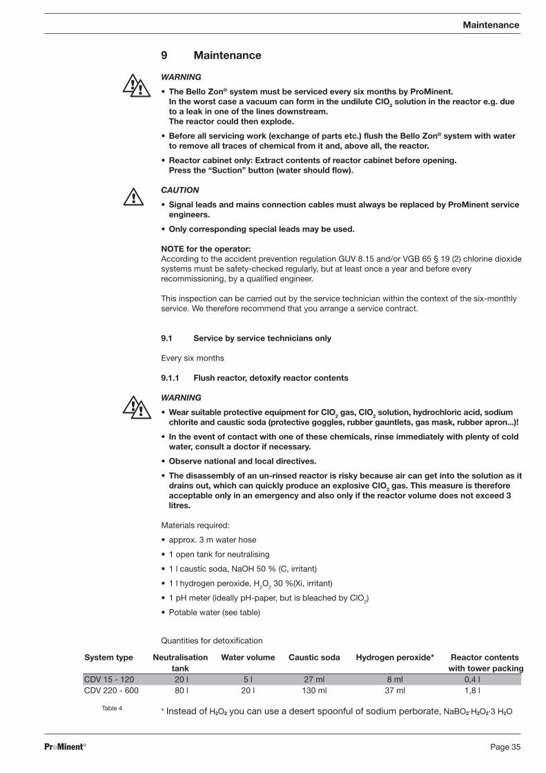
Materials required:
• approx. 3 m water hose
• 1 open tank for neutralising
• 1 l caustic soda, NaOH 50 % (C, irritant)
• 1 l hydrogen peroxide, H2O2 30 %(Xi, irritant)
• 1 pH meter (ideally pH-paper, but is bleached by ClO2)
• Potable water (see table)
Quantities for detoxification
* Instead of H2O2 you can use a desert spoonful of sodium perborate, NaBO2·H2O2·3 H2O
Maintenance
System type Neutralisation Water volume Caustic soda Hydrogen peroxide* Reactor contentstank with tower packing
CDV 15 - 120 20 l 5 l 27 ml 8 ml 0,4 lCDV 220 - 600 80 l 20 l 130 ml 37 ml 1,8 l
Table 4
BA_BEZ_022_07_08_GB.p65 09.07.2008, 11:25 Uhr35

Page 36 ProMinent®
Flushing reactorBefore dismantling components for servicing (reactor, metering lines, valves, seals, …) force thecontents of the discharge line and the reactor from bottom to the top with water. For thispurpose, either pump water from the intake side through the system or run the system with waterinstead of chemicals:
Switch off metering with the “Start /Stop” buttonSwitch to “Configure?” menuSet the “Run-in period” parameter to at least 30 min in the “Start up” settings menuDepressurise the bypass if possible. Close the stopcock upstream from the Bello Zon® systemand downstream from the flushing assemblyConnect a hose to the purge valve of the flushing assemblyInsert the hose into a tank containing neutralisation solution (see below ) - the hose must beimmersed below the liquid levelOpen the purge valvePlace each suction lance in a separate bucket filled with clean waterPress the “Suction” button and set the stroke lengths of both metering pumps to 100 %Run the Bello Zon® system until the pump’s liquid ends, the reactor and the lines up to theflushing assembly are filled with water
Detoxifying reactor contents(See also Tab. 5)
Once the reactor is completely empty, its contents must be diluted 10:1 in the neutralisation tank. Fill the neutralisation tank a quarter full with water while stirringAdd the quantity of caustic soda required for neutralising (protective equipment).Then add the calculated quantity of hydrogen peroxide while stirring (overdose is uncritical).If the ClO2 solution in the neutralisation tank does not colour immediately, carefully add anothercup-full of NaOH or H2O2 (the pH value must be over pH 8).
CAUTION
Add the alkaline flushing water to the neutralisation tank for neutralisation.
Carrying out emergency procedure:Fill the neutralisation tank with enough water to ensure that the reactor is completely covered.Dismantle the reactor (wearing protective equipment), lower into the neutralisation tank andplace both rapidly outdoors or at an exit.The unscrew the valves under water and lift the reactor up and down to allow the contents torun out into in the neutralisation tank.Add first the caustic soda and then the hydrogen peroxide to the tank contents (see Tab. 5),until the solution is colourless.If the ClO2 solution in the neutralisation tank does not colour immediately, carefully add anothercup-full of NaOH or H2O2 (the pH value must be over pH 8) .Let the reactor empty out into the neutralisation tank and rinse again with water if necessary.
9.1.2 Replacing consumables
WARNING
Disconnect the system from the power supply and prevent from being switched on again.
IMPORTANT
If the system is continuously run at maximum stroke rate, maximum back pressure and 100 %stroke length, the consumable parts on the metering pumps will need replacement morefrequently.If the system is run at a moderate load the consumable parts on the metering pumps willpossibly need replacement only once a year.
▲
Maintenance
▲▲
▲▲
▲▲
▲▲
▲▲
▲▲
▲▲
▲▲
▲▲
▲
BA_BEZ_022_07_08_GB.p65 09.07.2008, 11:25 Uhr36

Page 37ProMinent®
Replace the following consumables:• Pump diaphragms (see Fig. 11 and 12 )• All metering line seals (from the intake valve of the metering pumps to the system’s injection
valves- see Fig. 13 and 14)• Compression springs of injection valves (see Fig. 14 )
Replacing pump diaphragms
WARNING
• Protect yourself from the metering chemical.
• Depressurise the discharge line.
Empty the liquid end (flush liquid end thoroughly).Set the stroke length while Beta® is running at 0 % stroke (the driving axle is then fixed).Switch off the Beta®
Unscrew the hydraulic connections from the discharge and intake sides.Remove screws (1).(Just) slacken the liquid end (2) and head washer (4) from pump housing (6).Take hold of the housing (6) with one hand and clamp the diaphragm (3) with the other betweenthe liquid end (2) and the head washer (4). Slacken the diaphragm (3) on the driving axle bylightly screwing the liquid end (2) and head washer (4) anti-clockwise.Unscrew the diaphragm (3) completely from the driving axle.Remove the head washer (4) from the housing (6).Check the condition of the safety diaphragm (5) and replace if necessary.Push the safety diaphragm (5) onto the driving axle just until it is lying flat against the pumphousing (6) -no further.Screw new diaphragm (3) up to the stop onto the driving axle (6) - essential for the pump tometer precisely.Unscrew the diaphragm (3) once more.Place the head washer (4) onto the housing (6).
IMPORTANT
• The leakage bore must face downwards when the pump is subsequently installed (SeeFig. 11, arrow)
• Place the head washer (4) in exactly in the right position on the pump housing (6).Do not twist the head washer (4) on the pump housing (6), this will cause the safetydiaphragm (5) to distort.
Insert the diaphragm (3) into the head washer (4).
Hold tightly onto the head washer (4) and screw the diaphragm (3) clockwise until it is sittingfirmly (you will feel the return spring resistance).
IMPORTANT
• Do not over-screw the diaphragm (3)(particularly in the case of type 1001) .
• The head washer (4) must be in the right position to prevent the safety diaphragm fromdistorting (5).
Fit liquid end (2) with the screws (1) onto the diaphragm (3) and the head washer (4) (the intakeconnector must face downwards when the pump is in place).Tighten the screws (1) lightly and then tighten alternately (tightening torques, see below) .
Maintenance
▲▲
▲▲
Solenoid metering pumpsBeta® BT4a, BT5a
▲▲
▲▲
▲▲
▲▲
▲▲
▲▲
▲
BA_BEZ_022_07_08_GB.p65 09.07.2008, 11:25 Uhr37

Page 38 ProMinent®
1 2 3 4 5 6
1 Screws2 Liquid end3 Diaphragm4 Head washer5 Safety diaphragm6 Pump housingFig. 11
NOTE
• Check the tightening torques of the screws after 24 hours operation.
• PP liquid ends: check the tightening torques again after three months.
Tightening torques for the screws:Liquid end Ø 70 mm: 2.5 to 3 NmLiquid end Ø 90 mm and Ø 100 mm: 4, 5 to 5 Nm
Motor driven metering pumps ProMinent® Sigma S1Ca, S2CaChange gear oil after approx. 5000 operating hours.Gear oil ISO Viscosity grades VG 460 e.g. Mobil Gear 634,ProMinent Order no. 555325 (oil quantity approx. 0.5 l) .
Replace the diaphragms
IMPORTANT
Rinse liquid end first. Force water or suitable rinsing solution with a squeezy bottle throughthe intake connector of the liquid end.
Set stroke length to zero while the pump is running. Switch off the pump.
Undo the six screws from the liquid end and lift off with the screws.
Then slacken the diaphragms by twisting the push rod to the left and unscrew.
Screw on new diaphragms until seated firmly on the push rod. Place liquid end with screwswith the intake connector facing downwards (note direction of flow /arrows on the valves) . Switch on the pump. Set stroke length to 100 %, insert screws andtighten alternately to 4.5 ± 0.5 Nm (S1Ca) and/or 7.5 ± 0.5 Nm.Check pump for tightness at max. pressure.
▲▲
▲▲
Motor driven meteringpumps ProMinent®
Sigma S1Ca, S2Ca
➞
Maintenance
BA_BEZ_022_07_08_GB.p65 09.07.2008, 11:25 Uhr38

Page 39ProMinent®
*
4
3
21
Maintenance
Fig. 13
Fig. 12
NOTECheck the tightening torque of the liquid end screws after 24 hours in operation.
Replace all metering line seals
3
5
4
13
2
1
BA_BEZ_022_07_08_GB.p65 09.07.2008, 11:25 Uhr39

Page 40 ProMinent®
Assemblies with consumable seals for the “acid side” (numbers indicate the sectionaldrawings in the illustration below)
Sectional drawings with position of seals.Replace the seals on the “chlorite side” in the same way as for the “acid side”.
Replacing compression spring of injection valves.
IMPORTANT
Even in an unpressurised bypass line, the area between the reactor intake valves and theinjection valves is always under a priming pressure of approx. 1.5 bar.This area can be depressurised by slowly unscrewing the compression spring centre.
The injection valve compression spring is easy to remove after unscrewing the centre (see Fig. @)once the Bello Zon® system and bypass line are not under pressure.It is practically impossible for liquid to leak out and run through the system.
WARNING
Commission the Bello Zon® system and bypass line with water first and as far as the tightlyscrewed-in compression spring centre of the liquid end. Only then should you operate withacid and chlorite.
Maintenance
Fig. 14
842
849
844
862
366
864
843
843
842
853
367
840
842
BA_BEZ_022_07_08_GB.p65 09.07.2008, 11:25 Uhr40

Page 41ProMinent®
Changing gear oil (only S2Ca)
Change gear oil after approx. 5000 operating hours.Gear oil ISO 460 Viscosity grade VG 460 e. g. Mobil Gear 634,ProMinent Order no. 555325 (oil quantity approx. 0.5 l)
Further steps:
Recommission the system after completion of servicing (see section 6)
Check the system for leaks.
Check the safety equipment function (see “Safety” section) .
9.2 Regular checks, possible without service technicians(each day to each week, depending on the operating conditions).
Check ClO2 concentration in the treated water (observe national regulations)
Check and compare liquid levels of the component tanks,note “Liquid level low” warning in the display and have fresh componentsready if required.
Document the consumption of Bello Zon® acid and Bello Zon® chlorite (Systemlog book).
Check the flow rate in the bypass.
Check the system for leaks.
Maintenance of the metering pumpsCheck for:
• firm seating of the liquid end screws
• firm seating of discharge line (discharge / intake side)
• firm seating of pressure valve and intake valve
• Moisture at the leakage bore in the head washer (moisture indicates probable diaphragmrupture
• Press the “Suction” button to check that the metering pumps are feeding correctly.
10 Repair
WARNINGRepairs to the Bello Zon® system must be carried out by ProMinent service technicians.
11 Troubleshooting
Liquid is leaking from the head washer of a pumpCause: the liquid end is leaking at the pump diaphragmRemedy: tighten the Allen screws on the liquid end
If this does not work, notify ProMinent service technician.
Liquid is leaking from a air bleed cockCause: the internal seals are not pressed together hard enoughRemedy: depressurise the line and put on protective equipment
Detach the tubing from one of the opposite connections of the bleedtapPull the toggle off the air bleed cockTurn the toggle around and use as a tool to tighten the locking screwin the air bleed tap (left-hand thread).If this does not work, notify ProMinent-Service.
Maintenance / Repair / Troubleshooting
▲▲
▲▲
▲▲
▲▲
▲▲
▲▲
▲
BA_BEZ_022_07_08_GB.p65 09.07.2008, 11:25 Uhr41
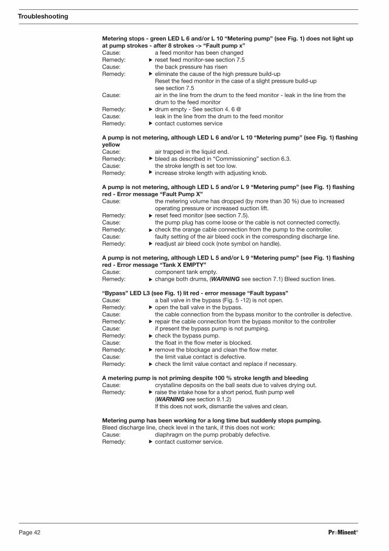
Page 42 ProMinent®
Metering stops - green LED L 6 and/or L 10 “Metering pump” (see Fig. 1) does not light upat pump strokes - after 8 strokes -> “Fault pump x”Cause: a feed monitor has been changedRemedy: reset feed monitor-see section 7.5Cause: the back pressure has risenRemedy: eliminate the cause of the high pressure build-up
Reset the feed monitor in the case of a slight pressure build-upsee section 7.5
Cause: air in the line from the drum to the feed monitor - leak in the line from thedrum to the feed monitor
Remedy: drum empty - See section 4. 6 @Cause: leak in the line from the drum to the feed monitorRemedy: contact customes service
A pump is not metering, although LED L 6 and/or L 10 “Metering pump” (see Fig. 1) flashingyellowCause: air trapped in the liquid end.Remedy: bleed as described in “Commissioning” section 6.3.Cause: the stroke length is set too low.Remedy: increase stroke length with adjusting knob.
A pump is not metering, although LED L 5 and/or L 9 “Metering pump” (see Fig. 1) flashingred - Error message “Fault Pump X”Cause: the metering volume has dropped (by more than 30 %) due to increased
operating pressure or increased suction lift.Remedy: reset feed monitor (see section 7.5).Cause: the pump plug has come loose or the cable is not connected correctly.Remedy: check the orange cable connection from the pump to the controller.Cause: faulty setting of the air bleed cock in the corresponding discharge line.Remedy: readjust air bleed cock (note symbol on handle).
A pump is not metering, although LED L 5 and/or L 9 “Metering pump” (see Fig. 1) flashingred - Error message “Tank X EMPTY”Cause: component tank empty.Remedy: change both drums, (WARNING see section 7.1) Bleed suction lines.
“Bypass” LED L3 (see Fig. 1) lit red - error message “Fault bypass”Cause: a ball valve in the bypass (Fig. 5 -12) is not open.Remedy: open the ball valve in the bypass.Cause: the cable connection from the bypass monitor to the controller is defective.Remedy: repair the cable connection from the bypass monitor to the controllerCause: if present the bypass pump is not pumping.Remedy: check the bypass pump.Cause: the float in the flow meter is blocked.Remedy: remove the blockage and clean the flow meter.Cause: the limit value contact is defective.Remedy: check the limit value contact and replace if necessary.
A metering pump is not priming despite 100 % stroke length and bleedingCause: crystalline deposits on the ball seats due to valves drying out.Remedy: raise the intake hose for a short period, flush pump well
(WARNING see section 9.1.2)If this does not work, dismantle the valves and clean.
Metering pump has been working for a long time but suddenly stops pumping.Bleed discharge line, check level in the tank, if this does not work:Cause: diaphragm on the pump probably defective.Remedy: contact customer service.
Troubleshooting
▲▲
▲▲
▲▲
▲▲
▲▲
▲▲
▲▲
▲▲
▲
BA_BEZ_022_07_08_GB.p65 09.07.2008, 11:25 Uhr42
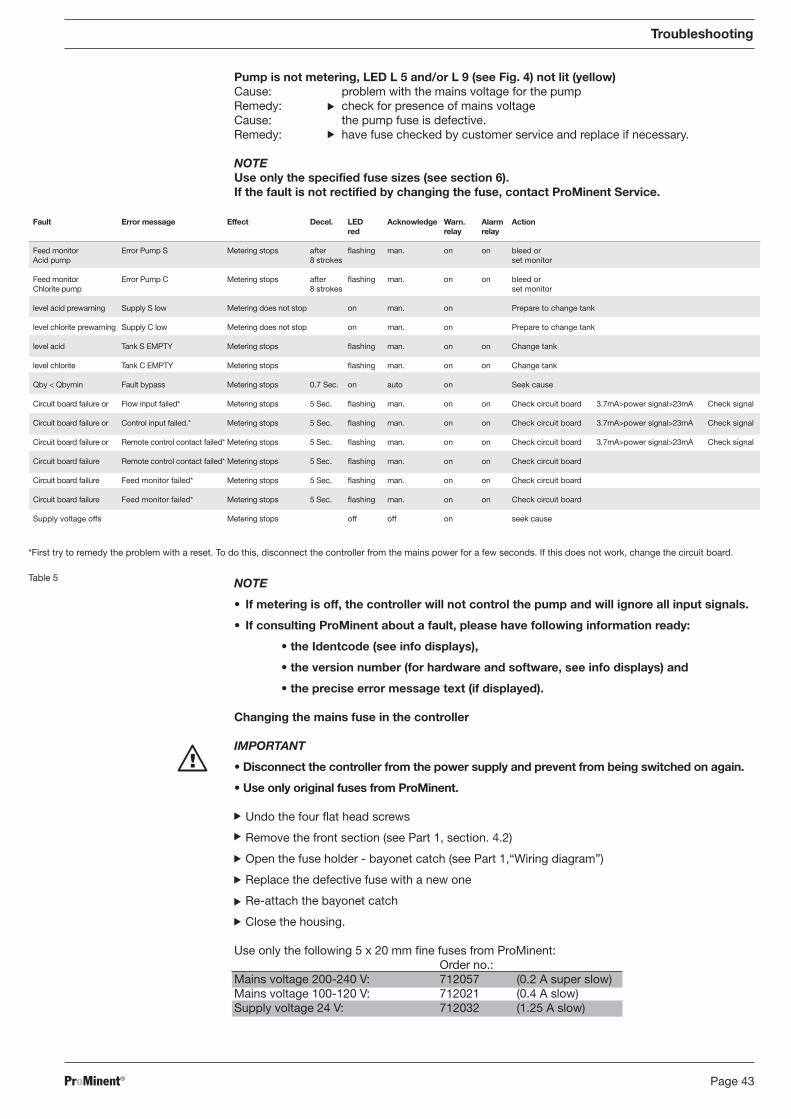
Page 43ProMinent®
Troubleshooting
▲▲
▲
Table 5
*First try to remedy the problem with a reset. To do this, disconnect the controller from the mains power for a few seconds. If this does not work, change the circuit board.▲
▲▲
▲▲
Pump is not metering, LED L 5 and/or L 9 (see Fig. 4) not lit (yellow)Cause: problem with the mains voltage for the pumpRemedy: check for presence of mains voltageCause: the pump fuse is defective.Remedy: have fuse checked by customer service and replace if necessary.
NOTEUse only the specified fuse sizes (see section 6).If the fault is not rectified by changing the fuse, contact ProMinent Service.
NOTE
• If metering is off, the controller will not control the pump and will ignore all input signals.
• If consulting ProMinent about a fault, please have following information ready:
• the Identcode (see info displays),
• the version number (for hardware and software, see info displays) and
• the precise error message text (if displayed).
Changing the mains fuse in the controller
IMPORTANT
• Disconnect the controller from the power supply and prevent from being switched on again.
• Use only original fuses from ProMinent.
Undo the four flat head screws
Remove the front section (see Part 1, section. 4.2)
Open the fuse holder - bayonet catch (see Part 1,“Wiring diagram”)
Replace the defective fuse with a new one
Re-attach the bayonet catch
Close the housing.
Use only the following 5 x 20 mm fine fuses from ProMinent:Order no.:
Mains voltage 200-240 V: 712057 (0.2 A super slow)Mains voltage 100-120 V: 712021 (0.4 A slow)Supply voltage 24 V: 712032 (1.25 A slow)
Fault Error message Effect Decel. LED Acknowledge Warn. Alarm Actionred relay relay
Feed monitor Error Pump S Metering stops after flashing man. on on bleed orAcid pump 8 strokes set monitor
Feed monitor Error Pump C Metering stops after flashing man. on on bleed orChlorite pump 8 strokes set monitor
level acid prewarning Supply S low Metering does not stop on man. on Prepare to change tank
level chlorite prewarning Supply C low Metering does not stop on man. on Prepare to change tank
level acid Tank S EMPTY Metering stops flashing man. on on Change tank
level chlorite Tank C EMPTY Metering stops flashing man. on on Change tank
Qby < Qbymin Fault bypass Metering stops 0.7 Sec. on auto on Seek cause
Circuit board failure or Flow input failed* Metering stops 5 Sec. flashing man. on on Check circuit board 3.7mA>power signal>23mA Check signal
Circuit board failure or Control input failed.* Metering stops 5 Sec. flashing man. on on Check circuit board 3.7mA>power signal>23mA Check signal
Circuit board failure or Remote control contact failed* Metering stops 5 Sec. flashing man. on on Check circuit board 3.7mA>power signal>23mA Check signal
Circuit board failure Remote control contact failed* Metering stops 5 Sec. flashing man. on on Check circuit board
Circuit board failure Feed monitor failed* Metering stops 5 Sec. flashing man. on on Check circuit board
Circuit board failure Feed monitor failed* Metering stops 5 Sec. flashing man. on on Check circuit board
Supply voltage offs Metering stops off off on seek cause
BA_BEZ_022_07_08_GB.p65 09.07.2008, 11:25 Uhr43

Page 44 ProMinent®
12 Decommissioning
WARNING
• Never combine the contents of the component tanks. This would cause a large quantityof toxic, explosive ClO2 gas to be generated.
• Never pour the contents of the vent bottles back into the component tanks. The danger ofconfusion is too great.This would cause a large quantity of toxic, explosive ClO2 gas to be generated.
• Never place both suction lances together or one after the other into the same bucket.This would cause a large quantity of toxic, explosive ClO2 gas to be generated.
• Never adjust air bleed cocks Corrosive chemicals may leak out.
12.1 For a short period
To decommission the Bello Zon® system for a short time only, simply press the “Start /Stop”button (“Metering STOP” appears). You do not need to disconnect the power supply for thesystem controller. The power supply to a chlorine dioxide metering point, if present, may not becut off for longer than 2 h.
12.2 For a longer period
Chlorine dioxide is an unstable compound which breaks down over time. If decommissioning theBello Zon® system for several days you should flush out the reactor with water.Use the flushing assembly in the bypass line (see Fig. 7, part 1).
Flush reactor, detoxify reactor contents
WARNING
• Wear suitable protective equipment for ClO2 gas, ClO2 solution, hydrochloric acid, sodiumchlorite and caustic soda (protective goggles, rubber gauntlets, gas mask, rubber apron. . . )!In the event of contact with one of these chemicals, rinse immediately with plenty of coldwater.
• Observe national and local directives.
• Never leave the reactor contents in a toxic state. The ClO2 solution will form an explosive ClO2
gas in a short time.
Materials required
• Approx. 3 m hose
• 1 tank for neutralisation (see Table)
• 1 l caustic soda 50 % (C, corrosive)
• 1 l hydrogen peroxide 30 %(Xi, irritant)
• 1 pH meter (ideally pH-paper, but is bleached by ClO2)
• Potable water (see table)
Decommissioning
* Instead of H2O2 you can use a desert spoonful of sodium perborate, NaBO2·H2O2·3 H2OTable 6
Quantity specifications for detoxification
System type Neutralisation Water volume Caustic soda Hydrogene peroxide* Reactor contentstank with tower packing
CDV 15 - 120 20 l 5 l 27 ml 8 ml 0.4 lCDV 220 - 600 80 l 20 l 130 ml 37 ml 1.8 l
BA_BEZ_022_07_08_GB.p65 09.07.2008, 11:25 Uhr44

Page 45ProMinent®
Decommissioning
Flushing reactorBefore dismantling the Bello Zon® system, force the contents of the discharge line and thereactor from the bottom to the top with water. For this purpose, either pump water from theintake side through the system or run the system with water instead of the chemicals:
Switch off metering with the “Start /Stop” button
Switch to “Configure?” menu
Set the “Run-in period” parameter to at least 30 min in the “Start up” settings menu
Place each suction lance in a separate bucket filled with clean water
Connect a hose to the purge valve of the flushing assembly
Insert the hose into a tank containing in neutralisation solution (see below)
Open the purge valve
Press the “Suction” button and set the stroke lengths of both metering pumps to 100 %
Run the Bello Zon® system until the pump liquid ends, the reactor and the lines as far as theflushing assembly are filled with water (during disassembly this will prevent ClO2 solution fromflowing out of the reactor)
Disconnect the system completely from the mains power supply.
Detoxifying reactor contents
After emptying the reactor, dilute its contents at least 10:1 in the neutralisation tank provided.Fill the neutralisation tank a quarter full with water before flushing process.
Add the quantity of caustic soda required for neutralising while stirring (protective equipment).
Then add the calculated quantity of hydrogen peroxide while stirring (overdose is uncritical). Ifthe yellowish-green solution does not immediately discolour, check the pH value: it must beabove pH 8 - if necessary correct with more caustic soda.
CAUTION
Add the alkaline flushing water to the neutralisation tank for neutralisation.
In the final stage, allow ClO2-free water to run through the bypass for about 5 min.
12.3 Preparing for frost-proof storage
Should you need to winterise the Bello Zon® system you must empty the reactor and bypass linecompletely. For this you need to fully reconnect the Bello Zon® system.Emptying reactor:
WARNING
Flush reactor for least 30 min (see “Decommissioning for a longer period”). Otherwise toxicClO2 solution or ClO2 gas can leak out.
Flush the system with water (see “Decommissioning for a longer period”)
Open the ball check valve at the reactor outlet/bypass
CAUTION
If a reactor cabinet is present: Before dismantling the intake valves on the bottom of thereactor, press the “Suction” button, to extract the remaining ClO2 gas from the reactorcabinet.
Dismantle the intake valves on the bottom of the reactor and empty the reactor.
▲▲
▲▲
▲▲
▲▲
▲▲
▲▲
▲▲
▲▲
▲
BA_BEZ_022_07_08_GB.p65 09.07.2008, 11:25 Uhr45

Page 46 ProMinent®
Disposal / Technical data
13 Disposal
WARNING
Flush the whole Bello Zon® system with water (see “Decommissioning”). If necessary, flush
the empty component tanks as well.The Bello Zon®
system may otherwise still contain hydrochloric acid (HCl), sodium chlorite(NaClO2) and chlorine dioxide (ClO2).
IMPORTANT
Observe all relevant disposal directives for your area (particularly with regard to electronicwaste).
14 Technical data
Ambient conditions for storage and transport:Temperature: -10 °C to +40 °CHumidity: < 92 % relative humidity, non condensingSunlight: protect from direct sunlight
Operating temperatures:Admissible ambient temperature range: +10 °C to +40 °CAdmissible temperature of water to be treated: +2 °C to +40 °CAdmissible component temperature (chemicals)*: +10 °C to +40 °C
*You may require heating systems for the chemical lines if ambient temperatures are below 15 °C when working at maximum stroke rate and 100 % stroke length.
Maximum admissible temperatures for bypass water
Bypass material PVC-U Bypass material PVC-CMax. adm. operating Max. adm. Max. adm. operating Max. adm.pressure in bar temperature in °C pressure in bar temperature in °C10 40 10 508 45 8 572.5 60 3.5 80*
* At higher temperatures the dissolved chlorine dioxide is extracted in the open.
The set-up location must be well-ventilated.
Contact and moisture protection•Controller: IP 65•Solenoid valve, extractor system: IP 65•Bypass pump: IP 54 (stainless steel)
(IP 44 (cast iron) )
Sound pressure level<70 dB(A) at maximum output (without bypass pump)
Table 7
BA_BEZ_022_07_08_GB.p65 09.07.2008, 11:25 Uhr46

Page 47ProMinent®
Technical data
Tabelle 8
Bello Zon® Chlorine Max. operating- Max. Feed rate Metering Max. pump Dimensions Weight.## PowerCDVa dioxide operating temperature stroke rate per pump priming (HxWxD)# (max.)### draw
metering* pressure rate component* type lift in**Type g/h bar °C strokes/h l/h Bello Zon® mwh mm kg 230 V 115 V 24 V
versionCDVa 15 15 8 10-40 10800 0,38 BT4 - 1000 1,8 900x1160x210 18,8 2,7 A 8,4 A 6,4 A
CDVa 35 46 8 10-40 10800 1,15 BT4 - 1001 2,0 900x1160x210 18,8 2,7 A 8,4 A 6,4 A
CDVa 60 66 8 10-40 10800 1,65 BT4 - 1002 2,5 900x1160x210 18,8 2,7 A 8,4 A 6,4 A
CDVa 120 130 8 15-40 10800 3,25 BT4 - 1005 3,0 900x1160x210 19,2 2,7 A 13,4 A 10,0 A
*The feed rates are determined at an average operating pressure of 5 bar and anoperating temperature of 20 °C with warmed-up pump (min. 3 hrs. at max. speed).**Priming lift with clean and wetted valves. Priming lift at 100 % stroke.# without component tank, premixing or bypass pump## without premixing, bypass monitor or bypass pump### without bypass pump
Fuse data
Use only the following fine fuses from ProMinent:
Controller Order no.Mains voltage 200-240 V 712057, (5 x 20 mm, 0.2 A super slow)Mains voltage 100-120 V 712021, (5 x 20 mm, 0.4 A slow)Supply voltage 24 V 712032, (5 x 20 mm, 1.25 A slow)
The fuse is located in a fuse holder with a bayonet fitting in the terminal area of the controller (seePart 1, “Wiring diagram”) .
Metering pumps:
Beta®:
Fine fuse 5 X 20 mm Order no.for 230 V 712021, (0.8 A slow)for 115 V 712021, (0.8 A slow)for 24 V 712021, (0.8 A slow)
Suction equipmentPriming pressure injector: 1...6 bar
Materials•Hoses: PTFE•Tubing, reactor, mixer, ball valves: PVC•Controller housing: PPE GF10•Panel: PS
BA_BEZ_022_07_08_GB.p65 09.07.2008, 11:25 Uhr47

Page 48 ProMinent®
Spare parts
System type CDV 15 CDV 35 CDV 60 CDV 120 CDV 220 CDV 600 CDV 2000
Spare parts list 81_01-404_00_14-14 Set A B C D E G H
Spare part kit systems, set 1022252 1022253 1022264 1022265
Spare part kit, liquid end S/C 1022266 1022267 1022268 1022269
Spare part kit, metering lines 1022272
200V - -
Pumps 230V
S/C 100V 712022 - -
Fuses 115V
24VDC
Controller 200 / 230V 712057
100 / 115V 712021
24VDC 712032 -
Spare 3-way bleed cock S 1002054 1002139 1002142 -Spare 3-way bleed cock C 1002158 1002140 1002141 -Spare 3-way ball valve type 343PVC/FPM DN10-20 1002038
Spare chemical reactor input valve S/C 1002041 1002042 1002042 1002043
ET Bund cover with seal. PM CDVb 15-120 1010878ET Bund cover with seal. neutral CDVb 15-120 1010721ET Bund cover seal CDVb 15-120 1012909ET Feed monitor B B B B C D G J
1022412 1022412 1022412 1022413 1022424 1022425 1022426
Spare part kits
15 Spare parts
Fuses
Use only the following fine fuses from ProMinent:
Controller:Fine fuse 5 X 20 mm Order no.Mains voltage 200-240 V 712057, (5 X 20 mm, 0.2 A super slow)Mains voltage 100-120 V 712021, (5 X 20 mm, 0.4 A slow)Supply voltage 24 V 712032, (5 x 20 mm, 1.25 A slow)
The fuse is located in a fuse holder with a bayonet fitting in the terminal area of the controller(see Part 1, “Wiring diagram”).
Metering pumps:Beta®:fine fuse 5 X 20 mm Order no.for 230 V 712021, (0.8 A slow)
Fixtures and fittings kits and spare parts
Fixtures and fittings kits are supplied as standard with the Bello Zon® system. They comprise allparts required by the customer for installation of the equipment.• Cable glands Pg 7, Pg 9 and Pg 11 incl. seals, thrust rings and nuts.• Washers, plugs and nuts for opened and subsequently unused snap-open apertures on the
controller, in order to retain the stated enclosure rating.• Wall plugs, screws and washers for wall-mounting the system.• Spreading rivets in two sizes (spares):• grip length 7 mm, for attaching metering lines, head thickness 1 mm• grip length 8 mm, for attaching bypass line and cable duct, head thickness 3 mm
Fixtures and fittings kit Order no. 791388see “Spare part kits” table
Table 9
BA_BEZ_022_07_08_GB.p65 09.07.2008, 11:25 Uhr48

Page 49ProMinent®
Accessories
16 Accessories
ChemicalsBello Zon® acid and Bello Zon® chlorite Order no.Bello Zon® acid 30 l 950130
200 l 950131500 l 950132
Bello Zon®chlorite 30 l 950135200 l 950136500 l 950137
WARNING
Never use components from the Bello Zon® CDK or concentrated chemicals.The reactor could explode.Use only Bello Zon® acid or dilute hydrochloric acid (HCl, 9 + 1 % by weight) and Bello Zon®
chlorite or dilute sodium chlorite (NaClO2, 7.5 ± 0.3 % weight).
Safety bundsThe leak monitor in the safety bunds operates by means of a float switch.Safety bunds with leak monitor Order number:
40 l 791728250 l 791729
Supplied with: 2 bunds plus circuit board
Safety bunds without leak monitor Order number:40 l 791726250 l 791727
Supplied with: 1 bund
Slanted seat valve Order number:DN 25 1001877
(for adjusting the bypass flow where a bypass pump is fitted)
Safety filter Order number:DULCOFILT® 94 safety filter G1 “ 911056Set flow at delta P =0.2 bar: 4 m3/hSpare sieve insert 143076Mesh size 100 µM
Bypass pump (stainless steel) Order numberCDV 15…120 pump CHI 2-30 791535CDV 220 also KSB pump
Motor data CHI 2-30
Voltage rating 220-240 VRated current 2.2 AMotor 540 WSpeed 2880 min-1
Electrical protection: intergral overload protection
Table 10
BA_BEZ_022_07_08_GB.p65 09.07.2008, 11:25 Uhr49

Page 50 ProMinent®
Accessories
Metering pointsOrder no.
Immersion lance, DN 25, PVC, with ball valve(can be used with tubing up to diameter DN 80) 1018754Immersion lance, DN 25, PVC, with ball valve(can be used with tubing from to diameter DN 100) 1018753
ClO2 detection kit Order no.DT 1 photometer 1 1003473Consumables for photometer, see product catalogue
DULCOMETER® controller, series D1C, see product catalogueDULCOMETER® sensors, chlorine dioxide, see product catalogue
Order no.Gas detector GMA 36 1023156Spare sensor for gas detector 1023314
17 Options
Suction lancesThe suction lances are supplied as essential accessories with a Bello Zon® system. They aredesigned for the various tank heights and intake hose diameters for the corresponding systemsize.The operator should specify with the order the suction lance which fits the size of tank which is tobe used.
BA_BEZ_022_07_08_GB.p65 09.07.2008, 11:25 Uhr50

Page 51ProMinent®
Appendix
Appendix
Hazardous materials data sheet, chlorine dioxide
Characteristics of chlorine dioxide and notes for handlingwith aqueous solutions
The chlorine dioxide base solutions used in the treatment of water have a concentration of 2 g/lCIO2. A temperature of up to 25°C results in a chlorine dioxide concentration in the gammaspace of less than 100 g/m3. Thus appropriate preparation in both gamma space and basesolution eliminates an explosive disintegration.
1. Physical and chemical characteristics
1.1 Chemical characterisation
Aqueous solution of chlorine dioxide (CIO2) c. 2g CIO2/l physically dissolved chlorine dioxide gas
1.2 Characteristics of chlorine dioxide gas
Colour: orange/yellowOdour: pungentMelting point: - 59°CBoiling point: 11°CStability: chlorine dioxide gas disintegrates explosively in concentrations
from 300g/m3 (-^ 10 Vol%) in chloride and oxygen.
Diluting reduces explosibility; the risk of explosion is eliminated whereconcentrations are less than 10 Vol% in gases, with which chlorinedioxide does not react (e.g. air, nitrogen, carbon dioxide).
With a critical concentration of chlorine dioxide, for example in gammaspace above an aqueous chlorine dioxide solution, a chlorine dioxideconcentration greater than 8g/l (at a temperature of 20°C) must beused.
An extreme, or even explosive reaction similarly occurs with oxidisablesubstances.
1.3 Characteristics of chlorine dioxide aqueous solutions
The gas is critical.
BA_BEZ_022_07_08_GB.p65 09.07.2008, 11:25 Uhr51

Page 52 ProMinent®
Appendix
Stability: With no gamma space, aqueous chlorine dioxide solutions areexplosive from a concentration of around 30g/l, i.e. they candisintegrate explosively by themselves, without the impact of externalfactors such as heat, sparking, dirt or rust.
Chorine dioxide is stable for several days in the form of an aqueousdiluted solution, as long as the solution is pure and is stored in a darkplace or as long as the temperature of the solution remains below25°C and has a pH value less than 7.
2. Handling with aqueous chlorine dioxide solutions
2.1 Identification and notices
Workstation and work areas are identified via notices in compliance with the accident prevention regulations”Chlorination of water” (GUV 8.15, appendix 3)
2.2 Storage
Due to the danger of explosion, chlorine dioxide cannot be stored or transported either as a gas or as aconcentrated aqueous solution. Hence it is only produced as a diluted (see section 1.3) aqueous solution inspecial equipment for immediate use.
2.3 Measures for filling, leaking, gas emissions
Condense gas by spraying with water.Pour sodium thiosulphate solution onto any solution that has leaked, then dilute with plenty of water andrinse down the drain.
2.4 Actions in the event of fire
Chlorine dioxide itself is not flammable but can be combustible. Explosive disintegration at temperaturesfrom 100°C. Cool containers with water, condense leaked chlorine dioxide gas by spraying with water.There is no restriction on fire extinguishing substances in areas where there is a fire hazard.
2.5 Disposal
See section 2.3
3. Health protection
3.1 MAK value and odour threshold
MAK value: 0.1ppm (ml/m3) or 0.3 mg/m3
Odour threshold the odour of chlorine dioxide gas can be detected in air in concentrations fromaround 15mg/m3.
BA_BEZ_022_07_08_GB.p65 09.07.2008, 11:25 Uhr52

Page 53ProMinent®
Appendix
3.2 Personal protection equipment
Respiratory protection: breathing mask with filter B, coloured greyEye protection: protective goggles, protective maskHand protection: rubber gauntletsOther: protective clothing
3.3 Health hazards
A concentration of chlorine dioxide gas exceeding 45mg ClO2/m3 causes breathing difficulties and leads toirritation of mucous membranes and headaches.
Generally chlorine dioxide causes severe reactions in mucous membranes pertaining to the eyes andrespiratory organs. Depending on the concentration and duration of exposure it can lead to a danger ofsuffocation, coughing fits, vomiting, burning onto the skin and severe headaches, and in serious cases topulmonary oedema with breathing difficulties, oxygen deficiency and circulatory collapse. With briefexposure to very high concentrations there is a risk that the person stops breathing or suffers glottal spasmor cardiac arrest. Damaging to the nerves (e.g. paralysis of the eye muscles).
3.4 First aid
You should immediately remove any clothing that has come into contact with chlorine dioxide or respectiveaqueous solution and wash the skin thoroughly with soap and plenty of water.
Rinse the eyes well for several minutes under running water, ensuring the eye is opened as widely aspossible.
After inhaling chlorine dioxide, fresh air, lie down, keep still and keep warm.
Notify the doctor immediately, even if symptoms do not appear immediately. If necessary, smooth, fasttransport to hospital.
4. Further information
DVGW worksheet W 224 ”Chlorine dioxide in water treatment”Accident prevention regulations ”Chlorination of water” (GUV 8.15)Ullmann volume 5, page 551Kühn-Birett, sheet C20
Note:
For preparation purposes there is a current European standard for chlorine dioxide as well as the DVGWinformation sheet W624 ”Metering systems for chlorine dioxide”, version 10/96.
Notice:
Instructions are based on current knowledge. They are intended to contribute to the safe handling ofaqueous chlorine dioxide solution and are in no way an assurance of particular characteristics.
BA_BEZ_022_07_08_GB.p65 09.07.2008, 11:25 Uhr53

Page 54 ProMinent®
Appendix
Bello Zon®-Acid-03 Revision 28.2.2002 page 1/3
Material Safety Data Sheet according to 91/155/EEC
1. Product and Company identification
Product Identification: BelloZon Acid
Company Identification: ProMinent Dosiertechnik GmbH, 69123 Heidelberg,Phone +49(0)6221/842-0
2. Composition / information on ingredients
Hydrochloric Acid (HCl) 9 % (approx. 95 g/L)
CAS number : 7647-01-0
EC number : 017-002-02-7
UN number : 1789
EINECS number : 2315957
3. Hazards identification of the product
R 36/38 : irritant to eyes and skin
4. First aid measures
after inhalation: See a physician in case of inhalation of aerosols
after skin contact: rinse with plenty of water. Remove contaminated clothes and rinse thoroughly.
after eye contact: rinse immediately with plenty of water (at least 10 minutes). See an oculist.
After ingestion: drink plenty of water. See a physician.
5. Fire-fighting measures
Suitable extinguishing media: not applicable
Unsuitable extinguishing media for safety reasons: not applicable
Special risks caused by the product itself, its combustible products or gases: Not combustible
Special exposure hazards: no special measures required
6. Accidental release measures
Personal precautions: avoid substance contact with skin and eyes.
Environmental precautions: do not allow to enter sewerage system.
Methods of cleaning up / of removing: dilute with plenty of water and wash away, neutralize with lime, Soda, etc.
BA_BEZ_022_07_08_GB.p65 09.07.2008, 11:25 Uhr54

Page 55ProMinent®
Appendix
Bello Zon®-Acid-03 Revision 28.2.2002 page 2/3
Material Safety Data Sheet according to 91/155/EEC
7. Handling and storage
Handling: Store in a well-vented place.
Storage: keep original tank tightly closed until use of chemical. Avoid heat and frost.
8. Exposure controls and personal protection
Additional information on the system design: no further requirements, see chapter 7.
Components with specific control parameters: none
Personal protection:
Eye protection: protective eyeglasses
Hand protection: protective gloves
9. Physical and chemical properties:
physical state: liquid
colour: colourless
pH-value: approx. 0.5 (undiluted at 20 °C)
freezing point: below -10 °C
flash point: not applicable
vapour pressure: (aqueous solution)
relative density: approx. 1.05 kg/L (20 °C)
solubility: miscible in water
10. Stability and reactivity
Conditions to avoid: no decomposition if used as directed
Materials to avoid: reaction with Bellozon-Chlorite: formation of chlorine dioxide
Reaction with lyes: heat formation
Reaction with acid: formation of hydrogen
Hazardous decomposition products: none
11. Toxicological Information
Ingestion: LD 50 : > 2000 mg/kg (calculated)
Skin contact: Irritation
Eye contact: Irritation
BA_BEZ_022_07_08_GB.p65 09.07.2008, 11:25 Uhr55

Page 56 ProMinent®
Appendix
Bello Zon®-Acid-03 Revision 28.2.2002 page 3/3
Material Safety Data Sheet according to 91/155/EEC
12. Ecological information
Data regarding persistence and degradability
Degradability: not pertinent, inorganic product
aquatic toxicity: acute fish toxicity: LC50 > 2000 mg/L product
Product and Spill residues have to be neutralized to a pH in accordance to local sewerage regulations.
13. Disposal considerations
If recycling is not possible, disposal to be done according to local waste disposal regulations.
14. Transport information
GGVS/ADR/GGVE/RID: 8 II
IMDG-Code: 8/ II UN 1789
ICAO/IATA: 8 UN 1789 PAX 809 CAO 813
EmS: 8-06; MFAG 700
15. Regulatory information
Self-classification and labelling according to 4th novel GefStoffVO/EC:
Hazard symbols: Xi irritant
R-phrases: R 36/38: irritant to eyes and skin
S-phrases: S 2: keep out reach of children
S 28: after contact with skin wash immediately with plenty of water.
National Prescriptions: water pollution class (WGK): 1 (self classification, Germany)
toxicity class: 3 (Switzerland)
16. Other information
This information is based on our current level of knowledge and relates to the product in the state in which it isdelivered. It is intended to describe our products from the point of view of safety requirements and is not intendedto guarantee any particular properties.
BA_BEZ_022_07_08_GB.p65 09.07.2008, 11:25 Uhr56

Page 57ProMinent®
Appendix
Bello Zon®-Chlorite-03 Revision 28.2.2002 page 1/3
Material Safety Data Sheet according to 91/155/EEC
1. Product and Company identification
Product Identification: BelloZon Chlorite
Company Identification: ProMinent Dosiertechnik GmbH, D-69123 Heidelberg,Phone +49(0)6221/842-0
2. Composition / information on ingredients
Aqueous solution of Sodium Chlorite (NaClO2) 7.5 % (approx. 80 g/L)
CAS number: 7758-19-2
EC number: 231-836-6
UN number: 1908
3. Hazards identification of the product
R 32: contact with acids liberates very toxic gas
R 36/38: irritant to eyes and skin
4. First aid measures
After skin contact: rinse with plenty of water. Immediately remove contaminated clothes and rinsethoroughly.
After eye contact: rinse immediately with plenty of water (at least 10 minutes). See an oculist.
After ingestion: drink plenty of water. Avoid vomiting. See a physician.
5. Fire-fighting measures
Suitable extinguishing media: water, extinguishing foam
Unsuitable extinguishing media for safety reasons: Halone, CCl4, carbon dioxide
Special risks caused by the product itself, its combustible products or gases: dried solution increase the flamma-bility of combustibles, in event of fire risk of formation of toxic gases: chlorine dioxide
Special exposure hazards: breathe protection at formation of chlorine dioxide
6. Accidental release measures
Personal Precautions: avoid substance contact with skin and eyes.
Environmental precautions: do not allow to enter sewerage system.
Methods of cleaning up / of removing: dilute with plenty of water and wash away, do not allow drying in of solu-tion
7. Handling and storage
Handling: keep away from acids and reducing chemicals.
Storage: keep original tank tightly closed until use of chemical. Avoid sun, heat and frostas well as contaminationof the product.
BA_BEZ_022_07_08_GB.p65 09.07.2008, 11:25 Uhr57

Page 58 ProMinent®
Appendix
Bello Zon®-Chlorite-03 Revision 28.2.2002 page 2/3
Material Safety Data Sheet according to 91/155/EEC
8. Exposure controls and personal protection
Additional information on the system design: ensure supply of fresh air in enclosed rooms.
Components with specific control parameters: at formation of ClO2: maximum admissible concentration: 0.1 ppm(0.3 mg/m_)
Personal protection:
Eye protection: protective eyeglasses
Hand protection: protective gloves (PVC, PE, no rubber)
Respiratory protection: protection mask , when ClO2 is liberated
9. Physical and chemical properties:
physical state: liquid
colour: colourless
pH-value: approx. 12 (undiluted at 20 °C)
freezing point: below -5 °C
flash point: not applicable
ignition temperature: not applicable
vapour pressure: (aqueous solution)
explosion limits: not applicable
relative density: approx. 1.06 kg/L (20 °C)
solubility: miscible in water
10. Stability and reactivity
Conditions to avoid: drying of solution (can ignite upon contact with combustibles)
Materials to avoid: reaction with acid: formation of chlorine dioxide (ClO2)
Reaction with reducing agents and sulfur containing substances: vigorous reaction
Hazardous decomposition products: stable in original solution, with acids formation of Chlorine Dioxide
11. Toxicological Information
No data available for the 7.5% solution.
Ingestion: LD 50 :1019 mg/kg (rat, pure sustance), formation of methemoglobinamia
Skin contact: not irritating (rabbit, OECD)
Eye contact: strongly irritating (rabbit, OECD).
BA_BEZ_022_07_08_GB.p65 09.07.2008, 11:25 Uhr58

Page 59ProMinent®
Appendix
Bello Zon®-Chlorite-03 Revision 28.2.2002 page 3/3
Material Safety Data Sheet according to 91/155/EEC
12. Ecological information
Data regarding persistence and degradability
Degradability: not pertinent, inorganic product
aquatic toxicity: acute fish toxicity: LC50 > 500 mg/L (Brachydanio rerio, 96 h, OECD)
Spill residues can be neutralized by mixing with reducing waste water or by addition of reducing chemicals (e.g.Sodium disulfite Na2S2O5)
13. Disposal considerations
If recycling is not possible, disposal to be done according to local waste disposal regulations.
14. Transport information
GGVS/ADR/GGVE/RID: 8/61b
IMDG-Code: 8/ UN 1908 PG.II
ICAO/IATA: 8 UN 1908 PG. II / Drill 8L
EmS: 8-06; MFAG 741
15. Regulatory information
Self-classification and labelling according to 4th novel GefStoffVO/EC:
Hazard symbols: Xi irritant
R-phrases: R 32: contact with acid liberates very toxic gas
R 36/38: irritant to eyes and skin
S-phrases: S 14: keep away from acids
S 26: in case of contact with eyes, rinse immediately with plenty of water and seekmedical advice.
S 36/37/39: wear suitable protective clothing, gloves and eye/face protection
National Prescriptions: water pollution class (WGK): 1 (Germany)
toxicity class: 3 (Switzerland)
16. Other information
This information is based on our current level of knowledge and relates to the product in
the state in which it is delivered. It is intended to describe our products from the point of
view of safety requirements and is not intended to guarantee any particular properties.
BA_BEZ_022_07_08_GB.p65 09.07.2008, 11:25 Uhr59

Page 60 ProMinent®
Appendix
BA_BEZ_022_07_08_GB.p65 09.07.2008, 11:25 Uhr60
Page 61ProMinent®
Literature list
“Chlorination of Water“, VGB 65 (with instructions on execution), Carl Heymanns Verlag KG,Köln, 04/1980
“Metering systems for Chlorine dioxide”, DVGW-leaflet W 624, DVGW e.V., Eschborn, 10/1996“Chlordioxid in der Wasseraufbereitung”, DVGW-leaflet W 224, DVGW e.V., Eschborn,04/1986, ISSN 0176-3504
“Chlorine dioxidei in water treatment”, Dr. L. Lauer, ProMinent GmbH, Heidelberg, 1997
Water Conservation Act– WHG in der Fassung von 2002
Potable Water Ordiance– TrinkwV 2001
List of the treatmentsubstances and disinfecting processes §11 TrinkwV, current edition
BA_BEZ_022_07_08_GB.p65 09.07.2008, 11:25 Uhr61

Page 62 ProMinent®
BA_BEZ_022_07_08_GB.p65 09.07.2008, 11:25 Uhr62

Page 63ProMinent®
BA_BEZ_022_07_08_GB.p65 09.07.2008, 11:25 Uhr63

ProMinent Argentina S.A. (Argentina)Tel.: +54 11 [email protected]
ProMinent Fluid Controls Pty. Ltd. (Australia)Tel.: +61 2 [email protected]
ProMinent Dosiertechnik Ges. mbH (Austria)Tel.: +43 7448 [email protected]
ProMinent Fluid Controls (Bangladesh) Ltd.(Bangladesh)Tel.: +8802 [email protected].
ProMinent Belgium S.A., N.V. (Belgium)Tel.: +32 2 [email protected]
ProMinent Brasil Ltda. (Brazil)Tel.: +55 11 [email protected]
ProMinent Fluid Controls BG (Bulgaria)Tel.: +359 2 [email protected]
ProMinent Fluid Controls Ltd. (Canada)Tel.: +1 519 [email protected]
ProMinent Fluid Controls China Co. Ltd.(P.R. of China)Tel.: +86 411 [email protected]
ProMinent Bermat S.A. (Chile)Tel.: +56 2 3354 [email protected]
ProMinent Dosiertechnik CS s.r.o.(Czech Republ.)Tel.: +420 585 [email protected]
ProMinent Finland OY (Finland)Tel.: +35 89 [email protected]
ProMinent France S.A. (France)Tel.: +33 3 [email protected]
ProMinent ProMaqua GmbH (Germany)Tel.: +49 6221 [email protected]
ProMinent Fluid Controls (UK) Ltd. (Great Britain)Tel.: +44 1530 [email protected]
Tochtergesellschaften / Subsidiaries
Vertretungen weltweit / Distributors WorldwideAngola · Bahrain · Bolivia · Botswana · Cameroon · Colombia · Costa Rica · Croatia · Cuba · Cyprus · Denmark · Ecuador · Egypt · El Salvador · Ethiopia · Ghana ·Guatemala · Hong Kong · Indonesia · Iran · Ireland · Island · Israel · Jordan · Kenya · Kuwait · Macedonien · Malta · Mauritius · Montenegro · Mozambique ·Namibia · New Zealand · Nigeria · Norway · Oman · Pakistan · Panama · Paraguay · Peru · Philippines · Qatar · Saudi Arabia · Serbia · Slovenia · Sudan · Syria ·Tanzania · Tunesia · Turkey · Turkmenistan · UAE · Uganda · Uruguay · Venezuela · Vietnam · White Russia · Zambia · Zimbabwe
Anschriftennachweise erhalten Sie durch: / Addresses of distributors are available from: ProMinent Dosiertechnik GmbH, Germany
Die ProMinent Firmengruppe / The ProMinent Group
ProMinent Hellas Ltd. (Greece)Tel.: +30 210 5134621 / [email protected]
ProMinent Magyarország Kft. (Hungary)Tel.: +36 96 [email protected]
Heidelberg ProMinent Fluid Controls India Pvt. Ltd.(India)Tel.: +91 80 [email protected]
ProMinent Fluid Controls Ltd. (Ireland)Tel.: +353 71 [email protected]
ProMinent Italiana S.R.L. (Italy)Tel.: +39 0471 [email protected]
ProMinent Japan Ltd. (Japan)Tel.: +81 35812 [email protected]
ProMinent Korea Co. Ltd. (Republic of Korea)Tel.: +82 31 [email protected]
ProMinent Office Kazakhstan (Kazakhstan)Tel.: +7 3272 [email protected]
ProMinent Office Kaunas (Lithuania)Tel.: +370 37 [email protected]
ProMinent Fluid Controls (M) Sdn. Bhd.(Malaysia)Tel: +603-806 825 [email protected]
ProMinent Fluid Controls Ltd. (Malta)Tel.: +356 [email protected]
ProMinent Fluid Controls de México, S.A. de C.V.(Mexico)Tel.: +52 (442) 2189920 / [email protected]
ProMinent Verder B.V. (Netherlands)Tel.: +31 30 [email protected]
ProMinent Dozotechnika Sp. z o.o. (Poland)Tel.: +48 71 [email protected]
ProMinent Portugal Controlo de Fluídos, Lda.(Portugal)Tel.: +35 121 [email protected]
05/08
ProMinent Verder s.r.l. (Romania)Tel.: +40 269 [email protected]
ProMinent Dositechnika OOO (Russia)Tel.: +7 095 [email protected]
Proshield Ltd. (Scotland)Tel.: +44 1698 [email protected]
ProMinent Fluid Controls (Far East) Pte. Ltd.(Singapore)Tel.: +65 [email protected]
ProMinent Slovensko s.r.o. (Slovak. Republ.)Tel.: +421 2 [email protected]
ProMinent Fluid Controls Pty. Ltd. (South Africa)Tel.: +27 11 [email protected]
ProMinent Gugal S.A. (Spain)Tel.: +34 972 287011/[email protected]
ProMinent Doserteknik AB (Sweden)Tel.: +46 31 [email protected]
Tomal AB (Sweden)Tel.: +46 (0) [email protected]
ProMinent Dosiertechnik AG (Switzerland)Tel.: +41 44 [email protected]
ProMinent Fluid Controls (Taiwan) Ltd. (Taiwan)Tel.: +886 7 [email protected]
ProMinent Fluid Controls (Thailand) Co. Ltd.(Thailand)Tel.: +66 2 [email protected]
ProMinent Office Kiev (Ukraine)Tel.: +380 44576 [email protected]
ProMinent Fluid Controls, Inc. (USA)Tel.: +1 412 [email protected]
ProMinent Juffali FZC (UAE)Tel.: +97 1655 [email protected]
Stammhaus / Head officeProMinent Dosiertechnik GmbH · Im Schuhmachergewann 5-11 · 69123 Heidelberg · [email protected] · www.prominent.com · Tel.: +49 6221 842-0 · Fax: +49 6221 842-617
Anschr_D_GB_05_08_sw.p65 07.05.2008, 14:49 Uhr1