Embed Size (px)
Citation preview

NOTE: The cover page of this standard has been changed for administrative reasons. There are no other changes to this document.
MIL-STD-1425A 30 August 1991 SUPERSEDING MIL-STD-1425 13 December 1983
DEPARTMENT OF DEFENSE DESIGN CRITERIA STANDARD
SAFETY DESIGN REQUIREMENTS FOR MILITARY LASERS AND ASSOCIATED SUPPORT EQUIPMENT
FSC 4240AMSC N/A
DISTRIBUTION STATEMENT A. Approved for public release; distribution is unlimited.

MIL-STD-1425A
FOREWORD
1. This Military Standard is approved for use by all Departments and Agencies of the Department of Defense.
2. Beneficial comments (recommendations, additions, deletions) and any pertinent data which may be of use in improving this document should be addressed to: Commander, U.S. Army Chemical Research, Development and Engineering Center, ATTN: SMCCR-PET-S, Aberdeen Proving Ground, MD21O1O, by using the self-addressed Standardization Document Improvement Proposal (DDForm 1426) appearing at the end of this document or by letter.
3. The purpose of this military standard (MIL-STD) is to provide uniform requirements for the safe design of military equipment which incorporates lasers. These requirements apply only to laser products designed expressly for combat or combat training operations or are classified in the interest of national security . In addition to providing uniform design requirements for the DOD components, this MIL-STD provides alternate controls, if necessary, to the Food and Drug Administration (FDA), National Center for Devices and Radiological Health (NCDRH), radiation safety performance standards prescribed in Title 21, Code of Federal Regulations (CFR), Subchapter, when the military exemption (FDA Exemption 76 EL-01 DOD) is granted to FDA Standards. In certain areas the American National Standards for the Safe Use of Lasers, ANSI 2136.1; the FDA Standard; the NATO STANAG 3606, Evaluation and Control of Laser Hazards; or the DOD components’ laser classifications or categories may differ. These differences have evolved due to the rapid development of laser technology. Rather than add to this proliferation of standards with new definitions, this MIL-STD adopts the ANSI 2136.1 definitions as the best compromise and most current and comprehensive standard available when this MIL-STD was written. Military lasers which are not exempted will be classified according to 21 CFR 1040.10. Exempt military lasers or military lasers not covered by 21 CFR 1040.10 will use the hazard classification of ANSI 2136.1. Additionally, this MIL-STD adopts the maximum permissible exposure levels from ANSI 2136.1.
4. This 1983 version of this military standard was revised in 1991 by the Laser System Safety Working Group. This committee had representatives knowledgeable in laser safety from the Departments of the U.S. Army, U.S. Air Force, U.S. Navy, and U.S. Marine Corps.
ii
MIL-STD-1425A
C O N T E N T S
PAGEPARAGRAPH
1. SCOPE . . . . . . . . . . . . . . . . . . . . . . . . . . 1 1.1 Scope . . . . . . . . . . . . . . . . . . . . l . . . l l 1 1.2 Purpose . . ..- . . . . . . . . . 1 1.3 Applicability .......... . . . . . . . . . . . . 1 1.3.1 Combat and combat training laser products . . . . . . . . 1 1.3.2 Classified laser products . . . . . . . . . . . . . l . . 1 1.3.3 Military exemption status . . . . . . . . . . . . . . . . 3 1.3.4 Exempt military laser products . . . . l . . . l . 3 1.3.5 Nonexempt laser products . . . . . . . . . . . . . . . . 3 1.3.6 Research and development lasers . . . . . . . . . . . . 3 1.3.7 Nonapplicable laser types . . . . . . . . . . . . . . . . 3
. . . . . 1.5 Tailoring . . . . . . . . . . . . . . . . . . . . . . . . 3 1.4 Basic Policy . . . . . . . . . . ..,. . . . . 3
2. APPLICABLE DOCUMENTS . . . . . . . . . . . . . . . . . . . 4 2.1 Government documents . . . . . . . . . . . . . . . . . . 4 2.1.1 Specifications, standards and handbooks . . . . . l . . . 4 2.1.2 Other Government documents and publications . . . . . . . 4 2.2 Non-Government publications . . . . . . . . . . . . . . . 4
3. DEFINITIONS AND UNITS . . . . . . . . . . l . . . . . . . . 5 3.1 Terms and units . . . . . . . . . . l . . . . . . . . . . 5 3.1.1 Accessible emission level . . . . . . . . . . . . . 5 3.1.2 Accessible Emission Limit (AEL). . . . . . . . . . . . . . 5 3.1.3 AEL for Class l...... . . . . . . . . . . . . . . . 5 3.1.4 Aperture . . . . . . . . . . . . . . . . . l . l . . 5 3.1.5 Attenuation” . . . . . . . . . . . . . . . . . . . . . . 5 3.1.6 Breadboard . . . . . . . . . . . . . . . . . . . . . . . 5 3.1.7 Candela . . . . . . . . . . . . l l . . . . . . 5 3.1.8 Closed installation . . . . . . . l . . . . . . . . . . . 5 3.1.9 Collateral radiation . . . . . . . . . . . . . . . . . . 5 3.1.10 Continuous wave (CU) . . . . . . . . . . . . . . . . . . 5 3.1.11 Diffuse reflection . . . . . . . . . . . . . 5 3.1.12 Electromagnetic radiation ... . . . . . . . l . . . . . 5 3.1.13 Exempted lasers . . . . . . . . . . . . . . l . . . . . . 6 3.1.14 Footcandle (FC) . . . . . . . . . . . . . . . . . . l . . 6 3.1.15 Human access . . . . l . . . . . . . . 6 3.1.16 Infrared radiation (IR).... . . l . . . . . . l l . . 6 3.1.17 Irradiance (E) . . . . . . . . . . . . . . . . . . . . . 6 3.1.18 Joule(J) . . . . . . . . . . . . . . . . . . . . . . . . 6 3.1.19 Lambertian surface . . . . . . . . . . . . . . . . . . . 6 3.1.20 Laser . . . . . . . . . . . . . . . . . . . . . . . . l . 6 3.1.21 Laser energy source . . . . . . . . . . . . . . . . . . . 6 3.1.22 Laser product . . . . . . . . . . . . . . . . . . . . . . 6 3.1.23 Laser radiation . . . . . . . . . . . . . . . l . . . . . 6 3.1.24 Laser system . . . . . . . . . l . . . 6 3.1.25 Laser controlled area” ....... . . . . . . . . . . . . . 7 3.1.26 Light . . . . . . . . . . . . 7 3.1.27 Luminous flux......... . . . . . . . . . . . . . 7
iii

MIL-STD-1425A
C O N T E N T S (Continued)
PARAGRAPH PAGE
3.1.28 3.1.29
Lumen (lm) Luminous transmittance - ......
.
. . .
.
. . .
.
. . .
.
. . .
.
. . .
7 7
3.1.30 3.1.31
Lux(1x) . . . . . . . . . . . . . . Maintenance . . . . . . . . . . . . .
.
. . .
.
. . .
.
. . .
.
. . . .
.
. 7 7
3.1.32 3.1.33 3.1.34 3.1.35
Micrometer (Pm) Maximum Permissible Exposure (MPE).. Nanometer (rim) . . . . . . . Nominal Ocular Hazard Distance ( NOHD) .
.
.
.
.
. �
�
�
.
.
.
.
.
.
.
.
.
.
.
.
.
.
.
.
, . . .
.
.
.
.
.
.
.
.
.
.
.
.
7 7 7 7
3.1.36 Operation . . . . . . . . . . . . . � . � . . . . . . . . 7 3.1.37 3.1.38 3.1.39
Optical density (OD) . . . . Optical radiation . . . . . . Pulse duration . . . . . . .
.
.
.
.
.
.
.
.
.
�
�
�
.
. �
�
�
�
�
�
.
. . . .
.
.
.
.
. . . .
.
.
.
.
. 7 8 8
3.1.40 Pulsed laser . . . . . . . . . . . � . � � . . . . . . . 8 3.1.41 3.1.42 3.1.43
Radian (rad) . . . . . . . . Radiance (L) Radiant energy (Q) � ......
.
.
.
.
.
.
.
.
.
.
.
�
�
�
�
.
.
. .
�
�
�
�
�
�
�
.
. . . . .
.
. .
.
. . .
.
.
.
.
.
.
.
8 8 8 8
. . . � . � � . . . . . . 8 3.1.46 3.1.47
Radiant intensity (I) . . , . . Reflectance or reflectivity (p)
.
. . .
�
�
.
. �
�
�
�
.
. . .
.
. . .
.
. . .
8 8
3.1.48 Repetitively pulsed laser . . . . . � . � � . . . 8 3.1.49 Service . . . . . . . . . . . . . . � . � � . . . . . . 8
. . � . � � . . . . . . . 9 3.1.51 Specular reflection . . . . . . . . � . � � . . . . . . . 9 3.1.52 3.1.53
Steradian (sr) Support equipment. .....
.
. .
�
.
. �
�
�
�
.
. . . .
.
. . . . .
9 9
3.1.54 Transmittance or transmissivity (T) � . � � . . . . . . . 9� , � � . , , . . . . 9 � . � . . . 9 � . � � . . . . . . . 9 � . � � . . . . . . . 9
4. DESIGN REQUIREMENTS FOR EXEMPTED LASERS . � � . . . . . 10 4.1 Introduction . . . . . . . . . . . . . . � � . . . . . . . 10 4.2 General requirements . . . , . . . . . . � � . . . . . . . 10 4.2.1 Identification label . . . . . . . . � � � . . . . . . 10 4.2.2 4.2.3
Exemption label Location of controls. - .......
�
�
�
�
�
�
.
. . .
.
. . .
.
. . . .
10 10
4.2.4 Unintentional output . . . . . . . . � � � . , � . . . . 10 4.2.5 Extraneous radiation and beam irregularities . � . . . . 10 4.2.6 Unwanted modes . . . . . . . . . . . . . . . . . � . . 10 4.2.7 Interlocks . . . . . . . . . . � . . . . 11 4.2.8 4.2.9
Optical ports...... . . . . . . . . Optical sights
.
. . .
�
�
.
. . .
.
. . 11
11 4.2.10 A s s o c i a t e d h a z a r d s . . . . . . . . . . . . 12 4.2.11 Laser warning labels . . . . . . . . . . . . � . . . 12 4.3 Class 1, Class 2. Class 2a, and Class 3a
Laser Requirements . . . . . . . . . . . . . . � . . 12
3.1.44 3.1.45
Radiant exposure (H)
3.1.50
3.1.55 3.1.56 3.1.57 3.1.58
iv

�
�
�
�
�
�
�
�
�
�
�
�
�
�
� �
� �
� �
�
�
� �
�
�
� �
� �
� �
� �
� �
�
� �
� �
� �
�
�
�
�
�
�
�
�
�
�
�
� �
� �
� �
� � � �
� � �
� � � �
� � �
� � � �
� � �
� � � �
� � � �
� � � �
� � � �
� � � �
� � � �
� � � �
�
� �
�
�
�
�
�
�
�
�
�
�
�
�
�
�
�
�
�
� �
� �
� �
� �
� � �
� � �
� � �
� � �
� � � �
� � �
�
�
�
�
�
�
�
�
�
�
�
�
�
�
�
�
�
�
�
�
�
�
�
�
�
�
�
�
� � �
� � � � � � � � � �
� � � � � � � � � �
� � � � � � � � � �
12 12 13 13
MIL-STD-1425A
C O N T E N T S (Continued)
PAGE
4.3.1 Design requirements . . . 4.3.2 Labeling requirements . . 4.3.2.1 Label colors . . . . . . 4.3.2.2 Classified � . . .
, 04.3.2.3 Class 2a label ... � .
. ... ........
.....
.
. ................ ......
..... .... ..
.... ........
.
. .............. ......
.
.
.
.
.
13 13 13
4.3.2.4 Class 1 label . . . . .
4.3.2.5 Alternate labeling . . .
4 Laser Requirements 13 13
4.4 Class 3b and Class ..4.4.1 Warning labels . . . . .
. . .. .
.
.
.
.
.
.
.
.
.
.
.
.
.
.
.
.
.
.
.
.
.
.
.
.
.
.
.
. .. ........
.
.
.164.4.2 Unintentional output . 16 16
4.4.3 Laser fire switch . . . 4.4.4 Exit-port cover . . . .
.
.* ....
4.4.5 Remote control connector 16 174.4.6 Boresight
4.4.7 Emission indicator .... 4.4.8 Airborne lasers . . . 4.4.9 Beam pointing . . . .
.
.
....
.
.
.
.
17 17 17 174.4.10 Scanning beams . . .
4.4.11 17Training mode . . . . 184.4.12 Very high power lasers 184.4.13 Determination of NOHD
4.4.14 Optical sights . . . .. 18
5. DESIGN REQUIREMENTS FOR ASSOCIATED SUPPORT EQUIPMENT � �
5.1 Introduction . . . . . . . . . . . . . . . . . . . � �
5.2 General requirements . . . . . . . . . . . . . . . � �
5.2.1 Design goal . . . . . . . . . � �
5.2.2 Associated haazrds ....... . . . . . . . . . � �
5.3 Requirements for Class 1, Class 2, Class 2a and Class 3a Laser Support Equipment . . . . . . � �
5.4 Requirements for Class 3b and Class 4 Laser Support Equipment . . . . . . . . . . . . � �
�
�
�
�
�
�
�
�
�
�
19 19 19 19 19
� � 19
� � 19 5.4.1 Test equipment . . . . . . . . . . . . . . . 19.
.
.
.
.
.
5.4.2 Interlock switch . . . . � � � . . . . . � � � � 19 5.4.3 Warning system . . . . . 19 5.4.4 Operation switch 20� � � � � � � � � � . . . . . � � � �
5.4.5 Master switch . 20. , . . . 5.4.6 Beam stops . . 20. . . . .
6. NOTES . . . . . . . . . . . . . . . ..Intended use ... . . . . . . . . . . . . . . . � � � �
6.2 Subject term (key word) listing . . . . . . . . . � � � 21 6.3 Changes from previous issue . . . . . . . . . . . 21
v
6.1 21 21

�
�
MIL-STD-1425A
C O N T E N T S (Continued)
PAGEAPPENDICES
A. LASER FACILITY DESIGN . . . , . . . . � � . . . . . . . . . 22 A.1 Introduction . . . . . . . . . . . � � . . . . . . . . . 22
� �A.2 General requirements . . � . . . � . . . . . . . . . 22 A.2.1 Auxiliary equipment . � .. . � . . � . � . . . . . . � . 22
. �A.2.2 Associated hazards . . . . � . . . .. � � . . . . 22 A.2.3 Personnel access . . . . . . � . � � . . . . . � . . 23 A.2.4 Worksite illumination � .. . � . . . � � . � . . . . . 23 A.3 Protective devices . . . � . . . � � . � . . . . � . . 23
�A.4 Class 3b and Class 4 Laser Facility Requirements . . . 24 A.4.l Warning sign . . . . . . . . . . . . . . . . . � . . 24 A.4.2 Interlock switch ‘ . . . . . . . . . . . . . . . . . � . . 24 A.4.3 Warning system . . . . . . . . . . . . . . . . . . � . . 24 A.4.4 Operation switch . . . . . . . . . . . . . . . . . � . . 24 A.4.5 Master switch . . . . . . . . . . . . . . . . . . . � . . 24 A.4.6 Test equipment . . , . . . . . . . . . . . . . . . � . . 24 A.4.7 Test fixture . . . . . . . . . . . . . . . . . . . � . . 24 A.4.8 Beam stops . . . . . . . . . . . . . . . . . . . . � . . 26
�A.4.9 Paint . . . . . . . . . . . . . . . . . . . � . . . . . 26 A.4.10 Very high power lasers . . . . . . . . . . � . . . � . . 26
B. LASER PROTECTIVE EYEWEAR . . . . . . . . . . . � . . . � . . 27 B.1 Background . . . . . . . . . . . . . . . . � . . � . . 27 B.2 General . . . . . . . . . . . . . . . 27 B.2.1 Policy . . . . . . . . . . . . . . . . . . � . . . � . . 27 B.2.2 Factors . . . . . . . . . . . . . . . . . . � . . . � . . 27 B.2.3 Construction . , . . . . . . . . . . . . . � . . . � . . 27
�B.2.4 Operational considerations . . . . . . . � . . . . 27 �B.3 Eyewear selections . . . . . . . . . . . . � . . . . . 27
B.3.1 Step 1 - Determine the Laser Wavelength(s) . . . . � . . 28 B.3.2 Step 2 - Determine Maximum Irradiance (or Radiant
� .Exposure) . 28 B.3.3 Step 3- Determine the OD ...................... . � . . 28 B.3.4 Step 4 - Assess Visible Transmittance of Eyewear . � . . 28 B.3.5 Step 5 - Consider Laser Filter Damage Threshold . . � . . 28 B.3.6 Step 6 - Consider Methods of Construction . . . . . � . . 30
vi

MIL-STD-1425A
L I S T O F T A B L E S
TABLE PAGE
1 Applicability of Standards . . . . . . . . . . . . . . . . . 2
2 Minimimum Optical Densities Values for Optical Sight Categories for Magnifying Optical Sights . . . . . 11
3 Minimum Optical Densities Values for Optical Sight Categories for Non-magnifying Optical Sights . . . 12
B-1 Simplified Method for Selecting Laser Eye Protection for Intrabeam Viewing for Wavelengths Between 400 and 1400nm . . . . . . . . . . . . . . . . . . . . . 29
vii

MIL-STD-1425A
L I S T O F F I G U R E S
FIGURE PAGE
la lb
lC
2a
2b
A-1
Example of a Warning Label for a Class 2 Laser . . . . . . . Example of a Warning Label for Class 3a Visible and Near Infrared Lasers
Example of a Warning Label for Class 3a Infrared and ....... and Ultraviolet Lasers
Examples of Warning Labels for Class 3b and Class 4....... Visible and Near-Infrared Lasers
Example of a Warning Label for Class 3b and Class 4....... Infrared and Ultraviolet Lasers
Examples of Warning Signs for Class 3b and Class 4 � ...... Laser Facilities . . . . . . . . . . . . . . . . . . . .
14
14
14
15
15
25
viii

MIL-STD-1425A
1. SCOPE
1.1 Scope. This MIL-STD defines safety design requirements for military equipment and associated support equipment which incorporate laser systems in their design. These requirements are the minimum requirements necessary to control the hazards caused directly by laser radiation. Associated system hazards, such as electrical shock, toxic chemicals, high pressure, etc., should be controlled through the selection of appropriate requirements in other standards and specifications. All military laser development programs should include a comprehensive system safety program in accordance with Military Standard (MILSTD) 882, System Safety Program Requirements, to identify and control all hazards unique to the specific laser product under development.
1.2 Purpose. This MIL-STD provides uniform requirements for the safe design of military laser products. Laser products normally must comply with the Radiation Safety Performance Standards issued by the Food and Drug Administration (FDA), National Center for Devices and Radiological Health (NCDRH), in Title 21, Code of Federal Regulations, Subchapter (also referred to as the FDA Standard). The FDA Commissioner has exempted military laser products from those provisions of the FDA Standard where compliance would hinder mission fulfillment during actual combat or combat training operations or when the laser product is classified in the interest of national security (FDA Exemption No. 76 EL-01 DOD, hereafter referred to as military exemption). This standard provides alternative controls to the FDA Standard when military laser products are procured under this exemption.
1.3 ApplicabilitY. These requirements shall be applied by all DOD components to military laser products entering engineering development or being modified to a new use after the effective date of this MIL-STD. Applicability is summarized in Table 1.
1.3.1 Combat and combat training laser products. The requirements of this MIL-STD apply to the procurement of all military laser products, including their associated support equipment, which are designed expressly for actual combat operations or combat training operations. Military laser products include direct fire weapons, rangefinders, target designators, radars, laser countermeasures, and the like. Their associated support equipment includes such items as servicing bays, test equipment, and accessories. Laser products used for communications, construction, maintenance, administration, and similar purposes shall not be considered combat or combat training laser products unless its design is unique to combat operations or combat training operations and would preclude more general uses.
1.3.2 Classified laser Products. The requirements of this MIL-STD shall apply to the procurement of laser products which are classified in the interest of national security. If the laser product itself is an unclassified subsystem within a classified system, then the provisions of the FDA Standard apply unless the overall system falls into the category of combat or combat training equipment as defined in paragraph 1.3.1.

MIL-STD-1425A
TABLE 1. Applicability of Standards
If laser type IS Then these rules apply
1. Nonmilitary laser product:
Examples:
a. Surveying, leveling, and alignment devices
b. Medical instruments
c. Production tools (welders, cutters, drills)
d. Calibration and inspection tools
e. Adminstrative and business machines
f. 6eneral communicatlons equipment
g. Laboratory research and general purposelaser products
NOTE: This type of laser product is normallycommercially available as an off-the-shelf itemthat can be used by the military services withlittle or no modifications.
1.1 Laser product must comply with requirements ofthe FDA Standard (21 CFR Subchapter J)
1.2 If additional requirements of this MIL-STD aredeemed necessary by the procuring activity, theserequirements should be selectively extracted andwritten into the procurement specification.
1.3 Variances in labeling, etc.. may be requestedfrom the FDA by the manufacturer.
2. Military laser product:
Examples:
a. Rangefinders
b. Target designators
c. Weapon simulators
d. Direct effect weapons
e. Classified equipment
f. Avionics equipment (gyros, radars, multiplexbuses)
g.. Specialized military communicatlons systems
2.1 For nonclassified military lasers not requiring an exemption, the laser product will be procured using rules 1.1 and 1.2 above.
2.2 If an exemption is granted, the requirementsof this MIL-STD shall apply
2.3 If a laser product iS classified in the inter-l st of national security, the requirements of thisMIL-STD shall apply.
2.4 For rules 2.2 and 2.3. the requirements ofthis MIL-STO should be applied by reference. Ifany requirements need to be tailored, any deletion, alteration, or addition should be written into theprocurment specification.
3. Support Equipment
Examples:
a. Automatic Test equipment
b. Alignment benches
c. Laser boresight bays
3.1 For support equipment exclusively used in support of exempt laser systems the provisions to thisstandard shall apply.
3.2 For all other Support equipment the provisionsof the FDA Standard as well as those of section 5 of this standard apply.
3.3 Universal laser test equipment, such as general alignment lasers, shall comply with the FederalRegulations where appropriate
2

MIL-STD-1425A
1.3.3 Military exemption status. No laser product is certified exempt from the Federal Standard unless written confirmation is provided to the contractor by the government contracting officer following the provisions of the FDA exemption. If written confirmation is not provided as part of the contract, it may be requested by the systems or equipment contractor. All exemption requests shall specify which provisions of the FDA Standard are to be waived and the alternate controls which are to be applied. These shall include, the requirements of this MIL-STD.
1.3.4 Exempt military laser products. When the military exemption is granted by the procuring activity, all requirements of this MIL-STD shall apply unless specifically excluded. The system design also shall include, to the extent practicable, the radiation safety provisions of the FDA Standard (21 CFR 1040.10; 1040.11).
1.3.5 Nonexempt laser products. When the military exemption is not granted by the procuring activity, the requirements of this MIL-STD do not apply unless specifically included in the system specification. The laser product will be developed using the FDA Standard. Any variances will be obtained by the contractor directly from the FDA in accordance with procedures given in the Federal Regulations.
1.3.6 Research and development lasers. This MIL-STD does not apply to breadboard experimental lasers, but it does apply to preproduction and production prototype models.
1.3.7 Nonapplicable laser types. The requirements of this MIL-STD do notapply to laser products intended primarily for scientific investigation, industrial operations, medical application, or for general classroom training and demonstration. Such products must comply with the FDA Standard or conditions of a variance issued by the FDA in accordance with the Federal Regulations.
1.4 Basic policy. Military lasers shall be designed to the lowest hazard classification consistent with reliable mission accomplishment. Eye safe emissions are a goal for all lasers used in a training environment. Laser systemsand their support equipment shall be designed to minimize accessibility to hazardous emissions during maintenance activities.
1.5 -Tailoring. Tailoring (deletion, alteration, or addition) of specificrequirements in this MIL-STD may be necessary for specific applications. Anysuch tailoring will be specified in any reference to “compliance” with this MILSTD. The specific requirements of this MIL-STD which are tailored must be identified and justified, and the alternate means of assuring personnel safety during operation, maintenance, and servicing of the system must be identified.
3

MIL-STD-1425A
2. APPLICABLE DOCUMENTS
2.1 Government documents.
2.1.1 Specifications, standards and handbooks. The following specifications, standards, and handbooks form a part of this document to the extent specified herein. Unless otherwise specified, the issues of these documents are those listed in the issue of the Department of Defense Index of Specifications and Standards (DODISS) and supplement thereto, cited in the solicitation.
STANDARDS
MILITARY
MIL-STD-454 Standard General Requirement for Electronic Equipment MIL-STD-882 System Safety Program Requirements
NATO STANDARDIZATION AGREEMENTS
STANAG 3606 Evaluation and Control of Laser Hazards, current edition
(Unless otherwise indicated, copies of federal and military specifications, standards and handbooks are available from the Standardization Documents Order Desk, Building 40, 700 Robbins Avenue, Philadelphia, PA 19111-5094. )
2.1.2 Other Government documents and publications.
CODE OF FEDERAL REGULATIONS (CFR)
Title 21 Performance Standards for Light-Emitting Products, 1987 REV, Part 1040
DEPARTMENT OF DEFENSE (DOD)
DOD 6050.6 Exemption for Military Laser Products, 1 May 1978
(Application for copies should be addressed to the Superintendent of Documents, U.S. Government Printing Office, Washington, DC 20402.)
2.2 Non-Government Publications. The following documents form a part of this document to the extent specified herein. Unless otherwise specified, the issues of the documents which are DOD adopted shall be those listed in the issue of DODISS cited in the solicitation. Unless otherwise specified, the issues of documents not listed in the DODISS are the issues of the documents cited in the solicitation.
AMERICAN NATIONAL STANDARDS INSTITUTE (ANSI)
ANSI 2136.1 Safe Use of Lasers, 1986
(Application for copies should be addressed to the American National Standards Institute, 1430 Broadway, New York, NY 10018-3308.)
4
MIL-STD-14Z5A
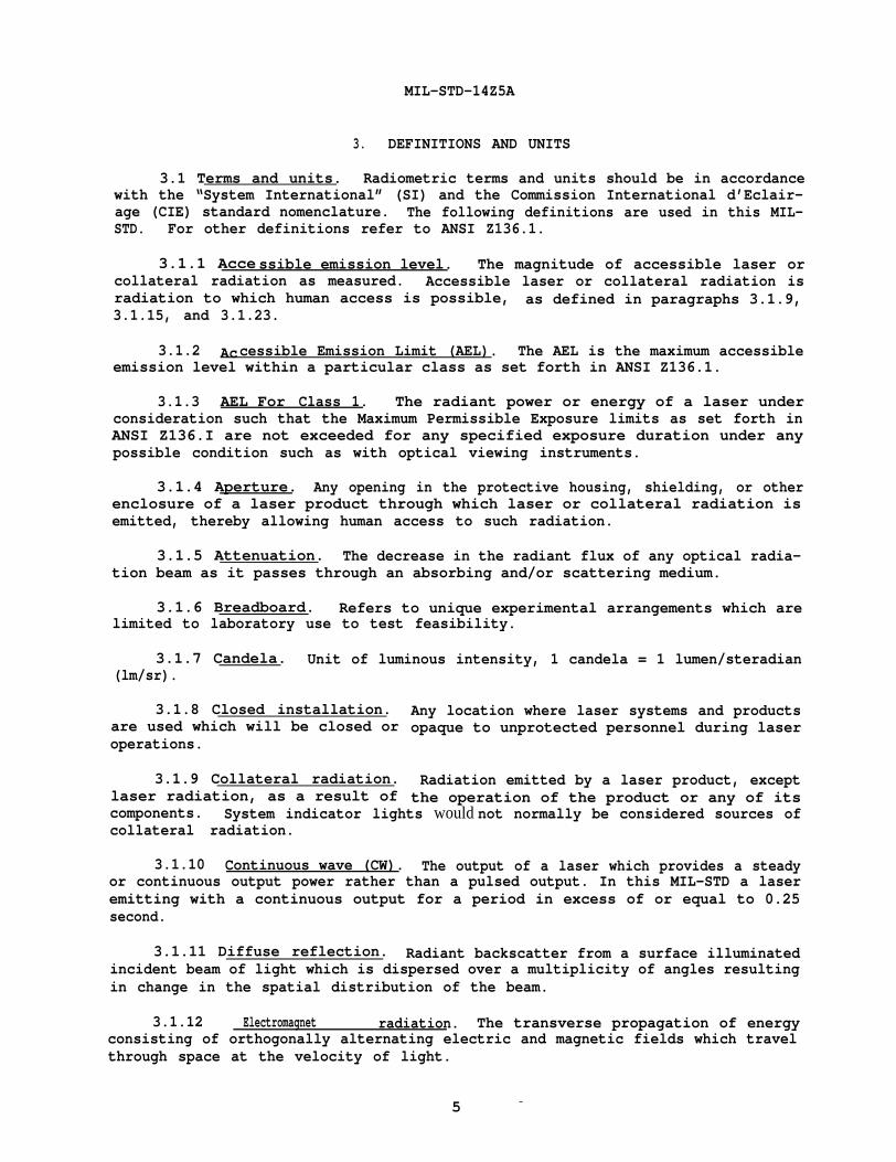
3. DEFINITIONS AND UNITS
3.1 Terms and units. Radiometric terms and units should be in accordance with the “System International” (SI) and the Commission International d’Eclairage (CIE) standard nomenclature. The following definitions are used in this MILSTD. For other definitions refer to ANSI Z136.1.
3.1.1 Acce ssible emission level. The magnitude of accessible laser or collateral radiation as measured. Accessible laser or collateral radiation is radiation to which human access is possible, as defined in paragraphs 3.1.9, 3.1.15, and 3.1.23.
3.1.2 Accessible Emission Limit (AEL). The AEL is the maximum accessible emission level within a particular class as set forth in ANSI Z136.1.
3.1.3 AEL For Class 1. The radiant power or energy of a laser under consideration such that the Maximum Permissible Exposure limits as set forth in ANSI Z136.I are not exceeded for any specified exposure duration under any possible condition such as with optical viewing instruments.
3.1.4 Aperture. Any opening in the protective housing, shielding, or other enclosure of a laser product through which laser or collateral radiation is emitted, thereby allowing human access to such radiation.
3.1.5 Attenuation. The decrease in the radiant flux of any optical radiation beam as it passes through an absorbing and/or scattering medium.
3.1.6 Breadboard. Refers to unique experimental arrangements which arelimited to laboratory use to test feasibility.
3.1.7 Candela. Unit of luminous intensity, 1 candela = 1 lumen/steradian (lm/sr).
3.1.8 Closed installation. Any location where laser systems and productsare used which will be closed or opaque to unprotected personnel during laser operations.
3.1.9 Collateral radiation. Radiation emitted by a laser product, except laser radiation, as a result of the operation of the product or any of its components. System indicator lights would not normally be considered sources of collateral radiation.
3.1.10 Continuous wave (CW). The output of a laser which provides a steadyor continuous output power rather than a pulsed output. In this MIL-STD a laser emitting with a continuous output for a period in excess of or equal to 0.25 second.
3.1.11 Diffuse reflection. Radiant backscatter from a surface illuminated incident beam of light which is dispersed over a multiplicity of angles resulting in change in the spatial distribution of the beam.
3.1.12 Electromagnet radiation. The transverse propagation of energyconsisting of orthogonally alternating electric and magnetic fields which travel through space at the velocity of light.
5 -

MIL-STD-1425A
3.1.13 Exempted lasers. Military lasers exempted under 76EL-01 DOD from 21 CFR 1040 where compliance would hinder mission fulfillment during actual combat or combat training operations or when the laser product is classified in the interest of national security.
3.1.14 Footcandle (ft cd). A British unit of illuminance of a surface 1 square foot in area from a source of uniformly distributed flux of 1 lumen. One lumen per square foot is a footcandle. This is an obsolete term; see lUX and luminance of a source.
3.1.15 Human access. Access at a particular point to: laser or collateral radiation by any part of the human body, or laser radiation by a straight unobstructed path of up to 100 centimeters from any part of the human body.
3.1.16 Infrared radiation (IR). Electromagnetic radiation with wavelengths This region is often broken
into three spectral bands by wavelength: IR-A is sometimes called near-infrared.
3.1.17 Irradiance (E). The ratio of the radiant power incident upon a surface to the unit area of the surf ce for some element of the surface; its unit
3.1.18 Joule (J). A unit of energy used normally in describing a single pulsed output of a laser, it is equal to 1 watt-second or 0.239 calories (cal).
3.1.19 Lambertian surface. An ideal diffuse surface whose emitted or reflected radiance (or brightness) is independent of the viewing angle.
3.1.20 Laser. Any device which can produce or amplify optical radiation primarily by the process of controlled stimulated emission. A laser may emit electromagnetic radiation from the ultraviolet portion of the spectrum through the infrared portion. Also, an acronym for: Light Amplification by Stimulated Emission of Radiation.
3.1.21 Laser energy source. Any device intended for use in conjunction with a laser to supply energy for the operation of the laser. General energy sources such as electrical supply mains or batteries shall not be considered to constitute laser energy sources.
3.1.22 Laser product. Any manufactured product or assemblage of components which constitutes, incorporates, or is intended to incorporate a laser or laser system. A laser or laser system which is intended for use as a component of an electronic product shall itself be considered a laser product.
3.1.23 Laser radiation. All electromagnetic radiation emitted by a laser product within the spectral range specified in paragraph 3.1.38 and is produced as a result of controlled stimulated emission.
3.1.24 Laser system. A laser in combination with an appropriate laser energy source with or without additional incorporated components. With respect to a weapons system, the terminology “laser subsystem” should be construed to have the same meaning.
6 -

MIL-STD-1425A
3.1.25 Laser controlled area. Any area which contains one or more lasers where the activity of personnel is subject to control and supervision for the purpose of protection from radiation hazards associated with laser operation.
3.1.26 Light. See visible radiation (in paragraph 3.1.56).
3.1.27 Luminous flux. Quantity derived from radiant flux in units of lumens by evaluating the radiation according to photopic vision for a CIE standard photometric observer.
3.1.28 Lumen (lm)-. The derived S1 unit of luminous flux emitted in a solid angle of 1 steradian by a uniform source of luminous intensity of 1 candle. One lumen equals one candle steradian (1 lm = 1 cd.sr).
3.1.29 Luminous transmittance. Ratio of the transmitted luminous flux to the incident luminous flux.
3.1.30 Lux (lx). SI unit of illuminance (illumination) of a surface of 1 square meter in area from a source of uniformly distributed luminous flux of
3.1.31 Maintenance. Performance of those adjustments or procedures specified in user information provided by the manufacturer with the laser product which are to be performed by the user for the purpose of assuring the intended performance of the product. It does not include operation or service as defined in this section. This definition is equivalent to the DOD concepts of operator-performed maintenance and/or organizational maintenance.
Formerly termed “micron,” a measure of length equal to 10 m.
3.1.33 Maximum Permissible Exposure (MPE). Laser radiation exposure levels published in ANSI 2136.1 and established for the protection of personnel. These are levels of laser radiation to which a person may be exposed without known hazardous effects or adverse biological changes in the eye or skin. The MPE’s contained in ANSI 2136.1 are used in this MIL-STD and agree with STANAG 3606.
3.1.34 Nanometer (rim). Unit of length equal to 10-9 meter.
3.1.35 Nominal Ocular Hazard Distance (NOHD). The distance along the axis of the beam from the laser to the possible location of a human eye beyond which the irradiance (W/cm2) or radiant exposure (J/cm ) averaged over the appropriate circular aperture would not be expected to exceed the appropriate MPE.
3.1.36 Operation. The use of the laser product over the full range of its intended functions. It does not include “maintenance or service” as defined in this section. This definition applies to both the FDA Standards and DOD “concepts of operation.”
3.1.37 Optical density (OD). The following logarithmic expression for the attenuation produced by a filter such as an eye protection filter:
OD =
7

MIL-STD-1425A
where 10 is the power incident upon the filter and it is the power transmitted through the filter at a specific wavelength.
3.1.38 Op tical radiation. Electromagnetic radiation with wavelengths which This radiation is often broken into
three spectral regions by wavelength: ultraviolet radiation (200-400 rim), visible radiation (400 - 700 rim), and infrared radiation (700 nm - 1 mm).
3.1.39 Pulse duration. The time increment measured between the half-peakpower points on the leading and trailing edges of a pulse.
3.1.40 Pulsed laser. A laser that delivers its energy in discontinuous bursts i.e., there are time gaps during which no energy is emitted. For the purposes of this MIL-STD a laser which emits for less than 0.25 s.
3.1.41 Radian (rad). A unit of angular measure equal to the angle subtended at the center of a circle by an arc whose length is equal to the radius of the circle.
= 360 degrees one radian = 57.3 degrees
3.1.42 Radiance (L). Radiant power per unit area of a radiating surface per unit solid angle of emission expressed as W/(cm2.sr); radiometric equivalent of brightness.
3.1.43 Radiant energy (Q). Energy in the form of electromagnetic waves usually expressed in units of joules. Commonly used to describe the output of pulsed lasers.
3.1.44 Radiant exposure (H). The radiant energy per unit area incident upon a given surface. It is used to express exposure dose to pulsed laser?radiation and is commonly expressed in J/cm2 or J/(cm .pulse).
The time rate of flow of radiant energy given in units of watts. Commonly used to describe the output power of CW lasers or the average output power of repetitively-pulsed lasers.
3.1.46 Radiant intensity (I). Radiant power in a given direction - radiant flux emitted from the source per unit solid angle (steradian), in the direction of propagation, usually expressed in W/sr.
The ratio of total reflected radiant flux to total incident radiant flux.
3.1.48 Repetitively pulsed laser. A pulsed laser with a sequentially reoccurring pulsed output.
3.1.49 Service. The performance of those procedures or adjustments described in the manufacturer’s service instructions which may affect any aspect of the product’s performance for which this MIL-STD has applicable requirements. It does not include maintenance or operation as defined in this section. This definition is equivalent to DOD concepts of maintenance above the organizational level .
8 -

MIL-STD-1425A
The ratio of the area on the surface of a sphere to the square of the radius of that sphere. It is expressed in steradians (sr).
3.1.51 Specular reflection. A mirrorlike reflection at the wavelength(s) of the incident radiation.
3.1.52 Steradian (srl. The unit of measure for a solid angle. There are
3.1.53 Support equipmnent. Devices or enclosures procured specifically for, or modified for, laser test, calibration, maintenance or other support not part of the laser primary mission.
3.1.54 Transmittance The ratio of total transmitted radiant power to total incident radiant power.
3.1.55 Ultraviolet radiation. Electromagnetic radiation with wavelengths . between soft x-rays and visible radiation. This region is often broken down into three spectral bands by wavelength: UV-A (315-400 rim), UV-B (280-315 nm), and, .UV-C (200-280 rim).
3.1.56 Visible rad iation (liqht). Electromagnetic radiation which can be detected by the human eye. It is commonly used to describe wavelengths which lie in the range between 400 nm and 700 nm. [Note: The CIE visible radiation band extends from 400 to 760 nm differing from this ANSI 2136.1 definition].
3.1.57 Watt (W). The unit of power or radiant flux equal to one joule-persecond. It is used principally with CW lasers.
The distance between two points in a periodic wave which have the same phase is termed one wavelength. The velocity of light (3 x?10° cm/see) divided by frequency (in Hz) equals wavelength (in cm).
9

MIL-STD-1425A
4. DESIGN REQUIREMENTS FOR EXEMPTED LASERS
4.1 Introduction. All laser systems shall be grouped into one of four general hazard classes which indicate the level of control required to minimize personnel injury potential based solely on laser accessible emission levels. Exempted lasers shall be classified from a hazard potential in accordance with the ANSI 2136.1 laser hazard classification system. This classification shall be used in selecting the applicable FDA design requirements which do not restrict operational requirements, e.g., a Class 3a laser (ANSI) should apply the requirements for Class IIIa laser (21 CFR). Additional design requirements are levied by this MIL-STD in the following paragraphs.
4.2 General requirements.
4.2.1 Identification label. Every laser product shall be provided with a tag or label permanently affixed to the device housing so that it is readily accessible to view. Such a tag or label shall contain the full name and address of the manufacturer, the laser model, and the place, month, and year of manufacture. These may not be expressed in code.
4.2.2 Exemption label. In lieu of the certification label required by 21 CFR 1010.2, every laser product exempted under 76EL-01 DOD shall be provided with a tag or label permanently affixed to the device housing so that it is readily accessible to view. The label shall contain the following statement:
CAUTION
This electronic product has been exempted from FDA radiation safety performance standards prescribed in Title 21, Code of Federal Regulations, Chapter I, Subchapter J, pursuant to Exemption No. 76EL-01 DOD issued on 26 July 1976. This product should not be used without adequate protective devices or procedures.
4.2.3 Location of controls. Each laser product shall have operational and adjustment controls located so that human exposure to laser radiation in excess of the appropriate MPE is unnecessary for the operation or adjustment of such controls.
4.2.4 Unintentional output. Laser product design features shall preclude unintentional laser output (e.g. spontaneous firing).
4.2.5 Extraneous radiation and beam irregularities. All lasers and associated optics will be designed so that external secondary beams are not generated unless necessary for the performance of the intended function(s). focused beams, hot spots and collateral radiation will be minimized. Laser systems which employ frequency shifting or harmonic multipliers to alter the fundamental output wavelength shall reduce unnecessary emissions to below the MPE.
4.2.6 Unwanted modes. The laser system shall be designed to preclude unintentional self-oscillation, mode-locking, double-pulsing, or unwanted modes, when practicable. If these modes cannot be eliminated, the laser will be classified as per the worst possible accessible emission level.

MIL-STD-1425A
4.2.7 Interlocks. Interlocked protective housings shall be provided to protect personnel from high voltage sources and unnecessary laser and collateral radiation in excess of the AELs. Aural or visual indication of interlock defeat shall be provided. Interlocks shall return to their normal operation when the access cover door is returned. When laser radiation exceeding the ANSI AEL for Class 1 is accessible, visual indicators will be readily visible while wearing suitable laser protective eyewear.
4.2.8 Optical ports. Viewing ports and display screens which allow the operator to view laser radiation shall attenuate the laser radiation to limit personnel exposure to below the appropriate MPE.
4.2.9 Optical sightS. Laser product pointing or viewing optics with a magnifying power exceeding 1.0 shall include a built-in laser safety filter within the optical train which protects the operator from reflections from specular surfaces or exposure from force-on-force training. Such filters should not significantly impair visibility and shall be permanently attached or designed so that the optical train cannot be assembled without the filter. The laser system or individual sight shall be marked to indicate the level and type of protection afforded in the viewing optics either by 00 and wavelength or by the use of a Filter Marking Code consisting of a single-letter laser safety code on the first line and an individual filter code on the second line consisting of a two-letter design code, a five-digit manufacturing code and a five digit lot number. Minimum ODs for the single-letter laser safety codes for both magnifying and non-magnifying direct-view optics are provided in Tables 2 and 3, respectively. These codes may not fully describe the level of laser protection in the sight.
TABLE 2. Minimum Optical Densities Values for Optical Sight Categories for Magnifyinq Optical Sights.
Safety Category 694.3 nm 800-950 nm 1050-1065 nm
A 5.0 5.0 5.0 B 5.0 2.0 5.0 c 5.0 1.0 5.0 D 5.0 0.3 5.0 E 4.0 2.0 5.0 F 3.0 2.0 5.0 G 2.0 2.0 5.0 H 1.0 1.0 5.0 I 0.4 1.5 4.5 J 0.3 1.0 3.0 K 0.7 2.0 5.0 L -- 0.3 5.0 M 2.0 2.0 2.0 N 1.0 1.0 1.0 0 -- -- --P 3.0 3.0 3.0
NOTE : The OD values given above are for the entire system. For example, a 4.5 density filter installed in a sight with an intrinsic filtration density of 0.6 would result in an 00 of 5.1.
11

MIL-STD-1425A
TABLE 3. Minimum Optical Densities Values for Optical Sight Categories for Non-Magnifying Optical Sights.
Safety Category 694.3 nm 800-950 nm 1050-1065 nm
A 3.5 3.5 3.5 B 3.5 0.5 3.5 c 3.5 -- 3.5 D 3.5 -- 3.5 E 2.5 0.5 3.5 F 1.5 0.5 3.5 G 0.5 0.5 3.5 H -- -- 3.5 I -- -- 3.0 J -- -- 1.5 K -- 0.5 3.5 L -- -- 3.5 M 0.5 0.5 0.5 N --
------
----o
P 1.5 1.5 1.5
NOTE : The OD values given above are for the entire system.I
4.2.10 Associated hazards. Electronic systems shall be designed in accordance with MIL-STD-454. Other hazards associated with the laser and its operation shall be controlled by engineering in accordance with MIL-STD 882. Paragraph A.2.2, Appendix A herein, lists some additional hazards which must be considered.
4.2.11 Laser warning labels. Laser warning labels for exempted lasers shall provide clear instructions to the operators, maintainers and potential bystanders to preclude laser injury. Warning labels developed for industrial and laboratory environments may lead to confusion when read by personnel using lasers in an outdoor environment. Section 4.3 contains further details pertaining to these military labels.
4.3 Class 1. Class 2, Class 2a and Class 3a Laser Requirements.
4.3.1 Design requirements. Lasers classified as ANSI Class 1, Class 2, Class 2a, or Class 3a will meet the design (performance) requirements of 21 CFR Class I, Class II, Class IIa or Class IIIa respectively except where such requirements restrict operational capability or security.
4.3.2 Labeling requirements. Lasers classified as ANSI Class 1, Class 2, Class 2a, or Class 3a will meet the designation and warning requirements of 21 CFR Class I, Class II, Class IIa, or Class IIIa, respectively with the exception that the ANSI classification will be displayed in the lower right corner rather than the FDA class, e.g., “ANSI Class 2 Laser Product. ” Labels shall be permanently affixed or inscribed on such products as to be legible and readily accessible to view when the product is fully assembled for use. The warning labelshall be affixed to the laser system housing near the beam exit port and/or fire
12

MIL-STD-1425A
button when possible in such a manner that viewing the label does not require personnel exposure to laser radiation. The information labeling is changed from 21 CFR as illustrated in Figures la, lb and lc. Numerical output information, such as wavelength(s) and maximum power output (when unclassified), shall be located along the lower edge in a smaller font. The word “INVISIBLE” or ‘VISIBLE,” as appropriate, shall precede the word “RADIATION. ” Other labeling requirements of the FDA Standard shall be applied unchanged except as noted in the following paragraphs.
4.3.2.1 Label colors. When camouflage may be compromised by labels, muted colors appropriate to the camouflage paint scheme may be used.
4.3.2.2 Classified. Information classified in the interest of national security shall not be divulged on any label.
4.3.2.3 Class 1 label. If a Class 1 laser has a defeatable interlock which when defeated allows access to Class 3b or Class 4 emission levels then an additional label shall be installed on or near the access panel which reads:
DANGER
Laser Radiation When Open and Interlock Defeated, Avoid Eye or Skin Exposure to Direct or Scattered Radiation.
4.3.2.4 Class 2a label. All Class 2a (as defined by ANSI Z136.1) exempted lasers shall have affixed a label bearing the following wording: ‘ANSI Class 2a Laser Product-Avoid Long-Term Viewing of Direct Laser Radiation.” This label need not bear the laser warning symbol (starburst) or signal word (CAUTION), but must be visible during laser operation.
4.3.2.5 Alternate labeling. Nonexempted lasers may incorporate military labeling when alternate labeling has been requested by the manufacturer and approved as a variance by FDA in accordance with 21 CFR 1040 (g)(lO).
4.4 Class 3b and Class 4 Laser Requirements.
4.4.1 Warning labels. Class 3b and Class 4 lasersas defined by ANSI shall be provided with a label similar to the examples illustrated in Figures 2a and 2b. Such labels shall be permanently affixed or inscribed on such products to be legible and readily accessible to view when the product is fully assembled for use. The label shall be affixed to the laser system housing near the fire button and exit port when the port is remote from the operator in such a manner that viewing the label does not require personnel exposure to laser radiation. The label shall use the word “DANGER” and include the type of laser and the word “VISIBLE” or “INVISIBLE” as appropriate shall precede the word “RADIATION.” The label shall also contain inappropriate instructional safety statement or control message for the operator or bystander as applicable. For example, the operator warning for Class 3b and Class 4 ground target designators should read “DO NOT
13

MIL-STD-1425A
14

MIL-STD-1425A
15

MIL-STD-1425A
AIM AT PERSONNEL OR FLAT GLASS SURFACES OR TARGETS WITHIN 10 METERS. ” The bystander warning for visible and near-infrared (400-1400 nm) Class 3b and Class 4 lasers should read “DO NOT LOOK INTO PORTHOLE” and for infrared (1,400 nm - 1 nm) and ultraviolet (200-400 nm) Class 3b and Class 4 lasers, “DO NOT EXPOSE EYE OR SKIN TO DIRECT OR SPECULARLY REFLECTED BEAMS.” The “DANGER” labels shall be printed upon a white background with a bright red oval around the word ‘DANGER” and shall contain a red “starburst” and black lettering. When camouflage may be compromised by such warning labels, muted colors (i.e., olive drab) shall be used. The ANSI laser hazard classification, wavelength(s) and maximum radiant power or energy shall be added along the lower edge of the label if this information is not classified in the interest of national defense.
4.4.2 Unintentional output. No single operator error or materiel failure shall cause unintentional laser output that exceeds the ANSI AEL for Class 1. At least two operator actions will be required to cause the laser to function. One of these shall serve as a laser arming control. No laser output shall be possible when this control is-in the safe position. Power control switches may serve as laser arming controls. Master key controls will be required only when specified by the procuring activity.
4.4.3 Laser fire switch. The laser fire trigger or switch shall be clearly identified and shall be physically protected to prevent accidental activation. When possible, the switch shall be a guarded positive action (“dead-man”) type requiring continuous operator intent to operate the laser button. Laser activation circuitry for pulsed lasers shall be of a fail-safe design so that continual depression or short circuiting of the fire control switch will not cause repeated emissions unless necessary for performance of intended function(s). When operational considerations preclude the use of a deadman switch, a toggled switch may be used, providing that adequate design safeguards are provided to prevent long-term inadvertent lasing, e.g., through watch-dog timers and system logic switching.
4.4.4 Exit-port cover. An exit-port cover shall be provided which is permanently installed within the laser product or attached to the device housing and which is capable of preventing access by any part of the body to all laser radiation in excess of the ANSI AEL for Class 1. An example of such a device is a swivel beam stop which can be latched over the laser output port, or a threaded attenuating cap with chain. Rotation of the laser to an enclosed stowed position is also acceptable. The cover chosen shall clearly indicate when it is in place (SAFE) or open and shall not be damaged by repeated laser firings when it is in either position.
4.4.5 Remote control connector. A readily available remote control interlock capability shall be incorporated on laser products (or alternatively on auxiliary power supply systems for laser products) which can be used during maintenance or service to interlock the system via an electrical cable to entrance door switches of a laser maintenance or service area. The connector shall have an electrical potential difference of no greater than 130 root-mean-square volts between the terminals of the remote control connector. This requirement is not essential if the laser is always directed into an interlocked test set enclosure for maintenance or service procedures. When the terminals of the connector are not electrically joined, human access to all laser radiation and collateral radiation in excess of applicable exposure limits in excess of ANSI
16

MIL-STD-1425A
AEL for Class 1 shall be prevented. once disconnected, the system shall not automatically reactivate without an intentional reset.
4.4.6 Boresiqht. Boresight alignment and retention shall be designed consistent with system mission requirements and shall be considered a safety critical item.
4.4.7 Emission indicator. Laser status (emission) indicators shall be provided to inform the laser operator when the laser is prepared to fire (armed) and when the laser is actually emitting optical radiation (firing). Indicators shall be aural or visual (tone or light), or as specified by the procuring agency and shall not compromise camouflage. If visual indication is selected, the source shall be visible under daylight as well as nighttime conditions and also when viewing through laser protective eyewear designed specifically for the wavelength(s) of the emitted laser radiation if such eyewear is required to be worn during operation, maintenance or service. Visual indicators shall be located so that viewing does not require personnel exposure to laser radiation in excess of the ANSI AEL for Class 1. A light could differentiate between “armed” and “firing” states by emitting either a continuous or blinking display. The display could be a part of the sight reticle or its outer ring. When armed and firing are differentiated by a continuous tone or light and an intermittent tone or blinking light, the continuous tone or light shall mean “armed” and the intermittent tone or blinking light shall mean “firing.”
4.4.8 Airborne lasers. Laser systems installed on aircraft shall be designed to prevent laser output while the aircraft is not airborne. However, a defeating switch, protected from inadvertent activation, may be provided to override the ground interlock to aid ground operation, maintenance or service.
4.4.9 Beam pointinq. Laser product design features shall incorporate controls to optimize positive operator control of beam pointing. This shall include a means of ensuring boresight retention and software systems safety. For systems with automatic target tracking capability, an automatic disable capacity shall be incorporated to inhibit laser firing if target tracking outside the system specifications occurs or when the laser sight line reaches the gimbal limits or the system mask limit. At least two independent systems shall be capable of disabling the laser if no hardware stops are installed. A provision to override these automatic features during combat is permitted.
4.4.10 Scanninq beams. Laser products that use a beam scanning technique shall include a feature which terminates or reduces the beam output to ANSI AEL for Class 1 immediately upon the cessation of scanning or upon scanning pattern irregularities such as a change in either scan velocity or amplitude. This requirement applies if such irregularities are not normal to the operation of the laser product and also if the unintended pattern changes would increase the hazard potential of the laser product.
4.4.11 Traininq mode. When a training mode for the laser is required by the contract, provisions will be made to reduce the hazardous emissions to the lowest level consistent with training requirements. This may be accomplished through the use of a beam attenuator, beam expander or diffuser on the laser. Alternately, separate systems such as less hazardous lasers, TV cameras, etc. may be used to meet this requirement. When the laser can be used in both a mission
.

MIL-STD-1425A
and training mode, a visual indication shall be provided to inform the operator and outside observers that the laser is positively in the training mode.
4.4.12 Very hiqh power lasers. Laser systems which can emit very high CW radiant power or very high radiant energy pulses may require specific safety features unique to the device and, therefore, require further consideration.
4.4.13 Determination of NOHD. An estimated value of NOHD may be calculated using the appropriate laser system output parameters with regard to the environmental conditions under which the laser is to be employed. While contractor determination of NOHD may be used during system design, final NOHD must be certified by the Government based upon test prior to Government personnel exposure.
4.4.14 Optical sights. Aiming optics shall employ a reticle that can be viewed under any illumination condition for which the laser is designed. The reticle shall not impair any dark adaptation of the observer’s eye. Calibrated retitles should be considered so that the laser operator can determine the proximity of the laser beam to target buffer zones.
18

MIL-STD-1425A
5. DESIGN REQUIREMENTS FOR ASSOCIATED SUPPORT EQUIPMENT
5.1 Introduction. Support equipment includes test equipment, fixtures, and other enclosures procured to support laser systems. Design considerations for laser facilities are contained in Appendix A. Support equipment shall be designed to meet the following requirements based upon the hazard classification as defined by ANSI Z136.1 of the laser(s) to be used with such equipment. The support equipment in conjunction with the laser system shall meet the requirements of paragraph 4 of this MIL-STD and shall be considered nonmilitary exempt under 76 EL-01 DOD unless this equipment is used solely in support of exempted lasers.
5.2 General requirements.
5.2. 1 Design goal. Design of associated support equipment shall insure that laser radiation emitted duri ng maintenance or service is no greater than the ANSI AEL for Class 1 and collateral radiation is not in excess of applicable limits, when practicable. Such equipment should confine the laser radiation within an opaque enclosure which is adequately interlocked to prevent levels in excess of the ANSI AEL for Class 1 when the enclosure is removed. Such an enclosure shall be provided with appropriate exterior warning indicators and labels. Enclosed equipment can eliminate the need for specialized facilities.
5.2.2 Associated hazards. Other associated hazards from the support equipment, and the operation, maintenance or service of the laser shall be controlled by suitable engineering in accordance with MIL-STD 882. Adequate instructional to safe techniques and personnel protective means shall be included in all technical references (manuals) and plainly marked on the laser product when potentially hazardous areas are accessible.
5.3 Requirements for Class 1, Class 2, Class 2a. and Class 3a Laser Support Equipment. Support equipment which is classified as Class 1, Class 2, Class 2a, or Class 3a shall meet the requirements of paragraph 4.3.
5.4 Requirements for Class 3b and Class 4 Laser Support Equipment.
5.4.1 Test equipment. Laser system test equipment for boresight and laser performance testing shall enclose or attenuate the beam to limit personnel exposure to below the AEL for ANSI Class 1 and shall be interlocked to the laser to prevent inadvertent laser operation outside the enclosure if the test equipment is not used in a closed installation.
5.4.2 Interlock switch. A safety (access) interlock switch shall interface with ANSI Class 3b and Class 4 laser systems under test such that inadvertent removal of test sets or poor connection will terminate or limit the laser output to the ANSI AEL for Class 1, or to the ANSI AEL for Class 2, if applicable.
5.4.3 Warninq system. A warning system (e.g., flashing light, audible indicator or other physical indicator external to the test set) will be activated immediately prior to operation of the laser and will remain activated until the laser output has been reduced to the ANSI AEL for Class 1 or to the ANSI AEL for Class 2, if applicable, The warning system shall be designed not to attract personnel attention in such a manner as to create a potential hazard.
19

MIL-STD-1425A
5.4.4 Operation switch. All equipment used as support equipment for laser hardware which could directly activate the laser preferably should incorporate a positive action (“dead-man”) switch which must be activated when laser firing is- desired. When a dead-man switch is not incorporated, an emergency cut-off switch shall be provided which allows emergency cut-off of laser output in excess of the ANSI AEL for Class 1 or Class 2, as appropriate. This switch shall be readily accessible from the operator’s position and shall permit one-step operation. ‘Normal power or control switches may fulfill this function. (see paragraph 4.4.3).
5.4.5 Master switch. A key-lock master switch shall be required to prevent unauthorized activation of any test facility component used to supply power directly to the laser that is necessary for its operation.
5.4.6 Be am stops. The laser beam shall be terminated by a beam stop which is diffuse (nearly a Lambertian surface) having a low value of reflectance at the laser wavelength (s). Where possible, such a beam stop shall also be fire resistant and unable to emit toxic or carcinogenic fumes when exposed to the laser (s) for which the beam stop has been designed. The beam stop shall be marked for the type(s) and power level(s) for which it is procured. Firebrick, certain ceramics and graphite are examples of backstops for high power infrared lasers. However, certain firebrick may contain beryllium compounds, which can produce hazardous beryllium fumes. Where toxic gases cannot be prevented, appropriate control measures for the protection of personnel, such as appropriate exhaust ventilation, shall be engineered into the system. If exhaust ventilation is a required safety feature, the ventilation system shall be interlocked to prevent operation of the laser without the ventilation system operating.
20

MIL-STD-1425A
6. NOTES
6.1 Intended use. Lasers conforming to this standard are designed expressly for combat or combat training operations or are classified in the interest of national security. This standard is used in lieu of the federal standard on lasers (21 CFR 1040.10) when the military exemption (76 EL-01 DOD) is used. In addition, design requirements are provided for associated laser support equipment.
.6.2 Subject term (key word) listing.
Design requirements Laser Laser acquisition Laser design Laser eye protection Laser facility design Laser safety Laser safety design Laser support equipment Laser systems Maintenance Military lasers Protective equipment
6.3 Changes from previous issue. Asterisks or vert cal lines are not used in this revision to identify changes with respect to the previous issue due to the extensiveness of the changes.

MIL-STD-1425A
APPENDIX A
LASER FACILITY DESIGN
A.1 Introduction. Design requirements for laser facilities shall follow requirements given in specific component laser standards, e.g., AFOSH Std 161-10. Where specific component standards do not exit, this Appendix contains basic requirements which should be met. Laser facilities include specialized vans, bays and other work area enclosures procured to support laser systems. Laser facilities should be designed to meet the following requirements based upon the hazard classification as defined by ANSI 2136.1 of the laser(s) to be used with such facilities. Laser facilities equipment in conjunction with the laser system shall meet the requirements of paragraph 4 of this MIL-STD and shall be considered nonmilitary exempt under 76 EL-01 DOD unless this equipment is used solely to support of exempted laser products.
A.2 General requirements.
A.2.1 Auxiliary equipment. Design of associated support equipment shall insure that laser radiation emitted during maintenance or service is no greater than the ANSI AEL for Class 1, and collateral radiation is not in excess of applicable limits when practicable. Such equipment shall confine the laser radiation within an enclosure which is adequately interlocked to prevent levels in excess of the ANSI AEL for Class 1 when the enclosure is removed. Such an enclosure shall be provided with appropriate exterior warning indicators and labels.
A.2.2 Associated hazards. Other associated hazards from the support equipment, and the operation, maintenance or service of the laser shall be controlled by suitable engineering in accordance with MIL-STD 882. Adequate instruction as to safe techniques and personnel protective means shall be included in all technical references (manuals) and plainly marked on the laser product when potentially hazardous areas are accessible. Below is a partial listing of some potentially hazardous areas to be considered. See MIL-STD-454 for electronic systems and ANSI Z136.1 for reference documents on associated hazards.
Electrical
High voltages/amperages Arcing Capacitor charge/discharge Transformer and pulse forming networks Grounding Short circuits
Pressurized Systems
Storage tanks Manifolds Piping Regulators Safety burst discs Seals Bleed and purge systems
. 22
MIL-STD-1425A
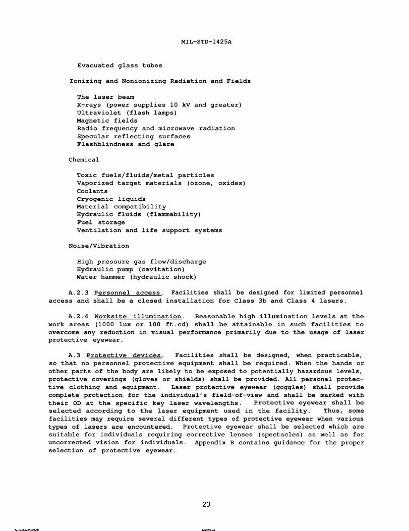
Evacuated glass tubes
Ionizing and Nonionizing Radiation and Fields
The laser beam X-rays (power supplies 10 kV and greater) Ultraviolet (flash lamps) Magnetic fields Radio frequency and microwave radiation Specular reflecting surfaces Flashblindness and glare
Chemical
Toxic fuels/fluids/metal particles Vaporized target materials (ozone, oxides) Coolants Cryogenic liquids Material compatibility Hydraulic fluids (flammability) Fuel storage Ventilation and life support systems
Noise/Vibration
High pressure gas flow/discharge Hydraulic pump (cavitation) Water hammer (hydraulic shock)
A.2.3 Personnel access. Facilities shall be designed for limited personnel access and shall be a closed installation for Class 3b and Class 4 lasers.
A.2.4 Worksite illumination. Reasonable high illumination levels at the work areas (1000 lux or 100 ft.cd) shall be attainable in such facilities to overcome any reduction in visual performance primarily due to the usage of laser protective eyewear.
A.3 Protective devices. Facilities shall be designed, when practicable, so that no personnel protective equipment shall be required. When the hands or other parts of the body are likely to be exposed to potentially hazardous levels, protective coverings (gloves or shields) shall be provided. All personal protective clothing and equipment. Laser protective eyewear (goggles) shall provide complete protection for the individual’s field-of-view and shall be marked with their OD at the specific key laser wavelengths. Protective eyewear shall be selected according to the laser equipment used in the facility. Thus, some facilities may require several different types of protective eyewear when various types of lasers are encountered. Protective eyewear shall be selected which are suitable for individuals requiring corrective lenses (spectacles) as well as for uncorrected vision for individuals. Appendix B contains guidance for the proper selection of protective eyewear.

MIL-STD-1425A
A.4 Class 3b and Class 4 Laser Facility Requirements.
A.4.1 Warning sign. A laser warning sign shall be displayed on all entry points or doors to the facility. Warning signs shall use the word “DANGER” and include the type of the laser, the word “VISIBLE,” and/or “INVISIBLE,” as appropriate, and shall precede the word “RADIATION.” The label shall also contain an appropriate instructional statement such as “KNOCK BEFORE ENTERING” or “AUTHORIZED PERSONNEL ONLY - KNOCK AND WAIT.” When multiple lasers are present the types of lasers may be omitted and only a single warning sign is necessary. Color information for these warning signs is given in paragraph 4.4.1. Additional design specifications for accident prevention signs are contained in ANSI Z35.1. Examples of laser warning signs are illustrated in Figure A-1. A laser range warning sign, Stock No. 0177-LF-OO-0500 is available from Naval Publications and Forms Center (Code 1062), 5801 Tabor Avenue, Philadelphia, PA 191205099. Order sign on DD Form 1348 and provide cost accounting data.
A.4.2 Interlock switch. A safety (access) interlock switch shall interface with ANSI Class 3b and Class 4 laser systems under test such that inadvertent removal or poor connection of test sets will terminate or limit the laser output to the ANSI AEL for Class 1, or to the ANSI AEL for Class 2, if applicable.
A.4.3 Warning system. A warning system (e.g., bell and/or flashing light or other visible indicator external to the test set) will be activated immediately prior to operation of the laser and will remain activated until the laser output has been reduced to the ANSI AEL for Class 1 or to the ANSI AEL for Class 2, if applicable.
A.4.4 Operation switch. All equipment used as support equipment for laser hardware which could directly activate the laser incorporate a positive action (“dead-man”) switch which must be activated when laser firing is desired. When a dead-man switch is not incorporated, an emergency cut-off switch shall be provided which allows emergency cut-off of laser output in excess of the ANSI AEL for Class 1 or Class 2, as appropriate. This switch shall be readily accessible from the operator’s position and shall permit one-step operation. Normal power or control switches may fulfill this function (see paragraphs 4.4.3 and 5.4.4).
A.4.5 Master switch. A key-lock master switch shall be required to activate any vital test facility component used to supply power directly to the laser that is necessary for its operation.
A.4.6 Test equipment. Laser system test equipment for boresight and laser performance testing shall enclose the beam to limit personnel exposure to below the AEL for ANSI Class 1 and shall be interlocked to the laser to prevent inadvertent laser operation outside the enclosure if the test equipment is not used in a closed installation.
A.4.7 Test fixture. Where the laser is not otherwise supported rigidly, a mechanical fixture shall be provided to rigidly attach the laser in a fixed position during testing and maintenance. The location and orientation of the fixture shall be determined so that exposures of personnel to the direct beam are minimized while also maintaining an efficient environment.

MIL-STD-1425A
25
MIL-STD-1425A
A.4.8 Beam stops. The laser beam shall be terminated by a beam stop which is diffuse (nearly a Lambertian surface) having a low value of reflectance at the laser wavelength(s). Where possible, such a beam stop shall also be fire resistant and unable to emit toxic or carcinogenic fumes when exposed to the laser(s) for which the beam stop has been designed. The beam stop shall be marked for the type(s) and power level(s) or laser(s) for which it is procured. Firebrick, certain ceramics and graphite are examples of backstops for high power infrared lasers. However, certain firebrick may contain beryllium compounds, which can produce hazardous beryllium fumes. Where toxic gases may be emitted, appropriate control measures for the protection of personnel, such as appropriate exhaust ventilation, shall be engineered into the system.
A.4.9 Paint. Interior surfaces of the facility (walls, ceilings, floors) shall be painted with a finish which has a low value of reflectance at the laser wavelength(s) and which will diffuse the laser beam while maintaining an acceptable ambient illumination. Standard wall paints will meet this requirement.
A.4.1O Very high power lasers. Facilities designed for very high power CW or high energy pulsed lasers should have means to enclose the entire beam path within the facility. Such an enclosure should be designed to withstand the direct beam. Laser operations outside the facility require additional safety features such as a warning system to alert all personnel to clear the beam path area, and a prealignment subsystem containing a laser such as a low power laser operating at a visible wavelength. Remote control firing with television monitoring shall be employed when necessary.
26

MIL-STD-1425A
APPENDIX-B
LASER PROTECTIVE EYEWEAR
B.1 Background. The need for laser protective eyewear has been demonstrated for all regions of the optical spectrum. It has been known for some time that visible and near infrared laser wavelengths present a unique hazard to the retina of the eye due to the focusing ability of the lens. Furthermore, the eye is about 100,000 times more vulnerable to injury than the skin in this retinal hazard region, i.e., 400-1400 nm. In spectral areas outside this region, the eye and skin are considered equally vulnerable to injury. However, a severe burn of the cornea may produce a loss of vision after healing, whereas a skin burn may not pose such severe consequences.
B.2 General.
B.2.1 Policy. Laser protective eyewear shall be selected for the worst possible exposure situation. It should allow the best compromise between protection and high visibility to prevent an associated hazard due to reduced vision and be fully compatible with normal corrective lenses (spectacles) when required. Laser protective eyewear is not considered to be a totally reliable safety device since eyewear usage requires conscious effort by an individual. Therefore, eye protection shall be selected when other engineering controls, such as total beam enclosure, are not suitable.
B.2.2 Factors. Several factors determine whether eyewear is necessary and, when necessary, which eyewear is proper for a specific situation. At least three output parameters of the laser must be known: maximum exposure duration, wavelength, and output power (or output irradiance, radiant exposure, or energy)as well as the applicable safe corneal radiant exposure or AEL for Class 1 from ANSI Z136.1. In addition, some knowledge of such environmental factors as ambient lighting and the nature of the laser operation may also be required.
B.2.3 Construction. Laser protective eyewear is presently available commercially in a variety of designs for most laser wavelengths. The eye protection general consists of a filter plate or stack of filter plates, or twofilter lenses which selectively attenuate at specific laser wavelengths, but transmit as much visible radiation as possible. Eyewear is available in several designs. Suitable eyewear to be worn include coverall spectacles with opaque side-shields, coverall spectacles with somewhat transparent side-shields, and laboratory style coverall goggles with flat glass or plastic absorbers.
B.2.4 Ope rational cons iderations. The requirements for protective eyewear vary considerably. This Appendix deals only with protective eyewear when required during service or maintenance. This Appendix should not be used for determining requirements for other types of laser operations. Eyewear is required for unenclosed ANSI Class 4 lasers and where specular reflections fromANSI Class 3 lasers are not controlled. However, where viewing the beam is essential (as in many holography applications and optical alignment procedures), other precautions must be taken to prevent ocular exposure levels above ANSI exposure limits.
B.3 Eyewear selections. The following factors must be taken into consideration before choosing laser safety eyewear:
27 -

MIL-STD-1425A
B.3.1 Step 1 - Determine the Laser Wavelength. The wavelength(s) of laser radiation limit the type of eyewear to those containing filters which greatly reduce or essentially prevent particular wavelength(s) from reaching the eye. It is emphasized that may lasers emit more than one wavelength and that each wavelength must be considered. It is seldom adequate to simply consider the protection at the wavelength corresponding to the greatest output power or energy. For instance, a helium-neon laser may emit 100 mW at 632.8 nm and only 10 mW at 1150 nm, but eyewear which absorb the 632.8 nm wavelength may absorb relatively little or nothing at the 1150 nm wavelength which is also hazardous to the eye. Hence the wavelength range must be clearly marked to indicate the laser wavelength(s) for which the protective eyewear was designed.
B.3.2 Step 2 - Determine Maximum Irradiance (or Radiant Exposure)_. If the beam is never focused and is larger than the diameter of the eye’s pupil, the peak output irradiance or radiant exposure should be the guiding value for use in Table B-1. If the entire beam may enter the pupil of the eye, either through the use of optical instruments which may focus the beam or simply because the laser diameter is less than 7 mm, then the “effective-irradiance” or “effectiveradiant- exposure” can be determined by dividing the output power or energy by20.385 cm for use in Table B-1.
B.3.3 Step 3 -Determine the OD. The OD is a parameter for specifying the attenuation afforded by a given thickness of a filter. Since laser beam intensities may be a factor of a thousand or a million above safe exposure levels, “percent transmission” notation can be unwieldy. For instance, goggles with a transmission of 0.000001 percent can be described as having an OD of 8.0. The OD is a logarithmic notation and is described in the following (mathematical) expression:
OD =
irradiance or radiant exposure of the transmitted beam. Thus, a filter attenuating a beam by a factor of 1000 or 103 has an OD of 3, and attenuating a beam by
The minimal required OD for eyewear filters is determined by the maximum laser beam irradiance or radiant exposure to which the individual could be exposed and the ANSI EL for Class 1. The OD of two highly absorbing filters when stacked is nearly the sum of two individuals OD’S. Table B-1 requires 0D’s (or alternatively dB of attenuation, or attenuation factors) for various laser beam intensities which could be incident upon safety eyewear.
6.3.4 Step 4 - Assess Visible Transmittance of Eyewear. Since the object of laser protective eyewear is to attenuate the laser wavelengths while transmitting as much of the visible light as possible, visible (or luminous) transmittance should be assessed. A low visible transmittance (usually measured in percent) creates problems of eye fatigue and may require an increase in ambient lighting in indoor environments. However, adequate OD at the laser wavelengths shall not be sacrificed for improved luminous transmittance.
B.3.5 Step 5 - Consider Laser Filter Damage Threshold. At very high beam intensities, filter materials which absorb the laser radiation are crazed, cracked, melted or otherwise damaged. Thus, it becomes necessary to consider a damage threshold for the filter. Typical damage thresholds from Q-switched and
28 “

MIL-STD-1425A
29
MIL-STD-1425A
mode-locked pulsed laser radiation fall between 10 and 100 J/cm* for absorbing
occurs to filter and frame materials from 5 and 10 W CW lasers. Intensities from lasers which would cause filter damage are in excess of those which may present a serious skin hazard or fire hazard and, therefore, personnel shall not be permitted in the beam area of such lasers.
B.3.6 Step 6 - Consider Methods of Construction.
B.3.6.1 There are basically two effects which are utilized to selectively attenuate laser wavelengths. filters are designed to make use of selective spectral absorption by colored glass or plastic, or selective reflection from dielectric coatings on glass, or both. Each method has its advantages.
B.3.6.2 The simplest method of fabrication is to use colored glass absorbing filters which are generally the most effective in resisting damage from wear and from very intense laser sources. Unfortunately, most absorbing filters are not case-hardened to provide impact resistance, but clear plastic sheets are generally placed behind the glass filter.
B.3.6.3 The advantage of using reflective coatings is that they can be designed to selectively reflect a given wavelength while transmitting as much of the rest of the visible as possible. However, some angular dependence of the spectral attenuation factor is generally present.
B.3.6.4 The advantages of using absorbing plastic filter materials are greater impact resistance, lighter weight, and ease of molding into curved shapes. The disadvantages are that they are more readily scratched, quality control appears to be more difficult, and the organic dyes used as absorbers are more readily affected by heat and ultraviolet radiation and may saturate or bleach under Q-switched laser irradiation.
B.3.6.5 The advantages of using glass or crystalline filter materials are greater durability in harsh environments such as exposure to low temperatures, dust and sand or chemical solvents.
B.3.6.6 To reduce the reflected beam hazard, protective eyewear with curved lenses should be considered.

MIL-STD-1425A
CONCLUDING MATERIAL
Lead Standardization Activity: Preparing Activity:
Army - EA Army - EA Project No. 4240-0570
Custodians:
Army - EA Navy - SH Air Force -99
Review Activities:
DLA - GS Army - AR, AT, CR, GL MD, TE