Embed Size (px)
Citation preview

ML-KID-1 88-216A20 FEBRUARY 1993
SUPERSEDINGMIISITM88-21616 MARCH 1987
MILITARY STANDARD
INTEROPERABILITY STANDARDSFOR DATA ADAPTER CONTROL MODE
AMSC N/A AREA TCTS
DISTRIBUTION STATEMENT A. Approval for public release; distribution is unlimited.
Downloaded from http://www.everyspec.com
MIL-ST’D-188-216A
FOREWORD
1. Originally, Military Standard 188 (MIL-STD-188) coveredtechnical standards for tactical and long haul communications,but later evolved through revisions (MIL-STD-188A, MIL-ST’D-188B)into a document applicable to tactical communications only(MIL-sm-188c) ●
2. The Defense Information Systems Agency (DISA), formerlyknown as the Defense Communications Agency (DCA) published DCAcirculars (DCACS) promulgating standards and engineeringcriteria applicable to the long haul Defense CommunicationsSystem (DCS) and to the technical support of the NationalMilitary Command System (WCS).
3. As a result of a Joint Chiefs of Staff (JCS) action,standards for all military communications are now being publishedin a MIL-STD-188 series of documents. The MIL-STD-188 series issubdivided into a MIL-STD-188-1OO series covering commonstandards for tactical and long haul communications, aMIL-STD-188-200 series covering standards for tacticalcommunications only, and a MIL-STD-188-300 series coveringstandards for long haul communications only. Emphasis is beingplaced on developing a common standards for tactical and longhaul communications published in the MIL-STD-188-100 series.
4. This document is the result of JCS action requiring that thetechnical characteristics of Data Adapter Control Mode (DAm)procedures previously contained in various specifications beupdated and published in the MIL-S~-188 series of standards.
5. This military standard (MIL-S’ID) is approved and will beused by the Office of the Secretary of Defense, the MilitaryDepartments, the chairman of the Joint chiefs of Staff and theJoint Staff, the Unified and Specified Commands, The DefenseAgencies, and DoD Field Activities.
6. The DACM was previously described in Joint TacticalCommunications Office (JTCO) document TT-A3-9013-0048B andMIL-STD-188-216.
7. This document supersedes paragraphs 3.2.2 through3.2.4,3.2.5, and 3.2.6, and Appendix I of the JTCO specificationTT-A3-9013-0048B.
Downloaded from http://www.everyspec.com

MIL-STD-188-216A
CONTENTS
III
PARAG WIPH PAGE
SCOPE. . ● ● . .* . -* .Purpose. . . . . . . . .Scope. . . . . . . . . .Application . . . . . . .Objectives ..0.System stand;rds”and DOSTailoring . . . . . . . .
1111122
333
34444
44
555555.55555556666666
77799
1.1.11.21.31.41.51.6
.
.
.
.
.
.
.
.
.
.
.
.●
✎
✎
✎
✎
✎
✎
✎
.
.
.
.
.
.
.
.
.
.
.
.●
✎
✎
✎
✎
✎
✎
✎
.
.
.
.
.
.
.
●
✎
✎
.
.
.
.
.
.●
✎
✎
✎
.
.
.●
✎
✎
✎
✎
✎
✎
.
.
.
.
.
.
.
.●
✎
.
.
.
.
.*.
.
.
.
.
.
.
.
.
.
.
.
.
.
.
.
.
.
.
.
.
.
.
.
.
*..
●
✎
.
.
.
.
.
.
.
.
.
.
.
.
.
.
.
.
.
.
.
.
.
.
.
APPLICABLE DOCUMENTS . .Government documents= . .Standards . . . . . . . .
2.2.12.1.12.1.2 Other Government documents,
publications . . . . . .drawings, and
● .2.1.2.12.1.2.22.22.32.3.1
Department of Defense Directives (DODD) .Joint Tactical Communications Office (TRI-TAC)Order of precedence . . . . . . . . . . . . . .Source of documents . . . . . . . . . . . . . .Government specifications, standards, andhandbooks. . . . . . . . . . . . . . . . . . .Other Government documents . . . . . . . . . .2.3.2
3.3.13.1.13.1.23.1.33.1.43.1.53.1.63.1.73.1.83.1.93.1.103.1.113.1.123.1.133.1.143.1.153.1.163.1.173.2
DEFINITIONS. . . . . . . . . . . . . . . . . . .Definitionof terms . . . . . . . . . . . . . .ACK31 . . . . . . . . . . . . . . . . - - - .Channel. . . . . . . . . . . . . . . . . . . .DA/MS. . . . . . . . . . . . . . . . . . . . .DACB acknowledgement sequence . . . . . . . . .DACM. . . . . . . . . . . . . . . . . . . . . .Excessive unexpected characters .
.
.
.
.
.
.
.
.
.
.
.
.
.
.
.
.
.
.
.
.
.
.
.
.
.
.
.
.
.
.
.
.
.
.
.
.
.
.
.
.
.
.
.
.●
✎
✎
✎
✎
✎
✎
✎
✎
.
.
.
.
.
.
.
.
.
.
.
.
.
.
.
.
.
.
.
.
.
.
.
.
.
.
.
.
.
.
.
.
.
.
.
.
.
.
.
.
.
.
.
.
.
.●
✎
✎
●
✎
✎
✎
✎
●
✎
✎
✎
✎
✎
✎
✎
✎
✎
✎
✎
✎
✎
✎
✎
✎
✎
.
.
.
.
.
.●
✎
✎
✎
✎
✎
✎
✎
●
✎
✎
✎
.
.
.
.
.
.
.
.
.
.
.
.
.
.
.
.
.
.
Glare. . . . . . . . . . .Handback . . . . . . . . .Handover . . . . . . . . .Information rate . . . . .Initiator . . . . . . . . .Loop rate . . . . . . . . .Master-slave relationshipsMessage synchronization . .Responder . . . . . . . . .SYN. . . . ● * . . . . . .Traffic mode . . . . . .Abbreviations &d acronyms
GENE- REQUIREMENTS . . .Data adapter functio; . . .DACM network parameters . .Circuit establishment . . .Parameter changes . . . . .
.
.
.●
✎
✎
✎
✎
✎
●
a
.
●
.
.
.
.
.
.
.●
✎
✎
✎
✎
●
✎
✎
✎
✎
✎
✎
✎
✎
4.4.14.1.14.1.24.1.3
iii
Downloaded from http://www.everyspec.com

MIL-STD-188-216A
CONTENTS
PARAGRAPH
4.24.2.14.2.24.2.34.2.3.14.2.3.24.2.4
5.5.15.1.15.1.25.1.2.15.1.2.1.15.1.2.1.25.25.2.15.2.1.15.2.1.25.2.1.35.2.1.45.2.1.55.2.1.65.2.1.75.2.1.85.2.1.95.2.1.105.2.1.115.2.1.125.2.1.135.2.1.145.2.1.155.2.25.2.2.15.2.2.25.2.2.35.2.2.45.2.35.2.3.15.2.3.25.2.3.35.2.3.45.2.3.55.2.45.2.4.15.2.4.25.2.4.35.2.4.4
Operation. . . . . . . . . . . .Synchronization idle characters .Control characters . . . .Data Adapter Control BlockFraming characters . . . .Identifier position . . . .Rate change MARK . . . . .
DETAILED REQUIREMENTS . . . .Data adapter protocol . . .Protocol control . . . . .Protocol rates . . . . . .DACBrate . . . . . . . . .Idle rate . . . . . . . . .Information rate . . . . .DACM . . . . . . . . . . .DACBformat . . . . . . . .Security classification andInformation rateCharacter 6 of DACB : : : :Codes. . . . . . . . . . .DTE select . . . . . . . .Message format . . . . . .Channel control proceduresError control . . . . . .Precedence . . . . . . .DACB types . . . . . . .Mode VI group size . . .Data mode control . . . .Address. . . . . . . . .DTEtype . . . . . . .DACB changk . . . . . . .DACB acknowledgement . .Positive acknowledgementInterim acknowledgement .Invalid response . . . .Enquiry response . . .DACB framing characters .Start of text (STX) . . .Data adapter character 31End of medium (EM) . . .End of text (E’I?C). . . .Block parity (BP) . . . .DACB signaling proceduresDACB transmission . . . .
.
.
.
.
.
.
.
.
.
.
.
.
.
.
.
.
.
.
.
.
.
. . .
. . .
. . .
. . .
. . .
. . .
. . .
. . .
. . .
. . .
. . .
. . .
.
.
.
.
.
.
.
.
.●
✎
✎
✎
✎
✎
●
.
.
.
.
.
.
.
.
.
.
.
.
.
.
.
.
.
.
.
.
.
.
.
.
.
.
.
.
.
.
..
.
.
.
.
.
.
.
.
.
.
.
.
.
.
.
.
.
.
.
.
.
.
.
.
.
.
.
.
.
.●
✎
.
.
.
.
.
.
.
.
.
.
.
.
.
.
.
.
.
.
.
.
.
.
.
.
.
.
.
.
.●
✎
✎
handling procedures...........................
.
.
.
.
.
.
.
.
.
.
.
.
.
.
.
.
.
.
.●
✎
✎
✎
✎
✎
✎
✎
.
.
.
.
.
.
.
.
.
.
.
.
.
.
.
.
.
.
.
.
.
.
.
.
.
.
.DACB acknowledgement transmissionDACB response transmissionMultiple DTE channel usage a;b;t;ation
.
.
.
.
.
.
.
.
.
.
.
.
.
.
.●
✎
✎
✎
✎
✎
✎
✎
✎
✎
✎
✎
✎
✎
.
.
.
.
.
.
.
.
.
.
.
.
.
.
.
.
.
.
.
.
.
.
.
.
.
.
.
.
.
.
.
.
.
.
.
.
.●
✎
✎
✎
✎
✎
✎
✎
✎
✎
✎
✎
✎
✎
✎
✎
✎
✎
✎
●
✎
.
.●
✎
✎
✎
✎
✎
✎
✎
✎
✎
✎
✎
✎
✎
✎
✎
●
✎
✎
✎
✎
✎
✎
✎
✎
✎
✎
✎
.
.
.
.
.
.
.
.
.
.
.
.
.●
✎
✎
✎
✎
✎
✎
✎
✎
✎
✎
✎
✎
✎
✎
✎
✎
.
.
.
.
..........................
.
.
.
.
...................●
✎
✎
✎
✎
✎
✎
9: 9. 913131313
15151515151515151616272727272730313132333434343536363637373737373737383838393939
—
iv
Downloaded from http://www.everyspec.com

MIL-STD-188-216A
CONTENTS
PARAGRAPH PAGE
5.2.55.2.5.15.2.5.25.2.65.2.75.2.7.15.2.7.25.2.85.2.8.15.2.8.25.2.9
5.2.9.15.2.9.1.15.2.9.1.1.15.2.9.1.1.25.2.9.1.25.2.9.1.35.2.9.25.2.9.35.2.9.45.35.3.15.3.1.15.3.1.25.3.1.35.3.1.45.3.1.55.3.25.3.2.15.3.2.25.3.35.3.3.15.3.3.25.3.3.35.45.55.5.15.5.25.5.2.15.5.2.25.65.7
6.6.16.26.2.16.2.2
Synchronization characters . . . .Idle character (DC4) . . . . . . .Escape character (ESC) ..**Handback request detecti~n” . . . .Break sequence . . . . . . . . . .Break generation . . . . . . . . .Break detection . . . . . . . . . .MARK detection criteria . . . . . .MARK sequence. . . . - . - - 0 - 0Detection of loss of MARK sequenceError control/message to loop rate
transfo-tion . . . . . . . . .Multisampling . . . . . . . . . “ .Bit framing. . . . . - - - - - - -Start-stop data . . . . . . . . . .Quantizing information bits . . . .Non-bit framing . . . . . . . . . .Reconstruction of multisam.pled dataBit stuffingAutomatic Repeat:Re&eSt* (tiQ) ● : :Fomard Error Correcting (FEC) . .Synchronization and time-out . . .Synchronization sequences . . . . .Multisampling . . . . . . . . ~ . .Bit stuffing without FEC encoding .Bit stuffing with FEC encoding . .FEC encoding without bit stuffing .Character synchronization . . . . .
.
.
.
.
.
.
.
.
.
.
.
.
.
.●
✎
●
✎
✎
✎
✎
✎
✎
✎
●
✎
✎
.
.
.
.
.
.
.
.
.
.
.
.
.
.
.●
✎
✎
✎
✎
✎
✎
✎
✎
✎
✎
✎
.
.●
✎
✎
✎
✎
✎
✎
✎
✎
●
✎
✎
✎
✎
●
✎
✎
✎
✎
✎
✎
✎
✎
✎
✎
.
.
.
.
.
.
.
.
.
.
●
●
✎
✎
✎
✎
✎
✎
✎
✎
✎
✎
✎
✎
✎
✎
✎
.
.
.
.
.
.
.
.
.
.
.
.
.
.
.
.
.
.
.
.
.
.
.
.
.
.
.
Loss of syn~hronization and resynchronizationMethods f=r detecting loss of s~chronizationRecove~ procedures . . . . . . . . . . . . .Time-out . . . . ● ● ● ● ● ● - ● ● ● ● = oCircuit sw;tched with high precedence trafficCircuit switched with low precedence trafficDedicated traffic . . . . . . . . . . . . . .Structural validation of DACB . . . . . . . .Operation with cryptographic equipment . . .Cryptographic resynchronization . . . . . . .Data mode control (DMC) . . . . . . . . . . .Dedicated lines . . . . . . . . - - - = “ - ●
Switched lines . . . . . . . . . . . . . . .Glare. . . . . . . .= ● ● ● ● ● == o 0 ● ●
Identifier characters . . . . . . . . . . . .
INFORMATION FOR GUIDMCE Omy . . . . . . . . .Subject term (key word) listing - - = - - - “Special cases.. . . . . . - - . “ - - “ “ ●
Circuit switched connections . . . . . . . .Handback . . . . . . . . . . ● ● . . ● ““o
v
.
.
.
.
.
.
.
.
.
.
.
.
.
.
.
.●
✎
✎
✎
✎
✎
✎
✎
✎
✎
✎
✎
✎
✎
✎
✎
✎
✎
✎
✎
✎
✎
✎
●
✎
✎
✎
✎
✎
✎
39393940404040404040
4049494949494949495353535353536565656565666666666666666666686868
6969696969
Downloaded from http://www.everyspec.com

IKIII-STD-188-216A
CONTENTS —
PAGEEzmlE
Data transmission via point-to-point . . . . . . = 8Data transmission via circuit switch and message
switched circuits . . . . . . . . - = . ● ● - - = 8Data adapter control block . . . . . . . . . . 12Parity checking rules for DA&B . . . . . . . . . 24Example of quantizing information bits . . . . . 52Bit stuffing without error control . . . . . . . 64
1AlB
2345
TABLE EMiiE
DTE to loop transformations . . . . . . . . 71011172022232527282929303031313234343638
41
424346
505457596167
IIIIIIIVvVIAVIBVIIVIIIIXxXIXIIXIIIXIV
XVIXVI IXVIIIXIXxxXXIA
.
.
.
.
.
.
.
.
.
.
.
.
.
.
.
.
.
.
.
.
.
.
.
.
.
.
.
.
.
.
.
.
.
.
.
.
.
.
.
.
.
.
.●
✎
✎
✎
✎
✎
✎
8 bit characters . . . . . . . . . .acknowledgement character sequencesadapter control block format . . . .character generation . . . . . . . .characters - numerically . . . . . .characters - alphabetically . . . .
DACMDACBDataDACBDACMDACMDACB identifier characters
—..*. ● =0
Security classification andInformation rate . . . . .Codes . . . . . . . . . . .DTE select . . . . . . . .Message format . . . . . -Charnel control proceduresError control . . . . . . .Precedence . . . . . - . .
handling procedures. ..-..*.. ..0
. . . .
. . . .
. . . .
.*..
..**
. ..*
. ..0
. . . .
.
.
.
.
.
.
.
.
.
.
.
.
.
.
.
.
.
.
.
.
.
.
.
.
.
.
.
.
.
.●
✎
✎
✎
✎
✎
✎
✎
✎
✎
✎
✎
.
.
.
.
.
.
.
.
.
.
.
.
.
.
.
.
.
.
.
.
.
.
.
.
.
.
.
.
.
.
.
.
.
.
.
.
.
.
.
.
.
.
.
.
.
.
.
.
.
.
types . . . . . . . .VI group size . . . .mode control . . . . .change. . . . . . . .
DACBModeDataDACBDACM framing and control charactersExample of generation of break
(break by master) - return to idleExample of generation of break
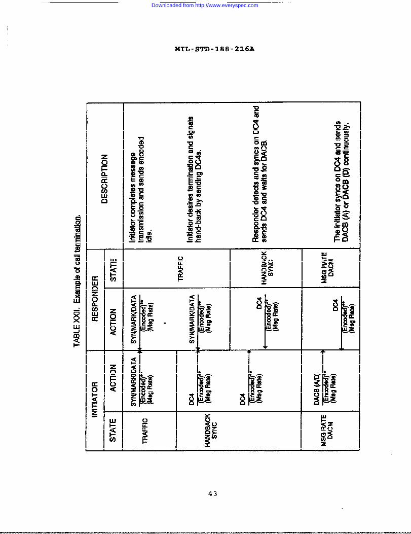
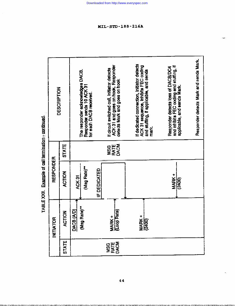
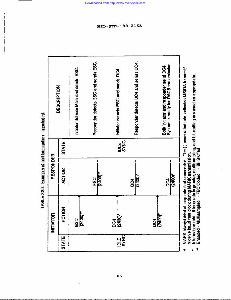
(break by slave) - retu~ to idle -Example of call termination . . . . .
XXIB
XXIIXXIIIXXIV
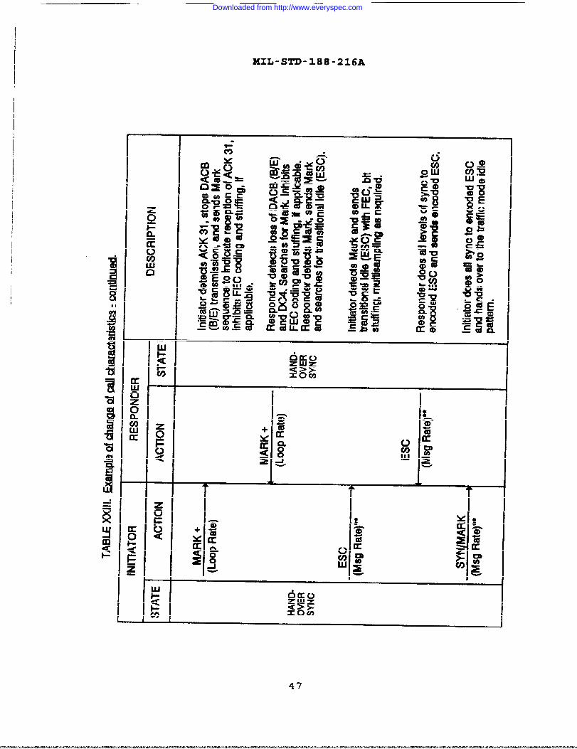
Example of change of call characteristicsConversion tables from loop rates to
information rates . . . . . . . . . . .Example of call initiation with ID establishment
XXVIXXVIIXXVIIIXXIX
Example of reject message . . . . . ● . . . . .Example of transmission complete return to idleExample of invalid characteristics . . . . . . .Timeouts and timeout actions . . . . . . . . . .
vi
Downloaded from http://www.everyspec.com

MIL-STD-188-216A
APPENDIX PAGE
APPENDIX A DUPLEX MESSAGE PROTOCOL . . . . . . . . . . . . . 71APPENDIX B LIST OF ABBREVIATIONS AND ACRONYMS USED IN
MIL-STD-188-216 . . . . . . . . . . . . . . . 85APPENDIX C STATE DIAGM FOR DACM PROTOCOL . . . 91
APPENDIX D GOLAY CODING FOR DACM AND MESSAGE tiFIC : . . . 123
vii/viii
. .
Downloaded from http://www.everyspec.com

MIL-STD-188-216A
(This page intentionally left blank.)
—
Downloaded from http://www.everyspec.com
MIL-STD-188-216A
1. SCOPE
1.1 mose. The purpose of this document is to establishtechnical standards and Design Objectives (DOS) that arenecessary to ensure interoperability and to promote commonalityfor communications equipment and subsystems using Data AdapterControl Mode (DACM) procedures. Another purpose of this documentis to establish acceptable overall system performance in order tosatisfy diverse user requirements without the restrictions causedby interface interoperability problems. Message formatsspecified for use by the DACM are defined in AlliedCommunications Procedures (ACP-127), Communications InstructionsTape Relay Procedures; Defense Operating Instruction (DOI)-1O3,Defense Special Security Communications System (DSSCS) OperatingInstructions (U) System/Data Procedures; and Joint Army NavyAllied Procedures (JANAP-128), Automatic Digital Network(AUTODIN) Operating Procedures.
1.2 ~COD~. This document specifies the minimum requirementsnecessary to develop a Data Adapter Control Mode protocolprocedure. It is not the intent of this document to specify anyparticular hardware or software design or implementation. Messageformats are not specified in this standard.
1.3 @~lication. This document is applicable to the design anddevelopment of new equipment, assemblages, and systems usingDACM . This document is applicable also to the engineering andoperation of existing DACM systems. It is not intended thatexisting DA(!M systems be immediately converted to comply with thestandards contained in this document. New DACM systems and thoseundergoing major modification or rehabilitation shall comply withthe standards contained in this document subject to applicablerequirements of current procurement regulations. DACM can beused over common long haul and tactical communications circuits.In this case, both this document and Military Standard (MIL-S~)-188-IOC) shall apply.
1.4 Objectives The objectives of this document are to providesystem performa~ce requirements that ensure interoperation ofequipment and systems consistent with military requirements; toachieve the necessary degree of performance and interoperation inthe most economical way; and to prevent proliferation ofequipment serving the same or a similar function. The variety ofequipment shall be the minimum necessary to effectively supportthe missions of the government in accordance with Department ofDefense Directive (DODD) 4630.5, Compatibility and Commonality ofEquipment for Tactical Command, Control, and Communications.These objectives will be accomplished by continuing efforts inthe following areas:
1
Downloaded from http://www.everyspec.com
a.
b.
c.
d.
MIL-STD-188-216A
Standardizing user-to-user performance characteristics. —
Standardizing the type of signals at various interfacepoints in the applicable system.
Specifying maximum permissible degradation of a signalin the process of transmission and allocating thepermissible degradation among various parts of asys tern.
Defining performance parameters without specifying thetechnology that should be used to obtain the requiredperformance.
1.5 ~ds and DO= . The parameters and otherrequirements specified in this document are mandatory systemstandards if the word ‘shallW is used in connection with theparameter value or requirement under consideration. Nc)nmandatorysystem parameters and DOS are indicated as optional by the word‘should” in connection with the parameter value or requirementunder consideration. For a definition of the terns “systemstandards* and “design objective, n see Federal Standard (FED-STD)-1037, Glossary of Telecommunications Terms. Informationparagraphs, shown as notes, have been included to better definemethods currently in use with the DACM.
1.6 Tailoring . As a minimum, only those features or functionsspecified herein, necessary to ensure interoperability amongsystems, shall be implemented in an equipment item. While everyeffort has been made to include all the features necessary forprotocol implementation, certain aspects are dependent uponsystem application and must be tailored by the specificationwriter. These aspects include alarm functions, Mode VI blockgroup size, data rates, codes, messa9e fo~ts~ etc-
—
2
Downloaded from http://www.everyspec.com

MIL-STD-188-216A
2. APPLICABLE DOCUMENTS
2.1 Government documents
2.1.1 Standards. The following standards form a part of thisdocument to the extent specified herein. Unless otherwisespecified, the issues of these documents are those listed in theDepartment of Defense Index of Specifications and Standards(DODISS) and supplement thereto.
STANDARDS
FEDERAL
FED-STD-1037
MILITARY
MIL-STD-188-1OO
MIL-STD-188-171
MIL-STD-188-172
MIL-STD-188-173
MIL-STD-188-174
Glossary of TelecommunicationTerms
Common Long Haul and TacticalCommunication System TechnicalStandards
Interoperability Standards forInformation and Record TrafficExchange MODE I
Interoperability Standards forInformation and Record TrafficExchange MODE II
Interoperability Standards forInformation and Record TrafficExchange MODE V
Interoperability Standards forInformation and Record TrafficExchange MODE VI
2.1.2 Other Government documents, drawinqs. and,
publlcat ions.The following other Government documents, drawings, andpublications form a part of this standards to the extentspecified herein.
JANAP-128
DOI-103
3
Automatic Digital Network(AUTODIN) Operating Procedures
Defense Special SecurityCommunications System (DSSCS)Operating Instructions (U)System/Data Procedures
Downloaded from http://www.everyspec.com

2 .1.2.1
2 .1.2.2
ACP- 117
ACP -127
MIL-STD-188-216A
Allied Routing Indicator Book
Communications InstructionsTape Relay Procedures
Department of Defense DirecE ives (DODD)
DODD 4630.5 Compatibility and Commonalityof Equipment for TacticalCommand, Control andCommunications
DODD 5000.1 Defense Acquisition
Jo int Tactical Communications Office (TRI-TAC~
~-Bl-1205-0085 Performance Specification forSwitching Set, MessageAutomatic AN/GYC-7
2.2 Order of precede nce. In the event of a conflict between thetext of this standard and the references cited herein, the textof this standard takes precedence. Nothing in this standard,however, supersedes applicable laws and regulations unless aspecific exemption has been obtained.
2.3 Source of documents
2.3.1 Gove rnment sDec ificat ions. Standards. and handbooks.Copies of the referenced federal and military specifications,standards, and handbooks are available from:
Department of Defense Single Stock PointCommanding OfficerNaval Publications and Forms Center5801 Tabor AvenuePhiladelphia, PA 19120-5099
For specific acquisition functions, these documents should beobtained from the contracting activity or as directed by thecontracting activity.
2.3.2 Other Gover~nt document~ . Copies or other Governmentdocuments required by contractors in connection withspecification acquisition functions should be obtained from thecontracting activity or as directed by the contracting activity.
4
- —.-cc-_—— — . . -— - -— —. — .-
Downloaded from http://www.everyspec.com

MIIJ-STD-188-216A
3. DEFINITIONS
3.1 Definition of terms Definition of terms used in this
document shall be as spe~ified in FED-STD-1037. Those
definitions of terms unique to DACM and not defined in FED-STD-1037 are provided in the following subparagraphs.
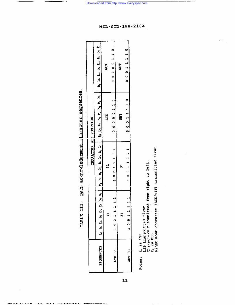
3.1.1 ~K 3~.acknowledgementcharacters, ACK
3.1.2 Channel.1037) .
The Data Adapter Control Block (DACB) positivesequence consisting of four contiguousACK 31 31 (see Table III and 4.2.2).
A path along which signals can be sent (FED-STD-
3.1.3 DA/MS. Connection of one of the following: DA to DA, DAto MS, Ms to MS, or MS to DA.
3.1.4 DACB ack nowle@e ment seaue nc~. There are four DACBacknowledgement sequences (see 5.2.2) :
ACK 31 (see 5.2.2.1)-:: WET 31 (see 5.2.2.2),
DACB(INV) (see 5.2.2.3),:: DACB(F) (see 5.2.2.4).
3.1.5 DACM. DACM is a synchronous character-oriented protocoldesigned for use prior to passage of data traffic. DACMestablishes or determines the transmission characteristics underwhich data traffic may be passed and describes the data trafficthat may be passed.
3.1.6 Exces sive unexnec ted characters. A situation where a Data
Adapter/Message Switch (DA/MS) receives 170 or more contiguouscharacters that are not acceptable when received.
3.1.7 Glare. A situation where DA/MS try to initiate DACMsignaling to each other at the same time (see 5.6) .
3.1.8 Han dback. The process of going from the traffic mode backto the DACM.
3.1.9 Handover. The process of going from DACM to the trafficmode.
3.1.10 Information rate. The minimum number of bits (l’s andO’s) per unit of time, usually seconds, required to convey usefulinformation (for example, 2400 bps) . This is also referred to asmessage rate.
3.1.11 Initiator. The party starting a procedure and leading inthe steps of the procedure.
5
Downloaded from http://www.everyspec.com

MXL-STD-188-216A
3.1.12 LoOD rat?. The rate at which bits are exchanged betweena DA/MS and the transmission/c~tographic equipment.
3.1.13 Master-sla ve relationshiDf3. On circuit switchedconnections, calling station is the master, called station isslave. On dedicated connections, predefine data base parametersdefine the relationship. The master-slave relationship shouldnot be confused with the initiator-responder relationship.
3.1.14 Message svnch ronizat-ion. The process whereby the DA/MSsharing a connection cooperatively progresses from an unknown orambiguous message state to a common known start-of-message state,i.e., to either sending the first block of a message or toexpecting the next input block to be the first block of amessage.
3.1.15 ResD onder. The party reacting to the start of aprocedure and following in the execution of the procedure.
3.1.15 SYN
a. Traffic State idle character or sequence.
1.2.3.
b. DACM
1.2.3.
MODES I and VI; even parity SYN character,MODES II and V; one or more logical 1,MODE VII; Flag sequence.
idle characters or sequence.
ESC; handover SYN character/s,DC4 ; handback SYN character/s,MARK State; handback State.
3.1.17 Traffic mod~. The mode between DA/MS that messagetraffic (Modes I through VII) is sent.
3.2 Abbreviations d a~s Abbreviations and acronyms usedin this document are as definedgin FED-STD-1037. Thoseabbreviations and acronyms unique to this document and notdefined in FED-STD-1037 are provided in Appendix B.
—6
Downloaded from http://www.everyspec.com

MIL-STD-188-216A
4. GENERAL REQUIREMENTS
4.1 Data adapter funct ion. The Data Adapter function is toimDlement the Data Adapter Control Mode (DACM) which was designedoriginally for operati~n over the ~1-TAC system. Figure IB -illustrates a typical Circuit Switch (CS)/Message Switch(MS)/Data Adapter (DA) connection which will use the DACM.Message switches are capable of operation with a DA on adedicated or circuit switched basis.
4.1.1 DACM net work Dara.mete r~. Data access to a DA/MS shallaccommodated on a dunlex diqital basis at one of the standardloopDACM
and information-rates & listed in table I. In additionshall:
be
the
a. Remuire a duplex circuit.b. Op&rate at afiy information rate during transmission.c. Initially operate at an information rate of 2400 bps.
TABLE 1. DTE to 100D transfonnatJ ‘on~.
INFO RATES LOOP RATES (bps)
(bps) 2400 4800 9600 16000 32000r
45.45 (Bawl) x x x x x
50 x x x x x
75 x x x x x
150 x x x x x
300 x x x x x
600 x x x x x
1200 x x x x x
2000 x x x,2400 x x x x x
4000 x x
4800 x x x x
8000 x x
9600 x x x
16000 x x
32000 x
7
Downloaded from http://www.everyspec.com

MIIJ-STD-188-216A
!!l—-
. . . . . . . . . . ----- . . . .. .
.. ..B
. . ..- . . ..-. . . . . . . . .. . . . . . . . . . . . . . . . . . . . . .-”” ““
ii ‘ BI
ww ................-
!
.... . ... .
L
.
f!.Ill.
i!!m
8
Downloaded from http://www.everyspec.com

I
1
I4
MXL-STD-188-216A
4.1.2 Circuit establishment. The DACM should be used to set upcircuit parameters. The circuit initialization DACM shallprogress through the following five states.
Idle line.:: Idle synchronization.c. Idle rate DACM (at this time Data Adapter Control
Blocks (DACBS) are transmitted) .d. Handover synchronization.e. Traffic mode.
4.1.3 Parameter cha nq~ The changing of circuit parametersshall progress through tie following five states.
Traffic mode.:: Handback synchronization.
Message rate DACM (at this time DACBS are transmitted) -:: Handover synchronization.e. Traffic mode.
4.2 ODeratlon.
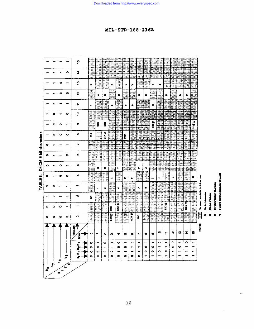
. The DACM is a duplex synchronous operation. TheDACM consists of synchronization characters, control characters,DACB characters and rate change MARK. All characters of the DACMconsist of eight bits (see table II) .
4.2.1 &WnChmu=atlOn ~dl~● . ●
characters There are twosynchronization characters: DC4 and ESC. These characters havean even number of logical 1 bits per character (see table II) .
4.2.2 Control characters. There are two sets of controlsequences each consisting of four contiguous characters (seetables II and 111) . Each character of the four charactersequence shall contain an even number of logical 1 bits. Thesesequences are:
WBT WBT 31 31.:: ACK ACK 31 31.
9
Downloaded from http://www.everyspec.com
MIL-STD-188-216A
I -
1 [ L&f .’..: “.; - .......
F 000 m
t- ,...0 --- ..:*.*..........,..............
o
0
0
0
El“.
. .. .
1
10
Downloaded from http://www.everyspec.com
MxL-sTD-n8-=m
o
0
d
dm
54
c
1-
r
v
F
c
c
c
r
r
r
rdm r
cc
v
UmM+w
‘d:u
.
11
Downloaded from http://www.everyspec.com

MIL-STD-188-216A
C&
UJ
tj
maxobC9
mn
tul-xA
dUJu3aii
12
Downloaded from http://www.everyspec.com

MIL-STD-188-216A
4.2.3 Data Adanter Contro 1 Block (DACB) . The DACB consists of37 characters (see figure 2) . The DACB is composed of 5 framingand 32 identifier positions.
4.2.3.1 Frarninq characters. The five framing characters of theDACB are (see table 11) :
Start of Text (STX) .:: 31.
End of Medium (EM).;: End of Text (ETX).e. Block parity (BP).
With the exception of BP, all framing characters shall contain aneven number of logical 1 bits. Because of the manner that BP isgenerated, BP may be any character composed of eight bits.
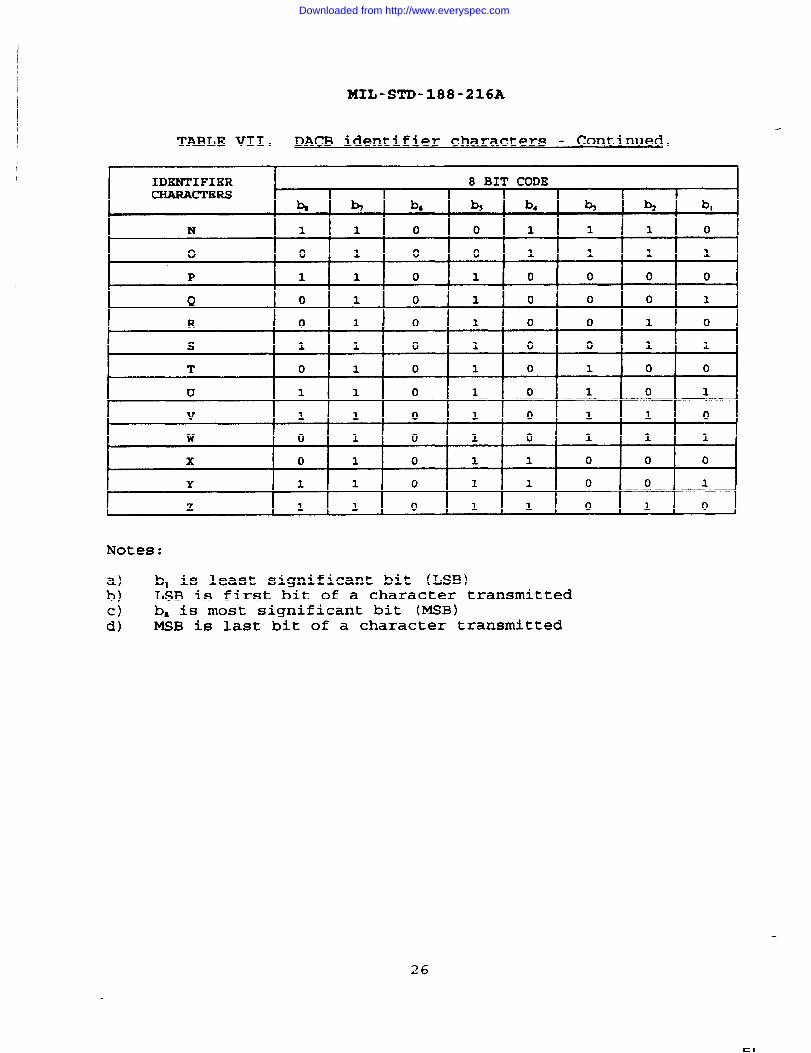
4.2.3.2 Jdent ifier DOS ition. The identifier characters areshown in table VII and are used in the 32 identifier characterpositions. Not all identifier characters are used in allpositions. All identifier characters shall contain an odd nuxnberof logical 1 bits. Identifier characters which are notrecognized as one of the assigned characters shall be treated aserrors.
4.2.4 Rate chanae MARK. The DA places the loop in the MARKstate whenever the information rate of the DACB changes.
13/14
Downloaded from http://www.everyspec.com

MIL-Sm-188-216A
(This page intentionally left blank.)
Downloaded from http://www.everyspec.com
MIL-STD-188-216A
5. DETAILED REQUIREMENTS
5.1 Data adaDte Drot Ocol . The DA may be a separate device orpart of a Data T=~inal Equipment (DTE), Message Switch (MS), orcommunications center. Figures 1A and lB show a typical systemthat may be used to interconnect DA devices to each other and toan MS. This standard defines protocols exchanged and actionstaken between DAs or between DAs and MSs. IWO levels ofinterfaces shall exist for circuit switched comections betweenDAs or between DAs and MSs.
a. Signaling and supervision information exchanged betweenthe telephone and various Circuit Switches (CS) toestablish a data circuit path.
b. After the data circuit path is set up, the DACMcoordination between DAs or between DAs and MSs shalltake place. All the foxms of this coordination aredescribed herein. This coordination also applies todedicated circuits between DAs or between DAs and MSs.
5.1.1 Protocol control . Circuit switched DA access shallrequire a control message exchange between DAs. This controlmessage is known as a DACB. The state which DACBS may betransferred is known as the DACM. Prior to initiation oftransmission of one or more traffic messages for either circuitswitched calls or dedicated loops, the initiator shall send aDACB which shall be used to establish the parameters for theensuing data transmission. Any change in DACB characteristicsshall cause a new DACB to be transmitted. The message trafficshall be transmitted following acknowledgement of the DACB andsynchronization at the DTE information rate. After completion ofthe message traffic transmission, a DACB may be transmitted(nmnally by the Originating unit) to initiate the calltermination sequence. A detailed description of the operation ofthe DACM protocol is given in Appendix C.
5.1.2 Proto CO1 rates
5.1.2.1 DACB rat?. DACBS should be sent at idle rate orinformation rate as defined in table I.
5.I-2.I.1 ~. Idle rate shall be defined as aninformation rate of 2400 bps. If the loop rate is higher than2400 bps, the bits shall be transmitted using multisamplingtechniques (see 5.3.1.1).
5.1.2.1.2 Information rate Information rate is the rate thatmessage traffic shall be ex;hanged (see 5.2.1.2) .
5.2 DACM. The DACM shall consist of the methods and proceduresrequired to establish, and control a tactical data communication
15
Downloaded from http://www.everyspec.com
MIL-STD-188-216A
charnel between DTEs, DTE/MS, or MSs. The DACM shall be
transparent to the information flow through the channel. The
DACM includes the description of the following:
a.b.
e.f.
9“h.
;:k.1.
DACB types,DACB format,DACB acknowledgement,DACB framing characters,DACB signaling procedures,Synchronization characters,Handback request detection,Break sequence,WK detection criteria,Error contrOl,Message to loop rate transformation, andCommunication SECurity (COMSEC) control.
5.2.1 DACB format A DACB shall consist of 37 8-bit characters(see tables II, IV; V, VIA, VIB and figures 2 and 3). Framing of
a DACB shall be accomplished by a Start of TeXt (STX) characterin position l,followed by the framing character 31 in position 2(see tables II, VIA, and VIB) and End of Medium (EM) , End of Text(ETX), and Block Parity (BP) in Positions 35~361and 37respectively. A3.1 framing characters, with the exception of BP,
shall have an even number of logical 1 bits per character (seefigure 3). BP may have an odd or an even number of logical 1bits. 1111 identifier characters shall have an odd number oflogical 1’s. Valid contents of DACBS shall be as defined in thefollowing subsections. The minimum valid contents of each DACB
generated shall be allowed as summarized in table VII.
Note: The character ’31” of the DACB, identified by Col- 9,
row 15 of table II, is the label for the second framing characterof the DACB and not a number.
5.2.1.1 Secur,ty class ifica “ d handlinq mocedures . These
two identifier=characters (p~~?~i~~s 3 and 4 of DACB) shall
identify the classification parameter of the channel. These
characters shall be NUL except when the transmission statuscontrol character (position 13) is NUL, B, or E. These allowable
security classification indicators shall be in accordance withtable VIII.
NOTE: ADP Security Directives, and Standards Operating Procedures
may effect the implementation concerning these security
identifiers codes. Perfomnce requirements for eachimplementation should include the use of the securitYidentification of the channel.
16
Downloaded from http://www.everyspec.com

I1
I
MIL-STD-188-216A
I
I
I
I
TABLE IV. Data adante r contr 01 block format .
Character Character Ftmction ReferencePosition Description Table
1 Framing Start of Text N/ACharacter - STX
2 Framing Framing Character - N/A31
3-4 Security Security of Channel VIIIRepeated Identifier(2 character)
5 Information Rate Identifies the IXInformation Rate
6 Spare Available for Future N/AUse - NUL
7 Codes Message Code x
8 DTE Select Identifies the DTE XIChannel Selected orIdentified
9 Message Fomat Identifies Message XIIFormat Utilized
10 Channel Control Identifies Charnel XIIIProcedures Control Procedures
Utilized
11 Error Control Identification of XIVError ControlTechnique Utilized
12 Precedence Identifies Precedenceof Message
13 DACB Types Identifies Purpose XVIfor Transmission ofDACB
14 Mode VI Group Defines Number of XVI ISize Blocks Per Group
15 Data Mode Control Identifies Whether XVIIIData Mode ControlShall be Inhibited
17
.
Downloaded from http://www.everyspec.com
i
MIL-STD-188-216A
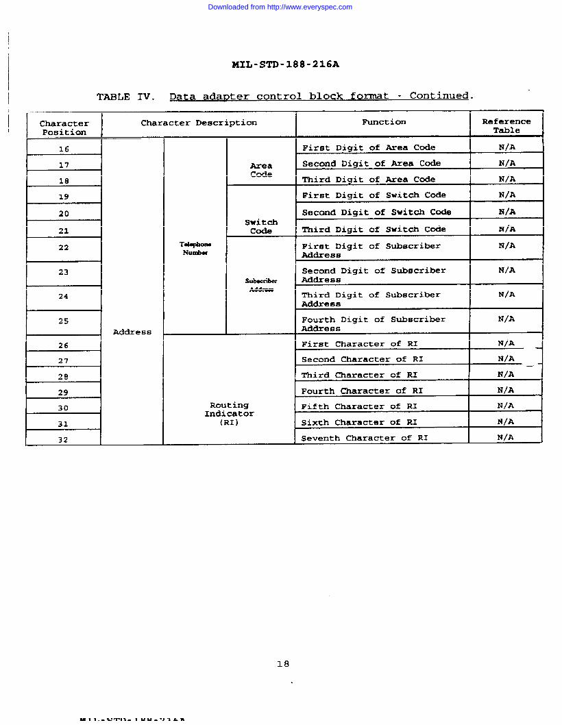
TABLE IV. Data adapt er control block fomat - Continued.
I CharacterPosition
16
H-I 20
I 21
22
I 23
I 24
25
I 26
t-+-
i-=----i 30
I 31
I 32
Character Description
Address
TokphonsNumber
AreaCode
Switchcode
SubscriberAddren
RoutingIndicator
(RI)
IhlnctionI
ReferenceTable
First Digit of Wea Code N/A
Second Digit of -ea Code NIA
Third Digit of &ea Code N/A
Pir6t Diqit of Switch Code N/A
Second Digit of Switch Code N/A
Third Digit of Switch Code IW/A
First Digit of Subscriber lU/AAddress
Second Digit of Subscriber N/AAddress
Third Digit of Subscriber N/AAddre 8s
Fourth Digit of Subscriber N/AA&Iress /
First Character of RI N/A+
Second Character of RI N/A—~
Third Character of RI N/A
Fourth Character of RI N/A
Fifth Character of RI N/A
Sixth Character of RI N/A
Seventh Character of RI N/A
18
Downloaded from http://www.everyspec.com

MIL-STD-188-216A
TABLE IV. Data ada~t er control bu fo~t Conclude d.
Character Character Function ReferencePosition Description Table
33 DTE Type Identification of DA N/ACapabilities or Requestfor Specified DT’ECapabilities (see5.2.1.14)
34 DACB change Identification of DACB XIX(same as previous orchanged )
35 Framing EM - End of Medium N/A
36 Framing ETX - End of Text N/A
37 Framing BP - Block Parity N/A
19
Downloaded from http://www.everyspec.com

MIL-STD-188-216A
TABXJi V. actez aaez~ .
DACMIdentifierCharacter
Position(s)
Description
k ●
Character Setting by DACB Type
F*DC2●
STX STX
31
Framinc# I STX ST!X
31
STX I STx I STXI I
STX STX STX
31
1
Framing 31 31 I 31 31 31 31 312
Security &/
z
NUL]I!UULJNULI 1
3&4
H H HInfo Rate I A/Spare NuLpl’uLINuL
I 16
I 2/l-7
DTE Select I 518
NuL9
Channel I AlControl ‘1 “ Im10
11
Precedence ! &/ NuLINuL@JLI I
12
DACB Types c D FENQ I INV I A1 i
13
‘1 2’ I -14
zData Mode I Al z z z z zz15Control I
==L-16-32
0
0
0
0
0
0
0012/10 033b,
33bj
33b3
33b4
33b,
33be
Paper Tape &/ o g/ o oo
00Card Unit 1 &/
o 0uoo
oTerminal
I
&/Display/
o
Storage I
20
Downloaded from http://www.everyspec.com

I
MIL-STD-188-216A
DACMIdentifierCharacter
Position(s)
33h
34
35
36
37
NWI’ES:
. This bit position is a spare and shall be set to logical O.
If a DACB (INV) is sent because:
the received DACB characteristics cannot be accotnmoda ted or& the received DACB characters are inconsistent with the stored classmarks
associated with the RI in the received DACB.
Then each character position shall contain a valid character. The DACB (INW
character positions, except 3, 4, and 12, shall specify the characteristicsacceptable to the MS/DA sending the DA= (1~) .
The Message Switch/Data Adapter shall have the option of placing NUL characters inpositions 16 through 25, inclusive where appropriate (i.e. , dedicated circuits) .Valid RI characters shall always be inserted in positions 26 through 32 inclusive.
The Message Switch/Data Adapter transmitting this DACB must place one of the validcharacters or bits in this position. Z%e characters or bits to be used are thosespecified in 5.2.1.1 through 5.2.1.15.
Multiple DTE Data Adapters and Message Switches shall place an appropriate validcharacter in this position. Single DTE Data Adapters shall place NUL in thisposition.
This position is a block parity character and is defined in
This position is a parity bit and is the logical sum of allcharacter such that the number of logical 1’s is odd.
DACB types (see 5.2.1.10), p0f3itiOn 13 of D-.
paragraph 5.2.3.1.
the bits of the
21
Downloaded from http://www.everyspec.com

MIL-STD-188-216A
1 I i I I I I I I I I I I I I I I I I I I IL- 4 0 0 0 -/ 0 a a 0 0 J 4 c
z- 0 0 a G a 0 0 a a a 0
I i i 1 1 1 1 1
E“ 0 . a a a + . a a e 0 a a a c
z- . a a a a 0 a a a 0 a 0 a a
Ai- . m a 0 a 0 a a a a
s a 0 - 4 a a 0 a a a a a a a a a a c
M . M m m
‘1vivivlv l-1
a- 0 a a a 0 c
a- - a a a a c
Xi- a 0 . a a a c
&- a a a a a . a a 0 0
~- 0 a a 0
S* a
J a 0 a a a a a a a a 0 c
s“ a 0 d a a a a a a 0 a c
I
illr
a a a a o a o a c
a a a o a a ‘3- a a
.
0 . a 0 0 a a 0 a a a c
a 0 a e a 0 a e a a a c
a a a 0 0 a a m 0 a m
a a a a a a 0 a . a a 0 a a a a c
. . . m d a a a a c
a a 0 a a 0 a 0 a a a a
L ‘ I& u
22
Downloaded from http://www.everyspec.com

MIL-STD-188-216A
a- - 0 0 0 . a m 0 - d 4 a . a a a 0 a 0 a
n- o 0 a . 0 0 a 0 d H a a . a a a 0 m
.
a- O a 0 a a 0 . a a a 4 . 0 a w 0 0 a 0 0
a“ o a a a a a a 0 a a m a a a a . a . . a . 0 a a
x.? a a a 0 0 . . . a 0 a 0 a a a a e a 0 0 a a “ m
a 0 0 a a e 0 a a e a e a a a a.
a- Oa a a a 0 0 0 0 a a a
A - a m m a a a a m a 0 0 a . m 0 . a d a
a- - a a . 0 a a m a 0 0 a a a a 0 . a
:az Y m w a
c < m u Q> x z 0 0 $
● 4 ii z h b “ ~u! u z w - A a!
6z
1111 J 1 I 1 1 1 1 1 1 1 I I I I 1 1 1 1 1 1 n 1 1 , J
23
Downloaded from http://www.everyspec.com

MIL-STD-188-216A
010
010
xo .
*
zw
&
nzUJ
I
3
(!6
24
Downloaded from http://www.everyspec.com

MIL-STD-188-216A
TABLE VII. PA~,.
ld~~fzer character~ .I
IDENTIFIER 8 BIT CODECHARACTERS
F
b b bb b~ b, b b blb
1 0 0 0 0 0 0 0r
ENQ 1 0 0 0 0 1 0 1
INV o 0 0 0 0 1 1 1
DC1 1 0 0 1 0 0 0 1
DC2 1 0 0 1 0 0 1 0
DC3 o 0 0 1 0 0 1 1
SP o 0 1 0 0 0 0 0
0 1 0 1 1 0 0 0 0
1 0 0 1 1 0 0 0 1
2 0 0 1 1 0 0 1 0
I 3 111011 111010 11111
I 4 101011 111011 10101
5 1 0 1 1 0 1 0 1
6 1 0 1 1 0 1 1 0
7 0 0 1 1 0 1 1 1
I 8 I 01 01 1 111110 10101
9 1 0 1 1 1 0 0 1
A 1 1 0 0 0 0 0 1
B 1 1 0 0 0 0 1 0
c o 1 0 0 0 0 1 1
I D 111110 101011 10101
I E 101110 101011 10111
I F 101110 1010]1 11101
G 1 1 0 0 0 1 1 1
H 1 1 0 0 1 0 0 0
I o 1 0 0 1 0 0 1
J o 1 0 0 1 0 1 0
K 1 1 0 0 1 0 1 1
L 1 1 0 0 1 1 0 0
M 1 1 0 0 1 1 0 “ 1
25
Downloaded from http://www.everyspec.com
MIL-STD-188-216A
I
TABLE
i
VII. DACB identifier characters - Continued.
r 1IDENTIFIER 8 BIT CODECHARACTERS
,
4 b b~ b~ b, b b I b,, I
N 1 1 0 0 1 1 1 0
0 0 1 0 0 1 1 1 1
P 1 1 0 1 0 0 0 0
Q o 1 0 1 0 0 0 1
R o 1 0 1 0 0 1 0
s 1 1 0 1 0 0 1 1
T o 1 0 1 0 1 0 0
u 1 1 0 1 0 1 0 1kv 1 1 0 1 0 1 1 0
w o 1 0 1 0 1 1 1
x o 1 0 1 1 0 0 0
Y 1 1 0 1 1 0 0 1
z 1 1 0 1 1 0 1 0 i
Notes:
a) bl is least significant bit (LSB)b) LJSB is first bit of a character transmittedc) ba is most significant bit (MSB)d) MSB is last bit of a character transmitted
26
Downloaded from http://www.everyspec.com

MIL-STD-188-216A
TABLE VIII. Security classification W handlma.
nrocedu rq.
1 1 1
Identifier Characters Identification
I “Yn RI Community
I I TOD Secret I
Ss Secret
I cc IConfidentialE I
EE EFTO (Encrypted forTransmission only)
I IUnclassified[
I NULNULINo message associated withthis DACB
NOTE : ADP Security Directives and Standard Operating Proceduresmay effect the implementation of these security identifier codes.Performance requirements for each implementation should includethe use of the security classification of the channel.
5.2.1.2 Infomtion rate. This identifier character (position 5of DACB) shall identify the infomnation rate of the channel (seetable I). The information rate indicators shall be inaccordance with table IX.
5.2.1.3 Character 6 of DACB. This identifier character(position 6 of DACB) shall be a NUL, and is a spare.
5.2.1.4 Codes. This identifier character (position 7 of DACB)shall identify the DTE message code. The indicators shall be inaccordance with table X.
5.2.1.5 DTE select. This identifier character (position 8 ofDACB) shall identify the DTE terminal requested within the DACB.For DACB (F) see 5.2.2.4. MSs and DAs with a single DTE charnelshall not transmit DACB (INV) due solely to receipt of DC1, DC2,or DC3 in this character position. A multiple DTE DA shalltransmit a DACB (INV) if an incompatible identifier character isreceived in a DACB. The indicators shall be in accordance withtable XI.
5.2.1.6 Messaqe formaC. This identifier character (position 9of DACB) shall identify the format of the message(s) to betransmitted. The indicators shall be in accordance with tableXII.
XK
27
Downloaded from http://www.everyspec.com

MIL-STD-188-216A
I
TABLE IX. Information rate.
1 Identifier Characters
B
c
D
E
F
G,
Ht
J
K
I L
M
N
o
z
I NUL
I
Identification I
45.45 baud II
50 bps I75 bps
150 bps
300 I
600 bps I
1200 bps
2400 bps
4800 bps
9600 bps
16000 b~s
32000 bps
2000 bps
4000 bps
8000 bps
Remain at current informationrate
No information rate associatedwith this DACB
—
28
ZI
u ,x In &
Downloaded from http://www.everyspec.com

MIL-STD-188-216A
TABLE X. !Z!QSXl-
t I
Identifier Characters Identification
A ASCII odd parity
B IA No. 21
c Continuous random bit streamand facsimile
kI D 14 out of 8 (IBM) code 10 unit
I I start-stopE EBCDIC. (Extended Binaxy
Coded Decimal InterchangeCode )
F Field data
I G ASCII even parity (data)
N Nonstructured format magnetictape
I o I Structured fomat magnetic
I I tape
I NUL INo code identified by thisDACB
NOTE : The equipment designer shall guard against the generationof false handback request.
TABLE XI. DTE se lec~.
Identifier Characters IdentificationI -
DC1 DTE -1
DC2 DTE -2
I DC3 DTE -3
I NUL IOnly one DTE or selectionbased on character 33 of DACB
29
Downloaded from http://www.everyspec.com

MIL-STD-188-216A
TABLE XII. Bessaqe format .
I
Identifier Characters Identification, A
A ACP-127
B JANAP-128, Data
c ACP-127 modified (DOI-1O3 Special)
D JANAP-128, Teletypewriter
E Special Format 1,
F Special Format 2A
G JANAP-128 modified (DOI-1O3 Standard
H ACP-127 NATO SUPP 3
I DOI-103 (CRITIC)1
SP RESBRVED for MS trunk coordinationI 1
No special format (a valid format coordinated bymeans other than by DACBS)
5.2.1.7 Channel control ~rocedures. This identifier character(position 10 of DACB) shall identify the operational mode of theDA (or the DTE connected to the DA) or the operational mode ofthe MS during message transmission. Modes I, II, V, and VI aredefined in MIL-STD-188-171, 172, 173, and 174. Mode VII isdefined in ‘IT-B1-1205-0085. The indicators shall be inaccordance with table XIII.
TABLE XIII. channel control nroc edures.
Identifier Characters Identification
A Mode I - Continuous (MXL-STD-188-171)
B Mode 11 (MIL-STD-188-172)
E Mode V (MIL-STD-188-173)
F Mode VI (MXL-STD-188-174)
G Mode I - Block-by-Block (MXL-STD-188-171)
H Mode VII (’lT-Bl-1205-0085)
J Duplex Message Protocol ~/
Unspecified - utilized between DAs for facsimile andspecial DTE
NOTE : ~/ Duplex Protocol (Generic Gateway) - A Channel Control Procedure usedby Special Community Message Switches (see Appendix A)
30
Downloaded from http://www.everyspec.com

ZJUL-STD-188-216A
I
I
5.2.1.8 Error control This identifier character (position 11of DACB) shall identif~ the error control technique to be_usedAintransmitting or receiving a message. The indicators shall be inaccordance with table XIV.
TABLE XIV. ~=
t
1
Identifier Characters
A
D
E
I
Identification
Multisampling - non bit framing (see 5.2.9.1.2)
1/2 rate Golay without multi-sampling (see
1/4 rate Golay (1/2 rate Golay withoutmultisampling with double codewordtransmission, see Appendix D)
1/8 rate Golay (1/2 rate Golay withoutmultisampling with quadruple codewordtransmission, see Appendix D)
Multisampling - bit framing (see 5.2.9.1.1)
5.2.1.9 Precedenc e. This identifier character (position 12 ofDACB) shall identify the precedence of the channel. Theindicators shall be in accordance with table XV.
TABLE XV. Precede nc?.
Identifier Characters Identification
Flash override (CRITIC, ECP)
Flash
Immediate
Priority
Routine or precedence stated only in messageheader(s)
NOTE : Standard Operating Procedures may effect the implementation of thesePrecedence identifier codes. Performance requirements for each implementationkhan include the use of the precedence of the channel.
31
Downloaded from http://www.everyspec.com

MIL-STD-188-216A
I
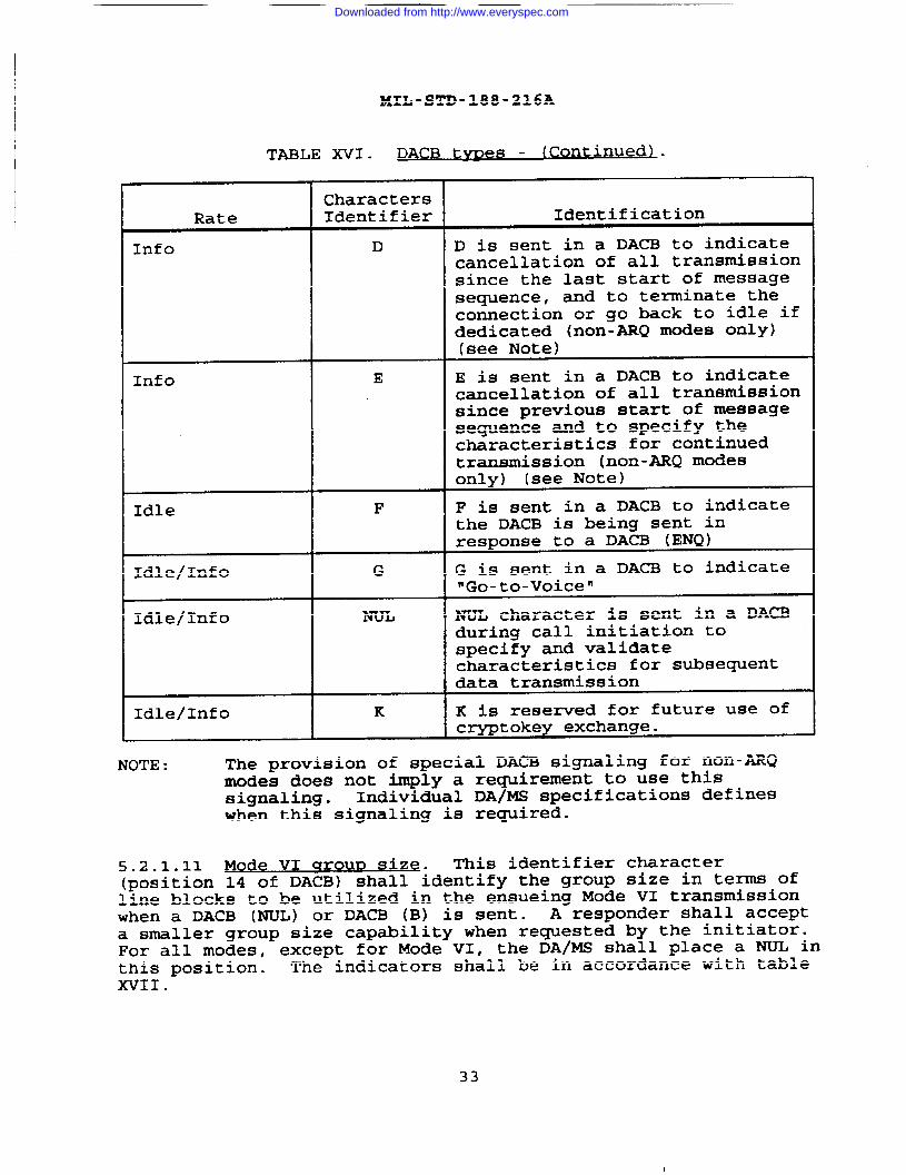
5.2.1.10 DACB tw e~. This identifier character (position 13 ofDACB) shall identify the reason for transmission of the DACB, orto request action(s) to be taken by the receiving DA/MS. Thereare 12 types of DACBS. The type of DACB is determined by thecharacter in position 13. DACBS may be used to inquire andverify the identity of the distant end, to establish or changeparameters, to terminate a call or return to idle, or to respond~o an invalid DACB. The indicators and acceptable transmissionrates shall be in accordance with table XVI (explained inAppendix C) .
TABLE XVI. DACB t- .
CharactersRate Identifier Identification
Information DC2 DC2 character is sent in a DACB(Info) to reject an incoming message
(non-mQ modes only, see note 1)
Idle (circuit ENQ ENQ is sent in a DACB to requestestablishment) a DACB (F) response to verify
the identity of the respondingDA/M.S
Idle/Info INV INV is sent in a DACB toindicate a received DACB cannotbe accommodated by theresponding DA/MS as specified in5.2.2.3
Idle/Info A A is sent in a DACB to indicatepresent transmission has beencompleted, no furthertransmission is intended and toterminate the connection or goback to idle if dedicated
Info B B is sent in a DACB to indicatethe received DTE to read thecontents of this DACB todetermine characteristicsspecified for continuedtransmission
Info c C is sent in a DACB to indicatetransmission of message(s) iscomplete, hold connection inidle state. Further messagetransmission will be preceded byanother DACB.
32
Downloaded from http://www.everyspec.com
MIL-STD-188-216A
TABLE XVI. DACB (Gontlnue,
tvnes d) .
CharactersRate Identifier Identification
Info D D is sent in a DACB to indicatecancellation of all transmissionsince the last start of messagesequence, and to terminate thecomection or go back to idle ifdedicated (nOn-ARQ m~ee OnlY)(see Note)
Info E E is sent in a DACB to indicatecancellation of all transmissionsince previous start of messagesequence and to specify thecharacteristics for continuedtransmission (non-ARQ modesonly) (see Note)
Idle F F is sent in a DACB to indicatethe DACB is being sent inresponse to a DACB (ENQ)
Idle/Info G G is sent in a DACB to indicate‘Go-to-Voice”
Idle/Info NUL character is sent in a DACBduring call initiation tospecify and validatecharacteristics for subsequentdata transmission
Idle/Info K K is resemed for future use ofcryptokey exchange.
NOTE : The provision of special DACB signaling for non-ARQmodes does not imply a requirement to use thissignaling. Individual DA/MS specifications defineswhen this signaling is required.
5.2.1.11 Mode VI c?roun size. This identifier character(position 14 of DACB) shall identify the group size in terns ofline blocks to be utilized in the ensueing Mode VI transmissionwhen a DACB (NUL) or DAm (B) is sent- A responder shall accepta smaller group size capability when requested by the initiator.For all modes, except for Mode VI, the DA/MS shall place a NUL inthis position. The indicators shall be in accordance with tableXVII.
33
Downloaded from http://www.everyspec.com

I
MXL-STD-188-216A
TABLE XVII. Mode VI qro Url size.
Identifier Characters
I A
B
c
DI
Identification
32
64
96
16
Not applicable
5.2.1.12 ~. This identifier character (position15 of DACB) shall identify whether Data Mode Control (DMC) modeof operation shall be used (see 5.5.2) or inhibited. Uponinitial establishment of a call (circuit), the DMC shall beenabled. The indicators shall be in accordance with table XVIII.
TABLE XVIII. Data mode control .
r I 1Identifier Characters Identification
I 4
A Data mode control inhibited
z Remains in present state
[ IData mode control employed I
5.2.1.13 XiQZww. The address (positions 16 through 32 of theDACB) shall contain addressing information of the DA/MSoriginating the DACB and shall consist of two fields; thetelephone number of the station and the Routing Indicator (RI) ofthe station. The station telephone number shall be constructedin accordance with the associated digital circuit switchnumbering plan. me 10-digit number (area code, switch code andsubscriber address) shall be used= The telephone number shall beleft justified. Unused portions of the telephone number shall beset to “NULs”. The RI field shall be constructed in accordancewith the applicable community RI directoq (see ACP-117) . The RIshall be left-justified in the field. Unused portions in the RIfield shall be filled with NUL characters. For DA/MSs withmultiple channel capability, the RI, for the specific DTE channelin character position 8 of the DACB, shall be inserted incharacters 26-32 of DACB. If no DTE is connected to a specificchannel, positions 26-32 of DACB shall be filled with ‘NULsw.
s=z.~blq QNLuQ= This identifier character (position 33 ofthe DACB) shall identify specific terminal equipment.
34
Downloaded from http://www.everyspec.com
a.
b.
c.
d.
e.
f.
9-
h.
i.
MIL-STD-188-216A
A logical 1 in bit position 1 shall indicate pageprinter.
A logical 1 in bit position 2 shall indicate a papertape unit.
A logical 1 in bit position 3 shall indicate a cardunit.
A logical 1 in bit position 4 shall indicate a terminalacting as a display or storage device.
A logical 1 in bit position 5 shall indicate a magnetictape unit.
A logical 1 in bit position 6 shall indicate afacsimile unit.
Bit position 7 shall be a spare and shall be set tological O.
A logical 1 in more than one position shall indicate acombination of the above devices and capabilities.
Bit position 8: sum of logical 1s, such that the numberof logical 1s are odd.
A DA/MS sending a DACB (F) or DACB (INV) shall set theappropriate bit(s) for the DTE(s) attached tO the sPecific DTEcharnel when position 8 of the DACB being responded to is DC1,DC2 , or DC3; or set the “logical 1“ of all the DTE types on allchannels when position 8 of the DACB is NUL. In DACB (NUL), DA~(B), and DACB (E) a specific bit shall be set for the type ofterminal equipment requested. If a specified DTE channel (DC1,DC2, DC3, or NUL in position 8) does not have specified terminaltype, a DACB (INV) shall be sent indicating the terminal typesavailable on the specified DTE channel.
5.2.1.15 PACB chanq~. This identifier character (position 34 ofthe DACB) shall identify whether the DA/MS transmitting a DACB iscapable of changing its characteristics or has changed any of itscharacteristics from the previously transmitted DACB (providedposition 13, DACB type, has not changed) . Whenever DACB (DC2),DACB (ENQ), DACB (A), DACB (C), DACB (D), DACB (F), or DACB (G)is transmitted, character position 34 shall always be a NULcharacter. Whenever a DACB (INV) is transmitted, characterposition 34 of the DACB (INV) shall be the same as that of thereceived DACB to which the DACB (INV) responds. Whenever DAC!B(~L) , DACB (B) , or DACB (E) is transmitted, character Position34 shall be in accordance with table XIX.
35
Downloaded from http://www.everyspec.com

MIL-STD-188-216A
TABLJE XIX. ~.
I Identifier CharactersI
A
tB
Identification
DA/MS is capable of changingits characteristics. ThisASCII character (A) shall beused with first DACBtransxnissi on. It shall alsobe transmitted with eachchanged DACB when previouslytransmitted DACB had a “B” inposition 34
DA/MS is capable of changingits characteristics.Transmitted with each changedDACB when previouslytransmitted DACB had an “AW inposition 34
DA/MS not capable of changingits DACB characteristics
5.2.2 DACB acknowledqe men~. Upon reception of a correctlyframed DACB with correct parity, the receiver shall send one ofthe following.
a. Positive acknowledgement.
b. Interim
c. Invalid
d. Enquiry
acknowledgement.
response.
response.
5.2.2.1 Positive ackno wledqemenC. The positive acknowledgement
seauence shall be sent by the receiver in response to a DACB withco;rect parity and compatible identifiers specifying parametersacceptable to the receiver. The acknowledgement sequence shallconsist of ACK ACK 31 31 (see table III) . During thetransmission of the positive acknowledgement sequence, no othercharacter (data, framing, or control) shall interrupt this fourcharacter sequence.
5.2.2.2 ow~ . The Wait Before Transmit (~T)sequence shall consist of WBT WBT 31 31 (see table III and5.2.4.2). The WBT sequence shall be sent to acknowledge receiptof a properly framed correct parity DACB and to request thetransmitter to stop further transmission of DACBS. During thetransmission of this se~ence, no other characters (data,fraining, or control) shall interrupt this four character
36
Downloaded from http://www.everyspec.com

IMIL-STD-188-216A
I sequence. The receiver shall transmit the WBT WBT 31 31 sequence
I at 3 second intervals until the DACB is validated by thereceiver.
I
I 5.2.2.3 Invalid resnonse. The invalid reply shall consist of aI
DACB with INV in position 13. DACB (INV) shall be sent only in\ response to a DA@ (~), DACB (B) # DACB (E)# or not imPl~entedI DACB type, which is received correctly (no parity errors) and at
a logical time (see table XVI) , but that is received withcontents specifying parameters unacceptable to the receiver. In
I all cases, the DACB (INV) shall contain the proper identifiersexcept security and precedence. NUL characters shall be insertedfor security and precedence.
5.2.2.4 The response to a DA~ (ENQ) shall be
a DACB (F) . If the DACB ~ENQ) contains DC1, DC2 , or DC3 in
character position 8, a DA with only one DTE shall respond with aDACB (F) with NUL in character position 8. A DA with more than
one DTE shall respond with the same DC1, DC2, or DC3 received incharacter position 8.
5.2.3 DAC13 fr~a characters* . The DACB shall consist of 5
framing characters and 32 identifier characters (see 5.2.1.1through 5.2.1.15) for a total of 37 characters (see figure 2 andtables II, IV, and VI). The DACB framing characters shall seweto delineate the beginning and end of the DACB. Two of thesecharacters (STX and 31) shall precede the identifier charactersand three of these characters (~, E~# and BP) shall succeed theidentifier characters. The transmission of a DACB shall never beinterrupted by the transmission of any other characters except attermination of DACB transmission. The DACB framing charactersare described in 5.2.3.1 through 5.2.3.5 and are listed in tablexx.
5.2.3.1 ~- STX shall be the first framingcharacter of the DACB. ST2C shall not be included in the BPcheck.
5.2.3.2 Data adaDter cha racte 3X Character 31 shall be thesecond framing character of th= DA&B. Character 31 shall beincluded in the BP check. Character 31 shall be followed by 32identifier characters (see table VII) .
5.2.3.3 End of medium (EM~. EM shall be the third FRAMINGcharacter of the DACB and shall be the 35th character of theDACB . EM shall be included in the BP check. EM shall befollowed by the framing character sequence ETX BP.
5.2.3.4 End of kext (Em . ETX shallcharacter of the DACB and shall be theDACB . ETX shall be included in the BPbe preceded by EM and followed by BP.
37
be the fourth framing36th character of thecheck. ETX shall always
Downloaded from http://www.everyspec.com

MIII-STD-188-216A
TABLE XX. 12A~ fram inq and control cha racte rq.
I
,
FRAMING, IDLE
CONTROL
I STX
I
I ACK
I EM
I BSC
I D(24
I WBT
I 31
8 BIT C(3DB
4 b b6 b~ b4 b b bl
1 0 0 0 0 0 1 0
0 0 0 0 0 0 1 1
0 0 0 0 0 1 1 0
1 0 0 1 1 0 0 1
0 0 0 1 1 0 1 1
0 0 0 1 0 1 0 0
0 0 0 1 1 1 1 0
1 0 0 1 1 1 1 1 b
Notes:
a) bl is least significant bit (LSB)b) LSB is first bit of a character transmittedc) bs is most significant bit (~B)d) MSB is last bit of a character transmitted
5.2.3.5 Block narltv, (BP) . BP shall be the last framing
character of the DACB. BP shall always follow ET’X. BP shall befomed by the binaq addition without carry of each of the bitsin each row of a block starting with the second framing character(31) , including all identifier characters, the EM character, andETX character. When ETX is detected, the next character shouldbe compared bit for bit with the receiver generated BP character.These two characters should be identical. If they are not, theblock shall be considered to have a parity error (see figure 3).
5.2.4 ~ACB ~lqnal,
inq Procedures . Each DACB transmitted and eachacknowledgement sequence shall be sent with contiguouscharacters. No idle characters or other characters shall be sentbetween the defined DACB or acknowledgement sequence characterpositions.
5.2.4.1 DACB transmission. A DACB shall be sent continuouslyuntil receipt of an ACK 31 or until another appropriate response.Transmission of continuous DACBS shall be teminated upon receiptof an acknowledgement (ACK, ~T, DACB (1~) # or DACB (F)) for theDACB . After receipt of a WET sequence, no new DACB shall beinitiated until after receipt of acknowledgement sequence or DACB(INV) or a time-out has occurred. The termination shall occur atany character boundary during the transmission of a DACB. Once a
38
Downloaded from http://www.everyspec.com
MIL-STD-188-216A
WBT has been sent, any incoming DACBS shall be ignored until anACK sequence, DACB (F) , or DACB (INV) ~s been transmittedo
5.2.4.2 DACB acknowledqe~ t t a Sml‘esion. An acknowledgment
sequence (ACK ACK 31 31 or ~T ~~ 31 31) shall be sent 10 timesin response to a DACB. DC4 idle characters (see 5.2.5.1) shallbe allowed between acknowledgment sequences. The receipt of a
complete ACK ACK 31 31 or WBT WBT 31 31 sequence by a receivershall be required for validation of these control charactersequences. Termination of an acknowledgement sequence shalloccur on any character boundary following the detection, by theresponder, of the advancement of the initiator to the nextsignaling state.
5.2.4.3 DACB trans~● .
resno nse If the responder continuesto receive the same DACB after havi~g sent a response other thanWBT - i.e., ACK, DACB (F) or DAm (1~), it shall be ass~ed thatthe reaponae sequence has been lost or not yet received and/oracted upon by the initiator. The duplicate block(s) shall bedisregarded; however, the response to the previously answeredDACB shall be retransmitted. In the case of duplicate block(s)received after the transmission of WBT, those blocks shall bedisregarded an no response shall be sent.
5.2.4.4. ,
usaae a@~tratl ou In case ofchannel use ‘contention’ with DTEs of a multipl~ DTE DA, the
precedence of DTE message shall be utilized to determine theorder in which the messages shall be transmitted.
5.2.5 Svnc hron ization character~ The synchronizationcharacters shall be DC4 and ESC a~d are listed in table XX.
5.2.5.1 ~= The DC4 character shall be theidle character used to establish and maintain DACM charactersynchronization. It shall also be used to signal handback. DC4
shall be transmitted at idle rate or at information rate. Atleast 10 contiguous DC4 characters shall be transmitted betweeneach DACB.
5.2.5=2 ~0 The ‘Sc Cmracteris ‘hetransition synchronization character that shall be used duringthe transition between two lines states; e.g., idle rate toinformation rate or old information rate to new information rate.The ESC shall be sent as a synchronous character with thenecessary encoding. When a transition is being made to a newinformation rate, the Forward Error Correction (FEC), bitstuffing, or multisampling that is specified for the newinformation rate shall be used to encode the ESC. When atransition is being made to idle rate, multisaxnpling to 2400 bpsinformation rate shall be used if the loop rate is greater than2400 bps.
39
Downloaded from http://www.everyspec.com

MIL-STD-188-216A
5.2.6 Handb ack reauest detection. While in the traffic state,
the decoded information rate bit stream shall be constantlyexamined for synchronous DC4 characters. A DC4 character
boundary may be different than the character boundary of thetraffic mode. The detection of the DC4 stream shall indicatethat the distant end is requesting a handback to DACM. Appendix
C gives details of handback synchronization.
NOTE : For Modes that are capable of detecting excessiveunexpected characters (Modes I, VI,etc), a handback rewest shall
not be treated as excessive unexpected characters.
5.2.7 Break seaue nce. A break sequence shall be sent to ‘wakeUDn a distant end and shall force a return to the idle line state
(&ee table XXI and Appendix C).
5.2.7-.1 X-k qen~ralon● A generated break sequence shall
consist of one second of &ontinuous “space” (logic zero) loop
bits. After having sent a break sequence, the sender shall go to
idle line state (see table XXI and Appendix C (50.2.1) ).
5.2.7.2 Break detection A break shall be recognized when 750milliseconds of spacing i.ine are detected. The break detector
shall be implemented using a loop bit error filtering algorit~to ensure that a break, in a worst case noise enviroment,shallbe detected. False detection shall also be guarded against by useof a filtering algorithm. To protect against false detection ofbreak during idle-to-info~tion and information-to-idle ratetransitions, MARK shall be sent (see tables XXII and XXIII). The
break detector shall be active at all times.
5.2.8 detec~zon,
crlter~, s
MARK is sent in order to
synchronize DA/MS. It is used”after a break sequence by theslave who becomes the responder in the idle sync process and toinitialize DA/MS.
5.2.8.1 K flequence. A detection of 32 contiguous logical 1bits at information rate shall be considered as ‘detecting MARK.”
5.2.8.2 ~etectlon Qf* . When in the MARK
detection sequence state, the DA/MS shall declare itself out ofMARK sequence state if any 720 bit sample contains less than 32contiguous mark bits.
5.2.9 ~!l~= fo~ ● The
DA/MS may implement bit stuffing, multis-pling, FEC (seeAppendix D) , and Automatic Repeat-re~est (ARQ) error controltechniques. Depending on the DA/MS capabilities, variouscombinations of these may be used. Error control and information
to loop rate transfomtion shall be coordinated through the
DACB .
40
Downloaded from http://www.everyspec.com

I
MIL-STD-188-216A
41
Downloaded from http://www.everyspec.com

fI
MIL-STD-188-216A
.-
.
3
i!?
“it
—
Downloaded from http://www.everyspec.com
MIL-STD-188-216A
43
.-a . . . O*= --- -—
Downloaded from http://www.everyspec.com
MIL-STD-188-216A
.
!ml
IIEl‘a
II.IiIIJm~
?!ac)
s
(pWwu+
44
Downloaded from http://www.everyspec.com
i
MIL-STD-188-216A
I
+ ● s
45
Downloaded from http://www.everyspec.com

II
I
MIL-STD-188-216A
5&a
il
-
46
Downloaded from http://www.everyspec.com
MIL-STD-188-216A
I
I
. .
+
4—=————–. -——— ——, __
47
. .
Downloaded from http://www.everyspec.com

MIL-STD-188-216A
48
Downloaded from http://www.everyspec.com

MIL-STD-188-216A
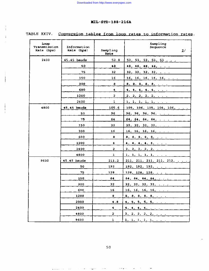
5.2.9.1 Multisaml inq. The multisampling technique shall beused with information rates specified in table XXIV.Multisampling shall not be used in conjunction with bit stuffingor FEC.
5.2.9.1.1 Bit framlnq.
. In this mode of operation, all bits(data and idle) shall be transmitted using the information rateclock, that shall be derived from the loop rate clock accordingto the sampling sequences shown in table XXIV. This shall ensurethat information bits contained in the loop rate data streambetween the transmitter and receiver have a fixed and knownrelationship to the loop bits.
5.2.9.1.1.1 Start-fltoD data . The DA and MS shall only transmitan integral number of stop bits. For International Alphabet No.2 (IA No. 2) start-stop code, one start, five data, and at leasttwo stop bits (eight unit IA No. 2 code) shall be transmitted.In all cases, if there are no characters available fortransmission, an integral number of info-tion bit times ofmarks shall be generated before starting the next character.
5.2.9.1.1.2 9~ ~ta izinq information bite. When the message rateto loop rate transformation results in a fractional number ofloop samples per information bit, the fractional loop bit shallbe rounded to an integral number by addition or subtraction ofthe fractional unit in a manner such that the average infomnationrate is maintained (see figure 4 and table XXIV) .
5.2.9.1.2 JUon-bit franunq,
In this mode of operation, allinformation (data and idle~ transmitted shall be multisampled atthe loop clock rate i.e., bit framing (5.2.9.1.1) and bitquantization (5.2.9.1.1.1) need not be performed.
5.2.9.1.3 Reconstruct ion of multisam led data The receivershall reconstruct the data that has been transmitted by means ofmultisampling.
5.2.9.2 Bit Stu ffinq. Bit stuffing shall be utilized to adjustcertain information rates to loop rates (see table XXIV andAppendix D, table XXVIII). Bit stuffing shall be accomplished bytransmitting three data bits followed by two stuff bits. If FECis used, bit stuffing shall be accomplished subsequent to FEC.
NOTE : The receiver must be aware that the relationship of stuffbits to the FEC code word may not have a fixed relationship.
5.2.9.3 Automatic ReDea t-Reaues t (ARo) . ARQ is an errordetecting scheme used by Mode I, Mode V, Mode VI, and Mode VII.A.RQ may be used in conjunction with FEC and multisampling.
49
Downloaded from http://www.everyspec.com
MIL-STD-188-216A
TABLE XXIV.,on tab les fro m 10QD rates to informs tion rates .
I
TransmissionRate (bps)
2400
4800
9600
SamplingInformation SequenceRate (bps) Sqling ~/
Rate
45.45 bauds 52.8 52, 53, 53, 53, 53 . . .
50 I 48 I 48, 48, 48, 48, . . .
75 32 32, 32, 32, 32, . . .
150 16 16, 16, 16, 16, 16, . . .
600 4 4, 4, 4, 4, 4, . . .
1200 2 2, 2, 2, 2, 2, . . .
2400 1 1, 1, 1, 1, 1, . . .
45.45 bauds 105.6 105, 106, 105, 106, 106, . . .
50 96 96, 96, 96, 96, . . .4
75 64 64, 64, 64, 64, . . .
150 32 32, 32, 32, 32, . . .
300 X6 16, 16, 16, 16, . . .
600 8 8, 8, 8, 8, 8, . . .
1200 4 4, 4, 4, 4, 4, . . .
2400 2 2, 2, 2, 2, 2, . . .
4800 1 1, 1, 1, 1, 1, . - .
45.45 bauds 211.2 211, 211, 211, 211, 212, . . .
50 192 192, 192, 192, . . .
75 128 128, 128, 128, . . .
150 64 64, 64, 64, 64, . . .
300 32 32, 32, 32, 32, . . .
600 16 16, 16, 16, 16, . . .
1200 8 8, 8, 8, 8, 8, . . .
2000 4.8 4, 5, 5, s, 5, . ● .
2400 4 4, 4, 4, 4, . . .
4800 2 2, 28 2, 2, 2, . . . 1
9600 1 1, 1, 1, 1, 1, . . .
50
- - - — — -—— _~_ —– —& 4 w
Downloaded from http://www.everyspec.com

MIL-ST’D-188-216A
TABLE XXIV. Conversion tables from loop rates to ~form@ion rates -,
Continued.
LoopTransfnissionRate (bps)
16000
32000
InformationRate (bps)
45.45 baudB
50
75
150
300
600
1200
2400
4800
9600
2000
4000
8000
16000
45.45 bauds
50
75
150
300
600
1200
2400
4800
9600
2000
4000
8000
16000
32000
SamplingFUste
352.0
320
213-1/3
106-2/3
s3-1/3
26-2/3
13-1/3
6-2/3
3-1/3
Stuffed to16000
8
4
2
1
704.1
640
426-2/3
213-1/3
106-2/3
53-1/3
26-2/3
13-1/3
6-2/3
3-1/3
16
8
4
1
SaqlingSequence
~/
352, 352, 352, 352, . . -
320, 320, 320, 320
213, 213, 214, . . .
106, 107, 107, . . -
53, 53, 54, 53, 53, 54, - - .
26, 27, 27, . . .
13, 13, 14, . . ●
6, 7, 7, 6, 7, 7, . - .
3, 3, 4, 3, 3, 4, . . -
3+2, 3+2, 3+2, . . . M
8, 0, 8, 8, 8, . . .
4, 4, 4, 4, 4, . . .
2, 2, 2, 2, 2, . - .
1, 1, 1, 1, 1, . . -
704, 704, 704, 704, 704, 704,704, 704, 704, 705, . . .
640, 640, 640, . . .
426, 427, 427, . . .
213, 213, 214, . . .
106, 107, 107, . . .
53, 53, 54, . . .
26, 27, 27, . . .
13, 13, 14, . . .
6, 7, 7, 6, 7, 7, . . .
38 3, 4, 3, 3, 4, . . .
16, 16, 16, . . .
0, 0, 8, 8, . . . 4
4, 4, 4, 4, 4, - . .
2, 2, 2, 2, 2, . . .
1, 1, 1, 1, 1, . . .
&/ 3+2 = 3 data bits plus 2 stuff bits 22. . .; repeat previous sequences
51
Downloaded from http://www.everyspec.com
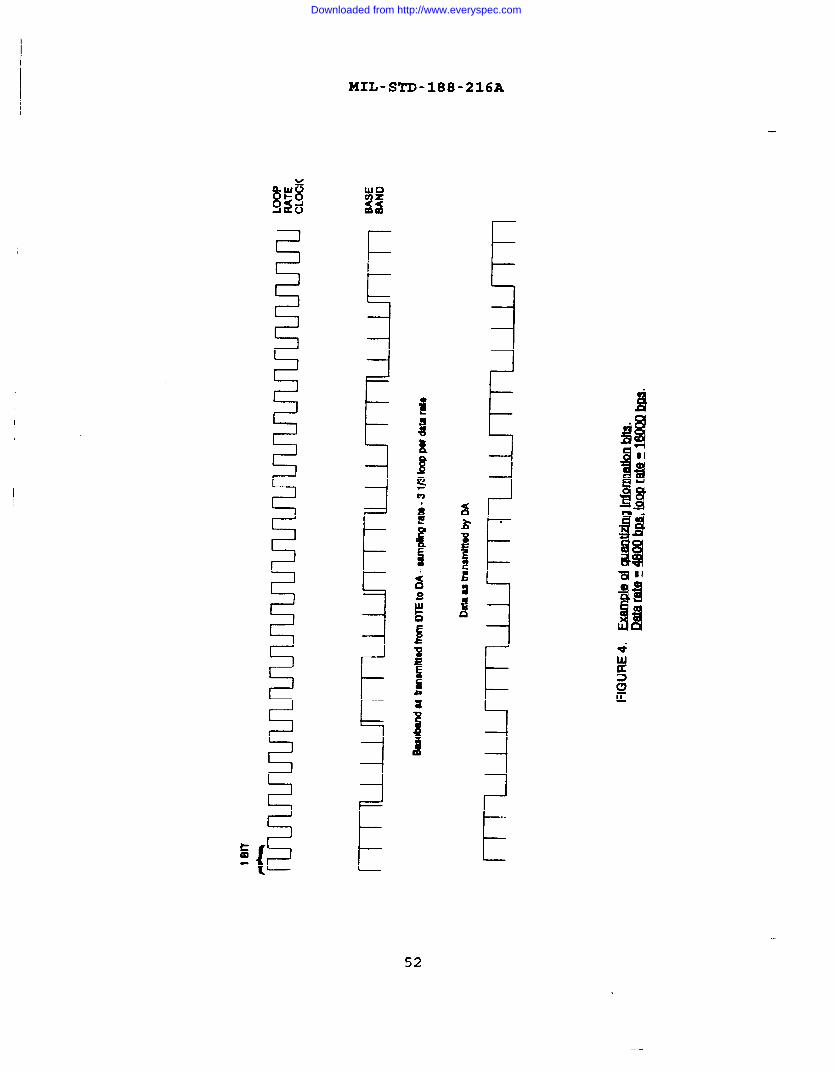
MIL-STD-188-216A
I
52
.
11
Downloaded from http://www.everyspec.com
XIL-STD-188-216A
5.2.9.4 Forward Error Corr ectinq (FEC) . FEC specified in thisstandard is 1/2, 1/4, and 1/8 rate Golay (see Appendix D) .
5.3. .
hroutlon.. ,
tme,
chronl~n. and -ou~
5.3.1 s~c hronization seau ences. Synchronization is the processwhereby a transmitter/receiver sharing a connection,cooperatively progresses from a common starting point to acommonly desired end state. During the stages ofsynchronization, a receiver shall utilize the incoming encodedcharacters (e.g., DC4, ESC, and SYN) to achieve synchronization(encoded by multiaampling, bit stuffing, and FEC encoding asapplicable) . During the various synchronization processes (seeAppendix C) , an initiator/responder relationship shall be used todetermine the synchronization leader/follower respectively. Thetypes of synchronization are multisampling, bit stuffing withoutFEC encoding, bit stuffing with FEC encoding, FBC without bitstuffing, and character synchronization. _les of some
typical character synchronization sequences are contained in thetables listed below.
Generation of break, return to idle - table XXI.Normal call termination - table XXII.Change of call characteristics - table XXIII.Call initiation - table XXV.Reject message - table XXVI.Transmission complete, return to idle - table XXVII.Invalid characteristics - table XXVIII.
5.3.1.1 Multisanmlinq When multisampling is employed, thetransmitter shall send-the current SYN character encoded withmultisampling. The receiver shall establish bit synchronizationon the information rate bits of the SYN pattern. The respondershall declare itself ‘in sync” upon detection of four contiguousdecoded sync characters.
5.3.1.2 Bit stuffinq without FRC encodmq,
The initiator,having attained synchronization, shall send ESC characters withstuff bits and data bits positioned as shown in figure 5. Theresponder shall strip stuff bits from the incoming bit streamusing the previously acquired frame synchronization. Theresponder shall declare itself ‘in sync” upon detection of fourcontiguous decoded ESC characters.
5.3.1.3 B-it stuffina with FEC encodinq. The initiator, havingattained synchronization, shall send FEC encoded ESC characterswith stuff bits, data bits, and FEC code bits positioned asrequired by Appendix D for Golay coding. The responder shalldeclare itself “in sync” upon detection of four contiguousdecoded ESC characters.
NOTE : The receiver must be aware that a fixed relationship maynot exist between stuff bits and the FEC code word.
53
Downloaded from http://www.everyspec.com

,
MIL-STD-188-216A
54
Downloaded from http://www.everyspec.com

i
HIL-STD-188-216A
.
Ii!.11
I.9
9.
Ii!....Ela
Ii.$!3m~
KD
9
55
Downloaded from http://www.everyspec.com
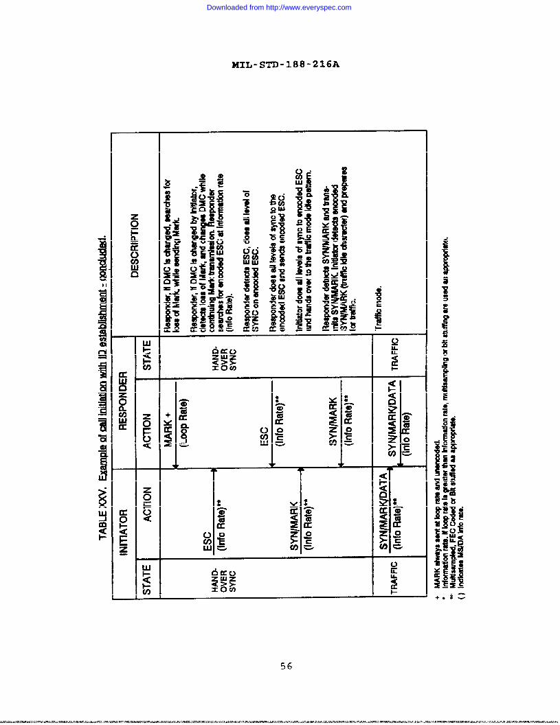
MIL-STD-188-216A
‘a
!.$Ymg
56
Downloaded from http://www.everyspec.com

MIL-STD-188-216A
aUJ0zRVIUJu
I
57
Downloaded from http://www.everyspec.com

lKIL-STD-188-216A
.-
.
o‘E=
58
Downloaded from http://www.everyspec.com

MIL-STD-188-216A
KwnzRu)U9Ju
u
~en
●
Oxt)202< >sx m
x0uo
oE=
59
Downloaded from http://www.everyspec.com
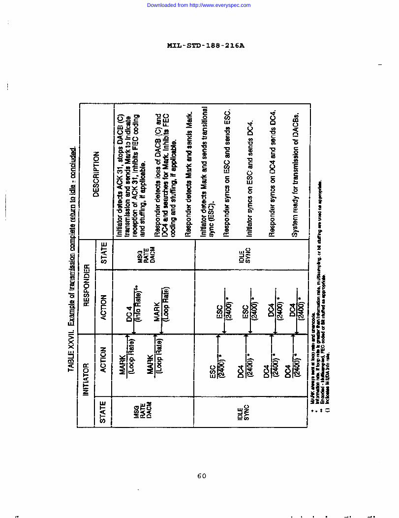
MIL-STD-188-216A
1
us003wc0
.ti
g
n
#g—
—
60
—
Downloaded from http://www.everyspec.com

MIL-STD-188-216A
61
Downloaded from http://www.everyspec.com

MIL-STD-188-216A
62
Downloaded from http://www.everyspec.com
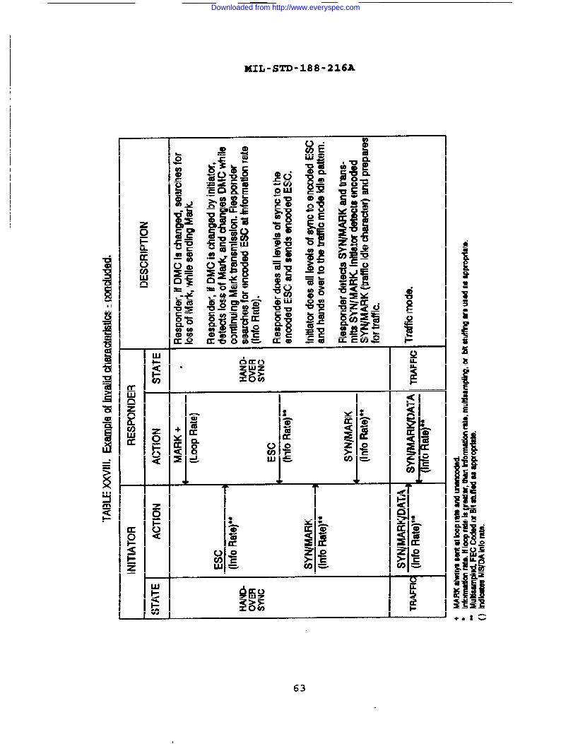
MIL-STD-188-216A
I
f
.
f!
+Oa=
63
Downloaded from http://www.everyspec.com
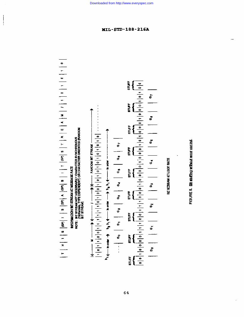
MIL-STD-188-216A
o
\{-
0
0
0
l!{–00I
T ‘I,I,I
,
I
<
UJ
a
*
1-
${–000
9*
00m.00
2{–00T0
.
& —
${–00
t k -r6{–0
xs I
I1t-
a“
64
Downloaded from http://www.everyspec.com

MIL-STD-188-216A
5.3.1.4 FEC encodinq without bit stuffinq. The initiator shallsend FEC encoded ESC characters (1/2 rate~ 1/4 rateg or l/8 rate)as required by Appendix D for Golay coding. The responder shalldeclare itself “in sync” upon detection of four contiguousdecoded ESC characters.
5.3.1.5 character WX@&r oni~~ ion A DA/MS shall obtaincharacter synchronization by searching the decoded informationrate bit stream, bit by bit for an eight-bit pattern thatcorresponds to the current SYN character. Upon finding a match,the DA/MS shall tentatively establish character boundarysynchronization and then examine the next three characters andensure that they are also the SYN character. If SO, charactersynchronization shall be considered acguired. If any one of thethree characters is not the current SYN character, the entireprocess shall be initiated again starting with the bit-by-bitsearch of the encoded information rate bit stream. The detailedsynchronization requirements are given in Appendix C.
5.3.2 Loss of $3Vnchronization and resvnchron ization. Uponhaving progressed through many levels of synchronization to adesired level, it is then possible for any one of those levels ofsynchronization to be lost. The means for detecting loss ofsynchronization are described h Appendix C.
5.3.2.1 Methods for detect inq loss of Svnc hron ization. Themethods for detecting loss of synchronization shall be by:
a. Excessive unexpected characters (in a mode where suchrecognition is possible) .
NOTE: A hand.back request shall not be treated as excessiveunexpected characters.
b. Excessive start/stop bit position errors (Modes II orv).
co Failure to progress to the next state of DACM.
d. Excessive parity errors in traffic state.
e. The operator.
5.3.2.2 Recoven? nrocedure~ Recovery procedures shall rangefrom simple operator alarms with manual recovery to automaticlink synchronization including automatic message cancellation andretransmits ion. The general capabilities provided by the DACMprotocol are specified in Appendix C. For all recoveryprocedures other than a character resynchronization, the DA/MSshall verify loss of synchronization before attempting recoveryprocedures.
65
Downloaded from http://www.everyspec.com

MIL-STD-188-216A
5.3.3 Time-out. ‘X’MeDA/MS shall time-out when spchronization, ‘-signaling and traffic procedures are not executing properly aftera predetermined lapsed time. Timers shall be implemented asdescribed in table XXIX and Appendix C.
NOTE: Timers/time-Outs tolerances are to be specified by thedeveloper of the DA.
5.3.3.1 ~ececknce w“, ●
traff~,
Forcircuit switched high precedence traffic, the DA/MS still returnto idle rate and institute recovery procedures by sending a Breaksequence (see 5.2.7 and Appendix C) .
5.3.3.2 Ci rcuit switched with low ~reced~ce traf~,
Forcircuit switched low precedence traffic, the DA/MS s&l releasethe connection.
5.3.3.3 pedi~ted tr-,
For a dedicated circuit, the DA/MSshall return to the idle ;ate and institute recovery proceduresby sending a Break sequence (see 5.2.7 and Appendix c).
5.4 st~ctu ral validation of DACB. The DA/MS shall validate theDACB using the following rules (see figure 2) .
a. The five framing characters shall be validated (STX,31, EM, ETX, and BP).
b. Each identifier character shall be checked for parityerror.
c. Position 13 of the DACB shall be validated anddepending upon the character present, additionalpositional character content validation shall beperformed.
5.5 ODeration with cm toqraQ hic eau iDmenC
5.5.1. ,
on~loq Loss of cryptographicsynchronization and its recovery is a ;Ubset of overall loss ofsynchronization and respchronization (see 5.3.2) .
5.5.2 Pata mo~ (DMC) . Data transmission betweentransxnitter/receiver shall be capable of operating with orwithout the DMC of the associated COMSEC equipment enabled.Changing of the DMC status shall be accomplished during handoversynchronization. For circuit switched data calls the DMC shallbe enabled before entering the idle synchronization state.
5.5.2.1 ~.
On dedicated lines, the status of DMCduring the connection shill be pre-coordinated by the operators.
—
x,.
66
Downloaded from http://www.everyspec.com

MIL-STD-188-216A
TABLE XXIX. Timeouts a d t eOUt nsn im actio .
STATE CONDITION ACTION TO BE TAXRN
lkny synchronization 10 seconds no . Send break if
character synchronization dedicated
established received ● Send break if CSand highprecedence
● Terminate call if
CS and 10W
precedence
DACB sent 10 second no ● send break ifresponse dedicated
● Send break if CSand highprecedence
● Terminate call ifCS and lowprecedence
WBT 31 received 10 second time out Resend DACB
5 minute time out Alarm
WBT 31 sent 3 seconds and not Resend WBT 31able to validate sequenceDACB
Break sent 10 second time out ● Send break ifdedicated
● Send break if CSand highprecedence
. Terminate call ifCS and lowprecedence
MARK sent 10 second time out . Send break ifdedicated
● Send break if CSand highprecedence
. Terminate call ifCS and lowprecedence
67
Downloaded from http://www.everyspec.com

MUL-STD-188-216A
5.5.2.2 ~d~ ●
. During call connection using DACBS, the -associated COMSEC equipment of the DA/MS shall utilize the DMCfeature. The successful transmission of a DACB (NUL) shallestablish the state of DMC as specified by the identifiercharacters in position 15 of the DACB. Once the state of the DMCis determined by the first DACB (NUL) , the state of the DMC shallbe fixed until the call is terminated.
5.6 Glare. A glare situation arises when both partiessimultaneously attexnpt to initiate DACB signaling. In such acase, the master’s signaling shall be allowed to succeed (masterwins glare) and the slave shall back down (lose glare) and shallrespond to the master’s signaling.
5.7 er charact ers. Whenever the characteristics of aDACB are changed during call initiation, the DA upon completionof the. call, shall reset the DACB characteristics to thoseidentified during DA setup.
I
NOTE : The setup and manner of choosing the DACB characteristicsshall be specified in the procurement documentation.
68
Downloaded from http://www.everyspec.com
MIL-STD-188-216A
6. INFORMATION FOR GUIDANCE ONLY
6.1
datadatadatadatadata
Subject te rm (key word ) listinq
adapt eradapter control blockadapter control modeadapter termination unitmode control
error detectiongolay code
6.2 ~ec~ c?~e~any of the DACM S&is not using one of
Mode:: Mode
Mode:: Modee. Modef. Mode
I,II,II,v,v,VI,
The DA/MS shall not searchcharacters (ESC,DC4) , whenthe following Modes/Codes:
IAIAIA1A
No.2,No.5,no.2,No.5,
Odd
Odd
Parity,
Parity,
forthe
or act uponData Adapter
6.2.1 Circuit switched.
comectlons . Upon completion of traffictransmission, the initiator/master shall terminate the call byreleasing the connection (hang-up) . For all other recoverysituations see 5.3.3.1 and 5.3.3.2.
6.2.2 Handback. Handback shall be accomplish by the transmissionof a Break sequence.
69/70
I A f I n 1 n 1 A I I n f I [1 i I --- J * f I . / J n I -i / I n
Downloaded from http://www.everyspec.com

MIL-STD-188-216A
(This page intentionally left blank.)
Downloaded from http://www.everyspec.com

MIL-STD-188-216A
APPENDIX A
DUPLEX MESSAGE PROTOCOL
Appendix A contains specific information in support of DuplexMessage Protocol (Generic Gateway) . Appendix A is not amandatory part of this-document. Implementation of the DuplexMessage Protocol is optional, but when implemented, it shall beaccomplished in accordance with this appendix, (Appendix A)
~.—--—-—--~~=<=_.=—=.—_.—==>>._._.-.
71
Downloaded from http://www.everyspec.com

MIL-STD-188-216A
APPENDIX A
10. FUNCTIONAL DESCRIPTION
The Full Duplex Message Protocol (FD~) is used byapplication programs (gateway tasks) to send and receive messagesbetween two message handling systems. An application programreads messages from a mass storage device (disk) and utilizesFDMP to transfer them to another system. FDMP passes messages ithas received from another system to the application program whichwrites them to disk. FDMP utilizes a link level protocol totransfer messages and control information between systems.Specific features of FDMP are:
● ~erates in a full duplex mode. That is, sending andreceiving of messages may occur simultaneously.
● Control of the send and receive functions isindependent. Message transfer in one direction may besuppressed without affecting transfer in the otherdirection.
● Supplemental data, such as dissemination information,may be transferred with the message text.
● FDMP is independent of the link level protocol, deviceinterface, and physical characteristics of the link.
● Start up and shut down of either side of the link isasynchronous w“ith respect to the other side.
To fully utilize FDMP, a link level protocol such as DigitalData Communications Message Protocol (DDCMP) or High-level DataLink Control (HDLC), which supports full duplex, varitile sizedblocks , and error detection and recoveryt should be USed” TOallow for character oriented protocols such as Bisync to be used,FDMP avoids the use of binary data and communication controlcharacters.
FDMP assumes a point-to-point communication environment andcontains no provisions for use in a network or multipointenvironment.
20. INTERFACES
This section describes the relationship between the userapplication, FDMP, and the link level protocol/device interface.
20.1 JJpDlicat ion inte rface to FDMP. FDMP shall accept messagesegments from the application program. The application programidentifies the first and last segments. FDMP is responsible foraddincx its control headers and breaking down and/or combiningthose-segments into buffers of the size it usestransfer. FDMP shall pass segments of messages
72
for datait has received,
Downloaded from http://www.everyspec.com
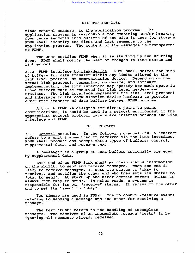
MIL-STD-188-216A
minus control headers, to the application program. Theapplication program is responsible for combining and/or breakingdown those segments into buffers of the size it uses for storage.FDMP shall identify the first and last segments to theapplication program. The content of the messages is transparentto FDMP.
The user notifies FDMP when it is starting up and shuttingdown . ~W shall notify the user of changes in link status andlink errors.
20.2 FDMP interface to Lmkldevlce* .
FDMP shall select the sizeof buffers for data transfer within”-y limits allowed by thelink level protocol or communication device. Depending on theactual link protocol, communication device, and softwareimplemental ion, the link interface may specify how much space inthose buffers must be rese~ed for link level headers andtrailers. The link interface implements the link level protocoland interface to the communication device hardware to provideerror free transfer of data buffers between FDMP modules.
Although FDMP is designed for direct point-to-pointcommunications, it could be used in a network environment if theappropriate network protocol layers are inserted between the linkinterface and FDMP.
30. FORMATS
30.1 General notation. In the following discussions, a “buffer”refers to a unit transmitted or received via the link interface.FDMP shall produce and accept three types of buffers: control,supplemental data, and message text.
A ‘message” is a group of text buffers optionally precededby supplemental data.
Each end of an FDMP link shall maintain status informationon the ability to send and receive messages. When one end isready to receive messages, it sets its status to “okay toreceive, , and notifies the other end who then sets its status to‘okay to sendm. At start up and after certain errors, status isalways ‘not okay to sendn. In other words, a system isresponsible for its own “receive” status. It relies on the otherend to set its “send” to “okay”.
Two timers are used in FDMP. One to control/measure eventsrelating to sending a message and the other for receiving amessage.
The term ‘bust” refers to the handling of incompletemessages. The receiver of an incomplete message “busts” it byignoring all segments already received.
73
Downloaded from http://www.everyspec.com

MIL-STD-188-216A
The term “re-queue W refers to the handling of incompletemessages by the sender. When the sender “re-queues” a message,he saves it for retransmission at a future time.
Two sets of message numbers are maintained by both ends ofthe link, one for each direction of transfer.
The term M/S refers to the sender of a message and M/R thereceiver. The terms ‘senderm and ‘receiver” refer respectivelyto the sender and receiver of buffers.
ASCII numeric fields always have the most significant digitfirst and are padded with leading zeros when necessary.
30.2 control buffe r~. Control buffers are used to communicatestatus and control the flow of messages. The foxmat of a controlbuffer shall be as follows:
i--i- -i--i-i-i-ii-i--i--i-i-i-i-i-i- ‘-- - - - i----- ----- ----- ----- ----- ----- ----- ---- ---where:
c 1 byte, ASCII ‘C’ (103 octal) - type identifierfor control buffer.
MSGNO 4 bytes, ASCII numeric - number of the message towhich the control buffer applies.
SUBTYP 3 to 6 bytes, ASCII - control subtype.
The control subtypes are the following:
REQSTS Request status. FDMP shall send REQSTS at startup and after any error indicative of loss ofcommunications. The senders status is ‘not okayto aendm.
READY
WBT
Ready to receive messages. When ready, FDMP shallsend READY in response to REQSTS. The senderstatus is ‘okay to receive~. The receiver statusbecomes ‘okay to send”.
Wait before transmitting (i.e., not ready toreceive) . FDMP shall send WE3T in response toREQSTS when not ready, or to indicate change inready to receive status to not ready. Sendersstatus is “not okay to receive”. Receivers statusbecomes “not okay to send’ . When sent whilereceiving a message, it indicates that the M/Rcannot accept the complete message. The M/R“busts” the message. Upon receipt of WET, the M/Sshall stop sending and re-queue the message. The
74
Downloaded from http://www.everyspec.com
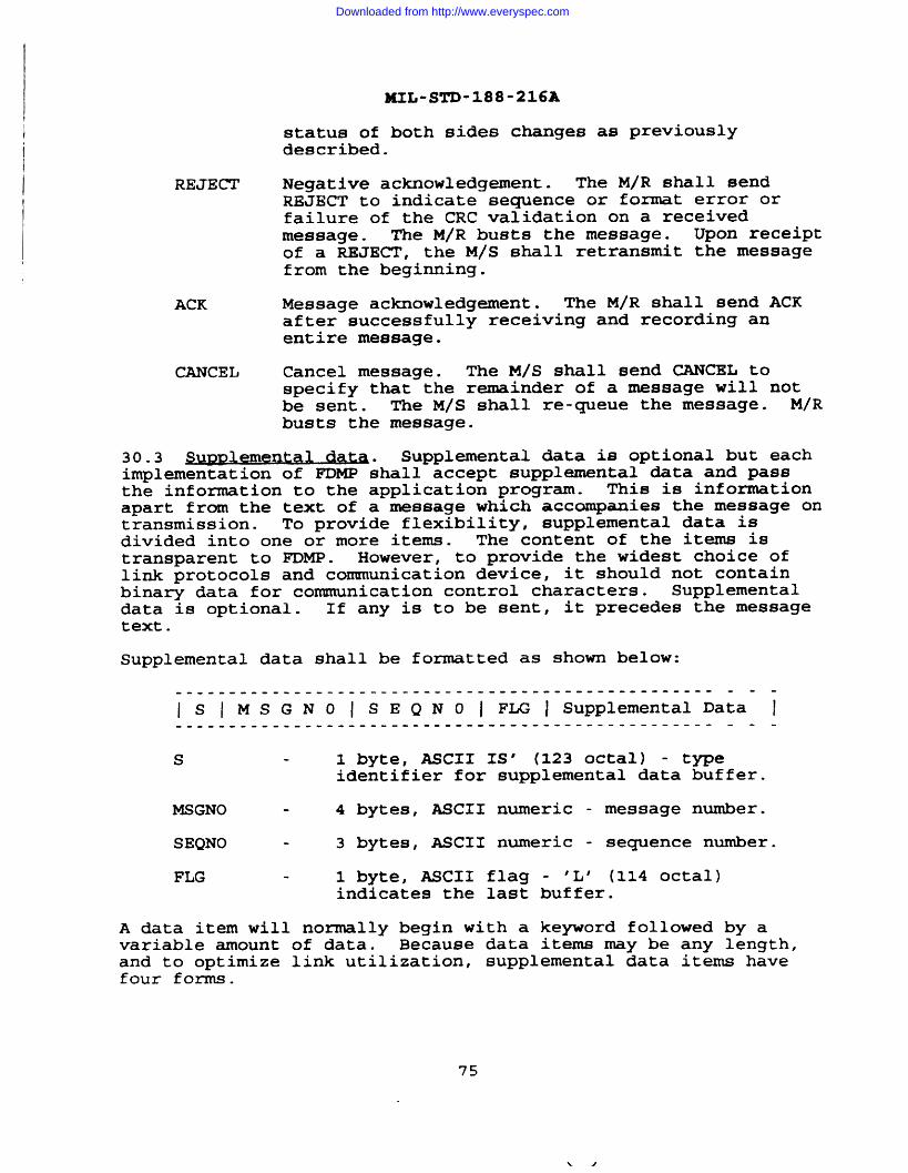
i
I
BUL-STD-188-216A
status of both sides changes as previouslydescribed.
REJECT Negative acknowledgement. The M/R shall sendREJECT to indicate sequence or format error orfailure of the CRC validation on a receivedmessage. The M/R busts the message. Upon receiptof a REJECT, the M/S shall retransmit the messagefrom the beginning.
ACK Message acknowledgement. The M/R shall send ACKafter successfully receiving and recording anentire message.
CANCEL Cancel message. The M/S shall send CANCEL tospecify that the remainder of a message will notbe sent. The M/S shall re-queue the message. M/Rbusts the message.
so-s ~= Supplemental data is optional but eachimplementation of FDMP shall accept supplemental data and passthe information to the application program. This is informationapart from the text of a message which accompanies the message ontransmission. TO provide flexibility, supplemental data isdivided into one or more items. The content of the items istransparent to FDMP. However, to provide the widest choice oflink protocols and communication device, it should not containbinary data for communication control characters. Supplementaldata is optional. If any is to be sent, it precedes the messagetext.
Supplemental data shall be formatted as shown below:
s 1 byte, ASCII IS’ (123 octal) - typeidentifier for supplemental data buffer.
MSGNO - 4 bytes, ASCII numeric - message number.
SEQNO - 3 bytes, ASCII numeric - sequence number.
FLG 1 byte, ASCII flag - ‘L’ (114 octal)indicates the last buffer.
A data item will normally begin with a keyword followed by avariable amount of data. Because data items may be any length,and to optimize link utilization, supplemental data items havefour forms.
75
Downloaded from http://www.everyspec.com

MIIJ-STD-188-216A
Form 1 is used when an item fits in one buffer.
----- ----- ----- ----- ----- ---- ---- ----- ----II L E N I Ke~ord, Data I Additional- ~~e=- -j----- ----- ----- ----- ----- ---- ---- ----- -- ----- ----- -
LEN 3 bytes, ASCII numeric - length ofthe data item.
Additional items Optional. If present, they will beFoxm 1 or 2.
Form 2 is used when the beginning of an item is too large to fitin the remaining buffer space.
i--i-- i--i-- i-- O--i--ii&iX-iii~- - - - - i----- ----- ----- ----- ----- ----- ----- --- -000 - 3 ASCII zeros - signifies that the remainder of
the buffer contains the beginning of the item.
Form 3 is used for the continuation of an item which fills theentire buffer.
i--~ --~-- ~--i --~-- i--D~------ - - - - - ,----- ----- ----- ----- ----- ----- --- -
000 - 3 ASCII Zeros - signifies that the entire buffercontains the continuation of the item.
Form 4 is used for the last segment of an item which spansbuffers.
---
j--i-i-i-- ii&iid;iiiiiiii--- - - i--~~d~~Q~:~-~~~- I----- ----- ----- ----- ----- ----- ---- --- ----- ----- ----- --
LEN
Additional items
3 bytes ASCII - length of the lastsegment of the data item.
Optional. If present, they will beForm 1 or2.
..
—
76
Downloaded from http://www.everyspec.com

—
BHL-STD-188-216A
30.4 MesSa ae text. The fozmat of message text buffers is:
..-
i-i-i -i-i-i-iii ----------- ‘-------------------- -S E Q N O ~ FLG ~ Message Text I---- ---- ---- ---- ---- ---- ---- ---- ---- ---- ---- ---- --- --
where
T 1 byte, ASCII ‘T’ (124 octal) - typeidentifier for message text buffers.
MSGNO - 4 bytes, ASCII numeric - message number.
SEQNO - 3 bytes, MCII nueric - sequence number.
FLG I byte, ASCII flag - ‘L’ (114 OCtal)indicates the last buffer.
The content of the message text is transparent to FDMP. However,
it should not contain binary data nor communication controlcharacters.
40. OPERATION
FDMP is a true full duplex protocol with respect to sendingand receiving messages. Operations involving sending a messageand receiving a message have no effect on each other. Therefore,control buffers have meaning only to message transfer in a givendirection. REQSTS and CANCEIJ are always sent by the messagesender (M/S) to the message receiver (M/R) . READY, WBT,REJECT,and ACK are always sent by the M/R to M/S.
FDMP operation for both sending and receiving are dividedinto four modes: not ready, starting up (becoming ready) 8 idle(ready but inactive), and actively sending or receiving.
40*1 ~* For each mode the following paragraphsgive events that may occur and the subsequent action that is to betaken.
40.1.1 ~ This mode is entered if the applicationprogram is suppressing message transmission. In this mode, FDMPshall inhibit sending any buffers and shall ignore READY, WBT,ACK, and REJECT. The status remains ‘not okay to sendw .
40.1.2 ~tartu~. When starting up, or after a link error, thestatus is “not okay to sendrn. The status of the other end must bedetermined. FDMP shall send the REQSTS control buffer and start atimer. One of the following will then occur:
● Control READY is received. FDMP shall cancel the timerand change status to ‘okay to send”. If messages arewaiting, transmission may begin. FDMP shall enter idleor active mode.
77
WJ
Downloaded from http://www.everyspec.com

HIL-STD-188-216A
● Control WBT is received. FDMP shall restart the timerand retain the status of ‘not okay to sendn. FDMP shall ‘-remain in startup mode.
● Timer emires. FDMP shall retransmit the REQSTS controlbuffer =d the restart the timer. A counter isincremented. When the counter reaches its thresholdvalue, an error message is printed and the counterreset. FIX@ shall remain in startup mode.
● ACK or REJECT received. Incrementcount and check error thresholds.startup mode.
40.1.3 ~dl~. When no message is being sentoccur:
appropriate errorFDMP shall remain
the following my
,. Control WBT is received. FDMP shall start the timerset status to ‘not okay to send”. FDMP shall enterstartup mode.
● Control READY is received. This buffer is ignored.FDMP shall remain in idle mode.
o ACK or REJECT received. Increment appropriate errorcount and check error thresholds. FIX@ shall remainidle mode.
● A message ready to be sent. FDMP shall enter themessage active mode.
in
and
in
40.1.4 Message act iv?. Sending a message consists of transmittingbuffers of supplemental data and text and waiting foracknowledgement after the last buffer is sent. When sending amessage, one of the following may occur:
● Control REJECT is received. After any buffers in theprocess of transmission are complete, FDMP shallretransmit the entire message, including supplementaldata. The same message number is used. Re-sequencingbegins at 001. Increment appropriate error count andcheck error thresholds. FDMP shall remain in messageactive mode.
● Control WBT is received. Further transmission ofbuffers for the message shall be inhibited. FDMP shallre-queue the message and change status to ‘not okay tosendW . The timer is started. FDMP shall enter thestartup mode.
● Control READY or ACK is received. Increment appropriateerror count and check error thresholds. FDMP shallremain in message active mode.
.-
78
Downloaded from http://www.everyspec.com

KXL-STD-188-216A
● Link error occurs. FDMP shall attempt to send controlCANCEL and proceed as though receiving WBT.
● User message handling error occurs. ~MP shall sendcontrol CANCEL and enter idle mode. The u~er programdetermines whether message is to be retransmitted.
After sending the last text buffer, FDMP shall start a timer. Atthis point the following may occur:
● Control ACK is received. FDMP shall cancel the timer. Ifany messages are available, ~~ may begin sending.Otherwise, FDMP shall enter the idle mode.
● REJECT or WBT is received. FDMP shall cancel the timer.Further transmission of buffers for the message shall beinhibited. FDMP shall re-queue the message and changestatus to ‘not okay to aendn . The timer is started.FDMP shall enter the startup mode.
● Timer expires. FDMP shall send CANCEL and re-queue themessage. Status becomes ‘not okay to send”. FDMP shallenter startup mode.
● Control READY received. Increment appropriate errorcount and check error thresholds. FDMP shall remain inmessage active mode.
40.2 Rece ivinq Messaqes . For each mode the following paragraphsgive events that may occur and the subsequent action that is to betaken.
40.2.1 Not readv. Status is “not okay to receive”. FDMP shallsend a control WBT in response to supplemental data, messagetext, control CANCEL, or REQSTS buffers.
40*2*2 iwK!2JQ* status becomes “okay ‘0 receive”” FDMP shallsend a control READY and enter idle mode.
40.2.3 Idle. When “okay to receive, and no message is beingreceived the following may occur:
● REQSTS is received. FDMP shall send a control READY andremain in idle mode.
● Data or text with sequence number 001 is received. FDMPshall enter message active mode and start a timer.
● Data or text with sequence number not 001 is received.FDMP shall send control REJECT and remain in idle mode.Increment appropriate error count and check errorthresholds.
79
Downloaded from http://www.everyspec.com

MIL-STD-188-216A
● Control CANCEL is received. Increment appropriate errorcount and check error thresholds. FDMP shall remain in _idle mode.
40.2.4 Mess aqe active. While receiving a message the followingmay occur:
● Good data or text is received. Increment count of goodbuffers. If the last text buffer of a message isreceived, FDMP shall cancel the timer and enter idlemode. Otherwise, FDMP shall remain in the messageactive mode.
● Control CANCEL is received. Bust the message. FDMPshall send control READY and enter idle mode.
● Timer expires. If the good buffer count is non-zero,FDMP shall remain in the message active mode. Restartthe timer and reset the count. If the good buffer countis zero, FDMP shall send REJECT and enter idle mode.Bust the message.
● User message handling error occurs. FDMP shall sendcontrol REJECT or WBT and enter idle or not ready modeas directed by the user program.
40.3 Shllttina down or throttling . FDMP may throttle incomingmessages either as a condition of available buffer space or upondirection of the application program. FDMP shall send a controlWBT to stop receiving messages. If a message was being received,it is busted.
50. A TYPICAL IMPLEMENTATION
A typical environment includes the Communication SupportProcessor (CSP) as used by the All Source Analysis System (=N).The CSP provides all external interfaces including the interfaceto AUTODIN. The CSP uses a communications interface processorcalled the Communications Protocol Processor (CPP) to standardizeall external interfaces. For purposes of this document, the termCSP will be used to refer to the combined CSP and CPP. The fullduplex Message Protocol (FDMP) is used for message transferbetween the CSP and other processors. The link level protocolused is the Digital Data Communications Message Protocol (DDCMP) .The format of message text sent from the CSP and accepted by theCSP is either DOI-103 or JANAP 128.
50.1 ~ Flow~ Data flow between the CSP and external systemsis full duplex. ● A typical message exchange scenario between tofull-duplex FDMP/DDCMP modules is diagramed in below:
CSP requests DDCMP synchronization with DDCMP STRTREMOTE receives STRT and responds with DDCMP STACK(DDCMP link between CSP to REMOTE is initialized)
—
80
..—.- . ——_ _ . ___ _ _ . — -—— , ,,.,q , T \
Downloaded from http://www.everyspec.com

MIL-STD-188-216A
REMOTE requests FDMP synchronization with FDMP REQSTSCSP receives REQSTS and responds with FDMP READY with DDCMP ACKREMOTE receives READY and returns DDCMP ACK(FDMP link from REMOTE to CSP is initialized)CSP reguests FDMP synchronization with FDMP REQSTSREMOTE receives REQSTS and responds with FDMP READY with DDCMP ACKCSP receives READY and returns DDCMP ACK(~~ link from CSP to REMOTE is initialized)CSP transmits FDMP message to REMOTEREMOTE receives message and detects CRC error in DDCMP HeaderREMOTE sends DDCMP NAKCSP receives NAK and retransmits FDMP messageREMOTE accepts message and transmits message to CSP with DDCMP ACKCSP receives message and returns DDCMP ACK
50.2 Protoc 01 Formats Link level protocol coxmnunications
between the CSP and th; REMOTE occurs at the DDCMP level. TWO~es of DDCMP frames are used in the interface:
● Data Frames
● Control Frames
Control frames are used to communicate link controlinstructions, transmission status and reception status and aredescribed in section 50.2.1. Data Frames are used to transmit andreceive variable length data message and are described in section50.2.2.
The DDCMP Data Frames that are communicated on this interfacealways contain an FDMP frame. The FDMP fames are extracted onreception from, and assembled on transmission to, the RmOTE.
50.2.1 ~ nrlM DDCMP is a protocol whichcarries link control information, tr&smission status, andinitialization notification between the Transmitter and theReceiver. The following control types are used by this protocolimplemental ion:
Start Message - STRT. The STRT message establishes initialcontact and synchronization on a DDCMP link. The transmittersends this message during link start-up or reinitialization.The start sequence resets message numbering at thetransmitter and receiver.
Start Acknowledge Message - STACK. The STACK message is theresponse to a STRT message. It tells the receiver that thetransmitter has completed initialization.
Acknowledge Message - ACK. This message acknowledges the receiptof correctly numbered data messages that have passed the CRC-16 check. This message is also used to acknowledge receiptof the DDCMP control STACK message. The ACK message is usedwhen acknowledgments are required and when no data messages
81
Downloaded from http://www.everyspec.com

MIIJ-STD-188-216A
are to be sent in the reverse direction. The ACK messageconveys the same information as the RESP field in numbereddata messages.
Negative Acknowledge Message - NAK. The NAK message passes errorinformation from the DDCMP data receiver to the DDCMP datasender. The NAKTYPE field indicates the cause of the error.The NAK message also includes the same information as the ACKmessage. Thus it serves two functions: acknowledgingpreviously received messages and notifying the sender of someerror condition. The following is a list of the possibleerror conditions
BCC Header ErrorBCC Data ErrorRep ResponseBuffer UnavailableReceiver OverrunMessage Too LongHeader Format Error
Reply to Message Number - REP. The REP message requests receivedmessage status from the data receiver. It is usually sentwhen the sender has transmitted a data message and has notreceived a reply within a timeout period. The response to aREP is an ACK or NAK depending on whether the receiver has orhas not received all the messages previously sent by thesender as indicated by the message number in the REP.
50.2.2 ~MP Level C~trol MeRsaqea ~W is used to send andreceive messages between two formatted message handling systems.FDMP assumes a point-to-point communication environment. Theprotocol formats of the FDMP level use the following controltypes:
REQSTS Request status. Applies only to the transmit side.Sent at start-up and after any error indicative of lossof communications.
READY Ready to receive messages. Sent in response to aREQSTS .
REJECT Negative acknowledgement. Sent by the message receiverto indicate a sequence or format error.
ACK Message acknowledgement. Sent after reception of theentire message indicating successful reception and safestore of the message.
---
CANCEL Cancel message. Sent by the message sender to specifythat the remainder of the message will not be sent.
—
82
Downloaded from http://www.everyspec.com

I XIL-STD-188-216A
WBT Wait before transmitting. Sent in response to REQSTS orto indicate a change in receiver’s ability to receivemessages.
50.3 Format Line 15A Ve~fication. The CSP scans DOI-103 andJANAP 128 messages identifying format lines 5, 6, and 12 andcalculates a CRC-16. This value is then converted to ASCII andcompared with the contents of format line 15A. A successfulcomparison will result in continued processing of the message. Ifthe comparison fails, a FDMP REJECT is transmitted indicating theCRC error. The CRC-16 calculation is performed using thefollowing polynomial:
X16 + X13 +.X2 + 1
83/84
Downloaded from http://www.everyspec.com

MIL-S~-188-216A
(This page intentionally left blati.)
Downloaded from http://www.everyspec.com

MIL-STD-188-216A
APPENDIX B
LIST OF ABBREVIATIONS AND ACRONYMS USED IN MIL-STD-188-216
This appendix contains general information in support of MIL-STD-188-216. Appendix B is a nonmandatory part of this document.
I
85
Downloaded from http://www.everyspec.com

Thisusedthis
I
MIL-STD-188-216A
APPENDIX B
ACRONYMS AND ABBREVIATIONS
appendix provides definitions of acronyms and abbreviationsin this standard. This appendix is not a mandatory part ofstandard.
31
ACK
ACP
ARQ
XCII
AUTOD IN
BP
bps
COMSEC
Cs
CTL
DA
DACB
DACB (A)
DACB (B)
DACB (C)
—Control or framing character
Positive acknowledgement
Allied communication publication
Automatic repeat - request
American Standard Code for InformationInterchange
Automatic digital network
Block parity - framing character
Bits per second
Command
Communications
Circuit switch
Control
Data adapter
security
Data adapter control block
DACB with identifier character A inposition 13. Transmission complete -terminate call (GO-ON-HOOK if switched)
DACB with identifier character B inposition 13. Transmission complete -read contents of this DACE3 for newcharacteristics and continue.
DACB with identifier character C inposition 13. Transmission complete -return to idle rate.
.
.-.— ---
Downloaded from http://www.everyspec.com

MIL-ST’D-188-216A
DACB (D)
DACB (DC2)
DACB (E)
DACB (ENQ)
DACB (F)
DACB (G)
DACB (K)
DACB (INV)
DACB (NUL)
DA/MS
DCAC
DC4
DLED
DMC
DACB with identifier character D inposition 13. Cancel all transmissionsince last start of message sequencethen terminate the call (GO-ON-HOOK ifswitched) .
DACB with identifier character ‘DC2’ inposition 13 - reject message-
DACB with identifier character E inposition 13. Cancel reading of DACBcontents for new characteristics andcontinue.
DACB with identifier character ‘ENQ’ inposition 13. Request receiving DA sendits DACB (F) .
DACB with identifier character ‘F’ inposition 13. Positive response toreceived DACB ‘ENQ’ .
DACB with identifier character G inposition 13. Go to voice.
DACB with identifier character K inposition 13. Cryptokey exchange (Futureuse) .
DACB with identifier character ‘INV’ inposition 13. Response when invalid DACBis received.
DACB with identifier character ‘NUL’ inposition 13. Sent during callinitiation.2
Data adapter control mode. This is thestate between DA/MSs in which DACBS maybe sent.
Data adapter/message switch; dataadapter to message switch; between dataadapter and message switch.
Defense Communications Agency Circular
DACM idle character
Dedicated loop encryption device
Data mode control
87
Downloaded from http://www.everyspec.com

MIL-STD-188-216A
DNVT
DO
DODD
DODISS
DOI
DSSCS
DSVT
DTE
DTE -1
DTE -2
DTE -3
EBCDIC
ECP
EFTO
EM
ENQ
ESC
ETX
FDMP
FEC
FED-STD
INFO
INV
IR
Digital non-secure voice terminal
Design objective
Department of Defense Directive
Department of Defense Index ofSpecifications and Standards
DSSCS operating instruction
Defense Special Security CommunicationsSystem
Digital subscriber voice terminal -secure voice/data digital terminal
Data terminal equipment
DTE comected to terminal 1 of DA
DTE connected to terminal 2 of DA
DTE connected to terminal 3 of DA
Extended Binary Coded DecimalInterchange Code
Emergency command precedence
Encrypted for transmission only
End of Medium framing character
Enquiry DACM character
DACM message rate idle character and/oridle synchronization character
End of text - framing character
Full duplex message protocol
Fomard error correction
Federal standard
information
Invalid DACM character
Idle rate
08
Downloaded from http://www.everyspec.com

I
xIL-STD-188-216A
i
IA No. 2
JANAP
LSB
MIL- STD
Ms
MSB
MS/DA
MSG ~TE
N/A
SYN
SYNC
TRI-TAC
WBT
International Alphabet No. 2
Joint Army, Navy, Air Force Publication
Least significant bit
Military standard
Message switch or store and forwardmodule
Most significant bit
Message switchldata adapter
Information rate (Info rate)
Not applicable
character (ESC, DC4)
synchronization
Joint Tactical Communication OfficeEquipment
Wait before transmitting, DACM character
89/90
Downloaded from http://www.everyspec.com

MIL-STD-188-216A
(This page intentionally left blank)
. —
Downloaded from http://www.everyspec.com

HIL-STD-188-216A
APPENDIX C
STATE DIAGRAMS FOR DACM PROTOCOL
Appendix C contains specific information in support of MIL-STD-188-216. Appendix C is a nonmandatory part of this document.
91
--- . . . . , . _= —. — —L—-l 7
Downloaded from http://www.everyspec.com

MIL-STD-188-216A
APPENDIX C
10. GENE-
10=1 ~. The purpose of this appendix is to define theDAm protocol as a tool with many capabilities in a manner whichprovides for a consistent but flexible implementation.
10.2 -. This appendix contains state diagrams illustratingthe DACM protocol. The intent is to clearly define the nomaland abnomal data and control system modes.
20. APPLICABLE DOCUMENTS
Not applicable.
30. DEFINITIONS
For purposes of this appendix, the definitions of section 3 of
this document and FED-STD-1037 shall apply.
40. GENEW4L REQUIR~S
The DACM protocol described herein is general in its nature. It
describes a function which may be implemented within simpleadapter boxes, intelligent terTninals, or large switching centers.
Each of these pieces of equipment have system-level requirementswhich dictate how this protocol is to be implemented. The DACM
protocol function can be subdivided into a set of basic functions(tools, assets, processes) under the control of a “supe~isor”.This is illustrated in figure 6. In the supewisory function,
the “supemisor” will decide how information flows between thesefunctions, what task a given function performs at any given time,and what functions are active at any given time. It is also
responsible for communicating with the higher-level function.
The basic functions are:
a. input bit processing.
(1)
(2)
(3)
(4)
.
Perform serial to parallel conversion.
Perform Golay decoding, bit unstuffin9tdexnultisampling, and framing checking.
Perform input synchronization.
Perform break detection.
92—
Downloaded from http://www.everyspec.com

MIL-STD-188-216A
!5 I
J!!Qa_l-
— ●
co5
r-
1
II
I
I
93
Downloaded from http://www.everyspec.com

HIL-STD-188-216A
b. output bit processing.—
(1) Perfozm parallel to serial conversion.
(2) Perform Golay encoding, bit stuffing,multisampling, and framing.
(3) Perfom output synchronization.
(4) Perform break generation.
c. DACM signaling.
(1) Perform the mechanics of DACM signaling.
40.1 POc~e ntation am roa ch. A hierarchical approach is used todivide the documentation into manageable pieces. Figure 7 showsonly the stxucture of the documentation of DACM signaling,traffic mode functions, and supemisor functions. Therepresentation contained in figure 7 corresponds to that infigure 6. The document convention is shown in Figure 8. Thetop-level diagram, figure 9, shows each of the high-levelprocesses which the DACM protocol supewisor can perfom and theinterrelationship with the other high-level processes. Eachprocess is in turn defined by an individual process diagram orexplanation, illustrating all possible actions, both normaloperation and abnomal operation or fault conditions available tothe supemisor, while performing that process. To use thisappendix, one must determine the active states. At each levelthere will be an active state; e.g., the DA/MS is awaiting theanswer to a DACB (NUL) . On the top level diagram, figure 9, thecall identification and call initiation signaling process, figure10 and 11. The “supervisor” is constantly monitoring the “basicfunctions” of figure 6, awaiting output from them. Althoughoutput is expected from DACM signaling, a break or an externalcomnd can be received at any time. Within DACM signaling(figure 12), ‘waiting for response” is active. One thendetermines from the state diagrams the response for any givenstimulus.
40.2 tro@ctlon.
to toD-le aq~ The top-level diagram(figure 9) divides the DA~ ~ tocol in~o processes and definesthe relationships among these processes. These processes fallinto several categories defined in the following subparagraphs.
40.2.1 ~rocess~~ external to the DACM nrotoco 1
a. Connection terminated.
b. Voice state.
c. Crypto synchronization.
94
Downloaded from http://www.everyspec.com
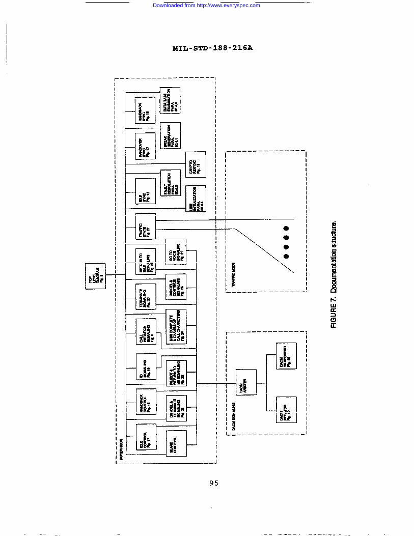
UL-STD-188-216A
r — — __—— ———— ——— — ————1
iIIIIIIIIIIIII
iI}IIIIIIIIIIIII
!IIIIIIIIIIIII
iIIIIIIIIIIII
—-—- ---— ---- ——-1I 1
IIIIIIIIIIIII
IIIIIIIIIII
;II~
III!III1III
I I I
IIIIII1IIIII
—
1 I.——————————————.
II1~
IIII1IIIIIIII
~
IIIIIIIII
II1I1IIII1
r--—— —— -- ———— —— 1II i*i
I IIIIIII i- .1.:IIIiIII III ‘4II
IIIItII
iIIIIIIIIII—.
<P
Ii!t:II ---— --— ———— — ——I
iI
95
“w. ----- --- .- —=- -————— ———&— I .
Downloaded from http://www.everyspec.com

MUL-S~-188-216A
..
LEGEND:
“EVEW
0“STAIF
. INTERFACE WITH OTHER PRMESSE=
. ENTRY POINT
mm PolNr
96
Downloaded from http://www.everyspec.com

HIL-STD-188-216A
31’7 Ml X)+lili-1
dfrlM&‘KM “
97
—.—.—=———-————————. . .—-——-—— —-———————————. —..————
Downloaded from http://www.everyspec.com

MIL-STD-188-216A
I
*
9
a
——*— -7—L2—— 2- —--z.—. 2 .. -:-- &k-
Downloaded from http://www.everyspec.com

—
MIL-STD-188-216A
II.i!!
.
●
99
.--1 . . . . . .- -k———–.
Downloaded from http://www.everyspec.com

MIL-S~-188-216A
Ua .
TnI
lad
100
-————————————————————————————— ——— — ———
Downloaded from http://www.everyspec.com
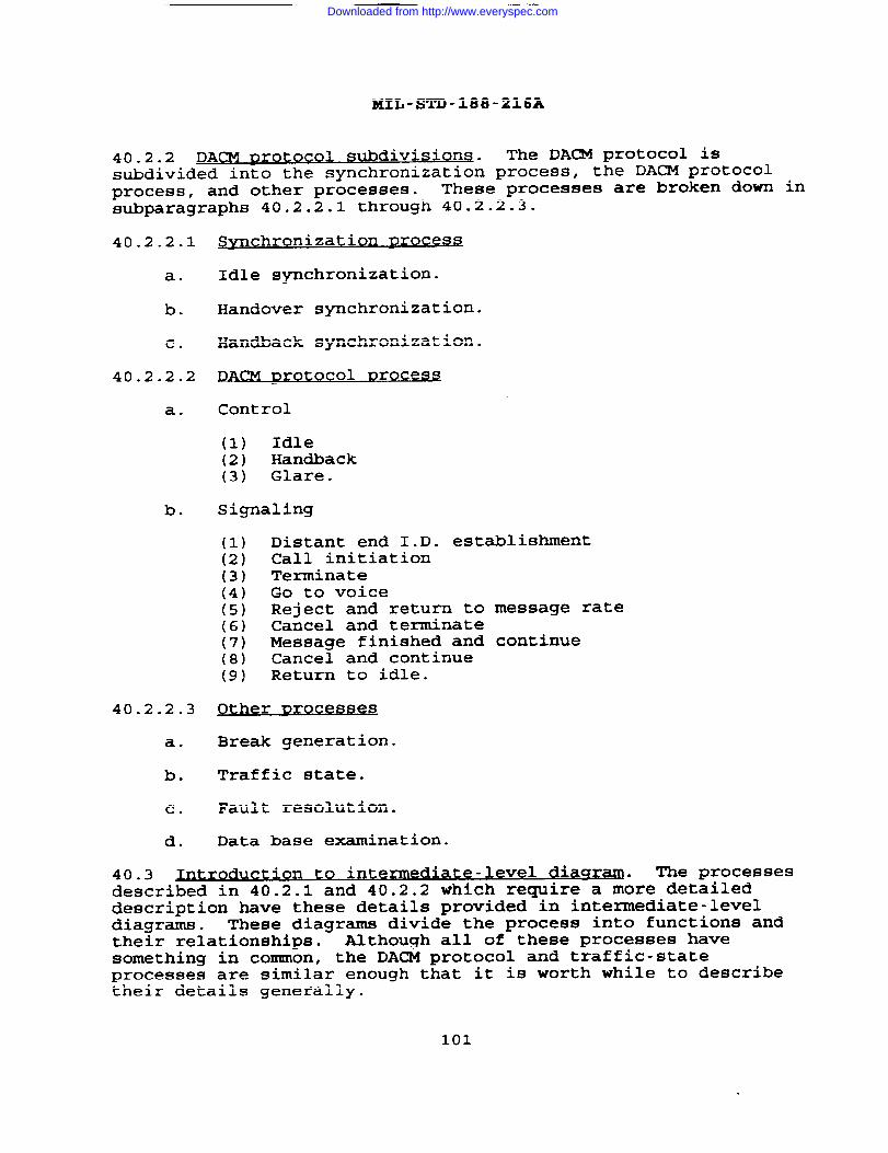
MIL-STD-188-216A
40.2.2 DACM DrotocQl sub divisions. The DACM protocol issubdivided into the synchronization process, the DACM protocolprocess, and other processes. These processes are broken down insubparagraphs 40.2.2.1 through 40.2.2.3.
40.2.2.1
a.
b.
c.
40.2.2.2
a.
b.
40.2.2.3
a.
b.
c.
d.
SVnc hronization Drocesa
Idle synchronization.
Handover synchronization.
Handback synchronization.
~ACM Drot OCO1 Drocese
Control
(1) Idle(2) Handback(3) Glare.
Signaling
(1) Distant end I.D. establishment(2) Call initiation(3) Terminate(4) Go to voice(5) Reject and return to message rate(6) Cancel and terminate(7) Message finished and continue(8) Cancel and continue(9) Return to idle.
9ther Droceese s
Break generation.
Traffic state.
Fault resolution.
Data base examination.
40.3.
to*
oductzon nte mediate-level dia~r- The processesdescribed in 40.2.1 and 40.2.2 which require a m&e detaileddescription have these details provided in intexmediate-leveldiagrams. These diagrams divide the process into functions andtheir relationships. Although all of these processes havesomething in common, the DACM protocol and traffic-stateprocesses are similar enough that it is worth while to describetheir details generally.
101
Downloaded from http://www.everyspec.com

I
Each
40.4
MIL-STD-188-216A
process is made up of:
a. Transitions to and from other processes.
b. Communication to and from the high-level functionsdescribed in 40.1.
c. Process-dependent functions (DACB signaling, timerfunctions, etc.) .
d. Basic functions
(1) External input acquisition.(2) Break detection.(3) Input line character acquisition.(4) Problem analysis.(5) Alarm analysis.(6) Character synchronization.(7) Output line character transmission.
Rela tionshiR of functions. This appendix presents thefunctions as a serial loop with exits (transactions) to otherprocesses. To simulate simultaneity, an event or lack of eventcauses transition to the next function (state) . Thisdocumentation approach neither excludes a simultaneousimplementation nor requires a serial implementation. Itonly that all functions be implemented.
50. DETAILED REQUIREMENTS
50.1 Details of basic functions
50.1.1 xE ternal inputo ,
acau>sltio n. This external input
requires
acquisition function covers the input of commands and data baseparameters . A command is an external input (see 40.1) requestinga function to be performed by DACB signaling or trafficsignaling (examples - cancel, reject, go to idle, andterminate) . The commands can cause transition to another processor actions within this process. An example of action within theprocess is message cancellation. An example of transition toanother state command is leave traffic state.
50.1.2 Break detec tio~. See 5.2.7.2
50.1.3 Jnnut line character ,,,acau~s~txo~ . This is the process of
decoding the bits received and transforming them into characters.Somein 5.(forDC4 S
of the possible errors which may be encountered are listed3.1.1, 5.3.1.4, and 5.3.1.5. This function is also assigneddocumentation purposes) the task of detecting the incomingthat force handback (see 5.2.6) .
------ -- ----------- - -- —--
102
--- -----
Downloaded from http://www.everyspec.com

MIL-STD-188-216A
50.1.4 J?rob@m ve reification. This is a process-independentfunction. It determines whether any errors of input linecharacter acquisition are “hard” or are the product of a
momentary line disturbance (see 5.3.2) .
50.1.5 am analvsi~. This is a process-dependent function.Different processes have different alarms. Alarm processingfalls into four categories.
a. Fatal - cause alarm and exit from process.
b. Non fatal - cause alarm but do not exit from process.
c. Loss of character synchronization.
d. No alarms.
50.1.6 Character synchronization. See 5.3.1.5.
50.1.7 Outnut line cha~cter tr~alon● ,
This is the processof transforming a character into encoded bits and transmittingthem.
50.2 Svnchronlzat*
ion ~roces sea. See 5.3.1.
50.2.1 Zd e sv ChXO1 n nization. This process (figure 13) is usedto establish character synchronization at the link idle rate of2400 bps (information rate) . Only multisampling is used for rateconversion and error correction. Idle synchronization may bepreceded by the following processes, for which initiator andresponder relationships are defined to resolve potential glare.
a.
b.
c.
d.
Call initiation - The master is the initiator and theslave is the responder for the idle synchronizationprocess.
Break sequence - Regardless of who initiates the breaksequence, afterwards the master is the initiator of theidle synchronization process. The slave is theresponder for the idle synchronization process.
DACB sent - The initiator is the DA/MS successfullytransmitting the DACB (i.e., DACB is ACKed) ,independent of the master/slave relationship.
Fault resolution and cryptographic synchronization -The master is the initiator and the slave is theresponder for the idle synchronization process.
103
Downloaded from http://www.everyspec.com

Z41L-STD-188-216A
BREAK DHECT’EDPASS ALARMTO ~RNAL
ESCACQUIRED D@ ACQUIRED
/
10SECOND TIMEOUT
X“ PASS AIARMTO EXTERNAL E-hufDATA BASE
EXAMINATION
INITIATORRESPONDER
SEND MARK ESC ACQUIRED D(X ACQUIRED
SEND DC4 @ 2400.-=/
10SECOND TIMEOLK
d PASS AiJ4RMTO EXIERNAl-
V v
BREAK DEIECTED
PASS A!J4RMTO EXrERNAL
* v
FJOTE:u tflooprat9Isgreat=than2400*
FIGURE13.klk~.n.
104
Downloaded from http://www.everyspec.com
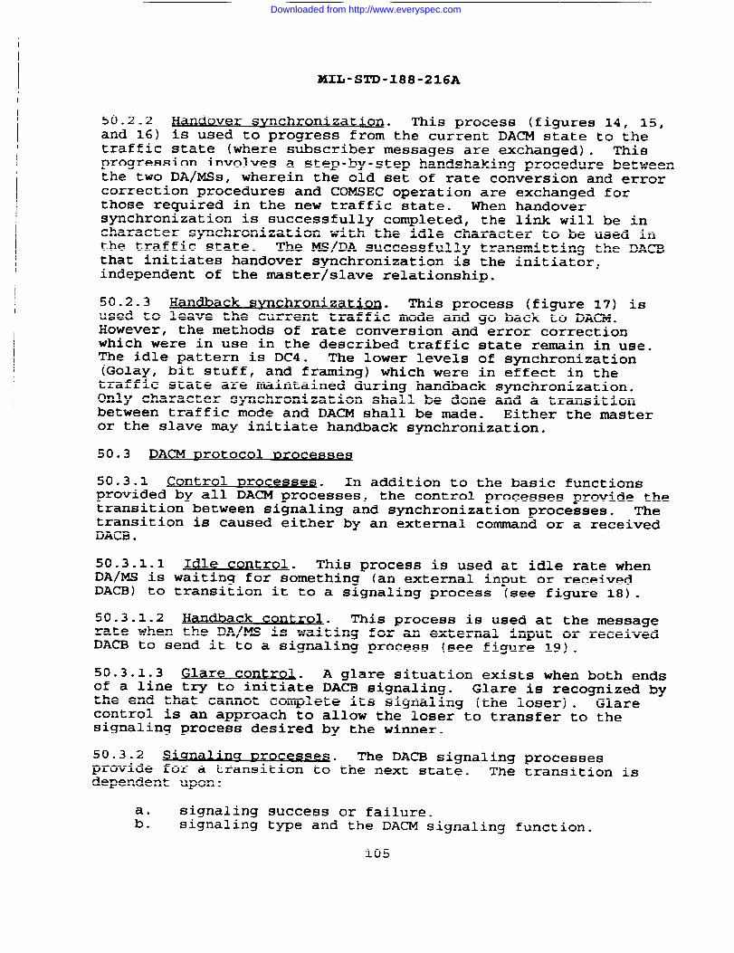
lKXb-STD-188-216A
50.2.2 Handover SYnchro nization. This process (figures 14, 15,and 16) is used to progress from the current DACM state to thetraffic state (where subscriber messages are exchanged) . Thisprogression involves a step-by-step handshaking procedure betweenthe two DA/MSs, wherein the old set of rate conversion and errorcorrection procedures and COMSEC operation are exchanged forthose required in the new traffic state. When handoversynchronization is successfully completed, the link will be incharacter synchronization with the idle character to be used inthe traffic state. The MS/DA successfully transmitting the DACBthat initiates handover synchronization is the initiator,independent of the master/slave relationship.
50.2.3 Handback sYnc hronization. This process (figure 17) isused to leave the current traffic mode and go back to DACM.However, the methods of rate conversion and error correctionwhich were in use in the described traffic state remain in use.The idle pattern is DC4. The lower levels of synchronization(Golay, bit stuff, and framing) which were in effect in thetraffic state are maintained during handback synchronization.Only character synchronization shall be done and a transitionbetween traffic mode and DACM shall be made. Either the masteror the slave may initiate handback synchronization.
50.3 DACM ~rotoc 01 ~roces~e~
50.3.1 control nroce sseS. In addition to the basic functionsprovided by all DACM processes, the control processes provide thetransition between signaling and synchronization processes. Thetransition is caused either by an external command or a receivedDACB .
50.3.1.1 Idle cc)ntrol . This process is used at idle rate whenDA/MS is waiting for something (an external input or receivedDACB) to transition it to a signaling process (see figure 18) .
50.3.1.2 Ha dbacn k control. This process is used at the messagerate when the DA/MS is waiting for an external input or receivedDACB to send it to a signaling process (see figure 19) .
50.3.1.3 Glare cent rnl . A glare situation exists when both endsof a line try to initiate DACB signaling. Glare is recognized bythe end that cannot complete its signaling (the loser) . Glarecontrol is an approach to allow the loser to transfer to thesignaling process desired by the wimer.
50.3.2 ~ Drocesses The DACB signaling processesprovide for a transition to-the next state. The transition isdependent upon:
signaling success or failure.:: signaling type and the DACM signaling function.
105
Downloaded from http://www.everyspec.com

MIL-S~-188-216A
I
106
Downloaded from http://www.everyspec.com
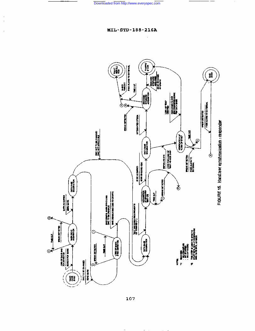
t
MIL-STD-188-216A
+
‘T’
!h F
- . . ..0
107
. . .
Downloaded from http://www.everyspec.com
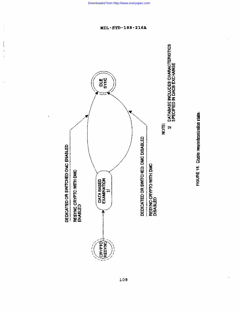
/
MIII-STD-188-216A
\
D—u
108
n-. I I
Downloaded from http://www.everyspec.com

MIL-STD-188-216A
==-If--@SENDDCXENCODEWAT MSG RATE DC4 ACQUIRED
ALARM TO EXERNAL
● THEM ISSENT MULnSAMPLED, ORBITSTUFFED,OR GOLAY ENCODED, ETC.JUSTAS WAS THE 8ESC”USED INTHE PRECEDING HANDOVERSYNCHRONIZATION.
INMATORRESPONDER
BREAK DETECTED
PASS ALARMTO EXTERNAL \~w
D04 ACQUIREDSEND D(X ENCODED’
ALARM TO EXrERNAL
FIGURE 17.HWldlmM ~.
109
Downloaded from http://www.everyspec.com
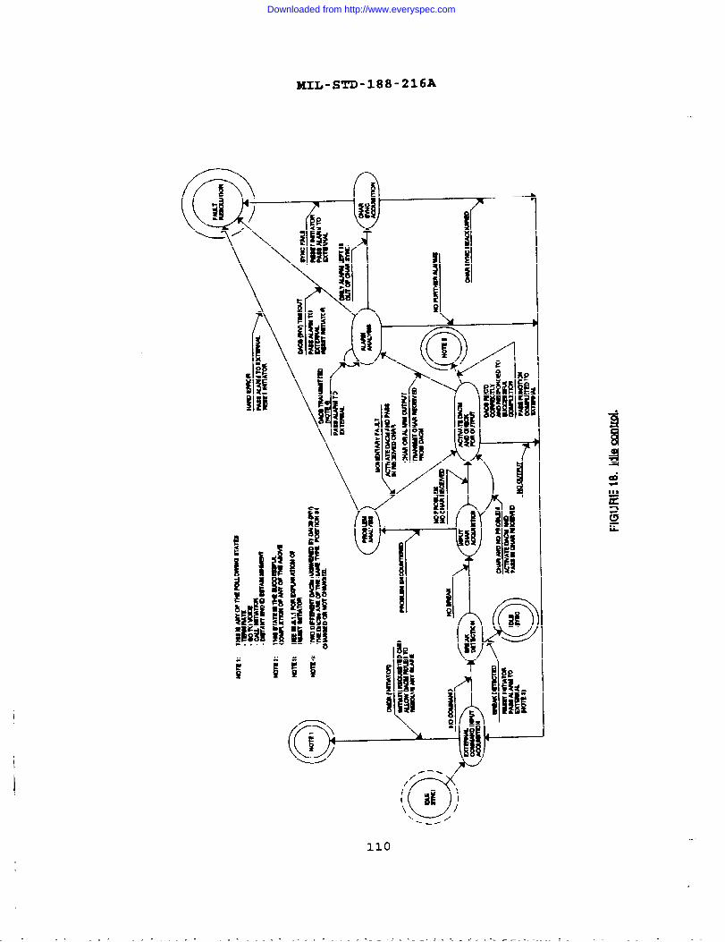
MIL-S~-188-216A
m
110
I I
—
Downloaded from http://www.everyspec.com

MIL-STD-188-216A
1
111
.
Downloaded from http://www.everyspec.com
50.3.2.1
50.3.2.2
50.3.2.3
50.3.2.4
50.3.2.5
50.3.2.6
50.3.2.7
MIL-STD-188-216A
Dist ant end I.D. est abolishment. See figure 10.
Call initiation. See figure 11.
Terminate. See figure 20.
to voice. See figure 21.
~ct ad return t.o messaqe rate . See figure 22.
Cancel and termmateB
. See figure 23.
~sa~e comnlete and chancre ch~~~ t#
ic~. See
figure 24.
50.3.2.8 Cance 1 and continue with new characteristi~. See
figure- 25.
50.3.2.9 Return to,dle . See figure 26.
50.4 Others
50.4.1 q~erat~.
. This process is used to force idlesynchronization when normal processing has failed to obtainsuccessful synchronization. Break generation is passed as analarm to external. Break generation can be accomplished asdescribed in 5.2.7.
50.4.2 Traffic,
s= . The purpose of figure 27 is to show thegeneral functions affecting the overall processing of messagedata. This figure shows the internal processing of the trafficmode activation state shown on the intermediate-level diagram.The type of alarms generated by the lower-level processingfunctions will cause the alarm analysis state to determine if thetraffic mode state can continue normal message processing or iftermination may be required by the fault resolution state.
50.4.3 Fau lt resolution.
. The purpose of this process is todetermine if the connection will continue or be released. The
basis for the decision is as described in 5.3.3.1, 5.3.3.2, and5.3.3.3 for time-outs.
50.4.4 Pata base examl~* The purpose of this process is to
detemine the action to be ta~en depending on both the fixed linecharacteristics and the information specified in the last DACBtransaction.
50.4.5 Line initialization- The purpose of this process is toallow for delays in establishment of the data connection and toprovide for initial COMSEC synchronization.
112
Downloaded from http://www.everyspec.com
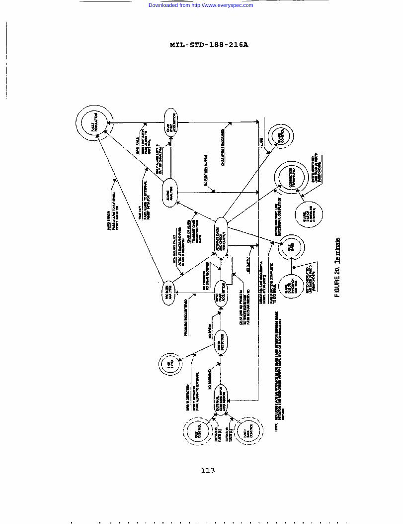
MIL-STD-188-216A
I
113
Downloaded from http://www.everyspec.com

lKIL-STD-188-216A
--
114
/
S
al
Downloaded from http://www.everyspec.com
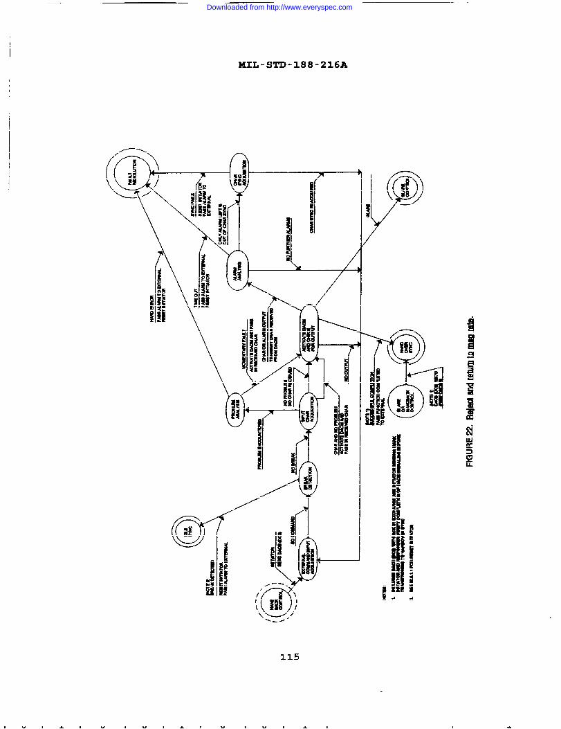
MIL-STD-188-216A
\y,/.4
115
Downloaded from http://www.everyspec.com

MIL-ST’D-188-216A
—
d
‘--”
116
Downloaded from http://www.everyspec.com
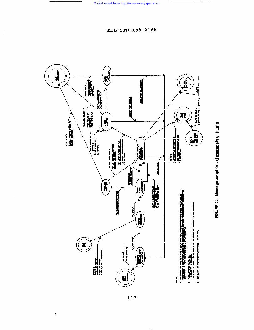
I HIL-SI?D-X88-216A
----
117
/
/
Ii
!
Downloaded from http://www.everyspec.com

XIL-STD-188-216A
118
Downloaded from http://www.everyspec.com
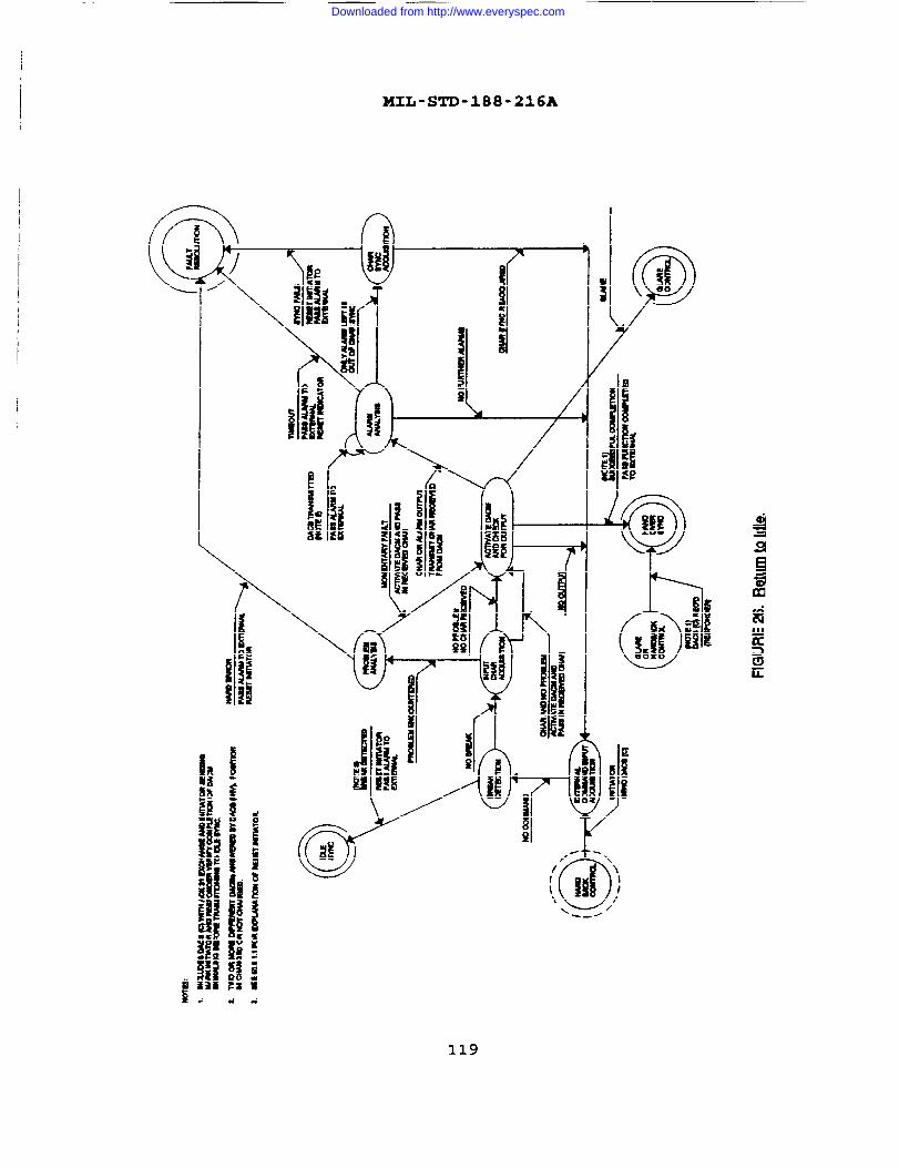
MIL-STD-188-216A
119
Downloaded from http://www.everyspec.com
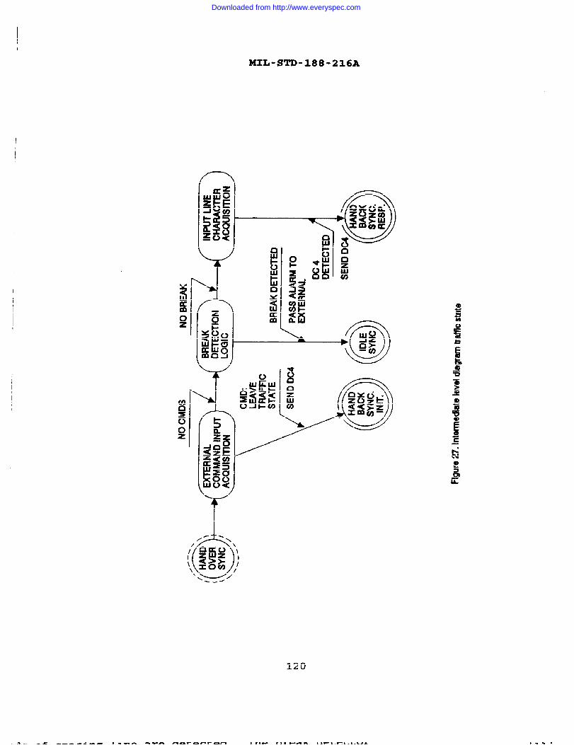
II
MIL-STD-188-216A
I1
ii!
*
1’
\
Ii
120
Downloaded from http://www.everyspec.com

MXL-STD-188-216A
50.5 Lower-level diaqrams
50.5.1 Data ada~ter control mode. DACM is a signaling method
which translates process requests to output DACBS and input DACBSto process requests. The process requests are those listed underDACM protocol processes (signaling) (see 50.3). Only one may be
active at a time because of the nature of these process requests.The majority of the requests require transition to another state.
If more than one were processed simultaneously, the next statecould be indeterminate. It is the responsibility of the processrequestor (an external function) to have only one requestoutstanding. It is the responsibility of DACM to resolve aprocess request and an incoming DACE3 (which signals a requestfrom the distant end) . The rules for translating a processrequest are called DACM responder (see figure 28) . The function
of deciding which set of rules applies is called the DACMarbiter.
50.5.1.1 ~A~ arb iter. The rule for the DACM arbiter is simple.If the initiator function is not active, the responder functionis active. The initiator function is made act~ve whenever acommand (CMD) is received from the ~/DTEO The initiatorfunction is made inactive (reset) whenever:
a. DACM signaling is successfully completed.
b. DACM signaling backs down because of glare.
c. DACM signaling is not completed due to exit for reasonsexternal to DACM rules, such as break detection or exitfor failures covered by DACM rules.
50.5.1.2 DACM initiato r. When a CMD is received, transmissionof the proper DACB is initiated. The DACB is transmittedcontinuously until:
a. An answer is received. An answer is defined as:
(1) ACK 31(2) WBT 31:(3) Response DACB. See responder for description of
DACB validation.
b. A time-out occurs.
c. A glare is detected.
d. Transmission is terminated.
50.5.1.3 DA(2M r~ontk . When a valid DACB is received, it isacknowledged and the process it requested is communicated to ahigher level.
121
w I
Downloaded from http://www.everyspec.com

ZKIL-STD-188-216A
i
I
l!?ifgF
\!!!il
1
122
Downloaded from http://www.everyspec.com

I lKIL-STD-188-216A
APPENDIX D
GOLAY CODING FOR DACM AND MESSAGE TRAFFIC
Appendix D contains specific information in support of MIL-S~-188-216. Appendix D is not a ma.ndatoq part of this document.Implementation of the Golay Code is optional, but whenimplemented, it shall be accomplished in accordance with thisAppendix (APPENDIX D) .
123
Downloaded from http://www.everyspec.com
MIL-STD-188-216A
10. GENEIUkL
10*1 BKRQ=* The purpose of this appendix is to explain howGolay coding is used for DACM and message traffic.
10.2 iizQRf2* This appendix contains infomnation pertaining to
Golay coding that will assist the user in better understanding
its relationship with the main body
20. APPLICABIJE
of this document.
DOCUMENTS
Not applicable.
30. DEFINITIONS
For purpose of this appendix, the definitions of section 3 of
this document and FED-STD-1037 shall apply.
40. GENEW REQUIREMENTS
40.1 ~ ion FE ca ilit . FEC is capable
of being utilized for data rate transfoznnations listed in table
XXX* For start-stop data, Golay Coding shall only be utilized
with data which are bit synchronized to the DA clock and haveintegral bit length start-stop bits.
40.1.I The 1/2 rate Golav code. The 1/2 rate Golay code is
based on use of the [23, 12] Golay code, extended to 24,bitstotal length by addition of a zero bit. Eleven check bits are
derived for each sequence of twelve information bits. The elevencheck bits follow the twelve information bits, and the twenty-fourth bit is set to zero. Transmission of the resulting 24 bitcode word shall constitute 1/2 rate Golay code transmission (seefigures 29 and 30 for specific examples) . Bit 1 of the 24 bit
FEC code word is bit 1 (b,) or bit 5 (b~) of a DACM character.DACM characters are the ESC, DC4, DACB characters, and DACBacknowledgements. Bit 1 of the 24 bit FEC code word is bit 1
(bl) ‘r biftr~i::: ‘f the ‘odeI or Mode VI characters (data,
control, SPC, ACKS, CAN, =, etc-)-
124
Downloaded from http://www.everyspec.com
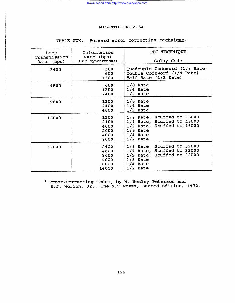
I
MIL-STD-188-216A
TABLE XXX. Fomard error correcting tech.nicfu~=
Loop Information FEC TECHNIQUE
Transmission Rate (bps)Rate (bps) (Bit Svchronousl Golay Code
2400 300 Quadruple Codeword (1/8 Rate)600 Double Codeword (1/4 Rate)
1200 Half Rate (1/2 Rate)
4800 600 1/8 Rate1200 1/4 Rate2400 1/2 Rate
9600 1200 1/8 Rate2400 1/4 Rate4800 1/2 Rate
16000 1200 1/8 Rate, Stuffed to 160002400 1/4 Rate, Stuffed to 160004800 1/2 Rate, Stuffed to 160002000 1/8 Rate4000 1/4 Rate8000 1/2 Rate
32000 2400 1/8 Rate, Stuffed to 320004800 1/4 Rate, Stuffed to 320009600 1/2 Rate, Stuffed to 320004000 1/8 Rate8000 1/4 Rate
16000 1/2 Rate
] Error-Correcting Codes, by W. Wesley Peterson andE.J. Weldon, Jr., The MIT Press, Second Edition# 1972=
125
Downloaded from http://www.everyspec.com
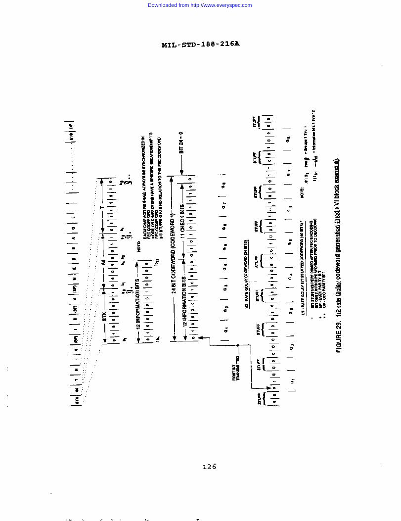
XIL-S~-188-216A
:{ –o
0h
T- .....—
- .
0 0
1?
!!{–o0.
0
+
T_o :(J9. —o
t=
o
I!{–o0d:. —o
.0 e-
:1-w
e z{–o0s:&l 0<
a I.._. .! ! o..—, .. .. .. , k. .aB
Eo
0w . .. .
+=
o.
. 0.
.0
. . .
. . .
. .._
. . .
. . . 0
I_.,. _,... . . 0,... . .
12–0. . .
. . ..,. 0. . . 0
k =E{—o
0
—!..,..
ho
-... . . .
.#.T’” +x....0.
—; ; .“ .—
LT 1 0- . . .. . . . I IT..,.. . . . .
. . .-..—“::.
I x::.
—, . .s::
126
Downloaded from http://www.everyspec.com
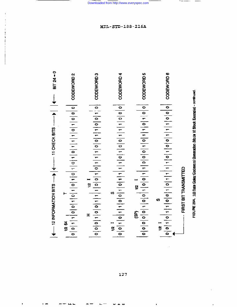
ZKIL-STD-188-216AI
1
m
10 0 00 0
00 0
0
0
o 00 w-
00
0
0
0
0 0 0
0
0
0T-
00
0
0 00
u)o 0
o0
0 T-
ox —
o
o
1 0
00
127
I I m -—UK- = — h— warm I
Downloaded from http://www.everyspec.com
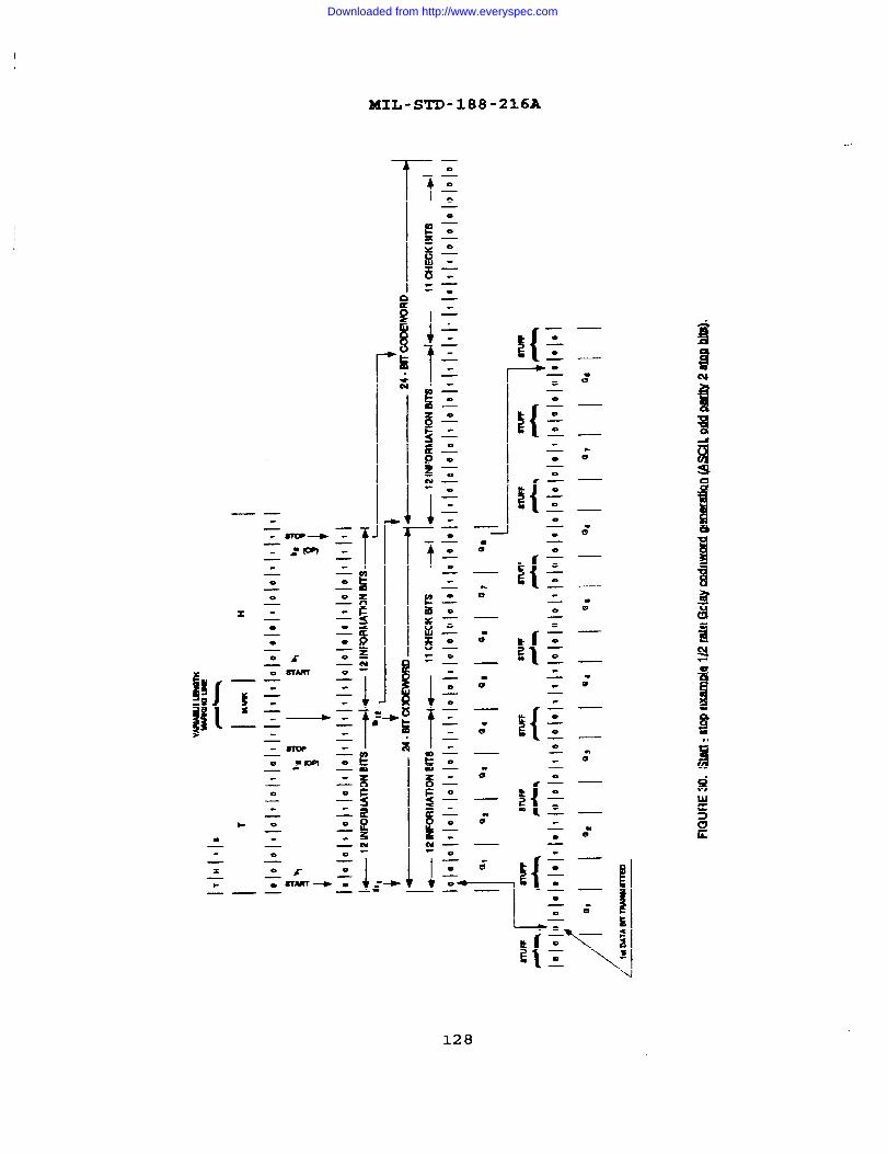
MIL-STD-188-216A
—
t
0.
0
0—
o
0—
o—
.
——
0—0—
e—
0—
.
o—
${o—
o—
o
0—
0
—
v—
0—
${0—
0—— —
————
o—
o—
0—
0 e-o
to
—0
0—
${0
—
0
—
—o
— E0 —
0 8-0
o—
m—
0
0—
~{o
—
o—.—. 9-0-0
—
0 .—
${0—
e—
8TOP “—
o—
.- m o—
00
0.—o
—o
—
—
i{o
—
o—
o—
—
b o
—o
—0
—
—
0—
0
—0
—0
—
0
0
1 H—4-* —K o
—x
.— —o
—0
—
128
Downloaded from http://www.everyspec.com

.
MIL-STD-188-216A
40.1.1.1 Check bits derivation. The transmitting DA/MS shallgenerate the check bits using the following generator polynomial:
as specified
g(x) =xll+x 10+X6+X5+X4+X2+1
herein. Note, that, using modulo 2 addition,
x%.(l?.i”+f+?.l?+f ●lx#+#+x7+#+x64x+l)(x+l)
S(X
The eleven check bits shall be as derived from the followinggenerator matrix G:
where the matrix contains the coefficients of the polynomials onthe left. By interchanging the I and P columns to obtain matrixT; i.e.
G=[P,II (12JQ3) => [I,Pl(12fi~)=T
the transmission order and value of the code word bits can beobtained by matrix multiplication (xnodulo 2 addition withoutcarry) as follows:
[ % ‘NFo- %2 ] Jl,lq = [ lNFO~CHECK_ ]
t
(wdq ~ J(laai)
t
(1)(23)
40 .1.2 ~ouble code word transmission Double code wordtransmission (1/4 rate Golay) is the ~ransmission of a 1/2 rateGolay code word twice contiguously (see figure 31) .
40.1.3 Qua dru~le,
code word Inlssion. Quadruple code wordtransmission (1/8 rate Golay) is the transmission of a 1/2 rateGolay code word four times contiguously (see figure 31) .
129
— .—. ______ .
Downloaded from http://www.everyspec.com

7
C9
IA
w
m
<
MIL-STD-188-216A
w
LLJ
n
<
a
a
130
.—_____
Downloaded from http://www.everyspec.com
MIL-STD-188-216A
Custodians:
Army - Sc
Navy - EC
Air Force - 90
DISA - DC
Review Activities:
Amy - AC
Navy - NC, TD, OM
Air Force - 02, 17
DISA
OASD - IR
User Activities:
Army - CR
Navy - MC
Air Force - 13
DISA
CONCLUDING MATERIAL
Preparing Activity:
DLA - DH
DISA - DC
(Project TCTS-261O)
131/132
Downloaded from http://www.everyspec.com
MIL-STD-188-216A
(This page intentionally left blank.)
Downloaded from http://www.everyspec.com

I
I STANDARDIZATION DOCUMENT IMPROVEMENT PROPOSAL
INSTRUCTIONS1. Thepreparing activity must complete blocks 1, 2.3. and 8. In block 1, both the document number and rev!sio~
letter should be given.
2. The wbmitte~of this form must complete blocks 4, S, 6. and 7.
3. Thepreparing activity must provide a reply within 30days from receipt of the form.
NOTE: This form may not be used to request copws of documents, nor to request waivers, or clarification ofrequirements on current contfacts. Comments sdrxnittd on this form do not constkuteor im~y wthorization towaive my potion of the referenced document(s) or to amend contractual requirements.
. . . .,,,#;qgcQMMEMb&mGq:jJi LyT;!y8&!~;
..’ ‘..:”’: ““”” L DOCUMENT OATE (YYHD)
93 FE8 20,..., ...:.”*vy?.”..“ ...>:;~%,:<:???*%:k DOCUMENT TITLElnteroperabi1ity Standard for Data Adapter Control ModeL NATURE OF CHAWE (timfy paragraph numtmr ●nd mckde ~ ~, If pO$f@@. A~~ •~a -U U ~
●
. REASON FOR RECOMMENDATION I
$%’E&,. .. . . .
——— . ... . . . . ... . . . ~-~&$:<,.* ”2:”.qmi*’*m””’’”w*;;.’’::”:’ ,,,..-.“ ~..: . ...’.*, ‘“.
,~,;s$;$-~~%x.~.iwF*F:>:;&-&+&-E’;! ::......:,~
.7 ..”----- . . . . . . . ~h, . . . J . .
~:
. . . . .~J&~9:c’: I“ ‘J%%#m.:>.... . ..........-....,’,. > . . . . . ... . ,< ..v.v.... ...4”. . . . .. . . . . . .. . .. . . . . . ..”:.WA. J.. . . .. . . .. . . . . . . A,. . . . . . . . . . . . . . . ..W-; ., .x>%.
... ,............::\<v . . .“:,:..:,:,s;xy.?v,<+p?”~s>> -wy$-’
. . . “‘“~>?e~ . ... .... .. ....;..iH.m**7~:. fl,................. . .m . ... . . . ...... ... . . Jm . . ...’ ,.V...>. . ..*... AA
=’:’1:#w-?!-*+iY$#. ?~:”- Sabw&’i’;’; ...::<:<!.!. .. ...... .. .......w@~.$.w2it..sq.&3%*y$z;:::s:~~&<$*,, ; ““V=.L\.f, ,.,. >.,<...:., .+<: ._,., .+, . . . . . +.,; . .. ...<+<.*. $.<+:. x... <. ‘ . . . ... .-‘ -- -.-=. .--=-w...........,: .,.. ..
t.’.:..: - .>~.j :.:..;.:n*>&w.*&x:;:*;$.:.:?” “ ‘ $$::s..,,, .*$+,v:m:[email protected].;..>?,?6.,zF~*.;3.......... ,+,. .. ..,...*.... ..+.&,&&,.;* .:.+.+.,. F—S&R --%%”“‘;iv””&:md**W*-- ..’ “!@i:..<
,<f+%%.$ :.....iy: .:..........\ ............+:%’.;. .. . ., ..,.,.:... ..... . .......,. .. ... .. .. ... .....>...... .. * ‘y:: ?w&M*x2i&3& ‘.; , .,...,. .,.. ”.:...:. .:: . . ...+ . . . . ..,..~.:k:.+ ;:y.:~,.:{.,. w+vJ3 . .. . . .. . .. . . .. .. . . . .. .y ... . >+. .: .. . . .~. .. . . . . . . . . . . . . .
.>.. .=.: ,. WY-% . . . . . . . . . . . . .
2.>.$..,..+.:. ..... f <:~k:>.y.q y+j+ .. ...-.> ..? .,: .,.,,.; ,,,
. . . . .
.X,>.::.* ~ .:?,., .... .,....+f.<.......+..>.~,..?:~.....,...........>..-.,...$...,.. ...~j:,, : .. . . ... .%...,
., . . . . .. . . . . . . . . . . :.”.....:.: ““”:”:~j~’” .:.’:.”...>:5W..W..:SF...-’?+xy?y{ r.”:. :.::.,::.:..2..<:: h :; :.&v.. . . . ~ ... . .?...pyyy:y:.: . .. ..:;: . . . n::.... :> ...< , :. .: . . . .“.,..,>,,,:,..,:.. .’.y, - ,..:: ... ..%....... .. . . . . . . :.,: by.’.,...
“z?;~;&~F$&:&””,,,,.,.......<*.*.f.$$..*.2sz:z+$$%$$*>*;*~$e2.wdti:;<ti;i?c;y:*:.. ..... . ........... ....... . :.%: ..:~-:~;@;+:;yy f.::<: :-M:<.<$.>A: :,. ~.. >:.,. .. v.. .. . .. . .. .::; ; : ;.+
. .:...,:,; , ,.; .,.. Y,, . . . . . . . , ..y, ,,f. j :::. .,O . . . . . ad% .m*E ?:;;:;;;.;;:::@,%.;.<f..“:i+ “.::. ; .:,.....+.y.y$fi-y~m.w-k::,.. .:.:..w.. ... . .
L ?RWAR119G ACTIVITY
I. NAME b. TEL&PWfUE (Ind- Am# Cm)N rector, Joint Interoperabi 1ity and (1) Commoraal (2) AUTOVON
hgineering Organization (JIEO) (908) 532-7726 AV 992-7726AOORESS (hdude Zip Code) IF YOU 00 NOT RECMW A REPLY WITHIN 45 DAYS, CONTA~:
ITTN : TBBD Dsfms@ Quality and Standardization Offko
‘ort Mmmouth, IL) 07703-5613 5203 Lewouq Ptk@, Sulto Iu03. Falls Chwch, VA 22041-3466Tekwmone (7031 756-234) AuTOVON 289-2340
00 Form 1426, 0(5 89 +~vlo~$ ●dttlons arp ObSOtete‘s :90
Downloaded from http://www.everyspec.com