Embed Size (px)
Citation preview

ORIGINAL RESEARCH Open Access
Microgrid dynamic security consideringhigh penetration of renewable energyG. Magdy1,2*, Emad A. Mohamed1, G. Shabib2,3, Adel A. Elbaset4 and Yasunori Mitani1
Abstract
This paper presents a coordination strategy of Load Frequency Control (LFC) and digital frequency protection foran islanded microgrid (MG) considering high penetration of Renewable Energy Sources (RESs). In such MGs, thereduction in system inertia due to integration of large amount of RESs causes undesirable influence on MGfrequency stability, leading to weakening of the MG. Furthermore, sudden load events, and short circuits causedlarge frequency fluctuations, which threaten the system security and could lead to complete blackouts as well asdamages to the system equipment. Therefore, maintaining the dynamic security in MGs is one of the importantchallenges, which considered in this paper using a specific design and various data conversion stages of a digitalover/under frequency relay (OUFR). The proposed relay will cover both under and over frequency conditions incoordination with LFC operation to protect the MG against high frequency variations. To prove the response of theproposed coordination strategy, a small MG was investigated for the simulation. The proposed coordinationmethod has been tested considering load change, high integration of RESs. Moreover, the sensitivity analysis of thepresented technique was examined by varying the penetration level of RESs and reducing the system inertia. Theresults reveal the effectiveness of the proposed coordination to maintain the power system frequency stability andsecurity. In addition, the superiority of the OUFR has been approved in terms of accuracy and speed responseduring high disturbances.
Keywords: Digital frequency relay, Load frequency control (LFC), Microgrid, Renewable energy sources (RESs), Dynamic
1 IntroductionIn past, several cascaded blackouts happened in elec-trical power systems due to frequency instability in caseof the imbalance between the electrical load and powersupply or N-1 contingency [1]. Nowadays, this problemincreased after the growing of renewable energy sources(RESs), which have several impacts on the dynamic se-curity of the islanded microgrids (MG). The dynamic se-curity of MG is the ability of electric grid to maintainthe system synchronism when subjected to various tran-sient disturbances [2]. Figure 1 shows the dynamic se-curity issues of MG. One of these issues is the lack ofsystem inertia due to the high integration of RESs. Con-sequently, increase the voltage and frequency fluctua-tions, loss of generation source, forced load shedding,
and short circuit faults [3]. Furthermore, RESs exchangeelectrical power to MGs through power electronic in-verters, which cause higher power fluctuations than thetraditional synchronous generators. Hence, if the RESspenetration becomes larger, the islanded MGs might be-come insecure as the stabilizing in system frequency andvoltage is difficult in that situation [4, 5]. Moreover,there will be unbalanced between the generation andload due to the variable nature of RESs. These changeslead to the appearance of challenges for the MG dy-namic security such as, nature transient variations inMG. These variations are highly affected by the oper-ation mode of MG whether grid-connected orstand-alone [6, 7]. Moreover, the selection and coordin-ation of conventional protective relays became morecomplex due to the frequent bidirectional power flow inconnection feeders of MGs to utility grids [8, 9]. Regard-ing to the previous challenges, the stability and protec-tion coordination issues have become interested andmust be highlighted. Therefore, this work proposes a
* Correspondence: [email protected] of Electrical Engineering, Kyushu Institute of Technology,Tobata-Ku, Kitakyushu-shi, Fukuoka 804-8550, Japan2Department of Electrical Engineering, Faculty of Energy Engineering, AswanUniversity, Aswan 81528, EgyptFull list of author information is available at the end of the article
Protection and Control ofModern Power Systems
© The Author(s). 2018 Open Access This article is distributed under the terms of the Creative Commons Attribution 4.0International License (http://creativecommons.org/licenses/by/4.0/), which permits unrestricted use, distribution, andreproduction in any medium, provided you give appropriate credit to the original author(s) and the source, provide a link tothe Creative Commons license, and indicate if changes were made.
Magdy et al. Protection and Control of Modern Power Systems (2018) 3:23 https://doi.org/10.1186/s41601-018-0093-1

coordination of LFC and digital OUFR for maintainingthe dynamic security of an islanded MG.The frequency control and protection of the electrical
systems are the two main sides to investigate the dy-namic security of the MG system. There are severalstudies have dealt this problem from the control sidesuch as conventional controllers with different algo-rithms and optimization techniques [10, 11], intelligentcontrol, (i.e. Fuzzy Logic Control (FLC)) [12, 13], and ro-bust control [14, 15]. X. Tang et al. [16] proposed anovel technique of frequency control, which is V/f droopcontrol (VFDC) and P/Q droop control (PQDC) com-bined for islanded MG based on different energy storagedevices. While, Sedghi and Fakharian [17] used the co-ordination of robust control and fuzzy technique to ad-dress the frequency control issue in [16]. ModelPredictive Control (MPC) based LFC for MG based onthe coordination of wind turbine and Plug-in HybridElectric Vehicles (PHEVs) is proposed in [18] by Jonglaket al. Furthermore, Wang et al. [19] studied and analyzedthe voltage security issue for MG using ConvolutionalNeural Network (CNN).On the other side, the protection systems have chan-
ged significantly from the bygone decade and willchange continuously as a result of the advancement oftechnology. Therefore, power systems designers areseeking to apply digital devices to handle the increasingcomplexity of power system, which improve the costand usability. Subsequently, the digital technology hasappeared in the protection system of microprocessor re-lays since 1980 and developing to those with communi-cations interfaces in the a990s [20]. Today, digital relayshave featured with high speed communication, whichhelped in replacing wires for safety interlocking, control
and also circuit breakers tripping action. Furthermore,there are many applications of digital relays in transmis-sion and generation system protection due to their flexi-bility, high performance level, and capability of operatingunder different temperatures compared to the classicalelectromechanical relays. Therefore, this study focuseson the digital protection device, (e.g. OUFR) to be coor-dinated with LFC for MG dynamic security. There areseveral studies have dealt this problem from the shortcircuit fault side only such as, the optimized time-basedcoordination of conventional over-current relays; whichis the earliest protection technique for utility grids in-cluding micro-grids [21]. This method has a limit in itsability of multi-relay protection because of its high sensi-tivity to components parameters in high fault levels.Sheng et al. [22] presented a multi-agent method dependon assumptions of high fault current levels. However,this method has been developed to island the MG forany fault in the utility grid and also disconnecting mostof distributed generations (DGs) for faults within theMG. Furthermore, some studies handled the frequencyprotection problems such as; Laghariet et al. [23] appliedan intelligent computational technique for load sheddingof the power system under faulted conditions. Moreover,Komsan and Naowarat [24] discussed the same issue byusing the rate of change under frequency relay to im-prove the load shedding scheme in MGs. Further, Freitaset al. [25] presented a comparative study of the rate ofchange of frequency (ROCOF) and vector surge relaysfor distributed generation applications. However, theyfaced a very hard task in relays coordination as their de-sign may not detect the islanded conditions within therequired time. Teimourzadeh et al. [26] introduced anew Region of Attraction (ROA) based protection zonefor the detection of MG security status. However, theproposed approach is an efficient index for providing aquick detection of MG security status. Jose Vieira et al.in [27] proposed the coordination of ROCOF andunder/over frequency relays. However, this presentedcoordination has a drawback, which it did not com-pensate the frequency fluctuations within the allow-able frequency limit due to the action of the relay isenergized when the system frequency become out ofthe allowable limit. Such a problem can be overcomeby designing the proposed coordination strategy ofLFC and digital OUFR for an islanded MG systemdynamic security.According to authors’ knowledge, some gaps still need
to be filled in the MG dynamic security issue. Therefore,this paper proposes a design of digital over/under fre-quency relay coordinated with the LFC for the dynamicsecurity of an islanded MG system, which consist ofthermal power plant, PV, wind power generation(WPG), and domestic loads. To prove the effectiveness
Fig. 1 The microgrid dynamic security issues
Magdy et al. Protection and Control of Modern Power Systems (2018) 3:23 Page 2 of 11

of the proposed coordination in protecting the MGagainst frequency variations, it has been tested underdifferent scenarios of disturbances such as, high penetra-tion level of RESs, reducing system inertia, and suddenload variations. The remaining of this paper is arrangedas follows, Section 2 discusses the problem description.The structure of the studied MG system with the stateequations are presented in Section 3. The coordinationof control and protection methodology is described inSection 4. Section 5. shows the simulation results of theproposed coordination which applied to the MG. Finally,the last section concludes the results and advantages ofthe proposed method.
2 Problem formulationThe dynamic security issue is one of the most critical is-sues, which face the power system designers. Dynamicsecurity refers to the ability of the electrical power sys-tem to maintain the synchronism when subjected to asever trainset disturbance [2]. Therefore, the dynamic se-curity deals with disturbances that impose momentouschanges into the system variables. Among these areshort-circuit faults, loss of a dominant generationsource, and loss of a large load. The system response tothese disturbances includes large deviations in the sys-tem variables such as voltage magnitudes and angles,generator speed, and system frequency [12]. Hence, thebalance between the input mechanical power and theoutput electrical power is disturbed. And then, the mis-match makes the synchronous generators (SGs) eitheraccelerate or decelerate.On the other hand, preserving dynamic security is
different between the bulk power systems and MGs. Inthe case of the bulk power systems, the conventionalsynchronous generators are considered the source ofthe dynamics. Likewise, in MGs, the RESs are the hostof dynamics. Moreover, most of the available methodsfor preserving the dynamic security of the bulk powersystems are considered inefficient for MGs due tothese methods are devised based on the features of thebulk power system, which are significant inertia con-stant and rather slow dynamics. Therefore, this re-search studies the dynamic security issue in themicrogrids. In the MGs, the RESs exchange power tothe MGs through inverters/converters. The powerelectronic interface-based RESs are static devices with-out any rotating mass so that the associated inertiaconstant is roughly zero. On the other hand, syn-chronous generators-based RESs are small-scale gen-erators with noticeably low inertia constants [28].Such a low inertia constant renders the MGs morevulnerable to the transients than the bulk power sys-tems. Furthermore, the power generation from RESsare unpredictable and variable, results in more
fluctuations in power flow and frequency in the MG,which significantly affects the power system operation.Also, the randomly changes in load power demandcaused a bad response to the PCC voltage, active, andreactive powers transfer. To solve the dynamic stabil-ity problems, it must be determined the effective fac-tors, which steer the MGs toward the insecurity.These factors include a low inertia constant, frequentfault occurrence, and inadequacy of existing protec-tion schemes. Moreover, the performance of the pro-tection system is one the most significant factorswhich imperils the dynamic security of the μGs.Therefore, the stability and protection coordination is-sues have become a center of interest especially forpower system researchers. Hence, this research pro-poses an efficient coordination of secondary fre-quency control (i.e., LFC) and the digital OUFR foran islanded MG security considering high penetrationof RESs.
3 System overview and modeling3.1 Microgrid systemThe MG is a small power system, which consisted ofDistributed Generators (DGs), domestic loads, energystorage systems (EES), and power conditioning units.The MG is distributed through low voltage distributionsystems and the electric power is mainly generated byDGs such as photovoltaic (PV), wind turbines (WT),hydropower plant, fuel cells, etc. This research focuseson the islanded MG, which includes 20 MW of Thermalpower plants, 6 MW of a wind farm, 4.5 MW of a solarfarm, and 15 MW of domestic loads. The simplifiedmodel of an islanded MG with influence of the proposedcoordination, the coordination of LFC and digitalprotection is shown in Fig. 2.In this study, some physical constraints effects are
taken into consideration for modelling the actualislanded MG such as; the speed governor dead band(i.e., backlash) and Generation Rate Constraints (GRC)of power plant. Whereas, backlash is defined as the totalmagnitude of sustained speed change. All speed govern-ors have a backlash, which is important for primary fre-quency control in the presence of disturbances. TheGRC limits the generation rate of the output power,which is given as 0.2 pu MW/min for non-reheat powerplant [29]. In this research, the power variation of theRESs such as; the wind power variation (ΔPWind), the PVsolar power variation (ΔPPV), and the load power vari-ation (ΔPL) are considered as disturbance signals forislanded MG. The dynamic model of the studied MGsystem with the proposed coordination strategy asshown in Fig. 3. The nominal parameters values of thestudied MG system are indicated in Table 1.
Magdy et al. Protection and Control of Modern Power Systems (2018) 3:23 Page 3 of 11

3.2 Mathematical model of the proposed microgridThis section describes the state-space equations of theproposed islanded MG considering high penetration ofRESs. The frequency deviation (Δf ) of the islanded MGconsidering the effect of penetration of RESs, the pri-mary and secondary control (LFC) can be obtained as:
Δ f•
¼ 12H
ΔPm þ ΔPPV þ ΔPWT−ΔPLð Þ− D2H
�Δ f ð1Þ
where,
ΔPg
•¼ −
1Tg
ΔPg� �
−1
R:Tg
�Δ f þ 1
TgΔPcð Þ ð2Þ
ΔPm
•¼ −
1Tt
ΔPmð Þ þ 1Tt
ΔPg� � ð3Þ
ΔPPV
•¼ −
1TPV
ΔPsolarð Þ− 1TPV
ΔPPVð Þ ð4Þ
ΔP•
WT ¼ −1
TWΔPwindð Þ− 1
TWΔPWTð Þ ð5Þ
Renewable Energy Sources
Microgrid
Thermal Power Plant
Electrical Loads
AGC/LFC
Digital Protection
Fig. 2 The studied model of the islanded microgrid with the coordination strategy
Digital Protection system
+
+
+
Rate Limiter GovernorLoads
Microgrid
1
1+sTg
1
2Hs+D
PL
f
GRC
1sTt
Turbine-
11+sTWT
11+sTPV
PWind
PPVPPV
PW
1
R
KI
s
-
-
-+
Digital Frequency Relay
Analog to Digital Data Conversion
Trip Signal Frequency Conversion
fTrip Circuit Breaker
+
PC
Pm
Pg
Fig. 3 The dynamic model of the islanded microgrid with the proposed coordination strategy
Magdy et al. Protection and Control of Modern Power Systems (2018) 3:23 Page 4 of 11

The dynamic equations of the studied hybrid powersystem can be derived and written in the state variableform as follows:
X• ¼ AX þ BU þ EW ð6Þ
Y ¼ CX þ DU þ FW ð7Þ
where, ΔPwind, ΔPsolar, and ΔPL are the wind power,solar power, and load power variations, respectively.These variations are considered as the MG disturbancesignals. While, the damping (D) and the inertia (H) arethe uncertainty parameters. ΔPm is the thermal powerdeviation, and ΔPg is the governor power deviation. Thecomplete state-space model of the presented MG con-sidering high RESs penetration level can be obtainedthrough the state variables and definitions from (1) to(7). The linearized state-space model of the MG fromFig. 3 is as in (8) and (9).
4 The proposed coordination strategy4.1 Frequency control of an islanded microgridThe power system frequency may have high variations ifthere is no longer balance between the generation andload demand. The normal frequency deviations canaffect the power systems efficiency and reliability, whilelarge deviations can destroy the equipment, overloadtransmission lines and cause interference with the sys-tem protection. Therefore, the frequency control is di-vided into three main operations based on the size ofthe frequency deviations. The frequency deviation rangesand their control actions are shown in Table 2. Whereas,the normal frequency deviations up to Δf1, the power re-quirement is balanced by attenuating these deviations bythe governor natural autonomous, which named primarycontrol. If the frequency deviations more than Δf1 up toΔf2, the secondary control (i.e. LFC) must recover the
system frequency to its steady-state condition within thelimits of standard time deviations. However, in case oflarge frequency deviations such as Δf3 and over, whichlead to imbalances in active power during the fault pe-riods, the LFC cannot maintain the system frequency. Inthat situation, the protection devices (i.e. frequency re-lays) may be activated and trip generators. This actionwill interrupt power system supply. Hence, there mustbe an accurate coordination of LFC or emergency con-trol and protection scheme.
4.2 Protection scheme4.2.1 Modelling of digital frequency relayThe frequency relay is a member of the protection de-vices group. It is used to protect the power system froma blackout in case of load loss, generation loss, or N-1emergency. Furthermore, it is used in the MG networkto detect the islanding operation, which occurs in caseof DGs because of losing of mains [30]. Moreover, themain threat occurs when a DG reconnected to the restof the system without synchronizing operation at first.In the past, DGs are directly disconnected from the sys-tem due to over or under frequency problems. Recently,the continuous operation of DGs to supply domesticloads in islanded condition become necessary. Therefore,the use of digital relays has spread and become morewidely used in the MGs as the digital relays can changetheir settings according to the abnormality conditions.Furthermore, recently, there are many applications ofdigital relays in transmission and generation system pro-tection due to their advantages such as; flexibility, highperformance level, and capability of operating underdifferent temperatures compared to the classical electro-mechanical relays [4, 31]. The digital relay is a basiccomponent in the digital protection system, which in-cludes optical instrument transformer and a digital com-munication bus as shown in Fig. 4. The current andvoltage values are measured by the instrument trans-former and sends the discrete-time data obtained fromthe data conversion system to the digital relay, whichprocesses the data using algorithms such as for over/
Table 1 Islanded microgrid parameters
Parameter Value Parameter Value Parameter Value
D 0.015 TWT 1.5 VU 0.3
H 0.083 TPV 1.8 VL −0.3
Tg 0.1 KI 0.05 GRC 20%
Tt 0.4 R 2.4 f 50
Table 2 Frequency and control/protection actions
Frequency deviation Condition Action
Δf1 (0.3 Hz) No contingency orload event
Primary Control
Δf2 (1 Hz) Generation /Loadevent
Secondary Control
Δf3 > (2 Hz) Large Separationevent
Protection operation
Gen 1
CT
T.L1
T.L2
C.B
C.B
fault
C.B C.B
Gen 2
Relay
PT
DigitalBus
Bus 1 Bus 2
Fig. 4 A simplified digital protection system
Magdy et al. Protection and Control of Modern Power Systems (2018) 3:23 Page 5 of 11

under frequency protection and overcurrent protection.When an abnormal condition is detected, the relay tripsa circuit breaker and make triggering for an alarm.
X• ¼
−D2H
012H
12H
12H
−1
RTg−
1Tg
0 0 0
01Tt
−1Tt
0 0
0 0 0 −1
TWT0
0 0 0 0 −1
TPV
266666666666664
377777777777775
�
Δ fΔPg
ΔPm
ΔPWT
ΔPPV
266664
377775þ
−12H
0
01Tg
0 00 00 0
266666664
377777775� ΔPL
ΔPC
� �
þ
0 00 00 0
−1
TWT0
0 −1
TPV
266666664
377777775� ΔPwind
ΔPsolar
� �ð8Þ
Y ¼ 1 0 0 0 0½ � �
Δ fΔPg
ΔPm
ΔPWT
ΔPPV
266664
377775þ 0 0½ �
� ΔPL
ΔPC
� �þ 0 0½ � � ΔPwind
ΔPsolar
� �ð9Þ
Considering the islanded MG presented in Fig. 3,at steady state the mechanical power PM of theDGs is balanced with the load power Pd accordingto swing equation as given in (10). Hence the rotorangle δ and the rotor speed ω of the DG are con-stant. When a disturbance occurs causing powerimbalance, the system frequency starts to deviatedue to the transients of DG.
2Hωo
dωdt
¼ PM−Pd ¼ ΔPsys
dδdt
¼ ω−ωo
8>><>>:
ð10Þ
where,
ΔPM ¼ ΔPm þ ΔPW þ ΔPPV ð11Þ
The rotor speed (ω) can be calculate from (10) as:
ω ¼ ωoΔPsys
2Ht þ ωo ð12Þ
By substituting the system angular speed (ω=ωo + Δω)in (12):
ωo þ Δω ¼ ωoΔPsys
2Ht þ ωo ⇒ Δω ¼ ωoΔPsys
2Ht ð13Þ
where, ωo = fo, and Δω=Δf.Hence the relationship between the frequency devia-
tions (Δf ) for relay setting, the power change ΔPsys andthe detection time (t) can be represented by (14).
Δ f ¼ f oΔPsys
2Ht ð14Þ
The digital OUFR can be adjusted with the integrator(time-delay settings). In this condition, the deviations ofsystem frequency must persist during a pre-defined timeinterval for energizing the relay. Hence, the delay timesetting can present as:
t ¼ 2HΔ ff oΔPsys
þ K ð15Þ
In this study, the digital over/under frequency relay(OUFR) coordinated with the digital LFC to maintainthe stability of the MG system as shown in Fig. 3. Thedigital frequency protection system consists of two mainparts; the first part, measures the system frequency andconvert it to a discrete-time signal via data conversionunit, and the second part, is a frequency detection elem-ent, which sends a tripping action to the circuit breakerin case of under /over frequency as shown in Fig. 5,which is the logic diagram for the digital frequency relayimplementation.
4.2.2 Principal operation of digital frequency relayThe implemented digital OUFR model in this study ispresented in Fig. 6. Whereas, the system frequency f ismeasured and then compared with over/under frequencylimit (fmax < f < fmin). If the frequency is over or underthe limit. Then, the integrator output is compared withthreshold time (K = 5 s), which is the set value. If thevalue of the integrator output exceeds the set value, atrip action will occur by the digital relay sent to the cir-cuit breaker to disconnect the variable load or discon-nect DG. On the other hand, if the integrator outputvalue doesn’t exceed the magnitude K, while the systemfrequency is out of relay setting. The OUFR does notenergize and the digital LFC system will restore the MGstability and readjust the system frequency to (f0 =50 Hz). The OUFR setting is given in Table 3 accordingto the European grid code of islanded mode [29].The limits of the digital frequency relay are depended
on the European codes and could be set to other values
Magdy et al. Protection and Control of Modern Power Systems (2018) 3:23 Page 6 of 11

based on country standards. The operation of the digitalOUFR is concluded in the flowchart in Fig. 7.
5 Results and discussionThe studied islanded MG considering RESs is buildusing Matlab/ Simulink model. The dynamic response ofthe studied MG with the proposed coordination strategyis evaluated and tested under variation in loading pat-terns, loading conditions, system parameters (i.e., systemuncertainty), and RESs penetration levels, which areknow the important characteristics of an actual MG.The islanded MG is tested in the presence of high fluc-tuated wind power and low fluctuated solar power asshown in Fig. 8. Whereas, the wind power (i.e., highfluctuated wind power) is connected to the islanded MGat time t = 500 s, while the solar PV power is connectedat time t = 0 s. Then, the wind power, solar irradiationpower, and load demand are assigned as the disturbancesources to the islanded MG To verify its dynamic secur-ity, which is the main target of this research.To investigate the dynamic security of the islanded
MG by using the proposed coordination of LFC anddigital OUFR, four scenarios are applied on the MG asfollows:
5.1 Scenario AIn this scenario, the robustness of the proposed co-ordination for the dynamic security of the islandedMG is evaluated by implementing the random domes-tic load variations as shown in Fig. 9(a). In addition,connecting the high fluctuated wind power and lowfluctuated solar power at time t = 500 s, t = 0, re-spectively. In this case, the variation of the systemfrequency is within the second type of frequency de-viations (Δf2). Figure 9(c) shows the frequency re-sponse of the studied islanded MG. Although, thedynamic response fluctuates beyond the allowable fre-quency limits at 600 s when shedding of a large load,the LFC can readjust the frequency to its normalvalue and the digital frequency relay does not trip asseen in Fig. 9(b). This is because the integrator out-put value does not exceed the set value. Therefore,the LFC succeeded to readjust the frequency to itsnormal value. This scenario proves the effectivenessof the LFC as it can adjust the frequency to its nor-mal value in all five stages of this scenario withoutneeds to protection action.
5.2 Scenario BIn this scenario, the islanded MG is subjected to thepower change under different load disturbance profileas shown in Fig. 10(a) as well as the power fluctua-tions from the wind and the PV power. The LFC canhandled the frequency deviations and succeed tomaintain the dynamic security of the MG frequencyduring the first load change at time t = 300 s andconnecting of wind farm at 500 s as seen in Fig. 10(c).Hence, there is no need for relay action. On the otherhand, the digital LFC was unable to control the
SystemFrequency Analog/Digital
ConversionUnder/Over
Frequency RelayX Trip Signal
Feedback Signal
ContinuousSignal
DiscreteSignal
timetime
ff
fn
time
Relay
Action
closedopen
Fig. 5 A simplified block diagram of digital OUFR
FrequencyConversion
RoCoFfo
fmax >
<fmin
OR
AND
>
Over FrequencySetting (Hz)
UnderFrequencySetting (Hz) Integrator
TripSignal
Integrator setTime K
Fig. 6 The computational model of the digital OUFR
Table 3 Frequency relay settings
Nominal frequency Frequency relay Limit Threshold time
50 Hz Over fmax = 51 Hz K = 5 s
Under fmin = 49 Hz
Magdy et al. Protection and Control of Modern Power Systems (2018) 3:23 Page 7 of 11

frequency when the heavy load of 40% is applied attime t = 700 s as the system frequency fluctuated outof the given digital relay setting limits. Furthermore,the integrator output exceeds the integrator set timeK. Therefore, the digital relay is energized and send-ing a trip signal to the generator circuit breaker. Andthen, the action of the digital OUFR is observed inthis scenario as shown in Fig. 10(b).
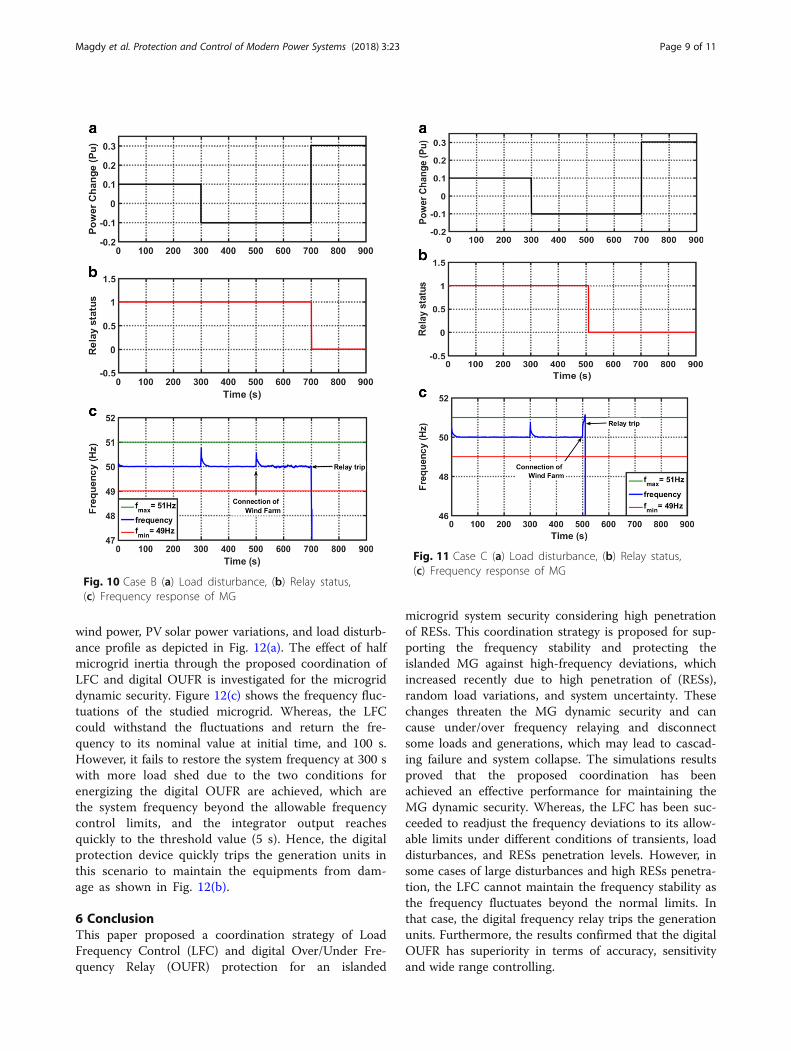
5.3 Scenario CIn this scenario, the dynamic security of the islandedMG with the proposed coordination strategy is evalu-ated under variation in wind power penetration levels(i.e., 25%, 30%, and 35% pu), which are tested respect-ively at time t = 500 s. Moreover, the load disturb-ance profile of scenario (B) is applied to the studiedMG as in Fig. 11(a).The secondary control (i.e., LFC) can restore the fre-
quency to its steady-state value at the first load disturb-ance at time t = 300 s, while it cannot withstand thechange of system frequency caused by high wind pene-tration (i.e., 35% pu) as noted in Fig. 11(c). Therefore,the digital OUFR sent a trip signal to the generator cir-cuit breaker at that time as shown in Fig. 11(b), whereasthe integrator output exceeds the threshold value of 5 s.Hence, the effectiveness of the proposed coordination isapproved for the MG dynamic security.
5.4 Scenario DThe islanded MG is assumed to have the defaultparameters and the microgrid is estimated under thesituation of half of default system inertia (50% of defaultsystem inertia) with multiple operation conditions of
Fig. 8 Multiple disturbances in wind power and solarirradiation power
start
Measuring theSystem Frequency
(f)
fmax< f <fmin
Yes
f > fmax
No
No
EnergizeOver/Under Frequency
Relay
Trip Signal to C.B
stop
Yes
f < fmin
Yes
IntegratorK>5
No
Yes
No
f withinthe normal
limits(±0.1Hz)
Yes
No
Control Action(LFC)
Fig. 7 Flowchart of the proposed coordination
Fig. 9 Case A (a) Load disturbance, (b) Relay status,(c) Frequency response of MG
Magdy et al. Protection and Control of Modern Power Systems (2018) 3:23 Page 8 of 11
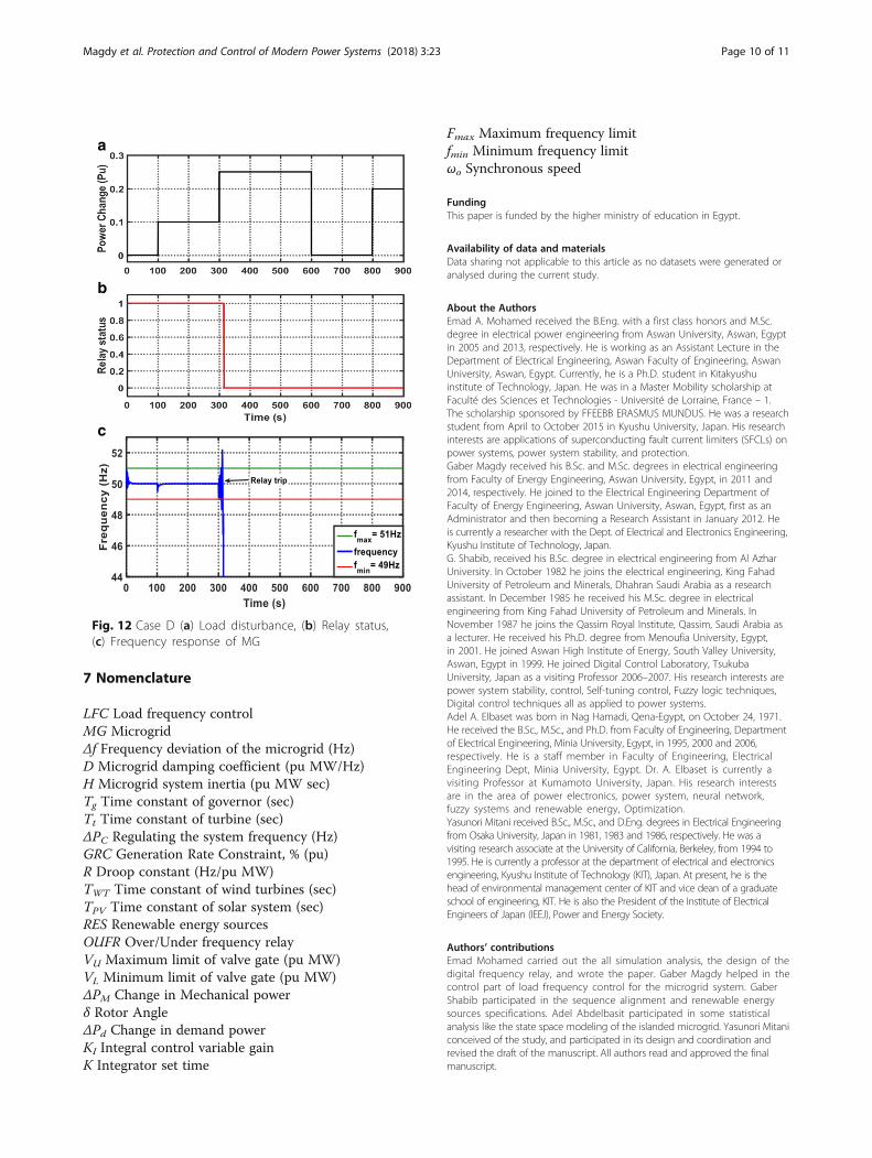
wind power, PV solar power variations, and load disturb-ance profile as depicted in Fig. 12(a). The effect of halfmicrogrid inertia through the proposed coordination ofLFC and digital OUFR is investigated for the microgriddynamic security. Figure 12(c) shows the frequency fluc-tuations of the studied microgrid. Whereas, the LFCcould withstand the fluctuations and return the fre-quency to its nominal value at initial time, and 100 s.However, it fails to restore the system frequency at 300 swith more load shed due to the two conditions forenergizing the digital OUFR are achieved, which arethe system frequency beyond the allowable frequencycontrol limits, and the integrator output reachesquickly to the threshold value (5 s). Hence, the digitalprotection device quickly trips the generation units inthis scenario to maintain the equipments from dam-age as shown in Fig. 12(b).
6 ConclusionThis paper proposed a coordination strategy of LoadFrequency Control (LFC) and digital Over/Under Fre-quency Relay (OUFR) protection for an islanded
microgrid system security considering high penetrationof RESs. This coordination strategy is proposed for sup-porting the frequency stability and protecting theislanded MG against high-frequency deviations, whichincreased recently due to high penetration of (RESs),random load variations, and system uncertainty. Thesechanges threaten the MG dynamic security and cancause under/over frequency relaying and disconnectsome loads and generations, which may lead to cascad-ing failure and system collapse. The simulations resultsproved that the proposed coordination has beenachieved an effective performance for maintaining theMG dynamic security. Whereas, the LFC has been suc-ceeded to readjust the frequency deviations to its allow-able limits under different conditions of transients, loaddisturbances, and RESs penetration levels. However, insome cases of large disturbances and high RESs penetra-tion, the LFC cannot maintain the frequency stability asthe frequency fluctuates beyond the normal limits. Inthat case, the digital frequency relay trips the generationunits. Furthermore, the results confirmed that the digitalOUFR has superiority in terms of accuracy, sensitivityand wide range controlling.
Fig. 10 Case B (a) Load disturbance, (b) Relay status,(c) Frequency response of MG
Fig. 11 Case C (a) Load disturbance, (b) Relay status,(c) Frequency response of MG
Magdy et al. Protection and Control of Modern Power Systems (2018) 3:23 Page 9 of 11
7 Nomenclature
LFC Load frequency controlMG MicrogridΔf Frequency deviation of the microgrid (Hz)D Microgrid damping coefficient (pu MW/Hz)H Microgrid system inertia (pu MW sec)Tg Time constant of governor (sec)Tt Time constant of turbine (sec)ΔPC Regulating the system frequency (Hz)GRC Generation Rate Constraint, % (pu)R Droop constant (Hz/pu MW)TWT Time constant of wind turbines (sec)TPV Time constant of solar system (sec)RES Renewable energy sourcesOUFR Over/Under frequency relayVU Maximum limit of valve gate (pu MW)VL Minimum limit of valve gate (pu MW)ΔPM Change in Mechanical powerδ Rotor AngleΔPd Change in demand powerKI Integral control variable gainK Integrator set time
Fmax Maximum frequency limitfmin Minimum frequency limitωo Synchronous speed
FundingThis paper is funded by the higher ministry of education in Egypt.
Availability of data and materialsData sharing not applicable to this article as no datasets were generated oranalysed during the current study.
About the AuthorsEmad A. Mohamed received the B.Eng. with a first class honors and M.Sc.degree in electrical power engineering from Aswan University, Aswan, Egyptin 2005 and 2013, respectively. He is working as an Assistant Lecture in theDepartment of Electrical Engineering, Aswan Faculty of Engineering, AswanUniversity, Aswan, Egypt. Currently, he is a Ph.D. student in Kitakyushuinstitute of Technology, Japan. He was in a Master Mobility scholarship atFaculté des Sciences et Technologies - Université de Lorraine, France – 1.The scholarship sponsored by FFEEBB ERASMUS MUNDUS. He was a researchstudent from April to October 2015 in Kyushu University, Japan. His researchinterests are applications of superconducting fault current limiters (SFCLs) onpower systems, power system stability, and protection.Gaber Magdy received his B.Sc. and M.Sc. degrees in electrical engineeringfrom Faculty of Energy Engineering, Aswan University, Egypt, in 2011 and2014, respectively. He joined to the Electrical Engineering Department ofFaculty of Energy Engineering, Aswan University, Aswan, Egypt, first as anAdministrator and then becoming a Research Assistant in January 2012. Heis currently a researcher with the Dept. of Electrical and Electronics Engineering,Kyushu Institute of Technology, Japan.G. Shabib, received his B.Sc. degree in electrical engineering from Al AzharUniversity. In October 1982 he joins the electrical engineering, King FahadUniversity of Petroleum and Minerals, Dhahran Saudi Arabia as a researchassistant. In December 1985 he received his M.Sc. degree in electricalengineering from King Fahad University of Petroleum and Minerals. InNovember 1987 he joins the Qassim Royal Institute, Qassim, Saudi Arabia asa lecturer. He received his Ph.D. degree from Menoufia University, Egypt,in 2001. He joined Aswan High Institute of Energy, South Valley University,Aswan, Egypt in 1999. He joined Digital Control Laboratory, TsukubaUniversity, Japan as a visiting Professor 2006–2007. His research interests arepower system stability, control, Self-tuning control, Fuzzy logic techniques,Digital control techniques all as applied to power systems.Adel A. Elbaset was born in Nag Hamadi, Qena-Egypt, on October 24, 1971.He received the B.Sc., M.Sc., and Ph.D. from Faculty of Engineering, Departmentof Electrical Engineering, Minia University, Egypt, in 1995, 2000 and 2006,respectively. He is a staff member in Faculty of Engineering, ElectricalEngineering Dept, Minia University, Egypt. Dr. A. Elbaset is currently avisiting Professor at Kumamoto University, Japan. His research interestsare in the area of power electronics, power system, neural network,fuzzy systems and renewable energy, Optimization.Yasunori Mitani received B.Sc., M.Sc., and D.Eng. degrees in Electrical Engineeringfrom Osaka University, Japan in 1981, 1983 and 1986, respectively. He was avisiting research associate at the University of California, Berkeley, from 1994 to1995. He is currently a professor at the department of electrical and electronicsengineering, Kyushu Institute of Technology (KIT), Japan. At present, he is thehead of environmental management center of KIT and vice dean of a graduateschool of engineering, KIT. He is also the President of the Institute of ElectricalEngineers of Japan (IEEJ), Power and Energy Society.
Authors’ contributionsEmad Mohamed carried out the all simulation analysis, the design of thedigital frequency relay, and wrote the paper. Gaber Magdy helped in thecontrol part of load frequency control for the microgrid system. GaberShabib participated in the sequence alignment and renewable energysources specifications. Adel Abdelbasit participated in some statisticalanalysis like the state space modeling of the islanded microgrid. Yasunori Mitaniconceived of the study, and participated in its design and coordination andrevised the draft of the manuscript. All authors read and approved the finalmanuscript.
a
b
c
Fig. 12 Case D (a) Load disturbance, (b) Relay status,(c) Frequency response of MG
Magdy et al. Protection and Control of Modern Power Systems (2018) 3:23 Page 10 of 11

Competing interestsThe authors declare that they have no competing interests.
Author details1Department of Electrical Engineering, Kyushu Institute of Technology,Tobata-Ku, Kitakyushu-shi, Fukuoka 804-8550, Japan. 2Department ofElectrical Engineering, Faculty of Energy Engineering, Aswan University,Aswan 81528, Egypt. 3Higher Institute of Engineering and Technology, KingMarriott, Alexandria 23713, Egypt. 4Department of Electrical Engineering,Faculty of Engineering, Minia University, Minia 61517, Egypt.
Received: 15 February 2018 Accepted: 31 May 2018
References1. Belwin, J. (2017). Brearley and R. Raja Prabu, “a review on issues and
approches for microgrid protection”. Journal of Renewable and SustainableEnergy Reviews, 67, 988–997.
2. Dong, Y., Xie, X., Wang, K., & Jiang, Q. (2017). An emergency-demand-response based under speed load shedding scheme to improve short-termvoltage stability. IEEE Transactions on Power Systems, 32(5), 3726–3735.
3. Aristidou, P., Valverde, G., & Cutsem, T. V. (2017). Contribution of distributionnetwork control to voltage stability: A case study. IEEE Transactions on SmartGrid, 8(1), 106–116.
4. Bevrani, H., Watanabe, M., & Mitani, Y. (2014). Power system monitoring andcontrol. New Jersey: Wiley.
5. Rakhshani, E., Remon, D., Cantarella, A., & Rodriguez, P. (2016). Analysis ofderivative control based virtual inertia in multi-area high-voltage directcurrent interconnected power systems. IET Generation, Transmission &Distribution, 10(6), 1458–1469.
6. Bevrani, H., Ise, T., & Miura, Y. (2014). Virtual synchronous generators: Asurvey and new perspectives. International Journal of Electrical Power &Energy Systems, 54, 244–254.
7. Sortomme, E., Venkata, S. S., & Mitr, J. (2010). Microgrid protection usingcommunication-assisted digital relays. IEEE Transactions on Power Delivery,25(4), 2789–2796.
8. Zamani, M. A., Sidhu, T. S., & Yazdani, A. (2011). A protection strategy andmicroprocessor-based relay for low-voltage micro-grids. IEEE Transactions onPower Delivery, 26(3), 1873–1883.
9. Keil, T., & Jager, J. (2008). Advanced coordination method for over-currentprotection relays using nonstandard tripping characteristics. IEEETransactions on Power Delivery, 23(1), 52–57.
10. A. Singh, and Sathans, "GA optimized PID controller for frequencyregulation in standalone AC microgrid”, IEEE conf, 7th India InternationalConference on Power Electronics (IICPE), 17–19 Novomber 2016.
11. G. Parise, L. Martirano, M. Kermani, and M. Kermani, “Designing a powercontrol strategy in a microgrid using PID / fuzzy controller based on batteryenergy storage”, IEEE International Conference on Environment andElectrical Engineering and 2017 IEEE Industrial and Commercial PowerSystems Europe (EEEIC / I&CPS Europe), 13 2017.
12. Bevrani, H., Habibi, F., Babahajyani, P., Watanabe, M., & Mitani, Y. (2012).Intelligent frequency control in an AC microgrid:Online PSO-based fuzzytuning approach. IEEE Transactions on Smart Grid, 3(4).
13. Kang Gong, Jing Shi, Yang Liu, Zuoshuai Wang, Li Ren, and Yi Zhang, “Application of SMES in the micro-grid based on fuzzy control”, IEEETransactions on Applied Superconductivity, Vol. 26, No. 3, 2016.
14. Kerdphol, T., Rahman, F. S., Mitani, Y., Watanabe, M., & Küfeoğlu, S. (2018).Robust virtual inertia control of an islanded microgrid considering highpenetration of renewable energy. IEEE Access, 6(1), 625–636.
15. Yi Han, A. Jain, P. Young, and D. Zimmerle, “Robust Control of MicrogridFrequency with Attached Storage System”, 52nd IEEE Conference onDecision and Control, 10–13 December, Florence, Italy, 2013.
16. Tang, X., Hu, X., Li, N., Deng, W., & Zhang, G. (2016). A novel frequency andvoltage control method for islanded microgrid based on multienergystorages. IEEE Transactions on Smart Grid, 7(1), 410–419.
17. L. Sedghi and A. Fakharian, “Voltage and frequency control of an islandedmicrogrid through robust control method and fuzzy droop technique”, 5thIranian Joint Congress on Fuzzy and Intelligent System (CFIS), Qazvin IslamicAzad University, Tehran, Iran, 7–9 March, 2017.
18. Pahasa, J., & Ngamroo, I. (2016). Coordinated control of wind turbine bladepitch angle and PHEVs using MPCs for load frequency control of microgrid.IEEE Systems Journal, 10(1), 97–105.
19. Y. Wang, H. P. Painemal, K. Sun, “Online analysis of voltage security in amicrogrid using convolutional neural networks,” IEEE Conf, Power & EnergySociety General Meeting, Chicago, USA, 2017.
20. Meier, S., & Kunsman, S. (2016). Protection and control system impacts fromthe digital world. Electric Energy T&D Magazine, 12–15. http://www.electricenergyonline.com/show_article.php?mag=117&article=996
21. Sortomme, E., Mapes, G. J., Foster, S., & Venkata, S. (2009). Fault analysis andprotection of a micro-grid. IEEE Transactions on Power Delivery, 24(3), 1045–1053.
22. Sheng, S., Li, K. K., Chan, W. L., Zeng, X., Shi, D., & Duan, X. (2010). Adaptiveagent-based wide-area current differential protection system. IEEETransactions on Industry Applications, 46(5), 2111–2117.
23. Laghari, J. A., Mokhlis, H., Bakar, A. H. A., & Mohamad, H. (2013). Applicationof computational intelligence techniques for load shedding in powersystems: A review. Energy Conversion and Management, 75, 130–140.
24. Komsan Hongesombut, Naowarat Tephiruk, “Modeling of the rate ofchange of under-frequency relay for microgrid protection”, InternationalElectrical Engineering Congress (iEECON), 2017, 1–4.
25. Freitas, W., Xu, W., Affonso, C. M., & Huang, Z. (2005). Comparative analysisbetween ROCOF and vector surge relays for distributed generationapplications. IEEE Transactions, 20(2), 1315–1324.
26. Teimourzadeh, S., Aminifar, F., Davarpanah, M., & Shahidehpour, M. (2017).Adaptive protection for preserving microgrid security. IEEE Transactions onSmart Grid, (99), 1–9.
27. Vieira, J. C. M., Freitas, W., Xu, W., & Morelato, A. (2006). Efficient coordinationof ROCOF and frequency relays for distributed generation protection byusing the application region. IEEE Transactions on Power Delivery, 21(4),1878–1884.
28. Teimourzadeh, S., Aminifar, F., & Davarpanah, M. (2017). Microgrid dynamicsecurity: Challenges, solutions and key considerations. The Electricity Journal,30(1), 43–51.
29. Bevrani, H. (2014). Robust power system frequency control (2nd ed.).Gewerbestrasse: Springer.
30. Hassan, A. A. M., & Kandeel, T. A. (2015). Effectiveness of frequency relays onnetworks with multiple distributed generation. Journal of Electrical Systemsand Information Technology, 2, 75–85.
31. Zarei, S. F., & Parniani, M. (2017). A comprehensive digital protection schemefor low-voltage micro grids with inverter-based and conventionaldistributed generations. IEEE Transactions on Power Delivery, 32(1), 441–452.
Magdy et al. Protection and Control of Modern Power Systems (2018) 3:23 Page 11 of 11