Embed Size (px)
Citation preview

1 Watlow MicroDIN Quick Star t Guide
Communicating Subpanel Temperature Controller
0600-0011-0002 Rev B
February 2003 $5.00
MicroDIN Quick Start Guide
Watlow Winona1241 Bundy Blvd., P.O. Box 5580, Winona, MN 55987-5580Phone: (507) 454-5300, Fax: (507) 452-4507www.watlow.com

2 Watlow MicroDIN Quick Start Guide
Introduction to the MicroDIN ControllerThe Watlow MicroDIN controller is a DIN rail-mounted, temperature controller.It uses one input and two outputs, network connections and dozens of parame-ters to satisfy a broad variety of control needs.
The single input can use either a thermocouple or RTD sensor. The single con-trol output provides an open collector or switched dc output signal for a powerswitching device with a DC input. The single alarm output is an electromechani-cal relay. The network connections allow as many as 32 controllers to be config-ured and monitored from a single personal computer.
You can configure, operate and monitor the MicroDIN almost entirely from aPLC or personal computer via a serial connection using RJ-11 jacks. Indicatorlights on the face of the controller monitor error states, power, communicationsactivity and output activity.
Figure 2 - MicroDINinputs and outputs in athermal system
Address
Power
Comms
Alarm
Temperature Controller
MicroDINTemperature Controller
MicroDIN
ControlOutput
InputError
Address
Power
Comms
Alarm
Temperature Controller
MicroDINTemperature Controller
MicroDIN
ControlOutput
InputError
Address
Power
Comms
Alarm
Temperature Controller
MicroDINTemperature Controller
MicroDIN
ControlOutput
InputError
Address
Power
Comms
Alarm
Temperature Controller
MicroDINTemperature Controller
MicroDIN
ControlOutput
InputError
1 2 3 4
Communications Input and Outputto and from Personal Computer
Per Unit:• Sensor Input from the process• Control Output to the process• Alarm Output about the process
1-32 devices/EIA-485 Network
Note: An electronic copy of this MicroDIN Quick Start Guide and the full versionMicroDIN User’s Manual is available at www.watlow.com/prodtechinfo. Search onkeyword MicroDIN.

3 Watlow MicroDIN Quick Start Guide
Setup Steps1. Set up communications.
2. Set the controller’s address and baud speed with the DIP switches on the toppanel (see page 6). The controller uses eight data bits with no parity.
3. Mount the controller (see pages 9 and 10).
4. Wire the controller (see pages 12-14).
5. Communicate with MicroDIN via an EIA-485 network with Modbus™
RTU protocol.
CommunicationsGreen Light pulsates when thecontroller sends or receivesvalid data over its network port.• If it does not light up, checkthe controller address and thecommunications setup.
Input ErrorRed Light is lit if there is a sen-sor problem. If it is lit:• Verify the sensor wiring,polarity and function.• Rewire or replace as neces-sary.
Address FieldRecord the unit’s address inerasable marker here.
Address
Power
Comms
Alarm
Temperature Controller
MicroDINTemperature Controller
MicroDIN
ControlOutput
InputError
Figure 3 - MicroDINindicator lights
Indicator LightsPowerGreen light stayslit when the power is onand the controller is ok.• If it isn’t on or pulsates,check your power source.
Control OutputGreen light is lit or flasheswhen the control output isenergized.• If it does not light up, theoutput is not turning on.
AlarmRed Light is lit during aninput alarm condition.If it is lit:• Correct alarm conditionor change alarm configura-tion.• Reset the alarm if it islatched.

4 Watlow MicroDIN Quick Start Guide
Communications Overview
EIA-485 Network
The MicroDIN uses the EIA-485 (formerly, “RS-485”) hardware interface to com-municate with three wires in a half-duplex configuration, up to 32 remotedevices with a master unit on a network up to 4,000 feet long using 14-26 gaugewire.
Modbus™ Protocol
The MicroDIN uses Modbus™ RTU protocol to read and write to registers thatcan be viewed or changed from a personal computer. Each MicroDIN ‘parameter’has a corresponding Modbus™ register and access privileges. The MicroDIN para-meter register numbers and the order of priority appear later in this chapter.Chapter 5 details all the MicroDIN parameters, and the Appendix provides infor-mation on how to write custom Modbus™ applications
Set Address/Baud Rate
You must configure the communications speed and network address of theMicroDIN controller with the eight-bit DIP switch on the top of the unit. Set thecontroller address with the first six switches and the network speed (9,600 or19,200 baud) with the eighth switch. Turn to the DIP switch page 6.
Serial Data Format
The MicroDIN uses the an 8-N-1 data format; 8 data bits, no parity, 1 stop bit,and 1 start bit. See the data format table later in this chapter.
Wiring Tasks
In addition to wiring the controller’s input, outputs and power connections, youmust also wire the EIA-232-to-EIA-485 converter; connect your computer to theMicroDIN, and connect the MicroDIN communications daisy chain. See“Communications Wiring” on pages 14 and 15.
Communications Software
Watlow offers a Windows application for MicroDIN, called, WATVIEWTM whichwill both set up and run multiple MicroDINs over an EIA-485 network using theModbus™ protocol. For more information on WATVIEWTM, , go to www.watlow.com/products/software.
You may also write your own application (see Appendix for more detail), or pur-chase any of several available Modbus-capable control software packages.
5 Watlow MicroDIN Quick Start Guide
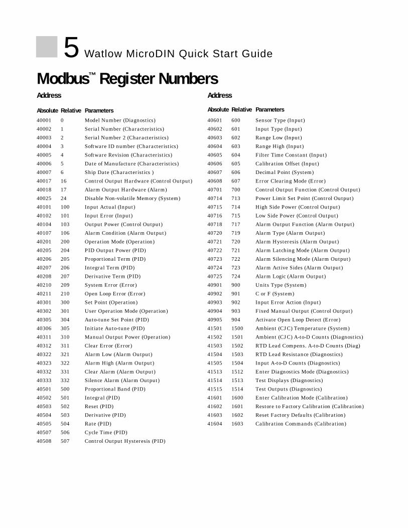
Modbus™ Register Numbers
40001 0 Model Number (Diagnostics)
40002 1 Serial Number (Characteristics)
40003 2 Serial Number 2 (Characteristics)
40004 3 Software ID number (Characteristics)
40005 4 Software Revision (Characteristics)
40006 5 Date of Manufacture (Characteristics)
40007 6 Ship Date (Characteristics )
40017 16 Control Output Hardware (Control Output)
40018 17 Alarm Output Hardware (Alarm)
40025 24 Disable Non-volatile Memory (System)
40101 100 Input Actual (Input)
40102 101 Input Error (Input)
40104 103 Output Power (Control Output)
40107 106 Alarm Condition (Alarm Output)
40201 200 Operation Mode (Operation)
40205 204 PID Output Power (PID)
40206 205 Proportional Term (PID)
40207 206 Integral Term (PID)
40208 207 Derivative Term (PID)
40210 209 System Error (Error)
40211 210 Open Loop Error (Error)
40301 300 Set Point (Operation)
40302 301 User Operation Mode (Operation)
40305 304 Auto-tune Set Point (PID)
40306 305 Initiate Auto-tune (PID)
40311 310 Manual Output Power (Operation)
40312 311 Clear Error (Error)
40322 321 Alarm Low (Alarm Output)
40323 322 Alarm High (Alarm Output)
40332 331 Clear Alarm (Alarm Output)
40333 332 Silence Alarm (Alarm Output)
40501 500 Proportional Band (PID)
40502 501 Integral (PID)
40503 502 Reset (PID)
40504 503 Derivative (PID)
40505 504 Rate (PID)
40507 506 Cycle Time (PID)
40508 507 Control Output Hysteresis (PID)
40601 600 Sensor Type (Input)
40602 601 Input Type (Input)
40603 602 Range Low (Input)
40604 603 Range High (Input)
40605 604 Filter Time Constant (Input)
40606 605 Calibration Offset (Input)
40607 606 Decimal Point (System)
40608 607 Error Clearing Mode (Error)
40701 700 Control Output Function (Control Output)
40714 713 Power Limit Set Point (Control Output)
40715 714 High Side Power (Control Output)
40716 715 Low Side Power (Control Output)
40718 717 Alarm Output Function (Alarm Output)
40720 719 Alarm Type (Alarm Output)
40721 720 Alarm Hysteresis (Alarm Output)
40722 721 Alarm Latching Mode (Alarm Output)
40723 722 Alarm Silencing Mode (Alarm Output)
40724 723 Alarm Active Sides (Alarm Output)
40725 724 Alarm Logic (Alarm Output)
40901 900 Units Type (System)
40902 901 C or F (System)
40903 902 Input Error Action (Input)
40904 903 Fixed Manual Output (Control Output)
40905 904 Activate Open Loop Detect (Error)
41501 1500 Ambient (CJC) Temperature (System)
41502 1501 Ambient (CJC) A-to-D Counts (Diagnostics)
41503 1502 RTD Lead Compens. A-to-D Counts (Diag)
41504 1503 RTD Lead Resistance (Diagnostics)
41505 1504 Input A-to-D Counts (Diagnostics)
41513 1512 Enter Diagnostics Mode (Diagnostics)
41514 1513 Test Displays (Diagnostics)
41515 1514 Test Outputs (Diagnostics)
41601 1600 Enter Calibration Mode (Calibration)
41602 1601 Restore to Factory Calibration (Calibration)
41603 1602 Reset Factory Defaults (Calibration)
41604 1603 Calibration Commands (Calibration)
Address
Absolute Relative Parameters
Address
Absolute Relative Parameters

6 Watlow MicroDIN Quick Start Guide
MicroDIN DIP Switches Set Address/Baud RateConfigure the communications speed and network address of the MicroDIN con-troller with the eight-bit DIP switch on the top panel. Set the controller addresswith the first six switches. Set an address between 1 and 63. The network willnot work correctly if any two controllers have the same address. DIP switch 1sets the left-most binary digit. Switch 6 sets the right-most digit.
Record the MicroDIN’s address in erasable markeron the white space on the front of the unit.
The seventh switch has no effect.
Set the network speed (9,600 or 19,200 baud) with the eighth switch.
Figure 6 - MicroDIN top view withDIP switches and baudsettings
ON↑
1 2 3 4 5 6 7 8
Top View
ON↑
1 2 3 4 5 6 7 8
ON↑
1 2 3 4 5 6 7 8
9600 baud(bit 8 on)
19.2k baud(bit 8 off)
Table 6 - Decimal-to-binary con-version
Dec. Binary1 0000012 0000103 0000114 0001005 0001016 0001107 0001118 0010009 00100110 00101011 00101112 00110013 00110114 00111015 001111
Dec. Binary16 01000017 01000118 01001019 01001120 01010021 01010122 01011023 01011124 01100025 01100126 01101027 01101128 01110029 01110130 01111031 011111
Dec. Binary32 10000033 10000134 10001035 10001136 10010037 10010138 10011039 10011140 10100041 10100142 10101043 10101144 10110045 10110146 10111047 101111
Dec. Binary48 11000049 11000150 11001051 11001152 11010053 11010154 11011055 11011156 11100057 11100158 11101059 11101160 11110061 11110162 11111063 111111
ON↑
1 2 3 4 5 6 7 8ON↑
1 2 3 4 5 6 7 8ON↑
1 2 3 4 5 6 7 8ON↑
1 2 3 4 5 6 7 8

7 Watlow MicroDIN Quick Start Guide
Units TypeC or FInput Error ActionControl Output FunctionSet Fixed Manual Output OOpen Loop DetectSensor TypeInput Type ORange Low C D D CRange High C D D CDecimal Point D DCalibration Offset C D D CFilter Time Constant D DError Clearing ModePower Limit Set Point C D D CHigh Side Power OLow Side Power OAlarm Output FunctionAlarm Type D DAlarm Hysteresis C D D CAlarm Latching ModeAlarm Silencing ModeAlarm Active SidesAlarm LogicAlarm High C D D O CAlarm Low C D D O CPropband C D D CIntegral OReset ODerivativeRateCycle TimeOutput Hysteresis C D D COperation ModeSet PointManual Output Power O O O OSet Point C D D O O C
Uni
ts T
ype
C o
r FC
ontro
l Out
put F
unct
ion
Sen
sor T
ype
Inpu
t Typ
eR
ange
Low
Ran
ge H
igh
Hig
h S
ide
Pow
erLo
w S
ide
Pow
erA
larm
Typ
eO
pera
tion
Mod
eD
ecim
al
Table 7 - Parameters Setup order
Changing this Affects this
Document your settings below
Required Parameters Setup OrderThis table provides 1) the correct order of entry, 2) the effect of a parameter change, and 3) a place to document settings.
Key: D = Changing will change the
defaultC = Changing will convert the tem-
perature scaleO = Other effect (see Ch. 5)
çCAUTION:Parametersshould be setup in this order.

8 Watlow MicroDIN Quick Start Guide
Serial Data FormatConfigure your computer’s COM1 or COM2 (communications) port data format tomatch the MicroDIN’s settings in the table below.
MicroDIN Installation Wiring TasksMicroDIN requires these wiring tasks for a successful installation
1. Wire MicroDIN sensor input.
2. Wire MicroDIN Output 1, the control output.
3. Wire MicroDIN Output 2, the alarm output.
4. Wire MicroDIN power.
5. Connect the MicroDIN communications daisy chain.
6. Wire the 232-to-485 converter; connect to the computer.
7. If necessary, wire the termination and pull-up/pull-down resistors.
Communications Software
WATVIEWTM
Watlow offers aModbus™ packagein WATVIEW™,software that willset up and runmultipleMicroDINs overan EIA-485network.WATVIEW™ isavailable fromany Watlow salesrepresentative orauthorized dis-tributor. For moreinformation, go towww.watlow.com/products/software. WATVIEW™ can handle up to 32 MicroDIN units.
Other SoftwareTo communicate with MicroDIN, you must use a Modbus™ RTU (remote terminalunit) compatible software package. Sending ASCII commands via a standardserial communication application will not work. Refer to the Appendix in theUser's Manual if you’re writing your own Modbus™ RTU application.
Table 8a - Serial Data Format Data Bits Parity Stop Bit Start Bit
8 None 1 1
Figure 8b - WATVIEW™ sample soft-ware screen

9 Watlow MicroDIN Quick Start Guide
Mounting the MicroDINTo mount a MicroDIN on a DIN rail, hook the upper lip of the rail mountingbracket onto the rail and press the controller down until the bottom lip of themount snaps onto the rail. To remove, as you push the back of the controllerdown lift the front up until the bottom lip unsnaps from the rail.
To mount a MicroDIN on a panel, use the dimensions below to drill screw holesfor the mounting bracket.
DINrail
bracket for panel mounting
(#6 screwor m3.5 required)
Side View
Front View
.318 in(8 mm)
Address
Power
Comms
Alarm
Temperature Controller
MicroDINTemperature Controller
MicroDIN
ControlOutput
InputError
3.750 in(146 mm)
2.875 in(73 mm)
5.062 in(129 mm)
Attachment Angle 10°
DINrail
4.225 in(107 mm)
4.650 in(118 mm)
Address
Power
Comms
Alarm
Temperature Controller
MicroDINTemperature Controller
MicroDIN
ControlOutput
InputError
Address
Power
Comms
Alarm
Temperature Controller
MicroDINTemperature Controller
MicroDIN
ControlOutput
InputError
Min. Clearance 2 in(51 mm)
Min. Clearancebetween railcenterlines
5.750 in(146 mm)
1.637 in(42 mm)
1.650 in(42 mm)
Top/bottommounthole offset
Figure 9 - Mounting aMicroDIN controller
çCAUTION:Maintain the correctspacing between rows ofcontrollers to allow suffi-cient air circulation andinstallation clearance.Failure to do so couldresult in damage toequipment.
Use DIN EN 50022 35mm x 7.5mm Rail

10 Watlow MicroDIN Quick Start Guide
Mounting the MicroDIN on a DIN railTo Mount MicroDIN1. Push unit in and down to catch rail hook
on top of rail.
2. Rotate bottom of unit in toward rail.
3. Rail clasp will audibly “snap” into place.If the MicroDIN does not snap into place,check to see if the rail is bent.
To Dismount MicroDIN1. Press down on back of controller until the
bottom hook clears the rail.
2. Then rotate bottom up and away fromrail.
Figure 10a - Mounting a MicroDIN
controller on a DIN rail
Figure 10b- Dismounting a MicroDINcontroller from a DIN rail
①
①
➁
➂ "Snap"➁

11 Watlow MicroDIN Quick Start Guide
MicroDIN RJ-11 and 10-pin ConnectorsThe MicroDIN 10-pin screw terminal connector, on the bottom of the case, linksit to its power supply, control input, control output and alarm output. Use 26- to14-gauge wire to connect to the plug terminals.
The alarm output is an electromechanical relay.
See the Appendix for information on sensor ranges and specifications. SeeChapter 5: Parameters for information about software configuration.
1 2 3 4 5 6 7 8 9 10
Input1. S1 or thermocouple+2. S3 or thermocouple-3. S2
Control Output4. dc+5. dc-6. common (COM)
Alarm Output (electromechanical relay)7. alarm normally open (NO)8. alarm common (COM)
Power9. L2, 24V‡ (ac/dc)-10. L1, 24V‡ (ac/dc)+
Figure 11 - Bottom viewof MicroDIN case withconnector assignments
communications sockets 1 and 2
(RJ-11)
1 2 3 4 5 6 7 8 9 10
10-pin removable connector
Front of UnitÓWARNING:To avoid potential elec-tric shock, use NationalElectric Code (NEC) safe-ty practices when wiringand connecting this unitto a power source and toelectrical sensors orperipheral devices.Failure to do so couldresult in injury or death.
çWARNING:Install high or low tem-perature limit control pro-tection in systems wherean over temperature faultcondition could present afire hazard or other haz-ard. Failure to installtemperature limit controlprotection where a poten-tial hazard exists couldresult in damage toequipment and propertyand injury to personnel.
Bottom View
ABCD

12 Watlow MicroDIN Quick Start Guide
Input Wiring
1 2 3 4 5 6 7 8 9 10
+ -
1 2 3 4 5 6 7 8 9 10
S1 S3
1 2 3 4 5 6 7 8 9 10
S1 S2
S3
Figure 12b — Control Input, Thermocouple
Figure 12a — MicroDIN Isolation Diagram
Figure 12c — Control Input, 2-wire RTD
Figure 12d — Control Input, 3-wire RTD
Power Supply
Logicand
InputOutputs
500VNoiseIsolation
Safety Isolation UL/CE
ControlOutput
Alarm
Comms

13 Watlow MicroDIN Quick Start Guide
Output and Power Wiring
1 2 3 4 5 6 7 8 9 10
+
ExternalLoad
-
dc+
COMdc
-
+
- Power Supply
42V max.1A max.
1 2 3 4 5 6 7 8 9 10
ExternalLoad
COMN.O
.
RelaySuppression
Fuse L1
L2
+24VÎ(dc)
Internal Circuitry
20Ω
2KΩ
4dc+
5dc-
6COM
101 2 3 4 5 6 7 8 9
24V‡ (ac/dc)- +
Figure 13c — Internal Output Circuitry
Figure 13d — Alarm Output
Figure 13b — Control Output, Open Collectorwith External Power Supply
Figure 3.4e — Power Wiring
ÓWARNING:To avoid potential elec-tric shock, use NationalElectric Code (NEC) safe-ty practices when wiringand connecting this unitto a power source and toelectrical sensors orperipheral devices.Failure to do so couldresult in injury or death.
1 2 3 4 5 6 7 8 9 10
+
ExternalLoad
-
dc+
COMdc
-
Figure 13a — Control Output, Switched DCwith Internal Power Supply
ExternalSwitchingDevice
ExternalSwitching
Device
NOTE:Relay suppressionrequired only for induc-tive loads. Ó
WARNING:If high voltage is appliedto a this 24V controller,irreversible damage willoccur.

14 Watlow MicroDIN Quick Start Guide
Communications Wiring
Address
Power
Comms
Alarm
Temperature Controller
MicroDINTemperature Controller
MicroDIN
ControlOutput
InputError
Address
Power
Comms
Alarm
Temperature Controller
MicroDINTemperature Controller
MicroDIN
ControlOutput
InputError
Address
Power
Comms
Alarm
Temperature Controller
MicroDINTemperature Controller
MicroDIN
ControlOutput
InputError
Address
Power
Comms
Alarm
Temperature Controller
MicroDINTemperature Controller
MicroDIN
ControlOutput
InputError
1 2 3 4
Figure 14a- MicroDINcommunications daisychain via RJ-11connectors
Converter-To-MicroDIN Wiring Example
Note: If your networkdoesn’t function, seeSpecial 485 NetworkConsiderations section.
Green
RJ-11 to MicroDIN
TD (A)TD (B)RD (A)RD (B)
SIG GND
TD (A)TD (A)
Yellow
120V~
EIA-232
EIA-485 EIA-485Power Supply
AD-1210
+–
CB
AD
Figure 14b- B&BConverter to MicroDINWiring(B&B ElectronicsManufacturing Company,Ph. 815-433-5100)www.bb-elec.com
9ÎVdc (see NOTE)
120VÅ (Vac)
Comms PlugRed
YellowYellow Green
0219-0217-00007 ft. comms cable
EIA
232
AD
A48
5L
EIA
-485
CB
AD
ABABG
9VDCG
DI/O
DI/O
Figure 14c - CMCConverter to MicroDINWiring(CMC Connecticut Micro-Computer, Inc.Ph. 800-426-2872)www.2cmc.com
ÓWARNING:To avoid potential elec-tric shock, use NationalElectric Code (NEC) safe-ty practices when wiringand connecting this unitto a power source and toelectrical sensors orperipheral devices.Failure to do so couldresult in injury or death.
Note: The CMC converter requires an external power supply when used with a laptop.

15 Watlow MicroDIN Quick Start Guide
Special EIA-485 Network ConsiderationsIf your MicroDIN network doesn't work, it may need termination and pull-upand pull-down resistors; wire them per the diagrams below.
Figure 15 a- Terminationfor MicroDIN; RJ-11phone plug with 120Ωresistor across C and D
Figure 15b - Termination forEIA-232/EIA-485Converter with pull-upand pull-down resistors
+5V
B
A
GND
T+/R+
T-/R-
Com
1KΩ
120Ω
1KΩ
Converter boxterminationwith pull-up and pull-down resistors.
ABCD
120Ω
Plug terminator into open socket in MicroDIN controller furthest from computer,the last unit on the network.
RJ-11 TerminalsC (green) and D (yellow)

16 Watlow MicroDIN Quick Start Guide
1
11
4
5
6
7
8
10
11
12
1
11
1
2
23
2 2
2
2
2
2
2
3
7
33
4
5
4
5
9
5
6
6
7
7
8
8
8
9
9
9
10
10
10
11 11
6
+ +
+
5
– –
–
11
18
16
15
14
14 19
17
20 21
12 13
13
High Temp. Light
1
L1
2
L2
43
SemiconductorFuse
Heater
Series 146Limit Control
146E-1601-1000
1 CR
LoopEIA485
1CR-1
PCEIA485
DIN-a-miteDA10-24C0-0000
MicroDINUD1A-1CES-0000
0830-0474-0000Power Supply
120V~(ac)
OptionalNormally OpenMomentarySwitch
2
3
9
Figure 16 -System wiring example,ladder diagram
ÓWARNING:To avoid potential elec-tric shock, use NationalElectric Code (NEC) safe-ty practices when wiringand connecting this unitto a power source and toelectrical sensors orperipheral devices.Failure to do so couldresult in injury or death.
çWARNING:Install high or low tem-perature limit control pro-tection in systems wherean over temperature faultcondition could present afire hazard or other haz-ard. Failure to installtemperature limit controlprotection where a poten-tial hazard exists couldresult in damage toequipment and propertyand injury to personnel.

17 Watlow MicroDIN Quick Start Guide
Wiring Examples
Hightemp.light
146E-1601-1000
Limit ControlHeater
OptionalNormally
OpenMomentary
Switch
DIN-A-MITEDA10-24C0-0000
High LimitMechanicalContactor
BranchCircuit Fuse
SemiconductorFuse
Earth Ground
L1120VÅ (ac)
L2
21
3 4
WatlowMicroDIN
TemperatureController
UD1A-CES-0000
0830-0474-0000Power Supply
ThermocouplesPC
OR ModBusConverter
R
EIA485Loop
EIA485 to RS232Converter
Coil
21 3 4 5 6 7 8 9
21 3 4 5 6 7 8 9 10
1110 121314 151617
65
(-)(+)
(-)(+)
Figure 17 -System wiring example,schematic
ÓWARNING:To avoid potential elec-tric shock, use NationalElectric Code (NEC) safe-ty practices when wiringand connecting this unitto a power source and toelectrical sensors orperipheral devices.Failure to do so couldresult in injury or death.
çWARNING:Install high or low tem-perature limit control pro-tection in systems wherean over temperature faultcondition could present afire hazard or other haz-ard. Failure to installtemperature limit controlprotection where a poten-tial hazard exists couldresult in damage toequipment and propertyand injury to personnel.

MicroDINWatlow Winona, Inc.1241 Bundy Blvd. Winona, MN 55987 USADeclares that the following product:Designation: MicroDINModel Numbers: UD1A – 1CES – (Any four letters or numbers) Classification: Temperature control, Installation Category II, Pollution degree 2Rated Voltage: 24V‡ to 24V‡ (ac or dc) Rated Frequency: 50 or 60 HzRated Power Consumption: 5VA maximum
Meets the essential requirements of the following European Union Directives by using the relevantstandards show below to indicate compliance.
89/336/EEC Electromagnetic Compatibility Directive
EN 61326:1997 A1:1998 Electrical equipment for measurement, control and lab-oratory use – EMC requirements (Industrial Immunity,Class A Emissions).
EN 61000-4-2: 1996 With A1, 1998: Electrostatic Discharge ImmunityEN 61000-4-3: 1997: Radiated Field ImmunityEN 61000-4-4: 1995: Electrical Fast-Transient / Burst ImmunityEN 61000-4-5: 1995 With A1, 1996: Surge ImmunityEN 61000-4-6: 1996: Conducted ImmunityEN 61000-4-11: 1994: Voltage Dips, Short Interruptions and Voltage Variations
ImmunityEN 61000-3-2: 1995 With A1-3:1999: Harmonic Current EmissionsEN 61000-3-3: 1995 With A1:1998: Voltage Fluctuations and Flicker
73/23/EEC Low-Voltage DirectiveEN 61010-1: 1993 With A1:1995: Safety Requirements of electrical equipment for mea-
surement, control and laboratory use. Part 1: Generalrequirements
Raymond D. Feller III Winona, Minnesota, USAName of Authorized Representative Place of Issue
General Manager January 2003Title of Authorized Representative Date of Issue
Signature of Authorized Representative(2348)
Declaration of Conformity
18 Watlow MicroDIN Quick Start Guide

19 Watlow MicroDIN Quick Start Guide
Indication Symptoms Probable Cause(s)
Troubleshooting Alarms and Errors most likely problems are listed first
Power• No power. • Power supply switch off
• Fuse blown• Breaker tripped
Error = off • Safety interlock door switch, etc.• Separate system limit control may be latched
(Normal = • Open wiringsteady green) • Power ≤ 20V‡ (ac/dc)
Communications• Unit will not communicate. • MicroDIN address DIP switch incorrectly set
• MicroDIN baud rate DIP switch incorrectly set• MicroDIN unit-to-unit daisy chain disconnected• Reversed, short or open EIA-485 communications wiring
Error = off • EIA-485 converter box incorrectly wired• Computer COM port incorrectly set up
(Normal = • Communications software setup or address incorrectpulsing green) • Protocol or parity wrong, not 8, n, 1
• Needs termination and pull-up and pull-down resistors
Input Error• Input is in error condition. • The sensor is improperly wired
• Sensor wiring reversed, shorted or open• MicroDIN firmware setting does not = actual sensor• Power ≤ 20V‡ (ac/dc)
Error = steady red • Ambient environmental temperature out of spec for MicroDIN• The MicroDIN open loop detect shows a broken sensor
(Normal = off ) • The calibration offset parameter is set much too high or low
Alarms • Alarm won’t occur. • Alarm output off
• Alarm set points incorrect• Alarm silenced• Alarm sides incorrect
Alarm = steady red • In diagnostics mode• Alarm won’t clear. • Alarm latched
(Normal = off) • Alarm set points incorrect• Alarm hysteresis incorrect• Input in error condition
ErrorsFlashing LED Error 4 • RAM malfunctionIndicator Light Error 5 • EEPROM data corruptedPattern Error 6 • PROM malfunction
Error 7 • Logic hardware problemError 11 • New firmware installed
Error 12 • Calibration data corruptedError 13 • Analog-to-digital hardware failure
Error 14 • EEPROM hardware problemError 15 • New unit first power up

20 Watlow MicroDIN Quick Start Guide
Corrective Action
• Check switches, fuses, breakers, interlocks, limits, connectors, etc. for energized condition and proper connection
• Measure power upstream for required level• Check wire size• Check for bad connections
• Check and reset unit DIP switches 1-6 to correct address• Check and reset unit DIP switch 8 to correct baud rate• Look for a break in the daisy chain• Verify correct connections and test wiring paths• Check converter box wiring and its documentation• Reconfigure computer's COM port setup and verify communications ok• Check the communication card documentation for setable variables, operational testing• Restart COMS software, check for settings agreement. Verify COM bus active
• Check sensor connections• Check sensor connections and sensor wiring• Change the Sensor Type parameter (Input Group) to match the sensor hardware• Measure power upstream for required level• Verify that the temperature surrounding unit is 32° to 149°F (0° to 65°C)• Check sensor function. The Open Loop Detect parameter (Error Group) indicates it may be broken• Check the Calibration Offset parameter (Input Group) value; set it to a lower level
• Send the alarming MicroDIN unit a “clear alarm” signal (Modbus™: 331)Note: The condition causing the alarm must also be resolved for the alarm to clear
• To clear the alarm, correct the alarm condition; check to see if the alarm is latched• Check the alarm sides setting• Check the alarm type setting• Check the alarm logic for compatibility with system peripherals and annunciators• Check the power limit setting• Check the operation mode• Check the alarm output function• Check °F/°C setting• Check the calibration offset value; set it to a lower level
• Return unit to factory• Cycle power to unit• Return unit to factory• Return unit to factory• Cycle power to unit• Recalibrate unit• Return unit to factory• Return unit to factory• Return unit to factory

21 Watlow MicroDIN Quick Start Guide
Specifications: (2346)
Control Mode• Microprocessor-based, user selectable control modes• Single input, single output• Heat or cool auto-tuning
Output #1: User selectable• ON/OFF; P, PI, PD, PID heat or cool action adjustable switching differential:
1 to 9999 or 0.1 to 999.9°F or °C• Proportional band: 0 to 9999, or 0.0 to 999.9°F or °C• Integral: 0.00 to 99.99 minutes per repeat• Reset: 0.00 to 99.99 repeats per minute• Derivative/Rate: 0.00 to 9.99 minutes• Cycle Time: 0.1 to 60.0 seconds
Output #2: User selectable• Process or deviation alarm with flashing alarm status indicator• Alarm with separate high and low set points• Hysteresis: 1 to 9999° switching differential
Operator Interface• EIA-485 serial communications with Modbus™ RTU protocol• 9600, 19200 user selectable baud rates• 1 to 63 user selectable address range
Sensor Input• Sensor input sampling rate: 10 samples/second, 10Hz• Thermocouple, grounded or ungrounded sensors• RTD 2 or 3 wire, platinum, 100Ω@ 0°C calibration to JIS curve (0.003916Ω/Ω/°C), or
DIN curve (0.00385Ω/Ω/°C)• Sensor break protection de-energizes control output to protect system or selectable
bumpless transfer to manual operation.• °F or °C, user selectable• Sensor Ranges:
Accuracy Ranges: Operating RangesB t/c 1598 to 3092°F 870 to 1700°C 32 to 3300°F 0 to 1816°CC (W5) t/c 32 to 4200°F 0 to 2315°C 32 to 4200°F 0 to 2315°CD (W3) t/c 32 to 4200°F 0 to 2315°C 32 to 4200°F 0 to 2315°CE t/c -328 to 1472°F -200 to 800°C -328 to 1470°F -200 to 800°CJ t/c 32 to 1382°F 0 to 750°C 32 to 1500°F 0 to 815°CK t/c -328 to 2282°F -200 to 1250°C -328° to 2500°F -200 to 1370°CN t/c 32 to 2282°F 0 to 1250°C 32 to 2372°F 0 to 1300°CPT2 t/c 32 to 2540°F 0 to 1393°C 32 to 2543°F 0 to 1395°CR t/c 32 to 2642°F 0 to 1450°C 32 to 3200°F 0 to 1760°CS t/c 32 to 2642°F 0 to 1450°C 32 to 3200°F 0 to 1760°CT t/c -328 to 662°F -200 to 350°C -328 to 750°F -200 to 400°C1.0 RTD (DIN) -328 to 1202°F -200 to 650°C -328 to 1472°F -200 to 800°C0.1 RTD (JIS) -199.9 to 999.9°F -143 to 636°C -328 to 1166°F -200 to 630°C
• Tenth degree resolution selectable over sensor operating range within limits of -199.9 to 999.9, except for thermocouple types B, R, and S

22 Watlow MicroDIN Quick Start GuidePrimary Control Output (heating or cooling)
• Output update rate: 10 per second, 10Hz (maximum)Internal Load Switching (nominal):Switched dc (isolated) signal, 22 to 28VÎ (Vdc), current limited @ 30mAOverload current and short circuit protectionExternal Load Switching (maximum):
• Open Collector 42VÎ (Vdc) @ 1A
Alarm Output• Output update rate 2 per second (2Hz)• Electromechanical relay, Form A, 2A @ 30VÎ (Vdc) or 240VÅ(Vac),• Alarm output can be latching or non-latching, and process or deviation with sepa-
rate high and low values. Alarm silencing (inhibit) on power-up.
Accuracy• Calibration accuracy and sensor conformity: ±0.1% of span ±1°C @ 25°C ±3°C (77°F
±5°F ) ambient, and rated line voltage ±10% with the following exceptions:Type T; 0.12% of span for -200°C to -50°CTypes R and S; 0.15% of span for 0°C to 100°CType B; 0.24% of span for 870°C to 1700°C
• Accuracy span: Less than or equal to operating ranges, 1000°F/540°C minimum. • Temperature stability: ±0.2 °C/°C (±0.2 °F/°F) rise in ambient maximum for thermo-
couples, ±0.05 °C/°C (±0.05 °F/°F) rise in ambient maximum for RTD sensors• Voltage stability: ±0.01% of span per percent of rated line voltage
Safety Agency Approvals• UL/C-UL 508, File # E102269
Industrial Control Equipment• CE to EN 61010
Electromagnetic Compatibility and Immunity• Complies with EN 50081, EN 50082
Terminals• Touch-safe set screw type, accepts 26 to 14 gauge wire
Power• 24-28V‡(Vac/Vdc), -15%, +10% [20.4 to 30.8V‡(Vac/Vdc)]; 50/60Hz ±5% for VÅ(Vac)• 5VA typical power consumption• Data retention upon power failure via nonvolatile memory• Sensor input isolation to switched dc output and communication circuitry
500VÅ(Vac) dielectric
Operating Environment• 32 to 149°F (0 to 65°C)• 0 to 90% RH, non-condensing• Storage temperature: -40 to 158°F (-40 to 70°C)
Dimensions• Width x Height x Depth
1.64" x 4.65" x 5.19" DIN rail mount(42mm x 118mm x 132mm) 1.64" x 4.65" x 5.06" Chassis mount(42mm x 118mm 129mm)
• Mounts on DIN rail per DIN EN 50022 (35mm x 7.5mm)UL® is a registered trademark of Underwriters Laboratories.Modbus™ is a registered trademark of AEG Schneider Automation.Adobe® and Acrobat® are registered trademarks of Adobe Systems Incorporated.These specifications are subject to change without prior notice.

23 Watlow MicroDIN Quick Start Guide
Ordering Information (2347)
To order, complete the code number to the right with the information below:
U D 1 A - 1 C E S - _ _ 0 0
Hardware1A = Single channel, low voltage
Input1 = Type B, C, D, E, J, K, N, PT2, R, S, T, 1°RTD, 0,
1°RTD (JIS and DIN)
Control OutputC = Switched (DC), logic signal, isolated.
Alarm OutputE = 1 Electromechanical relay, Form A, 1A, W/O contact suppression
CommunicationsS = EIA/TIA-485 Communications, opto isolated, Modbus™ RTU protocol
Software00 = StandardXX = Custom software or setup parameters
WATVIEWTM Configurator Edition WATVIEWTM-CIncludes only spreadsheet display, setup screensrecipe manager without calendar start.
WATVIEWTM Run-Time Edition WATVIEWTM-RIncludes all the features of the Configurator editionplus alarm management, recipe calendar start, userevent log, data logging, trend graphing.
WATVIEWTM Developer Edition WATVIEWTM-DIncludes all the features of the Run-Time editionplus capability of developing custom screens.
MicroDIN Accessories6-inch communications cable (RJ-11, 4 conductor, 0 2 1 9 - 0 2 1 8 - 0 0 0 0straight through)7-foot communications cable (RJ-11, 4 conductor, 0 2 1 9 - 0 2 1 7 - 0 0 0 0straight through)10-pin removable connector with screw terminals 0 8 3 6 - 0 4 4 5 - 0 0 0 0Communications converter (EIA-232 to EIA-485) 0 8 3 0 - 0 4 7 3 - 0 0 0 0Power Supply 120VÅ (Vac) input, 24VÎ (Vdc) output 0 8 3 0 - 0 4 7 4 - 0 0 0 0
MicroDIN Controller - DIN Rail MountTemperature Controllerwith no operator inter-face and EIA-485Modbus™ RTU SerialCommunications.
Electromechanical relays arewarranted for 100,000 clo-sures only.

24 Watlow MicroDIN Quick Start Guide
Watlow MicroDINQuick Start GuideWatlow Controls,1241 Bundy Blvd.,P.O. Box 5580,Winona, MN 55987-5580, Phone: (507)454-5300, Fax: (507)452-4507
How to Reach UsTechnical AssistanceIf you encounter a problem with your Watlow controller, review your configuration information to verify thatyour selections are consistent with your application: inputs, outputs, alarms, limits, etc. If the problem persistsafter checking the configuration of the controller, you can get technical assistance from your local Watlow rep-resentative, or by dialing +1 (507) 494-5656 between 7 a.m. and 5 p.m., Central Standard Time (CST). Ask forfor an Applications Engineer. Please have the following information available when calling:
• Complete model number • All MicroDIN configuration information
• Quick Start Guide or User’s Manual • Computer Hardware / Software Configuration
WarrantyThe MicroDIN is manufactured by ISO 9001-registered processes and is backed by a three-year warranty.
Return Material Authorization (RMA)1. Call Watlow Customer Service, (507) 454-5300, for a Return Material Authorization (RMA) number beforereturning any item for repair. We need this information:
• Ship to address • Bill to address
• Contact name • Phone number
• Method of return shipment • Your P.O. number
• Detailed description of the problem • Any special instructions
• Name and phone number of person returning the product.
2. Prior approval and an RMA number, from the Customer Service Department, is needed when returning anyunused product for credit. Make sure the RMA number is on the outside of the carton, and on all paperworkreturned. Ship on a Freight Prepaid basis.
3. After we receive your return, we will examine the unit and try to verify the reason for the return.
4. In cases of manufacturing defect, we will enter a repair order, replacement order or issue credit for materialreturned.
5. To return products that are not defective, goods must be be in new condition, in the original boxes and theymust be returned within 120 days of receipt. A 20 percent restocking charge is applied for all returned stockcontrols and accessories.
6. If the unit is unrepairable, it will be returned to you with a letter of explanation. Repair costs will notexceed 50 percent of the original cost.
7. Watlow reserves the right to charge for no trouble found (NTF) returns.
The MicroDIN Quick Start Manual is copyrighted by Watlow Winona, Inc., © February 2003 with all rightsreserved. (2345)
Your Authorized Watlow Distributor is: