Embed Size (px)
Citation preview

MicroComm DXLSystemPlanningGuide
H A R D I N Gi n s t r u m e n t s
Document MN-DXL-SPG-APR2010 Page 1
MicroComm DXL
Digital Intercom System
System Planning Guide
General Description 2Digital Communications Controllers (DCC) 3Digital Communications Expanders (DCE) 3Talkback Expander (TBE-310) 3Page Zone Expander (PZE-110) 4DCC and DCE Modules 4
Master Control Cards (MCC) 4Station Control Cards (SCC) 4Process Control Cards (PCC) 5Power Supplies 5
DXL Administrator Software 6System Architecture 7
DXL Exchange 7DXL Local USB Network 7Exchange LonWorks Network 8DXL System with Multiple Exchanges 9System Audio Trunk Network 11Inter-Exchange Network 11
Master Stations 12Intercom Master Stations 12
Graphic Control Master Stations 13Telephone Set Master Stations 14
Intercom Stations 15400 and 401 Series Intercom Stations 15300 Series and Generic Intercom Stations 16
Full Duplex Handset Stations 17Call Operating Devices 17Discrete I/O Modules 18
100 Series DIO Module 18300 Series DIO Module 18
Auxilliary Power Supplies 19Field Interface Cables 19
Quick Connect Boards 19Device Wiring 19
Table of Contents

MicroComm DXLSystemPlanningGuide
H A R D I N Gi n s t r u m e n t s
Document MN-DXL-SPG-APR2010 Page 2
General Description
Two basic building blocks form the backbone of the system. Digital Communications Controllers (DCCs) are the master component of each exchange and can be interconnected to form larger systems. They incorporate the exchange processor, control software, confi guration data, and network ports as well as the intercom station, master station, and audio interface boards. Digital Communication Expanders (DCEs) are used to increase the capacity of each exchange. Up to four DCE expander units can be connected to each DCC to increase the size of the exchange.
The MicroComm DXL is compatible with the same set of intercom stations, master stations, and call devices as the rest of the MicroComm family. The wide and growing variety of standard stations and specialty stations is therefore available for your use.
A key feature of the MicroComm DXL is its Administrator Software. This Windows Explorer style user interface runs on a standard PC and provides system confi guration, logging, and diagnostic functions. With its easy to follow tree structure, simple to understand data entry dialogs, copy and paste device creation feature, and built-in device libraries, a MicroComm DXL is easy and quick to program.
The MicroComm DXL digital intercom system is designed to meet the needs of smaller facilities and facilities with widely distributed architectures. It is also ideally suited for adding functionality and fl exibility when retrofi tting relay switched intercom systems. A comprehensive feature set gives the MicroComm DXL the power to handle projects with the most demanding requirements, and like all MicroComm family members, it incorporates digital audio technology and provides a high performance, rugged, and reliable communication solution.

MicroComm DXLSystemPlanningGuide
H A R D I N Gi n s t r u m e n t s
Document MN-DXL-SPG-APR2010 Page 3
Digital Communications Controllers (DCC)DCC’s are the heart of the MicroComm DXL system. Each DCC contains all processing, control software and confi guration data to operate independently as a stand-alone exchange. Exchange networking, host port control, programming, diagnostics, and maintenance are all performed through the DCCs.
Each DCC also supports two intercom or telephone master stations and up to 32 intercom stations. Two line-level audio inputs and two line-level audio outputs with control and status allow connection of microphones, program sources, paging amplifi ers, and logging recorders. The front panel keypad and display are used for basic system set up and diagnostics.
Digital Communications Expanders (DCE)DCEs are used to increase the capacity of an exchange. Up to four DCEs can be connected to each Digital Communication Controller through a “plug and play” Universal Serial Bus (USB) port. The USB carries all the audio and data communications between the units.
Like the DCC, each Digital Communication Expander supports two intercom or telephone master stations, up to 32 intercom stations, and two line-level audio inputs and two line-level audio outputs including control and status.
Talkback Expander (TBE-310)The TBE-310 offers a fl exible solution for driving high power speakers with talkback capability. The Talkback Expander has eight 25 Vrms audio output channels that can be used to drive paging speakers with each channel delivering 5 watts. Adjacent channels can be bridged to form groups that can provide higher output power. In talkback mode the speaker functions as both a speaker and microphone. The TBE connects to a DCC via a USB port and up to 4 TBEs and/or DCEs can be con-nect to each DCC.
MicroComm DXLSystemPlanningGuide
H A R D I N Gi n s t r u m e n t s
Document MN-DXL-SPG-APR2010 Page 4
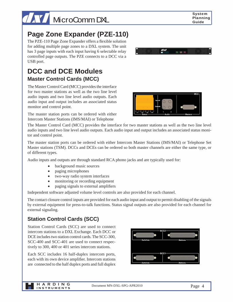
Page Zone Expander (PZE-110)The PZE-110 Page Zone Expander offers a fl exible solution for adding multiple page zones to a DXL system. The unit has 3 page inputs with each input having 6 selectable relay controlled page outputs. The PZE connects to a DCC via a USB port.
DCC and DCE ModulesMaster Control Cards (MCC)The Master Control Card (MCC) provides the interface for two master stations as well as the two line level audio inputs and two line level audio outputs. Each audio input and output includes an associated status monitor and control point.
The master station ports can be ordered with either Intercom Master Stations (IMS/MAI) or Telephone The Master Control Card (MCC) provides the interface for two master stations as well as the two line level audio inputs and two line level audio outputs. Each audio input and output includes an associated status moni-tor and control point.
The master station ports can be ordered with either Intercom Master Stations (IMS/MAI) or Telephone Set Master stations (TSM). DCCs and DCEs can be ordered so both master channels are either the same type, or of different types.
Audio inputs and outputs are through standard RCA phono jacks and are typically used for: background music sources paging microphones two-way radio system interfaces monitoring or recording equipment paging signals to external amplifi ers
Independent software adjusted volume level controls are also provided for each channel.
The contact closure control inputs are provided for each audio input and output to permit disabling of the signals by external equipment for press-to-talk functions. Status signal outputs are also provided for each channel for external signaling.
Station Control Cards (SCC)Station Control Cards (SCC) are used to connect intercom stations to a DXL Exchange. Each DCC or DCE includes two station control cards. The SCC-300, SCC-400 and SCC-401 are used to connect respec-tively to 300, 400 or 401 series intercom stations.
Each SCC includes 16 half-duplex intercom ports, each with its own device amplifi er. Intercom stations are connected to the half duplex ports and full duplex

MicroComm DXLSystemPlanningGuide
H A R D I N Gi n s t r u m e n t s
Document MN-DXL-SPG-APR2010 Page 5
Each SCC includes 16 half-duplex intercom ports, each with its own device amplifi er. Intercom stations are connected to the half duplex ports and full duplex handset stations are connected to two adjacent ports. Each intercom station must be connected to its own SCC port. Any attempt to parallel stations will upset the super-visory and audio networks.
Station Control Cards include all the circuitry to interface the intercom station switch contacts as well as sup-ply power to the station amplifi ers. A single twisted shielded pair cable is required to connect each 400 or 401 series intercom station to an SCC.
Two fi eld interface connectors are provided on each SCC-300, one for the audio channel and one for the switch connections. Separate fi eld interface cables for each function are also required. A twisted shielded pair cable is required to connect each station’s loudspeaker. A separate unshielded twisted pair cable is also required to connect each call switch. The SAB-300 also supports two switches per input with supervising resistors.
Process Control Cards (PCC)A Process Control Card (PCC) in each DCC and DCE controls the functions of each unit. They also provide the ports for system networking and control. The DCE card only requires the exchange network USB ports for communication with the DCC.
In addition to the USB ports, the DCCs also include: a 10/100BT Ethernet port for the system data network. two serial ports for setup, maintenance, host port and CCTV interfaces. an internal modem port for on-line system support from the factory or a remote service center. system audio trunk ports for either copper or fi ber optic networks.
DCCs and DCEs are equipped with an internal power supply that automatically adjusts to a variety of sources ranging from 100-240 VAC at 50 or 60 Hz. Maximum current draw is 2.75 amperes at 115 VAC and 2.0 amperes at 240 VAC. A NEMA 5-15 standard power cord is supplied with each unit.
Power Supplies
handset stations are connected to two adjacent ports. Station Control Cards (SCC) are used to connect intercom stations to a DXL Exchange. Each DCC or DCE includes two station control cards. The SCC-300, SCC-400 and SCC-401 are used to connect respectively to 300, 400 or 401 series intercom stations.

MicroComm DXLSystemPlanningGuide
H A R D I N Gi n s t r u m e n t s
Document MN-DXL-SPG-APR2010 Page 6
DXL Administrator SoftwareThe DXL Administrator Software operates on either a stand-alone desktop or laptop PC with a minimum confi guration consisting of a Windows XP Operating System, a Pentium processor, 256M of RAM and a 1G hard drive. This menu driven software package is used to defi ne the software confi guration of the system. It is also used for diagnostics, troubleshooting and upload-ing log information for viewing. The computer must be connected to any DCC in the system to download the software confi guration, or when either logging or diagnostic functions are being run, but need not be con-nected to the system at other times. Once a software confi guration is downloaded to a DCC it is distributed to the other DCC’s in the system through an Ethernet network.
The DXL Administrator computer can be connected to a DCC through either an RS-232 serial port or an Ethernet network port.
MicroComm DXLSystemPlanningGuide
H A R D I N Gi n s t r u m e n t s
Document MN-DXL-SPG-APR2010 Page 7
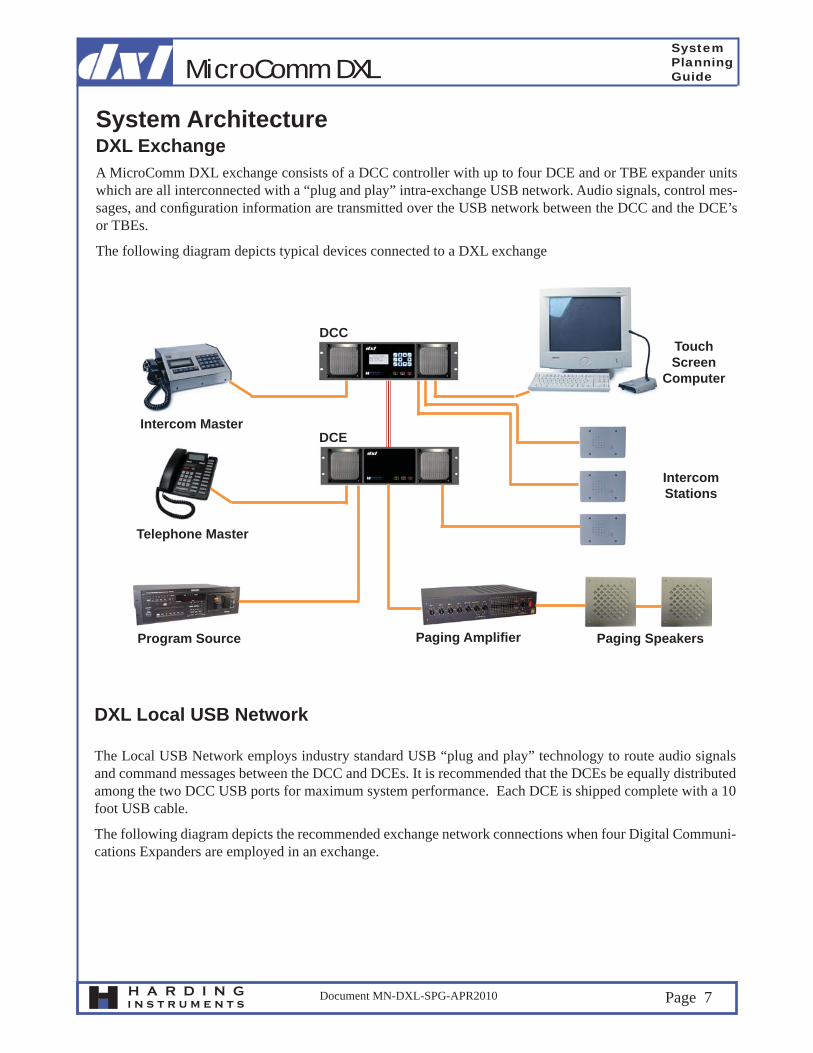
System ArchitectureDXL Exchange A MicroComm DXL exchange consists of a DCC controller with up to four DCE and or TBE expander units which are all interconnected with a “plug and play” intra-exchange USB network. Audio signals, control mes-sages, and confi guration information are transmitted over the USB network between the DCC and the DCE’s or TBEs.
The following diagram depicts typical devices connected to a DXL exchange
IntercomStations
TouchScreen
Computer
Paging SpeakersProgram Source Paging Amplifi er
Telephone Master
Intercom Master
DCC
DCE
DXL Local USB Network
The Local USB Network employs industry standard USB “plug and play” technology to route audio signals and command messages between the DCC and DCEs. It is recommended that the DCEs be equally distributed among the two DCC USB ports for maximum system performance. Each DCE is shipped complete with a 10 foot USB cable.
The following diagram depicts the recommended exchange network connections when four Digital Communi-cations Expanders are employed in an exchange.

MicroComm DXLSystemPlanningGuide
H A R D I N Gi n s t r u m e n t s
Document MN-DXL-SPG-APR2010 Page 8
DCC
DCEDCE
DCEDCE
Exchange USB Network Exchange USB Network
Exchange LonWorks Network
A DCC may have a card in its PCI slot that has a port to communicate to keypad/display master stations or discrete input/output modules over an Exchange LonWorks free topology data network. LonWorks is a widely used industry standard network that employs a single twisted pair cable wired in a free topology confi guration. That is, networks can be confi gured with a mix of serial and parallel connections. LonWorks cable specifi cations and listings are available on Echelon’s website at www.echelon.com.
The free topology network can extend up to 1300 feet in length. Network repeaters can extend that limit where required.
Discrete Input/Output (DIO) Modules are added to an exchange to provide a means to monitor switch inputs and outputs
All LonWorks devices in an exchange are connected to the DCC’s PCI card, even if the audio connections are made to DCE master ports.

MicroComm DXLSystemPlanningGuide
H A R D I N Gi n s t r u m e n t s
Document MN-DXL-SPG-APR2010 Page 9
FTR
DIO
DCC
DCE
DCE
IntercomMaster
IntercomMaster
IntercomMaster
MAIPanel MountMaster Station
Exchange LonWorks Network
Exchange LonWorks Network
Multiple DXL exchanges can be networked together to form a system capable of meeting the needs of larger facilities.
Up to 32 MicroComm DXL Exchange can be interconnected to form larger systems.
Digital audio trunks and data networks for signals, control messages, and status information are employed between exchanges to form larger systems. The digital audio trunk is connected to form a loop that includes all DCCs, while the data network employs standard Ethernet technology to connect the DCCs and any host port computers. Touch screen operator terminals and door control system PLCs are typical host port computer applications.
The following diagrams illustrates a system with multiple exchange.
DXL System with Multiple Exchanges

MicroComm DXLSystemPlanningGuide
H A R D I N Gi n s t r u m e n t s
Document MN-DXL-SPG-APR2010 Page 10
TouchScreen
Computer
TouchScreen
Computer
System Data Network (Ethernet)
System Audio Trunk Network
Exchange Data Network(LonWorks)
DXL ExchangeNetwork (USB)DXL Exchange
Network (USB)
DCC DCC DCC
DCE
DCEDCE
DCE
DCE
DIO
DIO
DCE

MicroComm DXLSystemPlanningGuide
H A R D I N Gi n s t r u m e n t s
Document MN-DXL-SPG-APR2010 Page 11
System Audio Trunk NetworkThe MicroComm DXL multi-channel System Audio Trunk consists of a single unidirectional loop that links all the DCC’s together. For the copper conductor option, the loop consists of one pair of 22 gage twisted cable and can span up to 8200 feet per segment. For the fi ber optic network option, the loop consists of one 62.5/125 m multimode fi bers and has a 10 dB power budget. For electrical isolation and lightning protection, the fi ber optic interface should be used.
Audio Trunk communication networks are unidirectional and must be looped around multiple points. When planning the Audio Trunk Network, ensure that all the DCC modules are ordered with the same format (cop-per or fi ber optic) interface.
Inter-Exchange NetworkEach DCC is equipped with a 10/100BT Ethernet port with RJ-45 jack for connection to the system data network and host port computers. The network itself may form a portion of a larger network that the system installer constructs with wiring and components he provides. The Inter-Exchange Network provides a link between the DCCs of each exchange and to host port computers. It employs standard Ethernet technology and may also be used to communicate with the Administration Software Computer. The design of the Ethernet network can be achieved with Ethernet switches or repeaters.
TouchScreen
Computer
TouchScreen
Computer
DCCDCCDCC
Ethernet Switch
DCC DCC DCC
one pair or one fi ber

MicroComm DXLSystemPlanningGuide
H A R D I N Gi n s t r u m e n t s
Document MN-DXL-SPG-APR2010 Page 12
Master Stations
Intercom Master Stations
Master Stations with full keypad/display functionality can be provided for desk top, fl ush panel mount, fl ush wall mount, or rack mount situations. While these units provide an operator with full control of a stand-alone system, they can also be used to supplement the operation of touch screen terminals and graphic control panels. Audio only masters can be used where all system functions are externally controlled. Telephone set master stations are employed where only administrative or basic functions are required.
The IMS-440 is a desktop standard size keyboard/display master station. The unit is compact, sturdy, and can be permanently fi xed to millwork if required. It provides an operator with audio communication, paging, and moni-toring functions as well as alarm and control functions. It also permits the operator to receive and place calls, put calls on hold, make public address and station group call announcements, and manage system background music operations. Other features include the ability to acknowledge, cancel, and reset incoming alarms and to monitor, activate and deactivate output points.
The IMS-640 is a telephone style keyboard/display intercom master station that uses Voice over Internet Protocol (VoIP). The IMS-640 connects to an exchange via the Inter-Exchange Network (an Ethernet network). The IMS-640 includes a 128x64 pixel graphical display and provides the operator with audio communications as well as alarm and control functions. It permits the operator to place calls, make public address and station group announcements and manage system background music operations. Other features include the ability to ac-knowledge, cancel, and reset incoming alarms and to monitor, activate and deactivate output points.

MicroComm DXLSystemPlanningGuide
H A R D I N Gi n s t r u m e n t s
Document MN-DXL-SPG-APR2010 Page 13
The IMS-130 is the panel mount, standard size display master station for use with the MAI-420 master audio interface. This unit is suitable for mounting directly into millwork, custom 19” rack mount panels, and other consoles. The IMS-130 in conjunction with the MAI-420 provides the operator with audio communication, paging, and monitoring as well as alarm and control functions. It also permits the operator to receive and place calls, put calls on hold, make public address and station group call announcements, and manage system background music operations. Other features include the ability to acknowledge, cancel, and reset incoming alarms and to monitor, activate and deactivate output points.
The MAI-420 Master Audio Interface provides audio communication circuitry and control between the DXL exchange and a remote location requiring a fl ush mount master station with an IMS-130 keypad/display module.
Connections are available for interfacing to a loud-speaker, microphone, telephone handset and hook switch, headset, external PTT switch, and phantom powered microphone.
The MAI-425 Master Audio Interface provides audio communication circuitry and control between the DXL exchange and a touch screen terminal or graphic control panel without keypad/display functionality.
Connections are available for interfacing to a loud-speaker, microphone, phantom powered microphone, external PTT switch, telephone handset and hook switch, and head set.
Graphic Control Master StationsThe TMM-640 Touchscreen Master Module is a small desktop unit for use with a touchscreen terminal. It is a Voice over Inter-net Protocol (VoIP) device that implements the industry standard Session Initiation Protocol (SIP).The unit consists of a speaker (c/w volume adjustment), an electret microphone, a push-to-talk (PTT) switch, and a LED status indicator. A front panel 2.5 mm jack also allows a variety of wired headsets to be utilized. The TMM-640 also provides contacts for an external PTT (foot) switch as well as a privacy handset, and also includes a 3.5 mm stereo output jack to provide line-level signalling for external amplifi ed speakers.

MicroComm DXLSystemPlanningGuide
H A R D I N Gi n s t r u m e n t s
Document MN-DXL-SPG-APR2010 Page 14
The DSM-140 Desktop Speaker Microphone is a com-pact unit for use with touch screen terminals. The unit consists of a push-to-talk (PTT) switch, speaker and an electret microphone that is either mounted on a 12 inch goose neck or fl ush mounted. The DSM-140 is connects to an MAI-420 or MAI-425.
Telephone Set Master StationsTelephone Set Master Stations provide administrative intercom functions through standard and cordless call display type telephone sets. Intercom communications, zone paging, listen-in monitoring, and output control are all available through telephone set masters. Function keys can be programmed for direct selection of commands and as speed dial numbers.

MicroComm DXLSystemPlanningGuide
H A R D I N Gi n s t r u m e n t s
Document MN-DXL-SPG-APR2010 Page 15
Intercom StationsIntercom stations are designed to mount on standard electrical device outlet boxes. They are offered with a variety of switch types and include handset and call cord options. Specialty intercom stations are also available for a variety of custom back boxes or for mounting on larger electrical boxes.
The ICM-420 and ICM-430 Intercom Stations are for use with the SCC-400 Station Control Cards. The intercom stations are suitable for use in high security areas and are designed for superb audio clarity in reverberant acoustic environments. The 400/401 series ICM’s incorporate an integral loudspeaker/microphone, and circuitry for transmission of all station audio, power, and up to two switch closures over a single shielded pair cable for reduced installation costs.
The ICM-421 and ICM-431 Intercom Stations contain a micro-controller to provide feedback information by means of an LED on the station (such as on-hold), and are used with the SCC-401 Station Control Cards. The intercom stations are suitable for use in high security areas and are designed for superb audio clarity in rever-berant acoustic environments. The ICM’s incorporate an integral loudspeaker/microphone, and circuitry for transmission of all station audio, power, up to two switch closures and LED control signals over a single shielded pair cable for reduced installation costs.
The ICS-4X0 and ICS-4X1 Intercom Specialty Stations are made for applications requiring replacement inter-coms for non-standard device boxes, unusual switch combinations, site specifi c engraving, etc. The ICS-4X0 intercom stations are for use with the SCC-400 Station Control Card. The ICS-4X1 intercom stations are for use with the SCC-401 Station Control Card. The intercom stations incorporate the same performance features of the standard intercom stations and can be ordered to meet the specifi c requirements of your facility.
400 and 401 Series Intercom Stations

MicroComm DXLSystemPlanningGuide
H A R D I N Gi n s t r u m e n t s
Document MN-DXL-SPG-APR2010 Page 16
The ICB-400 Intercom Boards are used to transform generic 45 ohm intercom stations to obtain full Micro-Comm quality and performance. They can also integrate ceiling speakers with 25-volt, 5-watt matching trans-formers and external call switch as intercom stations. Standard mounting holes with 2.51” spacing are used for mounting via nylon standoffs directly to station loudspeakers. Insulated versions with Velcro strips are used for overhead loudspeakers, parking gate pedestals and other similar applications.
300 Series and Generic Intercom Stations
Generic intercom stations are stations with a 25 volt, 1 watt speaker. In retroffi ting exising systems with this type of intercoms, a 300 Station Control Card (SCC) can be used to interface directly to the existing intercoms.
The ICM-320 and ICM-330 are 25 volt intercoms de-signed for customers who do not require the enhanced features and cross-talk protection provided by the 400 series intercom stations, or who wish to expand an exist-ing system that has generic intercoms. Generic 300 series intercom stations require a seperate pair of wires for the audio and up to two switch closures can be multiplexed over a second pair of wires.
MicroComm DXLSystemPlanningGuide
H A R D I N Gi n s t r u m e n t s
Document MN-DXL-SPG-APR2010 Page 17
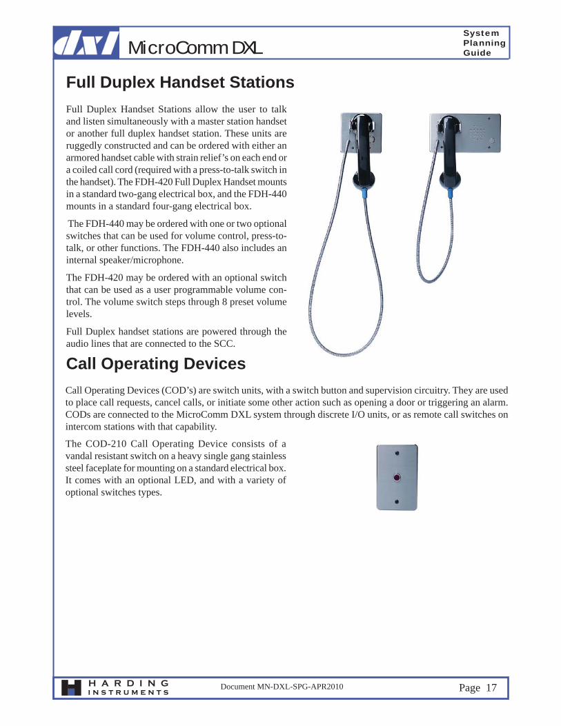
Full Duplex Handset StationsFull Duplex Handset Stations allow the user to talk and listen simultaneously with a master station handset or another full duplex handset station. These units are ruggedly constructed and can be ordered with either an armored handset cable with strain relief’s on each end or a coiled call cord (required with a press-to-talk switch in the handset). The FDH-420 Full Duplex Handset mounts in a standard two-gang electrical box, and the FDH-440 mounts in a standard four-gang electrical box.
The FDH-440 may be ordered with one or two optional switches that can be used for volume control, press-to-talk, or other functions. The FDH-440 also includes an internal speaker/microphone.
The FDH-420 may be ordered with an optional switch that can be used as a user programmable volume con-trol. The volume switch steps through 8 preset volume levels.
Full Duplex handset stations are powered through the audio lines that are connected to the SCC.
Call Operating DevicesCall Operating Devices (COD’s) are switch units, with a switch button and supervision circuitry. They are used to place call requests, cancel calls, or initiate some other action such as opening a door or triggering an alarm. CODs are connected to the MicroComm DXL system through discrete I/O units, or as remote call switches on intercom stations with that capability.
The COD-210 Call Operating Device consists of a vandal resistant switch on a heavy single gang stainless steel faceplate for mounting on a standard electrical box. It comes with an optional LED, and with a variety of optional switches types.
MicroComm DXLSystemPlanningGuide
H A R D I N Gi n s t r u m e n t s
Document MN-DXL-SPG-APR2010 Page 18
Discrete I/O ModulesDiscrete Input/Output (DIO) modules are used to monitor switch and contact closures and control auxiliary outputs. DIO modules require a local LonWorks Data Exchange network.
Inputs can be used for functions such as door position monitoring, panic alarms, building alarms, tone signal initiation, etc. They may also be used as a contact interface to an external control system to initiate externally controllable DXI functions.
Outputs are used to control external devices in response to input point activity or manual and automatic system commands. Typical control functions could include release of door locks solenoids, sounding of signaling de-vices, illuminating external indicating devices, etc.
MicroComm DIO modules are offered in two model series, each with different mounting options.
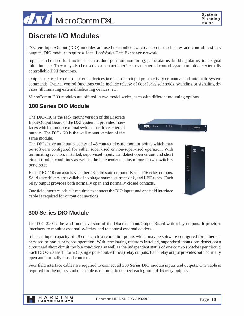
The DIO-110 is the rack mount version of the Discrete Input/Output Board of the DXI system. It provides inter-faces which monitor external switches or drive external outputs. The DIO-120 is the wall mount version of the same module.
100 Series DIO Module
The DIOs have an input capacity of 48 contact closure monitor points which may be software confi gured for either supervised or non-supervised operation. With terminating resistors installed, supervised inputs can detect open circuit and short circuit trouble conditions as well as the independent status of one or two switches per circuit.
Each DIO-110 can also have either 48 solid state output drivers or 16 relay outputs. Solid state drivers are available in voltage source, current sink, and LED types. Each relay output provides both normally open and normally closed contacts.
One fi eld interface cable is required to connect the DIO inputs and one fi eld interface cable is required for output connections.
300 Series DIO Module
The DIO-320 is the wall mount version of the Discrete Input/Output Board with relay outputs. It provides interfaces to monitor external switches and to control external devices.
It has an input capacity of 48 contact closure monitor points which may be software confi gured for either su-pervised or non-supervised operation. With terminating resistors installed, supervised inputs can detect open circuit and short circuit trouble conditions as well as the independent status of one or two switches per circuit.Each DIO-320 has 48 form C (single pole double throw) relay outputs. Each relay output provides both normally open and normally closed contacts.
Four fi eld interface cables are required to connect all 300 Series DIO module inputs and outputs. One cable is required for the inputs, and one cable is required to connect each group of 16 relay outputs.
MicroComm DXLSystemPlanningGuide
H A R D I N Gi n s t r u m e n t s
Document MN-DXL-SPG-APR2010 Page 19
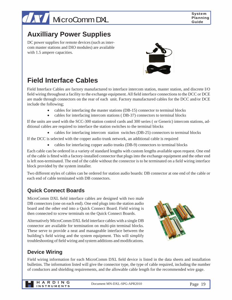
Quick Connect BoardsMicroComm DXL fi eld interface cables are designed with two male DB connectors (one on each end). One end plugs into the station audio board and the other end into a Quick Connect Board. Field wiring is then connected to screw terminals on the Quick Connect Boards.
Alternatively MicroComm DXL fi eld interface cables with a single DB connector are available for termination on multi-pin terminal blocks. These serve to provide a neat and manageable interface between the building’s fi eld wiring and the system equipment. This will simplify troubleshooting of fi eld wiring and system additions and modifi cations.
Field wiring information for each MicroComm DXL fi eld device is listed in the data sheets and installation bulletins. The information listed will give the connector type, the type of cable required, including the number of conductors and shielding requirements, and the allowable cable length for the recommended wire gage.
Field Interface CablesField Interface Cables are factory manufactured to interface intercom station, master station, and discrete I/O fi eld wiring throughout a facility to the exchange equipment. All fi eld interface connections to the DCC or DCE are made through connectors on the rear of each unit. Factory manufactured cables for the DCC and/or DCE include the following;
cables for interfacing the master stations (DB-15) connector to terminal blocks cables for interfacing intercom stations ( DB-37) connectors to terminal blocks
If the units are used with the SCC-300 station control cards and 300 series ( or Generic) intercom stations, ad-ditional cables are required to interface the station switches to the terminal blocks
cables for interfacing intercom station switches (DB-25) connectors to terminal blocksIf the DCC is selected with the copper audio trunk network, an additional cable is required
cables for interfacing copper audio trunks (DB-9) connectors to terminal blocksEach cable can be ordered in a variety of standard lengths with custom lengths available upon request. One end of the cable is fi tted with a factory-installed connector that plugs into the exchange equipment and the other end is left non-terminated. The end of the cable without the connector is to be terminated on a fi eld wiring interface block provided by the system installer.
Two different styles of cables can be ordered for station audio boards: DB connector at one end of the cable or each end of cable terminated with DB connectors.
Auxilliary Power SuppliesDC power supplies for remote devices (such as inter-com master stations and DIO modules) are available with 1.5 ampere capacities.
Device Wiring


![Anna Moshkivska [DXL MODELS]](https://img.dokumen.tips/doc/110x75/579076c11a28ab6874baa7fd/anna-moshkivska-dxl-models.jpg)