Embed Size (px)
Citation preview
Printed in Canada Copyright 2006-2011 Harding Instruments
MicroComm DXL
DXL Configuration Example
March 2011

DXL Configuration Example
Document DXL-APP-200-1.0 Page i
Table of Contents 1 PLANNING A PROJECT ................................................................................................................................................ 1
2 CREATING A BASIC CONFIGURATION FILE ........................................................................................................ 4
3 SETTING UP THE DXL SYSTEM............................................................................................................................... 28
4 UPLOADING APPLICATION AND CONFIGURATION FILES............................................................................ 29
5 INSTALL HEAD END EQUIPMENT USING THE “ADD/REMOVE” FRONT PANEL COMMANDS............ 32
6 APPENDIX 1: COMPOUND STATIONS THAT CALL IN AS THE COMPOUND STATION ID .................... 34
7 APPENDIX 2: SETTING FILTER PARAMETERS FOR 300-SERIES STATIONS............................................. 36

DXL Configuration Example
Document DXL-APP-200-1.0 Page 1
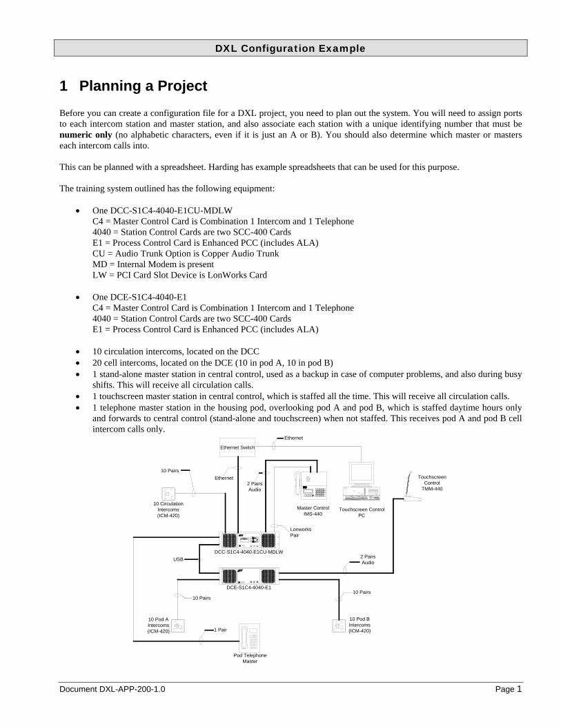
1 Planning a Project Before you can create a configuration file for a DXL project, you need to plan out the system. You will need to assign ports to each intercom station and master station, and also associate each station with a unique identifying number that must be numeric only (no alphabetic characters, even if it is just an A or B). You should also determine which master or masters each intercom calls into. This can be planned with a spreadsheet. Harding has example spreadsheets that can be used for this purpose. The training system outlined has the following equipment:
One DCC-S1C4-4040-E1CU-MDLW C4 = Master Control Card is Combination 1 Intercom and 1 Telephone 4040 = Station Control Cards are two SCC-400 Cards E1 = Process Control Card is Enhanced PCC (includes ALA) CU = Audio Trunk Option is Copper Audio Trunk MD = Internal Modem is present LW = PCI Card Slot Device is LonWorks Card
One DCE-S1C4-4040-E1
C4 = Master Control Card is Combination 1 Intercom and 1 Telephone 4040 = Station Control Cards are two SCC-400 Cards E1 = Process Control Card is Enhanced PCC (includes ALA)
10 circulation intercoms, located on the DCC 20 cell intercoms, located on the DCE (10 in pod A, 10 in pod B) 1 stand-alone master station in central control, used as a backup in case of computer problems, and also during busy
shifts. This will receive all circulation calls. 1 touchscreen master station in central control, which is staffed all the time. This will receive all circulation calls. 1 telephone master station in the housing pod, overlooking pod A and pod B, which is staffed daytime hours only
and forwards to central control (stand-alone and touchscreen) when not staffed. This receives pod A and pod B cell intercom calls only.
FaultRun Install
InstallRun Fault
3
9
6
#
CLEAR
ENTER
54
*
7
0
8
1 2
PTT
MIC
HEAD
10 Circulation Intercoms(ICM-420)
10 Pod A Intercoms(ICM-420)
10 Pod B Intercoms(ICM-420)
DCC-S1C4-4040-E1CU-MDLW
DCE-S1C4-4040-E1
Master Control IMS-440
USB
Touchscreen Control
TMM-440
Pod Telephone Master
Ethernet Switch
Touchscreen Control PC
10 Pairs10 Pairs
2 PairsAudio
LonworksPair
2 PairsAudio
10 Pairs
1 Pair
Ethernet
Ethernet

DXL Configuration Example
Page 2 March 2011 Document DXL-APP-200-1.0
For this training configuration, the following spreadsheets were created: Head end equipment
EXCHANGE: 1 Main Exchange IP address 10.0.0.95
LOCATION: Demo Room
DCC Information PCC type Audio Trunk PCI Card Modem
PCC Type ALA Copper Xlon Yes MCC Type IMS/TSM SCC1 Type 400
SCC2 Type 400 DCE1
Information PCC type
PCC Type ALA MCC Type IMS/TSM SCC1 Type 400
SCC2 Type 400 Master stations:
MASTER STATIONS MASTER
ID MASTER
NAME EXCH BOX PORT 2NDARYMST
CALL LISTSTATION CALL
LIST ZONE CALL
LIST
1 Master Control 1 DCC 1 N/A All
2 Touchscreen
Control 1 DCE1 1 N/A All
3 Telephone
Master 1 DCC 1 (Telephone) 10 201-210,301-310
Master groups:
MASTER GROUPS
GROUP ID GROUP NAME MASTERS IN GROUP SECONDARY
10 Central 1-2 0

DXL Configuration Example
Document DXL-APP-200-1.0 Page 3
Intercom stations:
Exchange 1 Box DCC SCC 1
LOCATION: Demo Room
Port STATION ID NO. STATION NAME MASTER LOCATION
1 101 Door IC101 10 2 102 Door IC102 10 3 103 Door IC103 10 4 104 Door IC104 10 5 105 Door IC105 10 6 106 Door IC106 10 7 107 Door IC107 10 8 108 Door IC108 10 9 109 Door IC109 10
10 110 Door IC110 10 11 12 13 14 15
16
Exchange 1 Box DCE1 SCC 1
LOCATION: Demo Room
Port STATION ID NO. STATION NAME MASTER LOCATION
1 201 Cell A201 3 2 202 Cell A202 3 3 203 Cell A203 3 4 204 Cell A204 3 5 205 Cell A205 3 6 206 Cell A206 3 7 207 Cell A207 3 8 208 Cell A208 3 9 209 Cell A209 3
10 210 Cell A210 3 11 301 Cell B301 3 12 302 Cell B302 3 13 303 Cell B303 3 14 304 Cell B304 3 15 305 Cell B305 3
16 306 Cell B306 3
DXL Configuration Example
Page 4 March 2011 Document DXL-APP-200-1.0
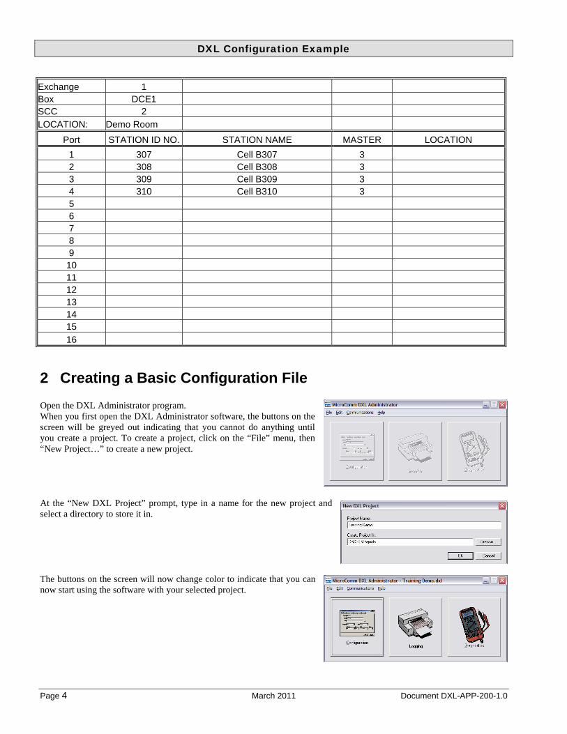
Exchange 1 Box DCE1 SCC 2
LOCATION: Demo Room
Port STATION ID NO. STATION NAME MASTER LOCATION
1 307 Cell B307 3 2 308 Cell B308 3 3 309 Cell B309 3 4 310 Cell B310 3 5 6 7 8 9
10 11 12 13 14 15
16
2 Creating a Basic Configuration File Open the DXL Administrator program. When you first open the DXL Administrator software, the buttons on the screen will be greyed out indicating that you cannot do anything until you create a project. To create a project, click on the “File” menu, then “New Project…” to create a new project. At the “New DXL Project” prompt, type in a name for the new project and select a directory to store it in. The buttons on the screen will now change color to indicate that you can now start using the software with your selected project.

DXL Configuration Example
Document DXL-APP-200-1.0 Page 5
Click Configuration to create a new configuration file, and name this configuration. If you add some new intercoms later you will need to save a new configuration, so it is recommended to put a version number as part of the configuration name. Once you have made a configuration, you will be in the configuration editor main screen. The title bar will indicate the name of the configuration being worked on.
The configuration editor is divided into four main parts.
The top of the screen contains the menu bars, and the “Configure:” selection box (which indicates what part of the intercom system you are going to configure).
The bottom part of the screen contains any context specific action buttons (such as adding, or deleting portions of the system).
The left pane shows the overall tree view of the components specified in the “Configure:” box. The “View:” box allows you to select a view (I.E. choose how you want to see the tree ordered) – the choices for view will change depending on what type of components you are currently modifying. This is an outline view, you can click on items with “+” to the left to expand the view (see what is within that component), and you can click on items with “-” to the left to compress the view (to hide the contents of those components).
The right pane shows the selected components and allows you to select or modify them. To modify any parameter in the right pane, either double-click on it or click it to select it then click on “Properties…” at the bottom of the screen.
You will create the system by selecting an item in the “Configure:” box, create those types of items, then select the next item in the “Configure:” box and create those until you have created the system. For the most part, you start at the top “Configure:” item and work your way down the list, creating any items that are relevant to your system.
Selecting Configure: gives you the options shown to the right

DXL Configuration Example
Page 6 March 2011 Document DXL-APP-200-1.0
The first thing to do is allow editing of this new configuration. If configuration is locked (the lock icon beside the Lock/Unlock button on top is closed) press the “Unlock” button to unlock the configuration (which will change the lock icon to open and the button text to “Lock”). When you create a configuration, it will automatically be unlocked. However, if you are modifying an existing configuration, with the default settings it will start in the locked state and you must unlock it first.
Once you have created a configuration, you can use the “Edit” menu to change general settings.
Selecting “Preferences…” will allow you to set overall DXL Administrator preferences, such as whether the configuration should be locked or unlocked on start-up. One useful setting is on the “Configuration” tab. You can check mark the “On open, automatically unlock non-activated and non-password protected configurations for editing” box so that the configuration will always start unlocked, ready for editing.

DXL Configuration Example
Document DXL-APP-200-1.0 Page 7
Also on this menu, you can select “Sounds…” to customize the sounds played by the intercom system for various events. This example will add call announce tones to the system. These are chimes that can sound before, during, and after a call indicating that the intercom is now being spoken to and monitored. Also used in this example will be call request acknowledge tones to the system. These are tones that can be played on the station speakers when the call request button on the station has been pushed, giving the person waiting at the station confirmation that their button press has been acknowledged by the system. Custom sounds can be imported to the system for these tones, or the default system tones can be used. To view the current sounds or import new sounds into the system you can select “Edit-> Sounds…” from the main menus. The left pane shows the sounds in the DXL administrator directory and the right pane shows the sounds that have been imported or copied to the project configuration directory. Standard sounds in Windows “WAV” format can be imported to either the administrator directory or configuration directory using the appropriate “Import…” button, or if you have a microphone on your PC, you can record sounds directly from the microphone using the associated “Record…” button. This example will use one of the predefined tones. The “1000Hz-250ms” tone will be used for the call pre-announce tone, and the“500Hz-250ms” tone will be used for the call request acknowledge tone. Since they are already listed in the Shared Sounds pane, this window is not needed. Click the “Close” button in the top right to close this window. For the rest of the configuration, use the main screens and “Configure:” selections, going through the selections from top to bottom in two passes. This first pass will add mostly the head end equipment hardware and then the other devices (masters, stations, page zones, etc) to the system. A second pass through the configuration will fill out more information including call routing, permissions, and other detailed information. The first step in the configuration is to create exchanges. To create a new exchange, make sure the “Configure:” box has “Hardware” selected. Then click the “Add Exchange…” button at the bottom of the screen. Each exchange needs to be named and given a unique TCP/IP network address for the DCC that controls the exchange. The network administrator for this project should assign an IP address for each Exchange in the system. In this example the address “10.0.0.95” was assigned to this exchange.

DXL Configuration Example
Page 8 March 2011 Document DXL-APP-200-1.0
Now the configuration editor will show the new exchange in the system.
Select your new exchange on the left pane (“Main Exchange”). The bottom of the screen will change to show what actions can be performed. In this case you want to add a DCC controller by clicking on “Add DCC…” Select the options that reflect the equipment you are adding (see the above).
The screen shown to the right reflects the new controller added, and since this exchange now has a controller, there are more options to add extra components including adding a DCE expander.

DXL Configuration Example
Document DXL-APP-200-1.0 Page 9
To add the expander, click “Add DCE…” then select the appropriate options.
You have now configured all of the required head end hardware in the system. The screen to the right shows the view with the DCC and DCE items expanded (by clicking the + signs next to them in the left pane). The next item in the “Configure:” box is “Exchanges”, but this information has already been entered above.
DXL Configuration Example
Page 10 March 2011 Document DXL-APP-200-1.0
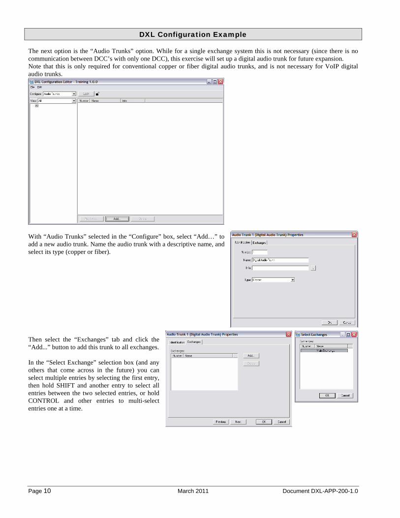
The next option is the “Audio Trunks” option. While for a single exchange system this is not necessary (since there is no communication between DCC’s with only one DCC), this exercise will set up a digital audio trunk for future expansion. Note that this is only required for conventional copper or fiber digital audio trunks, and is not necessary for VoIP digital audio trunks.
With “Audio Trunks” selected in the “Configure” box, select “Add…” to add a new audio trunk. Name the audio trunk with a descriptive name, and select its type (copper or fiber).
Then select the “Exchanges” tab and click the “Add...” button to add this trunk to all exchanges. In the “Select Exchange” selection box (and any others that come across in the future) you can select multiple entries by selecting the first entry, then hold SHIFT and another entry to select all entries between the two selected entries, or hold CONTROL and other entries to multi-select entries one at a time.

DXL Configuration Example
Document DXL-APP-200-1.0 Page 11
After adding the exchange the “Exchanges” tab will reflect the exchanges that will be connected in this digital audio trunk loop. Click “OK” to return to the digital audio trunk selection window. The digital audio trunks are now configured. Now the master hardware can be configured. In the “Configure:” box, select “Masters”.
In this project, The DCC will have one stand-alone master on the master port, and one telephone master on the telephone port. The DCE will have one touchscreen master on the master port. The stand-alone master will be numbered “1”, touchscreen master numbered “2”, and telephone master numbered “3”. Click on “Add…” at the bottom of the screen to add a master. On the “Identification” tab type in the name and select what type of master it is. The information about what Exchange, Box, Card, and Port will change and the system will find the first free port of that type available. If you want to specify a specific port for this master you can change any of these parameters at this time. In this case, the port is on the Main Exchange DCC IMS/TSM MCC port 1, just as the default set up. Click OK to go back to the master selection window.

DXL Configuration Example
Page 12 March 2011 Document DXL-APP-200-1.0
Now add master 2, a TMM (Touchscreen Master Module) master. Next, add Master 3 for the telephone set master. However, clicking “Add…” brings up a warning: This warning came up because by default, the system tries to allocate another master of the same type you last selected (in this case, a TMM master) for the new master. However, in this system there are only two IMS/TMM master ports in the system (one on the DCC, and one on the DCE) and both are already used. However the master about to be added is a telephone set master (TSM) and there are still two telephone ports free, so just click on OK to continue. The Master 3 Properties screen shows that the master type is a TMM, (the last type that was added) but the Exchange, Box, Card, and Port are blank (because there are no available TMM ports). Change the “Type” to “TSM” (Telephone Set Master) and now the system checks for the first available TSM port. The Main Exchange DCC IMS/TSM MCC Port 1 is the port that is desired to put the telephone on so enter the name, then click the “OK” button.

DXL Configuration Example
Document DXL-APP-200-1.0 Page 13
Finally, this example will add a “Master Group”. A master group allows intercom stations to call into multiple masters, and this “group” is how these masters are specified. In this case, a master group (arbitrarily numbered 10 in this example) will group together the central control masters 1 and 2 so that circulation intercoms will call into both masters. Add a new master, name it, and define its type as “Master Group”. Select the “Members” tab, then “Add…” to add masters to this group, then click master 1 and hold shift and click master 2 to add masters 1 to 2. Click OK to go back to the master group properties.
Click “OK” to go back to the master configuration window.

DXL Configuration Example
Page 14 March 2011 Document DXL-APP-200-1.0
This step will initially configure the “types” of stations that are required. These are set up with “Station Templates”. This allows the general parameters for the types of stations to be easily modified, such that if any changes are required later on for a particular type of station or stations, changing the template will change any stations using that template. While station templates are not required, they make creating and modifying the configuration easier and more logical for the installer and maintenance staff. It is generally most convenient to set up separate templates for the following circumstances
Different station types should be set up as separate templates (I.E. full duplex stations should have different templates than half duplex stations)
Different station functionality should be given different templates (I.E. cell intercoms with music buttons should be separate from circulation intercoms)
Stations calling different masters can be given different templates. (I.E. intercoms in pod A which calls master A would be set up under a template for pod A stations, while stations for pod B can be given a template for pod B stations).
In this example, configure a station template for circulation intercoms, and two templates for intercoms in Pod A and Pod B. Select “Station Templates” in the “Configure:” box. Click the “Add…” button to add a new template. Starting on the “Identification” tab, enter the following: The check box for “Compound Member” allows two or more intercoms to be grouped together for a double-sided door (so that the intercoms on the inside and outside of the door can be logically grouped together and called so that the master can talk/listen to both intercoms at once when it is so called). This is mostly used for circulation intercoms, so the circulation intercom template here will check this option. The information on the other tabs will be configured later on in this example. Click “OK” to return to the station template screen. Now create two more templates for Pod A and Pod B stations. These will be similar to the above, but without the “Compound Member” selected.
DXL Configuration Example
Document DXL-APP-200-1.0 Page 15
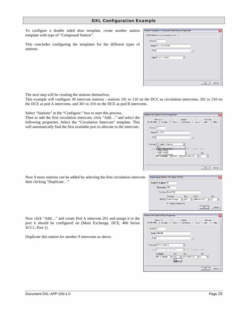
To configure a double sided door template, create another station template with type of “Compound Station”. This concludes configuring the templates for the different types of stations. The next step will be creating the stations themselves. This example will configure 30 intercom stations - stations 101 to 110 on the DCC as circulation intercoms, 201 to 210 on the DCE as pod A intercoms, and 301 to 310 on the DCE as pod B intercoms. Select “Stations” in the “Configure:” box to start this process. Then to add the first circulation intercom, click “Add…” and select the following properties. Select the “Circulation Intercom” template. This will automatically find the first available port to allocate to the intercom. Now 9 more stations can be added by selecting the first circulation intercom then clicking “Duplicate…” Now click “Add…” and create Pod A intercom 201 and assign it to the port it should be configured on (Main Exchange, DCE, 400 Series SCC1, Port 1). Duplicate this station for another 9 intercoms as above.
DXL Configuration Example
Page 16 March 2011 Document DXL-APP-200-1.0
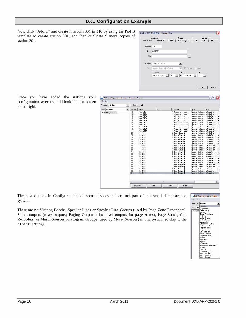
Now click “Add…” and create intercom 301 to 310 by using the Pod B template to create station 301, and then duplicate 9 more copies of station 301. Once you have added the stations your configuration screen should look like the screen to the right. The next options in Configure: include some devices that are not part of this small demonstration system. There are no Visiting Booths, Speaker Lines or Speaker Line Groups (used by Page Zone Expanders), Status outputs (relay outputs) Paging Outputs (line level outputs for page zones), Page Zones, Call Recorders, or Music Sources or Program Groups (used by Music Sources) in this system, so skip to the “Tones” settings.

DXL Configuration Example
Document DXL-APP-200-1.0 Page 17
To define a tone for an announce tone, select “Tones” from the “Configure:” box, and click the “Add…” button to add a tone. Click on the “Select…” button to select which sound to use for this tone. You can select sounds in the DXL Administrator directory (Shared Sounds) or sounds in the configuration directory (Configuration Sounds). This example will use a standard tone included with the DXL Administrator. Since the tone desired is in the “Shared Sounds” pane, click “Shared Sounds” and the list of sounds will come up. For this example, select the “1000Hz-250ms” sound. You can preview the sound on your PC speakers by clicking “Play”. When you have the sound you like click “OK”.
The “Settings” tab of the tone configuration allows you to change some other parameters such as the tone’s overall volume, and repeat rate. A call announce tone doesn’t normally need to change any of the default settings on this page. To define a tone for a call request acknowledge, click the “Add…” button to add a tone. Then click “Select” to select the tone.

DXL Configuration Example
Page 18 March 2011 Document DXL-APP-200-1.0
On the “Select Tone Sound” window, click “Shared Sounds” and select the “500Hz-250ms” sound. Click “OK” to accept this tone. For a call request acknowledge tone, some of the other settings on the may be used. Most commonly used is the “Periodic” check box and the “Period (sec)” value. On the default setting (“Periodic” is not checked) for a call request acknowledge tone, the speaker will play a tone only once when pressed and will not play again until the call is answered (typically by a master station). If “Periodic” is checked, there will be a periodic tone played in addition to the initial tone. The speaker will play the tone when the button is first pressed, and also play the tone at “Period (sec)” second intervals afterward, until the call is answered. For this example, check the “Periodic” setting and set the “Period (sec)” interval to 15 seconds. Once the tones are defined the tones screen will look like the following:

DXL Configuration Example
Document DXL-APP-200-1.0 Page 19
The next item that is relevant to this configuration is the “System” settings. It contains settings relevant to overall system operation, including telephone set operation, master operation, and other general parameters. Select “System” from the “Configure:” box. A new window will pop up. The settings on the “TSM Dialing” tab will affect how a TSM (Telephone Set Master) dials the “phone number” of an intercom station. When using a telephone master to call an intercom station, master, page zone, or other device, you need to enter a prefix digit (0 for master, # for station, * for page zone) and then enter a fixed digit number to dial the master, station, or page zone needed. You need to specify how many digits are in the dial number. In this example, intercom station numbers are three digits (intercoms are numbered 101-110, 201-210, and 301-310), hence the Id digits need to be set to 3. Under “Fixed Length Id Digits”, change the values for “Station” and “Station Group” to 3. To be consistent, set the other settings under this heading to 3 as well (so masters, page zones, etc. will need 3 digits to dial to them). On the “Master Operations” tab are some settings relevant to masters. Checkmark the “Disable Host command permission checks” box. What this does is sets the system up so that all commands sent from a host (PLC, Touchscreen PC, server, etc.) will bypass permission checks by the DXL system. If this is not check marked, you need to explicitly set the permissions for each master to indicate what the master (host controlled or not) is allowed to do. If this setting is not check marked, your programmer will have to add the permissions to the DXL configuration for any new functions or stations that the host controls, otherwise the commands will fail without permission. The next step will be to define how the host (PLC, Touchscreen, or server) communicates with the system. This example only shows the basic settings to create a host but does not show all of the full interfacing settings. A full example on how to program the host port is in another document which will show these settings and more. This example will set up a Modbus TCP/IP PLC type interface. Select “Host Ports” in the “Configure:” box and click “Add…” Give the host interface a name.

DXL Configuration Example
Page 20 March 2011 Document DXL-APP-200-1.0
Go to the “Connection” tab, and for “Exchange”, select Exchange 1, then select “Ethernet”, then select the TCP/IP port number that your touchscreen interface/PLC/server will use. Most Modbus PLC’s and touchscreen software will use port 502, so change the port number to 502 above. This will generate the following warning, which you can ignore since Modbus is a well known service.
The options on the “Protocol” tab further define the Modbus protocol parameters. Select the “Register Based Messages” box and select the “Modbus/TCP” PLC Protocol. For this example, use “4 digit” register addresses. For Modbus this means that the register will start with 4 (for “holding” registers) and have 4 digits after that, for register addresses of 40000 to 49999. To do this, set the “Digits” value under “Normal Register Addr” and “Ext. Register Address” to 4. On the “Masters” tab, select which masters are controlled by this host port. In this example, only the “Touchscreen Control” master will be selected. To select the communications mode, select the “Registers” tab. This example will use “Polled” mode.

DXL Configuration Example
Document DXL-APP-200-1.0 Page 21
To select which Modbus registers the touchscreen control master will use, go back to the “Masters” tab, then select the “Touchscreen Control” master, click the “Edit Master Registers…” button, and enter the following: Command: 40001 Status: 40027 Alarm Queue: 40011 Click “OK” to exit this window. then “OK” to exit the Host Port window.
The first pass (creating all the necessary hardware) is now complete. Now the system call routing and permissions can be defined. Start again at the top of the “Configure:” items list. Since “Hardware”, “Exchange”, and “Audio Trunk” settings are all fully entered, start by selecting “Masters” from the “Configure:” box. Select the “Master Control” master. You can now change the parameters in the other tabs, although most do not need changing for this example. On the “Switches” page the “Report Faults to Master” can be changed to “Touchscreen Control”. This is optional, but when used, this sends a message to the touchscreen if the stand-alone master has any wiring problems. If this is used, the host programming can detect if there is a master wiring fault and can be programmed to indicate an alarm for this fault.

DXL Configuration Example
Page 22 March 2011 Document DXL-APP-200-1.0
On the “Tones” tab, the call announce tone start and end for the master can be set to the newly created tone named “Call Announce”. The “Levels” tab allows adjustment of the speaker (intercom to master) and microphone (master to intercom) sensitivity levels, as well as the buzzer volume on the master. The “Use AGC” button, if selected, allows the DXL system to automatically adjust the microphone volume for quieter or louder staff members so that the person at the intercom station will hear roughly the same volume level whether there is a loud or quiet staff member in the control room. In this example the only change is the “Initial Buzzer Volume” which can be dragged to the medium volume setting, setting 3 (or 3 typed into the appropriate box). For masters with keypads (stand-alone and telephone masters) you will want to go to the “Permissions” tab and allow the masters to call the intercom stations (and other devices) in their area. The most common permission that is given to masters is the ability to call stations. Select the “Call Station” function, and then add stations to the list of stations that can be called from that master. If other functions (such as calling masters or page zones, enabling music, disabling call buttons, etc.) are desired from this master, select the appropriate function and add the list of stations/devices to the list. For Master 1 in this example, click the “Add…” button. Add all of the intercoms to the “Call Station” function for this master. Click the first intercom, then scroll down to the last intercom and shift-click to select all of them, and then click OK.

DXL Configuration Example
Document DXL-APP-200-1.0 Page 23
The screen will now show all of the intercoms that this master is allowed to call.
Repeat the above settings for the Touchscreen Control master (Master 2), except that there is no “Initial Buzzer” value in the Levels tab, and you do not have to change any permissions in the “Permissions” tab since in the System properties you have set “Disable Host command permission checks”. For the Telephone master, some more advanced features will be used. The telephone, in this case, will be the first place where calls from the pods will be sent. In addition to this, for this example, if the cells calls are not answered by the telephone within one minute, they will be forwarded to the touchscreen and stand-alone master. Also, the telephone will not be allowed to call circulation intercoms, only the intercoms within the pod. First, modify the Telephone Master (master 3). Telephones have no switches so there is nothing on the “Switches” tab to adjust. Add the call announce start and end tone on the “Tones” tab as above. To set the above forwarding feature, select the “Secondary” tab. Set the “Secondary Master” setting to the Central Control group defined earlier – Selecting this master group will forward unanswered calls to both the Master Control master and Touchscreen Control Master. Check mark the “Enable Secondary Alarm Timeout” box and enter a time out value (in seconds). This example will use one minute (60 seconds). The desired operation for this master is to be able to dial up only the pod A and pod B intercoms. Go to the “Permissions” tab, “Call Station” function, and add stations, using the multi-select function to add all of the A and B pod cells. The configuration for masters is now complete.

DXL Configuration Example
Page 24 March 2011 Document DXL-APP-200-1.0
The next step is configuring the stations. In this example, station templates are defined for the different type and grouping of stations. In doing this, all of the settings can be changed simply by changing the templates. In the “Configure” box, select “Station Templates”. Edit the “Circulation Intercom” template. The “Identification” tab was previously set up. Go to the “Switches” tab to set up the call buttons. The switches on intercoms are numbered “1” (top) and “2” (bottom). One button Harding Instruments intercom stations have only the bottom button, so to define that button as a call button, double-click on switch “2”.
2 Button Intercom 1 Button Intercom
On the Switch Properties screen, select the function “Call Request” and select the master group 10 (Central Control) so that all the stations using this template will call into both the Master Control master and Touchscreen Control master. Note that you may get a warning when you change the switch, indicating that all stations that use that template will be changed.
After changing the switch properties, click OK to go to the main page. To inform the masters when there are any faults with the intercoms select the Central Control master in the “Report Faults to Master” selection box. This is optional but will display faults on IMS masters and send messages indicating station faults to the host which can be programmed in the host to alarm if there are any stations that have faulted.
Switch A/Switch 1
Switch B/Switch 2 Switch B/Switch 2

DXL Configuration Example
Document DXL-APP-200-1.0 Page 25
To have call announce tones, select the “Tones” tab and under the “Call Announce” heading, set the “Start” and “End” tones to the “Call Announce” tone previously defined. Also under the heading, to have a call request acknowledge tone when the call request button is pushed, set the “Tone” setting under the “Call Request Acknowledge” heading to the “Call Acknowledge” tone previously defined. For the Pod A and Pod B intercoms, the process is similar. For this example, pod intercoms will be slightly different than circulation intercoms. Pod intercoms call into the telephone master rather than central control. Also, to make connections silent so that staff can listen in to cells without audible warning, these stations will not have a Call Announce start or end tone. First make changes to the “Pod A Station” template. On the “Switches” tab, Double-click switch 2 to go to the Switch Properties page. Set the “Function” to “Call Request”. Then select the “Telephone Master” as the master the call requests will be sent to. Since telephone masters cannot indicate faults, on the main “Switches” tab, leave the “Report Faults To Master” set to the Central Control master. On the “Tones” tab, leave the “Call Announce” Start and End tones as “None”. If you want the call request button to play the tone, you can set the “Tone” setting under “Call Request Acknowledge” to the “Call Request Acknowledge” tone, or you can leave it at “None”. Repeat the above settings for the Pod B Station Also you should also change the tones settings for the Double-Sided Door template so that it will have call announce start and end tones and call request acknowledge tones.

DXL Configuration Example
Page 26 March 2011 Document DXL-APP-200-1.0
Now all intercom templates have been set up. Because the intercoms use the templates, all the intercoms are also now all set up. If at some later time in the future, separate masters are added for Pod A and Pod B (as opposed to a telephone master answering both pods) you simply need to change the template for the pod’s stations and all stations will automatically change to reflect the template they were based on. This example also makes the use of a “compound station” for a double-sided door, such as a pair of sally port intercoms. In this case, door intercoms 109 and 110 are intercoms on two sides of the same door. While they can be addressed individually, the specifier also requested that these intercoms can be called as a unit so that staff can talk to the person going through the door until the call is ended. A grouping of two to four stations in this method on the DXL is called a “Compound station”. The individual stations that are allowed to do this must have the “Compound station” box checked in the “Identification” tab of the station or station template properties window. In this case all of the circulation intercoms are capable of being compound stations because the template has the “Compound Member” check box checked. To add this compound station, add a new station, and select the “Double Sided Door” template defined earlier, and give the station a name and number. To select which stations are parts of this group, select the “Members” tab, and then click the “Add…” button to add stations 109 and 110 into the list. If you need the IMS master to call this, you need to add this to the master’s permission lists, or add the master to the station’s permission lists. To do this from the station, go to the “Permissions” tab, then select function “Call Station”. Click “Add” to add which masters are allowed to call this compound station. In this case, Master 1.

DXL Configuration Example
Document DXL-APP-200-1.0 Page 27
Now, if the staff member wants to talk to both sides of that door, they can call this station (181) and they will listen to both station 109 and 110 when listening, and talk to 109 and 110 when talking. However, the call button for stations 109 and 110 will still call in individually with the single station. If you wish to change this so that the call button will always call in as the grouped station, then you will need to create another template for the intercoms that will be part of the compound stations, and in those stations, change the station template to your new compound station template, and in that template change the switch action to “Compound Call Request”. This is shown in the appendix of this example. This completes the basic configuration of the DXL system. Save the configuration using the “File->Save” menu.

DXL Configuration Example
Page 28 March 2011 Document DXL-APP-200-1.0
3 Setting up the DXL System First the DXL DCC’s in the system must be set up with Ethernet address that matches the configuration created for them. In this case one DCC is in the system and it is IP address 10.0.0.95. You need to power up the DCC’s, and hook them up to an Ethernet hub or switch along with the PC you made the configuration with. The PC must be within the same Ethernet subnet (I.E. the first part of the Ethernet address must be the same as what is on the DXL system). Your network administrator will be able to tell you how to set up your PC so that it is on the same subnet as the DXL system. Once the DCC is powered up and hooked into the network you can use the front panel on the DCC to adjust its Ethernet address. Press the “Setup” button on the DCC keyboard. Then use the cursor down button to select “Ethernet IP/Mask” and press the “Enter/Ack” button. The cursor should be on the IP address setting. Use the cursor right button to select a digit in the address to adjust and use the up or down arrows to change the address to 010.000.000.095 and then press the “Enter/Ack” button to enter the address. If your network administrator has assigned a different subnet other than 255.255.255.000 then you can use the down arrow to select that then use the right arrow and up/down arrows to adjust these parameters as well. Press the “Prev” button to return to the main menus. The system will then prompt to reboot. Press “Enter/Ack” to reboot with the new address.
DXL Configuration Example
Document DXL-APP-200-1.0 Page 29
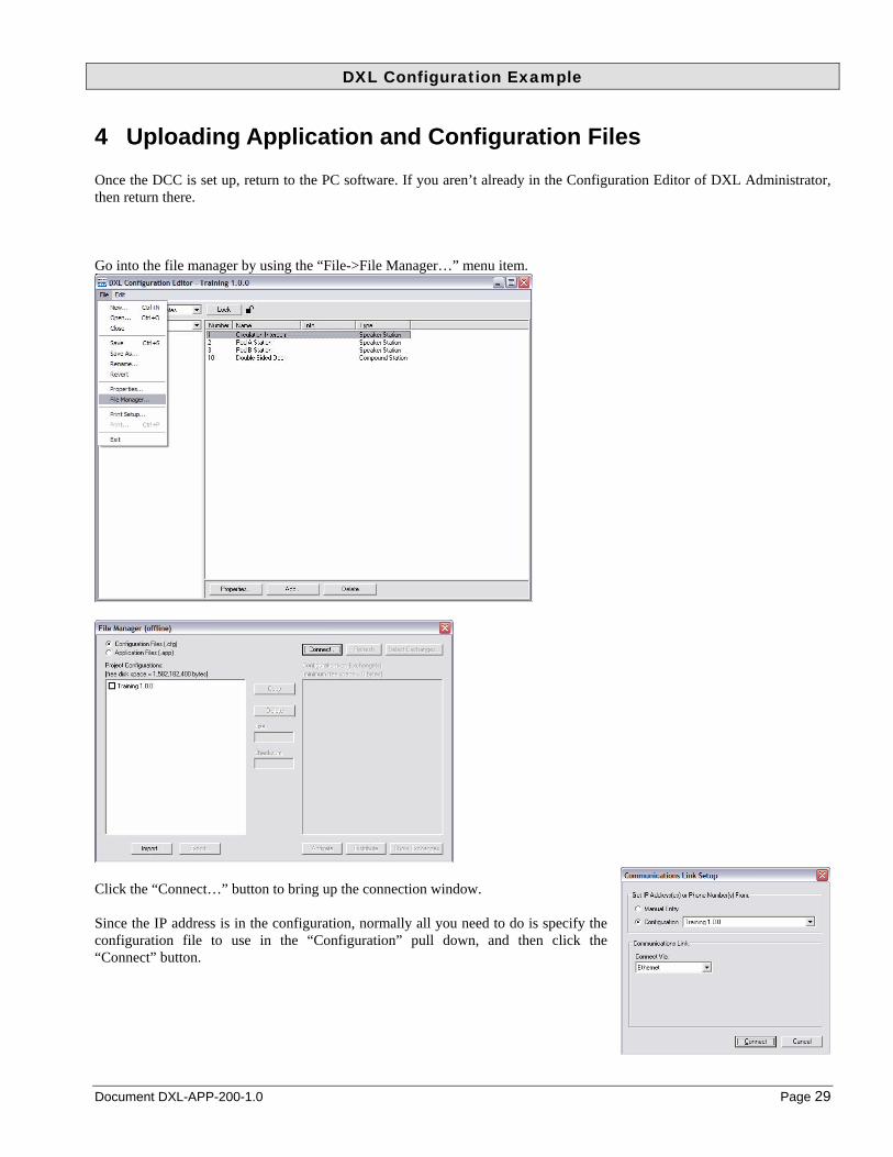
4 Uploading Application and Configuration Files Once the DCC is set up, return to the PC software. If you aren’t already in the Configuration Editor of DXL Administrator, then return there. Go into the file manager by using the “File->File Manager…” menu item.
Click the “Connect…” button to bring up the connection window. Since the IP address is in the configuration, normally all you need to do is specify the configuration file to use in the “Configuration” pull down, and then click the “Connect” button.

DXL Configuration Example
Page 30 March 2011 Document DXL-APP-200-1.0
If the DCC, Windows PC, and network cabling are set up correctly, you should see the PC connect to the DCC and show two windows. The first small window shows the connection status of the exchanges. It will list each exchange (DCC) and show its address. If the text is in black, that exchange is communicating. If it is greyed out, then it is not communicating. The second window is the file manager window, now showing it is connected. The left pane shows the files on your PC, while the right pane shows the files installed on the exchange(s). If a file is shown in black on the right pane, then it is installed on all exchanges (DCC’s). If it is in grey, then only some of the exchanges have this file. The first step is to upload and activate the Application operating software (firmware) of the DXL system. The DXL systems are shipped with blank firmware. The CD installed on the PC includes the latest version of firmware that should be loaded on the system. To upload the firmware, first click the “Application Files” button near the top left of this screen. This shows the firmware files on the Windows PC and DXL exchanges. Select the newest version of the firmware file shown on the left pane, and click the “Copy” button. Wait for the copy to complete. Then select that file on the right pane, and click “Activate”.
The system will prompt that the DCC exchanges will reboot. Click “Activate” to do so.

DXL Configuration Example
Document DXL-APP-200-1.0 Page 31
After the DCC reboots, the File Manager will update. The file with the check box on the right side indicated which file is currently active (it should be the newly activated DXL application firmware).
Now the configuration file will be uploaded and activated in the same fashion. Select “Configuration Files”, select your configuration from the left pane, and copy it to the exchange.
Select the training configuration on the right pane and select “Activate”. Select “Activate” then “Reboot” from the prompts that follow to bring the system up with the new configuration.

DXL Configuration Example
Page 32 March 2011 Document DXL-APP-200-1.0
The configuration files have now been uploaded and the system is ready to install and test. You can now close the file manager and configuration editor on the PC (or even disconnect the PC Ethernet card or turn off the PC if you wish).
5 Install Head End Equipment using the “Add/Remove” front panel commands
The next step is to install head end equipment and connect the wiring. To tell the exchanges which logical DCE and master each physical device is associated with, you have to use the “Add/Remove” function to assign each DCE, desktop master (IMS master) and DIO a function within the DXL system. The flashing “Install” light on the DCC indicates that there is a new DCE that is not recognized by the system that needs to be installed. Along with the flashing “Install” light on the DCC, the DCE that will be installed next will also have its “Install” light on. This indicates which DCE is going to be installed with the next step. Press the “Setup” button on the front of the DCC. Use the cursor to select the “DCE Add/Remove” line, and press “Enter/Ack”. Select “Install DCE” and hit the “Enter/Ack” button.

DXL Configuration Example
Document DXL-APP-200-1.0 Page 33
The following screen will be shown. The serial number at the top of the screen shows the serial number of the DCE box that is getting installed. Use the right arrow when the cursor is on “Select”. Then select with the up and down arrows which logical DCE (in the configuration) that the DCE with the lit Install light will be assigned to, and press “Enter/Ack”. In this case there is only one DCE in the configuration, so select “DCE ‘1’” then “Enter/Ack”. (The text “N/I” means that that DCE is currently “Not Installed”.) Install other DCE’s as needed, then hit “Prev” to return to the main “Setup” menus. To add stand-alone IMS masters, select the “IMS Add/Remove” menu option, then “Install IMS” Use the right arrow when on the “Select” text and then press up or down until the appropriate port for the master is selected. In this case the IMS master is master 1 on the DCC MCC port 1. Then hit “Enter/Ack” to get the following screen: Go to the master, wait until its “Connect” light is on and its “Network B” light is off and press the service button. The screen on the DCC will update and the master will be configured. Once all masters are configured you can use the “Prev” button to return to the main setup menus. The configuration and set up is now complete. You should be able to test the system and start making adjustments to the configuration as necessary.

DXL Configuration Example
Page 34 March 2011 Document DXL-APP-200-1.0
6 Appendix 1: Compound Stations That Call in as the Compound Station ID
Earlier on it was mentioned that as configured in the above example, compound stations will still call in as their individual ID when their call button is pressed. If you wish the call buttons on the compound stations to call in as the compound station ID (so that both stations look like one station to the staff member’s master station and/or touchscreen), then you can follow the below steps to add this functionality. In the “Configure” box, select “Station Templates”. Add the “Compound Circulation” template and change the parameters as follows:
Go to the “Switches” tab then select switch 2, then click “Add”:
Report faults to master group 10:

DXL Configuration Example
Document DXL-APP-200-1.0 Page 35
Go to the “Tones” tab and add the call announce tones and call acknowledge tone:
In the “Configure” box, select “Stations”. Then edit the individual stations in the compound group, and change their template to “Compound Circulation”. In this example, you can change stations 109 and 110 this way.
This completes the optional configuration. You can save the configuration file, upload it, and activate it.

DXL Configuration Example
Page 36 March 2011 Document DXL-APP-200-1.0
7 Appendix 2: Setting Filter Parameters for 300-Series Stations In the examples above, a 400-series station card is used for intercom stations. All 400-series intercoms are manufactured by Harding Instruments and the audio response is known for these stations. The 400-series station cards are therefore optimized for these stations so that a flat filter setting will result in a flat response curve on the output. For 300 series station cards, any generic intercom can be used. Intercoms from different manufacturers or even different lines of intercoms from the same manufacturer may have a different response curve. The filter settings should be set depending on which type of intercom is in use. The filter settings can be changed on the station template so that all stations of similar type can be changed in one place at one time. The largest factor in intercom response is the size of the transformer. The Harding Instruments 300 series station uses a small transformer to allow it to be mounted in shallow back boxes. Many others, such as Quam intercoms, use a larger transformer. The following are some example filter settings for common stations. If in doubt, use the filter settings for larger transformer speakers. Note: The differences for AGC on and AGC off are only in the levels page – the same filters should be used. Harding Instruments ICM-3XX station filter properties with AGC off (or generic intercom stations with small transformers)
Harding Instruments ICM-3XX station filter properties with AGC on (or generic intercom stations with small transformers) (Note: Settings with AGC on are not quite as good as filters with AGC off due to amplifying noise)
DXL Configuration Example
Document DXL-APP-200-1.0 Page 37
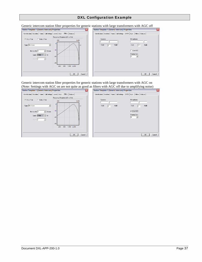
Generic intercom station filter properties for generic stations with large transformers with AGC off
Generic intercom station filter properties for generic stations with large transformers with AGC on (Note: Settings with AGC on are not quite as good as filters with AGC off due to amplifying noise)