Embed Size (px)
Citation preview

Microanatomy and histology of bone
pathologies of extant and extinct phocid seals
Megan R. Woolley1, Anusuya Chinsamy1, Romala Govender1,2, Marthán N. Bester3
1 Department of Biological Sciences, University of Cape Town, Cape Town, South Africa
2 Research and Exhibitions Department, Iziko Museums, Cape Town, South Africa
3 Mammal Research Institute, Department of Zoology and Entomology, University of Pretoria, Pretoria, South
Africa

Abstract
This study investigates three presumed fractured phocid seal bones: An isolated metapodial
and an ulna belonging to different individuals of the extinct phocid, Homiphoca capensis,
from Langebaanweg and a mandible of a juvenile elephant seal (Mirounga leonina), which
was included to assess the validity of the assumption that changes to bones caused by
fractures are consistent across extant and extinct members of the same groups. The bones
were studied using a multi-method approach, including gross morphology, microcomputed
tomography (micro-CT) and histology. Micro-CT showed that the metapodial was not
fractured and information drawn from other analyses suggested that the pathology was an
osteosarcoma. Histology of normal and fractured regions of the mandible and ulna permitted
an estimate about the fracture healing stage, and showed the bone tissue at the fracture sites to
be histologically similar. A birth line found on the lateral surface of the elephant seal
mandible emphasised its young age and marked the first example of a birth line in a bone of a
semi-aquatic mammal. A large scope of information was obtained using this multi-method
approach, which could permit insight into the life events and lifestyles of modern and extinct
individuals, such as H. capensis.
Key words: palaeopathology, pathology, phocid, bone histology, Homiphoca, elephant seal,
osteosarcoma

Introduction
Palaeopathology is the study of the evidence of injury and disease that inflicted ancient
man and fossil animals (Moodie 1923). It often discloses pertinent information about traumatic
events that occurred during the life of an extinct individual and such studies coupled with
knowledge of the modern relatives often allows for interpretations about extinct animal
behaviour, living conditions and life history traits to be made (Kierdorf et al. 2012).
The world renowned Mio-Pliocene (5.1-7 Ma) locality, Langebaanweg on the south-
western Cape coast of South Africa (SA), preserves abundant remains of vertebrates, including
the phocid seal Homiphoca capensis (Hendey 1982). Many studies have investigated the rich
vertebrates collected from Langebaanweg, however, investigations into palaeopathologies
evident among the fossils have been limited to studies of the teeth of sivatheres (Franz-
Odendaal et al. 2004) and skeletal pathologies in the phocid seals (Govender et al. 2011).
Homiphoca capensis is the only phocid seal known from Langebaanweg. It is relatively
abundant with 3131 complete and fragmentary bones (Govender et al. 2011). Curiously, despite
such a large number of H. capensis fossils, Govender et al. (2011) found only 23 specimens
with evidence of pathologies such as osteoarthritis, osteomyelitis, periodontitis and trauma,
such as healed fractures.
Using a combination of methods including gross morphology, micro-CT scanning and
histology here we assess the presumed “fractured and healed” ulna and metapodial of extinct
phocids from Langebaanweg (Govender et al. 2011), as well as the partially healed fractured
mandible of an extant juvenile southern elephant seal (Mirounga leonina). This multi-method
approach has been shown to be more valuable to modern palaeopathological research, than
the outdated single-method approach (i.e. gross morphology) (Straight et al. 2009). This is
particularly true for the diagnosis of ancient specimens (David and Zimmerman 2010;
Hedrick et al. 2016) and for understanding the macro-scale through to the micro-scale
(histological) responses of bones to different pathologies.
The main aim of this study is to assess how the skeletal damage influenced the gross
anatomy and microanatomy of these elements, as well as the histological changes associated
with the bone tissue around the injury and the healing stage of the fracture. It is assumed that
the skeletal response to fractures in the extinct phocid seals will not differ widely from that of
modern phocid seals. This is because the bones of vertebrates have the same basic
components and we do not expect the lifestyle of phocid seals to have changed much in the
last 5Ma. However, by including the modern fractured mandible in this study the validity of
this assumption can be assessed. The differences in the structure of the bone and the fracture
healing processes are predicted to be a result of the type of skeletal element fractured, the age
of the individual and the type of fracture (Lovell 1997).
Materials and methods
Specimens
The H. capensis fractured ulna (SAM-PQ-L32626) and metapodial (SAM-PQ-L40833)
are from the Cenozoic Palaeontology collections housed at Iziko South African Museums,
Cape Town, SA. The extant juvenile southern elephant seal specimen (PEMN986) from
Marion Island was housed at BayWorld Marine Mammal collection in Port Elizabeth, SA.
Anatomy and microanatomy
Lovell’s (1997) summary of the types and causes of fractures that commonly affect the
human skeleton was used to describe the nature of the fractures evident on the seal bones; guide
the identification of the mechanism of the different fractures; and finally assists in interpreting
the ultimate cause of the fractures. The five-stage fracture repair process outlined by Lovell

(1997, p. 145) is used in conjunction with histology to estimate the healing stages of the
fractured bones.
The pathological bones were photographed using a Nikon D90 digital camera. Each of
the specimens were micro-CT scanned at the University of Stellenbosch Scanning Facility (Du
Plessis et al. 2016) in Western Cape, SA. A General Electric V|TomeX L240 system was used
and optimized parameters were selected according to the guidelines set out by Du Plessis et al.
(2017). The specimens were scanned using the same settings; 80kV (voltage), 240µA (current)
and 100µm resolution. Volume Graphics (MyVGL) was used for the visualisation and analysis
of micro-CT scan data. Micro-CT images illustrated in this manuscript were captured by
MyVGL.
Histology
After micro-CT scanning, the specimens were serially sectioned following methods
outlined by Chinsamy and Raath (1992). The mandible had been defatted prior to the beginning
of this research, therefore we cannot comment on the method used for defatting this bone. For
each of the three bones, the ‘normal’ and pathological/fractured regions of each bone were
identified based on the external morphology and information provided by micro-CT scans (see
Figures 1C, 6C, 11C). Serial sections of both pathological and ‘normal’ regions of each bone
were made so that the ‘normal’ regions could be treated as a control with which the pathological
regions could be compared at a microstructural level. All thin sections were analysed using a
Zeiss Axio Lab.A1 petrographic microscope. Photomicrographs were taken using the Nikon
imaging software, NIS-Elements ver. 4. Composite images were produced using NIS-Elements
and Kolor Autopano Giga (APG). Microsoft Paint 3D was used for cropping the images;
combining the gross photographs, micro-CT images and histological images; and adding
labels, arrows and clear scale bars.

Results
Metapodial
Anatomy
The metapodial is a relatively cylindrical bone with a maximum length of 7.9cm; a
maximum width at the distal end of 2.8cm and a minimum width across the midshaft of 1.8cm.
Govender et al. (2011) described the pathological metapodial and suggested that it had a healed
fracture about a third of the way from the distal articulation causing a slight curvature at the
distal end of the bone, which was considered to have resulted from misalignment during healing
(Figure 1A, white arrows). There is extensive bone growth at the distal articulation, and
exostoses and pitting along the entire ventral surface of the bone giving this surface an uneven
texture. In contrast, the dorsal midshaft region is much smoother and suggests a non-
pathological surface (Figure 1A).
Figure 1. (A) Photographs of the H. capensis metapodial in ventral and dorsal view. The numbers written on the bone are purely for specimen identification. The solid white arrows indicate the region of the metapodial where Govender et al. (2011) suggested there to be a fracture. (B) Micro-CT image of a longitudinal section through the metapodial. The horizontal lines correspond with the transverse sections in Figure 1C and the labelled lines indicate the location of the thin sections shown in Figures 2, 3, 4 and 5. Micro-CT image suggests no evidence of trauma in the region indicated by white arrow, where a fracture was initially hypothesised. (C) Micro-CT transverse sections through different points along the metapodial. The so-called ‘normal’ and pathological bone is indicated using brackets on the right hand side and the directional arrows pertain to the

orientation of the transverse sections. The white outlined arrow shows the location of the original cortical bone in the transverse section at the distal end. Scale bars: A = 2cm; B, C = 1cm.
Microanatomy
Micro-CT scan data for the metapodial shows no evidence of a fracture and there is no
indication of trauma to the cancellous bone in this region (Figure 1B, white arrow). This
suggests that a different type of pathology caused the surface reaction evident on the
metapodial. Micro-CT transverse sections in Figure 1C show a change in the thickness of the
cortical bone from the proximal articulation, where the cortical bone is relatively thin, through
the midshaft of the bone, where the cortical bone becomes thicker and increasingly uneven
closer to the distal end. There is periosteal bone growth on the medial surface and subsequent
resorption of bone from the lateral edge of the medullary cavity (Figure 1C), which is
characteristic of osseous drift (Enlow 1963, p.51; Francillon-Vieillot et al. 1990). The
medullary cavity can be seen clearly through the midshaft, however, it is not evident in the
more distal reaches of the bone although part of the original compacted cortical bone is still
visible in the centre the distal transverse section (Figure 1C, white outlined arrow). Large
cavities are visible in the distal end of the metapodial and this region is more porous than the
midshaft.
Histology
Contra our initial gross morphological assessment, histological analysis of the midshaft
region of the metapodial revealed the ventral surface was pathological (Figure 2A). Exostoses
are observed on the ventral surface (Figure 1A, 2A), but it is apparent that an endosteal reaction
also occurred along the edges of the medullary cavity and extended into the perimedullary
region. The periosteal reaction tissue near the ventral surface is lighter in colour and appears
to be more porous than the underlying bone in the perimedullary region (Figure 2A, 2D). The
dorsal region of the section in Figure 2A appears to have a smooth surface (Figure 1A, dorsal
midshaft) and a fairly homogenous texture between the perimedullary region and the periosteal

surface of the bone. A prominent outer circumferential layer can be seen on the dorsal surface,
which is made up of lamellar bone with at least one visible rest line (Figure 2E).
Figure 2. (A) A section from the metapodial of what initially appeared to be ‘normal’ bone (see Figure 1B for locational information). Box frames indicate positions of images indicated in Figures 2B-E under cross-polarised light. Black arrows point to the exostoses seen on the ventral surface of the metapodial. (B) Dorsal region of the metapodial, which is suggested to be the most unaltered state of the metapodial at the level of histology due to the smooth bone periphery, which is magnified in Figure 2E. There are clusters of secondary osteons (white outlined arrow) and compacted coarse cancellous (ccc) bone in this region. (C) Secondarily reconstructed trabeculae, evident by redeposition of lamellar bone along the trabeculae walls. (D) Ventral region of the metapodial, shows compacted coarse cancellous bone between medullary cavity (mc) and uneven bone peripheral surface, as well as many resorption cavities. (E) Dorsal region at high magnification also showing compacted coarse cancellous bone, but with a smooth outer circumferential layer of lamellar bone with one rest line indicated by the white arrow. ccc, compact coarse cancellous; mc, medullary cavity. Scale bars: A= 5mm B, D = 1mm; C, E = 500µm.

There is widespread secondary reconstruction throughout the dorsal compacta of the
bone wall (Figure 2A), which is evident by the presence of clusters of secondary osteons
(Figure 2B, white outlined arrow) and there is also secondarily reconstructed cancellous bone
present (Figure 2C). Figure 2D shows a high magnification image of the abnormal bone growth
on the ventral surface of the metapodial. The bone in this region has a woven texture and a high
degree of disorganised vascularisation giving it a distinct swirling appearing. There are also
enlarged resorption cavities present that vary in shape and size and some of them are lined with
endosteally deposited lamellar bone (Figure 2D).
Section 3A (see Figure 1B for location) has a similar overall texture to that of section
2A (Figures 1C, 2A), however, it differs in shape since the pathology is more prolific in this
region (see Figure 1C). The radially arranged resorption cavities around the perimedullary
region are more elongate and extend further into the cortical bone towards the bone surface,
particularly in the dorsolateral region (Figure 3A).
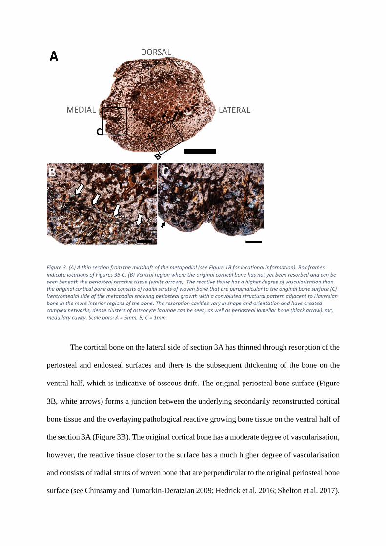
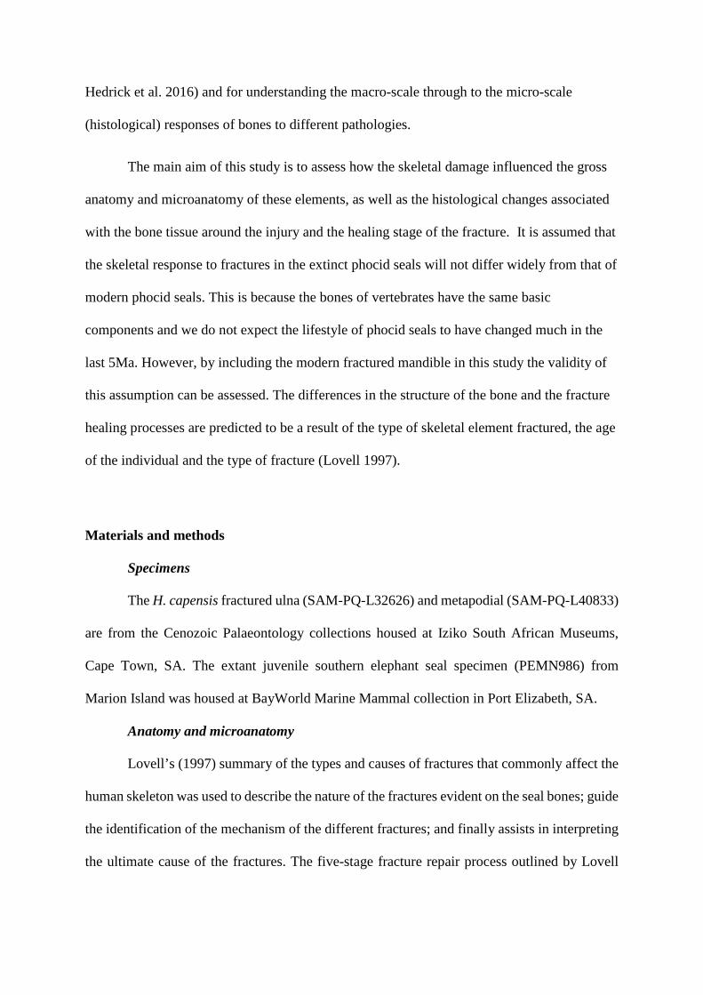
Figure 3. (A) A thin section from the midshaft of the metapodial (see Figure 1B for locational information). Box frames indicate locations of Figures 3B-C. (B) Ventral region where the original cortical bone has not yet been resorbed and can be seen beneath the periosteal reactive tissue (white arrows). The reactive tissue has a higher degree of vascularisation than the original cortical bone and consists of radial struts of woven bone that are perpendicular to the original bone surface (C) Ventromedial side of the metapodial showing periosteal growth with a convoluted structural pattern adjacent to Haversian bone in the more interior regions of the bone. The resorption cavities vary in shape and orientation and have created complex networks, dense clusters of osteocyte lacunae can be seen, as well as periosteal lamellar bone (black arrow). mc, medullary cavity. Scale bars: A = 5mm, B, C = 1mm.
The cortical bone on the lateral side of section 3A has thinned through resorption of the
periosteal and endosteal surfaces and there is the subsequent thickening of the bone on the
ventral half, which is indicative of osseous drift. The original periosteal bone surface (Figure
3B, white arrows) forms a junction between the underlying secondarily reconstructed cortical
bone tissue and the overlaying pathological reactive growing bone tissue on the ventral half of
the section 3A (Figure 3B). The original cortical bone has a moderate degree of vascularisation,
however, the reactive tissue closer to the surface has a much higher degree of vascularisation
and consists of radial struts of woven bone that are perpendicular to the original periosteal bone
surface (see Chinsamy and Tumarkin-Deratzian 2009; Hedrick et al. 2016; Shelton et al. 2017).

The cancellous spaces on the dorsolateral side of the perimedullary region extend
outwards toward the lateral surface of the bone (Figure 4). There is a periosteal reaction
associated with these extended cancellous spaces, which manifested as additional bone growth
on the dorsolateral surface that appears to follow the same directional pattern as the cancellous
spaces (Figure 4, area under grey curve). A distinct bony projection can be seen on the
ventromedial surface of the metapodial (Figure 4, white arrow). It is formed predominantly
from primary bone with scarcely distributed secondary osteons, although many large erosion
cavities are present giving the out-growth an overall cancellous texture. The growth attaches
to the ventromedial side of the main bone fragment with a woven bone matrix consisting of
dense clusters of osteocyte lacunae and many disarrayed vascular canals that create a distinct
whirling pattern.
Figure 4. Thin section taken from the metapodial shaft near the distal end where the abnormal bone growth is more prominent (see Figure 1B for locational information). There is a reaction from the interior of the bone outwards to the periphery, resulting in warped cancellous spaces at the perimedullary region into the cortex, which have the same directional pattern at the lumpy reaction on the dorsolateral surface (under grey bracket). There is a distinct bony projection coming out from the ventromedial surface (black outlined arrow). Scale bar: 5mm.

All longitudinal sections (see Figure 1B for locational information) through the distal
articulation show the bone in this region to be extremely spongious, with little secondary
reconstruction. Large, haphazardly arranged resorption cavities can be seen throughout the
sections and are largest in the centre, possibly due to resorption of trabeculae in the medullary
cavity (Figure 5A, 5B). The bone tissue between the resorption cavities is predominantly
woven bone and some are lined by endosteally formed lamellar bone. The original cortical
bone (5A-B, black arrows), initially noted in the micro-CT transverse images (Figure 1C, white
outlined arrow) can be seen in the longitudinal sections. Its texture resembles the ‘normal’ bone
seen on the dorsal half of the section in Figure 2B, but it has a lower degree of vascularisation
(Figure 5C).
Figure 5. Longitudinal sections taken through the distal articulation of the metapodial (see Figure 1B for locational information). (A) Longitudinal section taken on the side of the distal articulation where the bone proliferation on the surface was more prominent. (B) Narrower longitudinal section taken on the side of the distal articulation where the abnormal bone growth was less prominent. Labelled box frames indicate location of 5C. Bone at the distal articulation is highly porous with many resorption cavities that are larger near the centre. The bone periphery is very uneven. (C) There is a patch of original cortical bone (Figure 5A-B, black arrows), seen in a micro-CT transverse section (see Figure 1C, white outlined arrow), which
appears to be a different bone tissue with comparably fewer vascular canals and resorption cavities than the surrounding bone. There are osteocyte lacunae concentrated around the edges of the cavities. Scale bars: A, B = 5mm, C = 500µm.
Ulna
Anatomy
The ulna has a maximum length of 12.1cm and a maximum width across the proximal
articulation of 4.2cm. The partially healed fracture towards the proximal end of the ulna
(Govender et al. 2011) appears to have occurred in such a way that the distal and proximal ends
have been twisted in opposite directions (Figure 6A), suggesting that it is a spiral fracture
(Lovell 1997). It is likely that the muscles remained intact at the time of injury preventing the
fracture fragments from moving away from each other, which left the bone deformed (Lovell
1997).
Figure 6. (A) Photographs of the fractured H. capensis ulna in lateral and medial view. (B) Three-dimensional micro-CT image of the fractured ulna in posteromedial view to show the detail around the fracture. The horizontal lines correspond with the transverse sections in 6C and the labels indicate the location of the thin sections made from the ulna shown in Figures 8, 9 and 10. (C) The transverse micro-CT sections show a dramatic change in shape from the proximal articulation, through the fracture site and the ‘normal’ bone. The directional arrows pertain to the ‘normal’ and fractured transverse sections. These are slightly different as a result of the fracture. The white arrow heads in Figure 6A-C point to the proximal fracture fragment and the grey arrow heads point to the distal fracture fragment; these assist in the understanding of the orientation of fractured ulna in the transverse and histological sections. Scale bars: A, B = 10cm; C = 2cm.
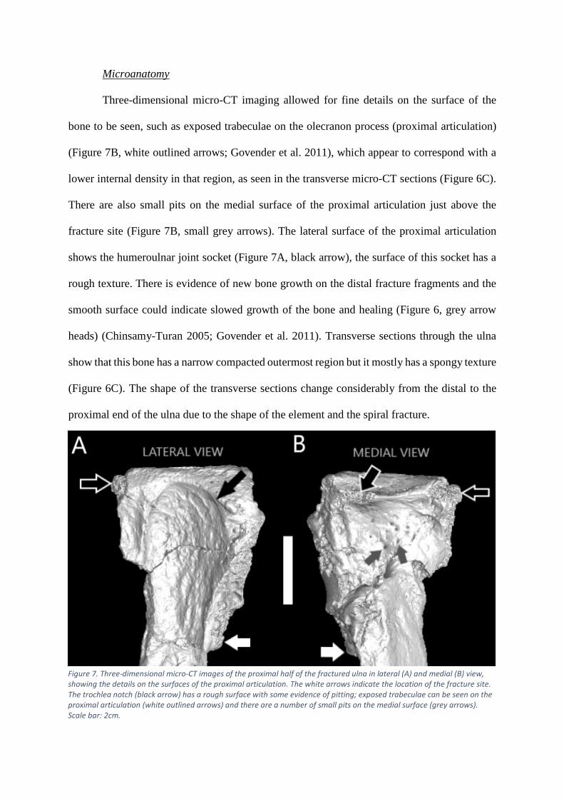
Microanatomy
Three-dimensional micro-CT imaging allowed for fine details on the surface of the
bone to be seen, such as exposed trabeculae on the olecranon process (proximal articulation)
(Figure 7B, white outlined arrows; Govender et al. 2011), which appear to correspond with a
lower internal density in that region, as seen in the transverse micro-CT sections (Figure 6C).
There are also small pits on the medial surface of the proximal articulation just above the
fracture site (Figure 7B, small grey arrows). The lateral surface of the proximal articulation
shows the humeroulnar joint socket (Figure 7A, black arrow), the surface of this socket has a
rough texture. There is evidence of new bone growth on the distal fracture fragments and the
smooth surface could indicate slowed growth of the bone and healing (Figure 6, grey arrow
heads) (Chinsamy-Turan 2005; Govender et al. 2011). Transverse sections through the ulna
show that this bone has a narrow compacted outermost region but it mostly has a spongy texture
(Figure 6C). The shape of the transverse sections change considerably from the distal to the
proximal end of the ulna due to the shape of the element and the spiral fracture.
Figure 7. Three-dimensional micro-CT images of the proximal half of the fractured ulna in lateral (A) and medial (B) view, showing the details on the surfaces of the proximal articulation. The white arrows indicate the location of the fracture site. The trochlea notch (black arrow) has a rough surface with some evidence of pitting; exposed trabeculae can be seen on the proximal articulation (white outlined arrows) and there are a number of small pits on the medial surface (grey arrows). Scale bar: 2cm.
Histology
Histological analysis of the ulna supports the micro-CT observation that the bone has a
spongy texture (Figure 8A). The cortex has a convoluted pattern similar to that figured and
described by Enlow (1963, p.36-37), suggesting that it is compacted coarse cancellous bone
scattered with small resorption cavities (Figure 8B). Abundant primary (short arrow) and fewer
secondary (long arrow) osteons are visible within the cortical bone (Figure 8C). Fibrolamellar
bone is the dominant tissue type in the distal fracture callus (Figure 8D). There is a high degree
of reticular vascularisation and dense clusters of osteocyte lacunae (short outlined arrow) and
Sharpey’s fibres (long outlined arrow) are present. A few small resorption cavities can be seen
here (Figure 8D, rc), although they are not as numerous as the medial cortical bone and do not
have endosteally formed lamellar bone, which indicates that these cavities were being actively
resorbed at the time of death. However, there is lamellar bone at the periosteal surface with at
least one rest line (Figure 8D, black arrow) indicating a smoothing of the surface and suggesting
slowed growth (Chinsamy-Turan 2005) and healing (Govender et al. 2011). Secondary
reconstruction of the trabeculae (Figure 8E) is noted throughout the bone.

Figure 8. (A) A thin section of ‘normal’ bone from the fractured ulna under cross-polarised light (see Figure 6B for locational information). Box frames indicate the positions of Figures 8B-E. (B) The cortical bone on medial ulna consists of compacted coarse cancellous bone (ccc), a few resorption cavities (rc) and scarce secondary osteons. (C) Cortical bone on the posterior side of the ulna. Woven-fibred bone tissue with primary (short arrow) and secondary (long arrow) osteons. (D) Fracture site with resorption cavities (rc), dense clusters of osteocyte lacunae (short outlined arrow) and Sharpey’s fibres (long outlined arrow). Bone tissue changes from woven-fibred to a lamellar type tissue near the periosteal surface showing at least one rest line (black arrow). (E) Secondarily reconstructed trabeculae. ccc, compact coarse cancellous; rc, resorption cavities. Scale bars: A = 5mm; B, C = 100µm; D, E = 250µm.

The proximal fracture fragment can clearly be seen on the anterolateral side of section
Figure 9A (see Figure 6C for locational information). Original secondarily reconstructed
cancellous bone is observed within the fracture fragment (Figure 9A, black outlined arrows),
however, resorption has occurred along the walls of the trabeculae. The cortical bone in this
section is like that seen in Figure 8B and 8C. It has fewer secondary osteons and no periosteal
lamellar bone on the surface or endosteally deposited lamellar bone around the edges of the
resorption cavities. There is a section of bone in the region of the fracture site that appears to
be woven-fibred bone with a high degree of reticular vascularisation (Figure 9C), suggesting
that it was rapidly deposited (Chinsamy-Turan 2005) to bridge the gap between the fracture
fragments.
Figure 9. (A) Thin section showing the proximal fracture fragment on the lateral side of the ulna (see Figure 6B for locational information). Box frames indicate position of Figures 9B-C and black outlined arrows point to original cancellous spaces within the proximal fracture fragment. (B) Cortical bone on anterior edge of the ulna shows reticular woven-fibred bone with a few resorption cavities and primary osteons. (C) The region between the distal and proximal fracture fragments. This region became quite cracked during the sectioning process, however, under cross-polarised light disorganised woven-fibred bone with many osteocyte lacunae and Sharpey’s fibres (black outline arrows) can be seen and there is a high degree reticular vascularisation in this region. Scale bars: A = 5mm; B, C = 1mm.
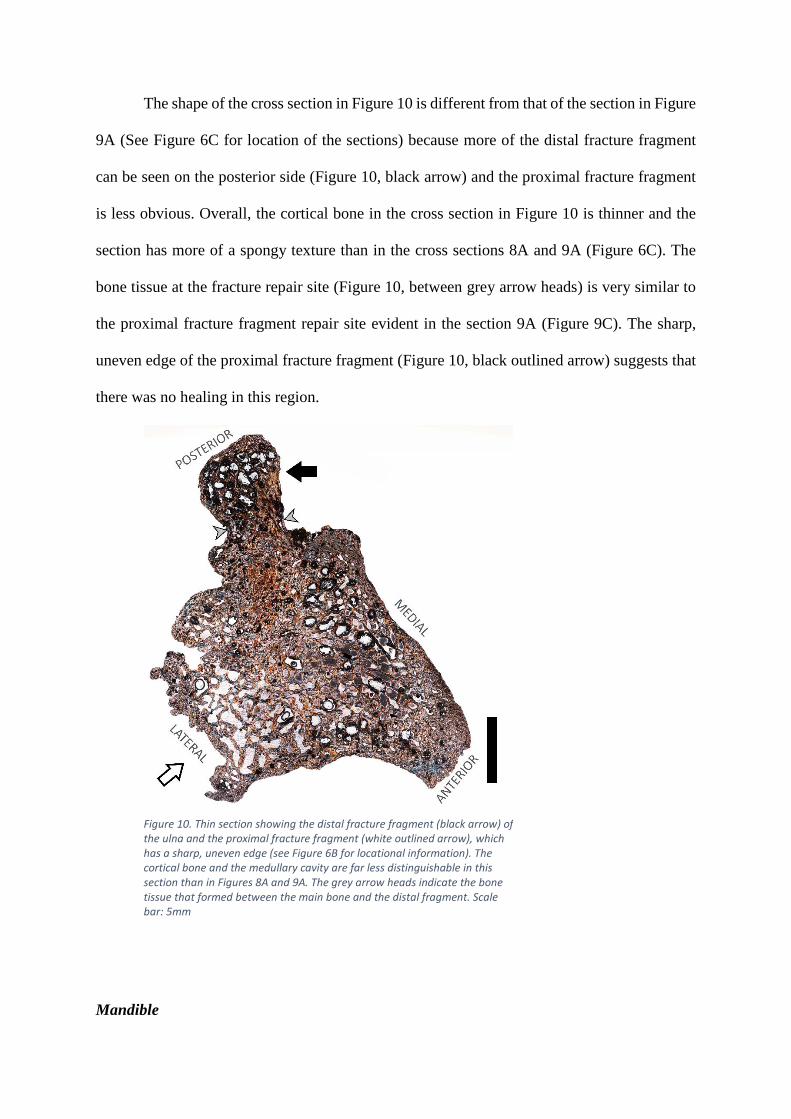
The shape of the cross section in Figure 10 is different from that of the section in Figure
9A (See Figure 6C for location of the sections) because more of the distal fracture fragment
can be seen on the posterior side (Figure 10, black arrow) and the proximal fracture fragment
is less obvious. Overall, the cortical bone in the cross section in Figure 10 is thinner and the
section has more of a spongy texture than in the cross sections 8A and 9A (Figure 6C). The
bone tissue at the fracture repair site (Figure 10, between grey arrow heads) is very similar to
the proximal fracture fragment repair site evident in the section 9A (Figure 9C). The sharp,
uneven edge of the proximal fracture fragment (Figure 10, black outlined arrow) suggests that
there was no healing in this region.
Mandible
Figure 10. Thin section showing the distal fracture fragment (black arrow) of the ulna and the proximal fracture fragment (white outlined arrow), which has a sharp, uneven edge (see Figure 6B for locational information). The cortical bone and the medullary cavity are far less distinguishable in this section than in Figures 8A and 9A. The grey arrow heads indicate the bone tissue that formed between the main bone and the distal fragment. Scale bar: 5mm

Anatomy
The juvenile elephant seal mandible has a maximum length from the mandibular
condyle to the anterior most tip of approximately 14.9cm; and a height from the ventral surface
to the interdental space between the second and third tooth socket of 3.4cm. The fracture on
the mandible occurred on the lateral side of the bone and has a horizontal ‘V’ shape (Figure
11A, grey box). It starts on the ventral side of the mandible in the region after the fourth
premolar and ends on the dorsal side between the third and fourth premolar tooth sockets. It is
classified as a greenstick fracture, as described by Lovell (1997). These fractures are usually
incomplete and involve only the convex side of the bone, in this case the lateral side. There are
several elongated depressions that look like exposed channels, and pores on the medial side of
the bone. The bone appears to be more porous along the ramus and near the condyles, however,
this is probably due to the young age of the seal, instead of a consequence of the injury (Figure
11A, black arrow head).
Figure 11. (A) Photograph of the lateral side of the juvenile M. leonina fractured right mandible. The fracture (grey box) is shaped like a horizontal ‘V’. The black arrow heads indicate the region where the bone is quite porous. The numbers written on the bone are purely for specimen identification purposes. (B) Longitudinal micro-CT section through the mandible showing the location of the fracture and how it passes through the bone from ventral to dorsal side. The horizontal lines indicate the level of every fourth transverse section shown in Figure 11C and specifically indicate the positions of the histological thin sections in Figures 13, 14 and 15. White arrow indicates damage to the region near the alveolus of the canine. (C) Twelve micro-CT transverse images were produced at 2mm intervals from the normal portion of the bone (I), through the fracture site (II-XII). Damage to the internal structures of the mandible can be observed, such as the mandibular (large channel opening) and mental (small channel opening) foramina, which can be seen in a normal state in I. Scale bars: 2cm.

Microanatomy
The exact age of this animal is unknown, however, the size of the mandible in
comparison to an adult elephant seals suggests that it is a juvenile (Tarnawski et al. 2014),
despite the large canine visible at the anterior of the mandible. According to Scheffer and
Myrick (1980) these permanent canines can erupt when a pup is as young as eight days old.
The canine is split (Figure 12A, white arrow) possibly due to drying out of the specimen
causing it to crack or due to the fracture, which appears to have caused some damage near the
alveolus of the tooth as can be seen in the longitudinal micro-CT section (Figure 11B, white
arrow). The magnified three-dimensional micro-CT image in Figure 12B (black arrows) shows
partial healing of the fracture by tiny struts of bone that have grown between the fracture
fragments.
Micro-CT transverse sections were taken through the mandible (Figure 11C). The
mandible appears to become increasingly swollen anteriorly in the cross sections, although this
is a natural feature as the anterior half of the mandible supports the teeth (Abbott and Verstraete
2005). Thus we cannot say how much or if any of the “swelling” had been caused by the
Figure 12. (A) Three-dimensional micro-CT image of the dorsal side of the fractured mandible showing the split canine (white arrow) and dorsal view of fracture between the third and fourth premolar (black arrow). The box frame shows the position of the high magnification image in Figure 12B. (B) High magnification three-dimensional micro-CT image of the fracture on the mandible showing tiny struts of bone growing in between the two fracture fragments (black arrows) as if to “stitch” the bone together. Scale bars: A = 1cm; B = 2mm.

fracture. However, it is clear that the fracture caused damage to the mandibular and, more so
to the mental foramina (Figure 11C).
Histology
The mandible is predominantly comprised of primary bone and the texture is typical of
a young rapidly growing individual (Chinsamy-Turan 2005). It consists primarily of a woven
cancellous framework with a narrow layer of compacted cortical bone around the perimeter,
which is thicker on the lateral side of the bone (Figure 13). The mandibular and mental
foramina supply blood to the lower face and allow for sensory innervation (Phillips et al. 1990)
and are intact in the normal section (Figure 13, see Figure 11C for locational information). The
medial side of this bone has two small notches in the surface (Figure 13, black arrows).
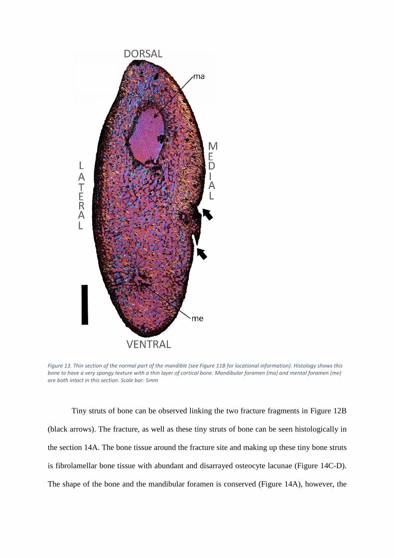
Figure 13. Thin section of the normal part of the mandible (see Figure 11B for locational information). Histology shows this bone to have a very spongy texture with a thin layer of cortical bone. Mandibular foramen (ma) and mental foramen (me) are both intact in this section. Scale bar: 5mm
Tiny struts of bone can be observed linking the two fracture fragments in Figure 12B
(black arrows). The fracture, as well as these tiny struts of bone can be seen histologically in
the section 14A. The bone tissue around the fracture site and making up these tiny bone struts
is fibrolamellar bone tissue with abundant and disarrayed osteocyte lacunae (Figure 14C-D).
The shape of the bone and the mandibular foramen is conserved (Figure 14A), however, the

fracture passes through the bone from the lateral side, through the mental foramen (possibly a
biomechanically weak point), to the ventral surface, leaving the mental foramen deformed.
There is a distinct line that runs parallel to the lateral surface of the mandible, which is
indicated by black outlined arrows (Figure 14B). This resembles a birth line, which is a non-
cyclical growth mark deposited around the time of birth and has been recently noted in juvenile
equid limb bones (Nacarino-Meneses and Köhler 2018). This line can be seen on the lateral
side of the bone throughout most serial sections where the cortical bone is not disrupted by the
fracture. The presence of this birth line emphasises the young age of this individual.
Further deformation of the bone is evident in section 15A (see Figure 11C for locational
information). The mandibular foramen has changed in shape due to endosteal resorption
(Figure 15A, black arrow). On the medial side of the section the small notch can be observed
Figure 14. (A) Thin section taken through the fracture site of the mandible (see Figure 11B for locational information). Labelled box frames indicate the positions of Figures 14B-D. The mandibular foramen is relatively normal in terms of shape; however, the mental foramen has been damaged by the fracture. (B) High magnification image of the bone tissue around the birth line on the lateral surface of the mandible (black outline arrows). (C) The fracture site, struts of bone seen in Figure 12B are shown histologically. Dark regions of the section are indicative of dense clusters of osteocyte lacunae and Sharpey’s fibres. (D) Fracture site at a higher magnification to see clusters of individual osteocyte lacunae (black outlined arrow heads). Scale bars: A = 5mm; B, C = 1mm; D = 500µm.

(Figure 15A, black outlined arrow). In section 14A this notch was open, however, Figure 15B
shows that it is enclosed by fibrolamellar bone with many dense clusters of osteocyte lacunae
(Figure 15B, white arrows) suggesting partial healing. The cancellous spaces are more variable
in shape and size in section 15A. This is especially clear in the centre of the section, ventral to
the mandibular foramen (Figure 15C, black arrow) where there is a distinct change in the angles
of the trabeculae.
Discussion
Metapodial
Figure 15. (A) Thin section taken through the fracture site of the mandible (see Figure 11B for locational information). Box frames indicate positions of Figures 15B-E. The shape of the mandibular foramen differs from the previous sections due to endosteal resorption (black arrow). The mental foramen is no longer evident due to damage caused by the fracture. The small notch on the medial side of the bone enclosed (black outlined arrow). (B) Fibrolamellar bone tissue with dense clusters of osteocyte lacunae (white arrows) in relatively parallel lines sealing the opening of the notch on the medial side of the mandible. (C) Change in direction of growth shown by abrupt change in the angle of trabeculae near the mandibular foramen (black arrow). Scale bars: A = 5mm; B = 500µm; C = 1mm.

Micro-CT imaging permitted the exclusion of a fracture as the cause of the pathology
(Figure 1B). The enlarged distal articulation was the result of additional bone growth being
more pronounced on the left, thus causing the bone to appear slightly bowed. The unusual bone
growth and abnormal bony surface projections (exostoses) were caused by a pathological
response, for which there is circumstantial, morphological, radiological (micro-CT) and
histological evidence to suggest that it was the result of an osteosarcoma, a type of primary
bone tumour (Coomber et al. 1998).
Circumstantial evidence:
Different cancers have been reported across the entire spectrum of vertebrates (Capasso
2005) and osteosarcomas are the most common type of bone cancer, which manifest as the
rapid production of immature bone by tumour cells (Klein and Siegal 2006). Osteosarcomas
can form spontaneously due to random cell mutations during fast growth through ontogeny,
thus formation via this mechanism can predispose a range of different organisms to developing
osteosarcomas (Coomber et al. 1998; Klein and Siegal 2006). They are especially prevalent in
carnivorous mammals, such as dogs and cats (Coomber et al. 1998) but are seldom detected in
prehistoric and wild organisms (Capasso 2005). However, we suggest that this may be due to
the limitations of studying bone pathologies in wild animals as opposed to domesticated
animals, as feral afflicted animals may be more susceptible to predation (Capasso 2005).
Among extinct animals, since soft tissues are not preserved, only cancers that affect bone can
be detected. The presence of osteosarcomas in fossil vertebrates e.g. in a Triassic stem turtle
(Haridy et al. 2019) suggests that cancer is not a modern physiological phenomenon but is
ancient.
Capasso (2005) reviewed much of the research on cancer in wild and fossil animals and
notes that there is much scepticism around the scientific literature that has tried to deal with
examples of osteosarcomas in extinct animals (David and Zimmerman 2010). However, we
argue that the diagnostic frameworks for osteosarcomas by modern medicine and veterinary
science cannot be applied strictly in palaeopathological research. For example, among modern
vertebrates, the diagnosis of osteosarcoma is confirmed by the histological detection of tumour
cells. Such diagnoses cannot be made when dealing with extinct vertebrates since the soft tissue
cells do not preserve. Additionally medical practitioners use other symptoms (unavailable for
palaeontologists) such as, a bone mass accompanied by a reduction/loss of function, reduced
range of motion and/or complaints of severe pain especially at night as forewarnings of
osteosarcomas (Klein and Siegal 2006).
Morphological evidence:
Osteosarcomas can occur on the bone surface (e.g. parosteal and periosteal
osteosarcomas) (Rothschild and Martin 1993; Klein and Siegal 2006), as well as in the
intramedullary region or intracortical compartment near the metaphyseal regions of the tubular
bones (Klein and Siegal 2006). Haridy et al. (2019) noted a periosteal osteosarcoma on a stem-
turtle from the Triassic, with a similar external morphology to the metapodial. There is
abnormal bone growth on the dorsal side of the bone’s proximal half, which formed bony
projections on the surface resulting in a lumpy texture like that seen on the surface of the distal
metapodial i.e. not a ‘sunburst’ pattern often typified in discussions around osteosarcomas
(Rothschild and Martin 1993; Capasso 2005).
Two dissected human humeri from Human Pathology (2006) with osteosarcomas near
the metaphyseal and proximal articular surface regions also share similarities in gross
morphology with the H. capensis metapodial. These similarities include: the lumpy texture of
the extensive bone growth on the bones’ exterior, especially around the metaphyseal regions
and articular surfaces, as well as the abnormal periosteal reactions observed along the shafts of

the two bones. Internally, the tumours both indicated an increase in volume, but a decrease in
density due to extensive internal resorption, leaving large cavities throughout (Figure 5A, 5B).
Thus, although the original cortical bone is still evident within the bone mass, large portions of
it have been resorbed in both the humeri and the H. capensis metapodial (Figure 5A, 5B).
Radiographic evidence:
Micro-CT imaging was used instead of x-rays since it permitted a three-dimensional
microanatomical view of the metapodial. The micro-CT images showed the regions of the
metapodial that were denser and those regions, like the tumour, that were quite porous. The
latter would translate on a radiograph as having a fluffy or more so a cloudy appearance (Klein
and Siegal 2006). Transverse micro-CT sections showed evidence for osseous drift, which was
caused by the intense bone growth on the medial side of the distal metapodial.
Histological evidence:
The resorption cavities and vascular canals were haphazardly arranged within a primary
bone matrix that was the periosteal reactive tissue overlying the partially resorbed original
cortical bone throughout most of the sections. This histological description is typical of rapidly
deposited pathological bone, which supports the diagnosis that an osteosarcoma was the cause
of this reactive growth. We propose that the secondary reconstruction in the form of secondary
osteons and periosteal lamellar bone near the dorsal midshaft had occurred prior to the
development of the osteosarcoma.
The reactive tissue overlying the original cortical bone is like the observations made on
a caudal vertebra with strange neoplastic lesions belonging to a titanosaurid dinosaur (de Souza
Barbosa et al. 2016). De Souza Barbosa et al. (2016) suggested that the abnormality could be
the result of an osteoma – whereby tumour cells produce a benign slow-growing lesion
(Greenspan 1993) or a hamartoma – whereby there is a localised exaggeration of normal bone

forming a lesion (Eshed et al. 2002). On the basis of its histology they identified it as an
osteoma due to its micro-trabecular pattern, which is similar to the “lacy pattern” of an
osteosarcoma described by Klein and Siegal (2006). De Souza Barbaso et al. (2016) also noted
a high degree of vascularisation and extensive osteocyte lacunae. Although the histology of the
osteoma of the titanosaurid vertebra resembles that of the metapodial, the gross morphology
differs from an osteoma, which are generally much smaller and hence often referred to as
‘button’ lesions (Eshed et al. 2002).
The section of the metapodial in Figure 4 (under the grey bracket) showed that the
cancellous spaces were warped by the direction of growth of the pathological bone, which
erupts at the dorsolateral surface as hyper-vascularised lumpy growths. According to Klein and
Siegal (2006) it is not unusual for a tumour to permeate the cancellous spaces in the medullary
cavity, as well as the Haversian systems and Volkmann’s canals from the medullary region
outwards (Klein and Siegal 2006). This pattern appears to have occurred along much of the
dorsolateral surface of the metapodial (Figure 3A, 4).
Ulna
Spiral fractures, as seen on the H. capensis ulna usually occur as a result of indirect
rotational forces on the longitudinal axis of the bone (Lovell 1997). The fracture resulted in a
malunion between the two fracture fragments. If the seal had survived long enough for
complete healing to occur, the bone would have been deformed and possibly shortened.
Mineralised woven-fibred bone made up most of the fracture callus. This rapidly forming bone
showed a high degree of reticular vascularisation (Figures 8B, 9C), which is an important factor
in the repair process as a large supply of blood is required for effective healing (Keramaris et
al. 2008). The distal fracture site in section 8A revealed a thin layer of periosteal lamellar bone
on the surface, with at least one rest line (Figure 8D), suggesting a pause in osteogenesis in this
region (Chinsamy-Turan 2005). In contrast, the proximal fracture fragment had a sharp edge,

which suggests that limited healing had taken place. The twisting of the two ends of the bone
may have caused severe damage to the skeletal muscles around the fracture. It appears that the
proximal half of the fractured bone may have caused more soft tissue damage than the distal
half (Figure 10). Soft tissue damage can lead to reduced perfusion of blood to the muscle
around the broken bone, thus hindering the fracture repair process (Schaser et al. 1983) on the
proximal fracture fragment (Figure 10).
Based on histology and fracture repair processes described by (Lovell 1997) we propose
that the ulna had reached the early stages of the fourth phase of fracture repair, i.e. the
consolidation stage. This means that the hematoma formed at the time of injury (stage 1) had
been replaced by osteoid deposited around the fracture fragments (stage 2), which had then
undergone mineralisation to form a woven bone callus (stage 3). The consolidation stage (stage
4) involves the remodelling of the woven bone fracture callus into mature lamellar bone. Stage
4 is complete when the fracture fragments are fully united. In the case of the ulna, the fracture
fragments are not fully united and there is only evidence of lamellar bone on the periosteal
surface of the fracture callus in one section (Figure 8D), suggesting that the consolidation stage
had only just commenced when the seal died.
The morphology of the fractured ulna suggests that the fracture caused additional
damage on the bone. The rough and misshapen humeroulnar joint contours, exposed trabeculae
and reduced internal density in this region, as well as pitting on the surface of the trochlea notch
(Figure 7A, 7B) is suggestive of erosive arthritis (Carter et al. 2008; Waldron 2008, pp. 27, 33;
Govender et al. 2011), as opposed to osteoarthritis, which is characterised by the proliferation
of bone and the presence of osteophytes (Carter et al. 2008). Carter et al. (2008) suggested that
moderate to more severe cases of arthritis are often secondary and related to trauma. Therefore
excessive resorption of the cortical bone (and some cancellous bone) in this region may have
led to the exposure of the proximal trabeculae as bone pathologies disrupt the normal

remodelling balance (Waldron 2008). Additionally, the spiral fracture likely also caused the
proximal articulation to move abnormally, thus wearing down the cortical bone by abrasion.
It appears that while woven-fibred bone was being deposited to form a fracture callus
around the fracture site, bone was being resorbed in other areas. The areas where resorption
was taking place include the cancellous bone; the cortical bone around the humeroulnar joint;
the proximal fracture fragment and even the periosteal surface in some places. Resorption in
areas not directly associated with the fracture site may have been a secondary response to the
presence of the fracture.
Mandible
The greenstick fracture on the mandible is an incomplete fracture involving the lateral
(convex) side of the bone. These types of fractures usually occur because of bending of the
bone due to longitudinal compression or angular force (Lovell 1997). According to Lovell
(1997), these fractures are common in young individuals, because their bones are pliable and
therefore, less likely to break. Histology strongly supported the morphology (size and surface
texture) in showing that this mandible belonged to a very young individual.
The fracture repair stage for this mandible is estimated to be in late second stage - early
third stage of repair. The woven-bone callus had only just started forming at the time of death,
which was noted by the tiny struts of woven-bone between the fracture fragments (Figure 12B).
However, the fracture callus was not completely formed because gaps can be seen between the
woven-bone struts. The dense clusters of osteocyte lacunae around the fracture site and within
these struts of bone (Figure 14D, white arrow heads) are characteristic of the second stage of
repair (Lovell 1997).
Regional changes in cancellous bone organisation are observed in the mandible (Figure
15C). This histological feature has been noted in other pathologies such as in the early stages
of osteoarthritis (Ding et al. 2003). It involves an increase in the thickness and density of the

trabeculae but a decrease in the connectivity of the trabeculae (Ding et al. 2003), which is
indicated in Figure 15C (black arrow). Elongated depressions on the medial surface of the
mandible can be seen histologically in section 15A and show partial healing by fibrolamellar
bone deposition around the endosteal surface of the notch (Figures 15B). These might be a
product of trauma, however, this indentation could also be an exposed channel for nerves
and/or blood vessels that is open, possibly due to the young age of the seal and would have
become fully enclosed with age had the seal pup survived.
An unexpected finding during the histological analysis of fractured mandible was the
presence of a birth line (Figure 14B), a non-cyclical bone growth mark deposited at the time of
birth and is similar to the neonatal line described in teeth (Scheffer and Myrick 1980). This is
significant as it has only recently been studied and described in bone tissue of young equids
(Nacarino-Meneses and Köhler 2018), which makes this the first time a birth line has been
noted in the bone of a semi-aquatic marine mammal. This feature emphasises the young age of
this individual, as these birth lines are often resorbed fairly soon after birth (Nacarino-Meneses
and Köhler 2018). This allowed us to deduce that the seal pup was very young at the time of
injury and that it had not lived for long thereafter.
Conclusion
Similarities across different pathologies
Even though the bones were not all inflicted with the same pathology, there were still
anatomical, microanatomical and histological similarities across the pathological specimens.
These included the rough surface texture seen on both the ulna and metapodial, as well as the
lower internal density, which was noted as a result of the traumatic arthritis on the proximal
ulna and the osteosarcoma on the distal metapodial. Histologically, the presence of dense
clusters of osteocyte lacunae and an increase in the abundance of Sharpey’s fibres, which have
been suggested to be pathological features (Aoki et al. 1987; Cerda et al. 2014) were noted at

the fracture repair sites of the ulna and mandible, as well as the regions of periosteal and
endosteal reactions on the metapodial.
These similarities seen across different pathologies emphasises the importance of using
a multi-method approach to palaeopathological research. The use of any of these methods in
isolation would have likely led to a different diagnosis, especially for the metapodial.
Fractures
Additionally, the multi-method approach facilitated the estimation of the healing stage
(Lovell 1997) of the fractures on the mandible and ulna; and assisted in the assessment of the
damage to the rest of the bone. Damage to the ulna included traumatic arthritis at the
humeroulnar joint (Carter et al. 2008; Govender et al. 2011). However, noticeable healing had
occurred on the ulna suggesting that a significant amount of time had elapsed between injury
and death. In contrast, the fracture on the mandible was shown to be in the very early stages of
fracture repair and there was no damage observed that was not directly related to the fracture.
With this knowledge and the presence of a birth line in the lateral cortical bone, which was
only seen using histology, it is postulated that the elephant seal pup died very soon after injury.
Although speculative, but based on the information provided by the results achieved
and circumstances in extant seal breeding colonies, it can be postulated that the fractured on
juvenile elephant seal mandible may be the result of an accidental physical interaction with a
larger seal. The seal pup may not have been more than a few days old thus it is likely that the
fracture hindered its ability to suckle, causing the seal pup to ultimately die of starvation.
The fracture on H. capensis ulna is more difficult to speculate about because the spiral
fracture may be the result of the individual being washed ashore in rough seas, a physical
interaction with another seal or even a predator. Therefore, the palaeopathological study of the
fractured H. capensis ulna did not provide much information with regards to the animal’s death.
However, identical methods were used to assess the modern fractured mandible and the results

demonstrated how palaeopathological research can provide insight into the living conditions
and lifestyles of extinct (and extant) individuals.
Osteosarcoma
The multi-method approach used here is parallel with the diagnostic techniques outlined
by David and Zimmerman (2010) for examining ancient specimens, of which all were
performed for the analysis of the isolated H. capensis metapodial. These techniques, coupled
with circumstantial evidence led to the identification of the osteosarcoma on the metapodial.
This finding is significant because cancer in the fossil record is generally extremely rare
(Capasso 2005; Haridy et al. 2019), thus any incidence of cancer in ancient organisms is
important for palaeopathology and more specifically the study of cancer throughout
evolutionary history.
The extent to which this pathology impacted the seal’s life cannot be postulated, and
whether it died as a result of the osteosarcoma is impossible to discern. However, this study
highlighted some of the issues around the identification and diagnosis of cancer in the fossil
record and provided a better understanding of the changes in the fossil bone tissues caused by
osteosarcoma. We propose that more rigorous assessments, using this same multi-method
approach, of the skeletal impacts of osteosarcomas in modern vertebrates will enable better
diagnoses of such pathologies in fossil vertebrates.
Acknowledgments
The authors are grateful for the specimen loans from Iziko South African Museums and
BayWorld and to the South African Heritage Resources Agency (SAHRA) for allowing them
to perform histological sectioning on the modern and fossil bones. Thank you to two
anonymous reviewers for their insightful comments, which improved the manuscript. A huge
thanks is extended to Caitlin Smith for her help during the histological sectioning process, as

well as the rest of the Palaeobiology Research Group at UCT for their guidance and advice.
The authors are grateful for the funding provided by NRF-DST Centre of Excellence in
Palaeosciences to Megan Rose Woolley, NRF African Origins Programme (AOP) Grant
awarded to Prof A Chinsamy-Turan (Grant No. 117716) NRF African Origins Programme
(AOP) Grant awarded to Dr R Govender (Grant No. 98834).
References
1. Abbott C, Verstraete F J M. 2005. The dental pathology of northern elephant seals
(Mirounga angustirostris). J Comp. Pathol. 132(2-3):169-178.
2. Aoki J, Yamamoto I, Hino M, Kitamura N, Sone T, Itoh H, Torizuka K. 1987.
Reactive endosteal bone formation. Skeletal radiol. 16(7):545-551.
3. Capasso L L. 2005. Antiquity of cancer. Int. J cancer. 113(1):2-13.
4. Carter M L, Pontzer H, Wrangham R W, Peterhans J K. 2008. Skeletal pathology in
Pan troglodytes schweinfurthii in Kibale National Park, Uganda. Am. J Phys.
Anthropol. 135(4):389-403.
5. Cerda I A, Chinsamy A, Pol D. 2014. Unusual endosteally formed bone tissue in a
Patagonian basal sauropodomorph dinosaur. Anat. Rec. 297(8):1385-1391.
6. Chinsamy A, Raath M. 1992. Preparation of fossil bone for histological examination.
Palaeontol. Afr. 11(6):39–44.
7. Chinsamy A, Tumarkin-Deratzian A. 2009. Pathologic bone tissues in a Turkey
vulture and a nonavian dinosaur: Implications for interpreting endosteal bone and
radial fibrolamellar bone in fossil dinosaurs. Anat. Rec. 292(9):1478–1484.
8. Chinsamy-Turan, A. 2005. The microstructure of dinosaur bone : deciphering biology
with fine-scale techniques. Baltimore: Johns Hopkins University Press.
9. Coomber B L, Denton A, Sylvestre A, Kruth S. 1998. Blood vessel density in canine
osteosarcoma. Can. J. Vet. Res. 62(3):199–204.
10. David A R, Zimmerman M R. 2010. Cancer: an old disease, a new disease or
something in between?. Nat. Rev. Cancer. 10(10):728-733.
11. Ding M, Odgaard A, Hvid I. 2003. Changes in the three-dimensional microstructure
of human tibial cancellous bone in early osteoarthritis. J Bone Jt. Surg. 85(6):906-
912.
12. Du Plessis A, Broeckhoven C, Guelpa A, Le Roux S G. 2017. Laboratory X-ray
microcomputed tomography: a user guideline for biological samples. Gigascience.
6(6):1-11.
13. Du Plessis A, Le Roux S G, Guelpa A. 2016. The CT Scanner Facility at Stellenbosch
University: an open access X-ray computed tomography laboratory. Nuclear
Instruments and Methods in Physics Research Section B: Beam Interactions with
Materials and Atoms. 384:2-49.
14. Enlow D H. 1963. Principles of bone remodeling. Illinois: Charles C. Thomas.
15. Eshed V, Latimer B, Greenwald C M, Jellema L M, Rothschild B M, Wish‐Baratz S,
Hershkovitz I. 2002. Button osteoma: its etiology and pathophysiology. Am. J Phys.
Anthropol. 118(3): 217-230.
16. Francillon-Vieillot H, Buffrénil V, Castanet J, Géraudie J, Meunier FJ, Sire JY,
Zylberberg L, Ricqlès A. 1990. Microstructure and mineralization of vertebrate
skeletal tissues. In: Carter GJ, editor. Skeletal biomineralization: patterns, processes
and evolutionary trends. Vol. 1. New York (NY): Van Nostrand Reinhold; p. 471–
530

17. Franz-Odendaal T, Chinsamy A, Lee-Thorp J. 2004. High prevalence of enamel
hypoplasia in an early Pliocene giraffid (Sivatherium hendeyi) from South Africa. J.
Vert. Paleontol. 24(1):235–244.
18. Greenspan A. 1993. Benign bone-forming lesions: osteoma, osteoid osteoma, and
osteoblastoma. Skeletal radiol. 22(7): 485-500.
19. Govender R, Avery G, Chinsamy A. 2011. Pathologies in the Early Pliocene phocid
seals from Langebaanweg, South Africa. S. Afr. J. Sci. 107(1/2):1–6.
20. Haridy Y, Witzmann F, Asbach P, Schoch R R, Frobisch, N, Rothschild B M. 2019.
Triassic Cancer—Osteosarcoma in a 240-Million-Year-Old Stem-Turtle. JAMA
Oncol. (February):7–8.
21. de Souza Barbosa F H, da Costa P P V L G, Bergqvist L P, Rothschild B M. 2016.
Multiple neoplasms in a single sauropod dinosaur from the Upper Cretaceous of
Brazil’, Cretac. Res. 62(January):13–17.
22. Hedrick B P, Gao C, Tumarkin-Deratzian A R, Shen C, Holloway J L, Zhang F,
Hankenson K D, Liu S, Anné J, Dodson P. 2016. An Injured Psittacosaurus
(Dinosauria: Ceratopsia) From the Yixian Formation (Liaoning, China): Implications
for Psittacosaurus Biology. Anat. Rec. 299(7):897–906.
23. Hendey Q B. 1982. Langebaanweg: A record of past life. Cape Town: South African
Museum.
24. Humpath.com. 1996-2019. Human Pathology; [August 2018].
http://www.humpath.com/spip.php?article10025. Note: Images available on website.
25. Keramaris N C, Calori G M, Nikolaou V S, Schemitsch E H, Giannoudis P V. 2008.
Fracture vascularity and bone heating: A systematic review of the rote of VEGF.
Injury. 39(2):S45–S57.

26. Kierdorf U, Kahlke R D Flohr S. 2012. Healed fracture of the tibia in a bison (Bison
menneri Sher, 1997) from the late Early Pleistocene site of Untermassfeld (Thuringia,
Germany). Int. J. Paleopathol. 2(1):19–24.
27. Klein M J, Siegal G P. 2006. Osteosarcoma: Anatomic and histologic variants’, Am.
J. Clin. Pathol. 125(4):555–581.
28. Lovell N C. 1997. Trauma Analysis in Paleopathology. Yearb. Phys. Anthropol.
40:139–170.
29. Moodie R L. 1923. Paleopathology: an introduction to the study of ancient evidences
of disease. University of Illinois Press.
30. Nacarino-Meneses C, Köhler M. 2018. Limb bone histology records birth in
mammals. PLoS ONE. 13(6): 9–12.
31. Phillips J L, Weller R N, Kulild J C. 1990. The mental foreman: Part I. Size,
orientation, and positional relationship to the mandibular second premolar. J of
Endod. 16(5):221–223.
32. Rothschild B M, Martin L D. 1993. Paleopathology: disease in the fossil record. Boca
Raton (FL): CRC Press.
33. Schaser K, Zhang L, Mittlmeier T, Ostapowicz D, Schmidmaier G, Duda G, Haas N
P, Bail H J. 2003. Effect of soft tissue damage on fracture healing: intravital
microscopic and biomechanical investigations in rats. Chirurgisches Forum '83 für
experimentelle und klinische Forschung (pp. 9-12). Berlin: Springer-Verlag, 2003.
34. Scheffer V B, Myrick A C J. 1980. A review of studies to 1970 of growth layers in
the teeth of marine mammals. Rep. Int. Whal. Commn. 3(3):51-63.
35. Shelton C D, Chinsamy A, Rothschild B M. 2017. Osteomyelitis in a 265-million-
year-old titanosuchid (Dinocephalia, Therapsida). Hist. Biol. 2963(December):1–4.

36. Straight W H, Davis G L, Skinner H C W, Haims A, McClennan B L, Tanke D H.
2009. Bone lesions in hadrosaurs: Computed Tomographic Imaging as a guide for
paleohistologic and stable-isotopic analysis. J. Vert. Paleontol. 29(2):315-325.
37. Tarnawski B A, Cassini G H, Flores D A. 2014. Skull allometry and sexual
dimorphism in the ontogeny of the southern elephant seal (Mirounga leonina). Can.
J. Zool. 31(November):19–31.
38. Waldron T. 2008. Palaeopathology. Cambridge University Press.