Embed Size (px)
Citation preview
Installation ManualMMI-20020989, Rev AD
March 2017
Micro Motion® Fork Density Meters
Direct insertion density meter installation
Safety and approval information
This Micro Motion product complies with all applicable European directives when properly installed in accordance with theinstructions in this manual. Refer to the EC declaration of conformity for directives that apply to this product. The EC declaration ofconformity, with all applicable European directives, and the complete ATEX Installation Drawings and Instructions are available onthe internet at www.emerson.com or through your local Micro Motion support center.
For information about the Pressure Equipment Directive, go to www.emerson.com.
For hazardous installations in Europe, refer to standard EN 60079-14 if national standards do not apply.
Other information
Full product specifications can be found in the product data sheet. Troubleshooting information can be found in the configurationmanual. Product data sheets and manuals are available from the Micro Motion web site at www.emerson.com.
Return policy
Follow Micro Motion procedures when returning equipment. These procedures ensure legal compliance with governmenttransportation agencies and help provide a safe working environment for Micro Motion employees. Micro Motion will not acceptyour returned equipment if you fail to follow Micro Motion procedures.
Return procedures and forms are available on our web support site at www.emerson.com, or by phoning the Micro Motion CustomerService department.
Emerson Flow customer service
Email:
• Worldwide: [email protected]
• Asia-Pacific: [email protected]
Telephone:
North and South America Europe and Middle East Asia Pacific
United States 800-522-6277 U.K. 0870 240 1978 Australia 800 158 727
Canada +1 303-527-5200 The Netherlands +31 (0) 704 136 666 New Zealand 099 128 804
Mexico +41 (0) 41 7686 111 France 0800 917 901 India 800 440 1468
Argentina +54 11 4837 7000 Germany 0800 182 5347 Pakistan 888 550 2682
Brazil +55 15 3413 8000 Italy 8008 77334 China +86 21 2892 9000
Venezuela +58 26 1731 3446 Central & Eastern +41 (0) 41 7686 111 Japan +81 3 5769 6803
Russia/CIS +7 495 981 9811 South Korea +82 2 3438 4600
Egypt 0800 000 0015 Singapore +65 6 777 8211
Oman 800 70101 Thailand 001 800 441 6426
Qatar 431 0044 Malaysia 800 814 008
Kuwait 663 299 01
South Africa 800 991 390
Saudi Arabia 800 844 9564
UAE 800 0444 0684

Contents
Chapter 1 Planning ...........................................................................................................................11.1 Installation checklist .......................................................................................................................11.2 Best practices ................................................................................................................................. 21.3 Power requirements .......................................................................................................................21.4 Other installation considerations ....................................................................................................41.5 Recommended installations for short-stem meters ........................................................................71.6 Perform a pre-installation meter check ...........................................................................................9
Chapter 2 Mounting ....................................................................................................................... 102.1 Free stream applications .............................................................................................................. 102.2 T-piece applications ..................................................................................................................... 152.3 Mount with a flow-through chamber ............................................................................................202.4 Mount in an open tank (long-stem meter) ....................................................................................222.5 Mount in a closed tank (long-stem meter) ....................................................................................252.6 Attach the PFA ring and circlip ......................................................................................................302.7 Rotate the electronics on the meter (optional) .............................................................................312.8 Rotate the display on the transmitter (optional) ...........................................................................32
Chapter 3 Wiring ........................................................................................................................... 343.1 Terminals and wiring requirements .............................................................................................. 343.2 Explosion-proof/flameproof or non-hazardous output wiring .......................................................353.3 Processor wiring for remote-mount 2700 FOUNDATION
™ fieldbus option ....................................39
3.4 Wiring to external devices (HART multidrop) ................................................................................443.5 Wiring to signal converters and/or flow computers ...................................................................... 46
Chapter 4 Grounding ......................................................................................................................48
Contents
Installation Manual i

Contents
ii Micro Motion Fork Density Meter

1 PlanningTopics covered in this chapter:
• Installation checklist
• Best practices
• Power requirements
• Other installation considerations
• Recommended installations for short-stem meters
• Perform a pre-installation meter check
1.1 Installation checklist Verify the contents of the product shipment to confirm that you have all parts and
information necessary for the installation.
Verify that the meter calibration-type code corresponds to the pipe size. If it doesnot, measurement accuracy may be reduced due to the boundary effect.
Make sure that all electrical safety requirements are met for the environment inwhich the meter will be installed.
Make sure that the local ambient and process temperatures and process pressureare within the limits of the meter.
Make sure that the hazardous area specified on the approval tag is suitable for theenvironment in which the meter will be installed.
Make sure that you will have adequate access to the meter for verification andmaintenance.
Verify that you have all equipment necessary for your installation. Depending onyour application, you may be required to install additional parts for optimalperformance of the meter.
If your meter will be wired to a remote-mount 2700 FOUNDATION™ fieldbustransmitter:
- Refer to the instructions in this manual for preparing the 4-wire cable and wiringto the processor connections.
- Refer to the instructions in the transmitter installation manual for mounting andwiring the 2700 FOUNDATION™ fieldbus transmitter.
- Consider the maximum cable length between the meter and transmitter. Themaximum recommended distance between the two devices is 1000 ft (300 m).Micro Motion recommends using Micro Motion cable.
Planning
Installation Manual 1

1.2 Best practicesThe following information can help you get the most from your meter.
• Handle the meter with care. Follow local practices for lifting or moving the meter.
• Perform a Known Density Verification (KDV) check of the meter prior to installingthe meter.
• For the DLC-coated tines, always fit the protective cover over the tines when themeter is not in use. The tine coating is not resistant to impact damage.
• Always store and transport the meter in its original packaging. For the long-stemmeters, be sure to include the transit cover secured by the grub screws.
• Do not use liquids that are incompatible with the materials of construction.
• Do not expose the meter to excessive vibration (greater than 0.5 g continuously).Vibration levels in excess of 0.5 g can affect the meter accuracy.
• For optimal performance of the meter, ensure that operating conditions correspondto the meter calibration-type code and boundary.
• Ensure that all piping connections conform to the local and national regulations andcodes of practice.
• Properly tighten the transmitter housing cover after wiring to maintain ingressprotection and hazardous area approvals.
• After installation, pressure test the meter and the associated pipework to 1½ timesthe maximum operating pressure.
• Install thermal insulation in the meter, the inlet, and the bypass-loop pipeline tomaintain stable temperatures. The thermal insulation should cover the processconnection.
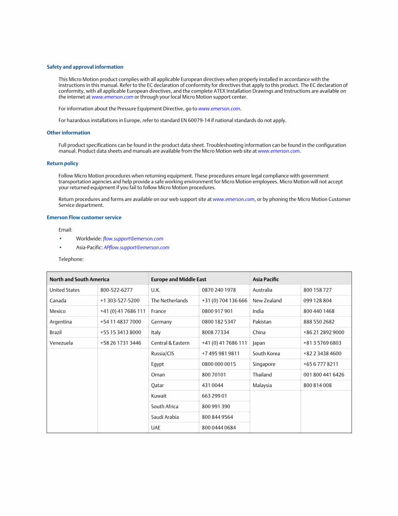
1.3 Power requirementsFollowing are the DC power requirements to operate the meter:
• 24 VDC, 0.65 W typical, 1.1 W maximum
• Minimum recommended voltage: 21.6 VDC with 1000 ft of 24 AWG (300 m of0.20 mm2) power-supply cable
• At startup, power source must provide a minimum of 0.5 A of short-term current ata minimum of 19.6 V at the power-input terminals.
Planning
2 Micro Motion Fork Density Meter
Power cable recommendations for explosion-proof/flameproof meters
Minimum wire gauge (AWG per foot or meter)Figure 1-1:
300ft 600ft 900ft 1200ft 1500ft 1800ft 2100ft 2400ft 2700ft 3000ft
B
2 1 . 6V
24 V
14
15
16
17
18
19
20
21
22
23
24
25
26
A
91.44m 182.88m 274.32m 365.76m 457.2m 548.64m 640.08m 731.52m 822.96m 914.4m
A. AWG maximumB. Distance of installation
Planning
Installation Manual 3
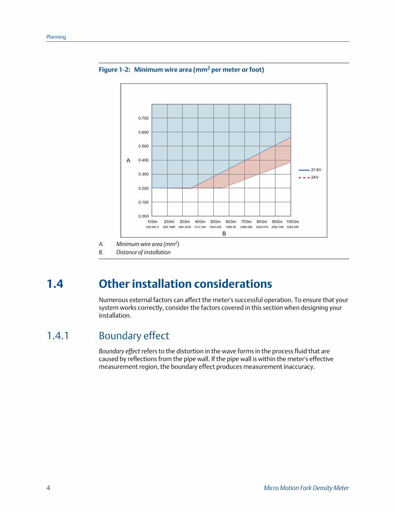
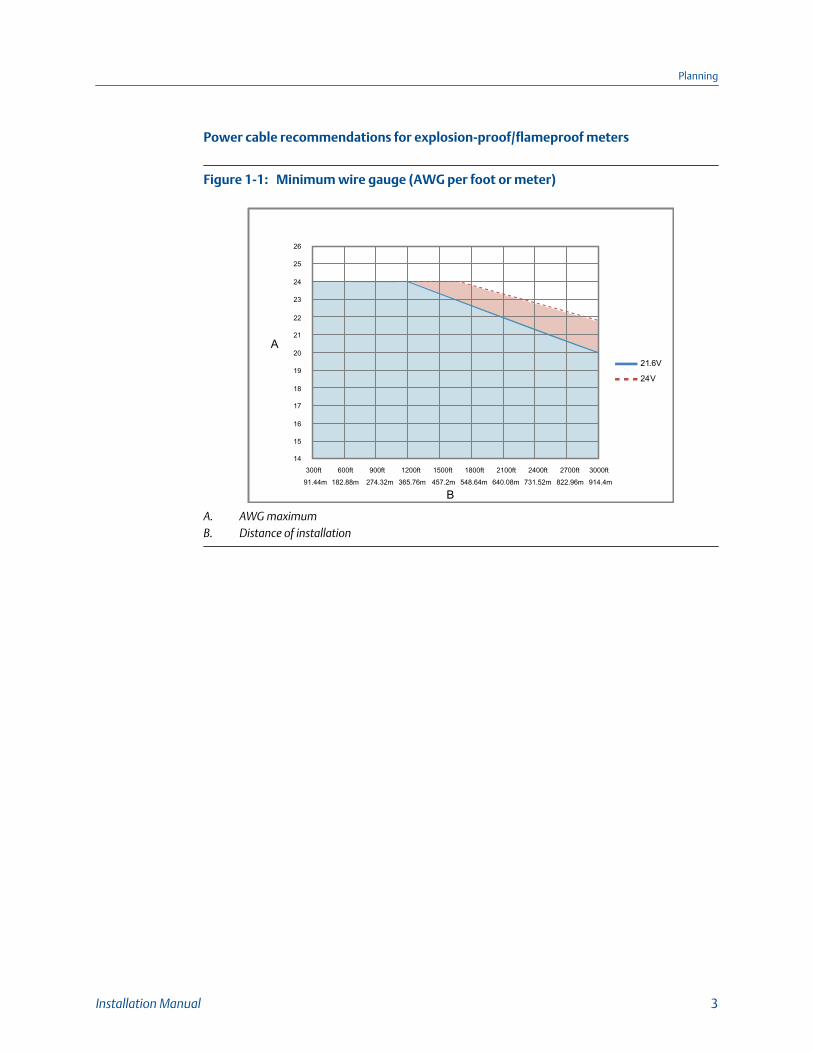
Minimum wire area (mm2 per meter or foot)Figure 1-2:
0 . 00 0
0.100
0.200
0.300
0.400
0.500
0.600
0.700
10 0m 20 0m 30 0m 40 0m 50 0m 60 0m 70 0m 80 0m 90 0m 100 0m
B
2 1 . 6V
24 V
A
328.084 ft 656.168ft 984.253ft 1312.34ft 1640.42ft 1968.5ft 2296.59ft 2624.67ft 2952.76ft 3280.84ft
A. Minimum wire area (mm2)B. Distance of installation
1.4 Other installation considerationsNumerous external factors can affect the meter's successful operation. To ensure that yoursystem works correctly, consider the factors covered in this section when designing yourinstallation.
1.4.1 Boundary effectBoundary effect refers to the distortion in the wave forms in the process fluid that arecaused by reflections from the pipe wall. If the pipe wall is within the meter's effectivemeasurement region, the boundary effect produces measurement inaccuracy.
Planning
4 Micro Motion Fork Density Meter
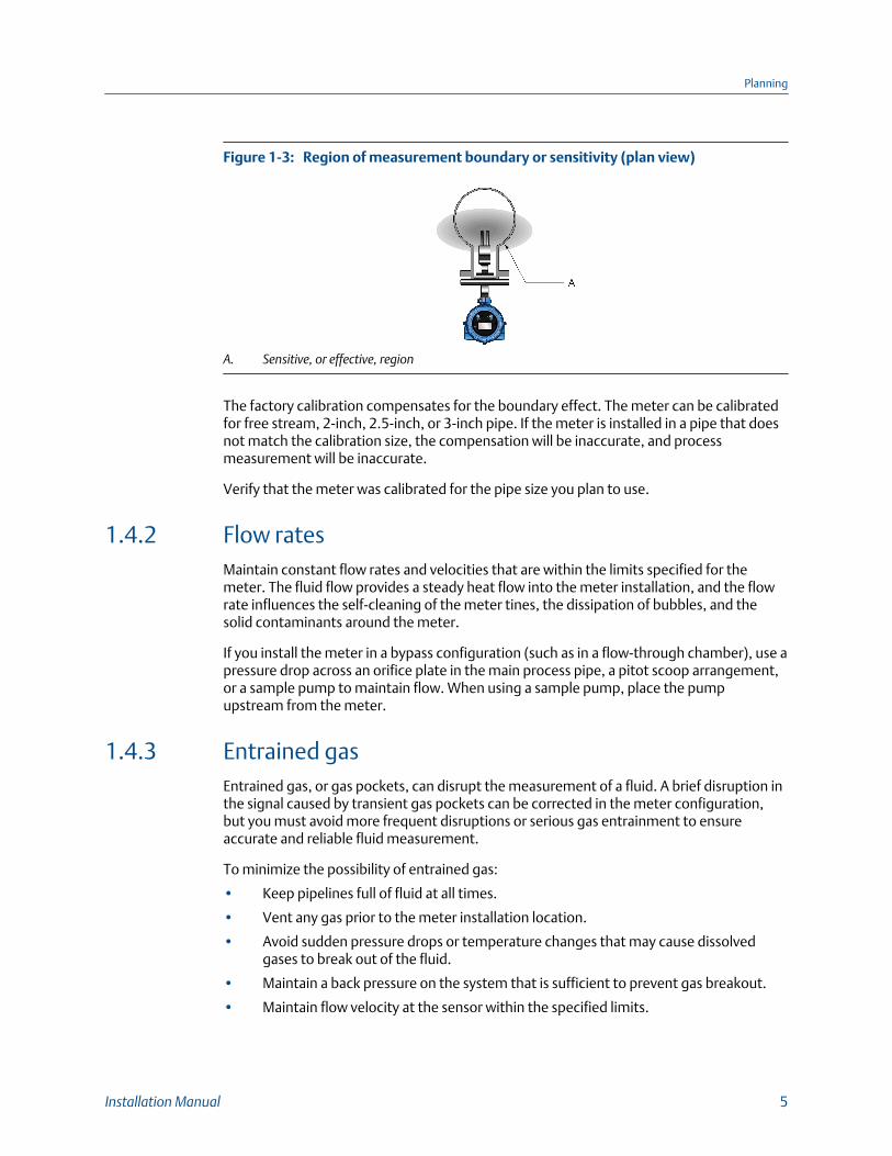
Region of measurement boundary or sensitivity (plan view)Figure 1-3:
A. Sensitive, or effective, region
The factory calibration compensates for the boundary effect. The meter can be calibratedfor free stream, 2-inch, 2.5-inch, or 3-inch pipe. If the meter is installed in a pipe that doesnot match the calibration size, the compensation will be inaccurate, and processmeasurement will be inaccurate.
Verify that the meter was calibrated for the pipe size you plan to use.
1.4.2 Flow ratesMaintain constant flow rates and velocities that are within the limits specified for themeter. The fluid flow provides a steady heat flow into the meter installation, and the flowrate influences the self-cleaning of the meter tines, the dissipation of bubbles, and thesolid contaminants around the meter.
If you install the meter in a bypass configuration (such as in a flow-through chamber), use apressure drop across an orifice plate in the main process pipe, a pitot scoop arrangement,or a sample pump to maintain flow. When using a sample pump, place the pumpupstream from the meter.
1.4.3 Entrained gasEntrained gas, or gas pockets, can disrupt the measurement of a fluid. A brief disruption inthe signal caused by transient gas pockets can be corrected in the meter configuration,but you must avoid more frequent disruptions or serious gas entrainment to ensureaccurate and reliable fluid measurement.
To minimize the possibility of entrained gas:
• Keep pipelines full of fluid at all times.
• Vent any gas prior to the meter installation location.
• Avoid sudden pressure drops or temperature changes that may cause dissolvedgases to break out of the fluid.
• Maintain a back pressure on the system that is sufficient to prevent gas breakout.
• Maintain flow velocity at the sensor within the specified limits.
Planning
Installation Manual 5
1.4.4 Slurry measurementTo ensure quality measurement when solids are present:
• Avoid sudden changes of the fluid velocity that may cause sedimentation.
• Install the meter far enough downstream from any pipework configuration that maycause centrifuging of solids (such as at a pipe bend).
• Maintain flow velocity at the meter installation that is within the specified limits.
1.4.5 Temperature gradients and insulationFor high-viscosity fluids, minimize any temperature gradients in the fluid, and in the pipingand fittings immediately upstream and downstream of the meter. Minimizingtemperature gradients reduces the effect of viscosity changes. Micro Motion recommendsusing the following guidelines to reduce the thermal effects to your meter installation:
• Always insulate the meter and surrounding pipework thoroughly.
- Avoid insulating the transmitter housing.
- Use rock wool or any equivalent heat jacket material that is at least 1 inch (25mm) thick, but preferably 2 inches (50 mm) thick.
- Enclose insulation in a sealed protective casing to prevent moisture ingress, aircirculation, and crushing of the insulation.
- For flow-through chamber installations, use the special insulation jacketprovided by Micro Motion.
• Avoid direct heat or cold on the meter or on the associated upstream ordownstream pipe work that is likely to create temperature gradients.
• If it is necessary to protect against cooling because of flow loss, you can applyelectrical-trace heating. If you use electrical-trace heating, use a thermostat thatoperates below the minimum operating temperature of the system.
1.4.6 Pressure and temperature limits for process connectionsYou must ensure that the pressure and temperature limits for the meter are notexceeded – if necessary, by the use of suitable safety accessories. Pressure andtemperature ratings for the meter connections are in accordance with the relevant flangestandard. Check the latest standards for your connections.
For the pressure and temperature limits for Zirconium 702 process connections, see Table 1-1.
Pressure/temperature ratings for Zirconium 702 process connectionsTable 1-1:
Processflangetype
Pressure and temperature ratings
100 °F (37.8 °C) 199.9 °F (93.3 °C) 299.8 °F (148.8 °C) 392 °F (200 °C)
2” ANSI150
226.3 psi (15.6 bar) 197.3 psi (13.6 bar) 159.5 psi (11.0 bar) 110.2 psi (7.6 bar)
Planning
6 Micro Motion Fork Density Meter
Pressure/temperature ratings for Zirconium 702 process connections(continued)Table 1-1:
Processflangetype
Pressure and temperature ratings
100 °F (37.8 °C) 199.9 °F (93.3 °C) 299.8 °F (148.8 °C) 392 °F (200 °C)
2” ANSI300
588.9psi (40.6 bar) 513.4 psi (35.4 bar) 417.7 psi (28.8 bar) 336.5 psi (23.2 bar)
DN50PN16
229.2 psi (15.8 bar) 175.5 psi (12.1 bar) 137.8 psi (9.5 bar) 107.3 psi (7.4 bar)
DN50PN40
571.5 psi (39.4 bar) 439.5 (30.3 bar) 342.3 psi (23.6 bar) 266.9 psi (18.4 bar)
1.5 Recommended installations for short-stemmetersMicro Motion recommends three standard installations for the short-stem meter toalleviate any need for onsite calibration. All meters are factory calibrated for these types ofinstallations and take into consideration the potential boundary effect of each installation.
Free stream applications
Flow rate 0.3 to 0.5 m/s at the meter
Viscosity Up to 20,000 cP
Temperature • –58 °F to 392 °F (–50 °C to 200 °C)• -40 °F to 392 °F (-40 °C to 200 °C) in hazardous areas
Main flow pipe size • Horizontal pipe: minimum diameter, 4 inch (100 mm)• Vertical pipe: minimum diameter, 6 inch (150 mm)
Advantages • Simple installation in large bore pipes• Ideal for clean fluids and non-waxing oils• Suitable for line density measurement and simple referrals
Recommendations Do not use with:• Low or unstable flow rates• For small bore pipes
T-piece applications
Flow rate 0.5 to 3 m/s at main pipe wall
By increasing the insertion depth of the tines into the T-piece,the flow velocity can be increased to 5 m/s for clean fluids. Forslurry applications, the maximum flow velocity should be nogreater than 4m/s.
Planning
Installation Manual 7
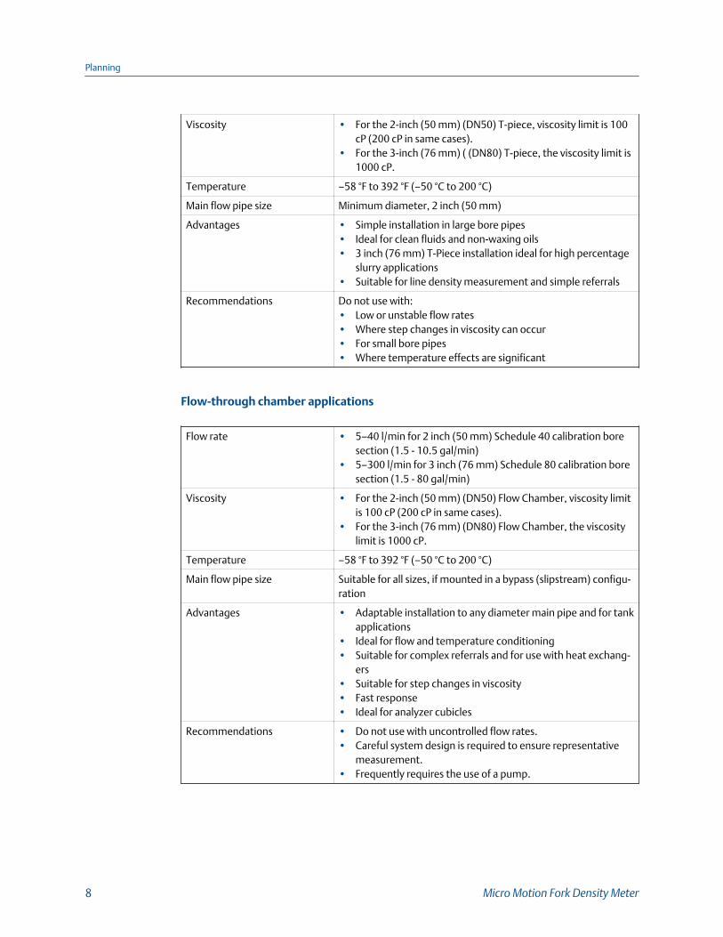
Viscosity • For the 2-inch (50 mm) (DN50) T-piece, viscosity limit is 100cP (200 cP in same cases).
• For the 3-inch (76 mm) ( (DN80) T-piece, the viscosity limit is1000 cP.
Temperature –58 °F to 392 °F (–50 °C to 200 °C)
Main flow pipe size Minimum diameter, 2 inch (50 mm)
Advantages • Simple installation in large bore pipes• Ideal for clean fluids and non-waxing oils• 3 inch (76 mm) T-Piece installation ideal for high percentage
slurry applications• Suitable for line density measurement and simple referrals
Recommendations Do not use with:• Low or unstable flow rates• Where step changes in viscosity can occur• For small bore pipes• Where temperature effects are significant
Flow-through chamber applications
Flow rate • 5–40 l/min for 2 inch (50 mm) Schedule 40 calibration boresection (1.5 - 10.5 gal/min)
• 5–300 l/min for 3 inch (76 mm) Schedule 80 calibration boresection (1.5 - 80 gal/min)
Viscosity • For the 2-inch (50 mm) (DN50) Flow Chamber, viscosity limitis 100 cP (200 cP in same cases).
• For the 3-inch (76 mm) (DN80) Flow Chamber, the viscositylimit is 1000 cP.
Temperature –58 °F to 392 °F (–50 °C to 200 °C)
Main flow pipe size Suitable for all sizes, if mounted in a bypass (slipstream) configu-ration
Advantages • Adaptable installation to any diameter main pipe and for tankapplications
• Ideal for flow and temperature conditioning• Suitable for complex referrals and for use with heat exchang-
ers• Suitable for step changes in viscosity• Fast response• Ideal for analyzer cubicles
Recommendations • Do not use with uncontrolled flow rates.• Careful system design is required to ensure representative
measurement.• Frequently requires the use of a pump.
Planning
8 Micro Motion Fork Density Meter

1.6 Perform a pre-installation meter check1. Remove the meter from the box.
CAUTION!
Handle the meter with care. Follow all corporate, local, and national safety regulationsfor lifting and moving the meter.
2. Visually inspect the meter for any physical damage.
If you notice any physical damage to the meter, immediately contact Micro MotionCustomer Support at [email protected].
3. Position and secure the meter in a vertical position with the flow arrow pointingupward.
4. Connect the power wiring, and power up the meter.
Remove the back transmitter housing cover to access the PWR terminals.
Power supply wiring terminalsFigure 1-4:
A. 24 VDC
5. Perform a Known Density Verification (KDV) check.
Use the Known Density Verification procedure to match the current metercalibration with the factory calibration. If the meter passes the test, then it has notdrifted or changed during shipment.
For more information on performing a KDV check, see the configuration and usemanual that shipped with the product.
Planning
Installation Manual 9
2 MountingTopics covered in this chapter:
• Free stream applications
• T-piece applications
• Mount with a flow-through chamber
• Mount in an open tank (long-stem meter)
• Mount in a closed tank (long-stem meter)
• Attach the PFA ring and circlip
• Rotate the electronics on the meter (optional)
• Rotate the display on the transmitter (optional)
If the meter's flow velocity is:
• Below 0.3 to 0.5 m/s, install the meter as a free-stream application.
• Above 0.3 to 0.5 m/s, install the meter as either a T-piece or flow chamberapplication. As an alternative, if the pipework can be expanded to reduce the flowvelocity to between 0.3 to 0.5 m/s, install a free stream application.
2.1 Free stream applications
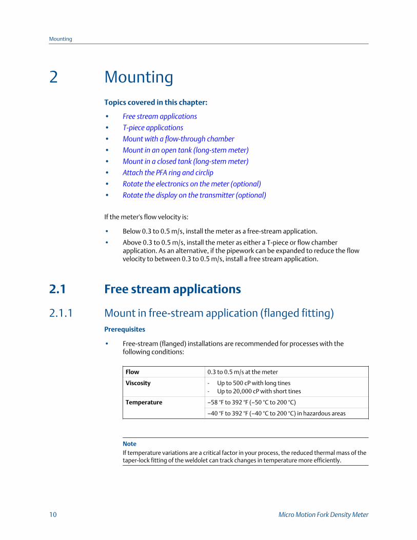
2.1.1 Mount in free-stream application (flanged fitting)Prerequisites
• Free-stream (flanged) installations are recommended for processes with thefollowing conditions:
Flow 0.3 to 0.5 m/s at the meter
Viscosity - Up to 500 cP with long tines- Up to 20,000 cP with short tines
Temperature –58 °F to 392 °F (–50 °C to 200 °C)
–40 °F to 392 °F (–40 °C to 200 °C) in hazardous areas
NoteIf temperature variations are a critical factor in your process, the reduced thermal mass of thetaper-lock fitting of the weldolet can track changes in temperature more efficiently.
Mounting
10 Micro Motion Fork Density Meter
• Before fitting the weldolet, you must bore a 2.1 in (52.5 mm) diameter opening inthe pipeline to accept the meter. You must weld the weldolet to the pipelineconcentrically with the pre-bored hole.
Procedure
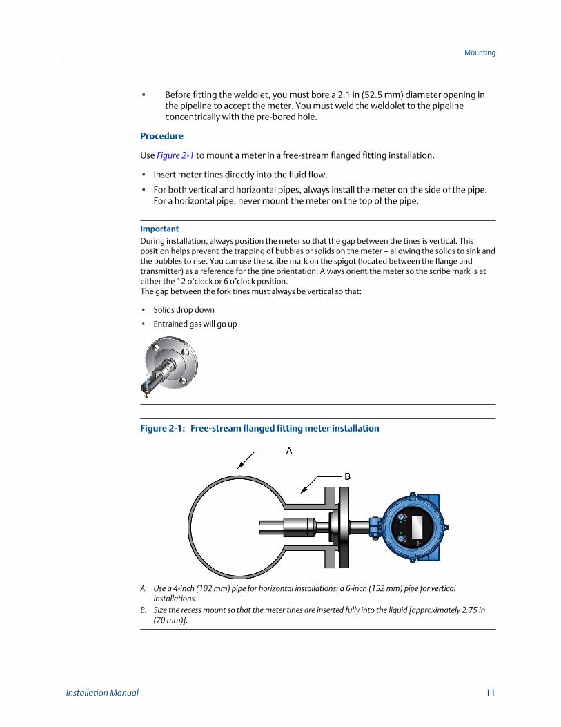
Use Figure 2-1 to mount a meter in a free-stream flanged fitting installation.
• Insert meter tines directly into the fluid flow.
• For both vertical and horizontal pipes, always install the meter on the side of the pipe.For a horizontal pipe, never mount the meter on the top of the pipe.
ImportantDuring installation, always position the meter so that the gap between the tines is vertical. Thisposition helps prevent the trapping of bubbles or solids on the meter – allowing the solids to sink andthe bubbles to rise. You can use the scribe mark on the spigot (located between the flange andtransmitter) as a reference for the tine orientation. Always orient the meter so the scribe mark is ateither the 12 o’clock or 6 o’clock position.The gap between the fork tines must always be vertical so that:
• Solids drop down
• Entrained gas will go up
Free-stream flanged fitting meter installationFigure 2-1:
A. Use a 4-inch (102 mm) pipe for horizontal installations; a 6-inch (152 mm) pipe for verticalinstallations.
B. Size the recess mount so that the meter tines are inserted fully into the liquid [approximately 2.75 in(70 mm)].
Mounting
Installation Manual 11
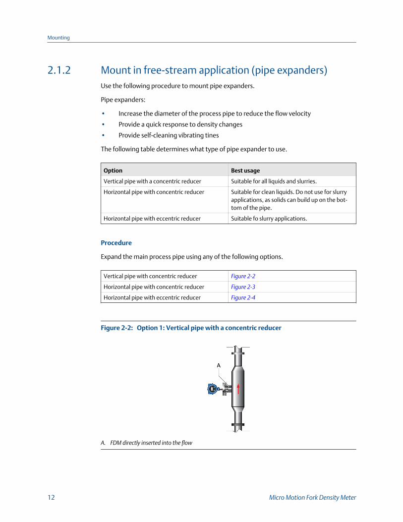
2.1.2 Mount in free-stream application (pipe expanders)Use the following procedure to mount pipe expanders.
Pipe expanders:
• Increase the diameter of the process pipe to reduce the flow velocity
• Provide a quick response to density changes
• Provide self-cleaning vibrating tines
The following table determines what type of pipe expander to use.
Option Best usage
Vertical pipe with a concentric reducer Suitable for all liquids and slurries.
Horizontal pipe with concentric reducer Suitable for clean liquids. Do not use for slurryapplications, as solids can build up on the bot-tom of the pipe.
Horizontal pipe with eccentric reducer Suitable fo slurry applications.
Procedure
Expand the main process pipe using any of the following options.
Vertical pipe with concentric reducer Figure 2-2
Horizontal pipe with concentric reducer Figure 2-3
Horizontal pipe with eccentric reducer Figure 2-4
Option 1: Vertical pipe with a concentric reducerFigure 2-2:
A. FDM directly inserted into the flow
Mounting
12 Micro Motion Fork Density Meter
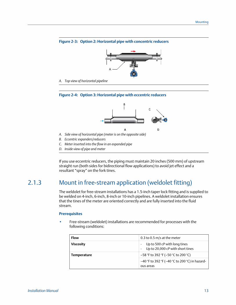
Option 2: Horizontal pipe with concentric reducersFigure 2-3:
A. Top view of horizontal pipeline
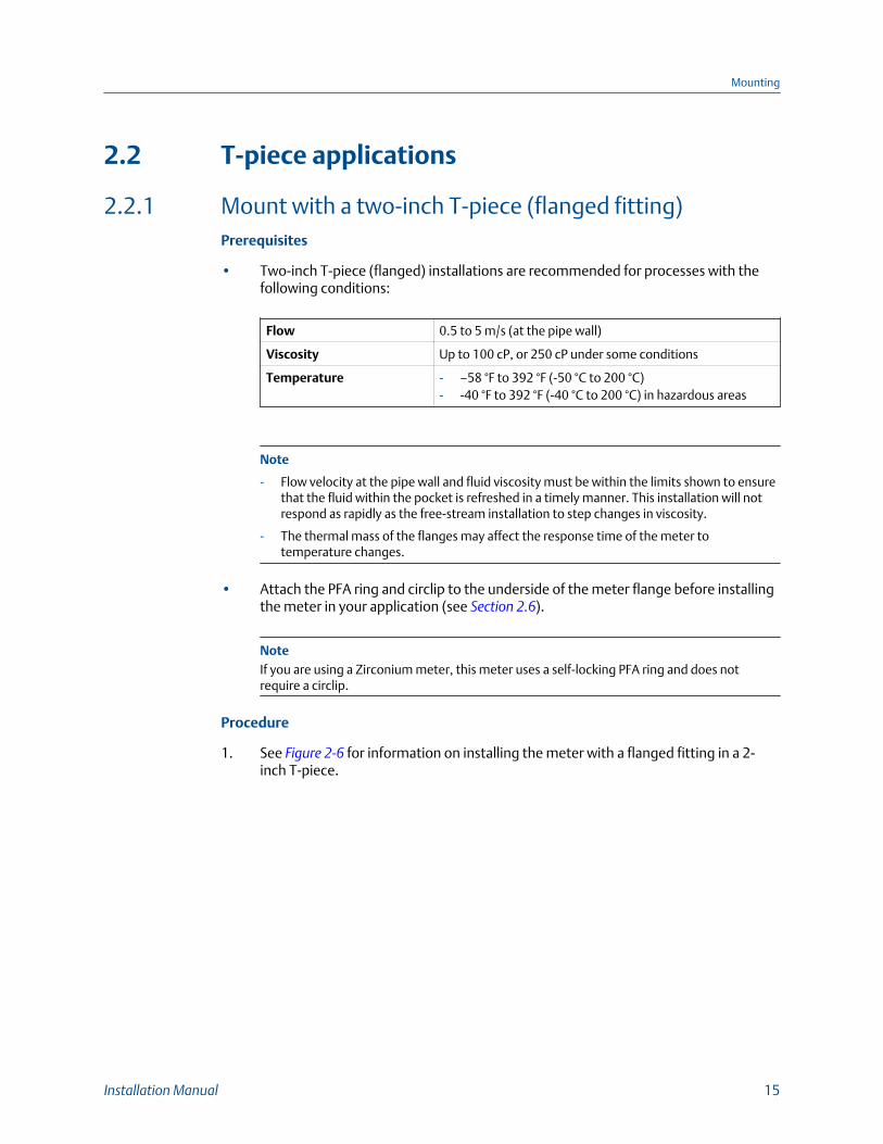
Option 3: Horizontal pipe with eccentric reducersFigure 2-4:
A. Side view of horizontal pipe (meter is on the opposite side)B. Eccentric expanders/reducersC. Meter inserted into the flow in an expanded pipeD. Inside view of pipe and meter
If you use eccentric reducers, the piping must maintain 20 inches (500 mm) of upstreamstraight run (both sides for bidirectional flow applications) to avoid jet effect and aresultant “spray” on the fork tines.
2.1.3 Mount in free-stream application (weldolet fitting)The weldolet for free-stream installations has a 1.5-inch taper lock fitting and is supplied tobe welded on 4-inch, 6-inch, 8-inch or 10-inch pipelines. A weldolet installation ensuresthat the tines of the meter are oriented correctly and are fully inserted into the fluidstream.
Prerequisites
• Free-stream (weldolet) installations are recommended for processes with thefollowing conditions:
Flow 0.3 to 0.5 m/s at the meter
Viscosity - Up to 500 cP with long tines- Up to 20,000 cP with short tines
Temperature –58 °F to 392 °F (–50 °C to 200 °C)
–40 °F to 392 °F (–40 °C to 200 °C) in hazard-ous areas
Mounting
Installation Manual 13

NoteIf temperature variations are a critical factor in your process, the reduced thermal mass of thetaper-lock fitting of the weldolet can track changes in temperature more efficiently.
• Before fitting the weldolet, you must bore a 2.1 in (52.5 mm) diameter opening inthe pipeline to accept the meter. You must weld the weldolet to the pipelineconcentrically with the pre-bored hole.
Procedure
See Figure 2-5 for information on installing the meter (with a weldolet fitting) in a free-stream application.
• Insert meter tines directly into the fluid flow.
• For both vertical and horizontal pipes, always install the meter on the side of the pipe.For a horizontal pipe, never mount the meter on the top of the pipe.
ImportantDuring installation, always position the meter so that the gap between the tines is vertical. Thisposition helps prevent the trapping of bubbles or solids on the meter – allowing the solids to sink andthe bubbles to rise. You can use the scribe mark on the spigot (located between the flange andtransmitter) as a reference for the tine orientation. Always orient the meter so the scribe mark is ateither the 12 o’clock or 6 o’clock position.The gap between the fork tines must always be vertical so that:
• Solids drop down
• Entrained gas will go up
Free-stream (weldolet fitting) meter installationFigure 2-5:
A. 4-inch pipe for horizontal installations; 6-inch (152 mm) pipe for vertical installationsB. 2.1 in (52.5 mm) meter opening in pipelineC. WeldD. Free-stream weldolet (purchased to fit pipe diameter)
Mounting
14 Micro Motion Fork Density Meter
2.2 T-piece applications
2.2.1 Mount with a two-inch T-piece (flanged fitting)Prerequisites
• Two-inch T-piece (flanged) installations are recommended for processes with thefollowing conditions:
Flow 0.5 to 5 m/s (at the pipe wall)
Viscosity Up to 100 cP, or 250 cP under some conditions
Temperature - –58 °F to 392 °F (-50 °C to 200 °C)- -40 °F to 392 °F (-40 °C to 200 °C) in hazardous areas
Note
- Flow velocity at the pipe wall and fluid viscosity must be within the limits shown to ensurethat the fluid within the pocket is refreshed in a timely manner. This installation will notrespond as rapidly as the free-stream installation to step changes in viscosity.
- The thermal mass of the flanges may affect the response time of the meter totemperature changes.
• Attach the PFA ring and circlip to the underside of the meter flange before installingthe meter in your application (see Section 2.6).
NoteIf you are using a Zirconium meter, this meter uses a self-locking PFA ring and does notrequire a circlip.
Procedure
1. See Figure 2-6 for information on installing the meter with a flanged fitting in a 2-inch T-piece.
Mounting
Installation Manual 15
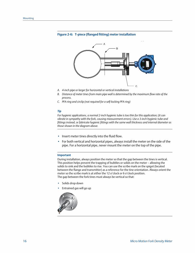
T-piece (flanged fitting) meter installationFigure 2-6:
A. 4-inch pipe or larger for horizontal or vertical installationsB. Distance of meter tines from main pipe wall is determined by the maximum flow rate of the
process.C. PFA ring and circlip (not required for a self-locking PFA ring)
TipFor hygienic applications, a normal 2-inch hygienic tube is too thin for this application; (it canvibrate in sympathy with the fork, causing measurement errors). Use a 3-inch hygienic tube andfittings instead, or fabricate hygienic fittings with the same wall thickness and internal diameter asthose shown in the diagram above.
• Insert meter tines directly into the fluid flow.
• For both vertical and horizontal pipes, always install the meter on the side of thepipe. For a horizontal pipe, never mount the meter on the top of the pipe.
ImportantDuring installation, always position the meter so that the gap between the tines is vertical.This position helps prevent the trapping of bubbles or solids on the meter – allowing thesolids to sink and the bubbles to rise. You can use the scribe mark on the spigot (locatedbetween the flange and transmitter) as a reference for the tine orientation. Always orient themeter so the scribe mark is at either the 12 o’clock or 6 o’clock position.The gap between the fork tines must always be vertical so that:
• Solids drop down
• Entrained gas will go up
Mounting
16 Micro Motion Fork Density Meter
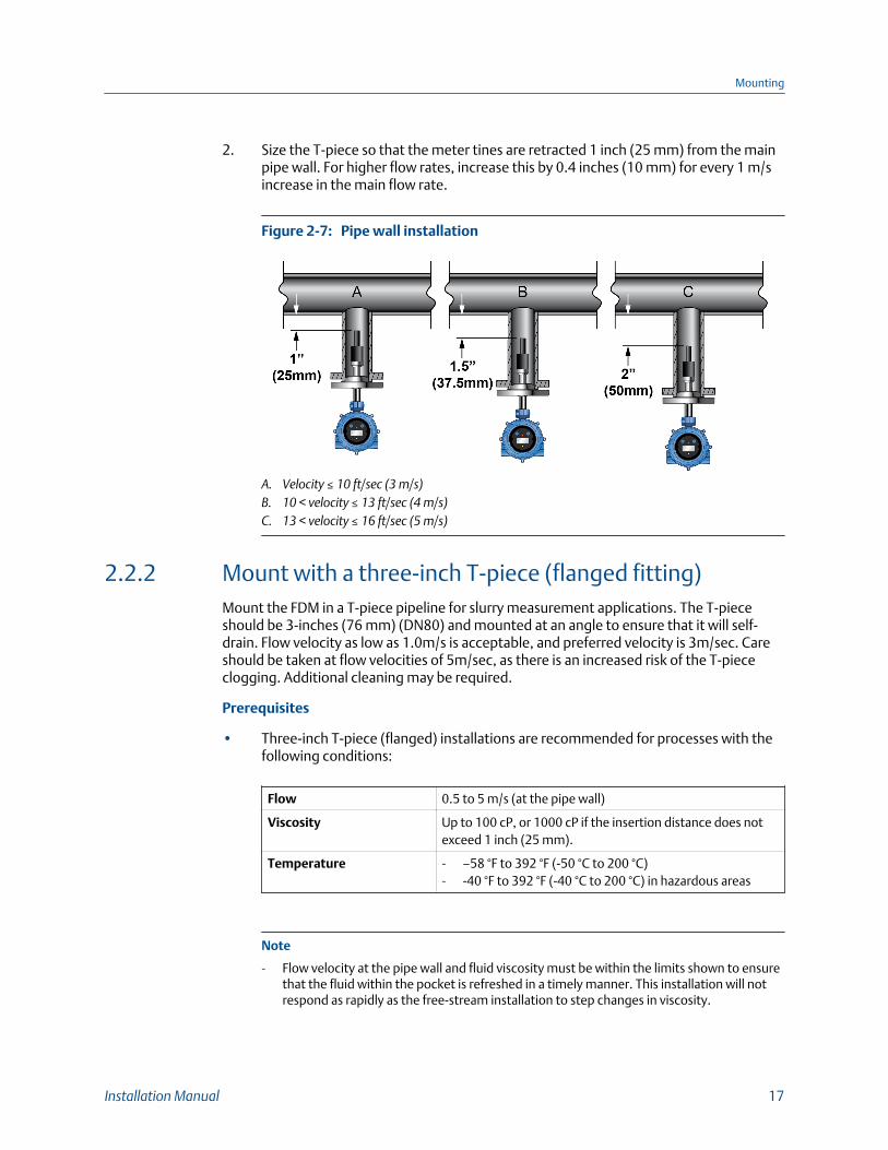
2. Size the T-piece so that the meter tines are retracted 1 inch (25 mm) from the mainpipe wall. For higher flow rates, increase this by 0.4 inches (10 mm) for every 1 m/sincrease in the main flow rate.
Pipe wall installationFigure 2-7:
A. Velocity ≤ 10 ft/sec (3 m/s)B. 10 < velocity ≤ 13 ft/sec (4 m/s)C. 13 < velocity ≤ 16 ft/sec (5 m/s)
2.2.2 Mount with a three-inch T-piece (flanged fitting)Mount the FDM in a T-piece pipeline for slurry measurement applications. The T-pieceshould be 3-inches (76 mm) (DN80) and mounted at an angle to ensure that it will self-drain. Flow velocity as low as 1.0m/s is acceptable, and preferred velocity is 3m/sec. Careshould be taken at flow velocities of 5m/sec, as there is an increased risk of the T-piececlogging. Additional cleaning may be required.
Prerequisites
• Three-inch T-piece (flanged) installations are recommended for processes with thefollowing conditions:
Flow 0.5 to 5 m/s (at the pipe wall)
Viscosity Up to 100 cP, or 1000 cP if the insertion distance does notexceed 1 inch (25 mm).
Temperature - –58 °F to 392 °F (-50 °C to 200 °C)- -40 °F to 392 °F (-40 °C to 200 °C) in hazardous areas
Note
- Flow velocity at the pipe wall and fluid viscosity must be within the limits shown to ensurethat the fluid within the pocket is refreshed in a timely manner. This installation will notrespond as rapidly as the free-stream installation to step changes in viscosity.
Mounting
Installation Manual 17
- The thermal mass of the flanges may affect the response time of the meter totemperature changes.
• Attach the PFA ring and circlip to the underside of the meter flange before installingthe meter in your application (see Section 2.6).
NoteIf you are using a Zirconium meter, this meter uses a self-locking PFA ring and does notrequire a circlip.
Procedure
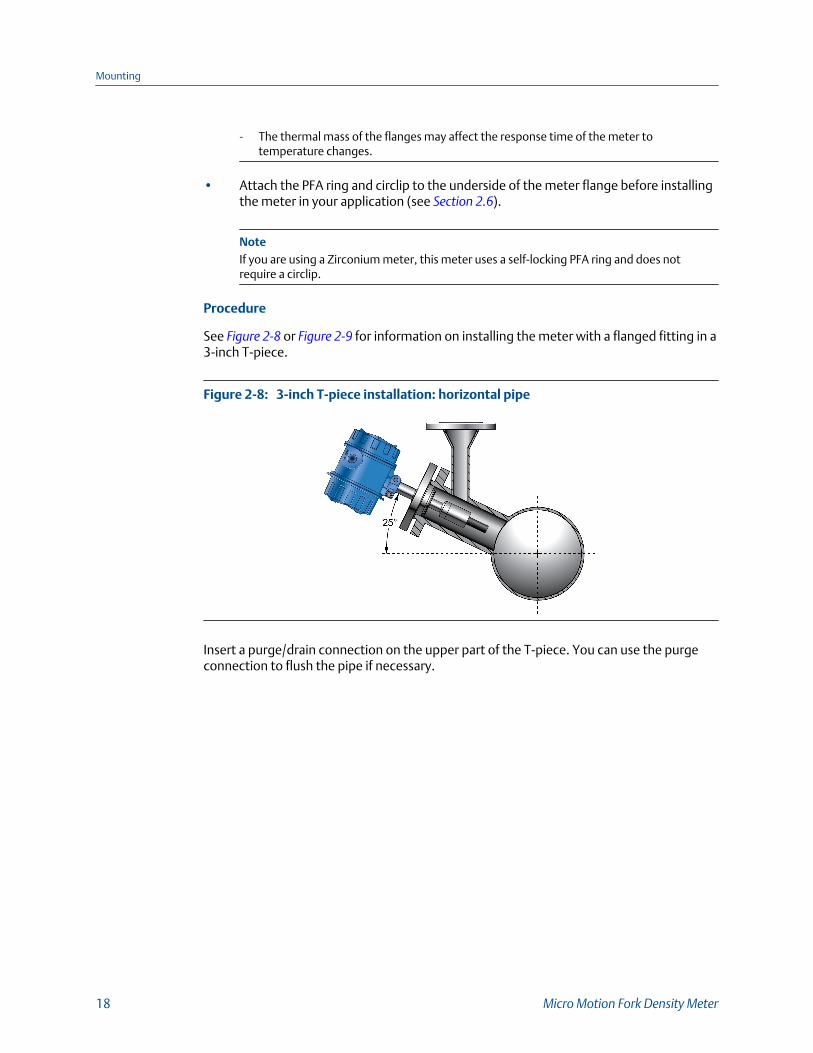
See Figure 2-8 or Figure 2-9 for information on installing the meter with a flanged fitting in a3-inch T-piece.
3-inch T-piece installation: horizontal pipeFigure 2-8:
Insert a purge/drain connection on the upper part of the T-piece. You can use the purgeconnection to flush the pipe if necessary.
Mounting
18 Micro Motion Fork Density Meter
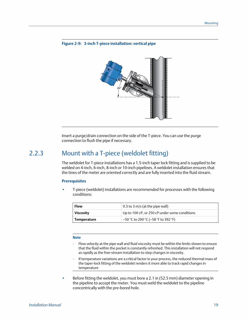
3-inch T-piece installation: vertical pipeFigure 2-9:
Insert a purge/drain connection on the side of the T-piece. You can use the purgeconnection to flush the pipe if necessary.
2.2.3 Mount with a T-piece (weldolet fitting)The weldolet for T-piece installations has a 1.5-inch taper lock fitting and is supplied to bewelded on 4-inch, 6-inch, 8-inch or 10-inch pipelines. A weldolet installation ensures thatthe tines of the meter are oriented correctly and are fully inserted into the fluid stream.
Prerequisites
• T-piece (weldolet) installations are recommended for processes with the followingconditions:
Flow 0.5 to 3 m/s (at the pipe wall)
Viscosity Up to 100 cP, or 250 cP under some conditions
Temperature –50 °C to 200 °C (–58 °F to 392 °F)
Note
- Flow velocity at the pipe wall and fluid viscosity must be within the limits shown to ensurethat the fluid within the pocket is constantly refreshed. This installation will not respondas rapidly as the free-stream installation to step changes in viscosity.
- If temperature variations are a critical factor in your process, the reduced thermal mass ofthe taper-lock fitting of the weldolet renders it more able to track rapid changes intemperature
• Before fitting the weldolet, you must bore a 2.1 in (52.5 mm) diameter opening inthe pipeline to accept the meter. You must weld the weldolet to the pipelineconcentrically with the pre-bored hole.
Mounting
Installation Manual 19

Procedure
See Figure 2-5 for information on installing the meter (with a weldolet fitting) in a T-piece.
Size the T-piece so that the meter tines are retracted 1 in (25 mm) from the main pipe wall.For higher flow rates, increase this by 10 mm for every 1 m/s increase in the main flow rate.
ImportantDuring installation, always position the meter so that the gap between the tines is vertical. Thisposition helps prevent the trapping of bubbles or solids on the meter – allowing the solids to sink andthe bubbles to rise. You can use the scribe mark on the spigot (located between the flange andtransmitter) as a reference for the tine orientation. Always orient the meter so the scribe mark is ateither the 12 o’clock or 6 o’clock position.The gap between the fork tines must always be vertical so that:
• Solids drop down
• Entrained gas will go up
T-piece (weldolet fitting) meter installationFigure 2-10:
A. 4-inch pipe or larger for horizontal or vertical installationsB. 2.1 in (52.5 mm) meter opening in pipelineC. Distance of meter tines from main pipe wall is determined by the maximum flow rate of the processD. Weldolet (purchased to fit pipe diameter)
2.3 Mount with a flow-through chamberFlow-through chambers are manufactured by Micro Motion, and are available with eitherof the following:
• Welded ends or compression fittings that connect into the process pipelines
• 1- inch, 2-inch, or 3-inch inlet and outlet pipes
Mounting
20 Micro Motion Fork Density Meter
ImportantDo not alter the length of the inlet and outlet pipes. Pipe alterations can adversely affect the fittingtemperature response and stability.
Prerequisites
Verify the following conditions:
Flow • 5–40 l/min for 2-inch Schedule 40 calibration bore section (1.5 - 10.5gal/min)
• 5–300 l/min for 3-inch Schedule 80 calibration bore section (1.5 - 80gal/min)
Viscosity Up to 1000 cP
Temperature –50 °C to 200 °C (–58 °F to 392 °F)
–40 °C to 200 °C (–40 °F to 392 °F) in hazardous areas
Pressure 70 bar @ 204 °C, subject to process connections
Important
• To ensure that the fluid within the pocket is refreshed in a timely manner, verify that flowvelocity at the pipe wall and fluid viscosity are within the limits described in this table.
• The thermal mass of the flanges may affect the response time of the meter to temperaturechanges.
Procedure
See Figure 2-11 for an example installation of a meter in a flow-through chamber.
Mounting
Installation Manual 21

Flow-through chamber meter installationFigure 2-11:
A. Optional temperature port
Note• This flow-through chamber is a direct-insertion type chamber that does not have a thermowell, and
uses a ¾-inch Swagelok connection.• The three compression fittings on the flow pockets (½-inch drain, ¾-inch temperature probe, and 1-½-
inch mounting nut for the meter) are rated to above the working pressure of the flow pocket. Thefittings may be Swagelok or Parker.
2.4 Mount in an open tank (long-stem meter)
CAUTION!
Only the safe area version of the long-stem meter can be mounted in an open tank.
Prerequisites
Verify the following conditions:
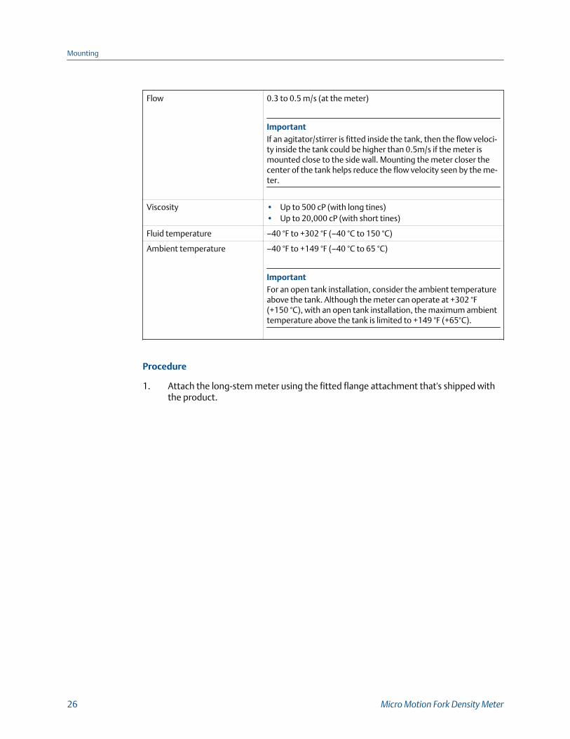
Flow 0.3 to 0.5 m/s (at the meter)
ImportantIf an agitator/stirrer is fitted inside the tank, then the flow veloci-ty inside the tank could be higher than 0.5m/s if the meter ismounted close to the side wall. Mounting the meter closer thecenter of the tank helps reduce the flow velocity seen by the me-ter.
Viscosity • Up to 500 cP (with long tines)• Up to 20,000 cP (with short tines)
Fluid temperature –40 °F to +302 °F (–40 °C to 150 °C)
Mounting
22 Micro Motion Fork Density Meter
Ambient temperature –40 °F to +149 °F (–40 °C to 65 °C)
ImportantFor an open tank installation, consider the ambient temperatureabove the tank. Although the meter can operate at +302 °F(+150 °C), with an open tank installation, the maximum ambienttemperature above the tank is limited to +149 °F (+65°C).
Procedure
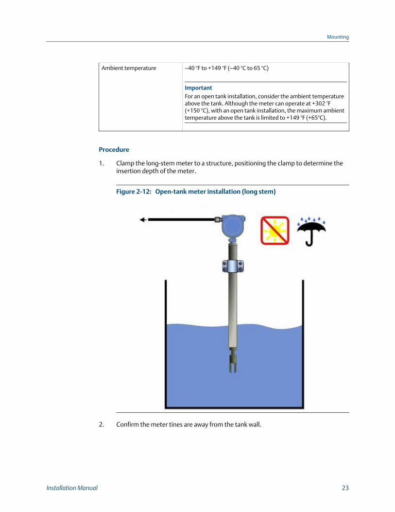
1. Clamp the long-stem meter to a structure, positioning the clamp to determine theinsertion depth of the meter.
Open-tank meter installation (long stem)Figure 2-12:
2. Confirm the meter tines are away from the tank wall.
Mounting
Installation Manual 23
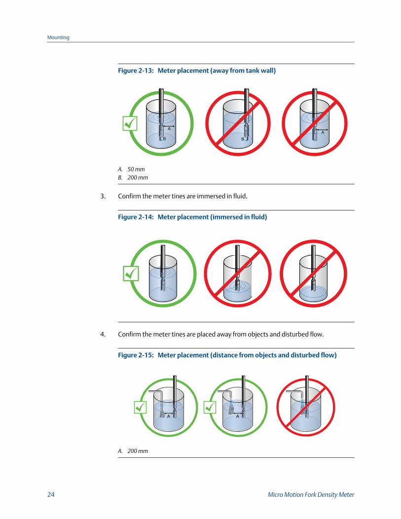
Meter placement (away from tank wall)Figure 2-13:
B
AA
B
A. 50 mmB. 200 mm
3. Confirm the meter tines are immersed in fluid.
Meter placement (immersed in fluid)Figure 2-14:
4. Confirm the meter tines are placed away from objects and disturbed flow.
Meter placement (distance from objects and disturbed flow)Figure 2-15:
A A
A. 200 mm
Mounting
24 Micro Motion Fork Density Meter

5. If flow exists, confirm the meter tines are aligned so that the flow is directed towardsor through the gap between the tines.
Meter placement (flow direction through tine gap)Figure 2-16:
6. Confirm the meter tines are kept away from deposit buildup.
Meter placement (away from deposit buildup)Figure 2-17:
2.5 Mount in a closed tank (long-stem meter)Prerequisites
Verify the following conditions:
Mounting
Installation Manual 25
Flow 0.3 to 0.5 m/s (at the meter)
ImportantIf an agitator/stirrer is fitted inside the tank, then the flow veloci-ty inside the tank could be higher than 0.5m/s if the meter ismounted close to the side wall. Mounting the meter closer thecenter of the tank helps reduce the flow velocity seen by the me-ter.
Viscosity • Up to 500 cP (with long tines)• Up to 20,000 cP (with short tines)
Fluid temperature –40 °F to +302 °F (–40 °C to 150 °C)
Ambient temperature –40 °F to +149 °F (–40 °C to 65 °C)
ImportantFor an open tank installation, consider the ambient temperatureabove the tank. Although the meter can operate at +302 °F(+150 °C), with an open tank installation, the maximum ambienttemperature above the tank is limited to +149 °F (+65°C).
Procedure
1. Attach the long-stem meter using the fitted flange attachment that's shipped withthe product.
Mounting
26 Micro Motion Fork Density Meter

Closed-tank installation (fitted flange attachment)Figure 2-18:
2. (Optional) To vary the insertion depth of the meter, mount the meter on a standoffsection that attaches to the flange (not provided).
Mounting
Installation Manual 27
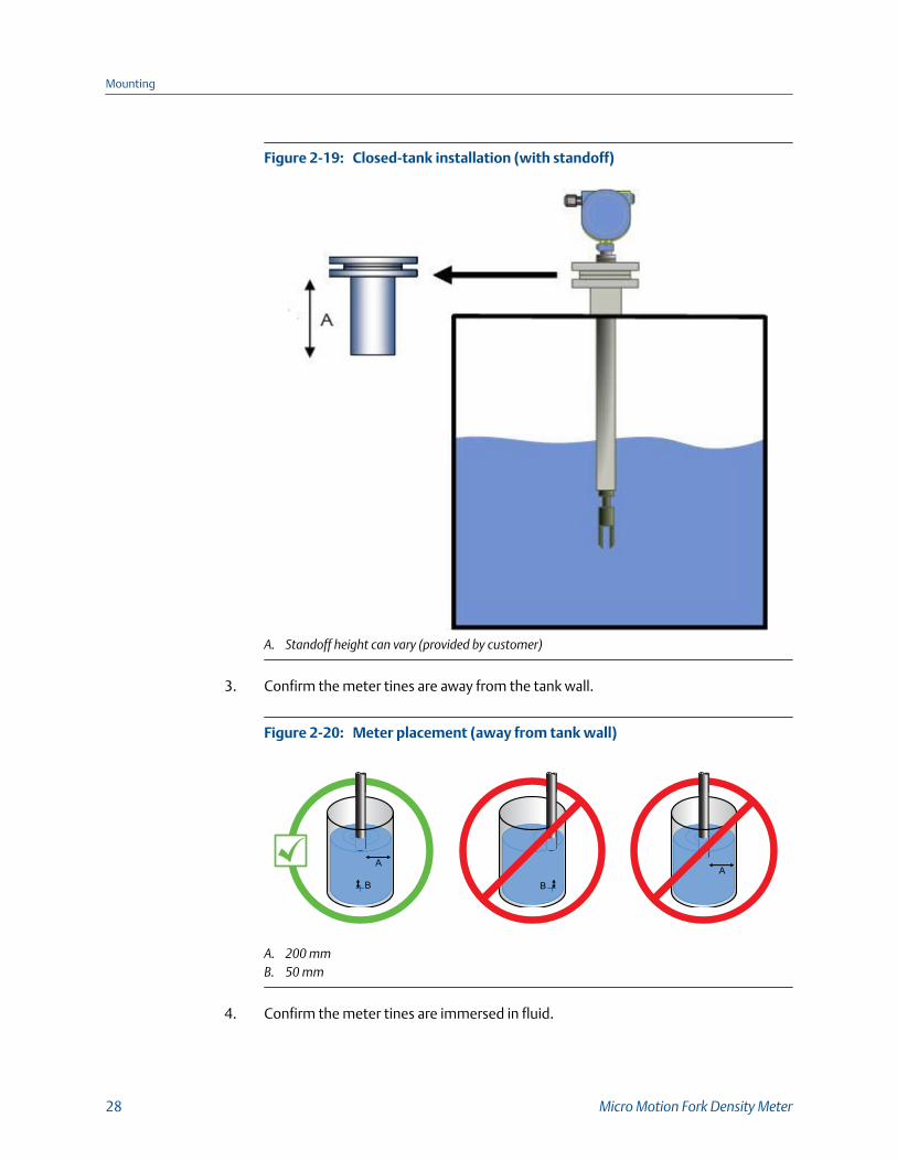
Closed-tank installation (with standoff)Figure 2-19:
A. Standoff height can vary (provided by customer)
3. Confirm the meter tines are away from the tank wall.
Meter placement (away from tank wall)Figure 2-20:
B
AA
B
A. 200 mmB. 50 mm
4. Confirm the meter tines are immersed in fluid.
Mounting
28 Micro Motion Fork Density Meter
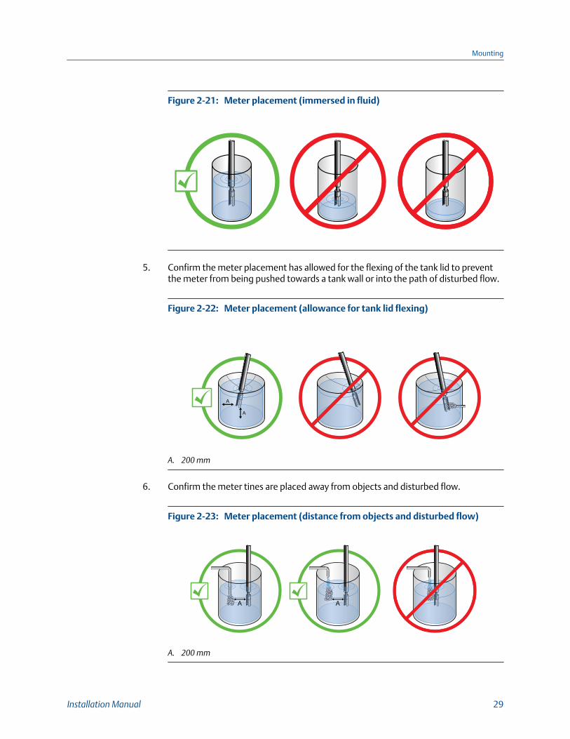
Meter placement (immersed in fluid)Figure 2-21:
5. Confirm the meter placement has allowed for the flexing of the tank lid to preventthe meter from being pushed towards a tank wall or into the path of disturbed flow.
Meter placement (allowance for tank lid flexing)Figure 2-22:
A
A
A. 200 mm
6. Confirm the meter tines are placed away from objects and disturbed flow.
Meter placement (distance from objects and disturbed flow)Figure 2-23:
A A
A. 200 mm
Mounting
Installation Manual 29

7. If flow exists, confirm the meter tines are aligned so that the flow is directed towardsor through the gap between the tines.
Meter placement (flow direction through tine gap)Figure 2-24:
8. Confirm the meter tines are kept away from deposit buildup.
Meter placement (away from deposit buildup)Figure 2-25:
2.6 Attach the PFA ring and circlipYou attach the PFA ring (and circlip) around the boss on the underside of the meter flangeto center the meter tines within a 2-inch Schedule 40 or 80 pipe. The circlip holds the ringin place.
Mounting
30 Micro Motion Fork Density Meter
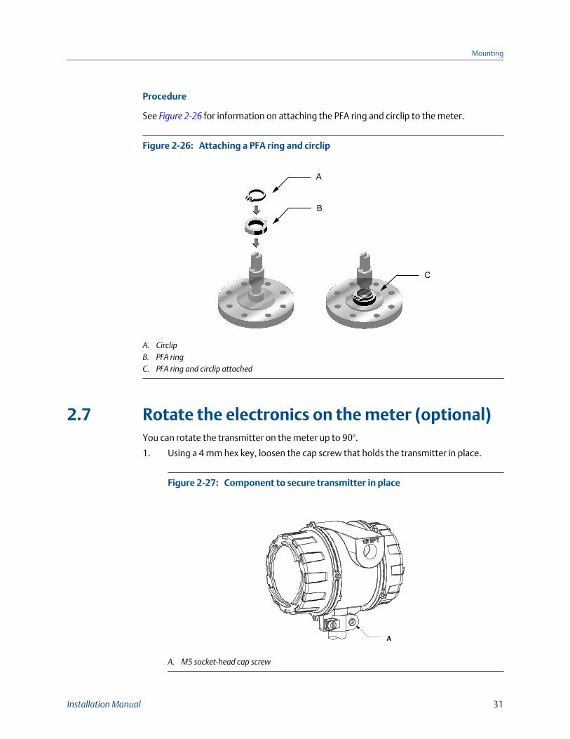
Procedure
See Figure 2-26 for information on attaching the PFA ring and circlip to the meter.
Attaching a PFA ring and circlipFigure 2-26:
B
A
C
A. CirclipB. PFA ringC. PFA ring and circlip attached
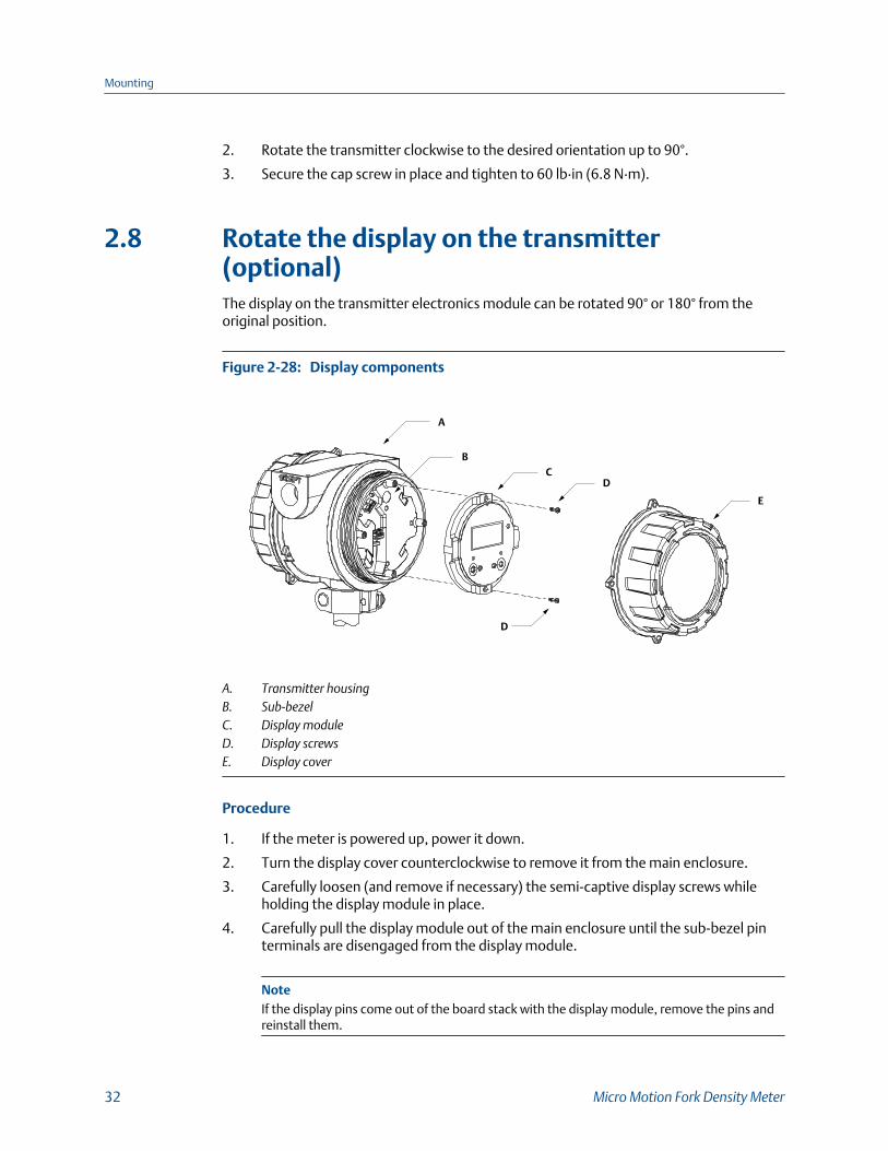
2.7 Rotate the electronics on the meter (optional)You can rotate the transmitter on the meter up to 90°.
1. Using a 4 mm hex key, loosen the cap screw that holds the transmitter in place.
Component to secure transmitter in placeFigure 2-27:
A
A. M5 socket-head cap screw
Mounting
Installation Manual 31
2. Rotate the transmitter clockwise to the desired orientation up to 90°.
3. Secure the cap screw in place and tighten to 60 lb·in (6.8 N·m).
2.8 Rotate the display on the transmitter(optional)The display on the transmitter electronics module can be rotated 90° or 180° from theoriginal position.
Display componentsFigure 2-28:
BC
D
A
D
E
A. Transmitter housingB. Sub-bezelC. Display moduleD. Display screwsE. Display cover
Procedure
1. If the meter is powered up, power it down.
2. Turn the display cover counterclockwise to remove it from the main enclosure.
3. Carefully loosen (and remove if necessary) the semi-captive display screws whileholding the display module in place.
4. Carefully pull the display module out of the main enclosure until the sub-bezel pinterminals are disengaged from the display module.
NoteIf the display pins come out of the board stack with the display module, remove the pins andreinstall them.
Mounting
32 Micro Motion Fork Density Meter

5. Rotate the display module to the desired position.
6. Insert the sub-bezel pin terminals into the display module pin holes to secure thedisplay in its new position.
7. If you have removed the display screws, line them up with the matching holes on thesub-bezel, then reinsert and tighten them.
8. Place the display cover onto the main enclosure.
9. Turn the display cover clockwise until it is snug.
10. If appropriate, power up the meter.
Mounting
Installation Manual 33

3 WiringTopics covered in this chapter:
• Terminals and wiring requirements
• Explosion-proof/flameproof or non-hazardous output wiring
• Processor wiring for remote-mount 2700 FOUNDATION™ fieldbus option
• Wiring to external devices (HART multidrop)
• Wiring to signal converters and/or flow computers
3.1 Terminals and wiring requirementsThree pairs of wiring terminals are available for transmitter outputs. These outputs varydepending on your transmitter output option ordered. The Analog (mA), Time PeriodSignal (TPS), and Discrete (DO) outputs require external power, and must be connected toan independent 24 VDC power supply.
The screw connectors for each output terminal accept a maximum wire size of 14 AWG(2.5 mm2).
Important
• Output wiring requirements depend on whether the meter will be installed in a safe area or ahazardous area. It is your responsibility to verify that this installation meets all corporate,local, and national safety requirements and electrical codes.
• If you will configure the meter to poll an external temperature or pressure device, you mustwire the mA output to support HART communications. You may use either HART/mA single-loop wiring or HART multi-drop wiring.
Transmitter outputsTable 3-1:
Transmitter version
Output channels
A B C
Analog 4–20 mA + HART 4–20 mA Modbus/RS-485
Processor for remote-mount 2700FOUNDATION™ fieldbus transmitter
Disabled Disabled Modbus/RS-485
Time period signal (TPS) 4–20 mA + HART(passive)
Time Period Sig-nal (TPS)
Modbus/RS-485
Discrete 4–20 mA + HART(passive)
Discrete output Modbus/RS-485
Wiring
34 Micro Motion Fork Density Meter

3.2 Explosion-proof/flameproof or non-hazardousoutput wiring
3.2.1 Wire the Analog outputs version in an explosion-proof/flameproof or non-hazardous area
CAUTION!
Meter installation and wiring should be performed by suitably trained personnel only inaccordance with the applicable code of practice.
Procedure
Wire to the appropriate output terminal and pins (see Figure 3-1).
Wiring
Installation Manual 35

Wiring the Analog outputsFigure 3-1:
mA1+HART
RS-485
PWR
mA2
AAB
RS-485 A
RS-485 B
C
DB
B
A
A
A
A. 24 VDCB. Rload (250 Ω resistance)C. HART-compatible host or controller; and/or signal deviceD. Signal device
NoteFor operating the milliamp outputs with a 24V supply, a maximum total loop resistance of 657 Ω isallowed.
CAUTION!
• To meet the EC Directive for Electromagnetic Compatibility (EMC), use a suitableinstrumentation cable to connect the meter. The instrumentation cable should have individualscreens, foil or braid over each twisted pair, and an overall screen to cover all cores. Wherepermissible, connect the overall screen to earth at both ends (360° bonded at both ends).Connect the inner individual screens at only the controller end.
• Use metal cable glands where the cables enter the meter amplifier box. Fit unused cable portswith metal blanking plugs.
Wiring
36 Micro Motion Fork Density Meter

3.2.2 Wire the Time Period Signal (TPS) or Discrete outputversion in an explosion-proof/flameproof or non-hazardous area
CAUTION!
Meter installation and wiring should be performed by suitably trained personnel only inaccordance with the applicable code of practice.
Procedure
Wire to the appropriate output terminal and pins (see Figure 3-2).
Wiring
Installation Manual 37
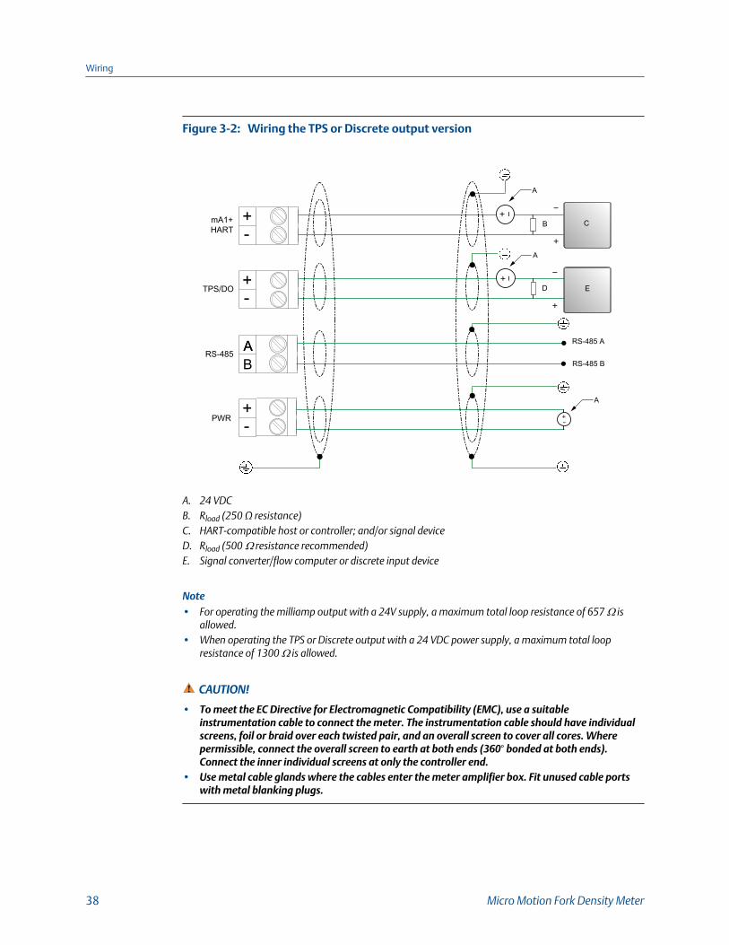
Wiring the TPS or Discrete output versionFigure 3-2:
mA1+HART
RS-485
PWR
TPS/DO
AAB
RS-485 A
RS-485 B
C
ED
B
A
A
A
A. 24 VDCB. Rload (250 Ω resistance)C. HART-compatible host or controller; and/or signal deviceD. Rload (500 Ω resistance recommended)E. Signal converter/flow computer or discrete input device
Note• For operating the milliamp output with a 24V supply, a maximum total loop resistance of 657 Ω is
allowed.• When operating the TPS or Discrete output with a 24 VDC power supply, a maximum total loop
resistance of 1300 Ω is allowed.
CAUTION!
• To meet the EC Directive for Electromagnetic Compatibility (EMC), use a suitableinstrumentation cable to connect the meter. The instrumentation cable should have individualscreens, foil or braid over each twisted pair, and an overall screen to cover all cores. Wherepermissible, connect the overall screen to earth at both ends (360° bonded at both ends).Connect the inner individual screens at only the controller end.
• Use metal cable glands where the cables enter the meter amplifier box. Fit unused cable portswith metal blanking plugs.
Wiring
38 Micro Motion Fork Density Meter
3.3 Processor wiring for remote-mount 2700FOUNDATION™ fieldbus option
3.3.1 RS-485 entity parameters for the remote-mount 2700FOUNDATION™ fieldbus option
DANGER!
Hazardous voltage can cause severe injury or death. To reduce the risk of hazardous voltage,shut off power before wiring the meter.
DANGER!
Improper wiring in a hazardous environment can cause an explosion. Install the meter only inan area that complies with the hazardous classification tag on the meter.
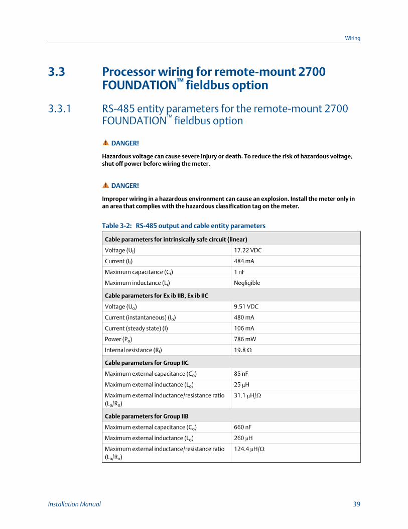
RS-485 output and cable entity parametersTable 3-2:
Cable parameters for intrinsically safe circuit (linear)
Voltage (Ui) 17.22 VDC
Current (Ii) 484 mA
Maximum capacitance (Ci) 1 nF
Maximum inductance (Li) Negligible
Cable parameters for Ex ib IIB, Ex ib IIC
Voltage (Uo) 9.51 VDC
Current (instantaneous) (Io) 480 mA
Current (steady state) (I) 106 mA
Power (Po) 786 mW
Internal resistance (Ri) 19.8 Ω
Cable parameters for Group IIC
Maximum external capacitance (Co) 85 nF
Maximum external inductance (Lo) 25 µH
Maximum external inductance/resistance ratio(Lo/Ro)
31.1 µH/Ω
Cable parameters for Group IIB
Maximum external capacitance (Co) 660 nF
Maximum external inductance (Lo) 260 µH
Maximum external inductance/resistance ratio(Lo/Ro)
124.4 µH/Ω
Wiring
Installation Manual 39

3.3.2 Connect 4-wire cable
4-wire cable types and usageMicro Motion offers two types of 4-wire cable: shielded and armored. Both types containshield drain wires.
The cable supplied by Micro Motion consists of one pair of red and black 18 AWG(0.75 mm2 wires for the VDC connection, and one pair of white and green 22 AWG(0.35 mm2 wires for the RS-485 connection.
User-supplied cable must meet the following requirements:
• Twisted pair construction.
• Applicable hazardous area requirements, if the core processor is installed in ahazardous area.
• Wire gauge appropriate for the cable length between the core processor and thetransmitter.
• Wire gauge of 22 AWG or larger, with a maximum cable length of 1000 feet.
Prepare a cable with a metal conduit
Prerequisites
NoteIf you are installing unshielded cable in continuous metallic conduit with 360º termination shielding,you only need to prepare the cable – you do not need to perform the shielding procedure.
Procedure
1. Remove the integral processor cover using a flat-blade screw driver.
2. Run the conduit to the sensor.
3. Pull the cable through the conduit.
4. Cut the drain wires and let them float at both ends of the conduit.
Prepare a cable with user-supplied cable glands
Prerequisites
ImportantFor user-supplied cable glands, the gland must be capable of terminating the drain wires.
Procedure
1. Remove the core processor cover using a flat-blade screw driver.
2. Pass the wires through the gland.
3. Terminate the shield and drain wires inside the gland.
Wiring
40 Micro Motion Fork Density Meter
4. Assemble the gland according to vendor instructions.
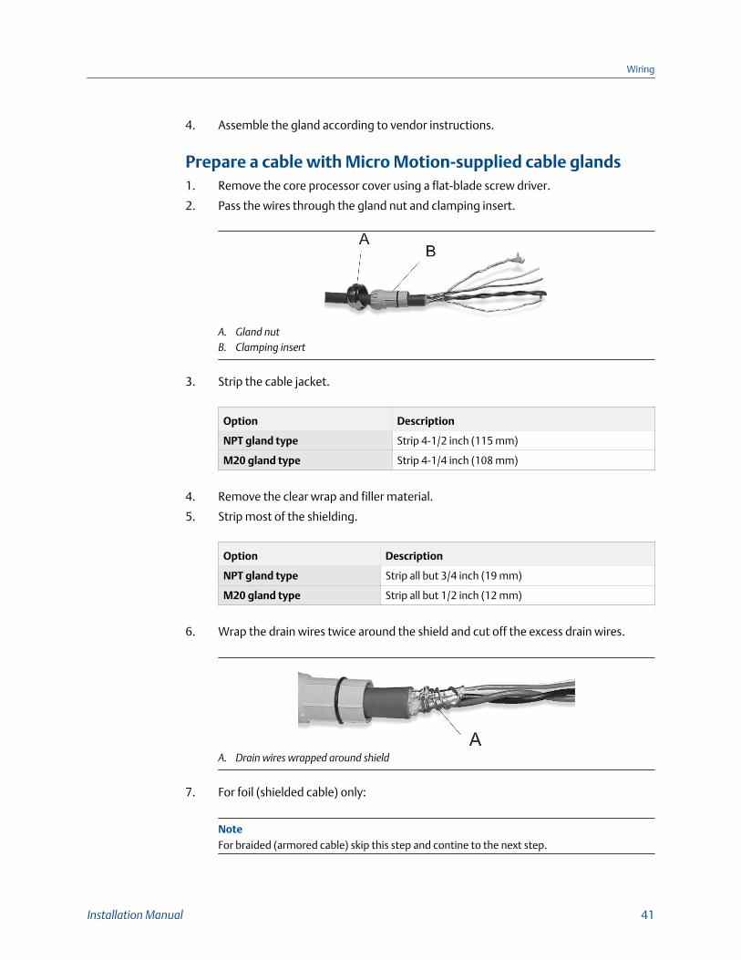
Prepare a cable with Micro Motion-supplied cable glands1. Remove the core processor cover using a flat-blade screw driver.
2. Pass the wires through the gland nut and clamping insert.
A. Gland nutB. Clamping insert
3. Strip the cable jacket.
Option Description
NPT gland type Strip 4-1/2 inch (115 mm)
M20 gland type Strip 4-1/4 inch (108 mm)
4. Remove the clear wrap and filler material.
5. Strip most of the shielding.
Option Description
NPT gland type Strip all but 3/4 inch (19 mm)
M20 gland type Strip all but 1/2 inch (12 mm)
6. Wrap the drain wires twice around the shield and cut off the excess drain wires.
A. Drain wires wrapped around shield
7. For foil (shielded cable) only:
NoteFor braided (armored cable) skip this step and contine to the next step.
Wiring
Installation Manual 41
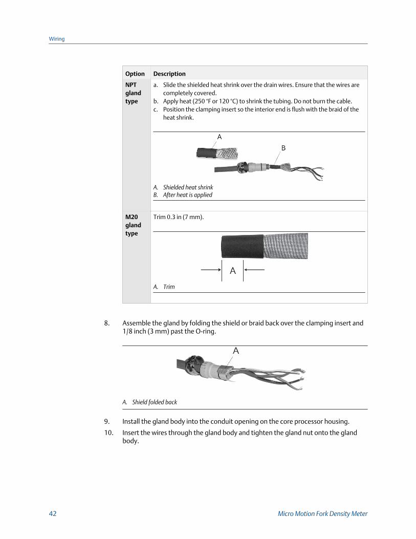
Option Description
NPTglandtype
a. Slide the shielded heat shrink over the drain wires. Ensure that the wires arecompletely covered.
b. Apply heat (250 °F or 120 °C) to shrink the tubing. Do not burn the cable.c. Position the clamping insert so the interior end is flush with the braid of the
heat shrink.
A. Shielded heat shrinkB. After heat is applied
M20glandtype
Trim 0.3 in (7 mm).
A. Trim
8. Assemble the gland by folding the shield or braid back over the clamping insert and1/8 inch (3 mm) past the O-ring.
A. Shield folded back
9. Install the gland body into the conduit opening on the core processor housing.
10. Insert the wires through the gland body and tighten the gland nut onto the glandbody.
Wiring
42 Micro Motion Fork Density Meter

A. Shield folded backB. Gland body
3.3.3 Processor wiring for the remote-mount 2700FOUNDATION fieldbus™ optionThe following figure illustrates how to connect the individual wires of a 4-wire cable to theprocessor terminals. For detailed information on mounting and wiring to the remote-mount 2700 FOUNDATION fieldbus transmitter, see the transmitter installation manual.
Processor (Modbus/RS-485) connections to the remote-mount 2700 FFtransmitter
Figure 3-3:
ABCD
A. White wire to RS-485/A terminalB. Green wire to RS-485/B terminalC. Red wire to Power supply (+) terminalD. Black wire to Power supply (–) terminal
Important• To meet the EC Directive for EMC (Electromagnetic Compatibility), it is recommended that the
meter be connected using a suitable instrumentation cable. The instrumentation cable should haveindividual screen(s), foil or braid over each twisted pair and an overall screen to cover all cores.Where permissible, the overall screen should be connected to earth at both ends (360° bonded atboth ends). The inner individual screen(s) should be connected at only one end, the controller end.
• Metal cable glands should be used where the cables enter the meter amplifier box. Unused cableports should be fitted with metal blanking plugs.
Wiring
Installation Manual 43

3.4 Wiring to external devices (HART multidrop)You can wire up to three external HART devices with the meter. The following informationprovides wiring diagrams for making those connections in safe and hazardousenvironments.
3.4.1 Wire mA1 in a HART multi-drop environment
ImportantTo wire power and outputs, see Wire power and outputs in a HART single-loop environment.
Wiring
44 Micro Motion Fork Density Meter

Wire mA1 in a HART multi-drop environmentFigure 3-4:
250 Ω
24 VDC
mA1
+H
ART
A
B
C
E
D
A. HART Device 1B. HART Device 2C. HART Device 3D. Meter (mA+/HART output)E. HART/Field Communicator
CAUTION!
• To meet the EC Directive for Electromagnetic Compatibility (EMC), use a suitable instrumentation cable to connectthe meter. The instrumentation cable should have individual screens, foil or braid over each twisted pair, and anoverall screen to cover all cores. Where permissible, connect the overall screen to earth at both ends (360° bondedat both ends). Connect the inner individual screens at only the controller end.
• Use metal cable glands where the cables enter the meter amplifier box. Fit unused cable ports with metalblanking plugs.
Wiring
Installation Manual 45
3.5 Wiring to signal converters and/or flowcomputersFor meters with a Time Period Signal (TPS) output, you can wire the meter to an signalconverter or flow computer directly. The following information provides wiring diagramsfor making those connections in safe and hazardous environments.
When wiring the meter to an active HART host or signal converter/flow computer, you arenot required to provide external power to the output connections. These active devicesprovide the 24 VDC necessary for these connections.
Wiring
46 Micro Motion Fork Density Meter
3.5.1 Wire to a signal converter/flow computer in anexplosion-proof/flameproof or non-hazardous area
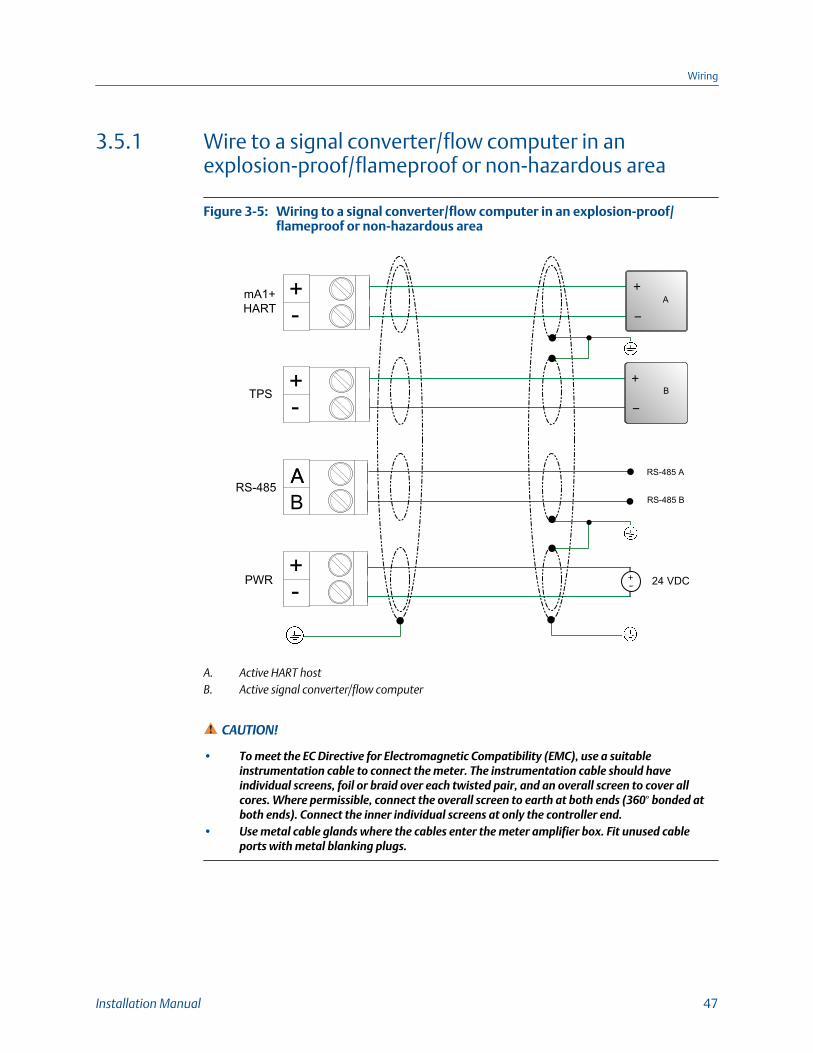
Wiring to a signal converter/flow computer in an explosion-proof/flameproof or non-hazardous area
Figure 3-5:
mA1+HART
RS-485
PWR
TPS
AAB
24 VDC
RS-485 A
RS-485 B
A
B
A. Active HART hostB. Active signal converter/flow computer
CAUTION!
• To meet the EC Directive for Electromagnetic Compatibility (EMC), use a suitableinstrumentation cable to connect the meter. The instrumentation cable should haveindividual screens, foil or braid over each twisted pair, and an overall screen to cover allcores. Where permissible, connect the overall screen to earth at both ends (360° bonded atboth ends). Connect the inner individual screens at only the controller end.
• Use metal cable glands where the cables enter the meter amplifier box. Fit unused cableports with metal blanking plugs.
Wiring
Installation Manual 47
4 Grounding
The meter must be grounded according to the standards that are applicable at the site.The customer is responsible for knowing and complying with all applicable standards.
Prerequisites
Micro Motion suggests the following guides for grounding practices:
• In Europe, EN 60079-14 is applicable to most installations, in particular Sections12.2.2.3 and 12.2.2.4.
• In the U.S.A. and Canada, ISA 12.06.01 Part 1 provides examples with associatedapplications and requirements.
• For IECEx installations, IEC 60079-14 is applicable.
If no external standards are applicable, follow these guidelines to ground the meter:
• Use copper wire, 18 AWG (0.75 mm2) or larger wire size.
• Keep all ground leads as short as possible, less than 1 Ω impedance.
• Connect ground leads directly to earth, or follow plant standards.
CAUTION!
Ground the meter to earth, or follow ground network requirements for the facility. Impropergrounding can cause measurement error.
Procedure
Check the joints in the pipeline or tank installation.
- If the joints in the pipeline or tank are ground-bonded, the meter is automaticallygrounded and no further action is necessary (unless required by local code).
- If the joints in the pipeline or tank are not grounded, connect a ground wire to thegrounding screw located on the meter electronics.
Grounding
48 Micro Motion Fork Density Meter

Grounding
Installation Manual 49

*MMI-20020989*MMI-20020989
Rev AD
2017
Micro Motion Inc. USAWorldwide Headquarters7070 Winchester CircleBoulder, Colorado 80301T +1 303-527-5200T +1 800-522-6277F +1 303-530-8459www.emerson.com
Micro Motion EuropeEmerson Automation SolutionsNeonstraat 16718 WX EdeThe NetherlandsT +31 (0) 70 413 6666F +31 (0) 318 495 556www.micromotion.nl
Micro Motion AsiaEmerson Automation Solutions1 Pandan CrescentSingapore 128461Republic of SingaporeT +65 6777-8211F +65 6770-8003
Micro Motion United KingdomEmerson Automation SolutionsEmerson Process Management LimitedHorsfield WayBredbury Industrial EstateStockport SK6 2SU U.K.T +44 0870 240 1978F +44 0800 966 181
Micro Motion JapanEmerson Automation Solutions1-2-5, Higashi ShinagawaShinagawa-kuTokyo 140-0002 JapanT +81 3 5769-6803F +81 3 5769-6844
©2017 Micro Motion, Inc. All rights reserved.
The Emerson logo is a trademark and service mark of EmersonElectric Co. Micro Motion, ELITE, ProLink, MVD and MVD DirectConnect marks are marks of one of the Emerson AutomationSolutions family of companies. All other marks are property of theirrespective owners.