Embed Size (px)
Citation preview
THE AMERICAN SOCIETY OF MECHANICAL ENGINEERS345 E. 47 St., New York, N.Y. 10017
The Society shall not be responsible for statements or opinions advanced in papers or in dis-cussion at meetings of the Society or of its Divisions or Sections, or printed in its publications.Discussion Is printed only if the paper is published In an ASME Journal. Papers are availablefrom ASME for fifteen months after the meeting.Printed in USA.
86-GT-209
Mechanical Reliability Operational Experience in theModern High Temperature Industrial Gas Turbine
J. KORTAGas Turbine Engineering
Turbine & Generator DivisionWestinghouse Canada Inc.Hamilton, Ontario, Canada
ABSTRACT
The CW352 two shaft industrial type gas turbinewas first put in commercial service in 1979. By mid1985 units in simple cycle and regenerative modeshave accumulated in excess of 200,000 hrs. ofoperation, with lead units in excess of 50,000 hrs.simple cycle mode and 35,000 hrs. in regenerativecycle mode. The paper discusses the operationalexperience with emphasis on early field problems andtheir solutions.
INTRODUCTION
The gas turbine, which is the subject of thispaper, is the Canadian Westinghouse model CW352which entered commercial service in September of1979. This machine was designed for applications inboth the petrochemical process and natural gastransmission markets.
THE GAS TURBINE ENGINE
To explain our experiences with the engine itis necessary to briefly describe it. The design ofthe CW352 engine drew heavily on our experience withthe earlier Westinghouse family of two shaft gasturbines, combined with a somewhat modifiedaxial-compressor design from the W191 model and hightemperature turbine technology derived from theWestinghouse Electric model W251. The major featureof new design was the power turbine which featuresvariable area stator vanes and high aspect ratio tipshrouded rotating blades. The close coupling of thegas generator and power turbine stages usingoverhung bearings was also a departure from ourprevious two shaft designs.
The major design objectives for the enginewere, very much in this order, reliability, minimalmaintenance and high thermal efficiency. Thislatter objective is realized by the use of theregenerator and the alliance with waste heatrecovery in the simple cycle mode. Both cyclesdictate relatively low pressure ratios for highoverall efficiencies.
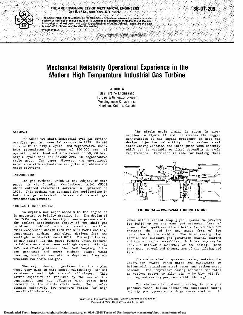
The simple cycle engine is shown in crosssection in Figure lA and illustrates the ruggedconstruction of the engine necessary to meet thedesign objective reliability. The carbon steelinlet casing contains the inlet guide vane assemblywhich can be variable or fixed depending on cyclerequirements. Provision is made for heating these
FIGURE 1A — CW-352MA TURBINE ENGINE
vanes with a closed loop glycol system to preventice build up on the vane and attendant loss ofpower. Our experience in northern climates does notindicate the need for any other form of iceprotection in the machine. The inlet casing alsocarries the outboard gas generator journal bearingand thrust bearing assemblies. Both bearings may beserviced without disassembly of the casing. Bothbearings, journal and thrust, are of the tilting padtype.
The carbon steel compressor casing contains thecompressor stator vanes which are fabricated inhalves with stainless steel vanes and carbon steelshrouds. The compressor casing contains manifoldsat various stages to allow air to be bled off forcooling and sealing purposes within the engine.
The chrome-moly combustor casing is purely apressure vessel bolted between the compressor casingand the gas generator turbine outer casings. It
Presented at the International Gas Turbine Conference and ExhibitDusseldorf, West Germany—June 8-12, 1986
Copyright © 1986 by ASME
Downloaded From: https://asmedigitalcollection.asme.org/ on 06/04/2018 Terms of Use: http://www.asme.org/about-asme/terms-of-use

carries the eight combustor baskets, canted foraccessibility, and the fuel nozzles. The basketsare interconnected by cross flame tubes and twobaskets feature igniters of the high energy surfacedischarge type.
The six strut spider casing bolted andspigotted between the compressor and gas generatorcasings is the rear structural member of the gasgenerator section and supports the inboard gasgenerator journal bearing and its sealing system.This bearing is also of the pivoted shoe type. Acoaxial pipe system supplies cooling air to thisbearing and vents the system through the top half ofthe combustor shell. Similar pipes in the lowerhalf supply and drain the oil to and from thebearing.
The gas generator turbine casing consists oftwo concentric parts. The outer casing is thestructural member and carries the inner casingconcentrically on radial pins. The inner casingcarries the stationary nozzle vanes for the gasgenerator turbine. The vanes are individually castalloy segments with internal air cooling. The powerturbine casing carries the variable power turbinevanes, each of which consists of two cast alloysegments, a fixed leading edge and a movabletrailing edge. The trailing edge is hinged to theleading edge and is moveable through approximatelysixteen degrees. The moveable trailing edges arepositioned by an externally mounted unison ringoperated by an electrohydraulic actuator controlled
by the turbine governor. The casing also carriesthe external cooling air manifold which suppliesintermediate-stage compressor air to cool the sealareas of the power turbine assembly.
The exhaust diffuser is bolted to the rear ofthe power turbine cylinder and supports thetangential struts which supports the power turbinebearing system, consisting of two overhung tiltingpad journal bearings and a tilting pad thrustbearing.
All casings throughout the turbines arehorizontally split for ease of maintenance.
The gas generator rotor consists of amulti-stage axial compressor, featuring forged alloydiscs shrunk on a forged alloy shaft. The stainlesssteel compressor blades have dovetail roots fittingin slots in the disc, each blade being locked inplace by a spring loaded pin. Individual blades maybe removed without disturbing adjacent blades, rows,or removing the rotor. This shaft is bolted andspigotted to the turbine rotor consisting of aspindle to which the turbine disc is bolted andkeyed. The turbine rotor is cantilevered rearwardfrom the inboard bearing.
The cast nickel alloy turbine blades haveextended "fir tree" roots fitting into side entryslots in the disc. The blades are cooled bycompressor exit air entering the base of the bladeand exiting through the top. A lock plate systemretains the blades in the disc and controls the coolair passages. Between the two turbines a seal wallseparates cooling air paths between the two discs.
The power turbine rotor is a single alloy steelforging, the blades being retained in the disc in asimilar fashion to the gas generator turbine.
The power turbine blades are forged and featureinterlocking tip shrouds to improve tip sealing andto damp blade vibration.
The regenerative engine, Figure 1B, isessentially similar to the simple cycle, but adividing wall is placed in the combustor cylinderand take off and return ports provided for the airto and from the regenerator.
FIGURE 1B — CW-352MA TURBINE ENGINE
In the interests of flexibility the engine isdesigned so that it may be built with a 15, 16 stageor 17 stage axial compressor depending on thecustomer's performance and cycle requirements.
COMBUSTOR BASKET
Each of the eight CW352 combustor assembliesconsists of three major parts, the primary basket,the secondary basket and the transition section.Sealing between the cylindrical sliding surfaces atthe primary basket to the secondary basket and thesecondary basket to transition section interfaces isaccomplished by means of two layers of radiallyflexible fingers, or spring clips. The layers areattached to each other by spotwelds (Figure 2).
INTER CLIPSPOT WELDS
KEYHOLE
TYPICAL CRACKPROPAGATION
FIGURE 2 — CW352 SPRINGCLIP FAILURE
In the regenerative machine a third set ofspring clips attached to the secondary basket sealagainst the cylinder in the dividing wall, betweenthe hot and cold sections of the combustor cylinder,Figure 1B.
Cracking and breakage of spring-clips in bothprimary and secondary baskets has been a significantproblem in the simple cycle engine. Figure 2 showsa typical spring-clip cracking found in earlycombustor inspections which has been identified asfatigue distress.
2
Downloaded From: https://asmedigitalcollection.asme.org/ on 06/04/2018 Terms of Use: http://www.asme.org/about-asme/terms-of-use

OUTER CLIPS DEBRIS RING
INNERCLIPS INNER CLIP
BUTTERFLYOUTERCLIPS
TRANSITION
EARS
LOWERFLANGE
RADIAL COLLPASE
SUPPORTBRACKET
UPPERFLANGE
SEAL LANDSEAL LAND MOUNTINGBOLT HERE
GALLING
Modifications introduced during this time havebeen aimed at reducing the probability of vibrationin the spring-clips by increasing cold pre-load andholding together the inner and outer row of clipswith the so-called "butterflies" (Figure 3). Thesemodifications have effected some improvement buthave not solved the problem.
FIGURE 3 — CW352 BASKET SPRING CLIPS
The breakage of spring-clips can result infractured pieces entering the hot gas path anddamaging both compressor turbine and power turbineblading. To date this impact damage has been minorbut to prevent this, debris rings were welded to thebaskets as shown in Figure 3 to trap metalfragments. These have proved partially successfulin that they effectively prevented the largerfragments from entering the gas path.
In all cases, cracking has been determined toemanate from the heat affected zone of the interclipspotwelds. Here, where the largest stressconcentration exists, fatigue cracks begin.Vibratory loads cause the cracks to propagate untilthe clip separates. It is believed that the problemwas aggravated by the sensitization of the Hastelloymaterial when exposed for prolonged periods totemperatures of 425 °C to 870 °C. This conditionresults in an increased crack propagation rate and adecreased allowable fatigue stress. However, itshould be noted that many components do successfullyoperate under these conditions.
Regenerative cycle engines did not commencecommercial service until the end of 1980. It isnoteworthy that the subsequent experience has beenvery different from the simple cycle engine. Nobroken spring-clips have been found even with timesbetween inspections of 14,000 hrs. Minor to severegalling on spring-clip surfaces has however been aproblem and baskets have been changed out for thisreason. There have also been some instances of lossof spring-clip pre-load.
In order to understand the cause of spring-clipfatigue vibration testing of combustor assemblieswas conducted. The test showed that no predominantspring-clip resonances exist and that regenerativebaskets have far superior damping. In view of thesefacts it was concluded that the driving force behind
the fatigue damage is vibration of the combustorbasket/transition-duct assembly, possibly as aresult of aerodynamic excitation. This wouldexplain why the regenerative baskets have superiorspring-clip life as a result of less secondarybasket motion, since the secondary baskets have anadditional support at the dividing wall.
The elimination of spring-clip failures can beapproached from two directions. The first is toincorporate structural improvement to withstand theimposed vibration. The second is to reduce thevibration itself. It is believed that the newspring-clip design does both.
The improved spring-clip design is based onexperimental testing with various configurations.This design incorporates spring-clips which are0.078 inch thick instead of 0.050 inch andeliminates the interclip spotwelds. Thiscombination reduces bending stresses and removes themajor stress concentration. Hence, a largervibration amplitude can be tolerated before fatiguecracks develop. In addition, the preload force willbe substantially increased, reducing vibration thrugreater basket support stiffness and improvedfrictional damping. The spring-clip material willbe changed from Hastelloy X to Inconel X-750 whichpossesses far superior high temperature properties.This will reduce preload relaxation which has beenexperienced in varying degrees. Furthermore, thefatigue strength of this material is superior andprovides an additional margin of safety.
This new spring-clip design retains both thebutterfly clips and debris ring. A space betweenleaves will now be provided at the keyhole (Figure3) to insure that each leaf can operateindependently. Finally, the spring-clips and matingcomponents will be hardfaced with Triballoy T400 toreduce fretting damage.
In conclusion, it is believed that thespring-clip's vibration tolerance will be greatlyimproved and that reliability will be greatlyincreased.
TRANSITION-DUCT FLANGES
The eight transition ducts from a completeannulus at their interface with the compressorturbine nozzle diaphragms. Exit from each ductbecomes a segment of this annulus (Figure 4). In
FIGURE 4
3
Downloaded From: https://asmedigitalcollection.asme.org/ on 06/04/2018 Terms of Use: http://www.asme.org/about-asme/terms-of-use

'ex's
IF 11.FULL LENGTHDOUBLE RAILWITH REDUCEDCLEARANCE
TRANSITION(LOOKING AGAINST) -
THE FLOW
DUAL STRUTS
SEAL LAND
SUPPORT TAB
ADDITIONALSTIFFENINGFLANGE
SEAL
SEAL ASS'YCROSS SECTION
DUAL SEAL LAND BOLTS
NEW DESIGN
REDUCEDCONTACT AREA
SEAL ASS'YCROSS SECTION
OLD DESIGN
TRANSITION
order to retain this shape flanges are provided onupper and lower accurate surfaces, as shown. Thetransition-duct/nozzle-diaphragm interface is sealedon the inner flowpath by eight seal lands, eachretained on a lower flange by a single bolt. Severewear and cracking has been experienced in the lowerflange around the bolt hole. In one case thiscracking propogated into the transition body andcaused a major shut down due to the separation of apiece of transition section.
Other problems in the transition section havebeen galling of the upstream mouth due tospring-clip fretting, and the radial collapse of thedownstream mouth. These have been minor.
However, the estimated stress levels in thefailure zone, coupled with the fact that thisproblem has not been more pronounced, suggests thatdamage to the seal flange is a necessity for fatiguecracks to initiate. Most scenarios to explain thisdamage involve the loss of contact force between thetransition seal land and its static seal. Thisassembly is depicted in Figure 5. The lightercontact between these components would allowexcessive seal land vibratory motion. As a result,the transition seal flange which contains thepivoting bolt would experience excessive wear andinitiate fatigue cracks.
would result in a pull out force on the flange whichwould directly fracture the flange.
Regenerative cycle engine experience has beendifferent from the simple cycle engine. This hasalso been complicated by partial use of a differentmaterial, Nimonic C.263 instead of Hastelloy X.However, cracking around the land seal bolt hole hasnot been a problem. Minor cracking around themounting support bracket and seal ears, see Figure4, has developed and these weld cracks coupled withthe difficulty of repairing this material are thereasons for its use being discontinued.
Although the actual cause of failure is notknown, we believe that all possibilities have beenaddressed through attention to the followingspecific deficiencies:
1. transition-duct natural frequency2. transition-duct mouth warpage3. transition I.D. seal flange fatigue
strength4. seal preload5. seal land wear problems
Other reliability and performance deficienciesaddressed are:
6. seal land/static seal air leakage
FIGURE 5 — TRANSITION/SEAL LAND DETAILS
The loss in contact force can be explained by anumber of occurrences:
1. Transition-duct installed radially out ofposition.
2. Seal held down by adjacent seals thru theinter-locking joint plates.
3. Seal land tab breakage resulting frompressure forces on an assembly with aloose pivot bolt.
4. Radially outward warpage of thetransition-duct mouth at the pivot bolthole.
Damage to the transition-duct seal flange as aresult warpage could also occur due to seal landbinding. This would occur when warpage is soextreme that the seal land ends contact thetransition. Once this happened all further warpage
Our modifications to overcome these problemsare as follows:
The transition-duct mouth will now employ anadditional flange adjacent to the seal land flange,as depicted in Figure 5. This modification isintended to re-tune the bending mode vibration ofthe mouth and thus reduce the driving force behindthe fatigue cracking. The effectiveness of thischange has been shown in rig tests. This extraflange also significantly lowers the maximum stresslevel in the vicinity of the cracking and shouldalso reduce the warpage.
The seal land now consists of dual continuousrails which employ a tight axial clearance and isattached to the flange by a bolt at each end insteadof one at the center. In addition a knife edge hasbeen added on the static seal interface. The newand old designs are compared in Figure 5. Theintent of these changes is as follows. The dualrails will reduce compressor discharge air leakageand at the same time prevent the seal land fromtipping. The problem of breakage of the support tabwill be eliminated. The new dual-retaining boltsystem will prevent large vibratory motion which waspossible with the old pivoting bolt design when sealpreload was low. This change also allows thecurrent type of transition-duct warpage to occurwithout affecting seal land position or imposingextra loads. The knife edge has been added toimprove sealing between the seal and seal land bychanging a surface contact to a line contact. It isalso intended to wear in and thus accommodatemisalignment which previously resulted in a gap.
In order to accommodate radial misalignmentbetween the seal land and its seal the interferencehas been increased from .065" to .190". Thecircumferential interlocking joint plates betweenseals have been changed to single plates. Thisallows the seals to seat themselves individually onthe seal lands for optimum sealing and preload.
4
Downloaded From: https://asmedigitalcollection.asme.org/ on 06/04/2018 Terms of Use: http://www.asme.org/about-asme/terms-of-use
CYLINDER BOLTING
All problems connected with cylinder bolting onCW352 machines have been related to thread seizureon dis-assembly. Many instances of complete seizurehave been encountered, resulting in considerabletime spent in cutting bolts and re-drilling andtapping holes. In extreme cases, threads have beendamaged to the extent that the insertion ofHeli-Coils was required.
An unfortunate choice of anti-seize compoundswas possibly a contributing factor in the early boltseizure problems. The compound originally specifiedwas a standard product, that has been used for manyyears at Westinghouse.
After this experience a laboratory test wasconducted at Westinghouse to evaluate severalcompounds. Using Military Specification MIL-A-907Das a guide, a test procedure was developed for 422stainless steel bolts threaded into Chrome-Molyblocks to simulate actual cylinder boltingconditions. Normal tightening torques were appliedand several anti-seize compounds were tested.
A wide variation in the performance of theseanti-seize compounds was found. Fel-Pro C-100 wasthe best in several respects. It gave the lowesttorque for both assembly and disassembly, and theleast scatter in disassembly torques.
It was also found that bolts that were testeddry seized on disassembly, but none of the boltstreated with anti-seize compounds seized or galledon disassembly.
Following these tests Fel-Pro C-100 wasspecified on all cylinder joint bolts.
The original designs of the bolted joints onthis machine were based on the usual Westinghousepractice of stressing carbon steel bolts to 30,000p.s.i. and alloy steel bolts to 45,000 p.s.i. onassembly. To increase the ease of dis-assembly ofalloy bolts on the hot end of -the unit, it wassuggested that a reduced tightening torque might beeffective. The design of all joints was reviewed,and in many cases it was found that a reduction inbolt tightening stress to 30,000 p.s.i. wasfeasible. Specified tightening torques were thenreduced in line with these new stress values.
To reduce the possibility of seizing caused bypoor threadfinish, an assembly method for boltedjoints was developed. The purpose of this procedurewas to detect any tapped holes or bolt threads thatwere defective, and to improve the surface finish ofthe threads by bedding them in on original assembly.
The bolting procedure consists of threading thebolt into the tapped hole with a maximum torque of 5ft. lbs., until it has seated firmly against theflange surface. If this is not possible the threadsare inspected and any defects rectified. The boltis then tightened to the specified torque. Finallythe bolt is loosened completely and re-tightened tothe specified torque.
Many of the cylinder bolts used in the CW352turbine have been produced with a thread surfacefinish that was quite rough. This resulted from theuse of single point tooling to machine the threads,
instead of grinding or rolling. When this possiblecause of seizure was recognized, drawings for allcritical bolts were changed to call for a 32 microinch finish on threads, and bolts were purchasedfrom suppliers that provided rolled threads whereverpossible.
COMPRESSOR TURBINE CYLINDER DISTORTION
The CW352 gas turbine casings are split at thehorizontal centerline to facilitate disassembly andmaintenance. This type of cylinder will be subjectto some degree of distortion if, during operation, asignificant thermal gradient exists radially acrossthe cylinder. The degree of distortion will dependon individual cylinder design. The most usualthermal gradient in the gas turbine casing is fromhigh to low temperature radially outwards across thecasing. The hotter inside surface yields and whenthe engine is not operating the joint opens at theinside and the casing grows in at the joint, and outat the vertical diameter. The casing tends toreturn towards the round condition when returned tooperating temperature. This change in curvature isprogressive occurring over a number of cycles.
Compressor turbine inner cylinder casingdistortion has been quite severe on the regenerativemachines but has not been a problem on the simpleengines. This is accounted for by the lower thermalgradient across the cylinder in the latter enginesdue to the difference in gas path radial temperatureprofile.
The distortion of the compressor turbine casingis significant because this casing carries thecompressor turbine tip seal segments for thecompressor turbine rotor blades.
The distortion radially inwards leads to lossof tip clearance and blade rubs and seal damage,distortion radially outwards leads to increased tipclearance and loss of performance.
This problem in compounded in this cylinder bydistortion of the compressor turbine tip sealsthemselves. These seals have bowed radially inwardswith prolonged running, see Figure 6. Thisdistortion occurs as a result of material creepunder conditions of operational stress andtemperature.
The inner cylinder has been completely revisedto reduce the temperature gradient across its radialthickness during operation, and thus minimizeovality (see Figure 6). Modifications have beenmade to isolate various sources of heat, and thusreduce heat transfer to the inner surface of thecylinder. By insulating the downstream verticalwall of the cylinder using high temperature insula-tion with a reflective cover, thermal radiation fromthe power turbine vane support plates has beenminimized.
Thermal conduction through the C.T. tip sealsfrom the hot gas path is also reduced by using thecooling air flow from the C.T. outer cylinder andcooling air leakage from the C.T. vanes.
The tip seal locating groove has beenrepositioned to the upstream end of the seal tominimize air leakage from the C.T. vanes. This alsoprovides a more effective seal for the cavity above
5
Downloaded From: https://asmedigitalcollection.asme.org/ on 06/04/2018 Terms of Use: http://www.asme.org/about-asme/terms-of-use

the tip seal segments, resulting in better pressurecontrol in this area. Also, radial expansion slotsare machined into the cylinder to reduce the stresscaused by a radial thermal gradient.
RADIAL SLOTS
COOLING
AIR FLOW
FIGURE 6
The pressure in the cavity behind the tip sealscan now be controlled to provide a pressuredifference across the seals of approximately 20p.s.i. This significantly reduces the stress levelin the tip seals. Also, the seal thickness isincreased by 25% to further reduce the stress level,and, most importantly, the material has beenupgraded for increased creep resistance.
With a metal temperature of approximately1500
° F and a pressure difference of approximately 20
p.s.i., the corresponding creep strain rate of theInconel 625 seals is approximately 9000 times betterthan that of the original A.I.S.I. 310 seals. Theestimated deformation in 100,000 hours isapproximately 0.010 in.
The best possible cylinder configuration, ifdistortion must be reduced to a minimum, is one inwhich the horizontal joint has been eliminated. Adesign of this type is now being evaluated, andshows considerable promise. Certain cylinder andseal details must be revised to allow disassembly,but a similar design to that detailed above could beemployed.
POWER TURBINE CYLINDER DISTORTION
A certain amount of warping has beenexperienced in the power turbine cylinders of theCW352 turbines. As a result, with a cold machinethe horizontal joint will be open at the insideproducing leakage when the turbine is started. Thiscondition has been noted on all CW352 power turbinecylinders to some extent, but in most cases thejoint will close when the machine has reachedoperating temperature. The bolts in the horizontaljoint are sufficiently long and flexible to accommo-
date a certain amount of stretch due to cylinderwarpage without yielding.
One partial remedy that has been used oncertain machines is the addition of a strip seal inthe horizontal split. This consists of matchingaxial machined slots in the top and bottom halves ofthe horizontal split, with a stainless steel stripin the slots, see Figure 7. This strip reduces theamount of gas that can escape through the horizontaljoint when the joint opens.
CYLINDER
AT SPLIT
INSULATION
FIGURE 7 —HORIZONTAL SPLITSTRIP SEAL
FIGURE 8 — P.T. CYLINDERINTERNAL INSULATION
A more direct remedy, that has been applied isthe installation of insulation inside the powerturbine cylinder, see Figure 8. This insulationreduces the temperature of the inner surface of thecylinder wall thus reducing the gradient through thewall, and the resultant degree of distortion. Inaddition to reducing horizontal split leakage theprimary aim in minimizing cylinder distortion is thepossibility of operating with a smaller blade tipclearance, resulting in an increase in power output.
CONCLUDING REMARKS
Mechanical reliability was recognized as animportant requirement in the design of the CW352 gasturbine and a systematic review of the company'searlier generation of gas turbine experience formedan important part of the design process. To thisend reliability has proven excellent. Minorproblems, as discussed in the paper, did arise andthese have been addressed to enhance the productboth currently in service and future applications.
STAINLESS ::E1EL)11STRIP HELDAGAINST GROOVE
ill
SURFACE BY INTERNALPRESSURE
1
11114F
DISTORTED)
WITH GAP II
6
Downloaded From: https://asmedigitalcollection.asme.org/ on 06/04/2018 Terms of Use: http://www.asme.org/about-asme/terms-of-use


![Angle Seat Globe Valve, Metal · 550 3 Kv values [m³/h] DN 6 DN 8 DN 10 DN 15 DN 20 DN 25 DN 32 DN 40 DN 50 DN 65 DN 80 Butt weld spigots, DIN 11850 1.6 1.8 2.4 2.4 - - - - - - -](https://img.dokumen.tips/doc/110x75/5f9509c77c6fed50eb12dcff/angle-seat-globe-valve-metal-550-3-kv-values-mh-dn-6-dn-8-dn-10-dn-15-dn-20.jpg)