Embed Size (px)
Citation preview

INSTRUCTION MANUAL
CAUTION: Read All Instructions Before Operating Equipment
MFJ ENTERPRISES, INC.300 Industrial Park Road Starkville, MS 39759 USA
Tel: 662-323-5869 Fax: 662-323-6551
COPYRIGHT 2012 MFJ ENTERPRISES, INC.
C
Model MFJ-266B
VERSION 1D

MFJ-266B HF/VHF/UHF Antenna Analyzer Instruction Manual
2012 MFJ Enterprises, Inc. Version 1D ii
DISCLAIMER
Information in this manual is designed for user purposes only and is not intended to supersede information contained in customer regulations, technical manuals/documents, positional handbooks, or other official publications. The copy of this manual provided to the customer will not be updated to reflect current data. Customers using this manual should report errors or omissions, recommendations for improvements, or other comments to MFJ Enterprises, 300 Industrial Park Road, Starkville, MS 39759. Phone: (662) 323-5869; FAX: (662) 323-6551. Business hours: M-F 8-4:30 CST.
MFJ-266B HF/VHF/UHF Antenna Analyzer Instruction Manual
2012 MFJ Enterprises, Inc. Version 1D iii
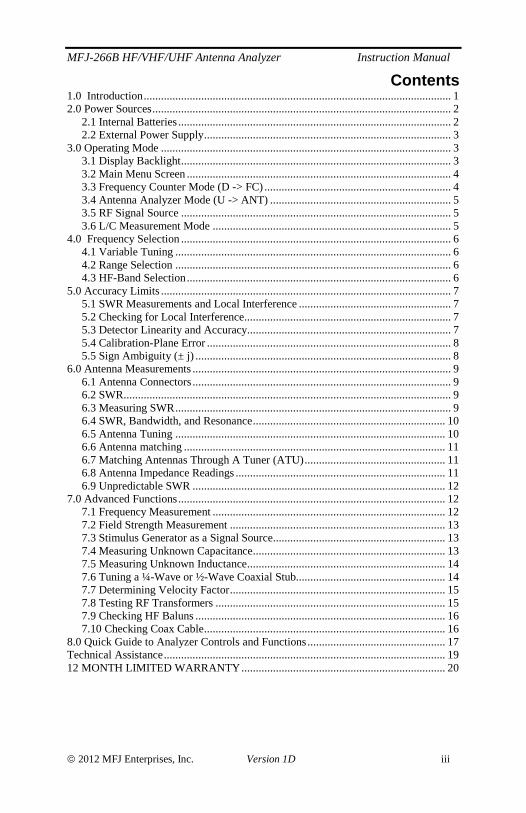
Contents 1.0 Introduction........................................................................................................... 1 2.0 Power Sources........................................................................................................ 2
2.1 Internal Batteries............................................................................................... 2 2.2 External Power Supply...................................................................................... 3
3.0 Operating Mode ..................................................................................................... 3 3.1 Display Backlight.............................................................................................. 3 3.2 Main Menu Screen ............................................................................................ 4 3.3 Frequency Counter Mode (D -> FC) ................................................................. 4 3.4 Antenna Analyzer Mode (U -> ANT) ............................................................... 5 3.5 RF Signal Source .............................................................................................. 5 3.6 L/C Measurement Mode ................................................................................... 5
4.0 Frequency Selection .............................................................................................. 6 4.1 Variable Tuning ................................................................................................ 6 4.2 Range Selection ................................................................................................ 6 4.3 HF-Band Selection............................................................................................ 6
5.0 Accuracy Limits ..................................................................................................... 7 5.1 SWR Measurements and Local Interference ..................................................... 7 5.2 Checking for Local Interference........................................................................ 7 5.3 Detector Linearity and Accuracy....................................................................... 7 5.4 Calibration-Plane Error ..................................................................................... 8 5.5 Sign Ambiguity (± j) ......................................................................................... 8
6.0 Antenna Measurements .......................................................................................... 9 6.1 Antenna Connectors.......................................................................................... 9 6.2 SWR.................................................................................................................. 9 6.3 Measuring SWR................................................................................................ 9 6.4 SWR, Bandwidth, and Resonance................................................................... 10 6.5 Antenna Tuning .............................................................................................. 10 6.6 Antenna matching ........................................................................................... 11 6.7 Matching Antennas Through A Tuner (ATU)................................................. 11 6.8 Antenna Impedance Readings ......................................................................... 11 6.9 Unpredictable SWR ........................................................................................ 12
7.0 Advanced Functions............................................................................................. 12 7.1 Frequency Measurement ................................................................................. 12 7.2 Field Strength Measurement ........................................................................... 13 7.3 Stimulus Generator as a Signal Source............................................................ 13 7.4 Measuring Unknown Capacitance................................................................... 13 7.5 Measuring Unknown Inductance..................................................................... 14 7.6 Tuning a ¼-Wave or ½-Wave Coaxial Stub.................................................... 14 7.7 Determining Velocity Factor........................................................................... 15 7.8 Testing RF Transformers ................................................................................ 15 7.9 Checking HF Baluns ....................................................................................... 16 7.10 Checking Coax Cable.................................................................................... 16
8.0 Quick Guide to Analyzer Controls and Functions................................................ 17 Technical Assistance.................................................................................................. 19 12 MONTH LIMITED WARRANTY....................................................................... 20

MFJ-266B HF/VHF/UHF Antenna Analyzer Instruction Manual
2012 MFJ Enterprises, Inc. Version 1D 1
1.0 INTRODUCTION Important: Read Section-2 before attempting to use your analyzer -- applying incorrect operating voltages could result in permanent damage! Also, never apply a DC voltage to the antenna connector.
General Description: The MFJ-266B is a self-contained handheld RF analyzer that performs the following diagnostic functions:
SWR (1:1 to 9.9:1) Complex Impedance (Z = R + jX) Impedance Magnitude (Z = ΩΩΩΩ) Capacitance (pF) Inductance (uH) Relative Field Strength (mV) Frequency (MHz)
The MFJ-266B also generates a 2-dBm RF signal that may be used to check receivers, networks, amplifiers, and antenna patterns. Operating range is:
HF: 1.5 - 71 MHz in six HF bands VHF: 85-185 MHz continuous coverage UHF: 300-490 MHz continuous coverage
A 10:1 vernier drive provides smooth tuning. Measurements are displayed on an easy-to-read LCD screen with optional backlighting. Power is supplied by internal AA cells or by a regulated 12-VDC external power source (not included). Weighing just over 1.3 pounds, the MFJ-266B package fits comfortably in one hand for convenient bench work or on-the-fly testing in the field. Operation is simple, but you will need to read the manual to learn all of the unit's features and functions. The more you know the more valuable it will become as a diagnostic tool.
MFJ-266B HF/VHF/UHF Antenna Analyzer Instruction Manual
2012 MFJ Enterprises, Inc. Version 1D 2
2.0 POWER SOURCES The MFJ-266B may be powered with internal AA batteries or with an external DC supply. To avoid needless damage and ensure top performance, please follow the guidelines below when choosing a voltage source.
2.1 Internal Batteries To access the jumpers and battery compartments, remove all four screws securing the analyzer's back cover and carefully open the case. To operate the MFJ-266B on batteries put the EXT PWR-BAT jumper on the PC board in the BAT position and install the batteries.
Battery power requires 4 (four) AA-size 1.5-volt alkaline cells. Batteries are installed in a fully encased 4-cell plastic trays mounted inside the analyzer enclosure. Slide the battery box covers sideways to unlatch, and then lift vertically to expose the cells.
Slide andLift
When replacing old batteries, be sure to follow the manufacturer's environmental guidelines for safe disposal. For longest battery life, always replace with a matched set of factory-fresh cells. The MFJ-266B will not charge batteries in the AA cell pack. Do not use rechargeable AA cells in the pack. The MFJ-266B can also hold an optional rechargeable 18650 battery. This battery is inserted into a holder that is at the bottom of the case. Disassemble the case as listed above and insert the battery into the holder making sure the polarity is correct. This battery is recharged from the external supply through a special charging circuit built into the MFJ-266B. Charging time is about 10 hours using the MFJ-1312B. The
18650 battery will only charge when the MFJ-266B is off. For charging the position of the EXT PWR-BAT jumper does not matter. It will charge in either position.
To switch between the AA cell pack and the rechargeable 18650 unplug the 3 pin header
from the AA cell pack and plug in the 3 pin header from the 18650 pack.
MFJ-266B HF/VHF/UHF Antenna Analyzer Instruction Manual
2012 MFJ Enterprises, Inc. Version 1D 3
2.2 External Power Supply
To operate the MFJ-266B on an external power supply open up the unit and move the EXT PWR-BAT jumper from to EXT PWR. The MFJ-266B will not run on external power and batteries at the same time.
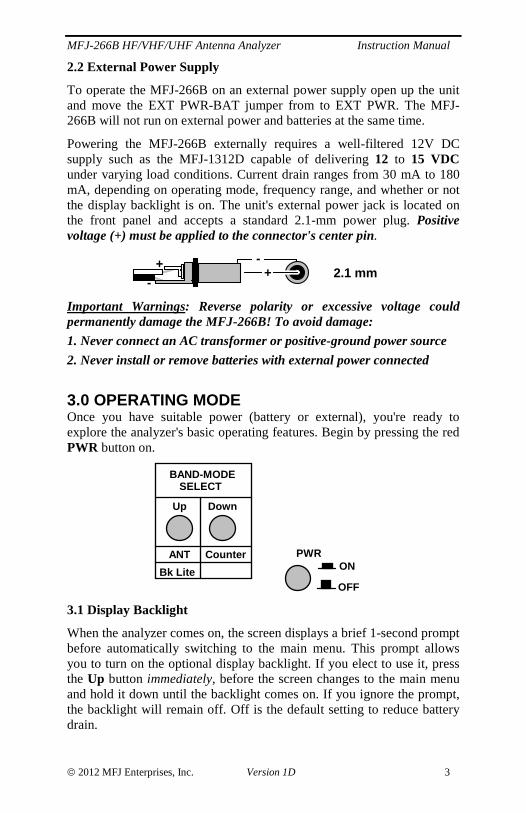
Powering the MFJ-266B externally requires a well-filtered 12V DC supply such as the MFJ-1312D capable of delivering 12 to 15 VDC under varying load conditions. Current drain ranges from 30 mA to 180 mA, depending on operating mode, frequency range, and whether or not the display backlight is on. The unit's external power jack is located on the front panel and accepts a standard 2.1-mm power plug. Positive voltage (+) must be applied to the connector's center pin.
+-
+-
2.1 mm
Important Warnings: Reverse polarity or excessive voltage could permanently damage the MFJ-266B! To avoid damage:
1. Never connect an AC transformer or positive-ground power source
2. Never install or remove batteries with external power connected
3.0 OPERATING MODE Once you have suitable power (battery or external), you're ready to explore the analyzer's basic operating features. Begin by pressing the red PWR button on.
BAND-MODESELECT
Up Down
ANT Counter
Bk Lite
PWRON
OFF
3.1 Display Backlight
When the analyzer comes on, the screen displays a brief 1-second prompt before automatically switching to the main menu. This prompt allows you to turn on the optional display backlight. If you elect to use it, press the Up button immediately, before the screen changes to the main menu and hold it down until the backlight comes on. If you ignore the prompt, the backlight will remain off. Off is the default setting to reduce battery drain.

MFJ-266B HF/VHF/UHF Antenna Analyzer Instruction Manual
2012 MFJ Enterprises, Inc. Version 1D 4
3.2 Main Menu Screen
The main menu screen has two purposes:
(1.) Power Supply Voltage: Appears on the right side of the screen. If it falls outside the 3.5 to 5V operating window of the battery packs, be sure to change batteries or make power supply adjustments.
(2.) Operating Mode Prompt: On the left side of the screen. This prompts you to select between the two primary operating modes (see below).
D >FC DC:12.00VU >ANT Analyzer
Supply Voltage"Down" for Counter
"Up" for Antenna Analyzer
(3.) (D >FC) Press the “Down” button to select Frequency Counter mode.
(4.) (U > ANT Analyzer) Press the “Up” button to select the Antenna Analyzer mode.
3.3 Frequency Counter Mode (D -> FC)
In this setup, the MFJ-266B functions as a 1-500 MHz frequency counter. Note that the BAND SELECT switch B must be "up" in the HF position for the counter mode to activate. If switch B is down, an error message will prompt you to change the band setting to HF.
A B
BAND SELECT
BAND A BHF X
VHFUHF
Counter X
UP
When a signal is applied to the Antenna jack, the frequency is displayed in MHz. Two gate speeds are available. The default gate speed is Fast (or Fg -- see the top right-hand side of the display). The fast gate provides 1-kHz resolution. The alternative gate speed is Slow (or Sg), which provides 100-Hz resolution. To change the gate speed:
(1.) For Fast Gate, press the UP button. (2.) For Slow Gate: press the DOWN button.
Fg f: 010.000 MHzREF FS: 100mV
Gate Speed Frequency Readout
Relative Field Strength
The Counter mode also provides relative Field Strength (REF FS). This feature is useful for conducting relative field-strength tests, estimating input levels to the counter, and detecting local signals that could impact SWR accuracy (see Section 7.2).

MFJ-266B HF/VHF/UHF Antenna Analyzer Instruction Manual
2012 MFJ Enterprises, Inc. Version 1D 5
3.4 Antenna Analyzer Mode (U -> ANT)
In this mode, the analyzer's built-in stimulus generator drives a bridge circuit and the unit functions as a network analyzer. The top line of the screen displays band selection (a single letter) and the operating frequency in MHz (see Section-4). The bottom line simultaneously displays complex impedance (Z = R+JX), impedance magnitude (Z = Ω), and SWR for any load connected to the antenna jack. Note that only SWR is displayed in the UHF operating range.
50+j 0 50 1.0Stimulus Frequency
Band (Frequency) Selection
SWR (1.0:1)10.000MHz D SWR
Impedance MagnitudeComplex Impedance 3.5 RF Signal Source
RF output from the MFJ-266B’s built-in stimulus generator is available at the ANT connector in Analyzer mode. This signal is a +2 dBm continuous carrier. When using the analyzer as a signal source, the operating range, band, and frequency are selected in the normal manner and will be displayed on the screen (see Frequency Selection, Section-4).
3.6 L/C Measurement Mode
The MFJ-266B may be used to measure the value of unknown capacitors and inductors. To measure L/C values, connect the device to be tested to the antenna jack and follow the procedure outlined below:
Measure Capacitance
Turn the analyzer off, then press and hold the Up button while turning PWR back on. The screen will display the value in pF along with the stimulus frequency being used for the measurement.
Measure Inductance
Turn the analyzer off, then press and hold the Down button while turning PWR back on. The display will show inductance in uH along with the stimulus frequency.
5.000MHz D C= 122 pF
Capacitance
Frequency Band
5.000MHz D L= 10.200 uH
Inductance
Frequency Band
5.000MHz D C=Xc>1.5k
Frequency Band
Reactance out of RangeChange Stimulus Frequency

MFJ-266B HF/VHF/UHF Antenna Analyzer Instruction Manual
2012 MFJ Enterprises, Inc. Version 1D 6
4.0 FREQUENCY SELECTION The MFJ-266B covers the HF region (1.5-71 MHz) in six bands, plus VHF (85-185 MHz) and UHF (300-490 MHz). Tuning and band-selection are electronically switched for high reliability.
4.1 Variable Tuning
The TUNE control uses an instrumentation-grade potentiometer with a 10:1 drive reduction to ensure gradual tuning on each band. Note that a mechanical lock is provided on the side of the TUNE knob assembly. The lock is used to prevent accidental changes once a desired frequency is set.
Dial Lock
TUNE
4.2 Range Selection
BAND SELECT buttons A and B are used to toggle between the HF, VHF , and UHF ranges. Follow the up/down position prompts shown in the table printed next to the buttons to select ranges.
A B
BAND SELECT
BAND A BHF X
VHFUHF
Counter X
X means the VHF/UHF switch can be in either position. Tuning is continuous in the VHF and UHF ranges. The frequency readout line of the display shows both the operating frequency in MHz and the letter of the selected range.
Band V: 85 to 185 MHz (FM, Airband, 2 Meters, 2-Way)
Band U: 300 to 490 MHz (Military, 70-cm, 2-way)
4.3 HF-Band Selection
The UP and DOWN buttons are used to step or scroll through a selection of six HF bands. To step up or down in one-band increments, quickly tap the appropriate switch to initiate each change. To scroll, press and hold the switch down. Most users find it easier to watch the letter designation for the desired band rather than watch the frequency display when making a selection:
A: 1.5 to 2.7 MHz (160 Meters) B: 2.5 to 4.8 MHz (80/75 Meters)
MFJ-266B HF/VHF/UHF Antenna Analyzer Instruction Manual
2012 MFJ Enterprises, Inc. Version 1D 7
C: 4.6 to 9.6 MHz (60,40 Meters) D: 8.5 to 18.7 MHz (30,20,17 Meters) E: 17.3 to 39 MHz (17,15,12,10 Meters) F: 38.7 to 71 MHz (6 Meters)
Before moving on to the next section, take time to review the MFJ-266B’s basic set-up procedures. Operation becomes second nature quickly, but should you need it, there’s a supplemental "quick guide" in the back for reference (Section 8.0). The remainder of the manual will focus on general instructions and helpful tips for making accurate measurements.
5.0 ACCURACY LIMITS The MFJ-266B will serve as your “eyes and ears” when working with RF systems, and it can deliver results that rival units costing thousands of dollars. However, all handheld analyzers share certain limitations, and being aware of them will help you to achieve more meaningful results.
5.1 SWR Measurements and Local Interference
The MFJ-266B (and other hand-helds) use a broadband diode detector that is open to receiving signals across the entire radio spectrum. Most of the time, the unit's built-in stimulus generator is powerful enough to overcome any lack of front-end selectivity and override stray pickup. However, a powerful transmitter located nearby could inject enough RF energy into the detector to disrupt readings. If this condition occurs, performance will become erratic and SWR readings may appear higher than they really are.
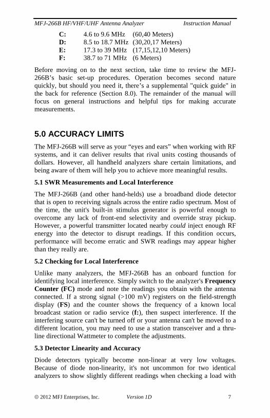
5.2 Checking for Local Interference
Unlike many analyzers, the MFJ-266B has an onboard function for identifying local interference. Simply switch to the analyzer's Frequency Counter (FC) mode and note the readings you obtain with the antenna connected. If a strong signal (>100 mV) registers on the field-strength display (FS) and the counter shows the frequency of a known local broadcast station or radio service (f: ), then suspect interference. If the interfering source can't be turned off or your antenna can't be moved to a different location, you may need to use a station transceiver and a thru-line directional Wattmeter to complete the adjustments.
5.3 Detector Linearity and Accuracy
Diode detectors typically become non-linear at very low voltages. Because of diode non-linearity, it's not uncommon for two identical analyzers to show slightly different readings when checking a load with
MFJ-266B HF/VHF/UHF Antenna Analyzer Instruction Manual
2012 MFJ Enterprises, Inc. Version 1D 8
very low SWR (or low RF-return voltage). For example, one analyzer may read 1.2:1 while another reads 1.1:1 when checking the same antenna. The MFJ-266B is electronically compensated to minimize detector error, but be aware of the potential for minor differences.
5.4 Calibration-Plane Error
The analyzer’s calibration plane is the point of reference where all measurements have the greatest accuracy (gain reference=0 dB, phase shift = 0-degrees). For basic hand-held units like the MFJ-266B, the calibration plane is fixed at the antenna connector. As such, any measurement made through a cable will displace the load from the calibration plane and introduce some amount of error. For SWR readings, error is mainly caused by losses in the cable. Specifically, SWR will read somewhat lower through a length of cable than with the analyzer connected directly to the direct load because the forward and reflected stimulus signals are attenuated in the feedline. The more loss there is in the cable, the greater the error. Most of the time, this inaccuracy isn’t a problem because the SWR you measure with the analyzer is the same SWR the radio will encounter when connected. However, if you wish to know the antenna’s actual feedpoint SWR for documentation purposes, the analyzer should be connected directly to the feed point through a short pigtail.
Calibration-plane error has a much more significant impact when attempting to measure impedance values because of phase rotation in the cable. In fact, impedance readings can swing dramatically, depending on the cable’s electrical length and the severity of the load’s mismatch with reference to 50 Ohms. For accurate impedance data, always connect the analyzer directly to the antenna or device you’re testing using the shortest lead possible.
5.5 Sign Ambiguity (± j)
Most hand-held analyzers (including the MFJ-266B) lack the processing capability to calculate the reactance sign for complex impedance (Z = R ± j ). By default, the MFJ-266B displays a plus sign (+ j) between the resistive and reactive values, but this sign is merely a placeholder and not a calculated data point. Although the analyzer’s processor can’t calculate sign, it can often be determined with a small adjustment of the TUNE control. To determine sign, TUNE the analyzer up-frequency slightly --
(1.) If reactance decreases, the sign is likely to be ( - ) and the reactance capacitive (XC).
(2.) If reactance increases, the sign is likely to be ( + ) and the reactance inductive (XL).
MFJ-266B HF/VHF/UHF Antenna Analyzer Instruction Manual
2012 MFJ Enterprises, Inc. Version 1D 9
6.0 ANTENNA MEASUREMENTS Excellent tutorials are available in ARRL Handbooks and other League antenna publications to help you master the art and science of constructing and adjusting effective antenna systems. Informative introductory material may also be found on line, but choose carefully. Not all web material is well edited or accurate (especially items discussed in chat rooms and forums). Here are some general guidelines to help you get started.
6.1 Antenna Connectors
The MFJ-266B uses a type-N female (or NF) connector to ensure reliable signal connectivity up to 500 MHz. It also comes with a SO-239-female to N-male (UHF-NM) adapter for transitioning to popular PL-259 connectors. When purchasing additional adapters, look for N-male rather than UHF transitions. Stacking multiple adapters together places unnecessary stress the analyzer’s N connector and increases the possibility of measurement error. Avoid using PL-259 connectors above 2 Meters because they may contribute significant mismatch to your measurements. Finally, when installing N-male connectors on patch cables and feedlines, pay close attention to pin depth. If the tip of the connector pin extends more than a few mils above the surrounding contact fingers, the pin shoulder could damage the analyzer's NF connector.
6.2 SWR
Standing Wave Ratio (SWR), sometimes referred to as VSWR, is the most widely used format for checking tuning error and impedance mismatch between antennas and radios. The MFJ-266B is calibrated to work on the 50-Ohm impedance standard used by amateur and commercial two-way equipment (Zo=50). Unless a different cable impedance is specified by the antenna designer for matching purposes, always use 50-Ohm cable of known quality when making up transmission lines and patch cables.
WARNING: Never apply external dc voltages or strong RF signals to the analyzer’s antenna connector or permanent damage will result. Also, never connect the output of a transmitter to your analyzer.
6.3 Measuring SWR
Here is the recommended procedure for the checking antenna SWR with the MFJ-266B:
(1.) Turn the unit ON and select the ANT Analyzer function (Section-3).
MFJ-266B HF/VHF/UHF Antenna Analyzer Instruction Manual
2012 MFJ Enterprises, Inc. Version 1D 10
(2.) Select the desired Range, Band, and Frequency (Section-4).
(3.) Connect the antenna to the analyzer (Antenna connector)*.
(4.) Rotate the Tune knob to find the lowest SWR reading and write it down.
(5.) Rotate Tune to either side of minimum SWR and note the 2:1 SWR points.
*When testing large ungrounded antenna systems such as HF dipoles, momentarily short the feedline center pin to ground to bleed off static buildup before connecting to the analyzer.
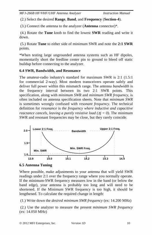
6.4 SWR, Bandwidth, and Resonance
The amateur-radio industry's standard for maximum SWR is 2:1 (1.5:1 for commercial 2-way). Most modern transceivers operate safely and deliver full power within this mismatch range. The antenna bandwidth is the frequency interval between its two 2:1 SWR points. This specification, along with minimum SWR and minimum SWR frequency, is often included on antenna specification sheets. Note that minimum SWR is sometimes wrongly confused with resonant frequency. The technical definition for resonance is the frequency where inductive and capacitive reactance cancels, leaving a purely resistive load (±j = 0). The minimum SWR and resonant frequencies may be close, but they rarely coincide.
13.9 14.0 14.1 14.2 14.3 14.4
1.5
2.0
1.0
Min. SWR Freq.
BandwidthLower 2:1 Freq. Upper 2:1 Freq.
Min. SWR
6.5 Antenna Tuning
Where possible, make adjustments to your antenna that will yield SWR readings under 2:1 over the frequency range where you normally operate. If the minimum-SWR frequency measures low in the band (or below the band edge), your antenna is probably too long and will need to be shortened. If the Minimum SWR frequency is too high, it should be lengthened. To calculate the required change in length:
(1.) Write down the desired minimum SWR frequency (ex: 14.200 MHz)
(2.) Use the analyzer to measure the present minimum SWR frequency (ex: 14.050 MHz)

MFJ-266B HF/VHF/UHF Antenna Analyzer Instruction Manual
2012 MFJ Enterprises, Inc. Version 1D 11
(3.) Divide the present frequency by the desired frequency (ex 14.050 ÷ 14.200 = .989)
(4.) Multiply the present length by the result (33.3 feet x .989 = 32.94 feet)
Note that this formula applies to full-sized antennas, but not to elements shortened by coils, traps, or capacitive hats.
6.6 Antenna matching
If your antenna doesn’t exhibit 1:1 SWR at the minimum SWR frequency, then some mismatch is present relative to 50-Ohms. For simple dipoles and ground-independent verticals, mounting height above ground may be the primary cause. Generally, it’s best to ignore SWR readings under 2:1 and mount these antennas as high as possible where they’ll perform best. For antennas that feature adjustable matching networks (Yagis etc), SWR can usually be improved by following the manufacturer’s antenna setup instructions. Note that matching and tuning settings may interact, so readjustment of both the antenna’s element length and matching network may be needed to obtain best results.
6.7 Matching Antennas Through A Tuner (ATU)
If your antenna can’t be tuned or matched to an acceptable SWR level by making physical adjustments, then an external antenna tuner (ATU) should be installed. The MFJ-266B may be used in conjunction with the tuner to make adjustments without the need to transmit test signals over air. Simply connect the analyzer to the tuner input (radio side) through a short patch cable. Select the Analyzer mode, set up the Band, and Tune for the desired frequency of operation. Then, adjust the antenna-tuner's controls following the manufacturer's recommendations until SWR approaches 1:1. Remove the analyzer, reconnect the radio, and the load will be pre-matched to the radio's 50-Ohm operating impedance.
6.8 Antenna Impedance Readings
The MFJ-266B displays complex impedance and impedance magnitude readings on the same screen with the SWR reading. However, when measuring through coax, remember that the impedance readings are phase-shifted values appearing at your end of the cable and not the actual feedpoint impedance of the antenna itself (Section-5.4). As a “work-around” strategy, it’s possible to measure the antenna’s actual impedance remotely if the feedline is cut to an exact electrical half wavelength. In a half-wavelength line, the phase shift is a full 360 degrees, which electrically rotates the analyzer’s calibration plane back into alignment with the load. However, this strategy only works at one frequency and errors compound quickly if your cable is multiple half-wavelengths long. As a practical matter, unless you have an advanced working knowledge

MFJ-266B HF/VHF/UHF Antenna Analyzer Instruction Manual
2012 MFJ Enterprises, Inc. Version 1D 12
of transmission-lines, Smith charts, and impedance matching theory, it’s best to ignore impedances and rely on SWR for routine antenna-system adjustments.
6.9 Unpredictable SWR
A change in feedline length shouldn't shift your antenna's minimum-SWR frequency or have much impact on the SWR readings. If it does, suspect a significant mismatch between the antenna and coax, or more likely, poor isolation between the feedline and the antenna. Isolation problems typically occur when unbalanced coax line is connected directly to a balanced element such as a dipole or a loop, and the outer surface of the coax shield literally becomes a part of the antenna. If the length of the shield happens to presents a low impedance path, it can load the element significantly and shift the minimum-SWR frequency unpredictably. It will also introduce needless mismatch, divert transmitted RF back toward the operating position, cause RFI problems in the residence, and increase unwanted noise pickup in receive mode. The best way to decouple the outer surface of the shield from the antenna element is with a balun. Current-type baluns work best because they have higher power-handling capability and less loss than other types. An effective current balun could be as simple as a few loops of coax taped together at the feedpoint, but for best common-mode rejection, a Guanella-style balun wound on a ferrite core is recommended.
7.0 ADVANCED FUNCTIONS Here are some of the MFJ-266B advance functions. Note that some of these procedures involve connecting component leads to the unit's N connector. For these connections, we suggest making up a very short N-male coaxial pigtail or obtaining a type-N dual binding post adapter to prevent damage the center-contact of the analyzer connector.
7.1 Frequency Measurement
The MFJ-266B features a precision counter that accurately measures the frequency of RF signals between 1 and 500 MHz with up to 100-Hz resolution (see Section-3.3 for setup). To conduct measurements, connect your signal source to the unit’s antenna jack. The counter will typically lock onto any signal 30 mv (-20 dBm) or stronger, with an upper signal measurement limitation of 1 volt (or +10 dBm). Any input signal exceeding +10 dBm automatically triggers a Danger – High FS warning on the analyzer display (high field strength). This is a notification to reduce the signal level as quickly as possible.
Warning: Avoid connecting any external RF source more powerful than 10 dBm (or 10 mW) to the analyzer's antenna connector.
MFJ-266B HF/VHF/UHF Antenna Analyzer Instruction Manual
2012 MFJ Enterprises, Inc. Version 1D 13
7.2 Field Strength Measurement
The field strength function works in conjunction with the counter mode to display Relative RF-input Level (REF FS). Any external antenna that yields a usable signal level may be connected to the analyzer’s antenna jack to serve as a pickup device. The usable signal range is around 30-dB (30-mV to 1-V rms). Note that the display reading is a RMS level taken directly from the MCU detector, so it must be multiplied by 1.414 to obtain a peak AC value (V-rms x 1.414 = V-p, conversely V-p x .707 = V-rms). Also, despite the display's 0.1 mV resolution, readings will be approximations rather than precise values because of detector non-linearity.
The Danger - High FS display warning means a dangerously strong signal is being applied and the level should be reduced immediately. Also, interference greater than 100 mV will almost certainly cause inaccurate SWR measurements when in Analyzer mode.
7.3 Stimulus Generator as a Signal Source
When operated in Analyzer mode, the MFJ-266B generates a +2 dBm CW carrier (2 mW). See section 3.6 for setup procedures. Output will vary slightly, depending on frequency and operating voltage, but typically holds to within 1-2 dB of the rated power level over the analyzer's frequency range. Second-harmonic suppression averages -20 dBc. A quarter-wave stub or low-pass filter may be installed if greater harmonic suppression is required for a specific application. Frequency stability and carrier purity are sufficient for testing filters, mixers, low-power amplifier stages, and for checking antenna patterns when a range antenna is connected to the analyzer output. The stimulus generator may also be used for producing lower-level signals with a suitable precision RF attenuator installed in line. When connecting the generator directly to active circuitry, always insert a coupling capacitor to prevent DC voltages from back-feeding into the bridge circuit and destroying the detector diodes. Also, avoid connecting the stimulus signal directly to sensitive preamps or receiver circuits that could be damaged by an un-attenuated 2-mW signal.
7.4 Measuring Unknown Capacitance
To measure capacitance, connect the unknown component to the Antenna connector (usable range is from approximately 15 pF to 1200 pF). To enter the Capacitance mode, begin with the analyzer turned off, then press and hold the Up button while pressing the PWR switch (see Section 3.6). The screen will display the approximate value of the unknown capacitor in pF along with the stimulus frequency where the measurement is being made. Note that you will not have full control over stimulus-frequency Band selection in this mode. Of the bands offered,

MFJ-266B HF/VHF/UHF Antenna Analyzer Instruction Manual
2012 MFJ Enterprises, Inc. Version 1D 14
the best accuracy is typically obtained on Band C, which may be selected using the Up/Down switches. Note that any capacitor and lead combination that approaches self-resonance at the stimulus frequency will trigger the C = Xc >1.5KΩΩΩΩ message and will be un-measurable. Attempt to re-measure at a lower frequency.
7.5 Measuring Unknown Inductance
To measure inductance, connect the unknown component to the Antenna connector. To enter the Inductance mode, begin with the analyzer turned off, then press and hold the Down button while pressing the PWR switch on (see Section 3.6). The screen will display the approximate value of the unknown inductor in uH along with the stimulus frequency where the measurement is being made. You will not have full control over the stimulus-frequency Band selection and the best accuracy is usually obtained on Band B or C (selected using the Up/Down switches). Note that any inductor approaching self-resonance at the stimulus frequency will trigger the L = XL >1.5KΩΩΩΩ message and will be un-measurable. Try to re-measure at a lower frequency.
7.6 Tuning a ¼-Wave or ½-Wave Coaxial Stub
To accurately tune a coaxial stub, begin by calculating the free-space length at the stub's intended operating frequency:
For 1/4-λ in inches = 2951 ÷ MHz
For 1/4-λ in feet = 246 ÷ MHz
For 1/2-λ in inches = 5902 ÷ MHz
For 1/2-λ In feet = 492 ÷ MHz
Next, multiply the free-space length times your cable's velocity factor. Finally, add at least 10% to this length for a margin of error (better too long than too short). Cut the cable to this initial length. Connect one end of the cable to the analyzer's Antenna connector. For a 1/4-λ stub, leave the far end open. For a 1/2-λ stub, short the far end. Next:
(1.) Set the MFJ-266B to Analyzer mode (Section-3)
(2.) Initially, set the Range, Band, and Tune for the desired stub frequency (Section-4)
(3.) *Tune down in frequency to find lowest impedance-magnitude reading (the load is a short).
(4.) Write your measured frequency down.
(5.) Divide the measured frequency by the desired stub frequency to obtain a correction factor
(6.) Multiply the present stub length by the correction factor to get the desired stub length.

MFJ-266B HF/VHF/UHF Antenna Analyzer Instruction Manual
2012 MFJ Enterprises, Inc. Version 1D 15
(7.) Re-cut the cable to that length.
*Note that the impedance value may not drop to zero, but it will begin to increase again as you continue to tune past the null. If the null reading is broad, choose a frequency at the center.
7.7 Determining Velocity Factor
If you have coax cable with an unknown velocity factor, you can determine it quickly using the following procedure:
(1.) Set the MFJ-266B up in Analyzer mode (Section-3)
(2.) Set the Range to HF and the Band to E (Section-4)
(3.) Make a 1/4-λ stub from 9 feet of the unknown cable and connect it to the analyzer (open end)
(4.) Rotate Tune for minimum impedance magnitude reading. Write down the frequency (MHz)
(5.) Divide 246 by this frequency to find the free-space 1/4-λ wavelength in feet (L = 246 ÷ f MHz)
(6.) Divide 9 (actual length) by free-space 1/4-λ wavelength to get the Velocity Factor (VF =9 ÷ L)
Note that there is nothing magical about the 9-foot stub length, other than it falls conveniently within the limits of Band E’s tuning range. Other lengths could be used. Shorter stubs will yield poorer accuracy and long ones may needlessly waste useful cable.
7.8 Testing RF Transformers
Broadband HF-matching transformers wound for the 12.5 to 200 Ohm range may be tested using the MFJ-266B. Connect the 50-Ohm (primary) side to the analyzer connector using a short pigtail and attach the appropriate resistive load across the secondary side (always use a non-inductive resistor). Next:
MJ-266
Load
Transformer
(1.) Set the MFJ-266B up in Analyzer mode (Section-3)
(2.) Set the Band Select to HF and the Band-Mode to the desired frequency range (Section-4)
(3.) Rotate Tune across the frequency range and note SWR. Change bands, as needed.
MFJ-266B HF/VHF/UHF Antenna Analyzer Instruction Manual
2012 MFJ Enterprises, Inc. Version 1D 16
At the low and high ends of the transformer's frequency response range, SWR and reactance will climb to unacceptable levels (< 1.2:1 is ideal). HF, VHF, and UHF tuned transmission-line transformers may be tested in similar fashion by connecting one end directly to the analyzer and terminating the far end. However, only precision RF terminations with known impedance characteristics should be used above 50 MHz. Set up the analyzer for the desired range and sweep the band of interest using the Tune control. Transmission-line transformers are “frequency specific” and have much more limited frequency response.
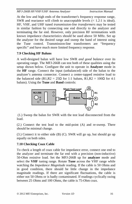
7.9 Checking HF Baluns
A well-designed balun will have low SWR and good balance over its operating range. The MFJ-266B can test both of these qualities using the setup shown below. Configure the unit to operate in Analyzer mode in the HF range. Connect the input (unbalanced) side of the balun to the analyzer’s antenna connector. Connect a center-tapped resistive load to the balanced side (R1,R2 = 25Ω for 1:1 baluns, R1,R2 = 100Ω for 4:1 baluns). Using the Tune and Band controls:
B
C
Balun
MJ-266
A
Short Test Lead
R1
R2
(1.) Sweep the balun for SWR with the test lead disconnected from the load.
(2.) Connect the test lead to the mid-point (A) and re-sweep. There should be minimal change.
(3.) Connect it to either side (B) (C). SWR will go up, but should go up equally on both sides.
7.10 Checking Coax Cable
To check a length of coax cable for impedance error, connect one end to the analyzer and terminate the far end with a precision (non-inductive) 50-Ohm resistive load. Set the MFJ-266B up for analyzer mode and select the VHF tuning range. Rotate Tune across the VHF range while watching the Impedance Magnitude reading. If the cable is 50 Ohms and in good condition, there should be little change in the impedance magnitude readings. If there are significant fluctuations, the cable is either not 50 Ohms or is badly contaminated. If readings cyclically swing between 25 Ohms and 100 Ohms, the cable is 75-Ohm coax.
MFJ-266B HF/VHF/UHF Antenna Analyzer Instruction Manual
2012 MFJ Enterprises, Inc. Version 1D 17
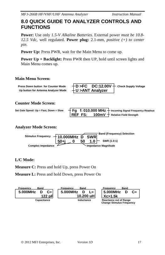
8.0 QUICK GUIDE TO ANALYZER CONTROLS AND FUNCTIONS
Power: Use only 1.5-V Alkaline Batteries. External power must be 10.8-12.5 Vdc, well regulated. Power plug: 2.1-mm, positive (+) to center pin.
Power Up: Press PWR, wait for the Main Menu to come up.
Power Up + Backlight: Press PWR then UP, hold until screen lights and Main Menu comes up.
Main Menu Screen:
D >FC DC:12.00VU >ANT Analyzer
Check Supply Voltage Press Down button for Counter Mode
Up button for Antenna Analyzer Mode
Counter Mode Screen:
Fg f: 010.000 MHzREF FS: 100mV
Set Gate Speed: Up = Fast, Down = Slow Incoming Signal Frequency Readout
Relative Field Strength
Analyzer Mode Screen:
50+j 0 50 1.0Stimulus Frequency
Band (Frequency) Selection
SWR (1.0:1)10.000MHz D SWR
Impedance MagnitudeComplex Impedance
L/C Mode:
Measure C: Press and hold Up, press Power On
Measure L: Press and hold Down, press Power On
5.000MHz D C= 122 pF
Capacitance
Frequency Band
5.000MHz D L= 10.200 uH
Inductance
Frequency Band
5.000MHz D C=Xc>1.5k
Frequency Band
Reactance out of RangeChange Stimulus Frequency
MFJ-266B HF/VHF/UHF Antenna Analyzer Instruction Manual
2012 MFJ Enterprises, Inc. Version 1D 18
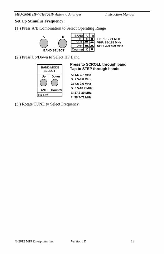
Set Up Stimulus Frequency:
(1.) Press A/B Combination to Select Operating Range
A B
BAND SELECT
BAND A BHF X
VHFUHF
Counter X
HF: 1.5 - 71 MHz VHF: 85-185 MHzUHF: 300-490 MHz
(2.) Press Up/Down to Select HF Band
BAND-MODESELECT
Up Down
ANT Counter
Bk Lite
Tap to STEP through bandsPress to SCROLL through bands
A: 1.5-2.7 MHz
B: 2.5-4.8 MHz
C: 4.6-9.6 MHz
D: 8.5-18.7 MHz
E: 17.3-39 MHz
F: 38.7-71 MHz
(3.) Rotate TUNE to Select Frequency
MFJ-266B HF/VHF/UHF Antenna Analyzer Instruction Manual
2012 MFJ Enterprises, Inc. Version 1D 19
Technical Assistance If you have any problem with this unit first check the appropriate section of this manual. If the manual does not reference your problem or your problem is not solved by reading the manual, you may call MFJ Technical Service at 662-323-0549 or the MFJ Factory at 662-323-5869. You will be best helped if you have your unit, manual and all information on your station handy so you can answer any questions the technicians may ask.
You can also send questions by mail to MFJ Enterprises, Inc., 300 Industrial Park Road, Starkville, MS 39759; by facsimile (FAX) to 662-323-6551; or by email to [email protected]. Send a complete description of your problem, an explanation of exactly how you are using your unit, and a complete description of your station. Also include the firmware version number of your unit.

MFJ-266B HF/VHF/UHF Antenna Analyzer Instruction Manual
12 MONTH LIMITED WARRANTY MFJ Enterprises, Inc. Warrants to the original owner of this product, if manufactured by MFJ Enterprises, Inc. and purchased from an authorized dealer or directly from MFJ Enterprises, Inc. to be free from defects in material and workmanship for a period of 12 months from date of purchase provided the following terms of this warranty are satisfied.
1. The purchaser must retain the dated proof-of-purchase (bill of sale, canceled check, credit card or money order receipt, etc.) describing the product to establish the validity of the warranty claim and submit the original or machine reproduction of such proof-of-purchase to MFJ Enterprises, Inc. at the time of warranty service. MFJ Enterprises, Inc. shall have the discretion to deny warranty without dated proof-of-purchase. Any evidence of alteration, erasure, or forgery shall be cause to void any and all warranty terms immediately.
2. MFJ Enterprises, Inc. agrees to repair or replace at MFJ’s option without charge to the original owner any defective product under warranty, provided the product is returned postage prepaid to MFJ Enterprises, Inc. with a personal check, cashiers check, or money order for $12.00 covering postage and handling .
3. MFJ Enterprises, Inc. will supply replacement parts free of charge for any MFJ product under warranty upon request. A dated proof-of-purchase and an $8.00 personal check, cashiers check, or money order must be provided to cover postage and handling.
4. This warranty is NOT void for owners who attempt to repair defective units. Technical consultation is available by calling (662) 323-5869.
5. This warranty does not apply to kits sold by or manufactured by MFJ Enterprises, Inc.
6. Wired and tested PC board products are covered by this warranty provided only the wired and tested PC board product is returned. Wired and tested PC boards installed in the owner’s cabinet or connected to switches, jacks, or cables, etc. sent to MFJ Enterprises, Inc. will be returned at the owner’s expense unrepaired.
7. Under no circumstances is MFJ Enterprises, Inc. liable for consequential damages to person or property by the use of any MFJ products.
8. Out-of-warranty Service: MFJ Enterprises, Inc. will repair any out-of-warranty product provided the unit is shipped prepaid. All repaired units will be shipped COD to the owner. Repair charges will be added to the COD fee unless other arrangements are made.
9. This warranty is given in lieu of any other warranty expressed or implied.
10. MFJ Enterprises, Inc. reserves the right to make changes or improvements in design or manufacture without incurring any obligation to install such changes upon any of the products previously manufactured.
11. All MFJ products to be serviced in-warranty or out-of-warranty should be addressed to MFJ Enterprises, Inc., 300 Industrial Park Road, Starkville, Mississippi 39759, USA and must be accompanied by a letter describing the problem in detail along with a copy of your dated proof-of-purchase.
12. This warranty gives you specific rights, and you may also have other rights, which vary from state to state.

MFJ-266 ManualVersion 1D300 Industrial Park Road
Starkville, MS 39759