Embed Size (px)
Citation preview

Design and Implementation Guide
ii © 2016 Juniper Networks, Inc.
Juniper Networks Metro Ethernet Design Guide
August 2016

Design and Implementation Guide
© 2016 Juniper Networks, Inc. iii
Juniper Networks, Inc. 1133 Innovation Way Sunnyvale, California 94089 USA 408-745-2000 www.juniper.net
Copyright © 2016, Juniper Networks, Inc. All rights reserved.

Design and Implementation Guide
iv © 2016 Juniper Networks, Inc.
Table of Contents
Chapter 1 Introduction ............................................................................................................... 1
Using MPLS with Metro Ethernet ........................................................................................... 1
Metro Ethernet Solutions ......................................................................................................... 2
Chapter 2 Metro Ethernet Overview ......................................................................................... 3
Metro Ethernet Service Types ..................................................................................................... 5
Carrier Ethernet Overview........................................................................................................... 5
Carrier Ethernet Certification ................................................................................................... 6
Chapter 3 Architecture Overview .............................................................................................. 7
Juniper Networks Portfolio for Metro Ethernet Networks .......................................................... 7
ACX Series Routers in the Access Segment ............................................................................ 7
ACX Series Routers in the Metro Aggregation Segment ........................................................ 7
MX Series Routers in the Metro Aggregation and Core Segments ......................................... 8
PTX Series Routers in the Core Segment ................................................................................ 8
Junos Space Platform ............................................................................................................... 8
Metro Ethernet as Part of Access and Aggregation ..................................................................... 9
Ethernet Bridging as Metro Ethernet Transport ........................................................................ 10
Chapter 4 Metro Ethernet Scenarios ........................................................................................ 13
Layer 2 Business Access ........................................................................................................... 13
Wholesale Mobile Backhaul ...................................................................................................... 15
Wholesale MBH Deployment Options .................................................................................. 17
Wholesale MBH Deployment with Dual E-Line Services and Layer 3 CPE ........................ 18
Wholesale MBH Deployment with Dual E-Line Services and Layer 2 CPE ........................ 19
Wholesale MBH Deployment with E-LAN/E-Tree Services ................................................ 20
Layer 3 Business Access and DIA Service Profile.................................................................... 22
Residential Aggregation Use Case ............................................................................................ 25
Enabling EVC for Residential Internet Access ...................................................................... 26

Design and Implementation Guide
© 2016 Juniper Networks, Inc. v
Enabling Multicast Delivery in the MAN ................................................................................. 29
Enabling Connectivity for the Inbound OAM of the CPE/STB............................................. 33
Chapter 5 Enabling Metro Ethernet Services on Junos Platforms.......................................... 35
Design Considerations, Definitions, and Prerequisites ............................................................. 35
Deployment Topologies ............................................................................................................ 36
Chapter 6 Metro Ethernet Nodes and Functions ..................................................................... 39
Metro Access Nodes and Functions ....................................................................................... 39
Metro Aggregation Nodes and Functions .............................................................................. 40
Chapter 7 Enabling Metro EVC in Junos ................................................................................ 43
Establishing End-to-End EVCs .............................................................................................. 47
S-VLAN Translation of the EVC between Ethernet Rings .............................................. 48
Ethernet Bridging verses MPLS in the Access Node ............................................................. 50
Specifics of VPLS Deployments in the MAN ....................................................................... 51
BGP Versus LDP Signaling .............................................................................................. 51
End-to-End EVC Stitching with VPLS Routing Instance (Option 1)............................... 52
End-to-End EVC Stitching with VPLS RI (Option 2) ...................................................... 54
Recommendations for VPLS Routing Instances and VSI Deployment in the MAN ....... 56
Summary of the VPLS Flavors Supported by Junos Platforms ............................................. 57
MPLS AN with Multiple UNIs per Customer ....................................................................... 58
Using LT-Interface at VPLS Hub to Terminate Spoke’s PW........................................... 59
VPLS Light Deployment Options on ACX Series Routers .............................................. 60
Terminating Multiple Spokes from a Single AN into the Same Mesh Group .................. 60

Design and Implementation Guide
vi © 2016 Juniper Networks, Inc.
Chapter 8 Tunneling L2CP Traffic .......................................................................................... 63
MX Series Router as VPLS or MPLS Access Node ................................................................. 65
ACX Router as Ethernet Access Node ...................................................................................... 65
ACX Router as MPLS Access Node ......................................................................................... 65
Chapter 9 CoS Planning for Metro Ethernet Services ............................................................. 67
General Notes about CoS Management on Junos Platforms ..................................................... 67
Customer Frame Classification and Scheduling in MAN................................................. 70
Customer L2CP Frames Classification ............................................................................. 73
Chapter 10 Bandwidth Profile for Metro-E Services ................................................................ 75
Defining Bandwidth Profile ...................................................................................................... 75
Coupling Flag and Color Mode Consideration.......................................................................... 76
Bandwidth parameters: CIR, EIR, CBS and EBS ..................................................................... 77
Supported BWP Models and Platforms ................................................................................. 78
Chapter 11 Infrastructure Security Design and Considerations ................................................ 79
Security Considerations ............................................................................................................. 79
Protecting Against Unauthorized Access .................................................................................. 80
Protecting Against Hijacking Threats ....................................................................................... 80
Control Plane DDOS Protection ............................................................................................ 80
CFM Traffic Policing ............................................................................................................. 81
Restricting the Size of MAC Learning Tables ....................................................................... 81
Protecting Against Layer 2 Loops ............................................................................................. 81
Infrastructure Triggered Broadcast Storms ............................................................................ 82
Broadcast Storms in VPLS Architectures ......................................................................... 82
Broadcast Storms in a Hybrid Architectures .................................................................... 82

Design and Implementation Guide
© 2016 Juniper Networks, Inc. vii
Customer-Triggered Broadcast Storms .................................................................................. 82
Layer 2 Storm Control............................................................................................................ 84
Control Plane Protection During a Layer 2 Storm ................................................................. 85
MAC Move Control ............................................................................................................... 85
Chapter 12 Providing Resiliency in Metro Ethernet Networks ................................................. 87
Resilient Metro Ethernet Networks ........................................................................................... 87
Pseudowire Redundancy for T-LDP PW .................................................................................. 87
Protecting Dual-homed CPE with MC-LAG ............................................................................ 90
Chapter 13 Protection with IEEE G.8032 Protocol ................................................................... 93
Using G.8032 for Native Ethernet Access Segments ................................................................ 93
Using G.8032 with Ethernet-to-VPLS Stitching ....................................................................... 94
Remote End Failure Detection Signaling via LFM ................................................................... 95
Pseudowire Tail-end Protection for Metro PE to PE Failure ................................................. 97
Chapter 14 OAM ....................................................................................................................... 99
Ethernet OAM ......................................................................................................................... 100
Intra-segment OAM ................................................................................................................. 102
Intersegment OAM .................................................................................................................. 103
Chapter 15 Inventory of the Network Services ....................................................................... 105
Chapter 16 Deployment Scenarios and Recommendations ..................................................... 109
Deployment Scenarios ............................................................................................................. 109
EP-LINE Deployment Scenarios ............................................................................................. 110
EP-LINE with a Native Ethernet Segment ........................................................................... 111
EP-LINE with End-to-End MPLS PW................................................................................. 113
EP-LINE with Ethernet to MPLS PW Stitching .................................................................. 115
EP-LINE with Ethernet to VPLS Termination .................................................................... 117
EVP-LINE Deployment Scenarios .......................................................................................... 119
EVP-LINE within a Native Ethernet Segment ..................................................................... 120
EVP-LINE with End-to-End MPLS PW .............................................................................. 122

Design and Implementation Guide
viii © 2016 Juniper Networks, Inc.
EVP-LINE with Ethernet to MPLS PW Stitching ............................................................... 124
EVP-LINE with Carrier Ethernet to VPLS Termination ..................................................... 126
EP-LAN Deployment Scenarios .............................................................................................. 128
EP-LAN within a Native Ethernet Segment ........................................................................ 128
EP-LAN with MPLS PW to VPLS Termination ................................................................. 130
EP-LAN with Ethernet to VPLS Termination ..................................................................... 132
EVP-LAN Deployment Scenarios ........................................................................................... 134
EVP-LAN within Pure Ethernet Segment ............................................................................ 135
EVP-LAN with MPLS PW to VPLS Termination............................................................... 136
EVP-LAN with Ethernet to VPLS Termination .................................................................. 138
EP-ACCESS Deployment Scenarios ....................................................................................... 141
EP-ACCESS within Native Ethernet Segment .................................................................... 141
EP-ACCESS with End-to-End MPLS PW .......................................................................... 143
EP-ACCESS with Ethernet to MPLS PW Stitching ............................................................ 145
EP-ACCESS with Ethernet to VPLS Stitching .................................................................... 146
EVP-ACCESS Deployment Scenarios .................................................................................... 149
EVP-ACCESS within a Pure Carrier Ethernet Segment ...................................................... 149
EVP-ACCESS with End-to-End MPLS PW ........................................................................ 151
EVP-ACCESS with Ethernet to MPLS PW Stitching ......................................................... 153
EVP-ACCESS with Ethernet to VPLS Stitching ................................................................. 154
EP-TREE Deployment Scenarios ............................................................................................ 157
EP-TREE with End-to-End VPLS ....................................................................................... 158
LDP Signaling ................................................................................................................. 158
BGP Signaling ................................................................................................................ 158
EP-TREE with Leaf PW to VPLS Termination ................................................................... 160
LDP Signaling ................................................................................................................. 161
BGP Signaling ................................................................................................................ 161

Design and Implementation Guide
© 2016 Juniper Networks, Inc. ix
EP-TREE with Root PW into VPLS Termination ............................................................... 162
LDP Signaling ................................................................................................................. 163
BGP Signaling ................................................................................................................ 163
EVP-TREE Deployment Scenarios ......................................................................................... 164
EVP-TREE with End-to-End VPLS .................................................................................... 164
EVP-TREE with Leaf PW to VPLS Termination ................................................................ 166
EVP-TREE with Root PW into VPLS Termination ............................................................ 168
S-VLAN Normalization .......................................................................................................... 170
C-VLAN Translation ............................................................................................................... 172


Design and Implementation Guide
© 2016 Juniper Networks, Inc. 1
Chapter 1 Introduction
Overview of the Metro Ethernet Solutions Service providers use Metro Ethernet to provide Layer 2 Ethernet connections between customer sites in metro area networks. Driven by its relative simplicity, high bandwidth, and low-cost switches, Ethernet has become the transport technology of choice in metro area networks.
There are numerous applications that require pure Layer 2 connectivity in the metro area network (MAN) for providing simple point-to-point, point-to-multipoint, or multipoint-to-multipoint services with a relatively low number of customer sites.
However, Ethernet limitations become apparent in large MANs with thousands of access nodes. In this case, service providers are more likely to offer Layer 3 Virtual Private Network (L3 VPN) services based on multiprotocol label switch (MPLS) transport. When interconnecting hundreds or thousands of customer sites, this approach gives more flexibility, better scale, and ease of OAM. One example is the number of LTE mobile backhaul networks that are based on end-to-end Layer 3 connectivity provided in the MAN by means of Layer 3 VPN services. This solution comes at higher cost per port in comparison to Layer 2 services that are based on Ethernet switches, but it saves on operational expenses (OPEX) because of the ease of network operations.
Typical carrier portfolios now include mixed Layer 2 and Layer 3 services in the MAN. The modern MAN has not only media to provide Layer 2 connectivity, but also as a cloud of available network resources where both Layer 2 and Layer 3 services complement each other. In this context, Layer 2 E-Line can be used to backhaul traffic from the customer site to the Layer 3 service attached point, which may be located at the carrier network for an application, either as a physical or virtual service node.
Using MPLS with Metro Ethernet One focus of this document is to present design and deployment options for metro Ethernet services built on seamless MPLS.
Historically, MPLS was not used in the access segment because of the high cost of MPLS routers, which required a lot of compute power for its control plane and traditionally large interface buffers. With new ASICs and seamless MPLS architecture, these restrictions have been eliminated. MPLS services, such as Ethernet pseudowires, L2 VPNs, VPLS, H-VPLS, or EVPN, can be used to enable any type of Layer 2 Ethernet virtual connections (EVCs). The differentiators of this solution are higher network service flexibility and higher scaling of the MAN where Metro Ethernet services may span multiple network segments and be seamlessly terminated at any point of the network or cloud.
One way to achieve predictable network behavior at scale is to establish Layer 2 services that leverage the MPLS control plane for signaling customer MAC addresses, the same way customer IP prefixes are distributed between provider edge routers for L3 VPN. This concept is embodied in MPLS based Ethernet VPN (EVPN)—IETF standard RFC7432. With time, EVPN might become a successor of VPLS.

Design and Implementation Guide
2 © 2016 Juniper Networks, Inc.
Metro Ethernet Solutions The scenarios presented in this guide open new opportunities for Juniper Networks into MANs with its products and solutions. These Metro Ethernet solutions leverage the company’s vast experience of building hardware platforms for packet routing networks, as well as purposely designed software.
Figure 1 Metro Ethernet Solutions
Metro Ethernet as a technology differentiates itself from the type of protocols that are used to enable metro Ethernet services. Those technologies could be MPLS, MPLS-TP, or SONET/SDH, etc.
This document describes Metro Ethernet network architectures that are based on Juniper hardware and software, while complying with industry definitions of the Metro Ethernet Forum (MEF). The proposed architectures leverage both the carrier-grade Ethernet functionality and MPLS technologies of the ACX and MX Series routers.

Design and Implementation Guide
© 2016 Juniper Networks, Inc. 3
Chapter 2 Metro Ethernet Overview
Before proceeding with deployment scenarios, we will introduce the Metro-Ethernet Forum (MEF) standards that are used throughout this document, and determine the type of mapping that can be established between different service definitions.
There are a few fundamental terms that we are using in this document:
• User-Network Interface (UNI): The UNI is a physical Ethernet port on the service provider side of the network along with predefined set of parameters to provide data, control and management traffic exchange with the end-customer CPE device. The customer CPE device can be a Layer 2 Ethernet switch, Layer 3 routing node, NodeB or eNodeB (LTE), Evolved Packet Core (EPC) router, mobile packet core (MPC), etc. Configuration of the UNI may include settings associated with the Ethernet services infrastructure and the transport network infrastructure.
• External Network-to-Network Interface (E-NNI): The full definition of the E-NNI is given by MEF 4. In general, E-NNI is represented by the physical Ethernet port on the service provider access node that is used to interconnect two Ethernet MANs of two different service providers. We are also using E-NNI as a reference point for the interconnection of Layer 2 MAN service with Layer 3 service nodes—the provider edge router (PE), a broadband network gateway (BNG), vertical handover (VHO), etc—in the provider network.
• Ethernet Virtual Connection (EVC) is the architecture construct that supports the association of UNI reference points for the purpose of delivering an Ethernet flow between subscriber sites across the MAN. There can be one or more subscriber flows mapped to a particular EVC; that is, there may be more subscriber flows identified by the flow classification rules at the ingress point to a network than EVCs. The mapping of Ethernet flows to EVCs is service specific and specified in the MEF Ethernet Service Model specification
Industry Definition of Metro Ethernet Services Most parameters and attributes of metro Ethernet services are defined by the Metro-Ethernet Forum (MEF). Definitions basically fall into four areas: Architecture and Framework, Service attributes, Class of Service (CoS) definitions, and OAM. Table 1 lists the main specifications for each area.
Table 1 MEF Specification for Carrier Ethernet Networks
Requirement Area MEF Specification Document Name Architecture and Framework
MEF 1 MEF 4
Ethernet Services Model Metro Ethernet Network Architecture Framework
Service Definitions and Attributes
MEF 6.1 MEF 10.2 (10.3) MEF 33 MEF 26.1
Ethernet Service Definitions MEF Service Attributes Ethernet Access Services Definition External Network-Network Interface (ENNI)
Class of Service (CoS) MEF 23.1 Carrier Ethernet Class of Services
Ethernet OAM MEF 16 MEF 30
Service OAM Fault Management Implementation Agreement Service OAM Fault Management Definition

Design and Implementation Guide
4 © 2016 Juniper Networks, Inc.
Requirement Area MEF Specification Document Name MEF 31 MEF 35
Service OAM Performance Monitoring Implementation Agreement
When building a network based on MEF standards, service providers must first be aware of service parameters or attributes of the service end points and how these attributes can be controlled and configured. Secondly, they need to be aware of the type of technology and protocol stack that enables the end-to-end metro service. Those technologies could be Ethernet, MPLS, MPLS-TP, and SONET/SDH etc.
MEF specifications define services in terms of attributes and parameters of some architectural constructs, such as UNI and EVC, that define how Ethernet frames should be delivered from one end of the network to another
Metro Ethernet services may span multiple service provider’s networks (illustrated in Figure 2). One of the objectives of compliance to standards is to ensure different providers’ ability to establish a consistent end-to-end metro Ethernet connection to facilitate interoperability in local, metro, national, and international networks at certain architectural layers, such as metro Ethernet service structure/attributes, class of service (CoS), and Ethernet OAM.
Figure 2 Metro Ethernet Architectural Layers End-to-End
Reproduced with permission of the Metro Ethernet Forum

Design and Implementation Guide
© 2016 Juniper Networks, Inc. 5
Metro Ethernet Service Types Table 2 shows the service types defined by the MEF along with their port-based and VLAN-based Ethernet services.
Table 2 Metro Ethernet Service Definitions According to the MEF
Service Type Port-Based (All to One Bundling)
VLAN Based (EVC identified by VLAN ID)
E-Line point-to-point
EVC Ethernet Private Line (EPL) Ethernet Virtual Private Line (EVPL)
E-LAN Multipoint-to-multipoint EVC
Ethernet Private LAN (EP-LAN) Ethernet Virtual Private LAN (EVP-LAN)
E-Tree (rooted multipoint EVC)
Ethernet Private Tree (EP-Tree) Ethernet Virtual Private Tree (EVP-Tree)
E-Access Access Ethernet Private Line
(Access EPL) Access Ethernet Virtual Private Line (Access
EVPL)
Reproduced with permission of the Metro Ethernet Forum.
As a part of the solution we are going to map MEF like services and service attributes to services as they are known in the MPLS world and to specific feature sets of the MPLS routing platforms. A high level mapping between services are given in the following table.
Table 3 Industry Definitions of Metro Services
Standard Service 1 Service 2 Service 3 MEF E-LINE E-LAN E-TREE
IETF Virtual Private Wire Service (VPWS)
Virtual Private LAN Services (VPLS)
Achieved with VPLS and specific flooding rules
JUNOS CLI L2circuit (Targeted LDP signaling Pseudowires) L2VPN (BGP)
H-VPLS VPLS EVPN
H-VPLS VPLS EVPN
More specific details for deployment options for different types of MEF services are given in Deployment Scenarios and Recommendations
Carrier Ethernet Overview Carrier Ethernet is metro Ethernet that is enhanced with CoS and OAM capabilities. For carrier Ethernet, the MEF defines services for two sides—service providers and customers. For the service provider,

Design and Implementation Guide
6 © 2016 Juniper Networks, Inc.
carrier Ethernet is a set of certified network elements that connect to transport Carrier Ethernet services for all users, locally and worldwide. Carrier Ethernet services are carried over physical Ethernet networks and other legacy transport technologies. For customers, Carrier Ethernet means a ubiquitous, standardized, carrier-class service and network defined by five attributes that distinguish it from familiar LAN based Ethernet. These five elements are:
• Standardized Services
• Scalability
• Reliability
• Service Management
• Quality of Services
Carrier Ethernet Certification MEF CE 2.0 is a certification track to verify compliance to services, such as E-Line, E-LAN, E-Tree and E-Access.
There are two certification tracks available—vendor equipment and service provider certification. The main difference between them is that the vendor certification is conducted in a controlled lab environment with a select set of standard topologies, whereas service provider certification is done at the network level and include various topologies and equipment types.
Figure 3 Juniper Networks Platforms Compliant with CE2.0 Requirements
As show in Figure 3, Juniper routers, such as MX Series routers and ACX Series routers, have passed certification with certain hardware and software configurations, and conform to all mandatory requirements of the CE2.0 certification. The high-end MX series router that are certified, include the MX240, the MX480 and that MX960.
Design and Implementation Guide
© 2016 Juniper Networks, Inc. 7
Chapter 3 Architecture Overview
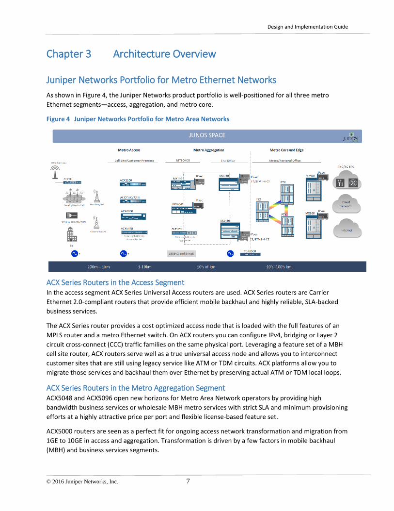
Juniper Networks Portfolio for Metro Ethernet Networks As shown in Figure 4, the Juniper Networks product portfolio is well-positioned for all three metro Ethernet segments—access, aggregation, and metro core.
Figure 4 Juniper Networks Portfolio for Metro Area Networks
ACX Series Routers in the Access Segment In the access segment ACX Series Universal Access routers are used. ACX Series routers are Carrier Ethernet 2.0-compliant routers that provide efficient mobile backhaul and highly reliable, SLA-backed business services.
The ACX Series router provides a cost optimized access node that is loaded with the full features of an MPLS router and a metro Ethernet switch. On ACX routers you can configure IPv4, bridging or Layer 2 circuit cross-connect (CCC) traffic families on the same physical port. Leveraging a feature set of a MBH cell site router, ACX routers serve well as a true universal access node and allows you to interconnect customer sites that are still using legacy service like ATM or TDM circuits. ACX platforms allow you to migrate those services and backhaul them over Ethernet by preserving actual ATM or TDM local loops.
ACX Series Routers in the Metro Aggregation Segment ACX5048 and ACX5096 open new horizons for Metro Area Network operators by providing high bandwidth business services or wholesale MBH metro services with strict SLA and minimum provisioning efforts at a highly attractive price per port and flexible license-based feature set.
ACX5000 routers are seen as a perfect fit for ongoing access network transformation and migration from 1GE to 10GE in access and aggregation. Transformation is driven by a few factors in mobile backhaul (MBH) and business services segments.

Design and Implementation Guide
8 © 2016 Juniper Networks, Inc.
For MBH, transformation is driven by migration to 4G LTE and LTE advanced, LTE small cell and upcoming 5G standards. For business services, transformation is happening because of virtualizing and moving some of the network functions traditionally sitting in the access segment into data centers, which essentially leads to high bandwidth demands in the access and aggregation.
MX Series Routers in the Metro Aggregation and Core Segments MX Series 3D Universal Edge routers are used in the aggregation and core segments and give carriers best in class performance and functional flexibility. Leveraging ability of the head-end Layer 2 service termination it allows collapsing of the MAN edge function with service edge functions in the same routing node. A Metro network based on Juniper platforms would serve equally well providing any connectivity service of any kind—Layer 2 or Layer 3—with service touch point placed at any place of MAN or network cloud.
PTX Series Routers in the Core Segment In geographically separated MANs, early adopters of 100GE may opt for leveraging the PTX Series Packet Transport routers, which provide a core function enhanced by router integrated 100GE optical transponders. These transponders can give the ability to establish a long haul back-to-back connectivity that can span a few hundred kilometers without signal amplification.
Junos Space Platform Enabled by the Junos Space platform, fast remote provisioning reduces operational costs and the demand on your resources, while helping you speed delivery of new services.

Design and Implementation Guide
© 2016 Juniper Networks, Inc. 9
Metro Ethernet as Part of Access and Aggregation Metro Ethernet falls with the access and aggregation domain. As shown in Figure 5 the main use cases in the access and aggregation domain are:
• Mobile backhaul (MBH) • Residential aggregation • Business access • Ethernet exchange • Field area network (FAN)
Figure 5 Universal Access and Aggregation Domain
Metro Ethernet is at the service level of access and aggregation. Specific use cases for Metro Ethernet are:
• Wholesale MBH
• Customer VLAN (C-VLAN) and Service VLAN (S-VLAN) residential delivery model
• Layer 2 and Layer 3 business access
• Direct Internet access
• Multicast delivery
There are several foundational technologies that service levels are based on:
• Carrier Ethernet or Ethernet bridging. Juniper Networks leverages comprehensive carrier grade Ethernet bridging functionality of the ACX and MX series, which represents a dedicated layer within the network architecture.

Design and Implementation Guide
10 © 2016 Juniper Networks, Inc.
• Ethernet OAM. OAM refers to a toolset that can be used for detecting and reporting connection failures, measurement of connection performance parameters or controlling parameters of the service level agreement (SLA). Section Chapter 14 gives and overview and recommendations about OAM deployment within the solution.
• Seamless MPLS with end-to-end restoration techniques and MPLS OAM. This layer includes both MPLS transport and MPLS based services which in turn enable Metro Ethernet services.
• LTE Security. To address 3GPP requirements for 4G LTE Evolved Node B authentication and traffic encryption, Juniper introduced a solution for LTE security gateway. This solution is based on router-integrated security functionality of the MX Series platform and/or SRX series firewall.
• Time and Synchronization. Set of protocols to provide frequency and time synchronization to all nodes across an access and aggregation network. It has less demands for Metro Ethernet use cases and we skip it as design option within current document.
• Network management, software-designed networking (SDN), and service provisioning and control.
The Metro Ethernet use cases are enabled by the same Metro Ethernet services, but differ from one another by a number of things, such as:
• Type of services
• Service topology and Service hierarchy
• Scalability requirements in terms of:
o number of services per network service node
o number of access modes
• Subset of technologies and protocols which comprise the layer of the foundation technologies
While the majority of the Juniper Network Universal Access and Aggregation solutions are based on seamless MPLS as a transport, we do not restrict the Metro Ethernet solution exclusively to MPLS technology. At least in the access and pre-aggregation segments of the MAN, both technologies—Ethernet Bridging and MPLS—are essential parts of the service profiles, are equally feasible, and can be used alone or with each other enabling Metro Ethernet services in full compliance with industry specifications.
Ethernet Bridging as Metro Ethernet Transport There is a set of traditional challenges for the networks that use Ethernet bridging natively as a choice of metro transport:
• Rapid failure detection and service restoration in Ethernet access segment
• Layer 2 loop avoidance
• VLAN tag manipulation

Design and Implementation Guide
© 2016 Juniper Networks, Inc. 11
• Scalability
• Interworking between Ethernet and MPLS segments
All these aspects are covered in the proposed solution. At the same time, we are leaving out of scope discussion of the design aspects of establishing end-to-end MPLS transport in the metro network. Those who are interested in such topic we address this in the Universal Access and Aggregation Mobile Backhaul Design Guide.
In the above diagram (Figure 5) profiles are enabled not by traditional Juniper Networks MPLS services—MPLS pseudowire, L2VPN, VPLS etc.—but instead, we added an abstraction layer which is described in terms of the Metro Ethernet services—E-Line, E-LAN, E-Tree, E-Access.


Design and Implementation Guide
© 2016 Juniper Networks, Inc. 13
Chapter 4 Metro Ethernet Scenarios
Metro Ethernet Scenarios and Service Profiles The service profiles that we discuss in this document can be defined and enabled by Metro Ethernet services with some add-ons. To enable Metro Ethernet services, which cross the access, aggregation, and core segments, this solution proposes the use of different network protocols and services. For example, E-LAN EVC can be enabled by hierarchical VPLS, which represents a combination of a Layer 2 pseudowire signaled with LDP (RFC 4905) in the access network and BGP- or LDP-signaled virtual private LAN service (VPLS) in the aggregation and core segments of the MAN.
There are five use cases for Metro Ethernet that we cover:
• Layer 2 business access (L2BA) • Wholesale mobile backhaul (MBH) • Layer 3 business access and direct Internet access (L3BA and DIA) • Residential aggregation with C-VLAN and S-VLAN multiplay delivery model • Multicast delivery
Layer 2 Business Access Layer 2 Business Access (L2BA) is geared to service providers that offer Ethernet-based Layer 2 circuits to corporate clients and other service providers. This is the most common scenario for carrier Ethernet services. It consists of E-Line, E-LAN, E-Tree, and E-Access within the urban metro area.
Figure 6 Layer 2 Business Access Service Profile
Depending on the transport protocol, MPLS or Ethernet, you can use the MPLS service identifier or the outer VLAN tag (S-VLAN) or both to uniquely identify the EVC and to isolate traffic between different EVCs in the MAN.

Design and Implementation Guide
14 © 2016 Juniper Networks, Inc.
Figure 7 illustrates the case of a MAN that consists of a few segments. Two access segments—Ethernet and MPLS on the left and right hand sides respectively—are interconnected via a metro core/aggregation segment that uses VPLS. The End-to-End EVC provides delivery of the customer traffic, untagged or tagged with C-VLAN, between UNI-A1/A2 and UNI-B. The EVC is defined at its ends with attributes that are summarized in the first and sixth column of the table in Figure 8.
Enabling Metro EVC in Junos, gives details about mapping EVC attributes to Junos features.
Figure 7 Layer 2 Business Access Reference Architecture
VPLS is used to provide stitching between access segments based on a different set of protocols, and is recommended in the core and aggregation segments of medium and large metro Ethernet networks. It works equally well as a VPLS hub aggregating MPLS layer 2 circuits or physical Ethernet links. Figure 8 displays details about the network services that are used to enable EVC. Junos has multiple features to make this type of stitching as reliable as possible, and to provide interoperability for different flavors of the spanning tree protocol or Ethernet Ring Protection (ERP), G.8032v1/v2, when stitching Ethernet segments. The only exception is the E-Line service, which can be enabled by an MPLS layer 2 circuit (pseudowire) between two physical or logical ports or MPLS access nodes.
Figure 8 Metro EVC Deployment with Dual-homed Access Segments

Design and Implementation Guide
© 2016 Juniper Networks, Inc. 15
VPLS can be deployed in the access segment, but it is not a common scenario. For historical reasons or because of a multivendor network environment, the MAN provider can have different flavors of VPLS deployed in the access and aggregation segments. For example, BGP, LDP, or FEC129. The MX series router provides interoperability or stitching between the VPLS segments. For details of using VPLS in Junos platforms to enable Metro Ethernet services see Specifics of VPLS Deployments in the MAN
In scenarios with large, flat Ethernet switching, the MAN provider sooner or later will be challenged by the lack of VLAN tags required to enumerate and split traffic of different EVCs. Again, VPLS in the middle solves this problem and enables the flexibility of using overlapped VLAN spaces for different access segments (see S-VLAN Translation of the EVC between Ethernet Rings). This is another reason to think about VPLS as deployment option in the metro Ethernet network.
In most cases there is a pair of aggregation nodes, marked as AGN1.1 and AGN1.2, in Figure 8 deployed for each segment. In this solution, we propose techniques that provide dual-homed and multi-homed connectivity between a pair of VPLS hubs and access segments of both Ethernet and MPLS, while addressing challenges such as network resiliency and layer 2 loop avoidance (see Providing Resiliency in Metro Ethernet Networks).
There are more scenarios where both segments use Ethernet switching or MPLS or where one of the access nodes is connected to a third party MAN. Deployment Scenarios and Recommendations gives recommendations for multiple combinations, including simplistic cases of enabling E-Line service with an end-to-end pseudowire between two MPLS access nodes, and a choice of platforms for roles in the MAN.
Wholesale Mobile Backhaul The wholesale MBH scenario is geared to MAN operators that provide leased line services to a mobile operator, which in turn uses them to backhaul and aggregate traffic from numerous base stations to the central location close to the mobile controller.
The mobile operator can use the same architecture for its transmission department to its mobile department, providing an explicit demarcation point between two administrative domains. In general, the mobile provider leases connectivity services over a third party service provider Layer 2 Metro Ethernet network or over Layer 3 private or even public networks, which can be part of the macro or small cell deployments. In this document we are focused only on Layer 2 cases.
The drivers for the wholesale model are: regulations, business models, cost of ownership, lack of expertise in the operation of large access and aggregation wireline networks, and lack of infrastructure in the region. The percentage of Metro Ethernet services provided for mobile backhaul is significant and is growing.

Design and Implementation Guide
16 © 2016 Juniper Networks, Inc.
Figure 9 Wholesale MBH Use Case
In Figure 9 Metro Ethernet services, E-LAN, E-Line and E-Tree, are provided between the mobile operator cell site routers (CSR) or cell site switch (CSS) and provider edge (PE) routers located at a national or regional POP. With respect to metro services, the CSR and PE are seen as customer CPEs. UNI represents a demarcation between the MAN and the mobile operator.
Leased Ethernet lines provided to the MBH network provide a similar service and has similar functions as they do for Layer 2 Business Access (L2BA). Things that are different are scale, topologies, and additional functions needed for the MBH network—namely synchronization and IPsec.
The problem statement of MBH can be summarized as connecting 1000s of hosts to a central location in secure and reliable way. A challenging factor is the scale of the centrally located metro edge platform that connects the mobile core network to multiple cell sites. In real deployments it easily leads to thousands of Ethernet connections, each with a dedicated OAM session that needs to be established. The same challenges can be seen on the PE routers of the mobile operator’s EPC. These routers aggregate Ethernet connections toward cell sites, and should run end-to-end Ethernet Connectivity Fault Management (CFM) to track EVC status.
In the last few years, mobile operators have actively migrated their 2G/3G and High Speed Packet Access (HSPA) radio base stations from legacy TDM/ATM transport to Ethernet. E-Line has become the most demanding service to provide connectivity between the base transceiver station (BTS)/NodeB to the Base Station Controller (BSC)/Radio Network Controller (RNC) in metro areas. LTE networks were
Design and Implementation Guide
© 2016 Juniper Networks, Inc. 17
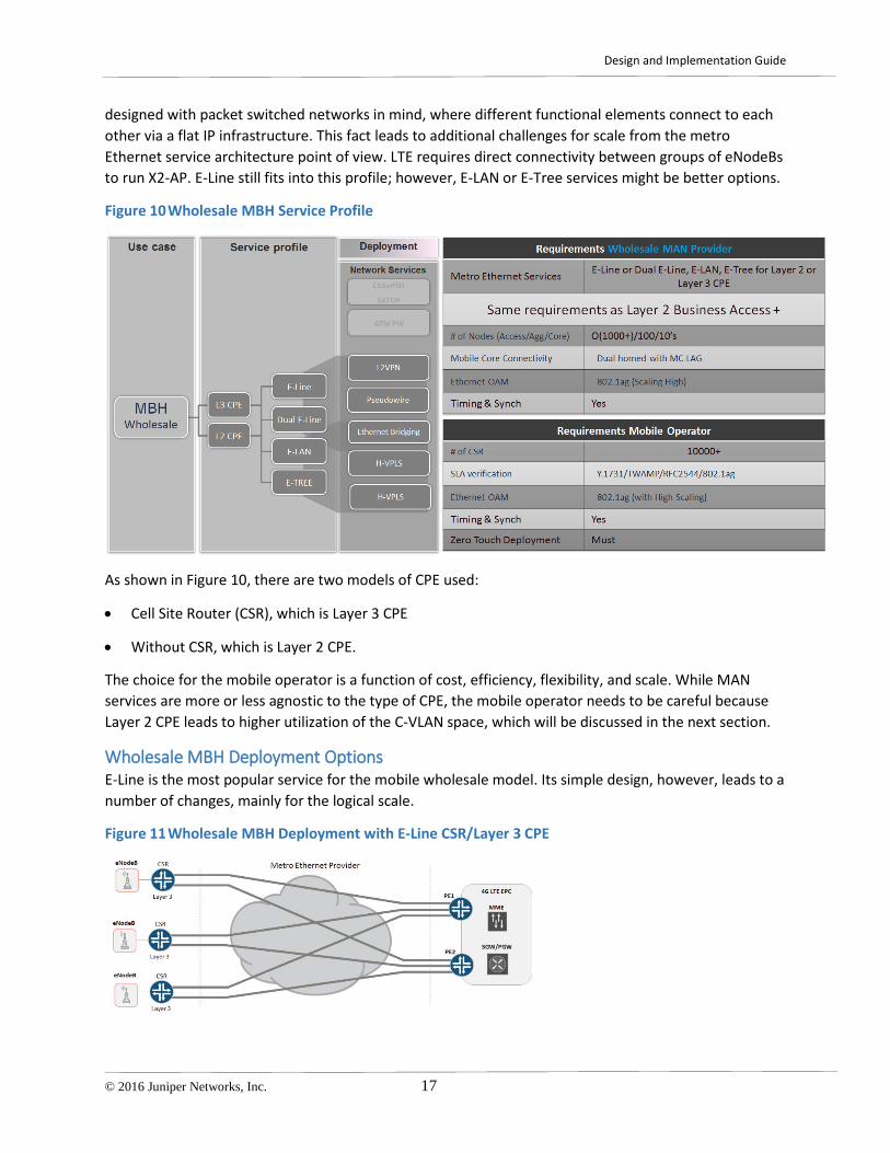
designed with packet switched networks in mind, where different functional elements connect to each other via a flat IP infrastructure. This fact leads to additional challenges for scale from the metro Ethernet service architecture point of view. LTE requires direct connectivity between groups of eNodeBs to run X2-AP. E-Line still fits into this profile; however, E-LAN or E-Tree services might be better options.
Figure 10 Wholesale MBH Service Profile
As shown in Figure 10, there are two models of CPE used:
• Cell Site Router (CSR), which is Layer 3 CPE
• Without CSR, which is Layer 2 CPE.
The choice for the mobile operator is a function of cost, efficiency, flexibility, and scale. While MAN services are more or less agnostic to the type of CPE, the mobile operator needs to be careful because Layer 2 CPE leads to higher utilization of the C-VLAN space, which will be discussed in the next section.
Wholesale MBH Deployment Options E-Line is the most popular service for the mobile wholesale model. Its simple design, however, leads to a number of changes, mainly for the logical scale.
Figure 11 Wholesale MBH Deployment with E-Line CSR/Layer 3 CPE

Design and Implementation Guide
18 © 2016 Juniper Networks, Inc.
The following figures illustrate deployment scenarios where a pair of mobile operator’s routers PE1 and PE2 are connected to the EPC on the right hand side and to the Metro Ethernet network on the left. E-Line EVC’s are provided by third party MAN operators to interconnect multiple Layer 3 CSRs or Layer 2 non-CSRs to the PE1 and PE2 nodes.
The following sections cover three wholesale MBH deployment options:
• Wholesale MBH Deployment with Dual E-Line Services and Layer 3 CPE or CSR
• Wholesale MBH Deployment with Dual E-Line Services and Layer 2 CPE or Cell Site Switch (CSS)
• Wholesale MBH Deployment with E-LAN/E-Tree Services
Wholesale MBH Deployment with Dual E-Line Services and Layer 3 CPE In Figure 12, each CSR is connected by two EVCs to PE1 and PE2 (MX series routers). They use a pair of physical interfaces, UNI-A1.1 and UNI-A1.2. The CSR’s are connected to metro access nodes (ACX series routers) via untagged Ethernet II links or 802.1q with VLAN tags. Meanwhile the UNI, which connects EPC-PE router, always needs to be assigned with a C-VLAN tag per cell site, which allows the PE to correctly demultiplex traffic belonging to different connections or CSRs.
Figure 12 Wholesale MBH Deployment with Dual E-Line Services and Layer 3 CPE
If a mobile operator requires an untagged link at the UNI connected to the CSR, the metro access node should be configured to push a unique C-VLAN to ingress frames and pop it at egress before sending a frame to the CSR. To do so, use the vlan-map or native vlan configuration statement at the UNI of the metro access node. On the PE, a VLAN has significance only within a physical port, thus C-VLAN uniqueness needs to be provided only for CSRs with EVCs that are terminated on the same port of the metro PE router.

Design and Implementation Guide
© 2016 Juniper Networks, Inc. 19
Depending on the type of protocol used to enable the EVC, Ethernet bridging, or MPLS, the access node may be required to perform a second VLAN tag push operation to add an S-VLAN tag to uniquely identify the EVC within the MAN. In our example for distinctness we choose MPLS. EVP-LINE EVC is enabled by the MPLS pseudowire signaled by targeted Label Distribution Protocol (tLDP) and adding the S-VLAN is considered optional.
To map backhaul traffic to the right forwarding class, the access node should use a DSCP classifier. An interface-specific firewall filter and policer enables the required bandwidth profile attributes of the EVC. To prevent L2CP traffic tunneling, corresponding MAC filters should be configured at the access port.
At the opposite side, the UNI is configured with per-EVC bandwidth profiles that bundle a single C-VLAN per EVC and multiplex multiple EVCs on the single physical UNI.
To track the status of the EVC and provide traffic switchover between EVCs, you must use an OAM mechanism, which can be either CFM or BFD. The number of OAM sessions on PE routers can easily go far beyond few thousands, which is also a function of the keepalive periods used for CFM and BFD. The longer the continuity check interval, the longer switchover time between EVCs. This problem can be solved when you configure access nodes, such as ACX series routers, with CFM to track the connectivity status of the EVC between UNI-A on the left and UNI-B on the right. Under special conditions, the MAN can leverage the control plane of the pseudowire and signal back a critical network failure to the CSR if the virtual-circuit goes down. We will illustrate those cases in the next chapter.
To provide effective and scalable OAM functioning on an MX platform, choose hardware that supports processing of CFM/BFD in the line card rather than in the Routing Engine. We also recommend that you add configuration for policing CFM traffic to avoid DDOS failures at the Metro PE.
Wholesale MBH Deployment with Dual E-Line Services and Layer 2 CPE A dual E-Line EVC model can be used for CSR-less Layer 2, deployment scenarios. Differences in the deployment are summarized in the table of Figure 13. The first difference is the type of OAM used between cell site switch and the EPC-PE, which in this case is limited by the CFM protocol. The second difference is a higher number of C-VLANs per EVC.
When backhauling LTE traffic, a dedicated C-VLAN should be reserved and backhauled per cell site switch and per mobile application, which at worst case leads to five C-VLAN tags per cell tower: S1-U, S1-MME, X2-U, X2-C, and Management. A single physical port cannot operate more than 4094 VLANs, so this factor should be considered when planning this model.

Design and Implementation Guide
20 © 2016 Juniper Networks, Inc.
Figure 13 Wholesale MBH Deployment with Dual E-Line Services and Layer 2 CPE
The dual E-line model has the simplest network architecture. However, its design is not an easy one because the PE needs to be able to provide high logical scale and a reliable solution because several thousand cell towers depend on it. Some mobile operators may have concerns about a non-optimal forwarding path for the X2 traffic, as well as additional delay generated by the longer distances, which becomes more critical in LTE advanced type mobile networks.
Wholesale MBH Deployment with E-LAN/E-Tree Services As an alternative to E-Line you can consider Wholesale MBH services based on E-Tree and E-LAN services. In this example, a 4G EPC-PE router is interconnected with multiple cell sites via a single EVC of E-Tree type for S1 traffic and E-LAN for X2.
Figure 14 illustrates a deployment without CSRs where a set of C-VLANs are configured at both ends of the EVC. There is one C-VLAN per mobile application, and C-VLANs are shared across all leaves of the EVP-Tree EVC. Traffic between leaves is restricted by definition of the E-Tree. At the metro PE, E-Tree service is enabled by VPLS/VSI routing instances. At the access node, EVC is enabled by MPLS pseudowires terminated directly into the metro PE or on to the aggregation VPLS hub within the MAN.
To add resiliency, the EPC-PE is connected to Metro PE by a multi-chassis LAG with active-active or active-standby mode.
There is another E-LAN EVC that provides direct connectivity between cell sites and enables X2 communication.

Design and Implementation Guide
© 2016 Juniper Networks, Inc. 21
Figure 14 Wholesale MBH Deployment with E-LAN/E-Tree Services
This design eliminates some limitations of the dual E-Line model:
• Optimal forwarding path for X2.
• Low provisioning costs for adding new nodes. No provisioning is required at EPC-PE when adding a new leaf SCR of the EVC. The C-VLAN model is simple.
• Traffic switchover between two metro PEs is managed by the MAN operator and leverages VPLS (IGP/LDP/BGP) control plane and MAC-flash signaling.
• Although one EVC will lead to multiple point-to-multipoint OAM sessions, a continuity check interval can be chosen rather bland due to restoration are not locked to CFM anymore and overall E-OAM is not a limiting factor in this type of design.
On the flip side:
• The design of the MPLS services is more complex.
• MAC learning becomes part of the service.
• Additional precautions are required to avoid Layer 2 broadcast, unknown unicast, and multicast (BUM) traffic storms.

Design and Implementation Guide
22 © 2016 Juniper Networks, Inc.
Layer 3 Business Access and DIA Service Profile The Layer 3 Business Access service profile is geared to service providers that offer IP services. Layer 3 VPN is the most widely deployed MPLS application.
The main goal of an IP-VPN service is to offer private IP connectivity service between different locations of an enterprise. Given the wide geographical distribution and capacity needs of the branch offices and main office, the IP-VPN services are provided over a wide range of connectivity types and offer a range of connectivity speeds with very stringent SLAs and availability targets.
Figure 15 Layer 3 Business Access and Direct Internet Access Service Profiles
In a private network where traffic streams from two customers does not mix, the service providers implement an IP/MPLS network with MP-BGP signaling where a common IP/MPLS network offers VPN services to end customers.
In addition to the IP connectivity services, carriers offer many value added services, such as stateful firewalls, NAT to hosted voice, and cloud connectivity to their corporate customers.
Usually there are dedicated L3 PE service routers in the service provider network that are configured with interfaces to interconnect with the business customer’s CPE device. These interfaces serve as a policy enforcement point of the Layer 3 service. There two ways customer traffic can be delivered to the Layer 3 service point:
• The customer’s CPE device can have a direct physical link to the service PE.
• Traffic can be backhauled over Metro EVC from the access node to the service PE where the actual Layer 3 service is provided. This Layer 2 circuit is known to be a subset of the L3BA service profile (see Figure 15).

Design and Implementation Guide
© 2016 Juniper Networks, Inc. 23
Figure 16 Layer 3 Business Access with Centralized Service Edge
In most cases a Layer 2 circuit originates in the access network and is terminated at the ENNI interface of the Metro Network PE router, which in turn has a direct link to the service PE router. This is called a VLAN hand-off (see Figure 16). ENNI sets an explicit demarcation between Layer 2 EVC in the metro edge and the Layer 3 service attachment point in the service PE router. Strictly speaking interfaces between the Layer 3 PE and the Metro edge network do not exactly fit the MEF definition for ENNI. However, we still prefer to keep this notation. It reflects the fact that in most cases the physical interface between the metro edge and PE router carries both VLAN tags—the outer VLAN tag or S-VLAN identifies either the UNI or access node, the inner tag or C-VLAN identifies customer VLAN tag if any. Both tags together allow the Layer 3 PE router to demultiplex traffic from different customers. Deployment scenarios for the simple VLAN hand-off case are covered by:
• Layer 2 Business Access for Layer 2EVC
• Business Edge Solution Design and Implementation Guide for Layer 3 VPN
Another option is when a Layer 2 circuit from the access network is terminated directly into a L3VPN at the service PE router. This scenario is enabled by an MPLS pseudowire and L2VPN services, and is known as Pseudowire Head End Termination (PWHT) to the Layer 3 VPN at the service edge router. This technique eliminates the provisioning point with VLAN hand-off between the metro edge and PE router. Now, the Layer 2 segment can be seamlessly stitched with service edge by means of a regular interface between two label switching routers (LSR).
It also enables flexibility to where in the MAN a Layer 3 service point can be placed. In some cases, the access or aggregation segment of the MAN may acquire the edge service function so that the Layer 3 service enforcement point is seamlessly moved from provider business edge PE into the AGN router in the MAN.

Design and Implementation Guide
24 © 2016 Juniper Networks, Inc.
Figure 17 Layer 3 Business Access with Service Edge Distributed into Aggregation Segment
There are two service sets that relate to the distributed Layer 3 edge scenario:
• L3VPN with PW in access and Hierarchical L3VPN (see Figure 18).
• Hierarchical L3VPN pushes the service point to the access node (ACX series router) while H-PE function—RFC7024—of the AGN routers (MX series routers) enables scale. With this technique the provider can build an extremely large network that includes of hundreds of thousands of access nodes. This type of deployment is recommended as the primary method for the LTE MBH owned by mobile operators. For deployment details, see Universal Access and Aggregation Mobile Backhaul Design and Implementation Guide.

Design and Implementation Guide
© 2016 Juniper Networks, Inc. 25
Figure 18 Layer 3 Business Access with Service Edge Distributed into Access Segment
The direct Internet access (DIA) profile is geared to service providers that offer Internet connectivity to their corporate customers. Given the wide geographical distribution and capacity needs of branch offices and the main office, the Internet connectivity services are provided over a wide range of connectivity types and access networks, and offer a range of connectivity speeds with very stringent SLAs and availability targets.
The current solution supports a centralized or distributed model for the DIA service when the MAN provides a Layer 2 circuit between customer CPE and a dedicated provider INET-PE. The same design consideration as for L3BA access are applicable when backhauling DIA traffic. L3BA and DIA often come as a service bundle. However, different services may require delivery to different PE nodes, thus different EVCs should be provided for backhauling L3BA and DIA services.
Metro EVCs of any type—E-Line, E-LAN or E-Tree—that are used to backhaul traffic for L3BA or DIA can be enabled in the network with same set of protocols as we described for Layer 2 Metro Ethernet. However, having them terminated directly into Layer 3 service PE leads to new set of challenges that should be examined carefully.
Residential Aggregation Use Case In the residential aggregation use case, operators provide broadband service to residential customers. The metro Ethernet network aggregates Ethernet links from broadband access nodes, such as DSLAMs OLTs or CMTSs, and delivers traffic to the Broadband Network Gateway (BNG), which provides actual broadband edge (BBE) services to the subscriber. The BNG can be located at the service provider edge or distributed to the metro area network itself. The distinctive part of the residential use case is that besides Internet connectivity, service providers deliver services, such as voice and video to the home network. That is the essence of the triple play service model of Data, Voice, and Video services provided
Design and Implementation Guide
26 © 2016 Juniper Networks, Inc.
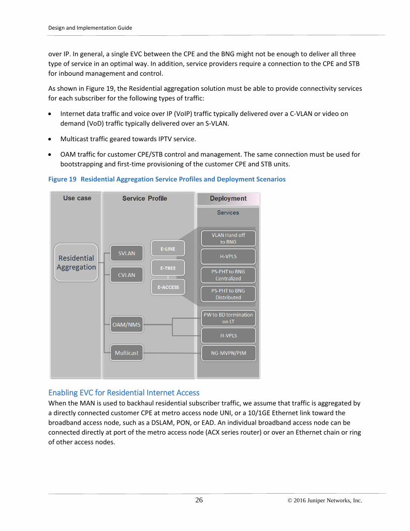
over IP. In general, a single EVC between the CPE and the BNG might not be enough to deliver all three type of service in an optimal way. In addition, service providers require a connection to the CPE and STB for inbound management and control.
As shown in Figure 19, the Residential aggregation solution must be able to provide connectivity services for each subscriber for the following types of traffic:
• Internet data traffic and voice over IP (VoIP) traffic typically delivered over a C-VLAN or video on demand (VoD) traffic typically delivered over an S-VLAN.
• Multicast traffic geared towards IPTV service.
• OAM traffic for customer CPE/STB control and management. The same connection must be used for bootstrapping and first-time provisioning of the customer CPE and STB units.
Figure 19 Residential Aggregation Service Profiles and Deployment Scenarios
Enabling EVC for Residential Internet Access When the MAN is used to backhaul residential subscriber traffic, we assume that traffic is aggregated by a directly connected customer CPE at metro access node UNI, or a 10/1GE Ethernet link toward the broadband access node, such as a DSLAM, PON, or EAD. An individual broadband access node can be connected directly at port of the metro access node (ACX series router) or over an Ethernet chain or ring of other access nodes.

Design and Implementation Guide
© 2016 Juniper Networks, Inc. 27
There are different access and service delivery models in the broadband network. At high level, those models include:
• Protocols that are used to establish Layer 2 connectivity between the customer CPE and the BNG, such as PPPoE, IPoE, or L2TP.
• VLAN models used to split traffic between customers and services—C-VLAN or S-VLAN model
• Support of IPv4 and IPv6 traffic.
• Protocols that are used to set up network connectivity, and authenticate and authorize subscriber in the network, such as PPP, DHCP, or RADIUS.
Figure 20 Network Architecture for E-Tree EVC between Residential Customer CPE and BNG
While configurations of the residential CPE and the BNG for service models is different, the metro Ethernet network is agnostic to these differences. Connectivity is provided by the regular EVC—either multiple E-Lines or E-Tree—between UNI/ENNI of the access node and ENNI of Metro PE interconnected with BNG. This delivery model has been discussed in Layer 3 Business Access and DIA Service Profile. To enable E-Line or E-Tree EVC follow the recommendations in Deployment Scenarios and Recommendations.
Figure 20 illustrates a high level architecture where the E-Tree EVC is enabled by the pseudowire that originated from the metro access node and is terminated into a dedicated VPLS routing instance at the aggregation nodes (MX series routers) of the MAN. A single VPLS instance can be used to aggregate all attachment circuits from multiple access nodes for the residential service profile. MPLS pseudowires can be originated either per UNI of the metro AN or per individual AN. See MPLS AN with Multiple UNIs per Customer for details about how to terminate multiple pseudowires from the same access node into a single VPLS instance on MX series router. Traffic via VPLS is delivered to and from the metro edge PE router and towards the BNG. In this scenario, the UNI/ENNI interface between the metro Edge and the

Design and Implementation Guide
28 © 2016 Juniper Networks, Inc.
BNG uses a VLAN hand-off model—described in Layer 3 Business Access and DIA Service Profile. Depending on service delivery model, S-VLAN or C-VLAN, you may need to deploy variations of CVLAN bundling and EVC multiplexing. See the notes after Figure 7.
Another scenario for residential aggregation is driven by the E-Line services that are enabled with MPLS pseudowire and pseudowire head end termination (PWHT) at the BNG. This scenario is illustrated in Figure 21. MPLS pseudowire emulates an Ethernet circuit originated from the Metro access node or from the broadband access node and terminated directly at BNG—see PW2 and PW3 in the diagram.
Figure 21 Network Architecture for E-Line EVC with Head End Termination at BNG
In the above example an individual pseudowire can be originated per single UNI or per metro access node. If the number of the attachment circuits at the centrally located BNG is too high, in the 1000s, then you may consider an option where multiple pseudowires are first aggregated and stitched into a single pseudowire at the aggregation metro node. Stitching is provided through a locally configured virtual switch instance (VSI).
If subscriber management is enabled on the MX series routers, then pseudowire termination—LDP L2 circuit or L2VPN—is accomplished using a pseudowire services (PS) interface.
Such a design requires MPLS transport protocols to be enabled end-to-end from the broadband access to the provider service edge. It is highly probable that the MAN and network service edge segments belongs to different autonomous systems (ASs) and different administrative domains even within the same service provider. In such a case, MPLS transport infrastructure spans multiple ASs and uses stitching techniques to establish a monolithic MPLS transport infrastructure between network regions. This technique is described by the seamless MPLS network architecture, IETF’s draft-ietf-mpls-seamless-mpls-7, which is fully supported by the solution. As previously stated, seamless MPLS is an essential aspect of the design and fits to multiple metro Ethernet use cases. For details about how to
Design and Implementation Guide
© 2016 Juniper Networks, Inc. 29
enable seamless MPLS in the access and aggregation network refer to the Universal Access and Aggregation Mobile Backhaul Design and Implementation Guide.
Enabling Multicast Delivery in the MAN There are several applications that drive the deployment of multicast service in the MAN. Backhauling of IPTV/OTT services is a common application within the triple play offerings for residential consumers.
Here we recommend how to provide multicast traffic distribution in the MEN for the residential use case. Options are depicted in Figure 22, and can be classified by type of the network protocols used to enable Multicast traffic delivery and type of connectivity between the access node and a residential subscriber.
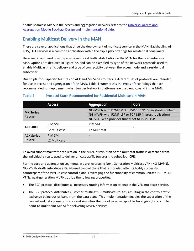
Due to platform-specific features on ACX and MX Series routers, a different set of protocols are intended for use in access and aggregation of the MAN. Table 4 summarizes the types of technology that are recommended for deployment when Juniper Networks platforms are used end-to-end in the MAN.
Table 4 Protocol Stack Recommended for Residential Multicast in MAN
Access Aggregation Core
MX Series Router -
NG-MVPN with P2MP MPLS LSP or P2P LSP in global context NG-MVPN with P2MP LSP or P2P LSP (ingress replication) NG-VPLS with provider tunnel set to P2MP LSP
ACX5000 PIM SM PIM SM
- L2 Multicast L2 Multicast
ACX Series Router
PIM SM - -
L2 Multicast
To avoid suboptimal traffic replication in the MAN, distribution of the multicast traffic is detached from the individual circuits used to deliver unicast traffic towards the subscriber CPE.
For the core and aggregation segments, we are leveraging Next-Generation Multicast VPN (NG-MVPN). NG-MVPN drafts introduce a BGP-based control plane that is modeled after its highly successful counterpart of the VPN unicast control plane. Leveraging the functionality of common unicast BGP-MPLS VPNs, next-generation MVPNs utilize the following properties:
• The BGP protocol distributes all necessary routing information to enable the VPN multicast service.
• The BGP protocol distributes customer-multicast (C-multicast) routes, resulting in the control traffic exchange being out-of-band from the data plane. This implementation enables the separation of the control and data plane protocols and simplifies the use of new transport technologies (for example, point-to-multipoint MPLS) for delivering MVPN services.

Design and Implementation Guide
30 © 2016 Juniper Networks, Inc.
Figure 22 Multicast Delivery for the Residential Use Case
The use of a BGP-based NG-MVPN control plane enables the support of both flexible topologies (for example, extranet or hub-and-spoke) and IPv6 addressing. Implementing IPv6-based NG-MVPN enables the use of MPLS encapsulation for IPv6 multicast. As an added benefit, IPv6-based next-generation MVPN uses the same model as IPv6 VPN for unicast (as defined in RFC 4659), ensuring a more compatible integration of IPv6 multicast services with existing IPv4 next-generation MVPN or IPv6 unicast VPN models.
BGP MVPN provides multihoming support for connecting a multicast source to two provider edge (PE) devices, enabling subsecond failover from a PE node failure. The autodiscovery of available MVPN members with BGP provides a high degree of automation for establishing provider tunnels that are used to carry MVPN data between PE devices.
It is highly probable that another PE router resides between the source and the upstream Metro PE router. In this case, to enable discovery of the source by Metro PEs, they are configured as Rendezvous Points (RPs) for the PIM instance that hosts the source of multicast streams. For redundancy, you can configure several RPs, each on a different Metro PE. Rendezvous points can share the same IP address

Design and Implementation Guide
© 2016 Juniper Networks, Inc. 31
(Anycast RP). Information about active sources that are registered on different RPs is exchanged automatically using BGP, eliminating the need to run MSDP between RPs.
In this scenario, BGP is used to signal information about active multicast sources and receivers and to facilitate PE router auto-discovery. Figure 23 shows how multicast traffic is delivered over an MPLS core using a provider tunnel, P2MP, signaled using RSVP-TE.
Figure 23 Network Architecture for Multicast Traffic Delivery in MEN
In the access segment of the MAN, the PIM protocol is proposed as main method for multicast traffic delivery from the aggregation node towards the metro access node. This method is combined with NG-MVPN in the core end aggregation segments (see Figure 23). Customer STBs signal group membership to metro AN routers using IGMP and are delivered within customer a Video VLAN. Metro access nodes use PIM-SM to distribute join/prune messages towards metro aggregation nodes that are configured as Anycast Rendezvous Points (RP) in the access PIM domain. Routing information from the PIM domain is distributed into MVPN towards upstream Metro PE via MB-BGP.
In this solution, distribution of the multicast routing information in the aggregation and core segments is tied to the global VRF context. This is achieved by configuring a Virtual Routing and Forwarding (VRF) routing instance of the mpls-internet-multicast instance type. This VRF is used only for control plane procedures. It does not support interface configurations. All multicast and unicast routes used for IP multicast are associated only with the default routing instance (inet.0).
Provider tunnels are enabled by the P2MP LSP template that is associated with the forwarding plane for the multicast traffic by adding corresponding configuration under the mpls-internet-multicast VRF at the upstream Metro PE router.
Head End Metro PE Metro AGN routing-instances { Internet-Multicast { instance-type mpls-internet-multicast; provider-tunnel {
routing-instances { Internet-Multicast { instance-type mpls-internet-multicast; protocols {

Design and Implementation Guide
32 © 2016 Juniper Networks, Inc.
rsvp-te { label-switched-path-template { NGMVPN; } } } protocols { mvpn; } }
mvpn; } } }
Options for how individual subscribers can be connected to the network are:
• Direct connectivity at the ACX access router
• Connectivity provided by third-party access nodes, such as a DSLAM, PON, or EAD.
The type of connectivity has an implication to the technique that is used to place the multicast stream of the group into subscriber Video VLAN.
If the customer CPE is directly connected at UNI of the metro access node (Metro-AN), then Metro-AN is responsible for insertion of the multicast streams to the customer video VLAN based on IGMP joins received from the customer IPTV STB—see Figure 23.
This is achieved by the following configuration options at the Metro AN (ACX series router):
• Each logical interface unit (IFL) of the subscriber UNI with assigned customer video VLAN are placed into the bridge domain (BD)
• IGMP snooping is enabled at IFLs of the BD
• IGMP protocol is enabled on IRB
• No-local-switching is enabled on CPE facing IFLs of the BD
• IRB interface added to PIM domain
If Metro-AN is connected to the broadband access node (BB-AN), then the BB-AN should be responsible for multicast stream delivery to the customer video VLAN. Other options will lead to suboptimal multicast traffic replication on the link between the BB-AN and the Metro-AN. In this scenario, instead of an IRB interface the Metro-AN should be configured with a dedicated logical IFL on the physical port connected to the BB-AN:
• Assign a dedicated Multicast VLAN tag to the IFL
• Configure IFL with IGMP
• Add IFL to the PIM domain
When the service provider uses Ethernet bridging as a transport for the Ethernet services in the access segment, multicast traffic delivery is achieved by placing it into dedicated Multicast VLAN. This method can be combined with NG-VPLS to distribute multicast traffic in the aggregation and core of the MAN.

Design and Implementation Guide
© 2016 Juniper Networks, Inc. 33
Enabling Connectivity for the Inbound OAM of the CPE/STB To provide an inbound management, control, and zero touch provisioning (ZTP) of the IPTV STB devices, a dedicated connectivity service should be enabled over the MAN. This connectivity service may also be used to bootstrap and auto provision the customer CPE when it is first connected to the network.
A network operations center resides in the provider network and uses either a global context or a dedicated Layer 3VPN to establish inbound connectivity to the access nodes of the MAN. For security, we recommend that you establish a dedicated L3VPN to manage customer onsite devices.
A required connection service is established by the E-Tree Ethernet virtual connection from Metro-AN towards Metro-AGN where E-Tree service can be stitched with management L3VPN via IRB interfaces. Figure 24 shows the service architecture for MPLS access segment.
Figure 24 High Level Architecture for Providing MNG Control and ZTP for STB
Configuration of the Metro-AN for multicast traffic delivery has already enabled bridge domains that aggregates logical interfaces (IFL) with a customer VLAN assigned to each IFL. Within this solution we are leveraging a VPLS light configuration option of the ACX series router that can be enabled with the following configuration options:
1. Logical tunnel (LT) interface between the vlan-bridge and the vlan-ccc familys peers
2. Add a vlan-bridge peer unit of the LT interface into the BD for the Video VLAN
3. Originate a single or active/standby MPLS pseudowire towards the Metro-AGN, and terminate it in the VPLS routing instance. A single VPLS instance at the VPLS hub can be shared for connection to multiple Metro-ANs.
The last step is to provide connectivity to the L3VPN:
4. Enable traffic forwarding between the VPLS routing instance and the management L3VPN by adding an IRB interface to the configuration of the VPLS and L3VPN at the Metro-AGN

Design and Implementation Guide
34 © 2016 Juniper Networks, Inc.
At this point connectivity between Management and control system of the IPTV STB can be established.
To enable bootstrapping of the customer CPE you can enable Native VLAN at the access port of the Metro-AN so that any untagged traffic, such as an initial BOOTP or DHCP request, will be forwarded within the native VLAN towards management L3VPN. DHCP relay activated at IRB interface of the Metro AGN router allows the assigning of an initial network configuration to the STB/CPE and enables further provisioning of the customer unit with production configuration.
The same service architecture can be used when Ethernet is chosen as a transport protocol for the metro Ethernet services in the access segment of the MAN. See Deployment Scenarios and Recommendations for details about configuring E-Tree EVC with Ethernet as the native transport in the access segment.

Design and Implementation Guide
© 2016 Juniper Networks, Inc. 35
Chapter 5 Enabling Metro Ethernet Services on Junos Platforms
Design Considerations, Definitions, and Prerequisites The solution for Metro Ethernet services defines use cases through the eight types of metro Ethernet EVCs that are established in operator networks end to end—between UNIs and ENNIs. In MEF notations the EVC is defined at an abstract level, and is seen as a monolithic Ethernet virtual connection—point-to-point or multipoint-to-multipoint, which has the same identifier (EVC ID) at both ends. EVCs are defined in port and VLAN-based flavors. Ethernet OAM protocols, such as CFM, are used as unified control plane protocols to track the status of the end-to-end connection. The Ethernet OAM protocol enables the connection-oriented properties of metro Ethernet services over inherently connectionless Ethernet environment.
EVC is a conceptual notion and may not directly correspond to vendor-specific implementations. In reality, due to leveraging a different set of protocols in different network areas, EVC may have some structure or hierarchy. To distinguish EVC you will use identifier(s) that are specific to the protocols that enable EVC in a given segment. In the following section, we will show how EVC definitions and attributes given by MEF, and notations given by JUNOS correspond. Some attributes have a close meaning. Others, such as coupling flags or the three label COS model, are not obvious and require further explanation.
The MAN design does not end at this point. There are other considerations that are not defined by the MEF, but which are still integral parts of the design (See Table 9).
For the network transport layer, we consider MPLS a choice for the pre-aggregation, aggregation, and core segments. In the access segment, you can choose between two types of technology:
• Seamless MPLS
• IEEE 802.3, IEEE 802.1q, IEEE 802.1ad Ethernet environment; sometime referenced in this document as native Ethernet
Enabling MPLS in the MAN leads to a number of design options. Once the MPLS network infrastructure is deployed, you can activate any MPLS-based service at any point in the network.

Design and Implementation Guide
36 © 2016 Juniper Networks, Inc.
Figure 25 Decoupling Network Layers
Figure 25 illustrates the concept of the decoupling and independence of the network layers in a seamless MPLS network architecture. This concept leads to a fundamental benefit that you can get by pushing MPLS into the access network. Here and below we assume that the MPLS transport is already in place and is considered as a prerequisite for establishing MPLS-based Layer 2 services on top of it.
Prerequisites are:
• Setting up a physical topology
• Establishing IP routing (ISIS, OSPF, BGP)
• Establishing and intradomain MPLS LSPs
• Establishing interdomain hierarchical LSP signaled with BGP-LU and LDP-DOD, if applicable
• Setting up functions of network resiliency and fast restoration at MPLS transport Layer
In the case of Ethernet bridging in the access segment, no special prerequisites are required until mentioned in this document.
For details about enabling the seamless MPLS transport Layer, see the Universal Access and Aggregation Mobile Backhaul Design and Implementation Guide.
Deployment Topologies Real deployment scenarios for the access and aggregation network may significantly vary in terms of number of segments and number of nodes per segment. To give a sense of how large a network could be, we are using two network models:
• Medium scale shown in Figure 26
• Large scale shown in Figure 27
Each network is a Universal Access and Aggregation (UA&A) network that provides services for all three types of consumers—MBH, business access, and residential access and aggregation simultaneously. Traffic is backhauled from the consumer to the corresponding service edge router.

Design and Implementation Guide
© 2016 Juniper Networks, Inc. 37
Depending on the actual use case, the service edge function can be moved closer to the access. Those use cases are covered in later chapters.
To derive scaling requirements for each type of node in the network, you can make assumptions about access nodes port utilization per each type of consumer. To get to the final result you can take into account the services inventory provided in Table 22. We did this calculation as part of the solution development process.
The medium-sized UA&A network has 2560 network nodes in one metro area. A larger national network with 10 different metro areas needs about 25,000 routing nodes.
Figure 26 Medium scale Universal Access and Aggregation Network
Table 5 gives an indication of size of the medium-sized solution.
Table 5 List of Nodes for Metro Area Network of Medium Scale
Network Segment AG3 Nodes
AG2 Nodes
AG1 Nodes Access Nodes Total
Regional network 2 16 256 2560 2834 AG3 - 16 256 2560 2832 AG2 ring - 2 32 320 352 AG1 ring - - 4 40 44

Design and Implementation Guide
38 © 2016 Juniper Networks, Inc.
The number of nodes for a large UAA network is about 11,000, and can achieve up to 100,000 nodes nationwide. A production metro network may vary in size and topology. However, these two examples give a good understanding of what considerations should be when planning real a UA&A network.
Figure 27 Large Scale Universal Access and Aggregation Network
Table 6 gives an indication of the size of the large solution.
Table 6 List of Nodes for Metro Area Network of Large Scale
Network Segment AG3 Nodes AG2 Nodes AG1 Nodes AN Nodes Total
Regional network 2 32 1024 10240 11,298
AG3 - 32 1024 10240 11,296
AG2 ring - 2 64 640 706
AG1 ring - - 4 40 44

Design and Implementation Guide
© 2016 Juniper Networks, Inc. 39
Chapter 6 Metro Ethernet Nodes and Functions
A metro network consists of hundreds and even thousands of access nodes and will not fit a single access domain under any condition. Essentially, it leads to network segmentation and establishing hierarchy at service level and consequently stitching between segments. In the proposed architecture stitching is applied on the aggregation node (AGN), which in most case is configured as a VPLS hub. In a general case a metro Ethernet network includes a mixture of segments.
Figure 28 Metro Ethernet Network Segments and Hierarchy
Metro Access Nodes and Functions The access segment consists of the metro access nodes (AN). The AN is typically deployed in immediate vicinity of the customer devices, at the cell site, at enterprise customer premises, etc. Several ANs can be connected in a ring or hub-and-spoke topology to the upstream preaggregation and aggregation routers. The key requirements for the metro AN at a high level are:
• Provide connectivity for customer equipment on the physical port—user network interface (UNI).
o One UNI connects one subscriber device, which can be Layer 2, Layer 3 CPE or cell tower—NodeB, eNodeB or BTS in case of legacy access
• Enable Ethernet virtual connection towards the remote UNI and establish OAM control plane on a per EVC basis
• Bundle customer CVLAN and map it to EVC
• Multiplex multiple EVCs on a single UNI
• Apply network service attributes (see EVC attributes)
• Support for TDM and Ethernet interfaces to meet multigenerational needs (out of scope of the document)

Design and Implementation Guide
40 © 2016 Juniper Networks, Inc.
• Timing and synchronization support for voice and TDM traffic (out of scope of the document)
• Performance and bandwidth to meet growing service needs
• Software features to deliver an enhanced quality of experience (QoE)—class of service, network resiliency, and OAM
We will differentiate three types of AN depending on what type of access segments it belongs to and what feature set it supports:
• Ethernet access nodes belong to the access segment where native Ethernet used as transport for Carrier Ethernet Services.
• MPLS PW access node or MPLS AN belongs to the access segment where MPLS used as transport for Carrier Ethernet Services and the AN supports MPLS PW and L2VPN only.
• VPLS access node belongs to the access segment where MPLS used as transport for the Carrier Ethernet Services and AN supports VPLS.
Metro Aggregation Nodes and Functions The aggregation and preaggregation segments comprise multiple access networks typically connected to an upstream preaggregation and/or aggregation network in the metro areas before the traffic is handed off to regional points of presence (POPs). The key features needed at the preaggregation and aggregation segments include:
• High-density Ethernet Links Aggregation from access segment
• Nonblocking and low latency forwarding of the transit traffic to core segment
• Perform EVC stitching to provide continuous End-to-End Layer 2 EVC
• Perform S-VLAN normalization (essential for some corner cases)
• OAM and network resiliency features
• Inline timing and synchronization support for voice and TDM applications
• Termination of TDM interfaces, SONET, and ATM (out of scope of the document)
• Support for versatile Layer 2 Carrier Ethernet and Layer 3 Services over MPLS
o Perform Layer 2 EVC to Layer 3 Service stitching – this type of functionally lays beyond the regular MEF requirements and is considered by us as an enhancement and solution differentiator
Table 7 lists Juniper Networks platforms that are qualified for the solution, and maps them to the metro node role.

Design and Implementation Guide
© 2016 Juniper Networks, Inc. 41
Table 7 Juniper Network Platforms Qualified for Different Metro Node Roles
Node Function ACX500/1K/2K/4K ACX5058/5096 MX (Any flavor)
Ethernet Access Node OK OK OK
MPLS Access Node OK OK OK
VPLS Access Node Roadmap 1 OK OK
Ethernet to Ethernet AGN OK2 OK OK
Ethernet to MPLS AGN - OK OK MPLS to MPLS AGN - Limited3 OK
Notes:
1. In some cases, to run ACX500/1K/2K/4K as a VPLS access node, we can leverage the functionality of the bridge domain with pseudowire head-end termination on a logical tunnel (lt) interface. As of Release 12.3X54, the ACX series supports family ccc and family bridge on an lt interface.
2. The ACX4000 only can be qualified for AGN type roles, due to port density limitations.
3. In a majority of cases, MPLS to MPLS AGN function related to VPLS hub functionality in a hierarchical VPLS network architecture. In Junos, this functionality is implemented by means of mesh-groups within the VPLS or VSI routing instance. Mesh-groups are not supported in Junos 15.1 and later on ACX5000 platforms.


Design and Implementation Guide
© 2016 Juniper Networks, Inc. 43
Chapter 7 Enabling Metro EVC in Junos
This chapter covers recommendations on how to establish end-to-end metro Ethernet services in the MAN as illustrated by Figure 28. Establishing a metro service means establishing an end-to-end service or combination of services that provides Layer 2 Ethernet attributes for: UNI, ENNI, bandwidth management profile, Service EVs), CoS, VLAN tag manipulating, and other service functions driven by MEF recommendations—mainly MEF 6.1, 23.1, 26, 33 for:
• Ethernet Private Line (EPL)
• Ethernet Virtual Private Line (EVPL)
• Ethernet Private LAN (EP-LAN)
• Ethernet Virtual Private LAN (EVP-LAN)
• Ethernet Private Tree (EP-Tree)
• Ethernet Virtual Private Tree (EVP-Tree)
• Access EPL
• Access EVPL
0 summarizes the MEF attributes that should be configured for the service and gives information about what Junos feature or combination of features are responsible for a given attribute.
There are considerations that you should take into account to build a complete metro Ethernet network capable to provide a carrier grade services at scale:
• Network Resiliency & E2E restoration
• Traffic Queuing and Shaping (per UNI, EVC, CoS)
• Multihoming Customer UNI
• Enabling Large Scale
o Number of Nodes
o Logical Scale
• MPLS OAM
• Infrastructure Security

Design and Implementation Guide
44 © 2016 Juniper Networks, Inc.
Table 8 MEF to Junos Mapping of EVC Attributes
Metro Ethernet Services Requirements
Defined By MEF
Juniper Networks Notation, Tools, Technology
UNI ENNI
Yes • Physical Port (IFD level) • Physical Port (IFD level) with flexible-vlan-tagging and
dual vlan tags assigned. Essentially a second VLAN tag represents an OVC ID. Usually use 0x88a8 encapsulation
EVC E-Line/E-LAN
Yes • Logical interface unit (IFL level) • An end-to-rnd Ethernet connection between UNIs or
logical interfaces units usually associated with a single network service or with a combination of Layer 2 services in case of hierarchical service:
• LDP l2circuit (pseudowire) • L2VPN • VPLS Kompella/Martini, • EVPN, • Bridge Domains (802.1q, QinQ) • Can be mapped to 802.1ag (CFM) session in case of
Ethernet bridging or hierarchical service without an end-to-end connectivity control plane
EVC E-Tree
Yes • H-VPLS with Mesh-groups configuration • Use of routing policies to manipulate the BGP
community to build a tree like VPLS topology in case of Kompella VPLS
• Local-switching allow or restrict per instance or per bridge domain
• Hard to achieve with pure Ethernet bridging OVC E-Access
• Same as EVC but essentially carries a second OVC VLAN tag with 0x88a8 encapsulation
EVC-ID Yes • Service VLAN (S-VLAN), l2circuit-id, vpls-id or combination of those values. We include some Junos features related to manipulation of the S-VLAN tag:
• Input/output-vlan-map • VLAN normalization on Bridge Domain, VPLS and VSI
routing-instances CVLAN Translation Yes • Support for Native vlan on access ports,
• Input/output vlan map • VLAN normalization on Bridge Domain and VPLS routing-
instances L2CP BPD Tunneling, Filtering Yes • MAC Filtering
• L2CP tunneling (ACX series with bridging mode) Ingress/Egress Bandwidth profile Per EVC Per UNI
Yes Input/output filters, two-rate, three-color policers • Per logical interface unit • Per physical port • Per 802.1p, DSCP

Design and Implementation Guide
© 2016 Juniper Networks, Inc. 45
Per Class of Service Carrier Ethernet Class of Service Traffic Colors (Green, Yellow, Red) (M, H, L COS Label model)
Yes • BA/MF classifiers and forwarding classes • Loss-priority (Low, medium, high) • Specific combination of loss-priorities and forwarding
class at ENNI Ethernet OAM Connectivity Fault Management Performance Management
Yes Full support for: • 802.1ag, 802.3ah, RFC2544 • Y.1731, RFC2544
ELMI Yes • E-LMI Server • Map EVC to protocol: L2 circuit, VPLS instance or CFM • Assign EVC ID • Configure EVC ID • Configure UNI type

Design and Implementation Guide
46 © 2016 Juniper Networks, Inc.
Differentiation for the solution comes from how effective it is in solving problems in the following table.
Table 9 List of Junos Features to Enhance Metro Ethernet Services
Metro Ethernet Services Requirements
Defined By MEF
Juniper Networks Notation, Tools, Technology
Network Resiliency & E2E restoration
No • CE-PE Protection for LDP PW • Tail End MPLS LSP Protection for • PW redundancy • G.8032v2 • MSTP, RSTP, VSTP • PW switchover triggered by CFM
Multi-homing Customer UNI No • LAG support • Multi-chassis LAG on MX, • Multi-homing VPLS • MX Virtual Chassis
Traffic Queuing and Shaping (per UNI, EVC, CoS)
No • Per port queuing shaping (Up to 8 queues per physical port)
• Per VLAN queueing and shaping: • up to 512K queues per Line Card on MX series
router • ACX5K (future releases)
Enabling Large Scale No • Platform Scalability Driven by numerous metrics of router control and data plane • Network architecture and design. To know
how seamless MPLS enables scale refer to the Universal Access and Aggregation Mobile Backhaul Design and Implementation Guide
Multicast Delivery No NG MVPN, Multicast in VPLS Layer 2 services to Layer 3 services termination
No • Pseudowire head-end termination with logical tunnel (LT)
• Pseudowire head-end termination with pseudowire services (PS) interfaces (supported for broadband dynamic subscribers with current Junos. Terminating business services on PS with Junos 16.1)
MPLS OAM No • MPLS Ping • BFD support for LDP and RSVP • LSP triggering by BFD
Infrastructure Security No • Layer 2 storm Control • CFM traffic policing
Zero Touch Deployment and Automation
No • ZTD ready feature set on ACX series With a broad set of Junos scripting techniques, you can adapt the solution to any zero touch deployment and provisioning system.

Design and Implementation Guide
© 2016 Juniper Networks, Inc. 47
Establishing End-to-End EVCs Figure 29 illustrates the end-to-end EVC established in the MAN between UNI-A1/A2 belonging to the Ethernet access node and UNI-B belonging to MPLS AN on the right.
Figure 29 Layer 2 BA Reference Architecture
Table 10 proposes a template for the EVC structure, and summarizes the main attributes that should be configured for an EVC to be enabled in the network. In addition to the regular components we have defined two AN routers that act as stitching points of the EVC. AN1 terminates the Ethernet ring on the left and AN2 pseudowire on the right. An end-to-end CFM session assures and controls EVC status.
Table 10 UNI and EVC Attributes
END POINTs End Point AN1
EVC Stitching AGN
End Point AN2
END POINT TYPE1 Ethernet Bridging VPLS MPLS UNI / NNI /ENNI Attributes UNI / NNI (If applicable) [ge|xe-<*>] unit <*> [ge|xe-<*>] unit <*> [ge|xe-<*>] unit <*>
MTU , byte <MTU-LAN> <MTU-ETH>
<MTU-LAN> <MTU-ETH>
<MTU-LAN> <MTU-ETH>
C-VLAN-ID <C-VLANs> - <C-VLANs>
C-VLAN Bundling3 YES/NO - YES/NO
BW Profile Per UNI CIR,PIR,CBS,EBS - CIR,PIR,CBS,EBS
EVC Multiplexing4 YES/NO - YES/NO EVC Attributes and Services
EVC ID Unique circuit ID for the end-to-end circuit in the network; can be used by ELMI
EVC TYPE EP-LINE / EP-LAN / EP-TREE / EP-ACCESS EVP-LINE / EVP-LAN / EVP-TREE / EVP-ACCESS
EVC VPLS Instance - <VPLS-ID> -
S-VLAN tag2 <S-VLAN> <S-VLAN> <S-VLAN>
End point PW VC-ID - <VC-ID> <VC-ID>
C-VLAN-ID Preservation YES/NO YES/NO
COS preservation YES/NO YES/NO
BW Profile Per EVC/OVC CIR,PIR,CBS,EBS CIR,PIR,CBS,EBS

Design and Implementation Guide
48 © 2016 Juniper Networks, Inc.
Hierarchical Shaping per SVLAN / CVLAN
YES/NO
OAM 802.1ag <Up MEP>/<Dn MEP> MIP <Up MEP>/<Dn MEP>
Notes:
1. We differentiate between three types of access nodes; Ethernet bridging, VPLS and MPLS. The MPLS access node is capable of only point-to-point MPLS services, such as LDP pseudowire or L2VPN. When the UNI belongs to the VPLS AN, then the VPLS instance for multipoint EVC—E-LAN/E-Tree—can be originated directly at the access node.
2. S-VLAN (Service VLAN) is a mandatory attribute of the EVC in the Ethernet access segment. For E-service provisioning between two MPLS ANs, the S-VLAN attribute is optional. The decision depends on network design, domain types, and EVC types. We recommend keeping the S-VLAN in both cases.
3. C-VLAN bundling means that more than one customer VLAN can be mapped to one service EVC.
4. S-VLAN/EVC multiplexing means that more than one EVC can be configured at one UNI interface.
More examples with detailed description of establishing all 8 EVC types over different types of network infrastructure: Ethernet, MPLS with or without support of VPLS or mix of it in different network regions are given in Deployment Scenarios and Recommendations.
S-VLAN Translation of the EVC between Ethernet Rings Depending on the type of the transport protocol—MPLS or Ethernet—you can use an identifier of the MPLS service or outer VLAN tag (S-VLAN) or both to uniquely identify the EVC and isolate traffic between different EVCs in the MAN.
When establishing an EVC in the metro segment that uses native Ethernet as a transport, we are effectively using IEEE 802.1ad standard (QinQ), which gives us 4094 VLAN tags to address the EVC in the MAN. Within this document we are referencing a closed Layer 2 Ethernet segment that is part of the metro Ethernet network, uses native Ethernet as a transport media, and whose nodes share the same space of the S-VLAN tags that identify EVCs in the MAN. The S-VLAN tag has a global meaning within such a closed Layer 2 segment and there are a few rules to follow when planning the VLAN space:
• If outer-vlan-tag 100 (S-VLAN 100) is used for EVC 100 on one of the nodes of the closed Layer 2 segments, then the same outer-vlan-tag 100 should be used for EVC 100 on any other node that belongs to the same closed Layer 2 access segment.
• If outer-vlan-tag 100 is used for service EVC-100 on one of the node of the closed Layer 2 segment, then the same outer-vlan-tag 100 CANNOT be used for other service EVCs on other nodes that belong to the same Layer 2 segment.
• The same S-VLAN tag cannot be used for different leaves of the E-Tree EVC within the same closed Layer 2 segment.
If the whole MAN is arranged as one closed Layer 2 segment, the maximum number of Layer 2 circuits is 4094. To scale above this number, you should split the network into multiple closed Layer 2 segments

Design and Implementation Guide
© 2016 Juniper Networks, Inc. 49
isolated one from another, which means no single customer site requires establishing an EVC between two segments.
However, sooner or later an inter-region EVC will have to be established. That is the situation where on the router the VLAN tag has a local meaning within the Layer 2 routing instance—VPLS instance or VSI instance—or within the single physical port, if the port is part of Layer 2 pseudowire service. This makes MX or ACX Series routers a perfect candidate to provide stitching between Ethernet Layer 2 segments. The operation also requires the ability to translate S-VLAN tags used in different segments. To enable S-VLAN translation use input-/output-vlan-map or VLAN normalization at the routing instance hierarchy level.
Figure 30 S-VLAN Translations between Closed Layer 2 Segments

Design and Implementation Guide
50 © 2016 Juniper Networks, Inc.
In Figure 30 four corporate offices are interconnected by two EVCs—EVC 100 and EVC 200. Ethernet rings are composed of metro Ethernet access nodes (switches).
As shown in the table in Figure 30, Ring-1 uses S-VLAN tags 100 and 200 for EVC100 and EVC200 respectively. VLAN tags 100 and 200 are used in Rings 2, 3, 4 for other EVCs. To establish end-to-end inter-region EVCs, you can use other available tags. In the above example, VLAN 57 is used for EVC 100 in Ring 2, VLAN 33 is used for the same EVC 100 in ring 4, and VLAN 21 is used for EVC 200 in Ring 3. Ethernet rings are terminated into VPLS instances at AGN nodes.
On physical ports of the AGN, which aggregates Ethernet links of the access rings, you should create a dedicated logical unit for each S-VLAN that requires translation. An input VLAN map allows you to explicitly configure swap operations for the outer and inner (not required in this example) VLAN tags and apply it to the logical unit of the Ethernet service router. This operation is available on both MX and ACX series routers. S-VLAN translation at the AGN allows EVCs to be established between different Ethernet rings, simplifies planning for the VLAN space, and enables scale for the total number of EVCs in the network.
Ethernet Bridging verses MPLS in the Access Node Although Juniper platforms support both native Ethernet and MPLS to provide metro Ethernet services, there are significant differences between the two approaches. Take into account the following when deciding on the type of protocol used to establishing services in the MAN:
• Complexity
• Standardization
• Operational Costs
• Scalability
• Flexibility
A low level of complexity and good level of standardization across multiple vendors are the main advantages of Ethernet. Accompanied by additional tools, such as CoS, OAM, and resiliency, Ethernet became a media for carrier grade services, while still maintaining complexity of the protocol at an acceptable level.
In comparison with Ethernet, an MPLS transport can be considered a relatively complex technology. However, complexity of the MPLS transport is justified by its benefits:
• Flexibility of placing a service end point in any place of the network, such as at a physical service node or even virtual PE.
• Low operational cost of new service provisioning (supposing that the MPLS transport is already enabled). MPLS services can be provisioned at a minimum number of touch points, such as at access nodes and stitching points. On the contrary Ethernet requires each access node and transit node to be provisioned each time a new service EVC is established. In a network with a very large number of nodes, this becomes critical.

Design and Implementation Guide
© 2016 Juniper Networks, Inc. 51
Scalability can become a problem if native Ethernet is deployed in large access and aggregation networks because there are only 4095 outer VLAN tags available to address all the needs of Ethernet services. Metro services based on L2VPN or VPLS scales much better and might not require such a careful planning of the VLAN space.
MPLS as a media allows seamless deployment of all types of Layer 2 and Layer 3 services. MPLS also supports the migration of legacy services on a unified network infrastructure and optimizes operational costs for network maintenance.
Another differentiator of MPLS is a relatively low risk of establishing layer 2 loops that can cause a broadcast storm. Using MPLS as the transport restricts the number of nodes that might be a source of a Layer 2 loop in the MAN.
Specifics of VPLS Deployments in the MAN In MPLS-based MANs, VPLS is used as the main method to enable multipoint-to-multipoint or point-to-multipoint services. VPLS can also be used as the stitching method between different types of access segments.
BGP Versus LDP Signaling We expect that you are familiar with basic concepts of VPLS, and are also aware of the main VPLS flavors. There are two ways that VPLS services can be signaled—with BGP or LDP protocols as described by RFC4762 and RFC4761 respectively. (FEC 129—LDP signaled VPLS with BGP auto-discovery for VPLS-IDs can also be used).
BGP-signaled VPLS scales better than LDP, and can be used with a very large number of service nodes. In addition, BGP-signaled VPLS natively supports auto discovery of service nodes, which reduces the provisioning required to set up global VPLS instances in large networks. BGP is recommended as a primary signaling method for VPLS in this solution.
For LDP-signaled VPLS the concept of hierarchical VPLS (H-VPLS) was introduced to overcome scaling issues. H-VPLS defines two types of nodes: spoke and hubs.
• A spoke node has a number of logical interfaces in the VPLS instance and one or two (in case of redundancy) pseudowires to interconnect with the hub node. There are a number of ways that pseudowire spokes can be terminated into the VPLS routing instances of Juniper Networks routers. Terminations are done using vt-, lt- or lsi-interfaces. Until it is specified what type of termination is used, we will refer to an interface between the hub and spoke pseudowire as an NNI.
• Hub nodes have a full meshed connectivity to each other and act as regular VPLS nodes with one exception: hub nodes can forward traffic to spoke pseudowires that they obtain from other NNIs. In other words, the VPLS hub provides stitching of individual pseudowires that come from spoke nodes into the global VPLS instance.
To allow the router to differentiate between spoke pseudowires and pseudowires used to interconnect other spokes, MX series routers have the concept of a mesh group. You can configure up to 12 mesh groups that can have a dedicated list of spoke neighbors and a list of virtual-circuit IDs towards each spoke VPLS node. By default, traffic forwarding between spoke pseudowires is restricted, and forwarding between spokes in different mesh-groups is allowed.

Design and Implementation Guide
52 © 2016 Juniper Networks, Inc.
In the MAN, a VPLS service can be enabled directly on the access node to start an E-LAN/E-Tree like EVC. However, VPLS is a complex service to be implemented on low-cost MPLS switches and routers. H-VPLS helps to solve this problem because it specifically allows the spanning of LAN services to the service nodes (H-VPLS spokes) that do not natively support VPLS services, but supports an LDP signaled pseudowire. For example, ACX Series routers. This type of Layer 2 circuit is widely used on third-party access devices, including DSLAMs and GPONs, and we are going to leverage MX and ACX5000 series capabilities of the H-VPLS hub to aggregate those circuits directly into a VPLS instance.
Table 12 summarizes the different VPLS flavors and bridging techniques supported by Junos platforms and used as part of this solution for metro Ethernet services.
To provide a continuous end-to-end EVC that is originated and terminated at different types of access nodes—Ethernet AN, MPLS AN, VPLS AN (see Metro Access Nodes and Functions for definitions)—a service stitching point should be established for any EVC that crosses the boundary between access and aggregation segments (see Figure 28).
In the majority of scenarios in this document, a dedicated VPLS instance at a pre-aggregation MX Series router provides stitching functionality. Junos-based routers support two methods of configuring VPLS routing instances:
• Option 1 – VPLS Routing Instance (VPLS RI)
• Option 2 – Virtual Switch Routing Instance (VS RI)
End-to-End EVC Stitching with VPLS Routing Instance (Option 1) Look again at Figure 29 where two access segments, the Ethernet segment on the left and MPLS on right, are stitched together by VPLS service in the middle. To enable VPLS on AN1 and AN2 we are going to use a VPLS routing instance. Figure 31 gives more details about the structure of the EVCs in this case.
Figure 31 End-to-end EVC with Option 1 Stitching at High Level
Three EVCs are multiplexed at a single UNI and provide connectivity between customer sites—UNI-A and UNI-B. A group of C-VLANs are bundled to corresponding EVCs.

Design and Implementation Guide
© 2016 Juniper Networks, Inc. 53
In the Ethernet access segment, each EVC is identified by a unique S-VLAN tag pushed by the access node for ingress and popped for egress traffic flow. For the ingress direction, the NNI between Ethernet and MPLS network segment AGN1 strips the SVLAN tag and places traffic of each EVC in to the dedicated VPLS instance. For traffic in the opposite direction, AGN1 pushes the S-VLAN tag before it sends the customer traffic into the MPLS ring. In the metro Ethernet aggregation segment, each EVC is identified by a dedicated VPLS instance ID, or more specifically:
• By VPLS ID or Route Target community at the VPLS control plane level.
• By MPLS service label in the data plane level.
On the right side, a classic H-VPLS configuration is used with AGN2 as VPLS hub and AN2 as VPLS spoke. Three LDP pseudowires are originated at logical units of the UNI B—one per EVC—and terminated at the NNI into dedicated VPLS instance at AGN2. In the MPLS access node, the EVC is identified by a pseudowire virtual-circuit-id (VC-ID). AGN2 swaps service labels when it switches traffic from access to aggregation segments or vice versa.
Next, we will look at the EVC structure inside the routing nodes (see Figure 32).
On the left NNI of the VPLS hub, after the S-VLAN tag is removed, frames are placed into VPLS instances. For clarity only two EVCs are shown. On the MX series router routing instance with VRF type VPLS should be configured. The VPLS routing instance preserves C-VLAN tags, but creates a single unqualified broadcast domain for all C-VAN tags. Forwarding decision are made based on the MAC learning table of the VPLS instance. Once the next-hop interface, label switched interface (LSI), is selected for a frame, the AGN pushes an MPLS pseudowire label and sends the packet towards the corresponding access node.
At this step, the frame is delivered to the MPLS or VPLS AN. For completeness we have added a VPLS access node to the right side of the diagram. A VPLS access node, which could be an ACX5000 series router, locally interconnects two customer sites at UNI-C1 and UNI-C2 and provides connectivity via EVP-LAN EVC to the site connected at UNI A on the left. The same type of the VPLS routing instance should be configured at the VPLS AN. For distinctness, we assume that the VPLS AN uses LDP to signal its VPLS ID across the MPLS network. The hub router has an identical configuration to set up connectivity with the MPLS and VPLS ANs. Both neighbors are listed under same mesh group.

Design and Implementation Guide
54 © 2016 Juniper Networks, Inc.
Figure 32 End-to-end EVC with Option 1 Stitching at Low Level
Notes:
1. The VPLS ID used under the mesh group on routing instance 1 of the VPLS hub and VPLS routing instance on the access node should be the same.
2. In releases prior to Junos 14.2R2, to achieve above configuration, a pseudowire of the MPLS access node should be assigned with same VC ID value as used for the VPLS ID under the mesh group of the VPLS hub (AGN). If it is not possible to assign the same value to VC ID and VPLS ID, use a separate mesh group on the VPLS hub to terminate spoke pseudowires. Be aware that only 12 mesh groups can be configured in a VPLS routing instance.
3. After Junos 14.2R2, to achieve the above configuration, an MPLS AN pseudowire can be assigned with any VC ID value. The VC ID should be configured under the mesh-group configuration of the VPLS hub.
4. By default, no local switching between spokes terminated into the same hub mesh group is allowed and can be enabled manually if required.
5. Configuration of the VPLS hub described in Option 1 requires a dedicated VPLS instance to be configured per EVC. The maximum number of VPLS instances that can be configured on an MX series router is 8000, which is sufficient for most deployment scenarios. However, consider the number of pseudowires that are generated in the network with this type of configuration, as each VPLS instance requires a dedicated set of pseudowires to be installed with its neighbors. The number of pseudowires has a significant influence on the amount of time required to restore connectivity in case of network failure, especially in designs with multi-homing VPLS. This and some other problems can be addressed by replacing the VPLS routing instance with a virtual-switch instance (VSI).
End-to-End EVC Stitching with VPLS RI (Option 2) The basic idea behind this proposal is to establish a one-to-many EVC model, where a single VPLS instance can be used for multiple EVCs crossing the metro network. To split traffic between different EVCs and to identify EVCs within the VPLS instance, we are going to keep the S-VLAN tag end-to-end from UNI A to UNI B.

Design and Implementation Guide
© 2016 Juniper Networks, Inc. 55
Figure 33 gives a high level overview about how end-to-end EVC is provided. As in the previous example, there are three different EVCs provided between customer UNI-A and UNI-B. In the Ethernet access segment each EVC is identified by a unique S-VLAN tag pushed by the access node for ingress and popped for egress traffic flow direction.
Figure 33 End-to-end EVC with Option 2 Stitching at High Level
Customer frames from the Ethernet segment are placed into single VPLS instances at the NNI between the Ethernet and MPLS segments at the AGN1. To split traffic between different EVCs we continue to keep the S-VLAN tag on the Ethernet frame even within the MPLS segment—MPLS aggregation, MPLS core and MPLS access segments—each EVC is identified by a combination of VPLS instance ID and S-VLAN tag. In the MPLS access segment the EVC is identified by the combination of S-VLAN tag and pseudowire or virtual-circuit (VC-ID) assigned by the spoke on the MPLS AN.
Figure 34 illustrates the case in more detail.
Figure 34 End-to-end EVC with Option 2 Stitching at Low Level
In the diagram, the MX series router in the center serves as the metro AGN router and provides stitching for EVCs between different access segments. The AGN router is configured with a virtual-switch routing instance that allows multiple bridge domains (BD)—one BD per S-VLAN tag (102, 103, etc.) within the

Design and Implementation Guide
56 © 2016 Juniper Networks, Inc.
routing instance. The NNI, which is used to connect to Ethernet access segment on the left, is configured with VLAN bridge encapsulation with its logical units placed into the corresponding bridge domain. An advantage of this model is that an Ethernet Ring Protection (ERP), with the IEEE G.8032v1/v2 protocol, can be directly enabled on the AGN interfaces for the family bridge interfaces (NNI) connected to the Ethernet access segment. Also, frames with the same S-VLAN tag are placed into the dedicated bridge domain that provides isolation of the broadcast, multicast and unknown unicast traffic per S-VLAN.
Two pseudowires are terminated into the VPLS instance from the MPLS access node (AN2) on the right. To allow traffic from pseudowires passing into the bridge domain, a corresponding label-switch interfaces (LSI) must be configured in interface-trunk mode. The Junos CLI does not allow explicit configuration of the LSI because it is created dynamically upon establishment of the Layer 2 circuit. To let traffic from the spoke pseudowire pass the bridge domain on the right and vice versa, you need use a dynamic profile for family bridge interface with the interface-mode trunk stanza assigned to dynamic IFL. Next, those dynamic profiles can be assigned to the VPLS mesh groups or to a particular neighbor within the group of the virtual-switch routing instance.
Recommendations for VPLS Routing Instances and VSI Deployment in the MAN Within this solution you can see how different stitching options can be used. The following table summarizes the considerations behind each of the stitching options.
Table 11 Comparison of the VPLS hub design options (VPLS RI vs VSI)
In general, a VSI is recommended for segment stitching, for a large VPLS hub in a MAN that provides Layer 2 Business services, or backhauling an access to the L3 VPN service. Advantages of this option are:
• Leads to better scale in terms of number of EVCs terminated/stitched at the same router.
• Decreases the number of pseudowires (PWs) installed in the aggregation and core segments, which explicitly improves MAN resiliency and decrease restoration time after failures. Fewer PWs are needed because there are fewer VPLS VSI instances.
Design Consideration VPLS RI (Option1) VPLS VSI (Option2) EVC ID in Ethernet access segment S-VLAN SVLAN EVC ID in Agg and Core VPLS-ID VPLSID:S-VLAN EVC ID in MPLS access segment VPLS-ID / VC-ID VPLS-ID /VC-ID:SVLAN # of VPLS instances Per EVC One to many EVCs Tested maximum number of EVCs per VPLS Hub
8,000 32,000
Number of Broadcast/Bridge Domains One per S-VLAN (with vlan-id all)
One per S-VLAN
G.8032v1/2 Protection supported Limited Yes Spanning Tree Protocol supported Yes Yes S-VLAN manipulation at VPLS hub Required Optional VLAN ID list can be assigned to pseudowire No YES S-VLAN demultiplexing at VPLS hub Not Supported Dynamic Demultiplexing

Design and Implementation Guide
© 2016 Juniper Networks, Inc. 57
• Gives better control of broadcast, multicast, and unknown unicast traffic in the VPLS because of the ability to explicitly assign a VLAN to the PW by means of dynamic profiles.
• Allows effective use of the G.8032v1/v2 to interconnect with the Ethernet access segment.
There are also some deployment scenarios when a S-VLAN tag cannot be used. For example, when C-VLAN translation is required at the AGN router. This is a rare situation because C-VLAN translation is usually done on the access node. If it cannot be done at the access node, the translation function can be moved to the AGN. For more details, see C-VLAN Translation.
We recommend using a VPLS routing instance when you need to aggregate multiple subscribers’ traffic and backhaul it to the BNG or Internet PE/ASBR to provide the subscriber with Internet access or broadband edge services. In this case multiple S- or C-VLANs can be aggregated into a single VPLS RI and delivered to service PE. The VPLS RI creates a single broadcast domain for all aggregated VLANs, so you have somehow to restrict linkage of the BUM traffic from one customer to another. This can be done by enabling the no-local-switching option under VPLS RI hierarchy level. This approach takes one routing instance and one bridge domain instance. Deployment details for this case is out of scope of the document.
Summary of the VPLS Flavors Supported by Junos Platforms
Table 12 Summary of the VPLS and Bridging Flavors Supported by Junos Platforms
Design Consideration ACX-500/1K/2K/4K ACX5K MX Series Router Bridge Domain (BD) Yes Yes Yes
Pseudowire Termination to BD on LT (VPLS Light)
Yes Yes Yes
VPLS Routing Instance (RI) Roadmap Yes Yes
H-VPLS with spoke PW Termination on Logical Tunnel (LT) interface
Not Supported Yes Yes
Virtual Switch Instance (VSI) Not Supported Not Supported Yes
H-VPLS Mesh-groups Not Supported Not Supported Yes
EVPN Not Supported Not Supported Yes

Design and Implementation Guide
58 © 2016 Juniper Networks, Inc.
MPLS AN with Multiple UNIs per Customer In the deployment scenarios described previously, all sites were connected to an MPLS AN that does not support VPLS, such as ACX500/1K/2K/4K, and belongs to different customers.
Figure 35 illustrates a common scenario where MPLS access nodes connect to different sites, Site1.1, Site1.2, Site1.3, that belong to the same customer and provide switching between sites by means of EP-LAN or EVP-LAN EVC.
Figure 35 MPLS Access Nodes Connecting Different Sites
Here we propose design options that might be useful if you need to deploy multiple UNI interfaces per customer for the same E-LAN or E-Tree EVC on an MPLS access node that is not capable of providing VPLS.
Many deployments have multiple LDP pseudowires—at least one pseudowire per UNI—toward the VPLS hub (L2VPN signaled via BGP is also supported). The VPLS hub in turn provides traffic switching between sites.

Design and Implementation Guide
© 2016 Juniper Networks, Inc. 59
Before Junos 14.2, a spoke pseudowire terminated in the mesh group of the VPLS RI or VSI in the MX-series router should be assigned same VC ID value as assigned to the VPLS ID of the mesh group. A pseudowire VC ID has a global meaning within the MPLS access node; no two pseudowires can use the same VC ID. Consequently, spoke pseudowires from one MPLS AN for the same EVC should be terminated into different mesh groups of the VPLS hub. This model is restricted by the maximum number of mesh groups supported by the MX series router, which is 12. This means that E-LAN EVC can be provided only between 12 ports, or UNIs, on the access node. This problem has been solved in the Junos version after 14.2R1. Below are three scenarios that avoid the above restrictions.
• Using logical tunnel interfaces to terminate spoke pseudowires
• Using Light VPLS options on ACX series routers
• Terminate multiple spokes from a single AN into the same mesh group (available after Junos 14.2R2)
Using LT-Interface at VPLS Hub to Terminate Spoke’s PW This deployment option is depicted in Figure 36. Two customer sites are connected to the same AN at different physical ports, UNI B1 and UNI B2, and need to be provided with EVP-LAN or EP-LAN service. MPLS AN pushes S-VLAN tag at ingress frames and originates pseudowires towards VPLS hub as depicted in the diagram. At the VPLS hub these pseudowires are terminated first onto logical tunnel (LT) interfaces. In this example LT interfaces should be configured with two peer units—one unit with family bridge is placed into bridge domain of the VSI, another unit with family ccc terminates spoke pseudowire. To provide true E-LAN connectivity local switching should be enabled within the VPLS between CE interfaces (Local switches ae disabled by default).
Figure 36 Using LT-interface at VPLS Hub to Terminate Spoke’s Pseudowires
This deployment scenario may have certain variations. For example, if a third party MPLS switch is used as an access node, it may not be able to push SVLAN tag. Then this scenario is still valuable, but the VSI should be replaced with a VPLS RI.

Design and Implementation Guide
60 © 2016 Juniper Networks, Inc.
VPLS Light Deployment Options on ACX Series Routers In the second deployment option depicted in Figure 37, the ACX series router is used as MPLS AN. If it is critical to keep switching between sites locally within the AN, we can leverage the ability of the ACX series to terminate pseudowire into the bridge domain with a logical tunnel interface.
Figure 37 VPLS Light Option with One Pseudowire per Access Node
With this design, whatever the number of UNI ports that are added to the same E-LAN EVC, there is only a single PW required to provide connectivity between the AN and VPLS hub node for the given EVC. Once another E-LAN EVC is required, another pseudowire needs to be installed.
Terminating Multiple Spokes from a Single AN into the Same Mesh Group Starting in Junos 14.2R1, MX series routers support configuring a list of VC IDs per mesh group. This feature allows establishing multiple pseudowires from single MPLS access nodes and terminating them in to single mesh group at the VPLS hub as depicted in Figure 38. This solution eliminates the restrictions of a limited number of mesh groups per VPLS instance on the MX series router, and also preserves the original service architecture and simplicity.
Figure 38 Multiple PW with Different VC-ID List per Mesh-group

Design and Implementation Guide
© 2016 Juniper Networks, Inc. 61
To enable this deployment option, add a list of pseudowire VC IDs under the mesh group configuration for the corresponding spoke neighbor.


Design and Implementation Guide
© 2016 Juniper Networks, Inc. 63
Chapter 8 Tunneling L2CP Traffic
Service providers need to tunnel customer Layer 2 Control Protocol (L2CP) frames through the MAN for proper network operation. The MEF requirements for L2CP tunneling are in MEF 6.1 and 6.1.1. This chapter provides guidance on to how to set up your network on Juniper Networks products to make it compliant with MEF requirements for L2CP tunneling. Requirements are different for different types of MEF services. Table 13 summarizes the L2CP protocols that should be tunneled as a part of CE Services. For each service, L2CP protocols can be configured to tunnel, peer, or discard. Discard means that the MEN will discard ingress L2CP frames.
Currently the MEF supports two options for L2CP frames handling. The differences between options are how tunneling actions relate to the industry IEEE and ITU standards. Refer to MEF 6.1 and 6.1.1 for more detailed explanations.
Table 13 L2CP Handling at UNI for Carrier Ethernet Services
Destination MAC Address Protocol Ether Type
Service Type
EP-LINE EP-LAN EP-TREE
EVP-LINE EVP-LAN EVP-TREE Option-1 Option-2
01-80-C2-00-00-00 STP/RSTP/MSTP Tunnel Must
Tunnel Tunnel NO Tunnel
01-80-C2-00-00-01 Pause 0x8808 NO Tunnel NO Tunnel NO Tunnel NO Tunnel
01-80-C2-00-00-02 LACP/LAMP 0x8809/01/02 NO Tunnel Tunnel NO Tunnel NO Tunnel
01-80-C2-00-00-02 Link OAM 0x8809/03 NO Tunnel Tunnel NO Tunnel NO Tunnel
01-80-C2-00-00-02 ESMC 0x8809/0A NO Tunnel Tunnel NO Tunnel NO Tunnel
01-80-C2-00-00-03 802.1X 0x888E NO Tunnel Tunnel NO Tunnel NO Tunnel
01-80-C2-00-00-04
MAC Specific Control Protocols NO Tunnel NO Tunnel NO Tunnel NO Tunnel
01-80-C2-00-00-05 Reserved NO Tunnel NO Tunnel NO Tunnel NO Tunnel
01-80-C2-00-00-06 Reserved NO Tunnel NO Tunnel NO Tunnel NO Tunnel
01-80-C2-00-00-07 E-LMI 0x88EE NO Tunnel Must
Tunnel NO Tunnel NO Tunnel
01-80-C2-00-00-08
Provider Bridge Group Address NO Tunnel Tunnel NO Tunnel NO Tunnel
01-80-C2-00-00-09 Reserved NO Tunnel Tunnel NO Tunnel NO Tunnel
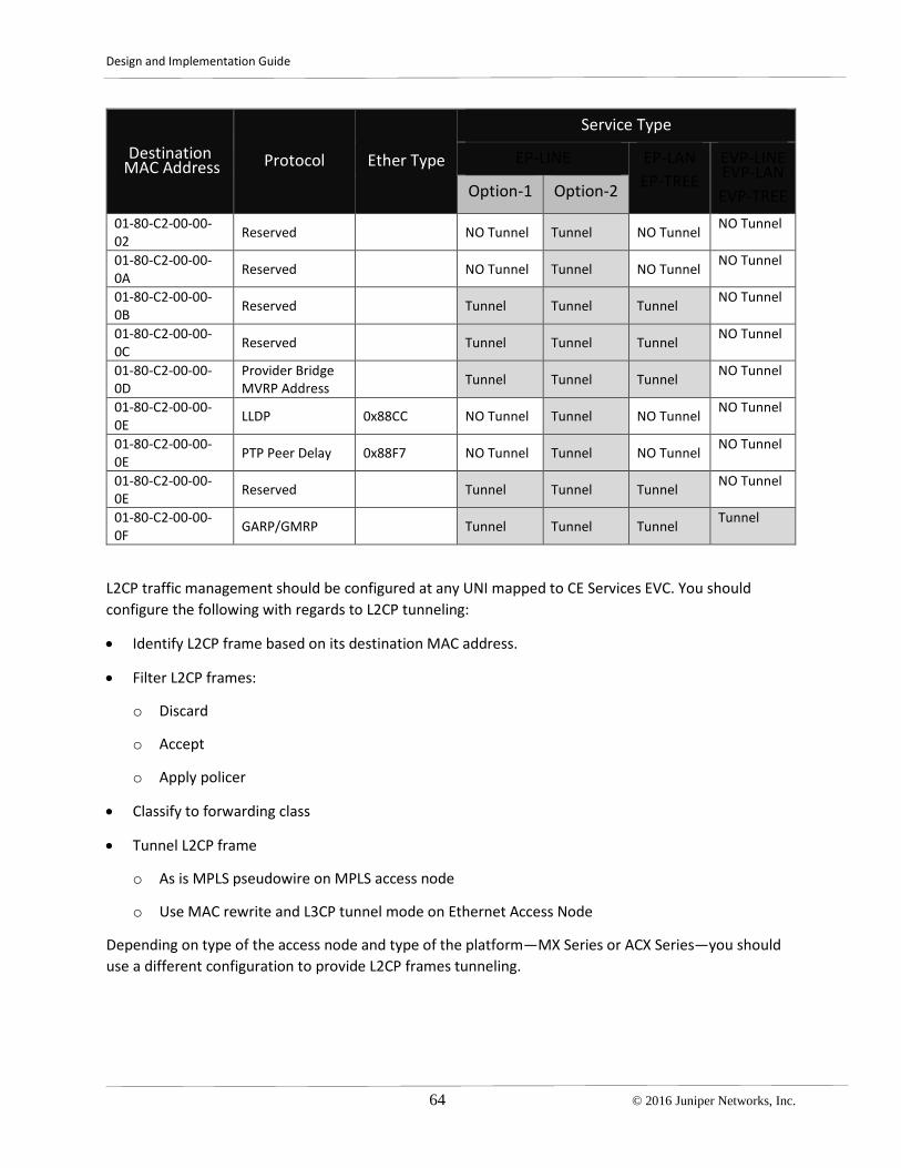
Design and Implementation Guide
64 © 2016 Juniper Networks, Inc.
Destination MAC Address Protocol Ether Type
Service Type
EP-LINE EP-LAN EP-TREE
EVP-LINE EVP-LAN EVP-TREE Option-1 Option-2
01-80-C2-00-00-02 Reserved NO Tunnel Tunnel NO Tunnel NO Tunnel
01-80-C2-00-00-0A Reserved NO Tunnel Tunnel NO Tunnel NO Tunnel
01-80-C2-00-00-0B Reserved Tunnel Tunnel Tunnel NO Tunnel
01-80-C2-00-00-0C Reserved Tunnel Tunnel Tunnel NO Tunnel
01-80-C2-00-00-0D
Provider Bridge MVRP Address Tunnel Tunnel Tunnel NO Tunnel
01-80-C2-00-00-0E LLDP 0x88CC NO Tunnel Tunnel NO Tunnel NO Tunnel
01-80-C2-00-00-0E PTP Peer Delay 0x88F7 NO Tunnel Tunnel NO Tunnel NO Tunnel
01-80-C2-00-00-0E Reserved Tunnel Tunnel Tunnel NO Tunnel
01-80-C2-00-00-0F GARP/GMRP Tunnel Tunnel Tunnel Tunnel
L2CP traffic management should be configured at any UNI mapped to CE Services EVC. You should configure the following with regards to L2CP tunneling:
• Identify L2CP frame based on its destination MAC address.
• Filter L2CP frames:
o Discard
o Accept
o Apply policer
• Classify to forwarding class
• Tunnel L2CP frame
o As is MPLS pseudowire on MPLS access node
o Use MAC rewrite and L3CP tunnel mode on Ethernet Access Node
Depending on type of the access node and type of the platform—MX Series or ACX Series—you should use a different configuration to provide L2CP frames tunneling.

Design and Implementation Guide
© 2016 Juniper Networks, Inc. 65
MX Series Router as VPLS or MPLS Access Node Configure the UNI of an access node with input filters, use appropriate match conditions based on the destination MAC address in multifield (MF) classifiers to drop, forward and send L2CP traffic to the appropriate forwarding class. Add a bandwidth policer as an action to the same filter to restrict bandwidth availablity for the customer L2CP control frames.
ACX Router as Ethernet Access Node If the ACX router serves as an Ethernet access node, then to tunnel customer L2CP frames enable a special tunnel mode at the UNI interface of the access node. Otherwise, the ACX router will attempt to actively participate in L2CP peering with the customer CPE device. Also, you can use input filters with an MF classifier to send L2CP traffic to the proper forwarding class (see Customer L2CP Frames Classification). You may also restrict bandwidth by adding a policer for the filter. However, the ACX router has already implemented internal filters that set the maximum available bandwidth thresholds for different types of the L2CP traffic that works in most deployment scenarios.
ACX Router as MPLS Access Node As of Junos 12.3.X54.S4, ACX series routers support matching conditions based on destination MAC address for family ccc filters. That means that all L2CP traffic will be forwarded through the EVC as a regular Ethernet frame. Configure the UNI of an access node with input filters that use appropriate match conditions based on destination MAC address and multifield (MF) classifiers to drop, forward, and send L2CP traffic to the appropriate forwarding class. Add bandwidth policer as an action to the same filter to restrict bandwidth available for the customer L2CP control frames.
For COS design consideration with regards to L2CP see Customer L2CP Frames Classification.


Design and Implementation Guide
© 2016 Juniper Networks, Inc. 67
Chapter 9 CoS Planning for Metro Ethernet Services
This document combines common design considerations that should be followed for any of the use cases with some specific COS requirement for MBH, Carrier Ethernet service, Layer 3 Business Access, and Residential aggregation use cases.
General Notes about CoS Management on Junos Platforms Before assigning any bandwidth profile to a service node (SN) object—Layer 2 or Layer 3 UNI, forwarding table, Layer 2 EVC—the SN must recognize the CoS assigned to the packet, remark packets if required, prioritize packets, and apply CoS rules to the traffic streams.
At the ingress interface, configure a classifier that allows sending packets to the appropriate forwarding class and assigning to the packet appropriate color or priority-loss. Priority-loss has global significance within the router.
Once a CoS classifier is applied at the ingress interface, it stays the same while the packet transits through the router. You can change the loss priority by applying a filter (that you may think as access-list) or policer at ingress, egress interface or even routing instance. Junos keeps track of the frame color by using loss-priority parameter which can take value of low, medium-high or high and corresponds to Green, Yellow and Red color in MEF definitions.
Figure 39 shows the types of CoS marking that differentiates traffic streams. Packet classification at the ingress interface is based on the 802.1p priority bit, IP DSCP, MPLS EXP bit, or on base of the UNI or EVC, when all traffic from the logical or physical interface can be mapped to one of eight forwarding classes and one of two loss-priorities. Once the packet has been assigned a forwarding class and loss priority, it then be assigned an appropriate bandwidth profile (BWP).
Figure 39 Supported COS identifiers
Typically, behavior aggregate (BA) classifiers are used together with schedulers to achieve the required CoS guarantees in a network. However, using a combination of BA and multifield (MF) classifiers introduces an extra level of granularity. You can prioritize traffic streams within a particular class on the basis of VLAN IP source addressing.

Design and Implementation Guide
68 © 2016 Juniper Networks, Inc.
In Junos routers, once a packet is sent to a forwarding class it is assigned to a traffic queue that is served at router interfaces according to special rules that are defined by schedulers, schedulers-maps or traffic-control profiles. These rules define the shaping rate of the specific queue and how to manage traffic in different queues in case of traffic congestion on an interface. The following tools on Junos routers can be used to define these rules:
• Traffic queue priority
• Available bandwidth and buffer space at physical and logical interfaces
• Shaping rate per queue
• Hierarchy (H-CoS)
When you configure CoS classification and rewrite rules, you assign each packet to a forwarding class. In the deployment scenarios in this guide, each network node provides eight forwarding classes at each physical UNI and NNI port. Each forwarding class is mapped to one of eight queues, and each queue can be assigned a priority. Priority, in turn, defines how traffic in the queue is scheduled. Higher-priority queues are serviced before lower-priority queues in a weighted round-robin fashion. MX Series and ACX Series routers have some differences in the way they assign and serve queue priorities.
MX Series routers use the following definitions:
• Strict-high—The highest priority level. Traffic in this queue does not have any bandwidth limitations and is restricted only by physical port bandwidth. This traffic is always serviced before any other queue receives bandwidth. While there is traffic in the queue, strict-high traffic is serviced first along with the in-contract high priority queues. Only one strict-high priority queue can be assigned at one time.
• High—This queue has the same priority level as strict-high. However, traffic in this queue is restricted by the committed information rate (CIR). While traffic load is below the configured CIR bandwidth, it is served first or in a weighted round-robin fashion with strict-high and other high priority queues.
• Medium high—The traffic in this queue is serviced when it is below its CIR and there is not any traffic in the queues with higher priorities. If there are multiple medium-high priority queues, they are served in a weighted round-robin fashion.
• Medium low—The traffic in this queue is serviced when it is below its CIR and there is not any traffic in the queues with higher priorities. If there are multiple medium-low priority queues, they are served in a weighted round-robin fashion.
• Low—The traffic in this queue is served when it is below its CIR and there is not any traffic in the queues with higher priorities. If there are multiple low priority queues, they are served in a weighted round-robin fashion.
ACX Series routers use the following definitions:
• Strict—The highest possible priority level. Traffic in this queue does not have any bandwidth limitations and is restricted only by physical port bandwidth. This traffic is always serviced before

Design and Implementation Guide
© 2016 Juniper Networks, Inc. 69
any other queue. While there is traffic in the queue, strict-priority traffic is serviced first. On ACX series routers, unlike other Junos platforms, multiple queues can be configured with strict-priority at the same time. If several strict-priority queues are in use, the hardware schedulers service the queues in the descending order of their queue numbers.
• High—Although high, medium-high, medium-low, and low priority levels are not explicitly supported on ACX Series routers, this behavior can be achieved by assigning a strict-high priority with a shaping rate. In this guide, we refer to such a configuration on ACX Series routers as a high priority.
• Default weighted deficit round-robin scheduling queue—The traffic in this queue is serviced when it is below its CIR and there is not any traffic in the queues with higher priorities. Although high, medium-high, medium-low, and low priority levels are not supported on ACX Series routers, in this guide, we refer to this priority level as a low priority.
We recommend 5 forwarding classes in the Universal Access and Aggregation network:
forwarding-classes {
class low queue-num 0;
class high queue-num 1;
class medium queue-num 2;
class network-control queue-num 3;
class invalid queue-num 7;
}
Low, medium, high classes are used for customer traffic. The network-control forwarding class is assigned to a dedicated queue used for network-control protocols and management traffic. By default, network-control traffic originates at a Junos router, and is mapped to queue 3 or 0 depending on the protocol. See the Junos Technical Documentation for complete list of protocols and their matching queues.
To maintain uniform control over management traffic bandwidth allocation, we recommend that you direct all host outbound traffic to queue 3. Depending on the situation, the network-control queue can be configured with a different priority. In most cases, it is enough to treat the network-control queue as assured-forward to guaranty some bandwidth to this queue in case of congestion. When your network is used for mobile backhaul and carries an IEEE 1588v2 traffic, which is a part of network-control queue, then strict-high priority should be assigned.
The type of COS-ID that should be used depends on node type and node interface function: ENNI, UNI or core-facing interface. IEEE 802.1p PCP or IP DSCP is the common frame attributes that allow traffic classification along with right COS-ID and corresponding bandwidth profile (BWP) assignment.
The next step that should be configured for each UNI and core facing interface is rewrite-rules. These rules allow setting up appropriate CoS identifiers to the packet at egress depending on what forwarding-class and loss-priority a packet has. Basically, packet header rewrite happens at every node egress interface along the traffic forwarding path. In most cases, only lower-level packet headers are modified. For example, the DSCP field for Layer 3 services—or 802.1p C-VLAN header—for Layer 2 CE Services—

Design and Implementation Guide
70 © 2016 Juniper Networks, Inc.
remains unchanged to preserve customer COS identifier, however, 802.1p header for S-VLAN (in case of the L2 Ethernet Network) or EXP/TC bits (in case of the MPLS Access Network) are modified.
Customer Frame Classification and Scheduling in MAN The Carrier Ethernet services use case leverages, to a great extent, MEF definitions. In most cases the MEF considers services in ideal situations assuming that there is no congestion in the network. Junos allows you to configure sophisticated schemas to manage traffic queuing and shaping. Also MEF recommendations restrict the shaping and queuing tools that can be used for BWP at to two-rate policing (see notes in MEF 10.2). However, setting up appropriate forwarding classes for ingress traffic at the UNI and defining their priorities at core facing interfaces is mandatory for any carrier grade network. In a real network, you should always take precautions to avoid traffic loss at least for high priority services in case of congestion.
As mentioned, the type of COS-ID that should be used depends on node type and node interface function: ENNI, UNI, or core-facing interface. IEEE 802.1p PCP or IP DSCP are the common frame attributes that allow traffic classification with further assignment of the BWP. This is a traffic policer in Junos. However, the MEF specifies additional methods for traffic classification where COS-ID is based on EVC or Operator Virtual Connection End Point (OVC EP) identifier.
To synchronize CoS and BW management at the ENNI level, the MEF introduces a special three CoS Label Model—with H, M, L labels (see MEF 23.1)—and defines how to map traffic into these three labels based on PCP, DSCP or EVC/OVC EP. Three forwarding classes low, medium and high are in agreement with the MEF three CoS label model. However, these CoS label have no explicit definition within JUNOS notations. In this document we give some useful configuration templates that show how the CoS labels can be configured in Junos notation.
Table 14 shows the complete set Layer 2, Layer 3, and MPLS CoS identifiers and recommended settings for classifiers at the ingress interface to assign frames with different forwarding classes, MEF CoS label and color notations.
Table 14 CE Services Classifiers and Rewrite Rules
Forwarding class Code Points Egress Queue Parameters
MEF Notation
Loss- Priority
802.1p
IP DSCP MPLS EXP
Priority Queue Number
Bandwidth Percent
COS Label Color
Network control Low High
7 6
CS7 CS6
7 6
High 3 5%
High Low 5 CS5, EF 5 Strict high
1 30% H Green
Medium Low High
3 2
CS3, AF3x CS2, AF2x
3 2
low 2 30% M Green Yellow
Low Low High
1 0
CS1, AF1x 1 low 0 remainder L Green Yellow

Design and Implementation Guide
© 2016 Juniper Networks, Inc. 71
Values for the bandwidth percentage reserved for High, Medium and Low classes are given as an example. Depending on real traffic, profile values can be tuned appropriately. The MEF does not specify how to use the rest of PCP values—4, 6, 7 or 100, 110, and 111 for binary code point values. We recommend using COS-ID values of 6 and 7 for network-control forwarding class and reserve 4 for later use. For example, it can be used in MBH profiles for Mobile network signaling traffic.
For the UNI and ENNI, you should add classifiers that send traffic marked with 4, 6, 7 to the default or invalid forwarding class. This practice avoids a situation when mistakenly marked customer traffic is sent into the wrong forwarding class and affects other high-priority traffic.
Rewrite rules can be specified for the following COS identifiers of packet at egress interface:
• 802.1p outer tag (also referenced here as s-tag),
• 802.1p inner tag (also referenced here as c-tag),
• 802.1ad tag, and
• EXP bit
Figure 40 defines mappings between the S-tag header and MEF CoS Label. These mapping rules should be followed when configuring classifiers at the interfaces.
The following four diagrams represent the full set of classifier and rewrite rules that can be used in this solution.
Figure 40 COS Deployment Scenario 1

Design and Implementation Guide
72 © 2016 Juniper Networks, Inc.
Figure 41 COS Deployment Scenario 2
Figure 42 COS Deployment Scenario 3

Design and Implementation Guide
© 2016 Juniper Networks, Inc. 73
Figure 43 COS Deployment Scenario 4
With some variations these can be easily adapted to any deployment scenario described in Deployment Scenarios and Recommendations. In general there are six types of classifiers, plus one explicit classifier that uses the UNI name as COS-ID, and 5 types of rewrite rules that are summarized in Table 15.
Table 15 Solution Supported Classifiers and Rewrite Rules
Classifiers Rewrite rules
ACX MX ACX MX UNI 802.1p c-tag YES YES YES YES UNI DCSP YES YES - - ENNI 802.1p s-tag YES YES YES YES ENNI 802.1ad s-tag YES YES YES YES NNI MPLS exp YES YES YES YES NNI 802.1p s-tag YES YES YES YES UNI or EVC as COS-ID YES YES - -
Note that configuration for the class-of-service may be slightly different on MX or ACX Series routers.
Customer L2CP Frames Classification According to MEF 23.1 a tunneled subscriber’s L2CP traffic should map to particular CoS Labels depending on CoS model chosen. Classification of the L2CP happens at the UNI interface and uses

Design and Implementation Guide
74 © 2016 Juniper Networks, Inc.
destination MAC address as criteria for traffic setting to the right forwarding class. To achieve that on Junos routers, use Multifield (MF) classifiers in addition to a BA classifier at the ingress UNI. See Table 13 for the list of L2CP MAC addresses according to MEF 6.1, 6.1.1.
The following table defines default mapping of L2CP according to MEF 23.1. When only a single CoS Label is subscribed, L2CP shares this CoS label with data service frames. The M CoS Label is chosen for L2CP whenever available, based on its superior loss performance, and a desire to keep it separate from real-time applications.
Table 16 Customer L2CP Frames Mapping to CoS Label
COS Labels Subscriber Model L2CP Label
H, M, L M H, M M H, L H M, L M
Both MX-series and ACX-series router support MF classifiers, which allow assigning Ethernet Frame to the particular forwarding class based on its destination MAC-address.

Design and Implementation Guide
© 2016 Juniper Networks, Inc. 75
Chapter 10 Bandwidth Profile for Metro-E Services
Defining Bandwidth Profile A bandwidth profile (BWP) is a service attribute of the Carrier Ethernet EVC. According to the MEF, a BWP it is a set of parameters that are applied to a reference point. A reference point could be a UNI or an EVC, or it could be a traffic flow with a specified Class of Service Identifier (COS-ID).
BWP, or traffic policing, enables you to control the maximum rate of traffic sent or received on an interface and also to partition network traffic into multiple priority levels, also known as classes of service. A policer defines a set of traffic rate limits and sets consequences for traffic that does not conform to the configured limits. Packets that do not conform to traffic limits are either discarded or marked with a color.
BWPs are defined by the following parameters:
• Committed Information Rate (CIR)
• Committed Burst Size (CBS)
• Excess Burst Size (EBS)
• Excess Information Rate (EIR)
• Coupling Flag (CF).
• Color Mode (CM)
• Direction—Egress or Ingress.
MEF recommendations define a number of restrictions of what type of BWP profile can be applied to what type of reference points. At the same time, there many scenarios of how BWPs can be arranged based on MEF specifications. Providing configurations for all these scenarios is out of scope of the document.
This guide gives an explicit mapping of notations that are used in Junos to the terms and definitions that are used by MEF recommendations, and explains how to configure and apply BWP to different reference points when you build your Carrier Ethernet Service on Juniper Networks routers. Guidance and configuration templates provided in the document can be easily used as building blocks to comprise real deployment scenarios for bandwidth management of any level of complexity.

Design and Implementation Guide
76 © 2016 Juniper Networks, Inc.
Coupling Flag and Color Mode Consideration Coupling Flag and Color Mode are two of six parameters that uniquely identify the BWP.
• Coupling Flag (CF) MUST have only one of two possible values, 0 or 1.
• Color Mode (CM) MUST have only one of two possible values, “color-blind” or “color-aware.”
The MEF recommends a two color model with two token buckets (one bucket per color) with two types of algorithms to manage overflow tokens.
As shown in Figure 44, the Coupling Flag is set to either 0 or 1. The value for CF controls the volume of Service Frames that are declared Yellow.
• When CF is set to 0, the long term average bit rate of service frames that are declared Yellow is bounded by EIR.
• When CF is set to 1, the long term average bit rate of service frames that are declared Yellow is bounded by CIR + EIR depending on volume of the offered Service Frames that are declared Green.
In both cases the burst size of the Service Frames that are declared Yellow is bounded by EBS.
Figure 44 Two rate policer with two token buckets
In the solution we use three-color-two-rate policers that are compliant with the model where CF is set to 1, which is a default fixed value. For a detailed description of the two bucket algorithm used in Junos, see: http://www.juniper.net/techpubs/en_US/junos16.1/topics/concept/policer-algorithm-dual-token-bucket.html
Junos three-color-two-rate policer can be configured in color-blind or color-aware mode which corresponds to two BWP algorithms defined by the MEF (MEF 10.2). “The Bandwidth Profile algorithm is said to be in color aware mode when each Service Frame already has a level of compliance (i.e., a color) associated with it and that color is taken into account in determining the level of compliance by the Bandwidth Profile algorithm. The Bandwidth Profile algorithm is said to be in color blind mode when the color (if any) already associated with each Service Frame is ignored by the Bandwidth Profile Algorithm.
Design and Implementation Guide
© 2016 Juniper Networks, Inc. 77
Color blind mode support is REQUIRED for Bandwidth Profiles. Color aware mode is OPTIONAL for Bandwidth Profiles. The color mode of operation MUST be determined using the parameter CM.”
Because the three-color-policer CF is fixed to 1, the difference between color-aware and color-blind modes becomes negligible and we are using color blind only in all configuration templates for both ACX and MX series platforms. Color blind means that the policer ignores the color of the ingress frame, but still keeps three colors marking schema for frames at egress.
When you need to configure a BWP that differentiates between Yellow and Green frames, use a configuration template where color awareness is configured at the firewall filter level.
On MX series routers you can also configure your system to work as if its policer is set up with CF=0.
Bandwidth parameters: CIR, EIR, CBS and EBS After packet classification is defined we can proceed to setting up a BWP. According to the MEF the BWP algorithm is governed by the six parameters: CIR, CBS, EIR, EBS, CF, and CM.
The parameters comprising the BWP parameters are:
• Committed Information Rate (CIR) expressed as bits per second. CIR MUST be ≥ 0.
• Committed Burst Size (CBS) expressed as bytes. When CIR > 0, CBS MUST be greater than or equal to the largest Maximum Transmission Unit size among all of the EVCs that the Bandwidth Profile applies to. See Section 6.10.
• Excess Information Rate (EIR) expressed as bits per second. EIR MUST be ≥ 0.
• Excess Burst Size (EBS) expressed as bytes. When EIR > 0, EBS MUST be greater than or equal to the largest Maximum Transmission Unit size among of all EVCs that Bandwidth Profile applies to. See Section 6.10.
Three-color-two-rate policer is compliant with MEF traffic management algorithm with CF set to 1. However, Junos uses slightly different definitions for bandwidth parameters.
firewall {
three-color-policer p-15m {
action {
loss-priority high then discard;
}
two-rate {
color-blind;
committed-information-rate 15m;
committed-burst-size 13698;
peak-information-rate 15m;
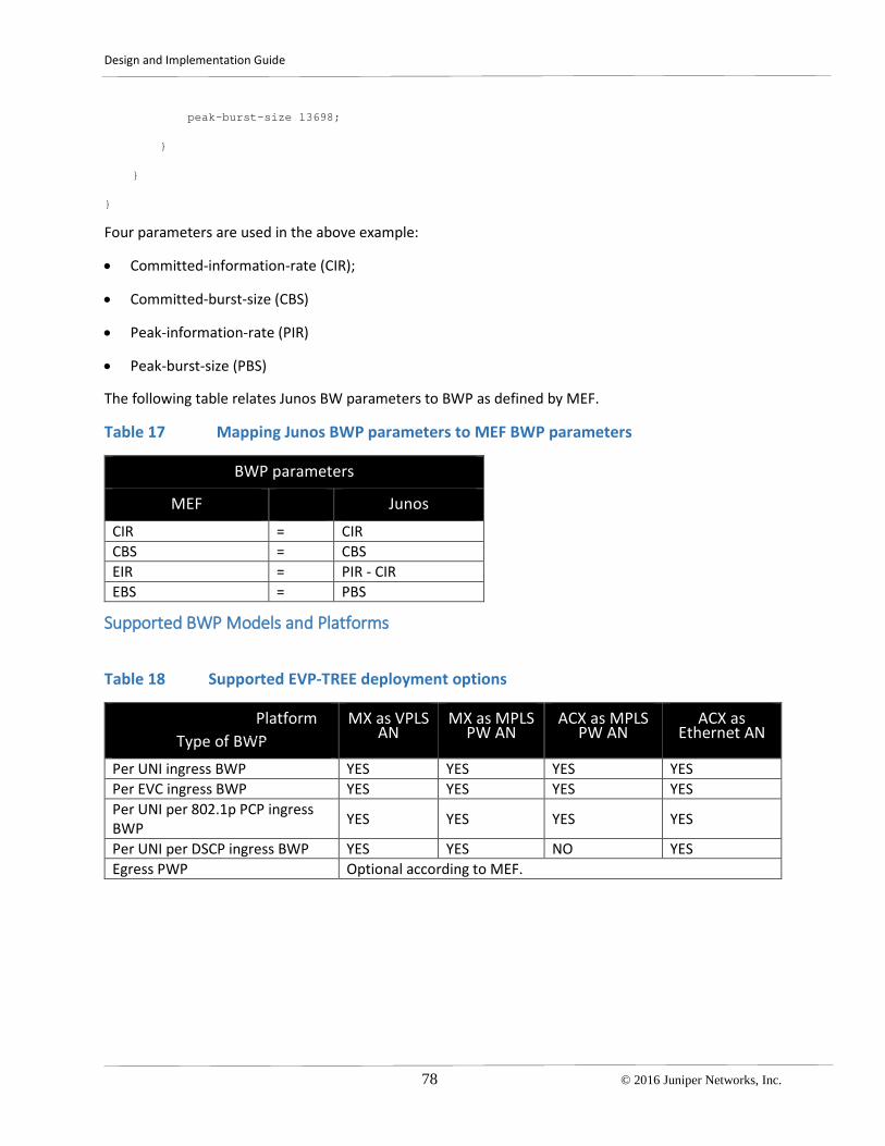
Design and Implementation Guide
78 © 2016 Juniper Networks, Inc.
peak-burst-size 13698;
}
}
}
Four parameters are used in the above example:
• Committed-information-rate (CIR);
• Committed-burst-size (CBS)
• Peak-information-rate (PIR)
• Peak-burst-size (PBS)
The following table relates Junos BW parameters to BWP as defined by MEF.
Table 17 Mapping Junos BWP parameters to MEF BWP parameters
BWP parameters
MEF Junos CIR = CIR CBS = CBS EIR = PIR - CIR EBS = PBS
Supported BWP Models and Platforms
Table 18 Supported EVP-TREE deployment options
Platform Type of BWP
MX as VPLS AN
MX as MPLS PW AN
ACX as MPLS PW AN
ACX as Ethernet AN
Per UNI ingress BWP YES YES YES YES Per EVC ingress BWP YES YES YES YES Per UNI per 802.1p PCP ingress BWP YES YES YES YES
Per UNI per DSCP ingress BWP YES YES NO YES Egress PWP Optional according to MEF.

Design and Implementation Guide
© 2016 Juniper Networks, Inc. 79
Chapter 11 Infrastructure Security Design and Considerations
Security Considerations Service provider networks are subject to attacks from malicious sources. These attacks can be passive, where a network intruder intercepts data traveling through the network (for example, wiretapping), or active, where an intruder initiates commands to disrupt the normal operation of the network (for example, denial of service attacks or address spoofing). Securing a service provider network involves preventing and monitoring unauthorized access, network misuse, unauthorized network modification, or attacks that result in the denial of network services or network-accessible resources.
This section is not a complete discussion about network security threats and mitigation options. However, it focuses on security techniques that are specific to securing the network infrastructure of the Metro Ethernet Network, and includes the following topics:
• Protecting against unauthorized access
• Protecting against hijacking threats
• Protection against Layer 2 loops
o Design for preventing broadcast storms triggered by the MAN infrastructure
VPLS and H-VPLS
Active/Standby Pseudowire Redundancy
G8032v1/v2
Spanning Tree
o Design for preventing broadcast storms triggered by a customer
Spanning Tree
VPLS Multihoming
Multichassis LAG
EVPN Dual Homing
o Layer 2 loop detecting and blocking
MAC move control
CFM: Control of the malicious OAM flow
o Broadcast Storm Control:
Data Plane: policing BUM traffic
Control Plane DDOS protection

Design and Implementation Guide
80 © 2016 Juniper Networks, Inc.
OAM traffic policing
Protecting Against Unauthorized Access Unauthorized access can be mitigated by implementing the following:
• Limit management access to network elements. These limitations would include physical access as well as network access (for example, loopback filter configuration, TACACS+/RADIUS authorization, and allow or deny expressions for certain user groups).
• Disable all control protocols that are not in use.
• Implement secure communication for management access. The secure communication can be in the form of the following:
o Secure shell (SSH)—Devices in this solution support the SSH protocol as a secure alternative to Telnet for system administration.
o Secure Copy (SCP)—Based on the SSH protocol, SCP file transfer securely and reliably transfers files between a local host and a remote host or between two remote hosts.
Protecting Against Hijacking Threats When it comes to mitigating hijacking threats, you can configure authentication for most control protocols used in the network (for example, LDP, ISIS, OSPF, BGP, or RSVP-TE). However, the most complex security threats to manage are denial of service attacks that target the control plane of a network element. UNI connection is the most vulnerable location for these attacks.
For example, an excessive rate of legitimate host-bound packets coming from a user can affect the processing of other user requests and eventually result in the tearing down of control or routing protocol sessions that ultimately lead to traffic loss. This type of failure is not necessarily caused by intruders, but can cause by a misconfiguration in the network.
Another example is a large number of legitimate Ethernet frames with different source MAC addresses coming from a UNI sooner or later will exhaust the limit of the Layer 2 MAC learning table of the metro PE, and cause a mass unknown unicast flooding that will affect all services in a Layer 2 broadcast domain.
Control Plane DDOS Protection MX series routers have built-in (and sometimes unconfigurable) control plane protection mechanisms that operate at different levels. These protection mechanisms are contained in the Routing Engine, the line card host processor, and the network processor. Juniper MX technology supports probably the broadest control plane protection mechanism in the industry, able to handle not only this type of situation but also broader system protection challenges such as DDoS attacks.
DDoS protection is enabled by default for all supported protocol groups and packet types. Default values are present for bandwidth, bandwidth scale, burst, burst scale, priority, and recovery time. You can change the DDoS configuration for individual packet types within a protocol group or for the aggregate

Design and Implementation Guide
© 2016 Juniper Networks, Inc. 81
policer for the protocol group. You can also fine-tune monitoring of DDoS events by configuring tracing operations.
In general, it is relatively difficult to launch an attack from a single end-point, served from one line card, that would affect a user served from a different line card. Thus, we recommend that you isolate failure domains by distributing multiple UNIs between several line cards.
CFM Traffic Policing ACX series routers do not have the same advanced DDOS protection as MX series platforms. In this case, you can apply an individual policer at the UNI or at the Ethernet OAM protocol hierarchy level to restrict the rate of CFM packets hitting local host. This same technique is available on MX series routers as well.
In the Wholesale Mobile Backhaul section, we discussed a case of the wholesale MBH for dual E-Line scenarios. An end-to-end connectivity along the EVC is controlled by the CFM protocol. A centrally located Metro PE router can have thousands of CFM sessions from the cell sites. It is recommended that you deploy CFM traffic policing to avoid a DOS-like failure of the router control plane. Policing can be enabled by applying a standard two rate policer within the configuration of the Ethernet OAM fault and connectivity management. Policers can be applied either globally, per maintenance domain, or per individual OAM session basis.
Restricting the Size of MAC Learning Tables Layer 2 MAC address and VLAN learning and forwarding properties are enabled by default Layer 2 bridging. Unicast MAC addresses are learned to avoid flooding the packets to all ports in a VLAN. A source MAC entry is created in its source and destination MAC tables for each MAC address learned from packets received on ports that belong to the VLAN.
By default, Layer 2 address learning is enabled. You can disable MAC learning for a device or for a specific VLAN or logical interfaces. You can also configure the following Layer 2 forwarding properties:
• Timeout interval for MAC entries
• MAC accounting
• A limit to the number of MAC addresses learned from the logical interfaces
In most cases you do not need to touch the first two parameters but you need to choose the value of the maximum number of MAC addresses that are allowed to be learned and stored in the MAC learning table of the bridge domain or the VPLS routing instance of the access or aggregation node. The MAC limit should be considerably lower than the maximum hardware and software limit of the MAC learning table so that it withstands a MAC address overflow DOS attack. However, it should not be too low because it could affect customer services.
Protecting Against Layer 2 Loops VPLS was the first MPL-based L2 multipoint technology introduced to offer Carrier Ethernet services. With its different variations, either LDP or BGP signaling based, it represents one step forward in preventing broadcast storms, in comparison with a native Ethernet switch environment. But a Layer 2 broadcast storm still could be triggered.
Design and Implementation Guide
82 © 2016 Juniper Networks, Inc.
Infrastructure Triggered Broadcast Storms Infrastructure-triggered broadcast storms are caused inside the network, and can cause a massive network outage. This type of storm can be prevented at the MAN design level.
In native Ethernet switching-based architectures, both infrastructure- and customer-triggered events can happen, with very negative consequences.
Broadcast Storms in VPLS Architectures In VPLS-based architectures infrastructure triggered broadcast storms are not possible because the network is not a L2 network but an IP/MPLS network. The forwarding ultimately is based on a different principle that makes broadcast storms not applicable.
There is no possibility of triggering a Layer 2 loop for hierarchical VPLS (H-VPLS) architecture with a VPLS spoke interconnecting a pair of VPLS Hub. By definition, traffic received by the VPLS hub from the spoke pseudowire is not restricted from being sent to other hub. This fact effectively leads to Layer 2 loop between three nodes: the VPLS spoke and two VPLS hubs. To avoid this situation, we recommend configuring spoke pseudowires in active/standby mode, and only enable the pseudowire status TLV option under the VPLS protocol configuration for the VPLS instance (see Pseudowire Redundancy for T-LDP PW
Broadcast Storms in a Hybrid Architectures In a hybrid network architecture where native Ethernet switching and VPLS are deployed in access and aggregation/core segments respectively, Layer 2 loops are still possible, and you should take precautions at the design level to prevent loop formation. If network is based end-to-end on Juniper platforms, then layer two loop avoidance is provided by Ethernet Ring Protection (ERP)—G8032v1/v2 protocol (see examples in Using G.8032 for Native Ethernet Access Segments and in Using G.8032 with Ethernet-to-VPLS Stitching. If you are using third party access nodes, such as a DSLAM, PON, or EAD, to form an Ethernet access ring, and the access node does not support ERP, an option is to deploy Spanning Tree protocol (STP). The STP domain should be separated from the customer STP domain.
Customer-Triggered Broadcast Storms Customer-triggered broadcast storms are normally caused outside the network, in a badly configured customer connection, or by an unexpected customer connection. Customer-triggered storms can severely affect the service on that customer connection. They can affect other customers, depending on how the network is configured. A common source of customer-triggered broadcast storms are dual-homed CPEs. The most common mechanisms to prevent storms are:
CPE based STP: For dual homed CPEs or even redundant CPEs that have a direct link, using STP is one option. We recommend that you avoid having the STP interact with anything related to the network. The recommended behavior is to transparently tunnel the CE STP BPDUs from one attachment circuit another. From a CPE STP perspective, there will be a physical loop and STP will block one of them, effectively preventing the actual traffic loop to appear. You should either create isolated STP domains per CPE, or enable a common STP domain for all CPEs from the same customers. These strategies will result in a loop free topology. However, the more devices on the same CPE domain the more likely one of them will have an unexpected behavior. Therefore, we recommend that you to keep each STP BDPUs

Design and Implementation Guide
© 2016 Juniper Networks, Inc. 83
confined to its own CPE domain. This would correspond to Metro Ethernet EVC with enabled option for L2CP protocols tunneling (see Tunneling L2CP Traffic).
• BGP based site-id: Both BGP VPLS and [PBB-]EVPN use a similar mechanism to prevent loops while enabling CE dual homing (either active-standby or active-active). In both cases, the fact that the same NLRI is learned from different BGP neighbors but with some different attributes (same site-id with different priority on the BGP VPLS, or same MAC address, same Ethernet Segment Identifier with designated forwarded decision).
• Dual Homed CPE with MC-LAG: On MX Series routers multichassis link aggregation (MC-LAG) enables a device to form a logical LAG interface with two or more other devices. MC-LAG provides benefits over a traditional LAG in terms of node level redundancy, multi-homing support, and loop-free Layer 2 network without running Spanning Tree Protocol (STP) or G.8032. These benefits make this method useful when interconnecting Juniper-based MAN with third party CPEs. MC-LAG can be configured for the VPLS routing instance (see Protecting Dual-homed CPE with MC-LAG), CCC application, and Layer 2 circuit encapsulation types.
• LDP based VPLS does not have a built-in mechanism to prevent customer triggered broadcast storms when it comes to dual-homed CPEs. It is necessary to rely on the CPE running some flavor of Spanning Tree, and its BPDUs being appropriately tunneled through the VPLS instance. It is all very manual and still relies on the basic capabilities of Spanning Tree. We recommend that you deploy this option with active-backup MC-LAG with LACP for state propagation (see Protecting Dual-homed CPE with MC-LAG).
• Newer architectures, such as EVPN, or PBB-EVPN, have introduced mechanisms to enable all-active multi-homed customer connections, without causing a broadcast storm. The architecture principle is not new, but is inherited from legacy technologies, such as ATM LAN Emulation. Essentially, different topologies are built for BUM traffic and known unicast traffic. Known unicast cannot produce, by its nature, a broadcast storm because it never gets replicated. The traffic that causes a broadcast storm (when there is a looped topology) is the BUM. Using BGP signaling with both EVPN and PBB-EVPN creates a loop-free BUM topology, while the unicast topology has all links active, which means it has loops, but those loops will never affect the BUM traffic.
There are cases where customers may have unexpected backdoor links between CEs. Those situations cannot be handled by the mechanisms described above, and will result in customer-triggered broadcast storms.

Design and Implementation Guide
84 © 2016 Juniper Networks, Inc.
Figure 45 F Layer 2 Loop Formed by a Customer’s Backdoor Connection
The following techniques allow you to mitigate consequences of broadcast storms in the service provider metro Ethernet network:
• Broadcast Storm Control:
o Data Plane: Policing BUM traffic
o Control Plane DDOS protection
o OAM traffic policing
• Layer 2 loop detecting and blocking
o MAC move control
o CFM: Control of the malicious OAM flow
Layer 2 Storm Control A traffic storm is generated when messages are broadcast on a network and each message prompts a receiving node to respond by broadcasting its own messages on the network. This, in turn, prompts further responses, creating a snowball effect. The LAN is flooded with packets, creating unnecessary traffic that leads to poor network performance or even a complete loss of network service.
Usually, each customer has limited bandwidth at the UNI that controls the aggregate traffic that it can consume, and limits the overall impact of the broadcast storm. If a customer´s traffic is limited to 200 Mbps and a broadcast storm is triggered by a backdoor link or an improperly configured dual homed CPE, the broadcast storm traffic is limited to 200 Mbps. There may be situations where such a limit does not exist because it is an internal service, like a DSLAM connection, eNodeB, etc. In this case, a broadcast storm will use as much bandwidth as it can, up to 100% of the network utilization.

Design and Implementation Guide
© 2016 Juniper Networks, Inc. 85
If the source of the Layer 2 storms in the Ethernet networks are Layer 2 loops which happened as a result of MAN misconfiguration, adding new access node, adding new links to the network topology then consequences for this can be even more catastrophic.
Storm control enables the network node to monitor traffic levels and to drop broadcast, multicast, and unknown unicast (BUM) packets when a specified traffic level, called the storm control level, is exceeded. Storm control function is supported on both MX and ACX series routers, and should be enabled at all UNI interfaces of the access nodes as well as all service level stitching points at the AGN router.
Control Plane Protection During a Layer 2 Storm In a broadcast storm the control plane will suffer from severe load. The DDOS protection methods as described in Protecting Against Hijacking Threats prevents 100% utilization of the control plane.
With the protection above, the network stays up because the control plane is protected.
MAC Move Control Dual homed CPEs that are not properly configured, unexpected backdoor links between the two, or complex unexpected topologies will cause a circular broadcast storm. The symptoms are heavy MAC move rates and severe service degradation.
It is nearly impossible to use Syslog messages to figure out where the problem is because the MAC moves are identical on all interfaces.
Juniper MX series routers have a mechanism embedded that can be used to detect and act upon this type of situation. You can configure the router to report a MAC address move based on the following parameters:
• Number of times a MAC address move occurs
• Specified period of time over which the MAC address move occurs
Configuration errors can force traffic into never ending circular paths or loops. These loops in the VPLS network cause frequent MAC moves between interfaces that can rectify the problem by disabling the interface. There are certain MACs that can move between different interfaces, for example, mastership change in the Virtual Router Redundancy Protocol (VRRP). The base interface of such MAC moves cannot be maintained because it leads to the assumption of a loop creation. Hence, such MACs should be configured as virtual MACs. Example of virtual MACs are 00:00:5e:00:01:xx for VRRP, 00:00:0c:07:ac:xx for hot standby router protocol (HSRP) , 00:07:b4:00:01:xx for global server load balancing (GSLB), and 02:bf:xx:xx:xx:xx for VMotion.

Design and Implementation Guide
86 © 2016 Juniper Networks, Inc.

Design and Implementation Guide
© 2016 Juniper Networks, Inc. 87
Chapter 12 Providing Resiliency in Metro Ethernet Networks
Resilient Metro Ethernet Networks This section gives recommendations on how to provide resiliency in a metro Ethernet network based on Juniper Network products and technologies. Enabling resiliency is a cornerstone for any carrier grade networks. The Juniper solution includes the following levels of resiliency:
• Redundant hardware (out of scope of the document)
• Software features:
o MPLS FRR, PIC-Edge, IGP LFA (out of scope of the document)
o Pseudowire redundancy
o VPLS Multihoming
o Tail-End protection for PE-CE links
o Ethernet OAM: connectivity and fault management
o Ethernet Ring Protection (ERP) and Spanning Tree
o Multichassis LAG
• Network architecture
o Redundant network topologies in the Access, Aggregation and Core segments
Ring
Full-mesh
Dual Star
o Dual-homed customer CPE
Pseudowire Redundancy for T-LDP PW Target-LDP is the most popular type of point-to-point Layer 2 circuit used in metro access networks with MPLS enabled. Pseudowires being established directly between metro access nodes enables the simplest type of E-Line service. Pseudowires also widely used in the H-VPLS network architecture to enable other types of Metro E services. The most common architecture includes a pair of the VPLS hubs, active and backup, that terminates pseudowires from the access nodes.
Here we explain how to design a network in a multi-homing environment when each access node has more than one pseudowire to interconnect with the aggregation level. This design is based on following functions:
• Targeted LDP pseudowire redundancy

Design and Implementation Guide
88 © 2016 Juniper Networks, Inc.
• Multi-homing VPLS (optional). Not used as part of the solution unless an ACX Series router is used as an access node. This function should be enabled when the AN uses an active/active model for pseudowires terminated at the primary and secondary VPLS hub. As soon as enabled, it is highly recommended to enable and enhance multihoming VPLS mode. See: http://www.juniper.net/techpubs/en_US/junos16.1/topics/example/vpls-multihoming-convergence-example.html.
• Enabling 802.1ag protection for the redundant pair of pseudowires. This is an enhanced version of pseudowire redundancy, which in addition to the LDP control plane, benefits from establishing dedicated OAM sessions between the AN and VPLS hub. This approach may increase stability and decrease restoration time. Also it allows addressing some common failure scenarios. For example, in the case of on isolated VPLS hub, which occurs as a result of all core facing interface failure while spoke to hub connectivity stays up.
• Hot-standby mode pseudowire redundancy. Supported on MX series routers only. Not currently supported on ACX series. (out of scope of the document).
Two common problems are under consideration:
• Avoiding of Layer 2 loops
• Fast and consistent restoration of the end-to-end Layer 2 forwarding path
In the access segments, Layer 2 VPN to VPLS termination (or H-VPLS) scenarios use active and backup pseudowires for stitching point (Router AG1.1 and Router AG1.2) failure protection at the service level. In Figure 46Figure 46, PWs are signaled with targeted LDP and are terminated on the label-switched interfaces (LSIs), which in turn are placed into a VPLS on both Router AG1.1 and Router AG1.2. The LSI interface does not require configuration. Mesh groups should be configured that terminate the PW into VPLS or VSI. See Specifics of VPLS Deployments in the MAN
Either T-LDP or BGP can be used as a signaling for the VPLS instance.

Design and Implementation Guide
© 2016 Juniper Networks, Inc. 89
Figure 46 End-to-End Protection for HSPA Service Profile (H-VPLS Deployment Scenario)
In Figure 46, hot stand-by mode for active and backup PWs with the regular MAC learning process allows consistent and rapid service restoration in case of failure on the AG1 routers. A Layer 2 loop is not forming in this scenario because the active/standby pseudowire model is used and no switching is allowed between active and standby pseudowires.
The following event sequence shows the restoration process after Router AG1.1 fails:
1. Router AG1.1 goes down.
2. Traffic flows from UNI A to the UNI B undergo the following process:
a. The AN1.3 node detects that the active pseudowire is down and switches traffic forwarding to the presignaled backup pseudowire.
b. Router AG1.2 receives a packet from the AN, learns the NodeB MAC address, puts the MAC address into its MAC learning table, and broadcasts the packet to VPLS neighbors as an unknown unicast packet.
c. The remote provider edge router (AG1.n) receives the packet from Router AG1.2 and relearns the MAC address of NodeB; then the AG1.n router maps the MAC address of the CPE at UNI A to Router AG1.2 in their MAC learning tables.
3. Traffic flows from the UNI B to UNI A undergo the following process:
a. The CPE at UNI B sends the packet to the MAC address of the CPE connected to UNI A.
b. Router AG1.n forwards traffic to Router AG1.2 based on updated records in the MAC learning table.
c. Router AG1.2 receives packets, learns the MAC address, puts it into the MAC learning table, and forwards packets to the AN1.3 node over the secondary pseudowire.
A consistent traffic path is installed in both directions.

Design and Implementation Guide
90 © 2016 Juniper Networks, Inc.
Protecting Dual-homed CPE with MC-LAG This section describes a case of providing Metro Ethernet services between end-customer sites that are dual-homed to the service provider MAN access nodes. This scenario is supported only when the CPE is directly connected to MX series routers. This scenario is for service profiles and scenarios described earlier:
• Layer 2 BA with central customer sites dual-homed to AG3 or PE network segments of the Universal Access & Aggregation (UA&A) network
• MBH service profiles with End-to-End H-VPLS and dual-homed MPC at AG2, AG3 or PE segments of the UA&A network.
• Layer 3 BA service profile with centralized business edge, which PE routers dual-homed to AG3 routers of the UA&A network.
• Residential Aggregation service profile with BNG, IMS-PE or VHO dual homed to AG3 routers of the UA&A network.
Figure 47 Dual-Homing Customer CPE with MC-LAG
On MX series routers, multichassis link aggregation (MC-LAG) enables a device to form a logical LAG interface with two or more devices. MC-LAG provides benefits over traditional LAG in terms of node level redundancy, multi-homing support, and loop-free Layer 2 network without running the Spanning Tree Protocol (STP) or G.8032, which makes this method useful when interconnecting a Juniper based MAN with third party CPEs. MC-LAG can be configured for a VPLS routing instance, CCC application, and Layer 2 circuit encapsulation types.
The MC-LAG adjacent devices use the Inter-Chassis Communication Protocol (ICCP) to exchange control information.
As shown in Figure 47, on one end of MC-LAG is a client device (CPE in the figure) that has one or more physical links in a LAG. This client device does not need to be aware of MC-LAG. On the other side of MC-LAG are two MC-LAG devices—AG1 routers. Each of these devices has one or more physical links

Design and Implementation Guide
© 2016 Juniper Networks, Inc. 91
connected to a single client device. The devices coordinate with each other to ensure that data traffic is forwarded properly.
MC-LAG includes the following functionality:
• Active standby mode is supported using Link Aggregation Control Protocol (LACP)
• MC-LAG operates only between two chassis.
• Layer 2 circuit functions are supported with ether-ccc encapsulation.
• VPLS functions are supported with ether-vpls and vlan-vpls.
For a detailed configuration, see: https://www.juniper.net/documentation/en_US/junos16.1/topics/task/configuration/interfaces-configuring-multi-chassis-link-aggregation.html


Design and Implementation Guide
© 2016 Juniper Networks, Inc. 93
Chapter 13 Protection with IEEE G.8032 Protocol
The IEEE G.8032 protocol is used for protection in the Carrier Ethernet access segment to prevent loops in the Ethernet access rings and to provide rapid failure detection and EVC switchover to the alternative path. This method is used as a primary protection mechanism for E-LAN and E-LINE/E-ACCESS services when end-points belong to the Carrier Ethernet access segment. There is a slight difference in the configuration of ring protection depending on the deployment scenaris. Within the current solution are two main scenarios:
• Native Ethernet access.
• Deployment scenarios for CES, which require Ethernet segment stitching with VPLS.
Using G.8032 for Native Ethernet Access Segments The simplest case for setting up G.8032 protection is where the access segment consists of Ethernet nodes only (which may be ACX or MX Series routers), see Figure 48. In this scenario, one of the access nodes is configured as a G.8032 controller and protection link owner. It controls the status of the ring by exchanging G.8032 messages with other members of the ring, and keeps the protected link in blocked status in normal situations, preventing layer 2 loops in the ring. As soon as link failure happens in the ring, the member that detects the link failure sends a G.8032 notification to the protection group controller. The protection ring controller changes the status of the protected link to unblocked, which restores connectivity within the ring. G.8032 detection enforces MAC addresses flashing on each member of the ring, which provides faster service restoration in case of failure detection.
Multiple protection groups can be configured in one physical ring. Each group can have different nodes assigned as group controller and different links configured as protected link. This approach allows arranging of load balancing in the Ethernet ring. Each ring has a dedicated VLAN to exchange G.8032 control traffic, which protects a group of VLANs that carry the actual data traffic.
Figure 48 Deployment Scenario for G.8032 in Ethernet Access Ring

Design and Implementation Guide
94 © 2016 Juniper Networks, Inc.
Using G.8032 with Ethernet-to-VPLS Stitching In these scenarios we assume that Ethernet access half-ring is physically terminated on a pair of aggregation routers—AG1.1 and AG1.2. S-VLANs for E-LAN or E-TREE (see Figure 49), E-LINE or E-ACCESS EVCs (see Figure 50) is terminated into corresponding virtual-switch instance (VSI). Such topology leads to Layer 2 loop and traffic black-holing in case of the link or node failure somewhere in the middle of the access ring. Both issues can be avoided by configuring a G.8032 protection group at Ethernet access nodes (AN-1…x) and aggregation routers (AG1.1 and AG1.2). See Figure 49 and Figure 50.
Figure 49 illustrates the configuration for this scenario. AN and AGG routers should be configured with dedicated VLAN and bridge domains for the G.8032 control channel. In a multi-ring topology where one pair of AGG routers aggregates more than one access ring, each access ring should be configured with its own G.8032 control channel, so one VLAN identifier (or two VLAN identifiers if load balancing is required) should be reserved per access ring.
Figure 49 Scenario for G.8032 Ethernet-to-VPLS Stitching for E-LAN or E-TREE
An enhanced version of the G.8032v2 protocol is supported by the MX series (after Junos 14.1) and on ACX5K platforms. It allows use of the same VLAN identifier for all ring.
As a recommendation, a certain set of VLANs VLAN tag numbers (for example, from 4074-4094) can be reserved for G.8032 control channels, which addresses the needs of the network with up to ten access rings per pair of AGN routers.
Within these deployment scenarios a closed Layer 2 loop exists only for data traffic, but not for the G.8032 control channel, thus the E interface of the AG1.2 router and W interfaces of the AG1.2 router are marked as not used for the protection group.

Design and Implementation Guide
© 2016 Juniper Networks, Inc. 95
Figure 50 Scenario for G.8032 Ethernet-to-VPLS stitching for E-LINE or E-ACCESS
There are two types of Layer 2 loops that can be formed in Figure 49 and Figure 50. The first loop includes all access nodes of the half ring and link between preaggregation routers. The second type of loop is not depicted, but should be taken into account when planning your access and aggregation network. This type of loop can be formed between multiple half rings connected to the same pair of the preaggregation routers. Choosing a G.8032 protected link for each ring prevents both types of Layer 2 loops.
For the scenarios depicted in Figure 50 for the E-LINE or E-ACCESS case, there is no way a link failure in the Ethernet access ring can be detected in the aggregation MPLS segment. Thus, there is no trigger that can be used to initiate active to backup pseudowire switchover. With Layer 2 connectivity over VPLS between AG1.1 and AG1.2, we have a valid forwarding path for any link failure scenario to avoid traffic black-holing.
To provide load balancing in the access ring, configure two protection groups and distribute all VLANs in the ring between these two groups. Configure AG1.1 as the protected link owner in one group and AG1.2 in another.
Remote End Failure Detection Signaling via LFM The best example to show how remote end failure detection and signaling to the customer CPE can be used is the wholesale MBH case. In this scenario, PE routers of the mobile packet core of the mobile provider network are interconnected with multiple—essentially thousands—of cell site switches or routers via dual-home E-lines. In a common scenario, an 802.1ag CFM session is established between the cell site and PE routers, which allows controlling the status of the E-line end-to-end and triggering switchover to the secondary Ethernet connection if the primary goes down. A fundamental problem in this scenario is that number of CFM sessions installed at the mobile core PE are extremely high, thus the

Design and Implementation Guide
96 © 2016 Juniper Networks, Inc.
continuity check interval of the CFM session should be small enough to detect end-to-end failure in the shortest possible time. With thousands CFM sessions connected to single PE routers failure detection can be measured in seconds.
Figure 51 Remote End Failure Detection and Signaling Back via LFM
As an enhancement to this mechanism, metro network access nodes in the service provider network also control connectivity status of the EVC. In some cases, remote end failure, such as Metro PE failure or PE-CE link failure, can be derived from the LDP control plain of the pseudowire that enables E-Line EVC. This type of detection can be much faster. Figure 51 illustrates this scenario.
In case of Metro PE failure or the link between Metro PE and PE1 goes down, the status of the Type 5 pseudowire, encapsulation Ethernet-ccc, can be signaled back to the cell site CPE via LFM protocol (IEEE 802.3ah) or by triggering the interface between the AN and CPE to the down state (see event 1 in the diagram). On MX or ACX Series routers this mechanism can be enabled through the Ethernet OAM action-profile and assigning it to the corresponding physical interface under the link-fault-management configuration hierarchy. Use Junos configuration snippets in 97Table 19 as an example.
The described method can be used with pseudowires using Ethernet-ccc encapsulation. If vlan-ccc encapsulation is used, the AN node can leverage CFM control sessions to detect remote end failure and signal it back via LFM protocol to CPE. However, the same logical scale challenges for the CFM are applicable to the Metro PE as was described above. In this case, see the next proposal, which may significantly improve restoration time down to a sub-second interval and be independent on number of E-line services installed in the central Metro PE.

Design and Implementation Guide
© 2016 Juniper Networks, Inc. 97
Table 19 Configuration Snippet for Remote End Failure Signaling via LFM Action Profile
Pseudowire Tail-end Protection for Metro PE to PE Failure To illustrate how the tail-end protection mechanism can improve restoration time of the Metro-E services we are using the MBH wholesale use case.
In Figure 52, failure of the link between the Metro PE and PE1 routers triggers fast-reroute of the pseudowire frames from the failed Metro PE to the secondary Metro PE. Reroute is based on local repair mechanisms and does not involve control plane interaction between the Metro PEs when the failure occurs; which is why it scales so well and allows true sub-second failure detection and restoration times. Detailed description of PW fast reroute is out of the scope of this document.
Action profile Interface Fault Management protocols {
oam {
ethernet {
link-fault-management {
action-profile <profile-name> {
event {
protocol-down;
}
action {
syslog;
link-down;
send-critical-event;
}
}
}
}
}
}
protocols {
oam {
ethernet {
link-fault-management {
interface interface-name {
apply-action-profile <profile- name>;
}
link-discovery (active | passive);
negotiation-options {
allow-remote-loopback;
no-allow-link-events;
}
pdu-interval interval;
pdu-threshold threshold-value;
remote-loopback;
}
}
}
}
}

Design and Implementation Guide
98 © 2016 Juniper Networks, Inc.
Figure 52 Pseudowire Tail-End Protection of the Metro PE to EPC-PE Link Failure
Fast reroute of the frames gives time to the CFM control plane of the AN and cell site switch to detect failure and trigger traffic to the secondary path. In a real deployment, some additional configuration might be required at the PE1 and PE2 routers of the EPC. Essentially, during a short period of time PE routers should allow and accept traffic that was originally destined to the other PE.

Design and Implementation Guide
© 2016 Juniper Networks, Inc. 99
Chapter 14 OAM
Introducing OAM Operation, Administration, and Maintenance (OAM) refers to a toolset used for detecting and reporting connection failures or measurement of connection performance parameters. OAM was originally used in telephony, and has been adopted in packet based networks. OAM mechanisms are used in various layers in the protocol stack, and are applied to a variety of different protocols.
In some cases, OAM requirements are much broader than Ethernet OAM. They can include general requirements for network management including FCAP network management, and service provisioning and monitoring. As part of the Juniper Metro Ethernet solution, you may benefit from a solution for basic FCAP management, a solution for Zero Touch Deployment, a broad capability for network automation with scripting, configlets provided by Junos Space management platform, network optimization with North Star software, SLA management, or a comprehensive API for OSS/BSS integration provided by the Junos Space platform.
The transport layer for OAM depends on Ethernet-based and MPLS-based OAM tools. The purpose of OAM tools is twofold: to determine the fault in the network, and to isolate and diagnose faults so that corrective action can be taken; for example, redirecting the traffic from a failed path to a backup path and repairing any faults after they have been isolated.
OAM tools and management entities can be deployed at various points in the transport network. A failure can be defined in relation to the requirements, which might be a complete loss of connectivity or partial loss, such as a one-way failure. Also, the failure could be that connection quality drops below a certain threshold.
In this topic, we discuss OAM for active monitoring of active paths in each segment and across each segment in the network. The following list includes the full set of OAM instruments in the network, and maps them to a particular level of the network architecture.
• Segment (access, preaggregation, aggregation, and service edge)
• Intrasegment OAM
• Intersegment OAM
• Network layers (transport and service)
• Ethernet LFM/CFM
• MPLS
• BGP
• Service Level OAM (Layer 2 VPN)

Design and Implementation Guide
100 © 2016 Juniper Networks, Inc.
Ethernet OAM As Ethernet emerged as a carrier-class technology, Ethernet OAM has been developed to ease the OAM of complex Ethernet service provider networks and to lower operational costs. This topic gives a high-level overview of Ethernet OAM, and defines its main functions, such as link fault management, connectivity fault management, and performance monitoring. We also give some examples of how Ethernet OAM can be deployed in the MAN and how they help to solve particular problems. For example, see Remote End Failure Detection Signaling via LFM. Figure 53 illustrates a reference architecture of the Ethernet OAM protocols in the MAN.
Figure 53 Reference Architecture for the Ethernet OAM in MAN
To address the requirements of Ethernet operators, various standardization bodies developed standards for Ethernet OAM to operate at different OAM layers. Table 20shows how the OAM layers, their functions, and corresponding standards work.
Table 20 Ethernet OAM Layers
E-OAM Layers Functions Standards
Service
OAM measures and represents the status of the services as seen by the customer. Metrics such as throughput, round-trip delay, jitter need to be monitored in an effect to meet the Service Level Agreements (SLAs) contracted between the provider and the customer.
ITU-T Y.1731
MEF Specification
Connectivity OAM monitors the communication path between two non-adjacent devices. Although Ethernet is inherently connectionless, there is a need to monitor the
IEEE 802.1ag
ITU-T Y.1731
MEF Specification

Design and Implementation Guide
© 2016 Juniper Networks, Inc. 101
Both MX and ACX Series routers fully support the Ethernet OAM protocols, and are compliant with industry-standard OAM architecture.
Logical scale of the routing platforms used for establishing metro services is crucial for metro PE nodes located at aggregation and metro edge segments. To enable scale, many of the OAM functions like BFD and CFM have been moved out of the Routing Engine and are supported by dedicated demons running on line cards. Thus, adding port-density will not decrease platform OAM capability. Both BFD and CFM allow very aggressive timers.
The following table gives a summary of some key values for Junos based platforms used in the solution.
Table 21 Ethernet OAM Protocols Supported by MX and ACX Series Platforms
Notes:
1. 802.1ag MIP support comes at post FRS 15.1 release on the ACX5K series routers
communication between the two end points, following the same path that the data flows.
Transport
OAM is used to ensure that two directly connected Ethernet peers maintain bidirectional communication. If the link goes down, the transport layer OAM must detect this failure and signal to a higher layer so that the appropriate protocol can route around the failure. Transport-layer OAM must also monitor the quality of the link to ensure that the link performance is acceptable.
IEEE 802.3ah (Now incorporated into IEEE802.3-2005)
Protocol ACX-500/1K/2K/4K ACX5K MX80/104 MX Hi End
LFM YES (server side only)
YES (server side only)
YES (server side only)
YES (server side only)
802.1ag Up MEP YES (family: bridge, ccc)
YES (family: bridge, ccc, vpls)
YES (family: bridge, ccc, vpls)
YES (family: bridge, ccc, vpls)
802.1ag Dn MEP YES (family: bridge, ccc)
YES (family: bridge, ccc, vpls)
YES (family: bridge, ccc, vpls
YES (family: bridge, ccc, vpls)
802.1ag MIP - YES (family: bridge, ccc, vpls1 )
YES (family: bridge, ccc, vpls)
YES (family: bridge, ccc, vpls)
Y.1731 YES (family: bridge, ccc)
YES2 (family: bridge, ccc, vpls)
YES (family: bridge, ccc, vpls)
YES (family: bridge, ccc, vpls)
E-LMI YES (family: bridge, ccc)
YES (family: bridge, ccc, vpls)
YES (family: bridge, ccc, vpls)
YES (family: bridge, ccc, vpls)

Design and Implementation Guide
102 © 2016 Juniper Networks, Inc.
2. ACX5K supports Y.1731 Synthetic Loss Measurement mode only.
Intra-segment OAM The intra-segment of the transport network uses link-level OAM to detect failure within a segment. Because all the links in the transport network are Ethernet, IP, or MPLS, you can use either CFM or BFD to monitor and measure network performance. Both CFM and BFD provide aggressive timers that detect failure in less than a second.
BFD or CFM session connectivity verification can trigger RSVP traffic engineering or LDP failover. The CFM suite provides advanced capabilities, such as packet loss and delay measurement, to determine the health of the link. (See Figure 54.)
In Figure 54 we use CFM (IEEE standard 802.1ag) to check end-to-end data-link layer OAM. For completeness, we have included link fault management (LFM; standard 802.3ah) to show that you can use LFM when your network includes copper links instead of optical links, or when an ACX Series router is connected to a microwave transmission system. In this case, LFM provides fast link failure detection, which is not provided by other techniques. (LFM is not verified as part of the solution.)
At the IGP, transport, and service levels, BFD is used for intra-segment OAM because it provides a single mechanism for detection of forwarding plane-to-forwarding plane connectivity (including links, interfaces, tunnels, and so on). The single mechanism is independent of media, routing protocol, and data protocol; it provides fast convergence of routing protocols, particularly on shared media (Ethernet); and it detects one-way link failures; and does not require changes to existing protocols.
Figure 54 OAM in the Universal Access & Aggregation Network

Design and Implementation Guide
© 2016 Juniper Networks, Inc. 103
Intersegment OAM Inter-segment OAM detects faults in the remote part of the network to redirect traffic as soon as possible and closer to the source, using multi-hop BFD to monitor remote BGP peers. In the event of a BFD session failure, the alternate BGP peer is used.
End-to-end OAM is used to detect the operational capability of remote access devices, and the best way to do so is by using BFD over the LSP. If the BFD session goes down, either the remote CSR has failed or a path to the device through the transport network does not exist. BFD over an LSP provides approximately sub-second failure detection.


Design and Implementation Guide
© 2016 Juniper Networks, Inc. 105
Chapter 15 Inventory of the Network Services
Table 22 contains the full list of service profiles and summarizes types of network service, such as MPLS pseudowire (PW), VPLS, L3VPN, and traditional services, such as E-LINE, E-LAN, E-TREE, enable L3BA, residential aggregation and MBH service profiles.
Network services mapped to the type of customer device (CPE), type of user-to-network interface (UNI) and corresponding service touch. The last two columns relate to the type of remote PE or CPE.
Table 22 Network Services Inventory
Use Case
Service Profile End point A
AN AG1 AG3 PE End Point B
CPE UNI-A UNI-B CPE
MPL
S in
Acc
ess
MBH 4G LTE
Hierarchical L3VPN
eNodeB
Ethernet II or 802.1q
L3VPN L3VPN L3VPN - Ethernet II or 802.1q
EPC-PE L3VPN with PW in Access
PW L3VPN LT-PHT
L3VPN -
H-VPLS PW VPLS VPLS -
MBH HSPA
Hierarchical L3VPN
NodeB Ethernet II or 802.1q
L3VPN L3VPN L3VPN - Ethernet II or 802.1q
RNC or MPC-PE
L3VPN with PW in Access
PW L3VPN LT-PHT
L3VPN -
H-VPLS PW VPLS VPLS -
MBH 3G ATM PWE3 NodeB ATM PWE3 - PWE3 - ATM RNC
MBH 2G
CESoPSN BTS E1 CESoPSN
- CESoPSN
- STM1/4 BSC
SAToP BTS E1 SAToP - SAToP - STM1/4 BSC
PW BTS Ethernet II
PW - PW - Ethernet II or 802.1q
BSC
L3 BA
Distributed L3 in Access (H-PE Profile)
L3 CPE Ethernet II or 802.1q
L3VPN L3VPN - L3VPN
Ethernet II or 802.1q
her
L3 CPE Distributed L3 in AGG PW
L3VPN PS-PHT
- L3VPN
Distributed L3 in AGG PW L3VPN LT-PHT
- L3VPN

Design and Implementation Guide
106 © 2016 Juniper Networks, Inc.
Centralized L3 at L3-PE PW VPLS - L3VPN PS-PHT
Centralized L3 at L3-PE PW VPLS - VPLS-LT L3VPN
DIA
Centralized Profile
L3 CPE Ethernet II or 802.1q
PW VPLS-PW
- PS-HT
Any Inet Host
Centralized Profile PW VPLS - VPLS-LT-L3VPN
L2 BA (Carrier Ethernet)
E-LINE
L2 CPE
Ethernet II or 802.1q
PW - - -
Ethernet II or 802.1q
L2 PE or other L2 CPE
E-LAN PW VPLS - -
E-LAN VPLS - - -
E-TREE PW VPLS - -
E-TREE VPLS
E-ACCESS PW - - -
Use Case
Service Profile End point A
AN AG1 AG3 PE End Point B
CPE UNI-A UNI-B CPE
MPLS
in A
cces
s
L2 Wholesale
E-LINE (MBH Wholesale) CSR
or Cell
PW - PW - Ethernet II or 802.1q
EPC/ RNC/ BSC E-TREE / E-LAN
(MBH Wholesale) PW VPLS VPLS -
E-LINE (L3 BA Wholesale)
L3 CPE
PW - PW -
Ethernet II or 802.1q
L3-PE
E-LINE (DIA Wholesale) PW - PW - INET-PE
E-TREE (L3 BA Wholesale)
PW VPLS VPLS - L3-PE
E-TREE (L3 BA Wholesale)
PW VPLS VPLS - INET-PE
Legacy BA Legacy Legacy CPE
CESoPSN
SAToP
- - ATM/TDM
Legacy CPE

Design and Implementation Guide
© 2016 Juniper Networks, Inc. 107
ATM PWE3
Multicast
Residential IPTV
DSLAM/ OLT/EAD
Ethernet II or 802.1q
L3 PIM P2MP LSP
P2MP LSP
-
802.1q VHO
Business IPTV L3 CPE 802.1ad NG MVPN
NG MVPN
-
Ethe
rnet
in Ac
cess
L3 BA
Distributed L3 in AGG
L3 CPE Ethernet II or 802.1q
802.1ad L3VPN PS-PHT
- L3VPN
Ethernet II or 802.1q
L3 CPE
Distributed L3 in AGG 802.1ad L3VPN LT-PHT
- L3VPN
Centralized L3 at L3-PE 802.1ad VPLS - L3VPN PS-PHT
Centralized L3 at L3-PE 802.1ad VPLS - VPLS-LT L3VPN
DIA
Centralized Profile
L3 CPE Ethernet II or 802.1q
802.1ad VPLS-PW
- PS-PHT Any Inet Host
Centralized Profile 802.1ad VPLS - VPLS-LT-L3 RI
L2 BA (CE Services)
E-LINE
L2 CPE
STB
Ethernet II or 802.1q
802.1ad VPLS - -
Ethernet II or 802.1q
L2 PE E-LAN 802.1ad VPLS - -
E-TREE 802.1ad VPLS - -
E-ACCESS 802.1ad VPLS - -
Multicast
Residential IPTV
DSLAM/ OLT/EAD
Ethernet II or 802.1q
802.1q P2MP LSP
P2MP LSP
- 802.1q
VHO
Business IPTV L3 CPE 802.1q NG MVPN
NG MVPN
- 802.1q
Residential Aggregation Centralized Profile Option A
DSLAM/ OLT/EAD
PW - - - PS-PHT BNG


Design and Implementation Guide
© 2016 Juniper Networks, Inc. 109
Chapter 16 Deployment Scenarios and Recommendations
Deployment Scenarios This chapter contains the following deployment scenarios:
• EVP-LINE Deployment Scenarios
• EP-LAN Deployment Scenarios
• EVP-LAN Deployment Scenarios
• EP-ACCESS Deployment Scenarios
• EVP-ACCESS Deployment Scenarios
• EP-TREE Deployment Scenarios
• EVP-TREE Deployment Scenarios

Design and Implementation Guide
110 © 2016 Juniper Networks, Inc.
EP-LINE Deployment Scenarios EP-LINE service can be originated or terminated on any type of access node, such as MPLS AN, VPLS AN or Ethernet AN, which leads to a number of scenarios supported by Juniper Carrier Ethernet services solution for EP-LINE service. Scenarios are summarized in the following table:
Table 23 Supported EP-Line Deployment Options
UNI A UNI B
MX as VPLS AN
MX as Ethernet AN
ACX as MPLS PW AN
ACX as Ethernet AN
MX as VPLS AN N/A N/A N/A N/A MX as Ethernet AN N/A YES YES YES
ACX as MPLS PW AN N/A YES YES YES
ACX as Ethernet AN N/A YES YES YES
Note: N/A stands for Not Applicable.
Four EP-LINE scenarios are described in the following sections:
• EP-LINE with one native Ethernet segment
• EP-LINE with end-to-end MPLS PW
• EP-LINE with Ethernet to MPLS PW stitching at the preaggregation router
• EP-LINE with Ethernet to VPLS Termination
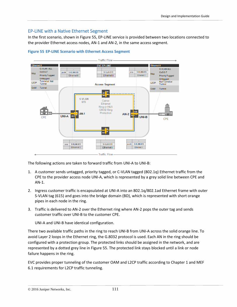
Design and Implementation Guide
© 2016 Juniper Networks, Inc. 111
EP-LINE with a Native Ethernet Segment In the first scenario, shown in Figure 55, EP-LINE service is provided between two locations connected to the provider Ethernet access nodes, AN-1 and AN-2, in the same access segment.
Figure 55 EP-LINE Scenario with Ethernet Access Segment
The following actions are taken to forward traffic from UNI-A to UNI-B:
1. A customer sends untagged, priority tagged, or C-VLAN tagged (802.1q) Ethernet traffic from the CPE to the provider access node UNI-A, which is represented by a grey solid line between CPE and AN-1.
2. Ingress customer traffic is encapsulated at UNI-A into an 802.1q/802.1ad Ethernet frame with outer S-VLAN tag (615) and goes into the bridge domain (BD), which is represented with short orange pipes in each node in the ring.
3. Traffic is delivered to AN-2 over the Ethernet ring where AN-2 pops the outer tag and sends customer traffic over UNI-B to the customer CPE.
UNI-A and UNI-B have identical configuration.
There two available traffic paths in the ring to reach UNI-B from UNI-A across the solid orange line. To avoid Layer 2 loops in the Ethernet ring, the G.8032 protocol is used. Each AN in the ring should be configured with a protection group. The protected links should be assigned in the network, and are represented by a dotted grey line in Figure 55. The protected link stays blocked until a link or node failure happens in the ring.
EVC provides proper tunneling of the customer OAM and L2CP traffic according to Chapter 1 and MEF 6.1 requirements for L2CP traffic tunneling.

Design and Implementation Guide
112 © 2016 Juniper Networks, Inc.
The following table summarizes the EP-LINE service attributes and variables. Assign actual values before using these attributes in the configuration templates for the scenario.
Table 24 EP-LINE Service Attributes for Ethernet Access Segment
EVC ID EVC MAGENTA EVC TYPE EP-LINE: <EVC-ID>
END POINTs AN-1 <ge|xe-UNI-A>
AN-2 <ge|xe-UNI-B>
EVC stitching at AGG routers N/A N/A
MTU , byte <MTU-ETH> <MTU-ETH> End Point Segment Type Ethernet Ethernet END POINT Property N/A N/A EVC VPLS Instance N/A N/A End-Point VPLS Instance N/A N/A S-VLAN <EVC-S-VLAN> <EVC-S-VLAN> End point PW VC ID N/A N/A C-VLAN-ID 1-4094 1-4094 C-VLAN-ID Preservation YES YES C-VLAN Bundling YES - All to one YES - All to one S-VLAN/EVC Multiplexing NO NO COS preservation YES YES BW Profile Per UNI CIR,PIR,CBS,EBS CIR,PIR,CBS,EBS BW Profile Per EVC/OVC CIR,PIR,CBS,EBS CIR,PIR,CBS,EBS

Design and Implementation Guide
© 2016 Juniper Networks, Inc. 113
EP-LINE with End-to-End MPLS PW Figure 56 shows the second deployment scenario for EP-LINE service provided to the customer CPEs connected to the two MPLS nodes, AN-1 and AN-2 routers, which belong to the same or different MPLS access segments.
Figure 56 EP-LINE Scenario with End-to-End MPLS PW
The following actions are taken to forward traffic from UNI-A to UNI-B:
1. A customer sends untagged, priority tagged or C-VLAN tagged (802.1q) Ethernet traffic from the CPE to the provider access node UNI-A, represented by a grey solid line between the CPE and AN-1.
2. Customer Ethernet traffic is encapsulated at ingress UNI-A into MPLS pseudowire type 5, encapsulation type Ethernet, and tunneled over seamless MPLS to AN-2.
3. The AN-2 node pops the MPLS service label and sends Ethernet frames over UNI-B to the CPE.
Either BGP or LDP can be used to signal end-to-end pseudowire between AN1 and AN-2 nodes in the MAN.
EVC provides proper tunneling of the customer OAM and L2CP traffic as described in Tunneling L2CP Traffic and MEF 6.1 requirements for L2CP traffic tunneling. When you use the ACX router as an MPLS node, additional consideration about L2CP traffic tunneling should be taken in to account as described in Chapter 1.

Design and Implementation Guide
114 © 2016 Juniper Networks, Inc.
If both nodes belong to the same MPLS access segment, additional consideration should be made about the path of the PW between two nodes. There are two options:
• PW takes the shortest path between two access nodes (Fully meshed LSP topology)
• PW takes path through AG router (Hub and spoke LSP topology)
The choice between two options is defined by intra-LSP topology: Full mesh or Hub-and-Spoke LSP topology with AG routers as hub and AN router as spokes.
summarizes the EP-LINE service attributes and variables. Assign actual values before using these attributes in the configuration templates for the scenario.
Table 25 EP-LINE Service Attributes for the End-to-End MPLS PW Scenario
EVC ID EVC RED: <EVC-ID> EVC TYPE EP-LINE
END POINTs AN-1 <ge|xe-UNI-A>
AN-2 <ge|xe-UNI-B>
EVC stitching at AGG routers N/A N/A
MTU , byte <MTU-ETH> <MTU-ETH> End Point Segment Ethernet Ethernet END POINT Property N/A EVC VPLS Instance N/A N/A
End-Point VPLS Instance N/A N/A S-VLAN N/A N/A End point PW VC ID <VC-ID-ACTIVE> <VC-ID-ACTIVE> C-VLAN-ID 1-4094 1-4094 C-VLAN-ID Preservation YES YES C-VLAN Bundling YES – All to One YES – All to one S-VLAN/EVC Multiplexing NO NO COS preservation YES YES BW Profile Per UNI CIR,PIR,CBS,EBS CIR,PIR,CBS,EBS BW Profile Per EVC/OVC CIR,PIR,CBS,EBS CIR,PIR,CBS,EBS

Design and Implementation Guide
© 2016 Juniper Networks, Inc. 115
EP-LINE with Ethernet to MPLS PW Stitching Figure 57 shows the third scenario. The AN-1 router belongs to the L2 Ethernet access segment, and the AN-2 router belongs to the MPLS L2 access segments.
Figure 57 EP-LINE scenario with Ethernet to MPLS PW Stitching
The following actions are taken to forward traffic from UNI-A to UNI-B:
1. Ingress customer traffic is encapsulated at UNI-A into an 802.1q/802.1ad Ethernet frame with outer S-VLAN tag (615) and goes into the bridge domain (BD), which is represented with short orange pipes in each Ethernet access node in the ring.
2. Traffic is delivered to the preaggregation router, either AG1.1 or AG1.2, over the Ethernet ring where it is terminated into VPLS using a virtual-switch routing instance CE20-615-VPLS, which is configured on both AG1.1 and AG1.2.
VPLS stitches the Ethernet access segment and LDP signaled pseudowires of type 4 encapsulation (vlan-Ethernet encapsulation) from MPLS access node AN-2.
3. Traffic is delivered to AN-2, which pops the MPLS service label and the outer VLAN tag, and sends customer traffic over UNI-B to the customer CPE.
There are two available traffic paths between UNI-A and the preaggregation routers shown as a solid orange line in the figure. To avoid a Layer 2 loop and to provide rapid failure detection and forwarding path switchover in the Ethernet ring, the G.8032 protocol is used. Each AN in the ring as well as preaggregation router’s access facing interfaces should be configured with protection group. The protected link should be assigned in the network, and is represented by a dotted grey line in the figure. This link stays blocked until another link or node failure happens in the ring.

Design and Implementation Guide
116 © 2016 Juniper Networks, Inc.
As shown in Figure 57, resiliency in the MPLS segment is provided by an active-backup pair of MPLS pseudowires—virtual-circuit-id 11615 dashed line for backup and virtual-circuit-id 12615 solid line for active pseudowire—established from the AN-2 node to AG1.1 and AG1.2 respectively. For more detailed description of how resiliency provided in the scenario, see Pseudowire Redundancy for T-LDP PW.
Table 26 summarizes the EP-LINE service attributes. Assign actual values before using these attributes in the configuration templates for the scenario.
Table 26 EP-LINE Service Attributes for the Ethernet to PW Stitching Scenario
EVC ID EVC MAGENTA: <EVC-ID> EVC TYPE EP-LINE
END POINTs AN-1 <ge|xe-UNI-A>
AN-2 <ge|xe-UNI-B>
EVC stitching point AG1.1:
<ge|xe-AG1.1-NNI-West>. <AG1.1-EVC-UNIT-ID> AG1.2:
<ge|xe-AG1.2-NNI-East>. <AG1.2-EVC-UNIT-ID>
AG1.1 and AG1.2
MTU , byte <MTU-ETH> <MTU-ETH> End Point Segment Ethernet MPLS END POINT Property EVC VPLS Instance CE20-<EVC-ID>-VPLS CE20-<EVC-ID>-VPLS End-Point VPLS Instance N/A N/A S-VLAN <EVC-S-VLAN> <EVC-S-VLAN>
End point PW VC ID N/A <VC-ID-ACTIVE> <VC-ID-BACKUP>
C-VLAN-ID 1-4094 1-4094 C-VLAN-ID Preservation YES YES C-VLAN Bundling YES – All to one YES – All to one S-VLAN/EVC Multiplexing NO NO COS preservation YES YES BW Profile Per UNI CIR,PIR,CBS,EBS CIR,PIR,CBS,EBS BW Profile Per EVC/OVC CIR,PIR,CBS,EBS CIR,PIR,CBS,EBS

Design and Implementation Guide
© 2016 Juniper Networks, Inc. 117
EP-LINE with Ethernet to VPLS Termination In the fourth scenario for EP-LINE services, AN routers belong to different L2 Ethernet access segments connected through the MPLS-enabled metro aggregation/core segments.
Figure 58 EP-LINE Deployment Scenarios with Ethernet-to-VPLS Stitching
The following actions are taken to forward traffic from UNI-A to UNI-B.
1. Ingress customer traffic is encapsulated at UNI-A into an Ethernet 802.1q/802.1ad frame with outer S-VLAN tag (615) and goes into the bridge domain (BD), which is represented with short orange pipes in each Ethernet access node in the ring.
2. Traffic is delivered to the preaggregation router, either AG1.1 or AG1.2, over the Ethernet ring where it is terminated into VPLS. The virtual-switch routing instance CE20-615-VPLS is represented by solid blue lines in the figure, and is configured on all preaggregation routers at both ends of the MPLS segment.
VPLS stitches the Ethernet access segment at both ends of the MPLS segment.
3. From AG1.1 and AG1.2, customer Ethernet frames are encapsulated with a VPLS service label, and are delivered to the other end of the MPLS segment to either the AG1.3 or AG1.4 router.
The exact traffic forwarding path is not predetermined, and is defined by the MAC learning mechanism in the VPLS bridge domain.
4. The AG1.3 router pops the MPLS service label and sends the traffic into Ethernet access segment on the right with the same outer S-VLAN tag (615) as in the original AN-1 node.

Design and Implementation Guide
118 © 2016 Juniper Networks, Inc.
5. Traffic is delivered over the Ethernet access ring to the AN-2 node, which pops the outer S-VLAN tag and sends traffic to the customer CPE.
There are two available traffic paths in each Ethernet access segment to the preaggregation routers shown with a solid orange line in Figure 58. To avoid Layer 2 loops and to provide rapid failure detection and forwarding path switchover in the Ethernet ring, the G.8032 protocol is used. Each AN in the ring as well as preaggregation router’s access facing interfaces should be configured with a protection group. The protected links should be assigned in the network, and are represented by a dotted grey line in Figure 58. The protected link stays blocked until a link or node failure happens in the ring.
The following table summarizes the EP-LINE service attributes. Assign actual values before using these attributes in the configuration templates for the scenario.
Table 27 EP-LINE Service Attributes for the Ethernet-to-VPLS Stitching Scenario
EVC ID EVC MAGENTA EVC TYPE EP-LINE: <EVC-ID>
END POINTs <AN-1-ID> <ge|xe-UNI-A>
<AN-2-ID> [ge|xe-<AUNI-B>]
EVC Stitching point AG1.1:
<ge|xe-AG1.1-NNI-West>. <AG1.1-EVC-UNIT-ID>
AG1.2: <ge|xe-AG1.2-NNI-East>. <AG1.2-EVC-UNIT-ID>
AG2.1: <ge|xe-AG2.1-NNI-West>. <AG2.1-EVC-UNIT-ID>
AG2.2: <ge|xe-AG2.2-NNI-East>. <AG2.2-EVC-UNIT-ID>
MTU , byte <MTU-ETH> <MTU-ETH> End Point Segment Ethernet Ethernet END POINT Property EVC VPLS Instance CE20-<EVC-ID>-VPLS CE20-<EVC-ID>-VPLS End-Point VPLS Instance N/A N/A S-VLAN <EVC-S-VLAN> <EVC-S-VLAN> End point PW VC ID N/A N/A C-VLAN-ID 1-4094 1-4094 C-VLAN-ID Preservation YES YES C-VLAN Bundling YES - All in one YES – All in one S-VLAN/EVC Multiplexing No No COS preservation YES YES BW Profile Per UNI CIR,PIR,CBS,EBS CIR,PIR,CBS,EBS BW Profile Per EVC/OVC CIR,PIR,CBS,EBS CIR,PIR,CBS,EBS

Design and Implementation Guide
© 2016 Juniper Networks, Inc. 119
EVP-LINE Deployment Scenarios EVP-LINE services can be originated or terminated on the logical interface of an access node, such as an MPLS, VPLS, or Ethernet AN, that leads to a number of scenarios supported by Juniper CE Services Solution for EVP-LINE service. Scenarios are summarized in the following table:
Table 28 Supported EVP-Line Deployment Options
UNI A
UNI B
MX as VPLS AN
MX as Ethernet AN
ACX as MPLS PW AN
ACX as Ethernet AN
MX as VPLS AN N/A N/A N/A N/A MX as Ethernet AN N/A YES YES YES ACX as MPLS PW AN N/A YES YES YES
ACX as Ethernet AN N/A YES YES YES Note: N/A stands for Not Applicable.
Four EVP-LINE scenarios are described in the following sections:
• EVP-LINE between access nodes in one Ethernet segment
• EVP-LINE between two MPLS access nodes
• EVP-LINE between Ethernet AN and MPLS AN with stitching at the preaggregation router
• EVP-LINE between to Ethernet ANs located in different Ethernet segment connected over MPLS aggregation network

Design and Implementation Guide
120 © 2016 Juniper Networks, Inc.
EVP-LINE within a Native Ethernet Segment In the first scenario, EP-LINE service is provided between two locations connected to the provider Ethernet access nodes, AN-1 and AN-2, in the same access segment.
Figure 59 EVP-LINE Deployment Scenarios in Ethernet Access Segment
The following actions are taken to forward traffic from UNI-A to UNI-B.
1. A customer sends C-VLAN tagged (802.1q) traffic from the CPE to the provider access node UNI-A, which is represented by the solid red line between the CPE and AN-1.
More than one C-VLAN can be mapped to the EVC with one S-VLAN tag that corresponds to the bundling attribute of the Ethernet service (see Table 29). The UNI logical unit should be configured with the vlan-id list <C-VLAN list> statements. Also, more than one EVP-LINE EVC can be mapped to the UNI, which correspond to S-VLAN multiplexing attribute (see Table 29).
2. Each EVC should be assigned a unique S-VLAN tag across the MAN or across the closed Layer 2 segment of the MAN (see S-VLAN Translation of the EVC between Ethernet Rings) and mapped to its own set of C-VLANs. This traffic is also encapsulated at UNI-A into an 802.1ad Ethernet frame with the outer S-VLAN tag (605) and goes into the bridge domain (BD)—represented with short orange pipes in each node in the ring—at the AN-1 node.
3. Traffic is delivered to the AN-2 node over the Ethernet ring where AN-2 pops the outer tag and sends customer traffic over UNI-B to the CPE. Both UNI-A and UNI-B have identical configuration.
There two available traffic paths in the ring to reach UNI-B from UNI-A—solid orange line. To avoid a Layer 2 loop in the Ethernet ring, G.8032 protocol is used. Each AN in the ring should be configured with a protection group. The protected link should be assigned in the network—represented by a dotted grey line in Figure 59—which stays blocked until a link or node failure happens in the ring.

Design and Implementation Guide
© 2016 Juniper Networks, Inc. 121
EVC provides proper tunneling of the customer OAM traffic and drops any L2CP according to the description in Tunneling L2CP Traffic and MEF 6.1 requirements for L2CP traffic tunneling.
The following table summarizes the EVP-LINE service attributes. Assign actual values before using these attributes in the configuration templates for the scenario.
Table 29 EVP-LINE Service Attributes for Ethernet Access Segment
EVC ID EVC YELLOW:<EVC-ID> EVC TYPE EVP-LINE
END POINTs AN-1 [ge|xe-<UNI-A>] . <EVC-UNIT-ID>
AN-2 [ge|xe-<UNI-B>] . <EVC-UNIT-ID>
EVC stitching point N/A N/A UNI MTU , byte <MTU-LAN> <MTU-LAN> End Point Segment Ethernet Ethernet END POINT Property EVC VPLS Instance N/A N/A End-Point VPLS Instance N/A N/A S-VLAN <EVC-S-VLAN> <EVC-S-VLAN> End point PW VC ID N/A N/A C-VLAN-ID <C-VLANs> <C-VLANs> C-VLAN-ID Preservation YES YES C-VLAN Bundling YES YES S-VLAN/EVC Multiplexing YES YES COS preservation YES YES BW Profile Per UNI CIR,PIR,CBS,EBS CIR,PIR,CBS,EBS BW Profile Per EVC/OVC CIR,PIR,CBS,EBS CIR,PIR,CBS,EBS

Design and Implementation Guide
122 © 2016 Juniper Networks, Inc.
EVP-LINE with End-to-End MPLS PW Figure 60 represents the second deployment scenario for EP-LINE service provided to the customer CPEs connected to the AN-1 and AN-2 MPLS nodes that belong to the same or different MPLS access segments.
Figure 60 EVP-LINE Deployment Scenarios with End-to-End MPLS PW
The following actions are taken to forward traffic from UNI-A to UNI-B:
1. The customer sends C-VLAN tagged (802.1q) traffic from the CPE to the UNI-A access node, represented by the solid red line between the CPE and AN-1.
2. AN-1 encapsulates customer Ethernet traffic at the ingress of UNI-A into MPLS pseudowire type 4 (encapsulation type VLAN-Ethernet).
3. Traffic that originates at the UNI logical unit is tunneled over the seamless MPLS access and aggregation network to AN-2. AN-2 pops the MPLS service label and sends Ethernet frames over UNI-B to the CPE.
More than one C-VLAN can be mapped to the EVC pseudowire, which corresponds to bundling an attribute of the Ethernet service (see Table 30). The logical unit at the UNI interface should be configured with the vlan-id range <C-VLAN list> statement. Also more than one EVP-LINE EVC can be mapped to a UNI, which can be achieved with multiple logical unit configurations at the same UNI, and which corresponds to the EVC multiplexing attribute (see Table 30).
In this scenario EVC provides proper tunneling of the customer OAM and drops L2CP traffic according to the description in Tunneling L2CP Traffic and MEF 6.1 requirements for L2CP traffic tunneling.

Design and Implementation Guide
© 2016 Juniper Networks, Inc. 123
If both nodes belong to the same MPLS access segment, additional consideration should be made about the path of the PW between two nodes. There are two available options:
• PW takes the shortest path between two access nodes (Fully meshed LSP topology)
• PW takes path through AG router (Hub and Spoke LSP topology)
The choice between the two options is defined by intra-LSP topology: Full mesh or Hub-and-Spoke LSP topology with AG routers as hub and AN router as spokes. For examples how to arrange your intra-
LSP infrastructure see the Universal Access and Aggregation Mobile Backhaul Design and Implementation Guide
Table 30 summarizes the EVP-LINE service attributes. Assign actual values before using these attributes in the configuration templates for the scenario.
Table 30 EVP-LINE Service Attributes for the End-to-End MPLS PW Scenario
EVC ID EVC RED: <EVC-ID> EVC TYPE EVP-LINE
END POINTs AN-1 ge|xe-<UNI-A>.<EVC-UNIT-ID>
AN-2 ge|xe-<UNI-B>.<EVC-UNIT-ID>
EVC stitching at AGG routers N/A N/A
UNI MTU , byte <MTU-LAN> <MTU-LAN> End Point Segment MPLS MPLS END POINT Property N/A N/A EVC VPLS Instance N/A N/A End-Point VPLS Instance N/A N/A S-VLAN N/A N/A End point PW VC ID <VC-ID-ACTIVE> <VC-ID-ACTIVE> C-VLAN-ID <C-VLANs> <C-VLANs> C-VLAN-ID Preservation YES YES C-VLAN Bundling YES YES S-VLAN/EVC Multiplexing YES YES COS preservation YES YES BW Profile Per UNI CIR,PIR,CBS,EBS CIR,PIR,CBS,EBS BW Profile Per EVC/OVC CIR,PIR,CBS,EBS CIR,PIR,CBS,EBS

Design and Implementation Guide
124 © 2016 Juniper Networks, Inc.
EVP-LINE with Ethernet to MPLS PW Stitching Figure 61 represents the third deployment scenario where the AN-1 router belongs to the L2 Ethernet access segment and the AN-2 router belongs to the MPLS L2 access segments.
Figure 61 EVP-LINE Deployment Scenario with Ethernet to MPLS PW Stitching
The following actions are taken to forward traffic from UNI-A to UNI-B:
1. A customer sends C-VLAN tagged (802.1q) traffic from the CPE to the UNI-A provider access node, represented by a solid red line between the CPE and AN-1.
2. The AN-1 node encapsulates ingress customer traffic at UNI-A into an Ethernet 802.1ad frame with outer S-VLAN tag (605) and sends it into the bridge domain (BD), represented with short orange pipes in each Ethernet access node in the ring.
3. Traffic is delivered to the AG1.1 or AG1.2 preaggregation router over the Ethernet ring where it is terminated into VPLS in the virtual-switch routing instance CE20-605-VPLS, which is configured on both AG1.1. and AG1.2.
VPLS stitches the Ethernet access segment and LDP signaled pseudowires of type 4 encapsulation (vlan-Ethernet encapsulation) from the MPLS access node AN-2.
4. Traffic is delivered over the MPLS pseudowire to AN-2, which pops the MPLS service label, and the outer S-VLAN tag, and sends customer traffic over UNI-B to the customer CPE, represented by a solid red line between AN-2 and CPE on the right.
More than one C-VLAN can be mapped to the EVC pseudowire that corresponds to the bundling attribute of the Ethernet service (see Table 31). The UNI logical unit of the AN-1 Ethernet access node should be configured with the vlan-id-list <C-VLAN list> statement, while the UNI logical unit of the AN-

Design and Implementation Guide
© 2016 Juniper Networks, Inc. 125
2 MPLS access node should be configured with the vlan-id-range <C-VLAN list> statement. More than one EVP-LINE EVC can be mapped to a UNI, which can be achieved with multiple logical unit configurations at the same UNI that corresponds to the EVC multiplexing attribute (see Table 31). At the stitching point of AG1.1 and AG1.2, multiple EVCs that belong to the same customer are mapped into the same VS routing instance with multiple bridge domains (see Figure 32, for example), or one bridge domain per S-VLAN.
There are two traffic paths from UNI-A to the preaggregation routers, shown by a solid orange line in Figure 61. To avoid Layer 2 loops and to provide rapid failure detection and forwarding path switchover in the Ethernet ring, the G.8032 protocol is used. Each AN in the ring, as well as preaggregation router’s access facing interfaces, should be configured with a protection group. The protected link should be assigned in the network, and is represented by dotted grey line in Figure 61, which stays blocked until another link or node failure happens in the ring. For a description and configuration template for the G.8032 protocol in the Ethernet ring see Tunneling L2CP Traffic.
To provide resiliency in the MPLS segment an active-backup pair of MPLS pseudowires—virtual-circuit-id 11605 dashed blue line for backup and virtual-circuit-id 12605 solid blue line for active pseudowire in the Figure 61—are established from AN-2 node to AG1.1 and AG1.2 respectively. For a detailed description of how resiliency is provided, see Pseudowire Redundancy for T-LDP PW.
EVC provides proper tunneling of the customer OAM traffic and drops L2CP traffic according to the description in Tunneling L2CP Traffic and MEF 6.1 requirements for L2CP traffic tunneling.
Table 31 summarizes the EVP-LINE service attributes. Assign actual values before using these attributes in the configuration templates for the scenario.
Table 31 EVP-LINE Service Attributes for the Ethernet to PW Stitching Scenario
EVC ID EVC YELLOW: <EVC-ID> EVC TYPE EVP-LINE
END POINTs AN-1 [ge|xe-<UNI-A>] . <EVC-UNIT-ID>
AN-2 [ge|xe-<UNI-B>] . <EVC-UNIT-ID>
EVC stitching at AGG routers
AG1.1: <ge|xe-AG1.1-NNI-West>. <AG1.1-EVC-UNIT-ID>
AG1.2: <ge|xe-AG1.2-NNI-East>. <AG1.2-EVC-UNIT-ID>
AG1.1 AG1.2
UNI MTU , byte <MTU-LAN> <MTU-LAN> End Point Segment Ethernet MPLS END POINT Property EVC VPLS Instance CE20-605-VPLS CE20-605-VPLS End-Point VPLS Instance N/A N/A S-VLAN <EVC-S-VLAN> <EVC-S-VLAN>
End point PW VC ID N/A <VC-ID-ACTIVE> <VC-ID-BACKUP>
C-VLAN-ID <C-VLANs> <C-VLANs> C-VLAN-ID Preservation YES YES C-VLAN Bundling YES YES COS preservation YES YES

Design and Implementation Guide
126 © 2016 Juniper Networks, Inc.
BW Profile Per UNI CIR,PIR,CBS,EBS CIR,PIR,CBS,EBS BW Profile Per EVC/OVC CIR,PIR,CBS,EBS CIR,PIR,CBS,EBS
EVP-LINE with Carrier Ethernet to VPLS Termination In the fourth deployment scenario for the EP-LINE services, AN routers belong to different Layer 2 Ethernet access segments connected through the MPLS enabled metro aggregation/core segments.
Figure 62 EVP-LINE Deployment Scenario with Ethernet to VPLS Stitching
The following actions are taken to forward traffic from UNI-A to UNI-B:
1. A customer sends C-VLAN tagged (802.1q) traffic from the CPE to the UNI-A provider access node, which is represented by solid red line between the CPE and AN-1.
2. UNI-A encapsulates ingress customer traffic into Ethernet 802.1ad frames with the outer S-VLAN tag (605), and sends it into the bridge domain (BD). The BD is represented with short orange pipes in each Ethernet access node in the ring.
3. Traffic is delivered to the AG1.1 or AG1.2 preaggregation router over the Ethernet ring where it is terminated into VPLS in the virtual-switch routing instance CE20-605-VPLS. Each preaggregation router contains the same routing instance, which is shown with blue pipes in Figure 66.
4. VPLS stitches the Ethernet access segment at both ends of the MPLS segment.
5. From AG1.1 or AG1.2, Ethernet frames are encapsulated with the VPLS service label, and are delivered to the other end of the MPLS segment, the AG1.3 or AG1.4 routers. The exact traffic forwarding path is not predetermined. It is defined by the MAC-learning mechanism in the VPLS bridge domain.

Design and Implementation Guide
© 2016 Juniper Networks, Inc. 127
6. AG1.3 or AG1.4 router pops the MPLS service label and sends the traffic into Ethernet access segment on the right with the same outer S-VLAN tag (605) as the original in the AN-1 node access segment.
7. Traffic is delivered over Ethernet access ring to the AN-2 node, which pops the outer S-VLAN tag and sends customer C-VLAN tagged traffic to the customer CPE.
Table 32 summarizes the EVP-LINE service attributes. Assign actual values before using these attributes in the configuration templates for the scenario.
Table 32 EVP-LINE Service Attributes for the Ethernet to VPLS Stitching Scenario
EVC ID EVC YELLOW: <EVC-ID> EVC TYPE EVP-LINE
END POINTs AN-1 [ge|xe-<UNI-A>] . <EVC-UNIT-ID>
AN-2 [ge|xe-<UNI-B>] . <EVC-UNIT-ID>
EVC stitching point AG1.1:
<ge|xe-AG1.1-NNI-West>. <AG1.1-EVC-UNIT-ID>
AG1.2: <ge|xe-AG1.2-NNI-East>. <AG1.2-EVC-UNIT-ID>
AG2.1: <ge|xe-AG2.1-NNI-West>. <AG2.1-EVC-UNIT-ID>
AG2.2: <ge|xe-AG2.2-NNI-East>. <AG2.2-EVC-UNIT-ID>
UNI MTU , byte <MTU-LAN> <MTU-LAN> End Point Segment Ethernet Ethernet END POINT Property EVC VPLS Instance N/A N/A End-Point VPLS Instance N/A N/A S-VLAN <EVC-S-VLAN> <EVC-S-VLAN> End point PW VC ID N/A N/A C-VLAN-ID <C-VLANs> <C-VLANs> C-VLAN-ID Preservation YES YES C-VLAN Bundling YES YES EVC/S-VLAN Multiplexing YES YES COS preservation YES YES BW Profile Per UNI CIR,PIR,CBS,EBS CIR,PIR,CBS,EBS BW Profile Per EVC/OVC CIR,PIR,CBS,EBS CIR,PIR,CBS,EBS
More than one C-VLAN can be mapped to the EVC pseudowire, which corresponds to the bundling attribute of the Ethernet service (see Table 32). The UNI logical unit of the Ethernet access nodes on AN-1 and AN-2 should be configured with the vlan-id-list <C-VLAN list> statement. Also more than one EVP-LINE EVC can be mapped to a UNI, which can be achieved with multiple logical unit configurations at the same UNI, and corresponds to EVC multiplexing attribute (see Table 32). At the AG1.1 and AG1.2 stitching points multiple EVCs/S-VLANs that belong to the same customer are mapped into the same VS routing instance with multiple bridge domains (see Figure 32 for example)—one bridge domain per S-VLAN.
There are two available paths in each Ethernet access segment from the access node to the preaggregation routers as shown by a solid orange line in Figure 62. To avoid Layer 2 loops and provide rapid failure detection and forwarding path switchover in the Ethernet ring, the G.8032 protocol is used.

Design and Implementation Guide
128 © 2016 Juniper Networks, Inc.
Each AN in the ring as well as preaggregation router’s access facing interfaces should be configured with a protection group. The protected link should be assigned in the network, represented by a dotted grey line in the diagram, which stays blocked until other link or node failure happens in the ring.
EP-LAN Deployment Scenarios EP-LAN service can be originated or terminated on any type of access node, such as MPLS AN, VPLS AN or Ethernet AN, which leads to a number of scenarios supported by Juniper Carrier Ethernet services solution for EP-LAN service, depending on the type of Layer 2 Access Domain the AN routers belong to.
Scenarios for EP-LAN are summarized in the following table:
Table 33 Supported EP-LAN Deployment Options
UNI A UNI B
MX as VPLS AN MX as Ethernet AN
ACX as MPLS PW AN
ACX as Ethernet AN
MX as VPLS AN YES YES YES YES MX as Ethernet AN YES YES YES YES ACX as MPLS PW AN YES1 YES1 YES1 YES
ACX as Ethernet AN YES YES YES YES Note:
As of Junos 12.3S4, the ACX series does not support a true VPLS, and should be used as spoke of the H-VPLS domain. Deployment scenarios where multiple UNIs on the same access nodes belong to the same customer requires additional design considerations. See MPLS AN with Multiple UNIs per Customer.
Three deployment scenarios are illustrated in the following sections:
• EP-LAN between access nodes in one Ethernet segment
• EP-LAN between two MPLS access nodes
• EP-LAN between Ethernet AN and MPLS AN with stitching at the preaggregation router.
EP-LAN within a Native Ethernet Segment In the first scenario EP-LAN service is provided between two customer locations connected to the provider Ethernet access nodes AN-1 and AN-2 in the same access segment.
One EP-LAN service can be provided to more than two customer locations. So there could be more than two customer locations connected to different UNIs at the same or different Ethernet access nodes. However, the number of nodes and customer locations are not essential for this scenario because all UNIs at all access nodes have the same configuration. Therefore, we are using only two customer locations in the example in Figure 63.

Design and Implementation Guide
© 2016 Juniper Networks, Inc. 129
Figure 63 EP-LAN Deployment Scenario for the Ethernet Access Segment
Design and configuration of the access nodes are identical to what have been described in EP-LINE with a Native Ethernet Segment.
Table 34 summarizes the EP-LAN service attributes. Assign actual values before using these attributes in the configuration templates for the scenario.
Table 34 EP-LAN Service Attributes for the Ethernet Segment
EVC ID EVC MAGENTA EVC TYPE EP-LAN: <EVC-ID>
END POINTs AN-1 <ge|xe-UNI-A>
AN-2 <ge|xe-UNI-B>
EVC stitching point N/A N/A MTU , byte <MTU-ETH> <MTU-ETH> End Point Segment Ethernet Ethernet END POINT Property N/A N/A EVC VPLS Instance N/A N/A End-Point VPLS Instance N/A N/A S-VLAN <EVC-S-VLAN> <EVC-S-VLAN> End point PW VC ID N/A N/A C-VLAN-ID 1-4094 1-4094 C-VLAN-ID Preservation YES YES C-VLAN Bundling YES – All in one YES – All in one EVC/S-VLAN Multiplexing NO NO COS preservation YES YES BW Profile Per UNI CIR,PIR,CBS,EBS CIR,PIR,CBS,EBS

Design and Implementation Guide
130 © 2016 Juniper Networks, Inc.
BW Profile Per EVC/OVC CIR,PIR,CBS,EBS CIR,PIR,CBS,EBS
EP-LAN with MPLS PW to VPLS Termination Figure 64 represents the second deployment scenario when all access nodes belong to different MPLS-enabled Layer 2 access segments. The EP-LAN service is provided for three customer locations connected to the provider Ethernet access nodes:
• AN-1 and AN-2 are MPLS access nodes with no VPLS support
• AN-3 is a VPLS access node, which in a real deployment could be an access node, a core router of the UA&A network, or a provider service edge Layer 2 PE router.
Figure 64 EP-LAN Deployment Scenario with MPLS PW to VPLS Stitching
The following actions are taken to forward traffic from UNI-A to UNI-B:
1. A customer sends untagged, priority tagged or C-VLAN tagged (802.1q) Ethernet traffic from the CPE to the UNI-A provider access node, represented by a solid grey line between the CPE and AN-1.
2. At the ingress of UNI-A, Ethernet traffic is encapsulated into MPLS pseudowire type 5 (encapsulation type Ethernet), which is originated at the physical UNI and tunneled over the MPLS access network to the preaggregation routers.
3. A pair of active and backup LDP-signaled pseudowires are terminated into mesh-groups of the VS routing instance at the AG1.2 and AG1.1 routers (see Figure 64), which corresponds to the hierarchical VPLS scenario.

Design and Implementation Guide
© 2016 Juniper Networks, Inc. 131
The mesh-groups at the AG1.1 and AG1.2 routers should be configured with local-switching statement, which allows traffic switching between pseudowires terminated into the same mesh-group.
A redundant pair of pseudowires provides network resiliency against preaggregation router failure (see Pseudowire Redundancy for T-LDP PW for details).
Preaggregation routers and access node AN-3 are configured with BGP-signaled VPLS.
4. Traffic from stitching point AG1.1 or AG1.2 is delivered to the AN-3 node, which pops MPLS service label and sends customer traffic to the CPE through the UNI-B.
Only one EVP-LAN EVC can be mapped to physical UNI so no EVC multiplexing is available for this type of service (see Table 35).
In this scenario, the EVC provides proper tunneling of the customer OAM and L2CP traffic according to the description in Chapter 1 and MEF 6.1 requirements for L2CP traffic tunneling.
The following table summarizes the EP-LAN service attributes. Assign actual values before using these attributes in the configuration templates for the scenario.
Table 35 EP-LAN Service Attributes for PW to VPLS Stitching Scenario
EVC ID EVC BLACK: <EVC-ID> EVC TYPE EP-LAN
END POINTs AN-1 <ge|xe-UNI-A>
AN-2 <ge|xe-UNI-B>
EVC stitching point AG1.1 and AG1.2 N/A MTU , byte <MTU-ETH> <MTU-ETH> End Point Segment Ethernet VPLS END POINT Property N/A N/A EVC VPLS Instance Attributes CE20-<EVC-ID>-VPLS CE20-<EVC-ID>-VPLS
End-Point VPLS Instance N/A CE20-<EVC-ID>-VPLS S-VLAN Optional Optional
End point PW VC ID <VC-ID-ACTIVE> <VC-ID-BACKUP>
N/A
C-VLAN-ID 1-4094 1-4094 C-VLAN-ID Preservation YES YES C-VLAN Bundling YES YES COS preservation YES YES BW Profile Per UNI CIR,PIR,CBS,EBS CIR,PIR,CBS,EBS BW Profile Per EVC/OVC CIR,PIR,CBS,EBS CIR,PIR,CBS,EBS

Design and Implementation Guide
132 © 2016 Juniper Networks, Inc.
EP-LAN with Ethernet to VPLS Termination Figure 65 represents the third scenario where all access nodes belong to different MPLS-enabled Layer 2 access segments. The EP-LAN service is provided for two customer locations connected to the provider access nodes:
• AN-1 is an Ethernet access node
• AN-3 is a VPLS access node, which in a real deployment could be an access node, a core router of the UA&A network, or a provider service edge Layer 2 PE router.
One EP-LAN service can be provided to more than two customer locations, which means there could be more than two customer CPEs connected to different UNIs at the same or different access nodes. The number of nodes and customer locations are not essential for this scenarios because UNIs at all access nodes have the same configuration. Therefore, we are using only two customer locations in the example in Figure 65.
Figure 65 EP-LAN Deployment Scenario with Ethernet to VPLS Stitching

Design and Implementation Guide
© 2016 Juniper Networks, Inc. 133
The following actions are taken to forward traffic from UNI-A to UNI-B:
1. A customer sends untagged, priority tagged or C-VLAN tagged (802.1q) Ethernet traffic from the CPE to UNI-A, represented by solid grey line between the CPE and AN-1.
2. AN-1 encapsulates the ingress traffic into Ethernet 802.1q/802.1ad frames with outer S-VLAN tag (515), and sends traffic into the bridge domain (BD)—represented with short orange pipes in each Ethernet access node in the ring.
3. Traffic is delivered to either AG1.1 or AG1.2 preaggregation router over the Ethernet ring where it is terminated into VPLS in the virtual-switch routing instance CE20-515-VPLS. This instance is configured on both AG1.1 and AG1.2. VPLS stitches the Ethernet and MPLS segments.
4. Traffic is delivered over the MPLS network to AN-2, which pops the MPLS service label and the outer VLAN tag, and sends customer traffic over UNI-B to the customer CPE.
There two available traffic paths from UNI-A to the preaggregation routers indicated by the solid orange line in Figure 65. To avoid Layer 2 loops and provide rapid failure detection and forwarding path switchover in the Ethernet ring, the G.8032 protocol is used. Each AN in the ring as well as preaggregation router’s access facing interfaces should be configured with protection group. The protected link should be assigned in the network, represented by dotted grey line in the diagram, which stays blocked until other link or node failure happen in the ring. \
Table 36 summarizes the EP-LAN service attributes. Assign actual values before using these attributes in the configuration templates for the scenario.
Table 36 EP-LAN Attributes for the Ethernet to VPLS Stitching Scenario
EVC ID EVC MAGENTA: <EVC-ID> EVC TYPE EP-LAN
END POINTs AN-1 <ge|xe-UNI-A>
AN-2 <ge|xe-UNI-B>
EVC stitching at AGG routers
AG1.1: <ge|xe-AG1.1-NNI-West>. <AG1.1-EVC-UNIT-ID>
AG1.2: <ge|xe-AG1.2-NNI-East>. <AG1.2-EVC-UNIT-ID>
N/A
MTU , byte <MTU-ETH> <MTU-ETH> End Point Segment Ethernet MPLS END POINT Property EVC VPLS Instance CE20-<EVC-ID>-VPLS CE20-<EVC-ID>-VPLS End-Point VPLS Instance N/A CE20-<EVC-ID>-VPLS S-VLAN <EVC-S-VLAN> <EVC-S-VLAN> End point PW VC ID N/A N/A C-VLAN-ID 1-4094 1-4094 C-VLAN-ID Preservation YES YES C-VLAN Bundling YES YES S-VLAN/EVC Multiplexing NO NO COS preservation YES YES BW Profile Per UNI CIR,PIR,CBS,EBS CIR,PIR,CBS,EBS BW Profile Per EVC/OVC CIR,PIR,CBS,EBS CIR,PIR,CBS,EBS

Design and Implementation Guide
134 © 2016 Juniper Networks, Inc.
EVP-LAN Deployment Scenarios EVP-LAN service can be originated or terminated on any type of access node, such as MPLS AN, VPLS AN or Ethernet AN, which leads to a number of scenarios supported by Juniper Carrier Ethernet services solution for EVP-LAN service. Scenarios are summarized in the following table:
Table 37 EVP-LAN Deployment Options
UNI A
UNI B MX as VPLS AN MX as Ethernet
AN ACX as MPLS
PW AN ACX as Ethernet
AN
MX as VPLS AN YES YES YES YES MX as Ethernet AN YES YES YES YES ACX as MPLS PW AN YES1 YES1 YES1 YES1
ACX as Ethernet AN YES YES YES YES Note:
As of Junos 12.3S4, the ACX series does not support a true VPLS, and should be used as a spoke of the H-VPLS domain. Deployment scenarios where multiple UNIs on the same access nodes belong to the same customer requires additional design considerations. See MPLS AN with Multiple UNIs per Customer.
Three deployment scenarios are illustrated in the following sections:
• EVP-LAN between access nodes in one Ethernet segment
• EVP-LAN between two MPLS access nodes
• EVP-LAN between Ethernet AN and MPLS AN with stitching at the preaggregation router.

Design and Implementation Guide
© 2016 Juniper Networks, Inc. 135
EVP-LAN within Pure Ethernet Segment In the first scenario EVP-LAN service is provided between two customer locations connected to the provider Ethernet access nodes AN-1 and AN-2 in the same access segment.
Figure 66 EVP-LAN Deployment Scenario for the Ethernet Access Segment
One EVP-LAN service can be provided to more than two customer locations, which means there can be more than two customer locations connected to different UNIs at the Ethernet access nodes.
However, the number of nodes and customer locations are not essential for this deployment scenario because all UNIs at all access nodes have the same configuration. Therefore, we are using only two customer locations in the example illustrated by Figure 66.
Design and configuration of the access nodes are the same as those described in EVP-LINE within a Native Ethernet Segment.
Table 38 summarizes the EVP-LAN service attributes. Assign actual values before using these attributes in the configuration templates for the scenario.
Table 38 EVP-LAN Service Attributes for the Ethernet Access Segment
EVC ID EVC YELLOW: <EVC-ID> EVC TYPE EVP-LAN
END POINTs AN-1 [ge|xe-<UNI-A>]. <EVC-UNIT-ID>
AN-2 [ge|xe-<UNI-B>] . <EVC-UNIT-ID>
EVC stitching at AGG routers N/A N/A
UNI MTU , byte <MTU-LAN> <MTU-LAN> End Point Segment Ethernet Ethernet END POINT Property EVC VPLS Instance N/A N/A

Design and Implementation Guide
136 © 2016 Juniper Networks, Inc.
End-Point VPLS Instance N/A N/A S-VLAN <EVC-S-VLAN> <EVC-S-VLAN> End point PW VC ID N/A N/A C-VLAN-ID <C-VLANs> <C-VLANs> C-VLAN-ID Preservation YES YES C-VLAN Bundling YES YES EVC/S-VLAN Multiplexing YES YES COS preservation YES YES BW Profile Per UNI CIR,PIR,CBS,EBS CIR,PIR,CBS,EBS BW Profile Per EVC/OVC CIR,PIR,CBS,EBS CIR,PIR,CBS,EBS
EVP-LAN with MPLS PW to VPLS Termination Figure 67 shows the second deployment scenario where all access nodes belong to different MPLS-enabled Layer 2 access segments. EVP-LAN service is provided between three customer locations connected to the provider Ethernet access nodes:
• AN-1 and AN-2 is an MPLS access node with no VPLS support.
• AN-3 is a VPLS access node, which in real deployments could be an access node, a core router of the UA&A network, or a provider service edge Layer 2 PE router.
Figure 67 EVP-LAN Deployment Scenario with MPLS PW to VPLS Stitching

Design and Implementation Guide
© 2016 Juniper Networks, Inc. 137
The following actions are taken to forward traffic from UNI-A to UNI-B:
1. A customer sends C-VLAN tagged (802.1q) Ethernet traffic from the CPE to provider access node UNI-A, which is represented by a red solid line between the CPE and AN-1.
2. Customer Ethernet traffic is encapsulated at ingress UNI-A into MPLS pseudowire type 4, encapsulation type vlan-Ethernet, which originates at the UNI logical unit and tunneled over the MPLS access network to the preaggregation routers.
3. A pair of active and backup LDP-signaled pseudowires is terminated into mesh-groups of the VS routing instance at the AG1.2 and AG1.1 routers, which corresponds to the hierarchical VPLS scenario. A redundant pair of pseudowires provides network resiliency against preaggregation router failure scenarios (see Pseudowire Redundancy for T-LDP PW for details). Preaggregation routers and access node AN-3 are configured with BGP-signaled VPLS.
4. Traffic from the AG1.1 or AG1.2 stitching points is delivered to the AN-3 node, which pops MPLS service label and sends customer traffic to the customer CPE through UNI-B. Because UNI-A and UNI-C at AN-1 and AN-2 respectively are mapped to the same EVP-LAN EVC, then the solution should allow traffic forwarding between them at VPLS hub level. To achieve that, mesh-groups at the AG1.1 and AG1.2 routers are configured with the local-switching statement, which allows traffic switching between pseudowires terminated into the same mesh-group.
More than one C-VLAN can be mapped at the UNI access node to the EVC pseudowire, which corresponds to the bundling attribute of the Ethernet service (see Table 39). The UNI logical unit of the MPLS access node AN-1 and AN-2 and VPLS access node AN-3 should be configured with the vlan-id-range <C-VLAN list> statement, see the configuration template for details. Also, more than one EVP-LINE EVC can be mapped to the UNI. This can be achieved with multiple logical unit configurations at the same UNI, which corresponds to the EVC multiplexing attribute. At the AG1.1 and AG1.2 stitching points multiple EVCs that belong to the same customer are mapped into the same VS routing instance with multiple bridge domains with one bridge domain per S-VLAN. see Figure 32 for an example.
In this scenario, the EVC provides proper tunneling of the customer OAM and drops L2CP traffic as described in Tunneling L2CP Traffic and MEF 6.1 requirements for L2CP traffic tunneling.
Table 39 summarizes the EVP-LAN service attributes. Assign actual values before using these attributes in the configuration templates for the scenario.
Table 39 EVP-LAN Service Attributes for the PW-to-VPLS Stitching Scenario
EVC ID EVC GREEN: <EVC-ID> EVC TYPE EVP-LAN
END POINTs AN-1 [ge|xe-<UNI-A>] . <EVC-UNIT-ID>
AN-2 [ge|xe-<UNI-B>]. <EVC-UNIT-ID>
EVC stitching point AG1.1 and AG1.2 N/A UNI MTU , byte <MTU-LAN> <MTU-LAN> End Point Segment MPLS PW MPLS VPLS END POINT Property EVC VPLS Instance CE20-<EVC-ID>-VPLS CE20-<EVC-ID>-VPLS End-Point VPLS Instance N/A CE20-<EVC-ID>-VPLS S-VLAN Optional Optional

Design and Implementation Guide
138 © 2016 Juniper Networks, Inc.
End point PW VC ID <VC-ID-ACTIVE> <VC-ID-BACKUP> N/A
C-VLAN-ID <C-VLANs> <C-VLANs> C-VLAN-ID Preservation YES YES C-VLAN Bundling YES YES EVC/S-VLAN Multiplexing YES YES COS preservation YES YES BW Profile Per UNI CIR,PIR,CBS,EBS CIR,PIR,CBS,EBS BW Profile Per EVC/OVC CIR,PIR,CBS,EBS CIR,PIR,CBS,EBS
EVP-LAN with Ethernet to VPLS Termination In this scenario, all access nodes belong to different MPLS-enabled Layer 2 access segments. In Figure 68 EVP-LAN service is provided between two customer locations connected to the provider Ethernet access nodes:
• AN-1 is an Ethernet node
• AN-3 is VPLS access node, which in a real deployment, could be the access node, core router of the UA&A network, or a provider service edge Layer 2 PE router.
One EVP-LAN service can be provided to more than two customer locations, which means there could be more than two customer CPEs connected to the UNIs at the same or different access nodes. However, the number of nodes and customer locations are not essential for this scenario because all UNIs at all access nodes of the same type have the same configuration. Therefore, we are using only two customer locations in the example illustrated by Figure 68.

Design and Implementation Guide
© 2016 Juniper Networks, Inc. 139
Figure 68 EVP-LAN Deployment Scenario with Ethernet to VPLS Stitching
The following actions are taken to forward traffic from UNI-A to UNI-B:
1. A customer sends C-VLAN tagged (802.1q) Ethernet traffic from the CPE to the provider access node UNI-A, represented by red solid line between CPE and AN-1.
2. Ingress customer traffic is encapsulated at UNI-A into an Ethernet 802.1ad frame with outer S-VLAN tag (505) and goes into the bridge domain (BD), which is represented with short orange pipes in each Ethernet access node in the ring—at the AN-1 node.
3. Traffic is delivered to the preaggregation router, either AG1.1 or AG1.2, over the Ethernet ring where it is terminated into the virtual-switch routing instance CE20-505-VPLS, which is configured on both AG1.1 and AG1.2. VPLS stitches the Ethernet and MPLS segments.
4. Traffic is delivered over the MPLS network to AN-2, which pops the MPLS service label and the outer VLAN tag, and sends customer traffic over UNI-B to customer CPE.
More than one C-VLAN can be mapped to the EVC pseudowire that corresponds to bundling attributes of the Ethernet service (see Table 40). The UNI logical unit of the Ethernet access node AN-1 should be configured with the vlan-id-list <C-VLAN list> statement, while UNI logical unit of the VPLS access node AN-2 should be configured with the vlan-id-range <C-VLAN list> statement. Also, more than one EVP-LINE EVC can be mapped to the UNI, which can be achieved with multiple logical unit configurations at the same UNI, which corresponds to EVC multiplexing attribute (see Table 40). At the AG1.1 and AG1.2 stitching points, multiple EVCs that belong to the same customer are mapped into the same VS routing instance with one bridge domain per S-VLAN. More than one C-VLAN can be mapped to the EVC pseudowire that corresponds to the bundling attribute of the Ethernet service (see Table 40).

Design and Implementation Guide
140 © 2016 Juniper Networks, Inc.
The UNI logical unit of the Ethernet access node on AN-1 should be configured with the vlan-id-list <C-VLAN list> statement, while the UNI logical unit of the VPLS access node AN-2 should be configured with vlan-id-range <C-VLAN list> statement. Also more than one EVP-LINE EVC can be mapped to a UNI, which can be achieved with multiple logical unit configurations at the UNI that correspond to the EVC multiplexing attribute (see Table 40). At the stitching points of AG1.1 and AG1.2 multiple EVCs that belong to the same customer are mapped into the same VS routing instance with multiple bridge domains, or one bridge domain per S-VLAN.
There two available traffic paths from UNI-A to the preaggregation routers, shown with the solid orange line in Figure 68. To avoid Layer 2 loops and to provide rapid failure detection and forwarding path switchover in the Ethernet ring, the G.8032 protocol is used. Each AN in the ring as well as the preaggregation router’s access facing interfaces should be configured with a protection group. Protected links should be assigned in the network, represented by dotted grey line in the diagram, which stays blocked until other link or node failures happen in the ring.
Table 40 summarizes the EVP-LINE service attributes. Assign actual values before using these attributes in the configuration templates for the scenario.
Table 40 EVP-LAN Service Attributes for Ethernet to VPLS Stitching Scenario
EVC ID EVC GREEN: <EVC-ID> EVC TYPE EVP-LAN
END POINTs AN-1 [ge|xe-<UNI-A>] . <EVC-UNIT-ID>
AN-2 [ge|xe-<UNI-B>]. <EVC-UNIT-ID>
EVC stitching point AG1.1:
<ge|xe-AG1.1-NNI-West>. <AG1.1-EVC-UNIT-ID>
AG1.2: <ge|xe-AG1.2-NNI-East>. <AG1.2-EVC-UNIT-ID>
AG2.1 AG2.2
UNI MTU , byte <MTU-LAN> <MTU-LAN> End Point Segment Ethernet MPLS VPLS END POINT Property N/A N/A EVC VPLS Instance CE20-<EVC-ID>-VPLS CE20-<EVC-ID>-VPLS End-Point VPLS Instance N/A CE20-<EVC-ID>-VPLS S-VLAN <EVC-S-VLAN> <EVC-S-VLAN>
End point PW VC ID <VC-ID-ACTIVE> <VC-ID-BACKUP> N/A
C-VLAN-ID <C-VLANs> <C-VLANs> C-VLAN-ID Preservation YES YES C-VLAN Bundling YES YES EVC/S-VLAN Multiplexing YES YES COS preservation YES YES BW Profile Per UNI CIR,PIR,CBS,EBS CIR,PIR,CBS,EBS BW Profile Per EVC/OVC CIR,PIR,CBS,EBS CIR,PIR,CBS,EBS

Design and Implementation Guide
© 2016 Juniper Networks, Inc. 141
EP-ACCESS Deployment Scenarios EP-ACCESS service can be originated or terminated on any type of access node, such as MPLS AN, VPLS AN or Ethernet AN, which leads to a number of scenarios that are summarized in the following table:
Table 41 EP-ACCESS Deployments
UNI
ENNI MX as VPLS AN MX as Ethernet
AN ACX as MPLS
PW AN ACX as Ethernet
AN
MX as VPLS AN N/A N/A N/A N/A MX as Ethernet AN N/A YES YES YES ACX as MPLS PW AN N/A YES YES YES
ACX as Ethernet AN N/A YES YES YES Note: N/A stands for Not Applicable for this type of service.
Deployment scenarios are illustrated in the following sections:
• EP-ACCESS between access nodes in one native Ethernet segment.
• EP-ACCESS between two MPLS access nodes.
• EP-ACCESS between Ethernet AN and MPLS AN with stitching at the preaggregation router.
• EP-ACCESS between to Ethernet ANs located in different Ethernet segment connected over MPLS aggregation network.
EP-ACCESS within Native Ethernet Segment In the first scenario EP-ACCESS service is provided between customer locations connected to the provider AN-1 Ethernet access node and another service provider MAN that is interconnected with ENNI at another AN-2 Ethernet access node in the same access segment.
The configuration of the Ethernet ring protection protocol G8032, UNI-A, and OVC for EP-ACCESS are the same as the configuration described in EP-LINE with a Native Ethernet Segment. Here we give additional descriptions about the design for the ENNI at the AN-2 Ethernet access node in Figure 69.

Design and Implementation Guide
142 © 2016 Juniper Networks, Inc.
Figure 69 EP-ACCESS Deployment Scenario for Ethernet Access Segment
When customer traffic from AN-1 UNI-A with an S-VLAN tag arrives at the ENNI interface of the AN-2 node, the AN swaps the S-VLAN tag with a new S-VLAN tag agreed on between two service providers for the operator virtual circuit (OVC). The AN also changes the ether-type for the frame to 0x88a8 according to the requirements for the ENNI given in MEF 33, and sends traffic to the ENNI—see orange solid line between AN-2 and service provider 2 MAN cloud. The different colors of the links at the UNI and ENNI in the figure are used to designate different encapsulation types used at each interface. The outer header of the Ethernet frame at the ENNI carries the CoS label—H, M or L—according to the service level agreement. For details about the CoS configuration see Chapter 9, CoS Planning for Metro Ethernet Services.
For traffic from the SP-2 MAN to AN-2 outer S-VLAN tag is swapped back and used in its local MAN for the OVC.
More than one EP-ACCESS OVC can be mapped to one ENNI, which can be achieved with multiple logical unit configurations at the same ENNI that correspond to the S-VLAN multiplexing attribute (see Table 42).
Table 42 summarizes the EP-ACCESS service attributes. Assign actual values before using these attributes in the configuration templates for the scenario.
Table 42 EP-ACCESS Service Attributes for the Ethernet Access Segment
EVC ID OVC: <EVC-ID> EVC TYPE EP-ACCESS
END POINTs AN-1 <ge|xe-UNI-A>
AN-2 <ge|xe-ENNI-B>.<EVC-UNIT-ID>

Design and Implementation Guide
© 2016 Juniper Networks, Inc. 143
EVC stitching at AGG routers N/A N/A
MTU , byte <MTU-ETH> <MTU-ETH> End Point Segment Ethernet Ethernet END POINT Property N/A <OVC-S-VLAN> EVC VPLS Instance N/A N/A End-Point VPLS Instance N/A N/A S-VLAN <EVC-S-VLAN> <EVC-S-VLAN> End point PW VC ID N/A N/A C-VLAN-ID 1-4094 N/A C-VLAN-ID Preservation YES YES C-VLAN Bundling YES YES OVC/S-VLAN Multiplexing NO YES COS preservation YES YES BW Profile Per UNI CIR,PIR,CBS,EBS CIR,PIR,CBS,EBS BW Profile Per EVC/OVC CIR,PIR,CBS,EBS CIR,PIR,CBS,EBS
EP-ACCESS with End-to-End MPLS PW In the second deployment scenario, EP-ACCESS service is provided between customer locations connected to the provider MPLS AN-1 node and another service provider MAN that is interconnected with ENNI at the MPLS AN-2 node in the same or different access segment.
The design and configuration of the MPLS pseudowire and UNI-A are given in EP-LINE with End-to-End MPLS PW are applicable for the EP-ACCESS. Here we give additional descriptions that concerns the design and settings for the OVC and ENNI at Ethernet AN-2 node shown in Figure 70.
Figure 70 EP-ACCESS Deployment Scenario with End-to-End MPLS PW

Design and Implementation Guide
144 © 2016 Juniper Networks, Inc.
The following actions are taken to forward traffic from UNI-A to ENNI:
1. A customer sends untagged, priority tagged, or C-VLAN tagged (802.1q) Ethernet traffic from the CPE to the provider access node UNI-A—represented by grey solid line between CPE and AN-1.
2. AN-1 node pushes an S-VLAN tag on top of the customer frame and encapsulates frames at the ingress of UNI-A into MPLS pseudowire type 4 (encapsulation type vlan-Ethernet) and tunnels the frame over seamless MPLS access and aggregation network to the AN-2.
3. AN-2 node pops the MPLS service label, and swaps the S-VLAN tag with a new S-VLAN tag agreed between the two service providers for operator virtual circuit (OVC). AN-2 also changes the ether-type for the frame to 0x88a8 according to the requirements for the ENNI given in MEF 33.
4. AN-node sends traffic through the ENNI—see the orange solid line between AN-2 and the service provider 2 MAN cloud. Different color of the links at UNI and ENNI in the figure used to designate different encapsulation types used at each interface. The outer header of the Ethernet frame at the ENNI carries the CoS label, H, M or L, according to the service level agreement. For details about the CoS configuration see Chapter 9, CoS Planning for Metro Ethernet Services.
More than one EP-ACCESS OVC can be mapped to one ENNI, which can be achieved with multiple logical unit configurations at the same ENNI that correspond to S-VLAN multiplexing attribute (see Table 43).
Table 43 summarizes the EP-ACCESS Service Attributes for the End-to-End MPLS PW Scenario. Assign actual values before using these attributes in the configuration templates for the scenario.
Table 43 EP-ACCESS Service Attributes for the End-to-End MPLS PW Scenario
EVC ID OVC RED: <EVC-ID> EVC TYPE EP-ACCESS
END POINTs AN-1 <ge|xe-UNI-A>
AN-2 <ge|xe-ENNI-B>.<EVC-UNIT-ID>
EVC stitching at AGG routers N/A N/A
MTU , byte <MTU-ETH> <MTU-ETH> End Point Segment Ethernet Ethernet END POINT Property N/A <OVC-S-VLAN> EVC VPLS Instance N/A N/A
End-Point VPLS Instance N/A N/A S-VLAN <EVC-S-VLAN> <EVC-S-VLAN> End point PW VC ID <VC-ID-ACTIVE> <VC-ID-ACTIVE> C-VLAN-ID 1-4094 N/A C-VLAN-ID Preservation YES YES C-VLAN Bundling YES YES S-VLAN/EVC Multiplexing NO YES COS preservation YES YES BW Profile Per UNI CIR,PIR,CBS,EBS CIR,PIR,CBS,EBS BW Profile Per EVC/OVC CIR,PIR,CBS,EBS CIR,PIR,CBS,EBS

Design and Implementation Guide
© 2016 Juniper Networks, Inc. 145
EP-ACCESS with Ethernet to MPLS PW Stitching In the third scenario EP-ACCESS service is provided between customer location connected to the provider AN-1 Ethernet access node and another service provider MAN that is interconnected with ENNI at another AN-2 MPLS access node in the MPLS access segment.
The design and configuration of the Ethernet ring protection G8032, UNI-A, pseudowires and AG1.1/AG1.2 stitching points are the same as the configuration described in EP-LINE with Ethernet to MPLS PW Stitching. Here we give additional descriptions that concerns design and settings for the ENNI at the AN-2 Ethernet access node in Figure 71.
When customer traffic from AN-1 UNI-A with MPLS service label and S-VLAN tag on top, arrives at the ENNI interface of the AN-2 node, the node pops the pseudowire label, swaps the S-VLAN tag with a new S-VLAN tag agreed upon by the two service providers for the operator virtual circuit (OVC). AN-2 then changes the ether-type for the frame to 0x88a8 according to the requirements for the ENNI given in MEF 33, and sends traffic to the ENNI. See the solid orange line between AN-2 and service provider 2 MAN cloud. Different colors of the links at UNI and ENNI in the figure are used to designate different encapsulation types used at each interface.
The outer header of the Ethernet frame at the ENNI carries the CoS label, H, M or L, according to the service level agreement. For details about the CoS configuration see Chapter 9, CoS Planning for Metro Ethernet Services.
Figure 71 EP-ACCESS Deployment Scenario with Ethernet to MPLS PW Stitching

Design and Implementation Guide
146 © 2016 Juniper Networks, Inc.
Table 44 summarizes the EP-ACCESS service attributes. Assign actual values before using these attributes in the configuration templates for the scenario.
Table 44 EP-ACCESS Service Attributes for Ethernet to MPLS PW Stitching Scenario
EVC ID OVC MAGENTA EVC TYPE EP-ACCESS: <EVC-ID> END POINTs AN-1: <ge|xe-UNI-A> AN-2: <ge|xe-ENNI-B>.<EVC-UNIT-ID>
EVC stitching point
AG1.1: <ge|xe-AG1.1-NNI-East>. <AG1.1-EVC-UNIT-ID> <ge|xe-AG1.1-NNI-West>. <AG1.1-EVC-UNIT-ID>
AG1.2: <ge|xe-AG1.2-NNI-East>. <AG1.2-EVC-UNIT-ID> <ge|xe-AG1.2-NNI-West>. <AG1.2-EVC-UNIT-ID>
AG1.1 and AG1.2
MTU , byte <MTU-ETH> <MTU-ETH> End Point Segment Ethernet MPLS END POINT Property <OVC-S-VLAN> EVC VPLS Instance CE20-<EVC-ID>-VPLS CE20-<EVC-ID>-VPLS End-Point VPLS Instance N/A N/A S-VLAN <EVC-S-VLAN> <EVC-S-VLAN>
End point PW VC ID N/A <VC-ID-ACTIVE> <VC-ID-BACKUP>
C-VLAN-ID 1-4094 N/A C-VLAN-ID Preservation YES YES C-VLAN Bundling YES YES S-VLAN/EVC Multiplexing NO YES COS preservation YES YES BW Profile Per UNI CIR,PIR,CBS,EBS CIR,PIR,CBS,EBS BW Profile Per EVC/OVC CIR,PIR,CBS,EBS CIR,PIR,CBS,EBS
For traffic from the SP-2 MAN to the AN-2 swap back the outer tag with the S-VLAN tag used in its local MAN for the OVC.
More than one EP-ACCESS OVC can be mapped to one ENNI, which can be achieved with multiple logical unit configurations at the same ENNI that correspond to S-VLAN multiplexing attribute (see Table 44).
EP-ACCESS with Ethernet to VPLS Stitching In the fourth scenario EP-ACCESS service is provided between customer locations connected to the provider AN-1 Ethernet access nodes and another service provider MAN that is interconnected with ENNI at AN-2 Ethernet access node in a different access segment.
The design and configuration of the Ethernet ring protection G8032, UNI-A, pseudowires and service stitching at preaggregation routers are fully identical to the configuration and design described in EVP-LINE with Carrier Ethernet to VPLS Termination Here we give additional descriptions that concerns the design and settings for the ENNI at the AN-2 Ethernet access node in Figure 72.

Design and Implementation Guide
© 2016 Juniper Networks, Inc. 147
Figure 72 EP-ACCESS Deployment Scenario with Ethernet-to-VPLS Stitching
When customer traffic from AN-1 UNI-A with an MPLS service label and S-VLAN tag on top arrives at the ENNI interface of the AN-2 node, the node pops the pseudowire label and swaps the S-VLAN tag with a new S-VLAN tag agreed upon by the two service providers for the operator virtual circuit (OVC). The node then changes the ether-type for the frame to 0x88a8 according to the requirements for the ENNI given in MEF 33. The node then sends traffic to the ENNI; see the solid orange line between AN-2 and the service provider 2 MAN cloud.
Different colors of the links at UNI and ENNI in the figure are used to designate different encapsulation types used at each interface. The outer header of the Ethernet frame at the ENNI carries the CoS label, H, M or L, according to the service level agreement. For details about the CoS configuration see Chapter 9, CoS Planning for Metro Ethernet Services.
For traffic from the SP-2 MAN to the AN-2 access node, swap back the outer tag with the S-VLAN tag used in its local MAN for the OVC.
More than one EP-ACCESS OVC can be mapped to one ENNI, which can be achieved with multiple logical unit configurations at the same ENNI that correspond to the S-VLAN multiplexing attribute (see Table 45).
Table 45 summarizes the EP-ACCESS service attributes. Assign actual values before using these attributes in the configuration templates for the scenario.
Table 45 EP-ACCESS Service Attributes for the Ethernet-to-VPLS Stitching Scenario
EVC ID OVC MAGENTA: <EVC-ID> EVC TYPE EP-LINE

Design and Implementation Guide
148 © 2016 Juniper Networks, Inc.
END POINTs <AN-1-ID> <ge|xe-UNI-A>
<AN-2-ID> <ge|xe-ENNI-B>
Intermediate EVC/OVC stitching point
AG1.1: <ge|xe-AG1.1-NNI-West>. <AG1.1-EVC-UNIT-ID>
AG1.2: <ge|xe-AG1.2-NNI-East>. <AG1.2-EVC-UNIT-ID>
AG2.1: <ge|xe-AG2.1-NNI-West>. <AG2.1-EVC-UNIT-ID>
AG2.2: <ge|xe-AG2.2-NNI-East>. <AG2.2-EVC-UNIT-ID>
MTU , byte <MTU-ETH> <MTU-ETH> End Point Segment Ethernet Ethernet END POINT Property <OVC-S-VLAN> EVC VPLS Instance CE20-<EVC-ID>-VPLS CE20-<EVC-ID>-VPLS End-Point VPLS Instance N/A N/A S-VLAN <EVC-S-VLAN> <EVC-S-VLAN> End point PW VC ID N/A N/A C-VLAN-ID 1-4094 N/A C-VLAN-ID Preservation YES YES C-VLAN Bundling YES YES S-VLAN/EVC Multiplexing NO YES COS preservation YES YES BW Profile Per UNI CIR,PIR,CBS,EBS CIR,PIR,CBS,EBS BW Profile Per EVC/OVC CIR,PIR,CBS,EBS CIR,PIR,CBS,EBS
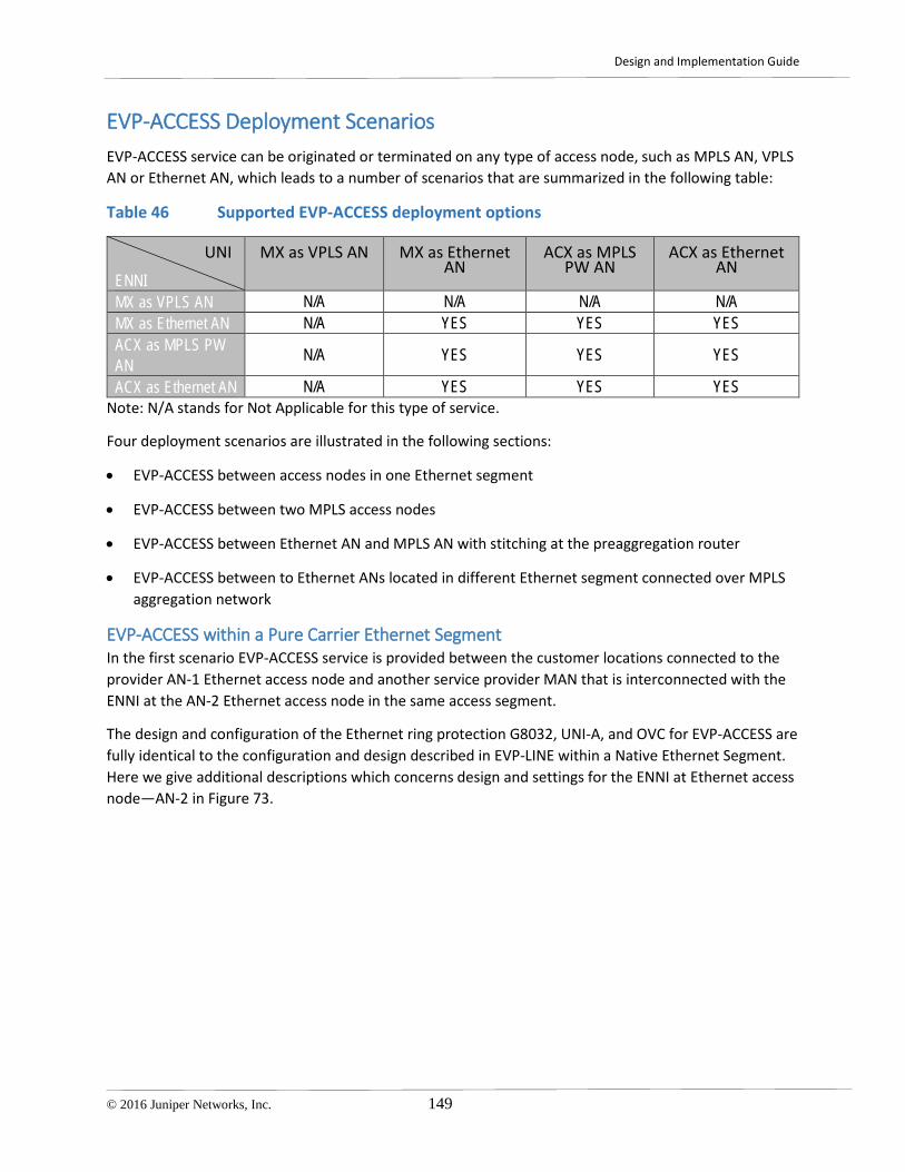
Design and Implementation Guide
© 2016 Juniper Networks, Inc. 149
EVP-ACCESS Deployment Scenarios EVP-ACCESS service can be originated or terminated on any type of access node, such as MPLS AN, VPLS AN or Ethernet AN, which leads to a number of scenarios that are summarized in the following table:
Table 46 Supported EVP-ACCESS deployment options
UNI
ENNI MX as VPLS AN MX as Ethernet
AN ACX as MPLS
PW AN ACX as Ethernet
AN
MX as VPLS AN N/A N/A N/A N/A MX as Ethernet AN N/A YES YES YES ACX as MPLS PW AN N/A YES YES YES
ACX as Ethernet AN N/A YES YES YES Note: N/A stands for Not Applicable for this type of service.
Four deployment scenarios are illustrated in the following sections:
• EVP-ACCESS between access nodes in one Ethernet segment
• EVP-ACCESS between two MPLS access nodes
• EVP-ACCESS between Ethernet AN and MPLS AN with stitching at the preaggregation router
• EVP-ACCESS between to Ethernet ANs located in different Ethernet segment connected over MPLS aggregation network
EVP-ACCESS within a Pure Carrier Ethernet Segment In the first scenario EVP-ACCESS service is provided between the customer locations connected to the provider AN-1 Ethernet access node and another service provider MAN that is interconnected with the ENNI at the AN-2 Ethernet access node in the same access segment.
The design and configuration of the Ethernet ring protection G8032, UNI-A, and OVC for EVP-ACCESS are fully identical to the configuration and design described in EVP-LINE within a Native Ethernet Segment. Here we give additional descriptions which concerns design and settings for the ENNI at Ethernet access node—AN-2 in Figure 73.

Design and Implementation Guide
150 © 2016 Juniper Networks, Inc.
Figure 73 EVP-ACCESS Deployment Scenario for the Ethernet Segment
When customer traffic from AN-1 UNI-A with an S-VLAN tag on top arrives at the ENNI interface of the AN-2 node, the node swaps the S-VLAN tag with a new S-VLAN tag agreed between the two service providers for an operator virtual circuit (OVC). The node also changes the ether-type for the frame to 0x88a8 according to the requirements for the ENNI in MEF 33, and sends traffic through the ENNI—see the solid orange line between AN-2 and service provider 2 MAN cloud. The different color links at the UNI and ENNI in the figure are used to designate the encapsulation types used at each interface. The outer header of the Ethernet frame at the ENNI carries the CoS label, H, M or L, according to the service level agreement. For more details about CoS configuration see CoS Planning for Metro Ethernet Services.
For the traffic from SP-2 MAN to the AN-2 node, the outer tag is swapped back with the S-VLAN tag used in its local MAN for the OVC.
More than one EVP-ACCESS OVC can be mapped to one ENNI, which can be achieved with multiple logical unit configurations at the same ENNI, which correspond to S-VLAN multiplexing attribute (see Table 47).
Table 47 summarizes the EVP-ACCESS service attributes. Assign actual values before using these attributes in the configuration templates for the scenario.
Table 47 EVP-ACCESS Service Attributes for the Ethernet Access Segment
EVC ID OVC YELLOW: <EVC-ID> EVC TYPE EVP-ACCESS
END POINTs AN-1 [ge|xe-<UNI-A>] . <EVC-UNIT-ID>
AN-2 [ge|xe-<UNI-ENNI-B>] . <EVC-UNIT-ID>

Design and Implementation Guide
© 2016 Juniper Networks, Inc. 151
EVC stitching point N/A N/A UNI MTU , byte <MTU-LAN> <MTU-LAN> End Point Segment Ethernet Ethernet END POINT Property <OVC-S-VLAN> EVC VPLS Instance N/A N/A End-Point VPLS Instance N/A N/A S-VLAN <EVC-S-VLAN> <EVC-S-VLAN> End point PW VC ID N/A N/A C-VLAN-ID <C-VLANs> <C-VLANs> C-VLAN-ID Preservation YES YES C-VLAN Bundling YES YES S-VLAN/EVC Multiplexing YES YES COS preservation YES YES BW Profile Per UNI CIR,PIR,CBS,EBS CIR,PIR,CBS,EBS BW Profile Per EVC/OVC CIR,PIR,CBS,EBS CIR,PIR,CBS,EBS
EVP-ACCESS with End-to-End MPLS PW In the second scenario EVP-ACCESS service is provided between the customer location connected to the provider AN-1 MPLS access node and another service provider MAN that is interconnected with ENNI at the AN-2 MPLS access node in the same or different access segment
The design and configuration of the MPLS pseudowire and UNI-A given in EP-LINE with End-to-End MPLS PW are applicable for EVP-ACCESS. Here we give additional descriptions that concerns design and settings for the OVC and ENNI at the AN-2 Ethernet access node in Figure 74 .
Figure 74 EVP-ACCESS Deployment Scenario with End-to-End MPLS PW

Design and Implementation Guide
152 © 2016 Juniper Networks, Inc.
The following actions are taken to forward traffic from UNI-A to ENNI:
1. Customer C-VLAN tagged (802.1q) Ethernet traffic is set from the CPE to the UNI-A provider access node, which is represented by solid red line between the CPE and AN-1.
2. The AN-1 node pushes an additional S-VLAN tag on top of the customer frame and encapsulates frames at the ingress of UNI-A into MPLS pseudowire type 4, encapsulation type vlan-Ethernet, and tunnels the frames over the seamless MPLS access and aggregation network to the AN-2.
3. AN-2 node pops the MPLS service label and swaps the S-VLAN tag with a new S-VLAN tag agreed between the two service providers for the operator virtual circuit (OVC). The node also changes the ether-type for the frame to 0x88a8 according to the requirements for the ENNI given in MEF 33. AN-2 then sends traffic through the ENNI. See the solid orange line between AN-2 and the service provider 2 MAN cloud.
The different color links at the UNI and ENNI in the figure are used to designate the encapsulation type used at each interface.
The outer header of the Ethernet frame at the ENNI carries the CoS label, H, M or L, according to the service level agreement. For more details about CoS configuration see CoS Planning for Metro Ethernet Services.
More than one EP-ACCESS OVC can be mapped to one ENNI, which can be achieved with multiple logical unit configurations at the same ENNI, which correspond to S-VLAN multiplexing attribute (see Table 48).
Table 48 summarizes the EVP-ACCESS service attributes. Assign actual values before using these attributes in the configuration templates for the scenario.
Table 48 EVP-ACCESS Service Attributes for the End-to-End MPLS PW Scenario
EVC ID OVC YELLOW: <EVC-ID> EVC TYPE EVP-ACCESS
END POINTs AN-1 [ge|xe-<UNI-A>] . <EVC-UNIT-ID>
AN-2 [ge|xe-<ENNI-B>] . <EVC-UNIT-ID>
EVC stitching point N/A N/A UNI MTU , byte <MTU-LAN> <MTU-LAN> End Point Segment MPLS MPLS END POINT Property N/A <OVC-S-VLAN> EVC VPLS Instance N/A N/A End-Point VPLS Instance N/A N/A S-VLAN N/A N/A End point PW VC ID <VC-ID-ACTIVE> <VC-ID-ACTIVE> C-VLAN-ID <C-VLANs> <C-VLANs> C-VLAN-ID Preservation YES YES C-VLAN Bundling YES YES S-VLAN/EVC Multiplexing YES YES COS preservation YES YES BW Profile Per UNI CIR,PIR,CBS,EBS CIR,PIR,CBS,EBS BW Profile Per EVC/OVC CIR,PIR,CBS,EBS CIR,PIR,CBS,EBS

Design and Implementation Guide
© 2016 Juniper Networks, Inc. 153
EVP-ACCESS with Ethernet to MPLS PW Stitching In the third scenario EVP-ACCESS service is provided between the customer location connected to the provider AN-1 Ethernet access node and another service provider MAN that is interconnected with the ENNI at the AN-2 MPLS access node in the MPLS access segment.
The design and configuration of the Ethernet ring protection G8032, UNI-A, pseudowires and AG1.1/AG1.2 stitching points are fully identical with the configuration and design described in EVP-LINE with Ethernet to MPLS PW Stitching . Here we give additional descriptions that concern the design and settings for the ENNI at Ethernet access node—AN-2 in Figure 75.
When customer traffic from AN-1 UNI-A with an MPLS service label and S-VLAN tag on top arrives at the ENNI interface of the AN-2 node, the node pops the pseudowire label, swaps the S-VLAN tag with a new S-VLAN tag agreed between the two service providers for the operator virtual circuit (OVC). The node then changes the ether-type for the frame to 0x88a8 according to the requirements for the ENNI in MEF 33 and sends traffic out through the ENNI. See the solid orange line between AN-2 and the service provider 2 MAN cloud. The color of the links at the UNI and ENNI in the figure are used to designate the encapsulation type used at each interface. The outer header of the Ethernet frame at the ENNI carries the CoS label, H, M or L, according to the service level agreement. For more details about the CoS configuration see CoS Planning for Metro Ethernet Services.
For traffic from the SP-2 MAN to AN-2 access node swap back the outer tag with the S-VLAN tag used in its local MAN for the OVC.
Figure 75 EVP-ACCESS Deployment Scenario with Ethernet to PW Stitching

Design and Implementation Guide
154 © 2016 Juniper Networks, Inc.
More than one EVP-ACCESS OVC can be mapped to one ENNI, which can be achieved with multiple logical unit configurations at the same ENNI that correspond to the S-VLAN multiplexing attribute (see Table 49).
Table 49 summarizes the EVP-ACCESS service attributes. Assign actual values before using these attributes in the configuration templates for the scenario.
Table 49 EVP-ACCESS Service Attributes for the Ethernet to MPLS PW Stitching Scenario
EVC ID EVC YELLOW EVC TYPE EP-LAN: <EVC-ID>
END POINTs AN-1 [ge|xe-<UNI-A>]. <EVC-UNIT-ID>
AN-2 [ge|xe-<ENNI-B>] . <EVC-UNIT-ID>
EVC stitching at AGG routers
AG1.1: <ge|xe-AG1.1-NNI-West>. <AG1.1-EVC-UNIT-ID>
AG1.2: <ge|xe-AG1.2-NNI-East>. <AG1.2-EVC-UNIT-ID>
AG2.1 and AG2.2
MTU , byte <MTU-ETH> <MTU-ETH> End Point Segment Ethernet MPLS END POINT Property <OVC-S-VLAN> EVC VPLS Instance CE20-<EVC-ID>-VPLS CE20-<EVC-ID>-VPLS
End-Point VPLS Instance N/A <VC-ID-ACTIVE> <VC-ID-BACKUP>
S-VLAN <EVC-S-VLAN> <EVC-S-VLAN> End point PW VC ID N/A N/A C-VLAN-ID <C-VLANs> <C-VLANs> C-VLAN-ID Preservation YES YES C-VLAN Bundling YES YES S-VLAN/EVC Multiplexing YES YES COS preservation YES YES BW Profile Per UNI CIR,PIR,CBS,EBS CIR,PIR,CBS,EBS
EVP-ACCESS with Ethernet to VPLS Stitching In the fourth scenario EVP-ACCESS service provided between the customer location connected to the provider AN-1 Ethernet access node and another service provider MAN that is interconnected with the ENNI at the AN-2 Ethernet access node in a different access segment.
The design and configuration of the Ethernet ring protection G8032, UNI-A, pseudowires, and service stitching at preaggregation routers are identical to the configuration and design described in EVP-LINE with Carrier Ethernet to VPLS Termination . Here we give additional descriptions that concerns the design and settings for the ENNI at Ethernet access node—AN-2 in Figure 76.

Design and Implementation Guide
© 2016 Juniper Networks, Inc. 155
Figure 76 EVP-ACCESS Deployment Scenario with Ethernet to VPLS Stitching
When customer traffic from AN-1 UNI-A with an MPLS service label and an S-VLAN tag on top arrives at the ENNI interface of the AN-2 node, the node pops the pseudowire label, swaps the S-VLAN tag with a new S-VLAN tag agreed between two the service providers for an operator virtual circuit (OVC). The node then changes the ether-type for the frame to 0x88a8 according to the requirements for the ENNI in MEF 33 and sends traffic to the ENNI. See the solid orange line between AN-2 and the service provider 2 MAN cloud. The different color links at the UNI and ENNI in the figure are used to designate the encapsulation type used at each interface. The outer header of the Ethernet frame at the ENNI carries the CoS label, H, M or L, according to the service level agreement. For details about the CoS configuration see Chapter 9, CoS Planning for Metro Ethernet Services.
For the traffic from SP-2 MAN to the AN-2 access node, swap back the outer tag with the S-VLAN tag used in its local MAN for the OVC.
More than one EVP-ACCESS OVC can be mapped to one ENNI, which can be achieved with multiple logical unit configurations at the same ENNI that correspond to the S-VLAN multiplexing attribute.
Table 50 summarizes the EVP-ACCESS service attributes. Assign actual values before using these attributes in the configuration templates for the scenario.
Table 50 EVP-ACCESS Service Attributes for Ethernet to VPLS Stitching Scenario
EVC ID OVC YELLOW: <EVC-ID> EVC TYPE EVP-ACCESS
END POINTs AN-1 <ge|xe-UNI-A> . <EVC-UNIT-ID>
AN-2 <ge|xe-UNI-B>. <EVC-UNIT-ID>
EVC stitching point AG1.1: AG2.1:

Design and Implementation Guide
156 © 2016 Juniper Networks, Inc.
<ge|xe-AG1.1-NNI-West>. <AG1.1-EVC-UNIT-ID> AG1.2:
<ge|xe-AG1.2-NNI-East>. <AG1.2-EVC-UNIT-ID>
<ge|xe-AG2.1-NNI-West>. <AG2.1-EVC-UNIT-ID> AG2.2:
<ge|xe-AG2.2-NNI-East>. <AG2.2-EVC-UNIT-ID>
UNI MTU , byte <MTU-LAN> <MTU-LAN> End Point Segment Ethernet Ethernet END POINT Property N/A <OVC-S-VLAN> EVC VPLS Instance CE20-<EVC-ID>-VPLS CE20-<EVC-ID>-VPLS End-Point VPLS Instance N/A N/A S-VLAN <EVC-S-VLAN> <EVC-S-VLAN> End point PW VC ID N/A N/A C-VLAN-ID <C-VLANs> <C-VLANs> C-VLAN-ID Preservation YES YES C-VLAN Bundling YES YES S-VLAN/EVC Multiplexing YES YES COS preservation YES YES BW Profile Per UNI CIR,PIR,CBS,EBS CIR,PIR,CBS,EBS BW Profile Per EVC/OVC CIR,PIR,CBS,EBS CIR,PIR,CBS,EBS

Design and Implementation Guide
© 2016 Juniper Networks, Inc. 157
EP-TREE Deployment Scenarios EP-TREE service is represented by the Rooted-Multipoint Ethernet Virtual Connection between the leaf UNIs and the root UNIs. Leaf UNIs can exchange data only with root UNIs, and if any frame from a leaf UNI sends the address associated with another leaf UNI, the frame should be dropped. From a configuration perspective, the EP-TREE configuration is very close to the EP-LAN service configuration. However, the EP-Tree configuration includes additional statements that restrict inter-leaf communication. A true EP-TREE service can be configured only on VPLS enabled access nodes on MX-series routers. You can configure an ACX-series router as a leaf or root UNI, however using ACX-series routers is restricted by customer application or business case.
Table 51 summarizes possible combinations of end points for the EP-Tree Service.
Table 51 Supported EP-Tree Deployment Options
Root UNI
Leaf UNI
MX as VPLS AN MX as Ethernet AN
ACX as MPLS PW AN
ACX as Ethernet AN
MX as VPLS AN YES YES YES,1,2 NO MX as Ethernet AN YES1 YES NO NO ACX as MPLS PW AN YES1,2,3,4 YES4 YES1 2, 3,4 YES 1,2,3,4
ACX as Ethernet AN YES1 YES YES NO
Notes:
1. The EP-Tree root should be located on an MX Series router or on a dedicated aggregation segment with an MX Series router, and VPLS is mandatory.
2. An Aggregation PE router that terminates the PW from root or leaf access node into a VPLS instance cannot have other physical Ethernet ports configured as leaf UNIs in the same VPLS.
3. Some inconsistency may happen in a multi-homing case when the PW from the leaf access node and root access node are terminated on the same pair of AGG routers. Inconsistency leads to traffic leaking from one leaf AN to another. To avoid this situation, one dedicated pair of AG routers should be used to terminate Leaf PW taps, and another dedicated pair of AG routers should be used to terminate root PW taps.
4. As of Junos 12.3S4, ACX Series routers do not support a true VPLS, and should be used as a spoke of the H-VPLS domain. Deployment scenario where multiple UNIs on the same access nodes belong to the same customer has some specific requirements and additional design considerations. See MPLS AN with Multiple UNIs per Customer. .

Design and Implementation Guide
158 © 2016 Juniper Networks, Inc.
EP-TREE with End-to-End VPLS Figure 77 represents the first deployment option for the EP-TREE service provided between four customer locations connected to the provider VPLS access nodes:
• AN-1 VPLS access node interconnects the customer CPE at leaf UNI-A and UNI-C physical ports.
• AN-2 VPLS access node interconnects the customer CPE at leaf UNI-D physical port
• AN-3 VPLS access node, which in a real deployment could be an access node, a core router of the UA&A network, or a provider service edge Layer 2 PE router, interconnects the CPE at root UNI-B physical port.
The design and configuration of the UNIs and EVC for EP-TREE are fully identical to the configuration described in EVP-LAN with MPLS PW to VPLS Termination where all access nodes support the VPLS. No additional service stitching is required in this case. Here we give additional descriptions with regards to settings that provide rooted topology at the service level as shown in Figure 77.
To restrict direct traffic forwarding between leaf UNIs the VPLS routing instance at AN-1 should be configured with the no-local-switching statement, which restricts direct traffic forwarding between local physical UNIs in the same routing instance.
To restrict direct traffic forwarding between leaf UNIs connected to different access nodes, no MPLS pseudowires should be signaled between leaf access nodes AN-1 and AN-2. Depending on what type of protocol—BGP or LDP—used to signal VPLS, different configurations should be used to establish hub and spoke pseudowire topology.
LDP Signaling Restrict the list of available VPLS neighbors in the configuration of the VPLS routing instance at leaf access nodes AN-1 and AN-2 with loopback addresses of the root access nodes only—AN-3 in Figure 77.
BGP Signaling Each leaf access node should be configured with two routing policies, one for import and one for export vrf target community. Policies should be applied to the VPLS routing instance so that only BGP routes with root target community from the root access node—AN-3 in Figure 77—are allowed to be installed into the routing table of the leaf access nodes.

Design and Implementation Guide
© 2016 Juniper Networks, Inc. 159
Figure 77 EP-TREE Deployment Scenario with End-to-End VPLS
Table 52 summarizes the EP-TREE service attributes. Assign actual values before using these attributes in the configuration templates for the scenario.
Table 52 EP-TREE Service Attributes for the End-to-End VPLS PW Scenario
EVC ID EVC BLUE: <EVC-ID> EVC TYPE EP-TREE
END POINTs AN-1 <ge|xe-UNI-A>
AN-2 <ge|xe-UNI-B>
EVC stitching point N/A N/A MTU , byte <MTU-ETH> <MTU-ETH> End Point Segment VPLS VPLS END POINT Property Leaf Root EVC VPLS Instance Attributes CE20-<EVC-ID>-VPLS CE20-<EVC-ID>-VPLS
End-Point VPLS Instance CE20-<EVC-ID>-VPLS CE20-<EVC-ID>-VPLS S-VLAN Optional Optional End point PW VC ID N/A N/A C-VLAN-ID 1-4094 1-4094 C-VLAN-ID Preservation YES YES C-VLAN Bundling YES YES S-VLAN/EVC Multiplexing NO NO COS preservation YES YES BW Profile Per UNI CIR,PIR,CBS,EBS CIR,PIR,CBS,EBS

Design and Implementation Guide
160 © 2016 Juniper Networks, Inc.
BW Profile Per EVC/OVC CIR,PIR,CBS,EBS CIR,PIR,CBS,EBS
EP-TREE with Leaf PW to VPLS Termination Figure 78 represents the second deployment option for the EP-TREE service provided between three customer locations connected to the provider access nodes of different types:
• AN-1 MPLS access node interconnects the customer CPE at the leaf UNI-A physical port.
• AN-2 MPLS access node interconnects the customer CPE at the leaf UNI-C physical port.
• AN-3 VPLS access node, which in real deployment could be either an access node, a core router of the UA&A network, or provider service edge Layer 2 PE router, interconnects the customer CPE at the root UNI-B physical port.
Figure 78 EP-TREE Deployment Scenario with Leaf PW to VPLS Stitching
The design and configuration of the UNIs and EVC for EP-TREE are fully identical to the configuration and design described in EP-LAN with MPLS PW to VPLS Termination. Here we give additional descriptions about the design and configuration settings that provide rooted topology at the service level as shown in Figure 78.
In this scenario each access node originates a pair of active/backup MPLS pseudowires that are terminated into mesh groups within the VPLS routing instances at VPLS hubs—preaggregation routers AG1.1 and AG1.2. Direct traffic forwarding between MPLS pseudowires that are terminated into the same mesh group of the same VPLS routing instance is restricted by default. That assures that no traffic leakage happens between AN-1 and AN-2 if active pseudowires from both access nodes are terminated at the same preaggregation router.

Design and Implementation Guide
© 2016 Juniper Networks, Inc. 161
To restrict direct traffic forwarding between active leaf pseudowires which are terminated into VPLS routing instances at different preaggregation routers additional configuration for the VPLS RI is required. No MPLS pseudowires should be signaled between preaggregation routers which terminates pseudowires from leaf access nodes. Depending on what type of protocol—BGP or LDP—used to signal VPLS different configuration should be used to establish hub and spoke pseudowire topology.
LDP Signaling Restrict the list of available VPLS neighbors in the configuration of the VPLS routing instance at AG1.1 and AG1.2 preaggregation routers with loopback addresses of the root access nodes only—AN-3 in Figure 78.
BGP Signaling Each AG1.1 and AG1.2 preaggregation routers should be configured with two routing policies, one for import and one for export vrf target community. Policies should be applied to the VPLS routing instance so that only BGP routes with root target community from the root access nodes—AN-3 in Figure 78—are allowed to be installed into the routing table of the preaggregation router.
Table 53 summarizes the EP-TREE service attributes. Assign actual values before using these attributes in the configuration templates for the scenario.
Table 53 EP-TREE Service Attributes for the Leaf PW to VPLS Stitching Scenario
EVC ID EVC BLUE: <EVC-ID> EVC TYPE EP-TREE
END POINTs AN-1 <ge|xe-UNI-A>
AN-2 <ge|xe-UNI-B>
EVC stitching point AG2.1 AG2.2 N/A
MTU , byte <MTU-ETH> <MTU-ETH> End Point Segment MPLS PW MPLS VPLS END POINT Property Leaf Root EVC VPLS Instance Attributes CE20-<EVC-ID>-VPLS CE20-<EVC-ID>-VPLS
End-Point VPLS Instance N/A CE20-<EVC-ID>-VPLS S-VLAN Optional Optional
End point PW VC ID <VC-ID-ACTIVE> <VC-ID-BACKUP> N/A
C-VLAN-ID 1-4094 1-4094 C-VLAN-ID Preservation YES YES C-VLAN Bundling YES YES S-VLAN/EVC Multiplexing NO NO COS preservation YES YES BW Profile Per UNI CIR,PIR,CBS,EBS CIR,PIR,CBS,EBS BW Profile Per EVC/OVC CIR,PIR,CBS,EBS CIR,PIR,CBS,EBS

Design and Implementation Guide
162 © 2016 Juniper Networks, Inc.
EP-TREE with Root PW into VPLS Termination Figure 79 represents the third scenario for the EP-TREE service provided between three customer locations connected to the provider VPLS access nodes:
• AN-1 MPLS access node interconnects the customer CPE at leaf UNI-A physical port.
• AN-2 MPLS access node interconnects the customer CPE at leaf UNI-C physical port.
• AN-3 MPLS access node interconnects the customer CPE at root UNI-B physical port.
The design and configuration of the UNIs and EVC for EP-TREE are identical to the configuration and design described in EVP-LAN with MPLS PW to VPLS Termination where all access nodes do not support VPLS. Here we give additional descriptions with regards to design and configuration settings that provide rooted topology at the service level as shown in Figure 79.
Figure 79 EP-TREE Deployment Scenario with Root PW to VPLS Stitching
In this scenario each access node originates pair of active/backup MPLS pseudowires that are terminated into mesh groups within the VPLS routing instances at VPLS hubs—preaggregation routers AG1.1 and AG1.2. Direct traffic forwarding between MPLS pseudowires which are terminated into the same mesh group of the same VPLS routing instance is restricted by default. Doing so assures that no traffic leakage happens between AN-1 and AN-2 if active pseudowires from both access nodes are terminated at the same preaggregation router.
To restrict direct traffic forwarding between active leaf pseudowires that are terminated into VPLS routing instances at different preaggregation routers, additional configuration for the VPLS RI is required. No MPLS pseudowires should be signaled between preaggregation routers that terminate

Design and Implementation Guide
© 2016 Juniper Networks, Inc. 163
pseudowires from leaf access nodes. Depending on what type of protocol, BGP or LDP, used to signal VPLS, different configuration should be used to establish hub and spoke pseudowire topology.
LDP Signaling Restrict the list of available VPLS neighbors in the configuration of the VPLS routing instance at preaggregation routers AG1.1 and AG1.2 with loopback addresses of the preaggregation routers that terminate pseudowires from the AG1.3 and AG1.4 root access nodes in Figure 79.
BGP Signaling Preaggregation routers AG1.1 and AG1.2 should be configured with two routing policies—one for import and one for export of the vrf target community. Policies should be applied to the VPLS routing instance so that only BGP routes with root target community from preaggregation routers that terminates pseudowires from root access nodes AG1.3 and AG1.4 in Figure 79 are allowed to be installed into the routing table of the AG1.1 and AG1.2 routers.
Essential for the design is that different pairs of preaggregation routers are used to terminate pseudowires from the leaf and root access nodes respectively.
Table 54 summarizes the EP-TREE service attributes. Assign actual values before using these attributes in the configuration templates for the scenario.
Table 54 EP-TREE Service Attributes for the Root PW to VPLS Stitching Scenario
EVC ID EVC BLUE: <EVC-ID> EVC TYPE EP-TREE
END POINTs AN-1 <ge|xe-UNI-A>
AN-2 <ge|xe-UNI-B>
EVC stitching point AG1.1 AG1.2
AG2.1 AG2.2
MTU , byte <MTU-ETH> <MTU-ETH> End Point Segment MPLS PW MPLS PW END POINT Property Leaf Root EVC VPLS Instance Attributes CE20-<EVC-ID>-VPLS CE20-<EVC-ID>-VPLS
End-Point VPLS Instance N/A N/A S-VLAN Optional Optional
End point PW VC ID <VC-ID-ACTIVE> <VC-ID-BACKUP>
<VC-ID-ACTIVE> <VC-ID-BACKUP>
C-VLAN-ID 1-4094 1-4094 C-VLAN-ID Preservation YES YES C-VLAN Bundling YES YES S-VLAN/EVC Multiplexing NO NO COS preservation YES YES BW Profile Per UNI CIR,PIR,CBS,EBS CIR,PIR,CBS,EBS BW Profile Per EVC/OVC CIR,PIR,CBS,EBS CIR,PIR,CBS,EBS

Design and Implementation Guide
164 © 2016 Juniper Networks, Inc.
EVP-TREE Deployment Scenarios EVP-TREE service is represented by a Rooted-Multipoint Ethernet Virtual Connection between leaf UNIs and root UNIs. Leaf UNIs can exchange data only with root UNIs. If a frame from a leaf UNI is sent to the address associated with another leaf UNI, the frame should be dropped. From a configuration perspective it is very close to the EVP-LAN service configuration, however it includes some additional commands that restricts inter-leaf communication. A true EVP-TREE service can be configured only on VPLS enabled access nodes on MX-series routers. Depending on circumstances, an ACX Series router can be configured as a leaf or root UNI. Using an ACX Series rout for EVP-TREE is restricted by customer application or business case, and should be deployed with care.
Table 55 summarizes possible combinations of end points for the EVP-Tree Service.
Table 55 Supported EVP-TREE Deployment Options
Root UNI
Leaf UNI
MX as VPLS AN MX as Ethernet AN
ACX as MPLS PW AN
ACX as Ethernet AN
MX as VPLS AN YES YES YES1,2 NO MX as Ethernet AN YES1 YES NO NO ACX as MPLS PW AN YES1,2,3 YES YES1, 2, 3 YES1, 2, 3
ACX as Ethernet AN YES1 YES YES NO
Notes:
1. EVP-TREE root should be located on an MX Series router or on a dedicated aggregation segment with an MX Series router and mandatory VPLS.
5. An aggregation PE router that terminates the PW from the root or leaf access node into the VPLS routing instance cannot have other physical Ethernet ports configured as the leaf UNI in the same VPLS.
6. Some inconsistency may happen in multi-homing cases, when the PW from leaf access node and root access node are terminated on the same pair of AGG routers. Inconsistency leads to traffic leaking from one leaf AN to another. To avoid this situation, one dedicated pair of AG routers should be used to terminate Leaf PW taps, and another dedicated pair of AG routers should be used to terminate root PW taps.
EVP-TREE with End-to-End VPLS Figure 80 represents the first deployment option for the EVP-TREE service provided between four customer locations connected to the provider VPLS access nodes:
• AN-1 VPLS access node interconnects the customer CPE at physical ports—leaf UNI-A and UNI-C.
• AN-2 VPLS access node interconnects the customer CPE at physical port—leaf UNI-D.

Design and Implementation Guide
© 2016 Juniper Networks, Inc. 165
• AN-3 VPLS access node, which in real deployment could be either an access node, a core router of the UA&A network, or a provider service edge Layer 2 PE router, interconnects the customer CPE at the root UNI-B physical port.
The design and configuration of the UNIs and EVC for EVP-TREE are fully identical to the configuration and design described in EVP-LAN with MPLS PW to VPLS Termination where all access nodes support VPLS. No additional service stitching is required. For the design and configuration that provides rooted topology refer to EP-TREE with End-to-End VPLS, which is fully applicable to the scenario in Figure 80.
Figure 80 EVP-TREE Deployment Scenario with End-to-End VPLS
Table 56 summarizes the EVP-TREE service attributes. Assign actual values before using these attributes in the configuration templates for the scenario.
Table 56 EVP-TREE Service Attributes for PW to VPLS Stitching Scenario
EVC ID EVC BLUE: <EVC-ID> EVC TYPE EVP-TREE
END POINTs AN-1 [ge|xe-<UNI-A>] . <EVC-UNIT-ID>
AN-2 [ge|xe-<UNI-B>]. <EVC-UNIT-ID>
EVC stitching point N/A N/A UNI MTU , byte <MTU-LAN> <MTU-LAN> End Point Segment MPLS VPLS MPLS VPLS END POINT Property Leaf Root EVC VPLS Instance CE20-<EVC-ID>-VPLS CE20-<EVC-ID>-VPLS End-Point VPLS Instance CE20-<EVC-ID>-VPLS CE20-<EVC-ID>-VPLS S-VLAN Optional Optional

Design and Implementation Guide
166 © 2016 Juniper Networks, Inc.
End point PW VC ID N/A N/A C-VLAN-ID <C-VLANs> <C-VLANs> C-VLAN-ID Preservation YES YES C-VLAN Bundling YES YES S-VLAN/EVC Multiplexing YES YES COS preservation YES YES BW Profile Per UNI CIR,PIR,CBS,EBS CIR,PIR,CBS,EBS BW Profile Per EVC/OVC CIR,PIR,CBS,EBS CIR,PIR,CBS,EBS
EVP-TREE with Leaf PW to VPLS Termination Figure 81 represents the second deployment option for the EVP-TREE service provided between three customer locations connected to the provider access nodes of different types:
• AN-1 MPLS access node interconnects the customer CPE at physical ports—leaf UNI-A.
• AN-2 MPLS access node interconnects the customer CPE at physical port—leaf UNI-C
• AN-3 VPLS access node, which in real deployment could be an access node, a core router of the UA&A network, or a provider service edge Layer 2 PE router, interconnects the customer CPE at root the UNI-B physical port.
Figure 81 EVP-TREE Deployment Scenario with Leaf PW to VPLS Stitching
The design and configuration of the UNIs, the service stitching points, and EVC for EVP-TREE are identical to the configuration and design described in EVP-LAN with MPLS PW to VPLS Termination. For the design and configuration that provides rooted topology refer to EP-TREE with Leaf PW to VPLS Termination. which is fully applicable to the scenario illustrated in Figure 81.

Design and Implementation Guide
© 2016 Juniper Networks, Inc. 167
Table 57 summarizes the EVP-TREE service attributes. Assign actual values before using these attributes in the configuration templates for the scenario.
Table 57 EVP-TREE Service Attributes for Leaf PW to VPLS Stitching Scenario
EVC ID EVC BLUE: <EVC-ID> EVC TYPE EVP-TREE
END POINTs AN-1 [ge|xe-<UNI-A>] . <EVC-UNIT-ID>
AN-2 [ge|xe-<UNI-B>]. <EVC-UNIT-ID>
EVC stitching point AG2.1 and AG2.2 N/A UNI MTU , byte <MTU-LAN> <MTU-LAN> End Point Segment MPLS PW MPLS VPLS END POINT Property Leaf Root EVC VPLS Instance CE20-<EVC-ID>-VPLS CE20-<EVC-ID>-VPLS End-Point VPLS Instance N/A CE20-<EVC-ID>-VPLS S-VLAN Optional Optional
End point PW VC ID <VC-ID-ACTIVE> <VC-ID-BACKUP> N/A
C-VLAN-ID <C-VLANs> <C-VLANs> C-VLAN-ID Preservation YES YES C-VLAN Bundling YES YES S-VLAN/EVC Multiplexing YES YES COS preservation YES YES BW Profile Per UNI CIR,PIR,CBS,EBS CIR,PIR,CBS,EBS BW Profile Per EVC/OVC CIR,PIR,CBS,EBS CIR,PIR,CBS,EBS

Design and Implementation Guide
168 © 2016 Juniper Networks, Inc.
EVP-TREE with Root PW into VPLS Termination Figure 82 represents the third deployment scenario for the EP-TREE service provided between three customer locations connected to the provider VPLS access nodes:
• AN-1 MPLS access node interconnects the customer CPE at physical ports—leaf UNI-A.
• AN-2 MPLS access node interconnects the customer CPE at physical port—leaf UNI-C
• AN-3 MPLS access node interconnects the customer CPE at physical port—root UNI-B.
Figure 82 EVP-TREE Deployment Scenario with Root and Leaf PWs to VPLS Stitching
The design and configuration of the UNIs, service stitching points and EVC for EVP-TREE are identical to the configuration and design described in EVP-LAN with MPLS PW to VPLS Termination where all access nodes do not support VPLS. For the design and configuration that provides rooted topology, refer to EP-TREE with Root PW into VPLS Termination, which is applicable to the scenario in Figure 82.
Table 58 summarizes the EVP-TREE service attributes. Assign actual values before using these attributes in the configuration templates for the scenario.
Table 58 EP-TREE Service Attributes for Root PW to VPLS Stitching Scenario
EVC ID EVC BLUE: <EVC-ID> EVC TYPE EVP-TREE
END POINTs AN-1 [ge|xe-<UNI-A>] . <EVC-UNIT-ID>
AN-2 [ge|xe-<UNI-B>]. <EVC-UNIT-ID>
EVC stitching point AG1.1 and AG1.2 AG2.1 and AG2.2 UNI MTU , byte <MTU-LAN> <MTU-LAN> End Point Segment MPLS PW MPLS VPLS

Design and Implementation Guide
© 2016 Juniper Networks, Inc. 169
END POINT Property Leaf Root EVC VPLS Instance CE20-<EVC-ID>-VPLS CE20-<EVC-ID>-VPLS End-Point VPLS Instance N/A CE20-<EVC-ID>-VPLS S-VLAN Optional Optional
End point PW VC ID <VC-ID-ACTIVE> <VC-ID-BACKUP>
<VC-ID-ACTIVE> <VC-ID-BACKUP>
C-VLAN-ID <C-VLANs> <C-VLANs> C-VLAN-ID Preservation YES YES C-VLAN Bundling YES YES S-VLAN/EVC Multiplexing YES YES COS preservation YES YES BW Profile Per UNI CIR,PIR,CBS,EBS CIR,PIR,CBS,EBS BW Profile Per EVC/OVC CIR,PIR,CBS,EBS CIR,PIR,CBS,EBS

Design and Implementation Guide
170 © 2016 Juniper Networks, Inc.
S-VLAN Normalization When the EVC for the E-Service spans multiple closed Layer 2 carrier Ethernet segments that are separated by MPLS-enabled metro aggregations and core segments, you may not be able to use the same S-VLAN tag in different segments to map it to the end-to-end EVC (see Figure 83).
Figure 83 S-VLAN Normalization Scenario
In this case a dedicated S-VLAN-tag can be chosen for the EVC. To provide L2 connectivity between the UNIs, S-VLAN normalization should be deployed. The Carrier Ethernet to VPLS stitching point is the point where S-VLAN normalization function logically falls. For multipoint-to-multipoint services such as E-LAN, more than one S-VLAN normalization point may need to be provisioned.
Table 59 summarizes the service attributes for the EVP-LAN that requires S-VLAN normalization.
Table 59 Service attributes for EVC with S-VLAN Normalization
EVC ID EVC GREEN: <EVC-ID> EVC TYPE EVP-LAN
END POINTs AN-1 [ge|xe-<UNI-A>] . <EVC-UNIT-ID>
AN-2 [ge|xe-<UNI-B>]. <EVC-UNIT-ID>
EVC stitching point AG1.1:
<ge|xe-AG1.1-NNI-West>. <AG1.1-EVC-UNIT-ID> AG1.2:
<ge|xe-AG1.2-NNI-East>. <AG1.2-EVC-UNIT-ID>
AG2.1: <ge|xe-AG1.1-NNI-West>. <AG1.1-EVC-UNIT-ID>
AG2.2: <ge|xe-AG1.2-NNI-East>. <AG1.2-EVC-UNIT-ID>
UNI MTU , byte <MTU-LAN> <MTU-LAN> End Point Segment Ethernet MPLS VPLS END POINT Property N/A N/A EVC VPLS Instance CE20-<EVC-ID>-VPLS CE20-<EVC-ID>-VPLS End-Point VPLS Instance N/A CE20-<EVC-ID>-VPLS

Design and Implementation Guide
© 2016 Juniper Networks, Inc. 171
S-VLAN <EVC-S-VLAN-1> <EVC-S-VLAN-NORMAL>
End point PW VC ID <VC-ID-ACTIVE> <VC-ID-BACKUP> N/A
C-VLAN-ID <C-VLANs> <C-VLANs> C-VLAN-ID Preservation YES YES C-VLAN Bundling YES YES S-VLAN/EVC Multiplexing YES YES COS preservation YES YES BW Profile Per UNI CIR,PIR,CBS,EBS CIR,PIR,CBS,EBS BW Profile Per EVC/OVC CIR,PIR,CBS,EBS CIR,PIR,CBS,EBS
Note: <EVC-S-VLAN-NORMAL> will be used as a “normal” tag. S-VLAN-tags from other Layer 2 Ethernet segments should be normalized to its value.

Design and Implementation Guide
172 © 2016 Juniper Networks, Inc.
C-VLAN Translation This topic describes deployment scenarios for the EVP-LINE and EVP-LAN services with customer VLAN tag translation. Figure 84 illustrates C-VLAN translation.
Figure 84 Deployment Scenario for Customer VLAN (C-VLAN) Translation
In the example, EVC 100 provides E-LAN service at three customer locations. Customer CPEs are connected to three access nodes and use three C-VLAN tags, one per location.
AN-1 is configured with native C-VLANs and accepts any type of ingress frames: C-VLAN tagged, untagged, or priority tagged at UNI-A. AN-2 and AN-3 nodes accept only tagged traffic with its own local C-VLAN ID, tags 1200 and 1300 for UNI-B and UNI-C respectively.
Table 60 shows in what combinations of access nodes support C-VLAN translation.
Table 60 Supported Combinations of End-Points and Platforms for C-VLAN Translation
UNI-A UNI-B
MX as MPLS AN MX as Ethernet AN
ACX as MPLS PW AN
ACX as Ethernet AN
MX as MPLS AN YES YES YES YES MX as Ethernet AN YES YES YES YES ACX as MPLS PW AN YES NO1 YES NO1
ACX as Ethernet AN YES YES YES YES Note:

Design and Implementation Guide
© 2016 Juniper Networks, Inc. 173
Deployment scenarios for C-VLAN translation where UNI-A is on an Ethernet node, UNI-B is on MPLS PW nodes, and where the ACX series router is the platform for both access nodes are supported with some restrictions. These scenarios should be considered on case-by-case basis because it may affect the configuration of the service stitching point or for Ethernet ring protection.
UNI-A with native C-VLAN has a regular UNI configuration. Actual C-VLAN translation happens at UNI-B and UNI-C, where local C-VLAN tags are translated to the normal C-VLAN used at UNI-A.
Table 61 summarizes the service attributes for the C-VLAN translation scenarios. For details, see the configuration templates.
Table 61 List of Service Attributes for the C-VLAN Deployment Scenario
EVC ID EVC: <EVC-ID> EVC TYPE EVP-LINE, EVP-LAN, EVP-TREE
END POINTs AN-1 <ge|xe-UNI-A>.<EVC-UNIT-ID>
AN-2 <ge|xe-UNI-B>.<EVC-UNIT-ID>
EVC stitching point Depends on Scenario Depends on Scenario MTU , byte <MTU-LAN> <MTU-LAN> End Point Segment Depends on Scenario Depends on Scenario END POINT Property Native C-VLAN EVC VPLS Instance Attributes Depends on Scenario Depends on Scenario
End-Point VPLS Instance Depends on Scenario Depends on Scenario S-VLAN Depends on Scenario Depends on Scenario End point PW VC ID Depends on Scenario Depends on Scenario C-VLAN-ID <NATIVE-C-VLAN> <LOCAL-C-VLAN> C-VLAN-ID Preservation NO NO C-VLAN Bundling NO NO EVC/S-VLAN Multiplexing YES YES COS preservation NO NO BW Profile Per UNI CIR,PIR,CBS,EBS CIR,PIR,CBS,EBS BW Profile Per EVC/OVC CIR,PIR,CBS,EBS CIR,PIR,CBS,EBS