Embed Size (px)
Citation preview
- 1 -
California Test 111 STATE OF CALIFORNIA—BUSINESS, TRANSPORTATION AND HOUSING AGENCY November 2005
DEPARTMENT OF TRANSPORTATION DIVISION OF ENGINEERING SERVICES Transportation Laboratory 5900 Folsom Blvd. Sacramento, California 95819-4612
METHOD OF DEVELOPING DENSITY AND MOISTURE CALIBRATION TABLES FOR THE NUCLEAR GAGE
CAUTION: Prior to handling test materials, performing equipment setups, and/or conducting
this method, testers are required to read “SAFETY AND HEALTH” in Part 4 of this method. It is the responsibility of the user of this method to consult and use departmental safety and health practices and determine the applicability of regulatory limitations before any testing is performed.
OVERVIEW This is a procedure for developing density
and moisture calibration tables for nuclear gages. Nuclear gage density calibration shall be performed at least once every 15 months with gage radiation count readings taken on a set of three standard density blocks.
A set of three standard density blocks is defined as the three metal density blocks located at the Transportation Laboratory in Sacramento, California (Translab) or any other three metal blocks for which the equivalent densities are established based on the measurements taken on the three metal standard blocks at Translab and verified by the Engineer at Translab. The equivalent densities for any set of three standard density blocks shall be verified at least once every 10 years by the Engineer at Translab following the procedure described in Appendix A. The equivalent densities for the three metal standard density blocks located at Translab shall be verified at least once every 10 years by the Engineer at Translab following a similar procedure to that given in Appendix A using the six California Transportation Laboratory Master Standard Density Blocks that are made of siliceous and calcareous materials. The material densities for the six master density blocks shall be established by weighing and measuring within 30 days prior to their use.
Nuclear gage moisture calibration shall
be performed at least once every 15 months by relating gage count ratios to a set of two moisture standard blocks. A set of two moisture standard blocks is defined as the two moisture standard blocks located at Translab in Sacramento, or the two moisture standard blocks located in the Caltrans districts, or any two Engineer-approved moisture standard blocks owned by a private company. The moisture content of the standard blocks shall be reviewed at least once every 15 months by the Engineer at Translab. Correlation to field moistures may also be developed if this relationship is desired.
Dimensions of standard density/moisture blocks and the edge distance of test holes in standard density blocks shall be of sufficient size to eliminate boundary effect on radioactive counts. For standard density blocks, a minimum height of 10 in for the backscatter detection mode and 2 in deeper than the deepest test depth for the direct penetration mode shall be required. Minimum surface dimensions of 24 in long by 17 in wide may be adequate for standard density blocks if the test hole is placed such that the boundary effect is minimized. A minimum 4 in may be an appropriate value for the edge distance of test holes in density blocks.

California Test 111 November 2005
- 2 -
Three metal standard blocks may be made of aluminum, magnesium, a combination of these, or other metal materials from which the calibration curve/table can be used to interpolate accurate densities for materials to be tested. To express the standard count limits within which the calibration of a gage is valid, the acceptable deviation limit (ADL) is defined in this test method as ADL = 0.03n where n = standard count at calibration of the gage. The strength of radioactive sources in gages decays naturally with time. The natural decay ratio in percentage for typical radioactive sources used in nuclear gages is provided in Table 1. Any subsequent standard count shall be within ± ADL of the standard count value used for the calibration after the natural source decay is taken into account. If it is not, a new ADL and calibration table shall be established after the gage is checked and repaired if necessary.
This method is divided into the following
parts: 1. Principle of the Method
2. Procedure for Density Calibration
3. Procedure for Moisture Calibration
4. Safety and Health
Appendix A. Procedure for determining the equivalent densities of three metal blocks to be used as standard blocks.
PART 1. PRINCIPLE OF THE METHOD A. DENSITY CALIBRATION
A set of three metal standard density blocks is utilized to perform a nuclear gage density calibration. Radioactive count readings on each of the three standard blocks shall be taken at a specific test mode of a gage to be calibrated after standard counts are read. The test mode is in terms of penetration depth of the gage source rod. The test modes include the backscatter
detection mode, and 2 in, 3 in, 4 in, 5 in, 6 in, 7 in, and 8 in penetration depths. A nuclear gage may also be calibrated at 10 in and 12 in penetration depths or Asphalt/Concrete (A/C) mode. The linear regression analysis expressed below is implemented on the data samples for each of the test modes of a gage.
y = d0 + d1x
In which y represents the density of the material considered and x = ln (CR) – the natural logarithm function of CR, where CR is the count ratio of measured count to standard count. The coefficients d0 and d1 are to be determined by the least-square method. The quality of calibration data can be evaluated using the correlation coefficient or the standard error of the regression line.
B. MOISTURE CALIBRATION
A set of two moisture standard blocks is used in the procedure for moisture calibration. Radioactive count readings are taken on the two blocks at the moisture test mode of a gage to be calibrated after standard counts are read. A straight line is drawn on normal linear scale and a calibration table is generated. The mathematical equation for nuclear gage moisture calibration may be expressed as
y = m0 + m1x
in which y stands for the moisture of the material considered and x = CR, where CR is the count ratio of measured count to standard count. The coefficients m0 and m1 are to be determined by calibration measurements taken on two moisture standard blocks.
PART 2. PROCEDURE FOR DENSITY
CALIBRATION A. APPARATUS
1. The nuclear gage to be calibrated and the manufacturer’s standard block.
2. A set of three metal standard density
blocks.
California Test 111 November 2005
- 3 -
B. STANDARD COUNT
1. Set the manufacturer’s standard block 5 feet from any object and 25 feet from any gage or radioactive source to eliminate radioactive interference.
2. Place the gage on the standard block
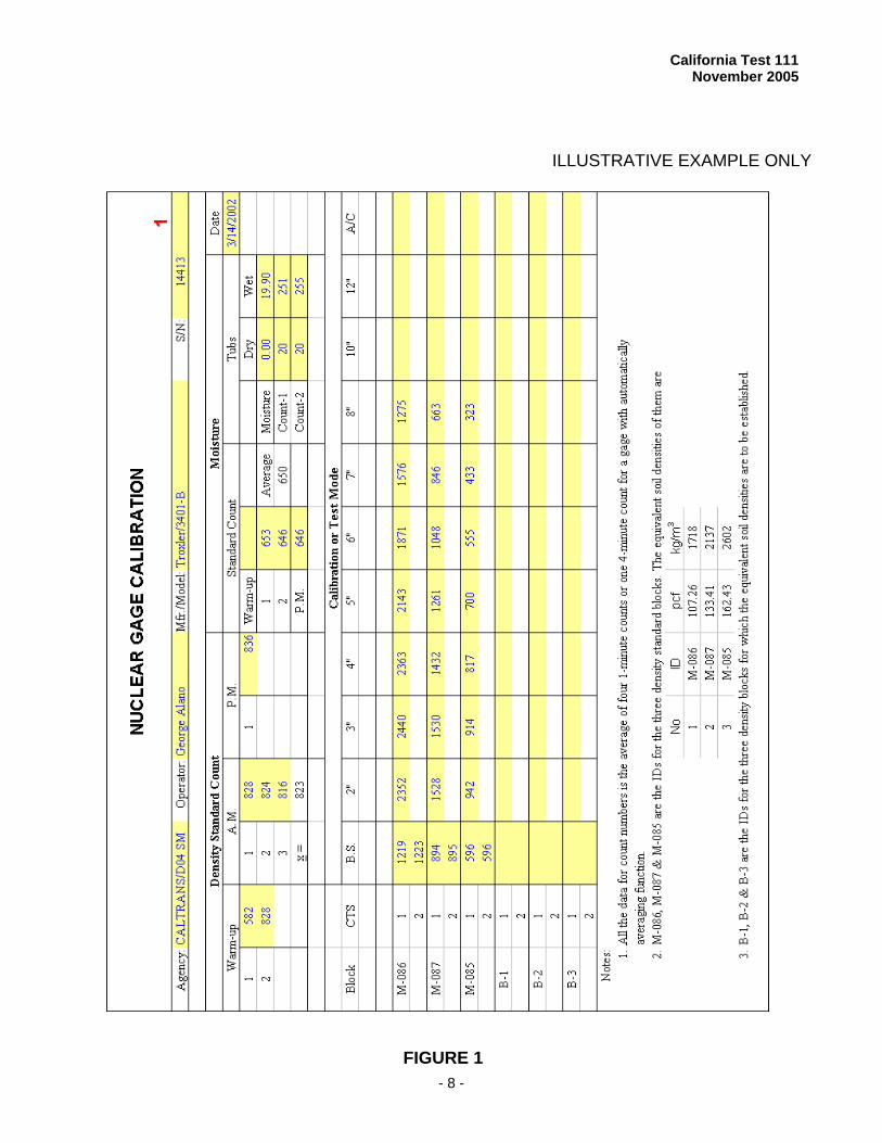
in the safe position and take eight 1-minute density counts. The eight measurements taken are part of the warm-up procedure and are entered in a gage logbook, but are not used in the subsequent parts of this procedure. After the warm-up, take twelve 1-minute counts for density. Record the average of each set of four consecutive 1-minute counts under the label "A.M." on the form shown in Figure 1 and in the gage logbook. The average of the twelve measurements is the standard count for the gage.
If the nuclear gage is equipped with
electronic circuitry capable of automatically averaging four 1-minute density counts, four consecutive 1-minute density counts can be taken as one 4-minute count equivalently and Step 2 can be performed slightly differently. Place the gage on the standard block in the safe position and take two 4-minute (warm-up) counts and record the data in the gage logbook. After the warm-up, take three 4-minute counts for density. Record each 4-minute count on the form shown in Figure 1 and in the gage logbook. The data of gage counts on the form is the average of four 1-minute count readings or one 4-minute count for a gage with automatically averaging function.
C. COUNT READINGS ON THREE STANDARD
DENSITY BLOCKS
1. Set the gage source rod at the desired depth and position the gage on one of the three metal standard blocks with the rod in the hole provided for this detection. The gage is placed so that the rod is firmly against the side of the hole nearest to the gage. All
blocks must be placed at least 25 feet apart and 25 feet from any gage or radioactive source to eliminate radioactive interference unless there is proper shielding between the blocks.
2. Take four 1-minute counts at a test
mode. A test mode is referred to as the backscatter detection mode, A/C mode, or one of the following nominal penetration depths: 2 in, 3 in, 4 in, 5 in, 6 in, 7 in, and 8 in, 10 in and 12 in penetration depths. For a gage with averaging function, four consecutive 1-minute density counts can be taken as one 4-minute count equivalently. Record all data on the form shown in Figure 1. For the backscatter detection mode, additional four 1-minute counts or one 4-minute count is required due to high variation in count readings at this position.
Nominal direct transmission depth
defines the approximate depth at which the rod is placed. The direct transmission depth is the nominal direct transmission depth ± 0.1 inch and is defined as the actual penetration depth setting at which the soil density gage rod is manufactured to stop.
3. Repeat Steps 1 to 2 above on the
other two metal standard blocks and record all data on the form shown in Figure 1.
4. Take post-test standard count
readings to check gage stability and record the data under the label "P.M." on the form as shown in Figure 1.
D. PRESENTATION OF CALIBRATION DATA
1. Present the calibration data from the three metal standard blocks for a gage at all test modes on a semi-log scale plot as shown in Figure 3.
2. Determine the "best fitting" straight
line using the "Least-Square" method for each of the test modes considered. Present the correlation coefficient of
California Test 111 November 2005
- 4 -
the regression on the plot as shown in Figure 3. If the correlation coefficient for a test mode is less than 0.999 or the standard error of the linear regression is greater than 1 lb/ft3, the gage at this test mode shall be re-calibrated.
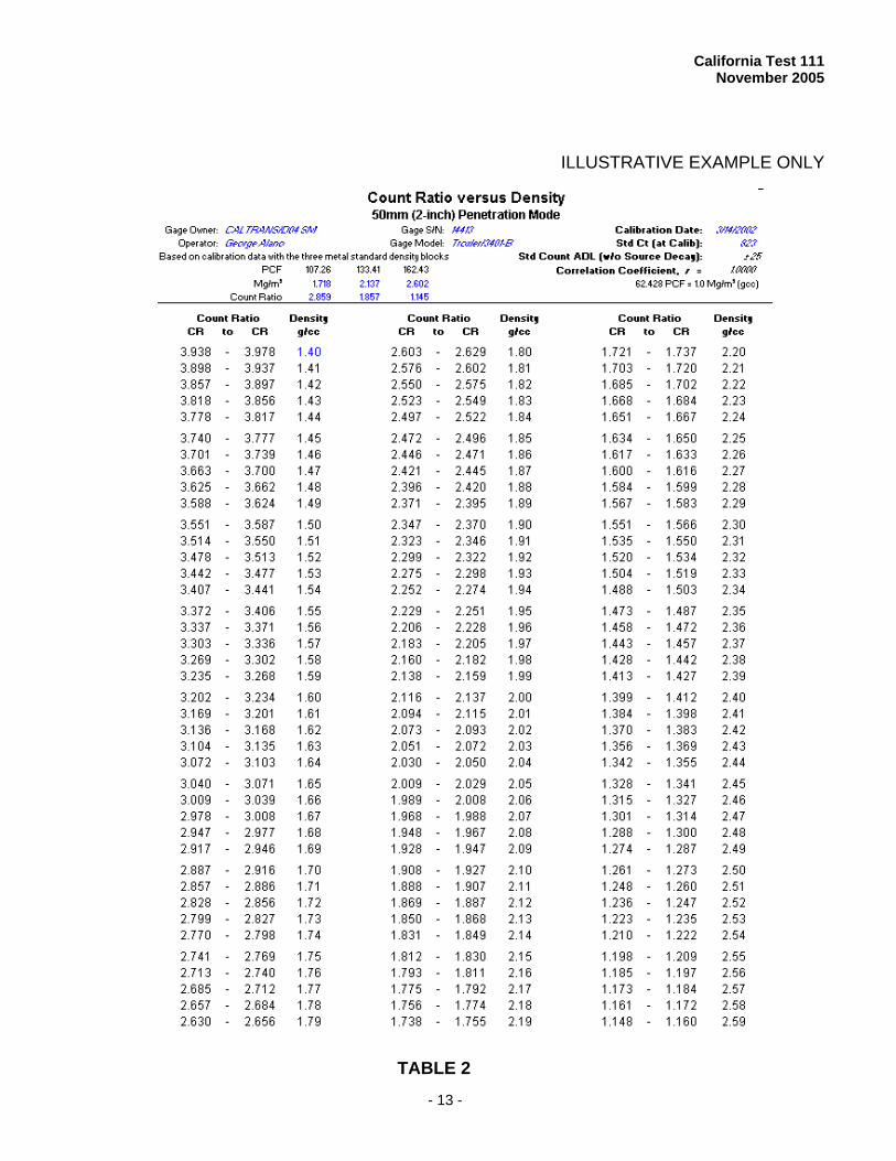
3. Generate calibration tables as
depicted in Table 2, one table for each calibrated test mode. Present basic information of the calibration on the table, including: 3.1 Gage Owner 3.2 Operator 3.3 Gage serial number 3.4 Gage manufacturer and model 3.5 Calibration date 3.6 Calibration data points 3.7 Standard count and its limits
beyond which the calibration table cannot be applied
PART 3. PROCEDURE FOR MOISTURE
CALIBRATION A. APPARATUS
1. The nuclear gage to be calibrated and
the manufacturer’s standard block.
2. A set of two moisture standards. B. CALIBRATION PROCEDURE
1. Take standard counts by following the
procedure in Part 2, Section B, except take moisture readings instead of density readings. Record the data under the label "Moisture." on the form shown in Figure 1. One warm-up, one post-test and two pre-test standard counts for moisture can be recorded in the space provided for the moisture standard counts. The warm-up may not be necessary if the density counts were already made during the same day.
2. Place the gage on the first moisture standard block at the moisture test mode of a gage and take four 1-minute counts or one 4-minute count for a gage with automatically averaging function. Record the first
data on the form shown in Figure 1. Lift the gage and re-place it on the same standard block for a second data. Average the two numbers to obtain the mean count for this standard block.
3. Repeat Step 2 on the second moisture
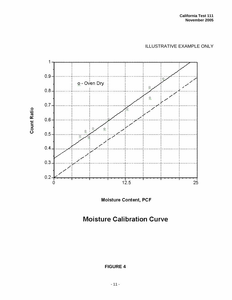
standard block. 4. Present the two data points on a
normal linear scale plot and connect the points using a straight line, as shown in Figure 4. Calculate the intercept and slope of the straight line and determine the calibration equation.
5. Tabulate the moisture calibration as shown in Table 3. Present basic information of the calibration on the table, including:
5.1 Gage Owner 5.2 Operator 5.3 Gage serial number 5.4 Gage manufacturer and model 5.5 Calibration date 5.6 Calibration data points 5.7 Standard count and its limits
beyond which the calibration table cannot be applied
The calibration on the two standard blocks may not give moisture content comparable to oven drying (California Test 226). If the correlation between gage calibration moistures and oven-dry moistures is needed, the calibration moisture must be verified by performing nuclear gage field moisture tests and relating test results to oven-dry moistures and field densities.
C. FIELD MOISTURE CALIBRATION PROCEDURE 1. Follow the procedure described in
Part 3, Sections A, B-1, B-2, B-3 and B-4 to obtain the standard calibration data for a gage to be checked.
2. Plot the data from Step 1 and draw a
straight line (the dashed line in Figure 4).
California Test 111 November 2005
- 5 -
3. Take at least 10 nuclear gage field moisture and density tests (California Test 231).
4. At these same sites, take
representative soil samples and determine oven-dry moistures (California Test 226).
5. Plot the gage field count ratios versus
field moistures (Figure 4). 6. Draw a best fitting straight line
through the field data points and parallel to the standard calibration line determined in Step 2.
7. Take count ratios of 0.5 and 0.8 and
the corresponding moistures at these two points. Use the two data points to obtain the field moisture calibration table.
PART 4. SAFETY AND HEALTH
All rules and regulations in the operators manual and the State of California Administration Code, Title 17, of the State of California, Department of Health Services shall be followed.
Prior to handling, testing or disposing of any waste materials, testers are required to read: Part A (Section 5.0), Part B (Section: 5.0, 6.0 and 10.0) and Part C (Section 2.0) of Caltrans Laboratory Safety Manual. Users of this method do so at their own risk.
REFERENCES California Tests 121, 226 and 231
End of Text
(California Test 111 contains 14 pages)
California Test 111 November 2005
- 6 -
APPENDIX A
PROCEDURE FOR DETERMINING THE EQUIVALENT DENSITIES OF THREE METAL BLOCKS A. APPARATUS
1. A group of at least 20 nuclear gages and their companion manufacturer’s standard blocks
2. The three metal standard density
blocks located at Translab in Sacramento
3. A set of three metal blocks for which
the equivalent densities are to be established
B. STANDARD COUNT
1. Start with one gage in the group of
at least 20 gages. Set the manufacturer’s standard block 5 feet from any object and 25 feet from any gage or radioactive source to eliminate radioactive interference.
2. Place the gage on the standard block
in the safe position and take eight 1-minute density counts. The eight measurements taken are part of the warm-up procedure and are entered in a gage logbook, but are not used in the subsequent parts of this procedure. After the warm-up, take twelve 1-minute counts for density. Record the average of each set of four consecutive 1-minute counts under the label "A.M." on the form shown in Figure 1 and in the gage logbook. The average of the twelve measurements is the standard count for the gage.
If the nuclear gage is equipped with
electronic circuitry capable of automatically averaging four 1-minute density counts, four consecutive 1-minute density counts can be taken as one 4-minute count equivalently and Step 2 can be performed slightly differently. Place the gage on the standard block in the safe position and take two 4-minute (warm-up) counts and record the data in the gage logbook. After the warm-
up, take three 4-minute counts for density. Record each 4-minute count on the form shown in Figure 2 and in the gage logbook. The data of gage counts on the form is the average of four 1-minute count readings or one 4-minute count for a gage with automatically averaging function.
C. COUNT READINGS ON TWO SETS OF
DENSITY BLOCKS
1. Set the gage source rod at the desired depth and position the gage on one of the three metal standard blocks with the rod in the hole provided for this detection. The gage is placed so that the rod is firmly against the side of the hole nearest to the gage. All blocks must be placed at least 25 feet apart and 25 feet from any gage or radioactive source unless there is proper shielding between the blocks.
2. Take four 1-minute counts at a test
mode. A test mode is referred to as the backscatter detection mode, A/C mode, or one of the following nominal penetration depths: 2 in, 3 in, 4 in, 5 in, 6 in, 7 in, and 8 in, 10 in and 12 in. For a gage with averaging function, four consecutive 1-minute density counts can be taken as one 4-minute count equivalently. Record all data on the form shown in Figure 2. For the backscatter detection mode, additional four 1-minute counts or one 4-minute count is required due to high variation in count readings at this position.
Nominal direct transmission depth
defines the approximate depth at which the rod is placed. The direct transmission depth is the nominal direct transmission depth ± 0.1 inch and is defined as the actual penetration depth setting at which the soil density gage rod is manufactured to stop.
California Test 111 November 2005
- 7 -
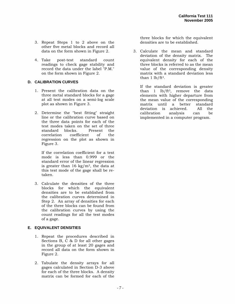
3. Repeat Steps 1 to 2 above on the
other five metal blocks and record all data on the form shown in Figure 2.
4. Take post-test standard count
readings to check gage stability and record the data under the label "P.M." on the form shown in Figure 2.
D. CALIBRATION CURVES
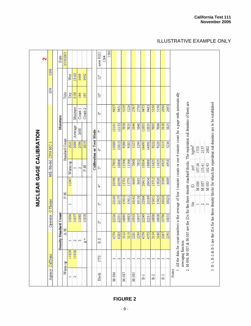
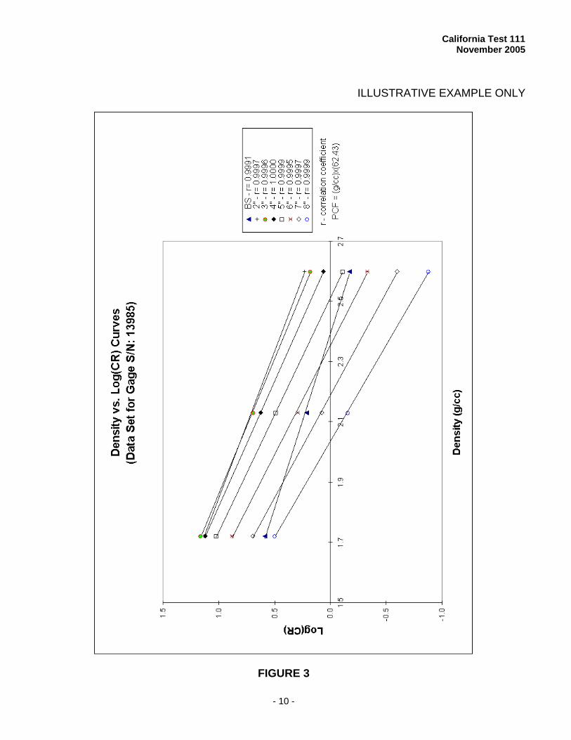
1. Present the calibration data on the three metal standard blocks for a gage at all test modes on a semi-log scale plot as shown in Figure 3.
2. Determine the "best fitting" straight
line or the calibration curve based on the three data points for each of the test modes taken on the set of three standard blocks. Present the correlation coefficient of the regression on the plot as shown in Figure 3.
If the correlation coefficient for a test mode is less than 0.999 or the standard error of the linear regression is greater than 16 kg/m3, the data at this test mode of the gage shall be re-taken.
3. Calculate the densities of the three
blocks for which the equivalent densities are to be established from the calibration curves determined in Step 2. An array of densities for each of the three blocks can be found from the calibration curves by using the count readings for all the test modes of a gage.
E. EQUIVALENT DENSITIES
1. Repeat the procedures described in
Sections B, C & D for all other gages in the group of at least 20 gages and record all data on the form shown in Figure 2.
2. Tabulate the density arrays for all
gages calculated in Section D-3 above for each of the three blocks. A density matrix can be formed for each of the
three blocks for which the equivalent densities are to be established.
3. Calculate the mean and standard
deviation of the density matrix. The equivalent density for each of the three blocks is referred to as the mean value of the corresponding density matrix with a standard deviation less than 1 lb/ft3.
If the standard deviation is greater than 1 lb/ft3, remove the data elements with higher departure from the mean value of the corresponding matrix until a better standard deviation is achieved. All the calibration analysis can be implemented in a computer program.
California Test 111 November 2005
- 8 -
ILLUSTRATIVE EXAMPLE ONLY
FIGURE 1
California Test 111 November 2005
- 9 -
ILLUSTRATIVE EXAMPLE ONLY
FIGURE 2
California Test 111 November 2005
- 10 -
ILLUSTRATIVE EXAMPLE ONLY
FIGURE 3
California Test 111 November 2005
- 11 -
ILLUSTRATIVE EXAMPLE ONLY
FIGURE 4
California Test 111 November 2005
- 12 -
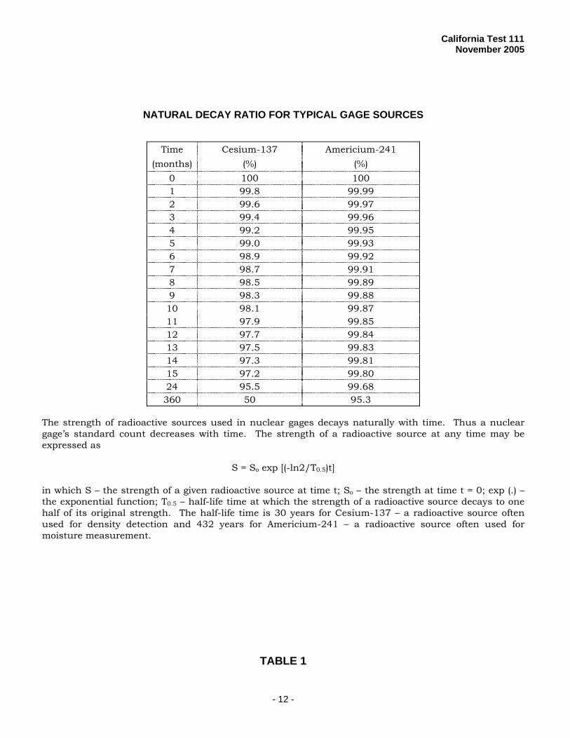
NATURAL DECAY RATIO FOR TYPICAL GAGE SOURCES
Time (months)
Cesium-137 (%)
Americium-241 (%)
0 100 100 1 99.8 99.99 2 99.6 99.97 3 99.4 99.96 4 99.2 99.95 5 99.0 99.93 6 98.9 99.92 7 98.7 99.91 8 98.5 99.89 9 98.3 99.88 10 98.1 99.87 11 97.9 99.85 12 97.7 99.84 13 97.5 99.83 14 97.3 99.81 15 97.2 99.80 24 95.5 99.68 360 50 95.3
The strength of radioactive sources used in nuclear gages decays naturally with time. Thus a nuclear gage’s standard count decreases with time. The strength of a radioactive source at any time may be expressed as
S = So exp [(-ln2/T0.5)t] in which S – the strength of a given radioactive source at time t; So – the strength at time t = 0; exp (.) – the exponential function; T0.5 – half-life time at which the strength of a radioactive source decays to one half of its original strength. The half-life time is 30 years for Cesium-137 – a radioactive source often used for density detection and 432 years for Americium-241 – a radioactive source often used for moisture measurement.
TABLE 1
California Test 111 November 2005
- 13 -
ILLUSTRATIVE EXAMPLE ONLY
TABLE 2

California Test 111 November 2005
- 14 -
ILLUSTRATIVE EXAMPLE ONLY
COUNT RATIO VS. MOISTURE FOR NUCLEAR GAGE NO. 5050
CR To CR
kg/m3
CR To CR
kg/m3
CR To CR
kg/m3
0.069 - 0.092 00 0.532 - 0.554 200 0.995 - 1.017 400 0.093 - 0.115 10 0.555 - 0.578 210 1.018 - 1.041 410 0.116 - 0.138 20 0.579 - 0.601 220 1.042 - 1.061 420 0.139 - 0.161 30 0.302 - 0.324 230 1.065 - 1.087 430 0.162 - 0.184 40 0.625 - 0.647 240 1.088 - 1.110 440
0.185 - 0.207 50 0.648 - 0.670 250 1.111 - 1.133 450 0.208 - 0.230 60 0.671 - 0.693 260 1.134 - 1.156 460 0.231 - 0.254 70 0.694 - 0.717 270 1.157 - 1.179 470 0.255 - 0.277 80 0.718 - 0.740 280 1.180 - 1.203 480 0.278 - 0.300 90 0.741 - 0.763 290 1.204 - 1.226 490
0.301 - 0.323 100 0.764 - 0.786 300 1.227 - 1.249 500 0.324 - 0.346 110 0.787 - 0.809 310 1.250 - 1.272 510 0.347 - 0.369 120 0.810 - 0.832 320 1.273 - 1.295 520 0.370 - 0.392 130 0.833 - 0.855 330 1.296 - 1.318 530 0.393 - 0.416 140 0.856 - 0.879 340 1.319 - 1.341 540
0.417 - 0.439 150 0.880 - 0.902 350 1.342 - 1.365 550 0.440 - 0.462 160 0.903 - 0.925 360 1.366 - 1.388 560 0.463 - 0.485 170 0.926 - 0.948 370 1.389 - 1.411 570 0.486 - 0.508 180 0.949 - 0.971 380 1.412 - 1.434 580 0.509 - 0.531 190 0.972 - 0.994 390 1.435 - 1.457 590
TABLE 3
Count Ratio versus Moisture
Gage Owner: Caltrans - D06 Gage S/N: 5050 Calibration Date: 5/10/96Operator: F. Champion Gage Model: Std Ct (at Calib): 5560
Based on calibration data with the two state standard moisture blocks Std Count ADL: ± 167PCF 0.00 18.79 1000 kg/m3 = 62.428 PCF
kg/m3 0.0 301.0Count Ratio 0.080 0.777