Embed Size (px)
Citation preview

Meridian 1
Meridian BRAnch VOice 1.0Description, Installation, and Operation
Document Number: 553-3001-203Document Release: Standard 2.00Date: April 2000
Year Publish FCC TM
Copyright © 1999–2000 Nortel NetworksAll Rights Reserved
Printed in Canada
Information is subject to change without notice. Nortel Networks reserves the right to make changes in design or components as progress in engineering and manufacturing may warrant. This equipment has been tested and found to comply with the limits for a Class A digital device pursuant to Part 15 of the FCC rules, and the radio interference regulations of Industry Canada. These limits are designed to provide reasonable protection against harmful interference when the equipment is operated in a commercial environment. This equipment generates, uses and can radiate radio frequency energy, and if not installed and used in accordance with the instruction manual, may cause harmful interference to radio communications. Operation of this equipment in a residential area is likely to cause harmful interference in which case the user will be required to correct the interference at their own expense.
SL-1 and Meridian 1 are trademarks of Nortel Networks.
Meridian BRAnch VOice 1.0 Description, Installation, and Operation


Page 3 of 172
4
se
Revision historyApril 2000
Standard 2.00. This is a global document and is up-issued for X11 Relea25.0x.
October 1999Standard 1.00.
Meridian BRAnch VOice 1.0 Description, Installation, and Operation

Page 4 of 172 Revision History
553-3001-203 Standard 2.00 April 2000
Page 5 of 172
8
9
10
151617
2323
24
27
282931
333436
37
39394243
Contents
About this document . . . . . . . . . . . . . . . . . . . . . . . 9Description of Chapters . . . . . . . . . . . . . . . . . . . . . . . . . . . . . . . . . . . .
Related NTPs . . . . . . . . . . . . . . . . . . . . . . . . . . . . . . . . . . . . . . . . . . . .
Description . . . . . . . . . . . . . . . . . . . . . . . . . . . . . . . . 15Product overview . . . . . . . . . . . . . . . . . . . . . . . . . . . . . . . . . . . . . . . . .
BRAnch VOice support for the MCDN feature set . . . . . . . . . . . . BRAnch VOice dialing plan overview . . . . . . . . . . . . . . . . . . . . . . Multiple-card branches . . . . . . . . . . . . . . . . . . . . . . . . . . . . . . . . . . BRAnch VOice branch ID and card ID . . . . . . . . . . . . . . . . . . . . .
BRAnch VOice functional description . . . . . . . . . . . . . . . . . . . . . . . .
Feature set summary for BRAnch VOice . . . . . . . . . . . . . . . . . . . . . .
ISDN serial link (ISL) overview . . . . . . . . . . . . . . . . . . . . . . . . . . . . . BRAnch VOice call setup . . . . . . . . . . . . . . . . . . . . . . . . . . . . . . . BRAnch VOice fallback to alternative routes . . . . . . . . . . . . . . . . .
BRAnch VOice card physical description . . . . . . . . . . . . . . . . . . . . . PCMCIA cards . . . . . . . . . . . . . . . . . . . . . . . . . . . . . . . . . . . . . . . . Supported interfaces . . . . . . . . . . . . . . . . . . . . . . . . . . . . . . . . . . . .
Engineering guidelines . . . . . . . . . . . . . . . . . . . . . . 37X11 system software requirements . . . . . . . . . . . . . . . . . . . . . . . . . . .
Hardware requirements . . . . . . . . . . . . . . . . . . . . . . . . . . . . . . . . . . . . Meridian 1 hardware requirements . . . . . . . . . . . . . . . . . . . . . . . . . BRAnch VOice hardware requirements . . . . . . . . . . . . . . . . . . . . . External equipment requirements . . . . . . . . . . . . . . . . . . . . . . . . . .
Meridian BRAnch VOice 1.0 Description, Installation, and Operation
Page 6 of 172 Contents
43434445
474751
58
59
61
62
6363
6363
66
68
696969
70
70
7474757678794
87
BRAnch VOice networking configurations . . . . . . . . . . . . . . . . . . . . . Branch/HQ node . . . . . . . . . . . . . . . . . . . . . . . . . . . . . . . . . . . . . . . Branch/HQ cluster . . . . . . . . . . . . . . . . . . . . . . . . . . . . . . . . . . . . . . MCDN network extension . . . . . . . . . . . . . . . . . . . . . . . . . . . . . . .
BRAnch VOice networking guidelines . . . . . . . . . . . . . . . . . . . . . . . . BRAnch VOice branch ID and card ID . . . . . . . . . . . . . . . . . . . . . Engineer BRAnch VOice cards . . . . . . . . . . . . . . . . . . . . . . . . . . . Minimize multiple call hops . . . . . . . . . . . . . . . . . . . . . . . . . . . . . .
Operational Measurements . . . . . . . . . . . . . . . . . . . . . . . . . . . . . . . . .
Installation and configuration . . . . . . . . . . . . . . . . 61Before you begin . . . . . . . . . . . . . . . . . . . . . . . . . . . . . . . . . . . . . . . . .
Installation summary . . . . . . . . . . . . . . . . . . . . . . . . . . . . . . . . . . . . . .
Installation preparation . . . . . . . . . . . . . . . . . . . . . . . . . . . . . . . . . . . . Inspect the package contents . . . . . . . . . . . . . . . . . . . . . . . . . . . . . . Take inventory . . . . . . . . . . . . . . . . . . . . . . . . . . . . . . . . . . . . . . . . Choose the card slot . . . . . . . . . . . . . . . . . . . . . . . . . . . . . . . . . . . . Install and connect the D-channel PCMCIA interface card . . . . . .
BRAnch VOice card installation . . . . . . . . . . . . . . . . . . . . . . . . . . . . .
BRAnch VOice card cabling . . . . . . . . . . . . . . . . . . . . . . . . . . . . . . . . Connect the I/O panel cable . . . . . . . . . . . . . . . . . . . . . . . . . . . . . . Connect the serial maintenance port (P2) to a terminal . . . . . . . . . Connect the LAN port (P3) to the management LAN . . . . . . . . . . Connect the D-channel interface port (P4) to the MSDL or SDI/DCH card . . . . . . . . . . . . . . . . . . . . . . . . . . . . . . . .
X11 system configuration . . . . . . . . . . . . . . . . . . . . . . . . . . . . . . . . . . Overlay 15 . . . . . . . . . . . . . . . . . . . . . . . . . . . . . . . . . . . . . . . . . . . . Configure D-channels in Overlay 17 . . . . . . . . . . . . . . . . . . . . . . . Configure trunk routes in Overlay 16 . . . . . . . . . . . . . . . . . . . . . . . Configure trunks in Overlay 14 . . . . . . . . . . . . . . . . . . . . . . . . . . . Configure the dialing plan with Overlays 86, 87, and 90 . . . . . . . . Configure Incoming Digit Conversion (IDC) . . . . . . . . . . . . . . . . . 8
Administration through the CLI . . . . . . . . . . . . . . 87Navigation help . . . . . . . . . . . . . . . . . . . . . . . . . . . . . . . . . . . . . . . . . .
553-3001-203 Standard 2.00 April 2000

Contents Page 7 of 172
87
88
8890
971
05
11012131417
12226
132
13739
141
143
144
145
146146147148
150150
151
154
157
Administration tasks summary . . . . . . . . . . . . . . . . . . . . . . . . . . . . . . .
Access the CLI . . . . . . . . . . . . . . . . . . . . . . . . . . . . . . . . . . . . . . . . . . .
BRAnch VOice configuration description . . . . . . . . . . . . . . . . . . . . . . BRAnch VOice Card Parameters configuration . . . . . . . . . . . . . . . BRAnch VOice IP Address configuration . . . . . . . . . . . . . . . . . . . BRAnch VOice SNMP Traps/Alarms Main configuration . . . . . . . 10BRAnch VOice SNMP Traps/Alarms configuration . . . . . . . . . . . 1MAT configuration for receiving SNMP Traps/Alarmsfrom BRAnch VOice . . . . . . . . . . . . . . . . . . . . . . . . . . . . . . . . . . . . BRAnch VOice Dial Plan configuration . . . . . . . . . . . . . . . . . . . . . 1BRAnch VOice Dial Plan overview . . . . . . . . . . . . . . . . . . . . . . . . 1BRAnch VOice Access Codes (AC1 and AC2) configuration . . . . 1BRAnch VOice Location Code configuration . . . . . . . . . . . . . . . . 1BRAnch VOice Distance Steering Codes configuration . . . . . . . . . BRAnch VOice Trunk Steering Codes configuration . . . . . . . . . . . 1BRAnch VOice Software Upgrade . . . . . . . . . . . . . . . . . . . . . . . . .
Configure BRAnch VOice system/card date and time . . . . . . . . . . . . . Configuring a new BRAnch VOice card . . . . . . . . . . . . . . . . . . . . . 1BRAnch VOice shell commands . . . . . . . . . . . . . . . . . . . . . . . . . . .
D-Channel PCMCIA card upgrade . . . . . . . . . . . . . . . . . . . . . . . . . . .
8051XA auxiliary processor upgrade . . . . . . . . . . . . . . . . . . . . . . . . . .
Maintenance . . . . . . . . . . . . . . . . . . . . . . . . . . . . . . . 145Maintenance overview . . . . . . . . . . . . . . . . . . . . . . . . . . . . . . . . . . . . .
BRAnch VOice diagnostic tools . . . . . . . . . . . . . . . . . . . . . . . . . . . . . LED indicators . . . . . . . . . . . . . . . . . . . . . . . . . . . . . . . . . . . . . . . . . Display codes . . . . . . . . . . . . . . . . . . . . . . . . . . . . . . . . . . . . . . . . . . Self test . . . . . . . . . . . . . . . . . . . . . . . . . . . . . . . . . . . . . . . . . . . . . . Sanity monitoring . . . . . . . . . . . . . . . . . . . . . . . . . . . . . . . . . . . . . . Overlay commands . . . . . . . . . . . . . . . . . . . . . . . . . . . . . . . . . . . . .
Fault detection and isolation through alarms . . . . . . . . . . . . . . . . . . . .
Replace a BRAnch VOice card . . . . . . . . . . . . . . . . . . . . . . . . . . . . . .
Product reliability . . . . . . . . . . . . . . . . . . . . . . . . . . 157Reliability . . . . . . . . . . . . . . . . . . . . . . . . . . . . . . . . . . . . . . . . . . . . . . .
Meridian BRAnch VOice 1.0 Description, Installation, and Operation
Page 8 of 172 Contents
57
157158159
Mean time between failure (MTBF) . . . . . . . . . . . . . . . . . . . . . . . . 1
Environment specifications . . . . . . . . . . . . . . . . . . . . . . . . . . . . . . . . . Temperature-related conditions . . . . . . . . . . . . . . . . . . . . . . . . . . . Electrical regulatory standards . . . . . . . . . . . . . . . . . . . . . . . . . . . .
List of Terms . . . . . . . . . . . . . . . . . . . . . . . . . . . . . . 161
Index . . . . . . . . . . . . . . . . . . . . . . . . . . . . . . . . . . . . 169
553-3001-203 Standard 2.00 April 2000

Page 9 of 172
142
,
ow
r
d
About this documentThis document provides information about the implementation of the Meridian BRAnch VOice 1.0 application in the Meridian 1 system. This document describes the BRAnch VOice engineering, installation, configuration, administration, and maintenance.
Descri ption of Cha ptersThe following describes the contents of this document:
“Description” on page 15 gives an overview of the BRAnch VOice productincluding a description of its operating and card characteristics.
“Engineering guidelines” on page 37 describes system hardware and software requirements and BRAnch VOice configuration options.
“Installation and configuration” on page 61 describes how to prepare theMeridian 1, how to install the BRAnch VOice card into the Intelligent Peripheral Equipment (IPE) module, how to connect the card to the administration terminal, how to configure the X11 system software, and hto configure BRAnch VOice using a VT100 terminal.
“Administration through the CLI” on page 87 describes the procedures fothe continuing administration of the BRAnch VOice application. You perform administration tasks through a Command Line Interface (CLI), which you access through a VT100 terminal or PC emulating a VT100 terminal.
“Maintenance” on page 145 describes how to perform maintenance functions and how to perform troubleshooting on the BRAnch VOice carand the related equipment.
Meridian BRAnch VOice 1.0 Description, Installation, and Operation

Page 10 of 172 About this document
s
nic an
s 1
“Product reliability” on page 157 provides information about the reliability,environmental specifications, and electrical regulatory standards of the BRAnch VOice card.
“List of Terms” on page 161 provides descriptions for terms and acronymthat appear in this document.
Related NTPsThis document requires an understanding of ISDN networking and ElectroSwitched Network. For additional information about these subjects, you crefer to the Nortel Networks technical publications (NTPs) listed in Tableand 2.
Table 1List of ESN and ISDN documents (International) (Part 1 of 2)
NTP number NTP title NTP manual name
Networking suite (NTRA94AA—A0762368)
Book 1
553-2901-101 International ISDN PRI Product and Features Description
553-2901-201 International ISDN PRI Installation
553-2901-501 International ISDN PRI Maintenance
Book 2
553-2901-301 International ISDN PRI Administration
Book 3
309-3001-100 Electronic Switched Network Description
309-3001-180 Electronic Switched Network Signaling Guidelines
309-3001-181 Electronic Switched Network Transmission Guidelines
553-2681-100 Centralized Attendant Service Description and Engineering
553-2751-100 Basic and Network Alternate Route Selection Description
553-3001-203 Standard 2.00 April 2000

About this document Page 11 of 172
553-2751-101 Network Queuing Description
553-2751-102 Coordinated Dialing Plan Description
553-2751-103 Base and Network Authorization Code Description
553-2751-105 Flexible Numbering Plan Description, Operation, and Administration
553-2811-100 Digital Trunk Interface/Computer-to-PBX Interface
Description
553-2811-200 Digital Trunk Interface/Computer-to-PBX Interface
Installation and data administration
553-2811-500 Digital Trunk Interface/Computer-to-PBX Interface
Maintenance
553-2861-100 R2 Multifrequency compelled Signaling Description, Hardware, and Engineering Information
553-2911-100 2 Mb/s Digital Trunk Interface Feature Description
553-2911-200 2 Mb/s Digital Trunk Interface Installation
553-2911-500 2 Mb/s Digital Trunk Interface General Maintenance
553-2911-510 2 Mb/s Digital Trunk Interface Fault Clearing Procedures
ISDN Basic Rate Interface suite (NTRA79AA—A0762327)
553-3901-100 ISDN Basic Rate Interface Product Description
553-3901-200 ISDN Basic Rate Interface Installation
553-3901-300 ISDN Basic Rate Interface Administration
553-3901-330 ISDN Basic Rate Interface Acceptance Testing
553-3901-500 ISDN Basic Rate Interface Maintenance
Table 1List of ESN and ISDN documents (International) (Part 2 of 2)
NTP number NTP title NTP manual name
Meridian BRAnch VOice 1.0 Description, Installation, and Operation

Page 12 of 172 About this document
Table 2List of ESN and ISDN documents (North America) (Part 1 of 2)
NTP number NTP title NTP manual name
Networking suite (P0889196)
Book 1
309-3001-100 Electronic Switched Network Description
309-3001-180 Electronic Switched Network Signaling Guidelines
309-3001-181 Electronic Switched Network Transmission Guidelines
553-2751-100 Basic and Network Alternate Route Selection Description
553-2751-101 Network Queuing Description
553-2751-102 Coordinated Dialing Plan Description
553-2751-103 Base and Network Authorization Code Description
553-2751-105 Flexible Numbering Plan Description, Operation, and Administration
553-2811-100 Digital Trunk Interface/Computer-to-PBX Interface
Description
553-2811-200 Digital Trunk Interface/Computer-to-PBX Interface
Installation and Data Administration
553-2811-500 Digital Trunk Interface/Computer-to-PBX Interface
Maintenance
553-2901-102 Feature Group D Description and Operation
Book 2
553-2901-100 ISDN Primary Rate Interface Description and Administration
Book 3
553-2901-200 ISDN Primary Rate Interface Installation
553-2901-500 ISDN Primary Rate Interface Maintenance
553-3001-203 Standard 2.00 April 2000

About this document Page 13 of 172
ISDN Basic Rate Interface suite (P0889197)
553-3901-100 ISDN Basic Rate Interface Product Description
553-3901-200 ISDN Basic Rate Interface Installation
553-3901-300 ISDN Basic Rate Interface Administration
553-3901-330 ISDN Basic Rate Interface Acceptance Testing
553-3901-500 ISDN Basic Rate Interface Maintenance
Table 2List of ESN and ISDN documents (North America) (Part 2 of 2)
NTP number NTP title NTP manual name
Meridian BRAnch VOice 1.0 Description, Installation, and Operation

Page 14 of 172 About this document
553-3001-203 Standard 2.00 April 2000

Page 15 of 172
142
at g
n
ard
n DN
asic
omer at blish
Descri ptionThis chapter describes the Meridian BRAnch VOice 1.0 application, bothan operating level and at a card level. This chapter contains the followinsections:
• Product overview gives a description of the BRAnch VOice applicatioand its place in the Meridian 1 system
• BRAnch VOice functional description describes the functionality of the BRAnch VOice card
• BRAnch VOice card description provides a description of the BRAnchVOice card and the related cabling
Product overview The BRAnch VOice application provides a means of extending key Meridian 1 features to one or more branch offices. The BRAnch VOice capplies voice packetizing techniques to compress calls and a subset of Meridian Customer Defined Network (MCDN) signaling. This compressioenables a BRAnch VOice card to send and receive six voice calls and MCsignaling over just two ISDN bearers. The ISDN bearers can be either BRate Interface (BRI) or Primary Rate Interface (PRI).
BRAnch VOice uses a dial-up connection over the Public Switched Telephone Network (PSTN) instead of a permanent leased line. The custcan create a “BRAnch VOice network” by installing BRAnch VOice cardsthe HQ location and at each branch. Each BRAnch VOice card can estaa PSTN call to any BRAnch VOice card at any location in the network.
Meridian BRAnch VOice 1.0 Description, Installation, and Operation

Page 16 of 172 Description
22 that t
BRAnch VOice functions on all Meridian 1 systems that run X11 releaseor later software. BRAnch VOice enables branch offices to use features exist on a central (HQ) switch. These features include Network AttendanServices (NAS) and Network Message Services (NMS).
Figure 1 shows the basic BRAnch VOice system architecture.
BRAnch VOice support for the MCDN feature set BRAnch VOice supports a subset of the MCDN feature set. The MCDN features that BRAnch VOice supports include:
• Call-associated MCDN features:
— Network Attendant Services (NAS)
— Network call redirection/transfer/forward/hunting
— Trunk Route Optimization (TRO)
— Trunk Anti-Tromboning (TAT)
Figure 1The BRAnch VOice architecture
Meridian 1
Meridian 1
BRVO
BRVO
MCDNDCH
ISDNACCESS
BRI or PRI
BRAnch VOice
TIE trunk
ISL DCH
BRAnch VOice 1.0 supportstwo PSTN connections(six calls max.)
ISDN PSTN
BRI or PRIDCH
PSTN DCH is used forcall setup across the PSTN
553-9085
Meridian 1
Meridian 1
Meridian 1
553-3001-203 Standard 2.00 April 2000

Description Page 17 of 172
h as
S).
ol ch Q
h
N
HQ
is ation PNI
ute
— Drop Back Busy (DBB)
• Non-call associated MCDN features:
— Network Message Services (NMS)
— Network-wide Ring Again (NRAG)
Note: The basic MCDN feature set includes support for features, sucCalling Party Name Display (CPND) (network) and Calling Line IDentifier (CLID).
The HQ node is typically where the centralized services reside (NMS, NA
MCDN transports non-call associated signaling using facility messages,which the Transaction Capabilities Application Port (TCAP) ISDN protocdefines. To guarantee delivery of non-call associated messages, the BRAnVOice network must have a dedicated dial-up connection between the Hand each branch card.
BRAnch VOice dialing plan overview BRAnch VOice can integrate into a customer’s existing network. BRAncVOice provides a dial-up connection between locations instead of a permanent leased line. This dial-up connection requires the entry of PSTnumbers in the BRAnch VOice dialing plan. BRAnch VOice supports all Meridian 1 dialing plans, including Electronic Switched Network (ESN), Coordinated Dialing Plan (CDP), and Uniform Dialing Plan (UDP).
To guarantee support of network features at a branch, a connection to the must be available. You must associate a dialing plan entry with the connection to the HQ.
Private Network Identifier (PNI) A Private Network Identifier (PNI) refers to a switch customer number. Itnecessary for networking between switches and is necessary for the operof supplementary services, such as NMS. The host switch transports thein facility messages that transmit these supplementary services.
When networking with a remote switch over an MCDN network, the Customer Data Block (CDB) PNI is the PNI for the source switch. The RoData Block (RDB) PNI for the source switch must match the CDB PNI for the remote switch.
Meridian BRAnch VOice 1.0 Description, Installation, and Operation
Page 18 of 172 Description
l NIs
ock as
d
rt
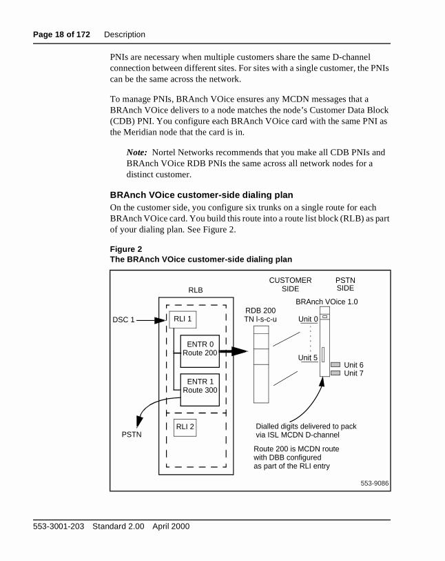
PNIs are necessary when multiple customers share the same D-channeconnection between different sites. For sites with a single customer, the Pcan be the same across the network.
To manage PNIs, BRAnch VOice ensures any MCDN messages that a BRAnch VOice delivers to a node matches the node’s Customer Data Bl(CDB) PNI. You configure each BRAnch VOice card with the same PNI the Meridian node that the card is in.
Note: Nortel Networks recommends that you make all CDB PNIs anBRAnch VOice RDB PNIs the same across all network nodes for a distinct customer.
BRAnch VOice customer-side dialin g planOn the customer side, you configure six trunks on a single route for eachBRAnch VOice card. You build this route into a route list block (RLB) as paof your dialing plan. See Figure 2.
Figure 2The BRAnch VOice customer-side dialing plan
Unit 0
Unit 5
BRAnch VOice 1.0 RDB 200TN l-s-c-u
ENTR 0Route 200
ENTR 1Route 300
RLI 1
PSTNRLI 2
DSC 1
RLB
Dialled digits delivered to packvia ISL MCDN D-channel
Route 200 is MCDN routewith DBB configuredas part of the RLI entry
PSTNSIDE
CUSTOMERSIDE
Unit 6Unit 7
553-9086
553-3001-203 Standard 2.00 April 2000

Description Page 19 of 172
text
TN all nit 7 the TN and
ce ility
e
to
BRAnch VOice PSTN-side dialin g planOn the PSTN side, consider BRAnch VOice call management in the conof outgoing and incoming calls. See Figure 3.
Outgoing calls For outgoing calls, the Meridian 1 sends a call to one ofunits 0 to 5 on the BRAnch VOice card. BRAnch VOice then starts a PScall using either unit 6 or 7. If one of the destinations must provide non-cassociated services, then BRAnch VOice can be configured to reserve ufor the PSTN connection to the HQ/tandem node. If the call destination isHQ/tandem node, then BRAnch VOice starts a call using unit 7, the lastavailable. BRAnch VOice dials the access code of the ISDN PSTN trunk the PSTN call starts.
If the Meridian 1 requests a call to a third destination, then BRAnch VOirejects the call with cause “No channel/circuit available”. BRAnch VOicesupports up to six calls to an HQ/tandem node, depending on the availabof BRAnch VOice’s second PSTN-side trunk.
Configure each BRAnch VOice card with an HQ PSTN number (see “BRAnch VOice configuration description” on page 88). If a BRAnch VOiccannot deliver voice or NCA messaging on a direct, point-to-point connection, the BRAnch VOice establishes a different PSTN connectionthe HQ/tandem node by referencing the HQ PSTN number.
Figure 3The BRAnch VOice PSTN-side dialing plan
4
BRAnch VOice 1.0
Route 1 (any location)
Route 2
(HQ/tandem node only)
Outgoing call
Incoming call
BRAnch VOice translation
DSC PSTN #
001-7345-4567
Unit 5Unit 6
Unit 7
Route 3
553-9087
Unit 0
Meridian BRAnch VOice 1.0 Description, Installation, and Operation
Page 20 of 172 Description
de,
Bs. a ays
l ber is es
rom then
ers ber e ich igit ide es to
51
ting re, e N
If users do not specify one of the destinations as being a HQ/tandem noBRAnch VOice can support any two destinations.
Incoming calls Incoming calls, in general, can be directed towards BRAnch VOice’s PSTN-side routes using trunk steering codes and the RLIn the event of an incoming call from a HQ location, calls are directed to route associated with unit 7. This ensures calls related to the HQ are alwhandled by the same PSTN-side trunk.
This is done by providing two PSTN numbers for branches if HQ channereservation is used. One number is used by other branches and one numreserved for incoming calls from the HQ. Incoming calls from other branchare never directed towards the unit reserved for HQ calls. Incoming calls fthe HQ are first directed towards the HQ reserved unit, and if this is busy, towards the other PSTN units.
Note: BRAnch VOice can operate with either DID or non-DID PSTNconnectivity.
In the Figure 4 example, a call is coming in from the HQ. The PSTN delivthe full DN including the area code (091). In this situation, the PSTN numcan be stripped off by using the OVLR prompt associated with the ISDNroute. If the OVLR prompt is set to YES, then the user is prompted for thnumber of digits to delete. The number delivered in this case is 6321, whis associated with a Trunk Steering Code (TSC) using an Incoming DID DConversion (IDC) table. The IDC table directs the call towards the PSTN sunit using a TSC. This method has the advantage of not using access coddirect incoming calls. Refer to “Engineer BRAnch VOice cards” on pagefor more information.
If the user hears a buzzing noise, this means the BRAnch VOice is attempto initiate a Point-to-Point Protocol (PPP) session and the call is, therefoterminating correctly. This can also be verified by putting a monitor on thMCDN D-Channel (DCH) and also using Overlay 32 to check which PSTunit went busy.
553-3001-203 Standard 2.00 April 2000

Description Page 21 of 172
s are to 4
a
ting ting H
(for ion.
h
lls
Checkin g the Dial PlanUsers can make a quick check that the dialing plan, IDC tables, and TSCworking correctly by simply dialing the PSTN using the DID number usedtarget BRAnch VOice. For example, to check the dialing plan that Figureshows, a user dials the PSTN access code and then 091-7456321 fromnormal set on the customer network.
If the user hears a buzzing noise, this means the BRAnch VOice is attempa Point-to-Point Protocol (PPP) session and the call is, therefore, terminacorrectly. This can also be verified by putting a monitor on the MCDN DCand using Overlay 32 to check which PSTN unit went busy.
If the user does not hear a buzzing noise and instead receives ringbackexample) then the IDC, the TSC, etc., do not have the correct configurat
Note: This procedure is a test only and is not part of normal BRAncVOice operation.
Avoidin g glare situationsGlare occurs when an incoming and outgoing call contend for the same customer side trunk. BRAnch VOice has outgoing calls presented to its customer side trunks, and BRAnch VOice, in turn, presents incoming ca
Figure 4Terminating a PSTN call on a BRAnch VOice
Unit 0
BRAnch VOice 1.0
Route 1
Route 2
Unit 5Unit 6
Unit 7
Route 3
PSTN
091-7456321
IncomingcallPRI or BRI card
Non-DID route
IDC table
6321 -> TSC
other entry
other entry
553-9088
Meridian BRAnch VOice 1.0 Description, Installation, and Operation
Page 22 of 172 Description
re
e e
the
een . If both ,
alls
If
e
ils ard.
he the H, next
h as ures
xt
from branches on the same set of customer-side trunks. To minimize glasituations, the BRAnch VOice customer side trunk members should be configured as linear search (top-down) in the BRAnch VOice route data block. The SRCH prompt in Overlay 16 specifies how trunk members arselected. BRAnch VOice ensures that incoming calls are presented to thcustomer-side units using a linear search method (bottom up).
If a new outgoing call arrives at the same time as a new incoming call ispresented to BRAnch VOice, BRAnch VOice always gives precedence tonew incoming call and rejects the outgoing call with a cause of “No channel/circuit available”.
Glare can occur between a HQ and a branch if there is no existing call betwthe HQ and branch; there is only one idle PSTN unit on the HQ BRAnchVOice and only the HQ reserved unit on the branch BRAnch VOice is idleboth the HQ and branch attempt to call each other at the same time, thencalls fail with cause busy. For voice call setup, this is not a major problembecause both voice calls can simply drop back to PSTN. However, if the cwere being set up to deliver an MCDN facility message, then this is a problem. The solution is to retry call setup after a short random interval. both HQ and branch release and retry several times after short random intervals, the chances of one side connecting are high and delivery of thMCDN facility message practically guaranteed.
Abnormal o perationAbnormal operation includes situations where the BRAnch VOice card faor a technician inadvertently and physically removes a BRAnch VOice c
In either case, the BRAnch VOice DCH goes to a RLS state. However, tBRAnch VOice trunks remain in an IDLE state. If a call is presented whencard has failed or been removed, call processing first checks for the DCthen reverts to analog EXUT signaling, and then eventually reverts to the route in the route list block. This can take up to 10 seconds.
However, the trunks can be disabled by using maintenance routines, sucOverlay 30 running in the background at regular intervals. Overlay 30 ensany Enhanced Extended Universal Trunk (EXUT) units (that are not responding) are placed into a disabled state. New calls default to the neroute in the RLB immediately.
553-3001-203 Standard 2.00 April 2000

Description Page 23 of 172
ingle
e nnel
he cility ndem
nels route oute
hat
for
and
6 is ich
he
Multiple-card branches Large branch offices can have multiple BRAnch VOice cards. External access to these BRAnch VOice cards from other branches is through a sPSTN phone number. The TSC and RLB are used to direct calls to the multiple cards.
If HQ channel reservation is required for transport of MCDN non-call associated facility message associated with centralized services from a HQ/tandem node, then the HQ channel should be reserved on one of thcards. Facility messages for centralized services are sent over the D-chaassociated with the first route in the RLB. If the BRAnch VOice card with tHQ reserved channel is accessed by the first route in the RLB, then the famessages are routed to this card and guaranteed a channel to the HQ/tanode.
Therefore, the first card in a multi-card branch must have its PSTN chanseparated with one channel in the HQ route and the other in the standardlist. All other cards can have both their PSTN channels in the standard rlist.
Note: There is no inter-card communication between multiple cards treside in the same branch.
Figure 5 illustrates the configuration of multiple cards in a single branch.Refer to “Engineer multiple BRAnch VOice cards in a branch” on page 56further information on multiple-card branches.
BRAnch VOice branch ID and card ID Each BRAnch VOice card must have a unique combination of branch ID card ID. A Meridian BRAnch VOice 1.0 network can have up to 1,024 branches (numbered 0-1023). Each branch can logically contain up to 1cards (numbered 0-15). This unique branch ID and card ID combinationnecessary so that the PPP driver can configure unique IP addresses, whreside in separate subnets, for each end of every possible point-to-pointconnection in the network. The customer configures the branch ID and tcard ID in the CLI.
Refer to “BRAnch VOice branch ID and card ID” on page 47 for more information.
Meridian BRAnch VOice 1.0 Description, Installation, and Operation

Page 24 of 172 Description
) dec ce
for
to
s:
alls he
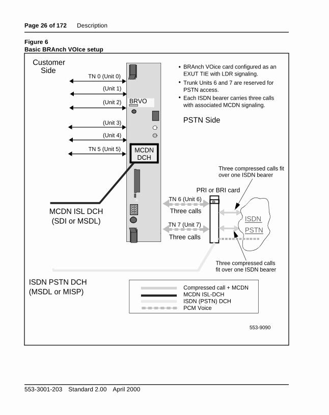
BRAnch VOice functional descri ption The BRAnch VOice card emulates an Enhanced Universal Trunk (EXUTcard supporting eight TIE trunk units. BRAnch VOice uses the G.729A coto make 8:1 (64 kb/s to 8 kb/s) compression on voice calls. BRAnch VOican route up to three voice (or fax) calls through one PSTN call to the destination BRAnch VOice. Bandwidth in the PSTN call is also necessarycall control, MCDN signaling, and overhead that is a result of voice packetization. One ISL D-channel connects to each BRAnch VOice cardprovide the MCDN signaling control for the eight trunk units.
The BRAnch VOice card partitions the eight available trunk units as follow
• The first six units (TNs 0-5) present uncompressed voice calls to andfrom the customer side. See Figure 6.
• The last two units (TNs 6 and 7) transport the compressed voice/fax cover the PSTN side using BRI/PRI ISDN bearer 64 kbps channels. Tcompressed voice/fax calls function as a data call while on the ISDNbearer.
Figure 6 illustrates the basic BRAnch VOice card setup.
Figure 5Multiple BRAnch VOice cards in a single branch
Unit 0
Unit 5
BRAnch VOice 1.0
BRAnch VOice 1.0
BRAnch VOice 1.0
Multiplecardsin onebranch
553-9089
Just oneHQ routeper branchis necessary
Unit 0
Unit 5
Unit 0
Unit 5
Route 1, Route 2
Route 3, Route 4
Route 5, Route 6
553-3001-203 Standard 2.00 April 2000

Description Page 25 of 172
Q es
N can
Note: For a BRAnch VOice card at a branch, unit 7 must route to the Hto guarantee delivery of MCDN signaling (only if the customer reserva HQ connection). Unit 6 can route to either the HQ or to another location.
BRAnch VOice can interface to either BRI or PRI ISDN hardware for PSTaccess. If the customer has PRI hardware, multiple BRAnch VOice cardsaccess the same ISDN PRI route for PSTN access.
Meridian BRAnch VOice 1.0 Description, Installation, and Operation
Page 26 of 172 Description
Figure 6Basic BRAnch VOIce setup
BRVO
A:
BRAnch VOice card configured as anEXUT TIE with LDR signaling.
MCDNDCH
TN 0 (Unit 0)
(Unit 1)
(Unit 2)
(Unit 3)
(Unit 4)
TN 5 (Unit 5)
TN 6 (Unit 6)
TN 7 (Unit 7)
Customer Side
ISDN
PSTN
PRI or BRI card
Three compressed calls fitover one ISDN bearer
Three compressed callsfit over one ISDN bearer
MCDN ISL DCH(SDI or MSDL)
ISDN PSTN DCH(MSDL or MISP)
Three calls
Three calls
PSTN Side
Compressed call + MCDNMCDN ISL-DCHISDN (PSTN) DCHPCM Voice
553-9090
Trunk Units 6 and 7 are reserved forPSTN access. Each ISDN bearer carries three callswith associated MCDN signaling.
553-3001-203 Standard 2.00 April 2000

Description Page 27 of 172
l with
g
rate
Note 1: BRAnch VOice uses the G.729A codec, which provides calcompression from 64 kbps to 8 kbps. The codec frame size is 20 ms voice activity detection set to ON.
Note 2: If the D-channel fails, BRAnch VOice re-routes calls accordinto the customer’s Meridian 1 dialing plan.
Note 3: BRAnch VOice supports any combination of up to three simultaneous voice and fax calls per PSTN call. The PSTN call has aof 64 kbps. Each fax can have a maximum rate of 9600 bps.
Note 4: BRAnch VOice cannot use analog PSTN connectivity; i.e., BRAnch VOice cannot access analog bearers.
Note 5: BRAnch VOice does not support data modem calls.
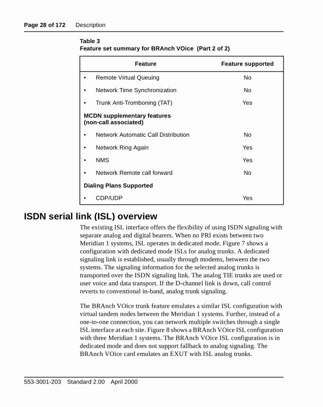
Feature set summar y for BRAnch VOiceTable 3 lists common features that are relevant to BRAnch VOice and whether BRAnch VOice supports them.
Table 3Feature set summary for BRAnch VOice (Part 1 of 2)
Feature Feature supported
MCDN supplementary features(call associated)
• Calling line ID Yes
• Network call redirection, call transfer/forward/hunting
Yes
• Network Attendant Services (NAS)(NAS slow answer recall, NAS camp-on, NAS call waiting, incoming call indication, NAS equal distribution, NAS anti-tromboning, and NAS Drop Back Busy)
all
• Trunk Route Optimization (TRO) Yes
• Network Call Trace (NCT) No
Meridian BRAnch VOice 1.0 Description, Installation, and Operation
Page 28 of 172 Description
h
or
th of a gle ion n
ISDN serial link (ISL) overview The existing ISL interface offers the flexibility of using ISDN signaling witseparate analog and digital bearers. When no PRI exists between two Meridian 1 systems, ISL operates in dedicated mode. Figure 7 shows a configuration with dedicated mode ISLs for analog trunks. A dedicated signaling link is established, usually through modems, between the two systems. The signaling information for the selected analog trunks is transported over the ISDN signaling link. The analog TIE trunks are useduser voice and data transport. If the D-channel link is down, call control reverts to conventional in-band, analog trunk signaling.
The BRAnch VOice trunk feature emulates a similar ISL configuration wivirtual tandem nodes between the Meridian 1 systems. Further, instead one-to-one connection, you can network multiple switches through a sinISL interface at each site. Figure 8 shows a BRAnch VOice ISL configuratwith three Meridian 1 systems. The BRAnch VOice ISL configuration is idedicated mode and does not support fallback to analog signaling. The BRAnch VOice card emulates an EXUT with ISL analog trunks.
• Remote Virtual Queuing No
• Network Time Synchronization No
• Trunk Anti-Tromboning (TAT) Yes
MCDN supplementary features(non-call associated)
• Network Automatic Call Distribution No
• Network Ring Again Yes
• NMS Yes
• Network Remote call forward No
Dialing Plans Supported
• CDP/UDP Yes
Table 3Feature set summary for BRAnch VOice (Part 2 of 2)
Feature Feature supported
553-3001-203 Standard 2.00 April 2000

Description Page 29 of 172
e
a n.
the the
ls se of g
BRAnch VOice call setup With BRAnch VOice, two PSTN-side calls can be set up to two differentlocations or the same location. When the first call seizes a customer-sidBRAnch VOice trunk TN, the following events occur:
1 A PSTN call is initiated to the far end
2 A PPP session is set up
3 An H.323 call is placed
MCDN signaling is encapsulated within the H.323 call. If the next call is todifferent location, another PSTN call is initiated to the other switch locatioAgain, the PPP session and the H.323 call follow. Voice calls to each oftwo different locations use the PSTN calls that are already in place, up tothree voice call per PSTN call limit.
However, if a call to a third location is routed to BRAnch VOice while calare established to two other locations, the card rejects the call with a cau“No channel/circuit available”. The switch can then re-direct the call usinthe next route in its Route List Index.
Figure 7Dedicated mode ISL with analog trunks
MSDL
Analog
modem
Trunks
MSDL
AnalogTrunks
Meridian 1Meridian 1
TIE TIE
modem
PSTN
ISLISL
553-9091
Meridian BRAnch VOice 1.0 Description, Installation, and Operation

Page 30 of 172 Description
Figure 8BRAnch VOice ISL configuration
ISL
MSDL
BRAVO
Meridian 1
ISL
MSDL
BRAVO
Meridian 1
ISL
MSDL
BRAVO
Meridian 1
ISDN PSTN
553-9514
- PCMCIA supplies the ISL connectivity
- ISL controls the BRAnch VOice EXUT trunk members
- One ISL connection per BRAVO
- BRAnch VOice cards do not share ISL D-channels
553-3001-203 Standard 2.00 April 2000

Description Page 31 of 172
nch ain,
e ds. fter
sage. all
ore
the
rk. l r:
ll
ute
an
End-of-Call Timeout parameterBRAnch VOice provides customers that require MCDN services an opportunity to reduce costs associated with expensive leased lines. BRAVOice occasionally opens PPP connections for the transport of non-callassociated messaging. MCDN features, such as Network-Wide Ring Agactivate non-call associated messaging.
For optimum performance, the customer can define a timer that keeps thPSTN call up for a configurable length of time after the last voice call enThere is also a built-in timer that keeps the PSTN call up for six seconds athe BRAnch VOice card has sent or received a non-call associated mesThe built-in timer keeps the PSTN call up to allow for a reply to the non-cassociated message.
BRAnch VOice fallback to alternative routesBRAnch VOice cannot handle the simultaneous placement of calls to mthan two locations through a single BRAnch VOice card. If the system attempts to place a call to a third location through a BRAnch VOice card,BRAnch VOice card rejects the call with a cause of “No channel/circuit available”. This cause enables the MCDN Drop Back Busy feature to woYou use the Meridian 1 dialing plan to determine where the call must falback to. There are three fallback scenarios that you can use in any orde
• Fallback to the same BRAnch VOice card, to attempt to route the cathrough the HQ node
• Fallback to another BRAnch VOice card, to search for an available roto the desired location
• Fallback to the PSTN, to use a standard, non-BRAnch VOice trunk
Figure 9 gives an example of when a BRAnch VOice call must fall back toalternative route.
1 A call is initiated from location D to location A. One of the BRAnch VOice PSTN-side trunks is set up to location A.
2 Another call is presented to BRAnch VOice in location D. This call requires a connection to location B. The second PSTN-side trunk onBRAnch VOice is set up to location B.
Meridian BRAnch VOice 1.0 Description, Installation, and Operation

Page 32 of 172 Description
l s the
r in
lls ch call els
3 A third call is presented to the BRAnch VOice in location D. This calrequires a connection to location C. However, the BRAnch VOice haalready used all of its PSTN side trunks. The BRAnch VOice rejects call with a cause of “No circuit/channel available”.
4 The call continues according to the next route in the RLB.
The need for BRAnch VOice fallback to alternative routes can also occuinstallations with three or more branches. For example, there are three branches, each with a single BRAnch VOice card. There are six voice ca(two PSTN calls) set up between two of the branches so that their BRAnVOices have no available channels. A user in the third branch attempts toone of the other branches. The BRAnch VOice card has available chann
Figure 9Example of BRAnch VOice fallback to an alternative route
~~~~
~~~~
~~~~
Location A
Location B
Location C
Route List Index
BRAnch VOice Route (100)
PRI or BRI Route (200)
DISC (DBB)
1.
2.
3.
4.
Location D
PRI or BRI card
PSTN
Route100
Route100
553-9092
BRVO
Meridian 1
Meridian 1
Meridian 1
Unit 6Unit 7
Unit 0
Unit 5
553-3001-203 Standard 2.00 April 2000
Description Page 33 of 172
d the use
o l.
are
of n be
duct t is erial ly
ch
e p
lso to ing the
and makes the external PSTN call. The PSTN call does not complete, anoriginal call reroutes to the next entry in the Route List Index with the ca“No channel/circuit available”.
Return to BRAnch VOice networkWhen the BRAnch VOice failure is recoverable, all new outgoing calls gthrough the BRAnch VOice network when the situation is back to normaWhen all new calls are processed through BRAnch VOice cards, call connections that were established under the “Drop Back Busy” conditionnot affected.
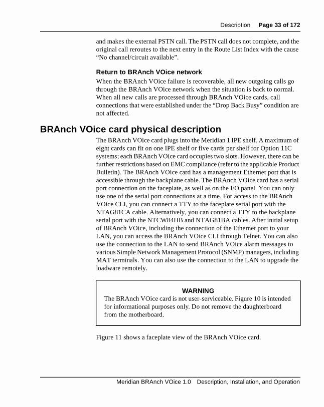
BRAnch VOice card physical descri ption The BRAnch VOice card plugs into the Meridian 1 IPE shelf. A maximumeight cards can fit on one IPE shelf or five cards per shelf for Option 11Csystems; each BRAnch VOice card occupies two slots. However, there cafurther restrictions based on EMC compliance (refer to the applicable ProBulletin). The BRAnch VOice card has a management Ethernet port thaaccessible through the backplane cable. The BRAnch VOice card has a sport connection on the faceplate, as well as on the I/O panel. You can onuse one of the serial port connections at a time. For access to the BRAnVOice CLI, you can connect a TTY to the faceplate serial port with the NTAG81CA cable. Alternatively, you can connect a TTY to the backplanserial port with the NTCW84HB and NTAG81BA cables. After initial setuof BRAnch VOice, including the connection of the Ethernet port to your LAN, you can access the BRAnch VOice CLI through Telnet. You can ause the connection to the LAN to send BRAnch VOice alarm messages various Simple Network Management Protocol (SNMP) managers, includMAT terminals. You can also use the connection to the LAN to upgrade loadware remotely.
Figure 11 shows a faceplate view of the BRAnch VOice card.
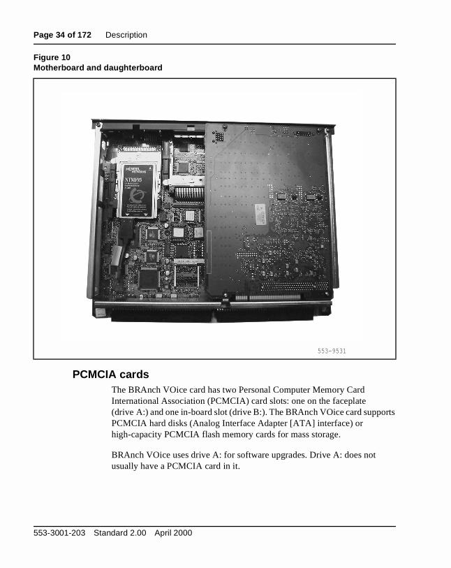
WARNINGThe BRAnch VOice card is not user-serviceable. Figure 10 is intendedfor informational purposes only. Do not remove the daughterboard from the motherboard.
Meridian BRAnch VOice 1.0 Description, Installation, and Operation
Page 34 of 172 Description
rts
PCMCIA cards The BRAnch VOice card has two Personal Computer Memory Card International Association (PCMCIA) card slots: one on the faceplate (drive A:) and one in-board slot (drive B:). The BRAnch VOice card suppoPCMCIA hard disks (Analog Interface Adapter [ATA] interface) or high-capacity PCMCIA flash memory cards for mass storage.
BRAnch VOice uses drive A: for software upgrades. Drive A: does not usually have a PCMCIA card in it.
Figure 10Motherboard and daughterboard
553-9531
553-3001-203 Standard 2.00 April 2000

Description Page 35 of 172
e he H
Part of the BRAnch VOice package is the D-channel PCMCIA card (NTWE07AA). This PCMCIA card resides in drive B: of the BRAnch VOiccard and provides an RS-422 link to the MSDL card (large systems) or tSDI/DCH card (Option 11C) in the Meridian 1. The MSDL and the SDI/DCcards provide the ISL D-channel interface to the BRAnch VOice card.
Figure 11BRAnch VOice card faceplate
BRVOStatus LED
4-character LED alphanumeric display
RS-232 maintenance port
Shortened lock latches
Reset button
Type III PCMCIA slot(drive A:)
10/100Base-T voice port Voice
Ethernet activity LEDs
(unused on the BRAnch VOice card)
Engineering code and release labelNTCW98AARLS 01
553-9093
Meridian BRAnch VOice 1.0 Description, Installation, and Operation

Page 36 of 172 Description
Supported interfaces Table 4 is a summary of the interface types that a BRAnch VOice card supports.
Table 4Interface summary
Interface Number of connections
DS-30X 1
Card LAN 1
Enhanced IDE 1 (see Note 1)
PCMCIA card (Standard) 2 Type III
Ethernet 2 (see Note 2)
Maintenance RS-232 2
Note 1: This interface is part of the BRAnch VOice card architecture, but BRAnch VOice does not use this interface.
Note 2: BRAnch VOice uses only one of the two Ethernet interfaces—the management interface. BRAnch VOice does not use the Ethernet voice interface (network port).
553-3001-203 Standard 2.00 April 2000

Page 37 of 172
60
unk
ls. TN o oice to
rk
Engineering guidelinesSystem Engineering (553-3001-151) describes Meridian 1 general systemengineering guidelines. The following information provides engineering guidelines only to plan and implement the Meridian BRAnch VOice 1.0 application.
X11 system software requirements The BRAnch VOice card emulates an Enhanced Extended Universal Tr(EXUT) card supporting eight TIE trunk units. BRAnch VOice uses the G.729A codec to make 8:1 (64 kb/s to 8 kb/s) compression on voice calBRAnch VOice can route up to three voice (or fax) calls through one PScall to the destination BRAnch VOice. Bandwidth in the PSTN call is alsnecessary for call control, MCDN signaling, and overhead as a result of vpacketization. One ISL D-channel connects to each BRAnch VOice cardprovide the MCDN signaling control for the eight trunk units.
The customer uses the following software overlays to configure each BRAnch VOice card:
• Overlay 16 to configure two or three TIE routes
• Overlay 17 to configure the D-channel
• Overlay 14 to configure the eight TIE trunks
• Overlays 86, 87, and 90 to configure the dialing plan, such as NetwoAlternate Route Section (NARS)/Basic Alternate Route Selection (BARS)/Coordinated Dialing Plan (CDP), within the private network
Meridian BRAnch VOice 1.0 Description, Installation, and Operation

Page 38 of 172 Engineering guidelines
To support the BRAnch VOice functions, the Meridian 1 system must runX11 release 22 or later software. Table 1 lists the X11 software packagerequirements for BRAnch VOice.
Table 1X11 software package requirements for BRAnch VOice
Package mnemonic
Package number
Package description Comment
ISDN1 145 ISDN Base Required
ISL1 147 ISDN Signaling Link Required
BARS 57 Basic Alternate Route Selection Either this or NARS required
NARS 58 Network Alternate Route Selection Either this or BARS required
CDP 59 Coordinated Dialing Plan Not required if using UDP
NAS 159 Network Attendant Services Required for NAS functionality
ORC/RVQ1 192 Remote Virtual Queuing Required for fallback operation
FNP 160 Flexible Number Plan Optional
MCDN2 The Meridian Customer Defined Network feature set, including NAS, TRO, TAT, NMS, etc.
Optional
IDC 113 Incoming Digit Conversion Optional, but required for IDC operation
NFCR 49 New Flexible Code Restriction Optional, but required for IDC operation
DNWK4 231 DPNSS network services Required for fallback operation prior to Rls 24
Note 1: The ISDN (145) and ISL (147) packages are necessary for basic BRAnch VOice operation. For fallback operation, BRAnch VOice requires the Drop Back Busy (DBB) feature. Drop Back Busy depends on ISDN (145) and ORC/RVQ (192).
Note 2: MCDN is a collection of packages that enable individual features.
Note 3: Package 176 (DID to TIE package) is “restricted” in the European market; the “DITI” prompt in LD 15 must be “YES”.
Note 4: Package 231 is required for SBOC operation prior to Rls 24—the SBOC functionality required by BRAnch VOice has been incorporated into Rls 24.
553-3001-203 Standard 2.00 April 2000

Engineering guidelines Page 39 of 172
ne In lots
Hardware requirements Meridian 1 hardware requirements
The BRAnch VOice card takes up two slots and connects to the backplaonly in the left-hand slot and it is in this slot where it must be configured.an IPE shelf, you can connect a BRAnch VOice card to the backplane in s0-6 and 8-15. It is important to know which card slot you connected a BRAnch VOice card to when configuring the trunks. Figure 12 shows thelarge systems (Options 51C-81C) hardware requirements.
Figure 12Meridian 1 large systems hardware requirements
BRVO
MSDL
Management LAN
CE Shelf
Large System
553-9094
Cable
IPE Shelf
Two slots
Meridian BRAnch VOice 1.0 Description, Installation, and Operation
Page 40 of 172 Engineering guidelines
t on
et ch
n 1 ary ch
You must wire the I/O panel correctly to access the serial ports, which exithe high tip/ring pairs. Install the BRAnch VOice card into one of the available slots listed in Table 2.
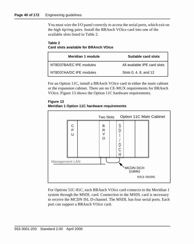
For an Option 11C, install a BRAnch VOice card in either the main cabinor the expansion cabinet. There are no CE-MUX requirements for BRAnVOice. Figure 13 shows the Option 11C hardware requirements.
For Options 51C-81C, each BRAnch VOice card connects to the Meridiasystem through the MSDL card. Connection to the MSDL card is necessto receive the MCDN ISL D-channel. The MSDL has four serial ports. Eaport can support a BRAnch VOice card.
Table 2Card slots available for BRAnch VOice
Meridian 1 module Suitable card slots
NT8D37BA/EC IPE modules All available IPE card slots
NT8D37AA/DC IPE modules Slots 0, 4, 8, and 12
Figure 13Meridian 1 Option 11C hardware requirements
Management LAN
B R V O
CPU
Option 11C Main Cabinet
Two Slots
MCDN DCH(cable)
SDI/DCH
553-9095
553-3001-203 Standard 2.00 April 2000

Engineering guidelines Page 41 of 172
he
n
net
For Option 11C, the SDI/DCH (NTAK02BB or later) card supplies the MCDN ISL D-channel. The SDI/DCH card requires an additional slot in tmain cabinet with a CE-MUX connection. The SDI/DCH can support twoBRAnch VOice cards.
To help you determine your Meridian 1 hardware requirements, Nortel Networks recommends:
• BRAnch VOice requires access to the PSTN through ISDN PRI/BRItrunks. Make sure non-BRAnch VOice calls requiring access to the PSTN do not block the BRAnch VOice card(s) from generating or receiving PSTN calls.
• Install BRAnch VOice cards in different IPE shelves to minimize theimpact of a single IPE shelf failure. This is particularly important for tandem/HQ nodes.
• Include some PSTN trunks with your BRAnch VOice trunks in each network group. Include PSTN trunks to limit intergroup switching whea call to a BRAnch VOice trunk must fall back to a PSTN trunk.
• For Option 11C, place the BRAnch VOice card in the expansion cabito save space in the main cabinet.
Meridian BRAnch VOice 1.0 Description, Installation, and Operation

Page 42 of 172 Engineering guidelines
h
e C.
l
BRAnch VOice hardware requirementsTable 3 lists the hardware requirements for BRAnch VOice. Each BRAncVOice order consists of one of each of these items.
Note: The D-channel interconnect cable (NTMF04BA or NTWE04AC/AD) that you receive depends on whether you install thBRAnch VOice in a large system (Options 51C-81C) or an Option 11
Note: The NT8D81AA cable brings all 24 tip/ring pairs to the I/O paneand connects to the NTCW84HB cable.
Table 3BRAnch VOice hardware requirements
Component Description
NTCW98AA BRAnch VOice card
An IPE card that provides an integrated way to extend key Meridian 1 features to one or more branch offices.
NTWE07AA D-channel PCMCIA interface card
PCMCIA card that provides an interface between the BRAnch VOice card and the D-channel handler in the system.
NTCW84EA pigtail cable
Cable connects port 0 of the PCMCIA card to a header on the motherboard to enable you to establish a link to the D-channel handler.
NTCW84HB I/O panel cable.
Cable provides access to four ports on the BRAnch VOice card: a serial maintenance port, a management LAN port, a D-channel port, and a serial data port (for CDR data collection).
NTMF04BA extension cable (large systems only)
This extension cable connects the NTCW84HB from the BRAnch VOice card to the NTND26 from the MSDL card.
NTWE04AC/AD SDI/DCH interconnect cable (Option 11 only)
This cable connects the NTCW84HB from the BRAnch VOice card to the NTAK19FB cable from the SDI/DCH card. The AC is a 10-foot (3 m) intercabinet version, and the AD is a 1-foot (30 cm) intracabinet version.
553-3001-203 Standard 2.00 April 2000
Engineering guidelines Page 43 of 172
ch
r
and
k.
he
External equipment requirementsTo interface with the BRAnch VOice card, you must access the CLI, whienables you to:
• configure the BRAnch VOice card
• perform maintenance and diagnostics on the card
To access the CLI, you must use a VT100 terminal or a PC emulating aVT100 terminal, or establish a Telnet session. There are three options foconnecting a terminal to the BRAnch VOice card:
• directly through a serial connection
• remotely through a modem connection
• connect the BRAnch VOice card to the LAN
You must set the terminal interface to 9600 baud, 8 data bits, 1 stop bit,no parity.
BRAnch VOice networking configurationsThe customer can deploy BRAnch VOice in three different networking configurations:
• Branch/HQ node—Select this configuration if most of the call traffic isbetween the branch and the HQ with very little inter-branch traffic.
• Branch/HQ cluster—Select this configuration if there is a fairly evenmix of branch/HQ and inter-branch call traffic.
• Extension of the MCDN network—This configuration enables a customer to extend an MCDN network by using a BRAnch VOice lin
The following three sections provide further details on these networking configurations.
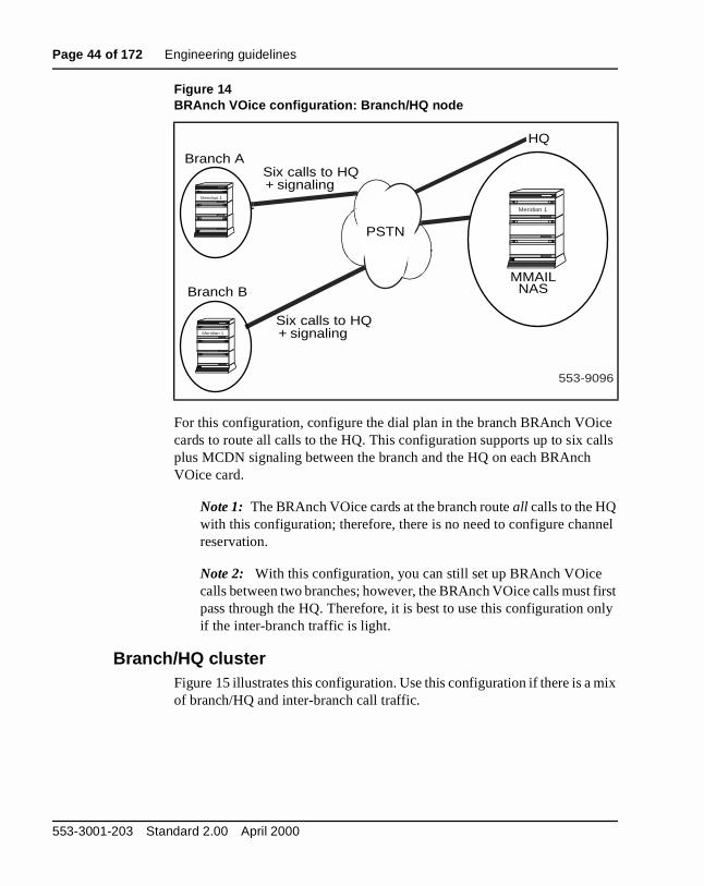
Branch/HQ nodeFigure 14 illustrates this configuration. Use this configuration if most of tBRAnch VOice traffic is between the branch and the HQ.
Meridian BRAnch VOice 1.0 Description, Installation, and Operation
Page 44 of 172 Engineering guidelines
e lls
el
irst nly
ix
For this configuration, configure the dial plan in the branch BRAnch VOiccards to route all calls to the HQ. This configuration supports up to six caplus MCDN signaling between the branch and the HQ on each BRAnch VOice card.
Note 1: The BRAnch VOice cards at the branch route all calls to the HQ with this configuration; therefore, there is no need to configure channreservation.
Note 2: With this configuration, you can still set up BRAnch VOice calls between two branches; however, the BRAnch VOice calls must fpass through the HQ. Therefore, it is best to use this configuration oif the inter-branch traffic is light.
Branch/HQ clusterFigure 15 illustrates this configuration. Use this configuration if there is a mof branch/HQ and inter-branch call traffic.
Figure 14BRAnch VOice configuration: Branch/HQ node
HQ
Six calls to HQ+ signaling
Six calls to HQ+ signaling
Branch A
Branch BMMAILNAS
553-9096
Meridian 1
Meridian 1
Meridian 1
PSTN
553-3001-203 Standard 2.00 April 2000

Engineering guidelines Page 45 of 172
ast
ed as
alls hes
h sed
For this configuration, configure the HQ channel reservation flag in at leone BRAnch VOice card in each branch. This guarantees delivery of centralized MCDN services to each branch. NRAG messages are deliverlong as there is a free voice channel available on the selected route.
With this configuration, each BRAnch VOice supports up to three direct cbetween the locations. If necessary, BRAnch VOice calls between branccan also travel through the HQ/tandem node.
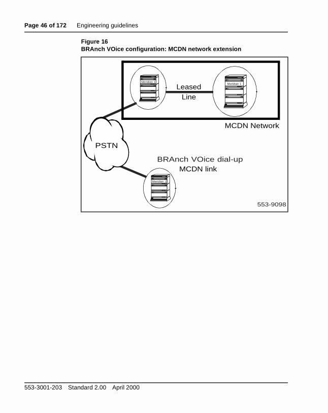
MCDN network extensionFigure 16 illustrates the MCDN network extension configuration. BRAncVOice uses the PSTN to route calls and MCDN signaling instead of a lealine. Therefore, you do not need an additional leased line to extend yourMCDN network to a branch.
Figure 15BRAnch VOice configuration: Branch/HQ cluster
MMAILNAS
Branch A
Branch B
HQ/tandemnode
Three calls+ signaling to HQand three calls toany other node
553-9097
Meridian 1
Meridian 1
PSTN
Meridian 1
Meridian BRAnch VOice 1.0 Description, Installation, and Operation
Page 46 of 172 Engineering guidelines
Figure 16BRAnch VOice configuration: MCDN network extension
MCDN Network
MCDN link
LeasedLine
BRAnch VOice dial-up
553-9098
Meridian 1Meridian 1
Meridian 1
PSTN
553-3001-203 Standard 2.00 April 2000

Engineering guidelines Page 47 of 172
ely
16 ue in
ve not
der
nch he
ll to ains ce ause ation
BRAnch VOice networking guidelinesThe following sections describe general networking guidelines to effectivoperate a BRAnch VOice multi-node network.
BRAnch VOice branch ID and card IDA BRAnch VOice network can contain up to 1,024 branches, or nodes, including the HQ/tandem node. Each branch can logically contain up to BRAnch VOice cards. BRAnch VOice identifies each branch with a uniqbranch ID number (0-1023); and BRAnch VOice identifies each card witha branch with a card ID number (0-15).
Note: Each card in the BRAnch VOice network requires a unique branch ID and card ID combination. If any two cards in the network hathe same branch ID and card ID combination, the conflicting cards dointerwork. The conflict generates an SNMP alarm.
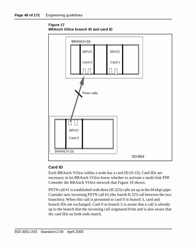
Branch ID Each BRAnch VOice network node has a unique branch ID and each BRAnch VOice within any node has a card ID in the range of 0-15. Consithe BRAnch VOice network that Figure 17 shows.
BRAnch VOice Card 0 in branch 3 makes a PSTN call to branch 0. Bothnodes exchange branch ID and card IDs after the PSTN call has been established. Each BRAnch VOice has a state table containing a list of braidentifiers with PSTN connections established. In the case of branch 3, tstate table contains the branch ID of branch 0.
Now BRAnch VOice card 0 at branch 3 receives a request to make a cathe PSTN number corresponding to branch 0. Each Dial Plan entry contboth a PSTN number and the branch ID of the destination. BRAnch VOiconsults its state table for any existing connections to the destination. Becthe state table has the current state of all PSTN calls (including the destinbranch ID), the BRAnch VOice knows whether a call to the requested destination already exists.
Meridian BRAnch VOice 1.0 Description, Installation, and Operation
Page 48 of 172 Engineering guidelines
P.
ipe. wo
ady that
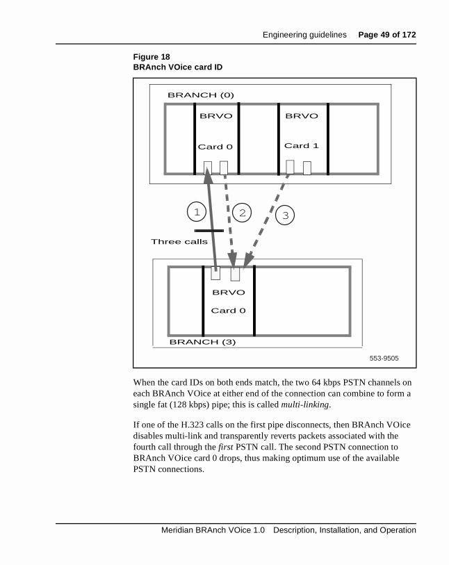
Card IDEach BRAnch VOice within a node has a card ID (0-15). Card IDs are necessary to let BRAnch VOice know whether to activate a multi-link PPConsider the BRAnch VOice network that Figure 18 shows.
PSTN call #1 is established with three (H.323) calls set up in the 64 kbps pConsider new incoming PSTN call #2 (the fourth H.323 call between the tbranches). When this call is presented to card 0 in branch 3, card and branch IDs are exchanged. Card 0 in branch 3 is aware that a call is alreup to the branch that the incoming call originated from and is also aware the card IDs on both ends match.
Figure 17BRAnch VOice branch ID and card ID
BRANCH (0)
Card 0
553-9504
Three calls
BRANCH (3)
BRVO BRVO
BRVO
Card 1Card 0
553-3001-203 Standard 2.00 April 2000
Engineering guidelines Page 49 of 172
s on a
ce
When the card IDs on both ends match, the two 64 kbps PSTN channeleach BRAnch VOice at either end of the connection can combine to formsingle fat (128 kbps) pipe; this is called multi-linking.
If one of the H.323 calls on the first pipe disconnects, then BRAnch VOidisables multi-link and transparently reverts packets associated with thefourth call through the first PSTN call. The second PSTN connection to BRAnch VOice card 0 drops, thus making optimum use of the available PSTN connections.
Figure 18BRAnch VOice card ID
BRVO BRVO
Card 0 Card 1
BRANCH (0)
Card 0
BRVO
Three calls
BRANCH (3)
553-9505
1 2 3
Meridian BRAnch VOice 1.0 Description, Installation, and Operation

Page 50 of 172 Engineering guidelines
TN ice
ID rk n
Now consider a new incoming PSTN call (#3 in Figure 18). When this PScall is established and branch and card IDs are exchanged, BRAnch VOcard 0 in branch 3 is aware that the card IDs do not match; hence, multi-link is not activated across the PSTN connections.
BRAnch VOice IP address reservationBRAnch VOice reserves two IP addresses for each branch ID and card combination. The branch IDs and card IDs tell the BRAnch VOice netwowhich IP addresses to use to establish point-to-point PSTN calls betweeBRAnch VOice cards. Table 4 lists the IP address that BRAnch VOice reserves for each branch ID and card ID combination.
Table 4BRAnch VOice IP address reservation scheme (Part 1 of 2)
Branch ID Card ID Unit numberLocal IP address
Terminating IP address
0 0 012.31
10.240.0.010.240.0.210.240.0.4.10.240.0.62
10.240.0.110.240.0.310.240.0.5.10.240.0.63
1 01.31
10.240.0.6410.240.0.66.10.240.0.126
10.240.0.6510.240.0.67.10.240.0.127
15 01.31
10.240.3.19210.240.3.194.10.240.3.254
10.240.3.19310.240.3.195.10.240.3.255
1 0 0.31
10.240.4.0.10.240.4.62
10.240.4.1.10.240.4.63
15 0.31
10.240.7.192.10.240.7.254
10.240.7.193.10.240.7.255
B (0 to 0x3FF) N (0 to 0xF) C (0 to 0x1F) --- ---
553-3001-203 Standard 2.00 April 2000

Engineering guidelines Page 51 of 172
d for
alls
Engineer BRAnch VOice cardsYou can engineer a BRAnch VOice network to make optimal use of the PSTN connections that the BRAnch VOice cards at each branch create.
Channel reservationIn certain call scenarios, a connection to a HQ/tandem node must be guaranteed to ensure delivery of NCA messaging. This is achieved by reserving a channel on BRAnch VOice. If customers do not want to guarantee delivery of NCA messaging, then channel reservation is not required. Channel reservation can be summarized as follows:
1 BRAnch VOice must be configured to call a HQ/tandem node to guarantee delivery of NCA messaging.
2 BRAnch VOice automatically uses channel 7 as the channel reserveaccess to the HQ/tandem node.
3 Channel 7 only calls a PSTN number associated with the HQ/tandemnode.
4 A BRAnch VOice that has channel reservation active is restricted tothree calls to any other branch, unless calls are directed via the HQ/tandem node.
5 A BRAnch VOice that has channel reservation active can make six cto the HQ/tandem node.
1023 15 0.31
10.255.255.192.10.255.255.254
10.255.255.193.10.255.255.255
Note 1: BRAnch VOice uses units 6 and 7 for PSTN connection. BRAnch VOice reserves the other units for future use.
Note 2: These IP addresses should be reserved for the BRAnch VOice network, and not used by any other devices on the same subnet as the BRAnch VOice card(s).
Table 4BRAnch VOice IP address reservation scheme (Part 2 of 2)
Branch ID Card ID Unit numberLocal IP address
Terminating IP address
Meridian BRAnch VOice 1.0 Description, Installation, and Operation

Page 52 of 172 Engineering guidelines
ing >5), arate e an
ch to em
t”
lls
ID
6 A BRAnch VOice that has channel reservation active is configured usthree routes. The first route covers the customer side trunks (units 0-the last two PSTN-side units are configured on separate routes. Seproutes for the PSTN-side units are necessary to restrict access to threserved channel (unit 7). For example, only the HQ/tandem node cdial the DID PSTN which terminates on unit 7.
7 When BRAnch VOice has channel reservation active, another BRAnVOice card is required in the HQ to match this BRAnch VOice card, fully guarantee that NCA messaging can be delivered by the HQ/tandnode to the required destination. If less cards than branches are provisioned in the HQ, NCA messages are delivered on a “best efforbasis.
8 BRAnch VOice always attempts to deliver NCA messaging or voice causing a point-to-point connection, regardless of whether channel reservation is configured or not.
Figure 19 shows unit 7 reserved for delivery of NCA messaging for centralized services.
In the case of incoming calls from the HQ/tandem node, calls should be directed to the reserved channel using TSCs.
To target the reserved channel, both PSTN side trunk units must be configured on separate routes, and the incoming call must dial unique Dnumbers. Each DID number has a corresponding entry in the IDC table.
Figure 19BRAnch VOice reserved PSTN channel - outgoing call
PSTN
Trunks on Route 1
DSCRLI
BRAnch VOiceCustomerSide Route
HQ/tandem node
BRI or PRI
553-9506
Outgoing call
553-3001-203 Standard 2.00 April 2000
Engineering guidelines Page 53 of 172
d her le
ause in
all d
a ntry
ide
6 ed, oice
is ll is
1), d ice
e R1 rrect utes
Incoming calls from the HQ normally use the first DID DN. The associateIDC table steers the call to PSTN trunk unit 7. Incoming calls from any otbranch site use the second DID DN. In this case, the associated IDC tabsteers the call to PSTN trunk unit 6.
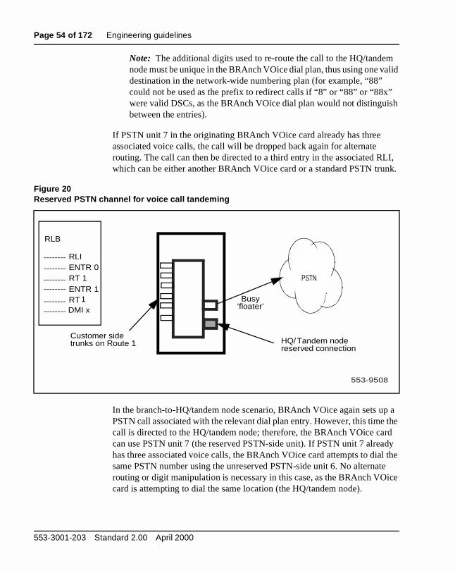
Engineer voice callsWhen BRAnch VOice attempts to deliver voice calls and experiences congestion, the calls are dropped back to the Meridian 1 system with a cof “no channel/circuit available.” The call is then directed to the next entrythe RLI, which can be a PSTN route or another BRAnch VOice card.
In the case where HQ reservation is employed and a branch-to-branch ccannot be completed directly, the BRAnch VOice card and RLI associatewith the dialed number can be set up to direct the call via the HQ/tandemnode.
Figure 21 shows a typical branch-to-branch scenario, where a user dialsnumber associated with a remote branch. The call is directed to the first ein the associated RLI (ENTR 0), which is the BRAnch VOice customer-sroute. The relevant BRAnch VOice dial plan entry translates the dialed number to a PSTN number and normally initiates a PSTN call using unit(the unreserved PSTN-side unit). However if this call cannot be completbecause a PSTN call to another branch already exists on this unit, or if 3 vcalls to the destination branch already exist on this unit, or if congestionencountered—the destination BRAnch VOice unit 6 can be busy—the cadropped back into the switch for alternate routing.
The call is then directed to the second entry in the associated RLI (ENTRwhich is the same route, but with a DMI to add leading digits to the dialenumber. The new number must have a dial plan entry on the BRAnch VOcard associated with the leading digits added by the digit manipulation, effectively causing the dialed number to translate to the HQ/tandem nodPSTN number. The leading digits added by the digit manipulation in ENTare configured to be deleted in the dial plan entry, thus presenting the codialed number to the HQ/tandem node. The HQ/tandem node, in turn, rothe call to the final destination across the network.
Meridian BRAnch VOice 1.0 Description, Installation, and Operation
Page 54 of 172 Engineering guidelines
alid
sh
LI, nk.
p a the rd dy l the te ice
Note: The additional digits used to re-route the call to the HQ/tandemnode must be unique in the BRAnch VOice dial plan, thus using one vdestination in the network-wide numbering plan (for example, “88” could not be used as the prefix to redirect calls if “8” or “88” or “88x” were valid DSCs, as the BRAnch VOice dial plan would not distinguibetween the entries).
If PSTN unit 7 in the originating BRAnch VOice card already has three associated voice calls, the call will be dropped back again for alternate routing. The call can then be directed to a third entry in the associated Rwhich can be either another BRAnch VOice card or a standard PSTN tru
In the branch-to-HQ/tandem node scenario, BRAnch VOice again sets uPSTN call associated with the relevant dial plan entry. However, this timecall is directed to the HQ/tandem node; therefore, the BRAnch VOice cacan use PSTN unit 7 (the reserved PSTN-side unit). If PSTN unit 7 alreahas three associated voice calls, the BRAnch VOice card attempts to diasame PSTN number using the unreserved PSTN-side unit 6. No alternarouting or digit manipulation is necessary in this case, as the BRAnch VOcard is attempting to dial the same location (the HQ/tandem node).
Figure 20Reserved PSTN channel for voice call tandeming
RLB
RLIENTR 0RT 1ENTR 1RT 1DMI x
PSTN
Busy‘floater’
HQ/Tandem nodereserved connection
Customer sidetrunks on Route 1
553-9508
----------------
--------------------------------
553-3001-203 Standard 2.00 April 2000
Engineering guidelines Page 55 of 172
n the
e call A
rnate 21.
ice N
to ll to nch oint
the CA
d in
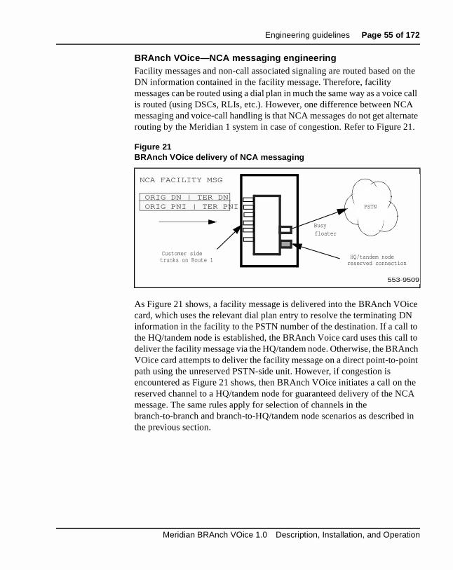
BRAnch VOice—NCA messaging engineeringFacility messages and non-call associated signaling are routed based oDN information contained in the facility message. Therefore, facility messages can be routed using a dial plan in much the same way as a voicis routed (using DSCs, RLIs, etc.). However, one difference between NCmessaging and voice-call handling is that NCA messages do not get alterouting by the Meridian 1 system in case of congestion. Refer to Figure
As Figure 21 shows, a facility message is delivered into the BRAnch VOcard, which uses the relevant dial plan entry to resolve the terminating Dinformation in the facility to the PSTN number of the destination. If a callthe HQ/tandem node is established, the BRAnch Voice card uses this cadeliver the facility message via the HQ/tandem node. Otherwise, the BRAVOice card attempts to deliver the facility message on a direct point-to-ppath using the unreserved PSTN-side unit. However, if congestion is encountered as Figure 21 shows, then BRAnch VOice initiates a call onreserved channel to a HQ/tandem node for guaranteed delivery of the Nmessage. The same rules apply for selection of channels in the branch-to-branch and branch-to-HQ/tandem node scenarios as describethe previous section.
Figure 21BRAnch VOice delivery of NCA messaging
PSTN
Busyfloater
reserved connection
Customer sidetrunks on Route 1
ORIG DN | TER DN ORIG PNI | TER PNI
NCA FACILITY MSG
553-9509
HQ/tandem node
Meridian BRAnch VOice 1.0 Description, Installation, and Operation
Page 56 of 172 Engineering guidelines
h dem h is
ivery h the
ID
has o he d 2
te 2.
CA
ave ribes tee le, as ire
Engineer multiple BRAnch VOice cards in a branchIf a branch requires more than one BRAnch VOice card, a single BRAncVOice card can be configured to have a channel reserved for the HQ/tannode to route all non-call associated traffic for that branch. This approacrecommended to ensure delivery of NCA messages associated with centralized services, such as NMS, but does not necessarily apply to delof messages associated with the NRAG feature, which are associated witroute over which the voice calls are being made.
For incoming PSTN calls from the HQ, the PSTN call is directed to the reserved channel using the DID number and route associated with the reserved channel. Incoming voice calls from the HQ/tandem node dial a Dnumber reserved for cards with the HQ flag configured. The call is then directed to route 1, the reserved channel, as Figure 20 shows. If route 1reached the three call limit, then the HQ incoming PSTN calls overflow tPSTN-side trunk members associated with route 2. This is supported if tRLI that the incoming HQ/tandem node call terminates on has route 1 anas ENTR 0 and ENTR 1, respectively.
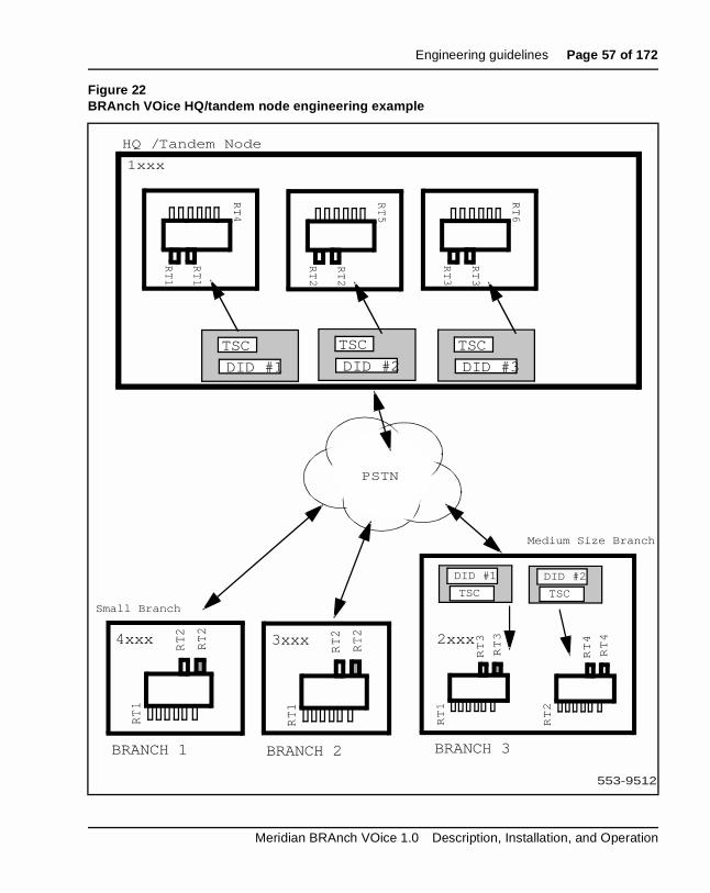
If an incoming call is from another branch, then the incoming DID #2 is reserved only for inter-branch traffic. DID #2 should never appear in the dialplan of a HQ/tandem node BRAnch VOice. The incoming call from the other branch routes to PSTN-side trunk units/channels associated only with rouInter-branch traffic must never terminate on route 1 as Figure 22 shows.
Engineer HQ/tandem nodesAs stated previously, to guarantee delivery of NCA messaging, the HQ/tandem node(s) should have enough resources available to deliver Nmessaging to any branch in the network.
To guarantee connectivity to each branch, each HQ/tandem node must hat least one BRAnch VOice card for each branch node.This section desca configuration which guarantees delivery of NCA messaging. To guaranvoice call delivery from branch nodes with multiple BRAnch VOice cardsthen additional cards must be added to the HQ/tandem node. For exampFigure 22 shows, the medium branch with two BRAnch VOice cards requanother card in the HQ/tandem node to guarantee voice connectivity.
Figure 22 shows a typical HQ/tandem node and a number of small and medium-sized branches.
553-3001-203 Standard 2.00 April 2000
Engineering guidelines Page 57 of 172
Figure 22BRAnch VOice HQ/tandem node engineering example
PSTN
RT4
RT1
RT1
RT2
RT2
RT1
RT5
RT2
RT2
RT6
RT3
RT3
RT3
RT3
RT1
RT4
RT4
RT2
HQ / Tandem Node
BRANCH 1 BRANCH 2 BRANCH 3
4xxx 2xxx
1xxx
DID #1
TSC
DID #2
TSC
DID #3
TSC
3xxx
RT2
RT2
RT1
DID #1
TSCTSC
DID #2
TSCTSC
Medium Size Branch
Small Branch
553-9512
Meridian BRAnch VOice 1.0 Description, Installation, and Operation

Page 58 of 172 Engineering guidelines
h None tion.
r a the
ch dem lan
sed ice in rate
ch nd t
ses
elay s
rk e use
HQ/tandem node BRAnch VOice cards One BRAnch VOice card is configured in the HQ/tandem node per brancnode. Each of the PSTN-side units can be configured on the same route. of the BRAnch VOice cards in the HQ/tandem node use channel reservaEach of the BRAnch VOice cards must use a separate route for the customer-side trunks. In this way, voice and NCA messaging destined foparticular branch use the correct BRAnch VOice. Each BRAnch VOice in tandem node is dedicated for connectivity to a particular branch.
To guarantee delivery of centralized services and voice call access at eabranch, the routes used for the customer-side trunks in each of the HQ/tannode BRAnch VOice cards must not appear in the same RLI. The dialing pin the HQ/tandem node BRAnch VOice cards must dial the DID number ufor accessing the reserved channel at each branch. As each BRAnch VOthe tandem node is dedicated to a branch, incoming calls must dial sepaDID numbers.
Medium-sIzed branch node BRAnch VOice cardsThis branch has more than one BRAnch VOice card. The second BRAnVOice card cannot access the HQ/tandem node for voice calls. The secoBRAnch VOice should only be used for inter-branch traffic and should nohave the DID number of a HQ/tandem node in its dial plan.
Minimize multiple call hopsTo transport multiple voice calls across the PSTN call, BRAnch VOice uthe G.729A voice codec with 20 ms packet size to achieve bandwidth reduction. Voice compression introduces some loss of information and din the voice signal, leading to eventual degradation of voice quality acrosmultiple hops. To minimize this effect, it is recommended that the netwotopology should be engineered to allow no more than two BRAnch VOichops, or one BRAnch VOice hop to a centralized voice mail system, becaof the voice compression employed by mail systems for storage capacityreduction.
553-3001-203 Standard 2.00 April 2000

Engineering guidelines Page 59 of 172
the ted, an , the k
t
Operational MeasurementsBRAnch VOice stores Operational Measurements (OMs) to indicate theutilization level of each PPP pipe. Various statistics are provided, such asnumber of incoming and outgoing PSTN calls attempted/completed/rejecthe total time spent on voice calls, the total time for PSTN calls (which cbe used to measure the cost effectiveness of the BRAnch VOice solution)number of incoming and outgoing NCA messages, the number of fallbaccalls, and the number of fax calls.
Advice of Charge (AOC) is generated for the ISDN bearer trunks and nospecifically for the BRAnch VOice ISL trunks. Billing for BRAnch VOice calls involves consolidation of CDR records associated with a BRAnch VOice (EXUT) call and the associated ISDN bearer call.
Meridian BRAnch VOice 1.0 Description, Installation, and Operation

Page 60 of 172 Engineering guidelines
553-3001-203 Standard 2.00 April 2000
Page 61 of 172
142
ice
ch
ied
ich ch
Installation and confi gurationThis chapter explains how to install and configure a Meridian BRAnch VO1.0 card in a Meridian 1 branch node and an HQ/tandem node.
Before you be ginCheck the following:
• the management LAN is in position if you plan to connect the BRAnVOice card to the LAN
Note: It is not mandatory to connect the BRAnch VOice card to the management LAN. Configuration and maintenance can also be carrout via a serial connection, and loadware upgrade via the faceplate PCMCIA slot.
• NT6D80, an MSDL card (in Option 51C-81C)
• you have a SDI/DCH card (NTAK02BB or later) in an Option 11C
• read and apply “Engineering guidelines” on page 37
You must provide one serial cable per BRAnch VOice card. An Ethernetcable is only required if you are connecting to the management LAN, whis not mandatory on the BRAnch VOice card. You must match the BRAnVOice card configuration to your management LAN and your Meridian 1dialing plan.
• The minimum X11 software release should be 22.
• The installer must ensure that the relevant patch is installed. Pleaseconsult the Product Bulletin for more details.
Meridian BRAnch VOice 1.0 Description, Installation, and Operation

Page 62 of 172 Installation and configuration
Installation summar yTable 5 summarizes how to install and configure a BRAnch VOice installation and configuration:
Table 5Summary of BRAnch VOice card installation and configuration
Step Page
Installation preparation page 63
• Inspect the package contents page 63
• Take inventory page 63
• Choose the card slot page 63
• Install and connect the D-channel PCMCIA interface card page 66
BRAnch VOice card installation page 68
BRAnch VOice card cabling page 69
• Connect the I/O panel cable page 69
• Connect the serial maintenance port (P2) to a terminal page 69
• Connect the LAN port (P3) to the management LAN page 70
• Connect the D-channel interface port (P4) to the MSDL or SDI/DCH card page 70
X11 system configuration page 74
• Configure D-channels in Overlay 17 page 75
• Configure trunk routes in Overlay 16 page 76
• Configure trunks in Overlay 14 page 78
• Configure the dialing plan with Overlays 86, 87, and 90 page 79
• Configure Incoming Digit Conversion (IDC) page 84
553-3001-203 Standard 2.00 April 2000

Installation and configuration Page 63 of 172
and rd
n you uter
fore
ard
an
ans, in ow he
nel ble
Installation preparationThe preparation includes the removal of the contents from the package inspecting the components. You must take inventory and choose the caslots where you plan to install the BRAnch VOice card.
Inspect the package contentsRemove the contents from the package and inspect the equipment. Wheremove the contents, follow general precautions recommended by compand telephone equipment manufacturers:
• Remove items that generate static charge from the installation site.
• Ground your body before handling any equipment.
• Remove equipment carefully from its packaging.
• Inspect the equipment for faults or damage.
Take inventoryAfter you unpack and inspect, check that all the equipment is at the site bethe installation begins. Check the equipment you received against the shipping documents. Make sure you received one D-channel PCMCIA cfor each BRAnch VOice card.
Choose the card slotYou can install a BRAnch VOice card in an appropriate IPE card slot in IPE module. You cannot use the Peripheral Controller card slot marked “Cont.” Each BRAnch VOice card fills two slots; however, the BRAnch VOice card connects to the backplane only in the left-hand slot. This mein an IPE shelf, you can connect a BRAnch VOice card to the backplaneslots 0-6 and 8-15. Refer to Table 6 for more details. It is important to knwhich card slot you connected a BRAnch VOice card to when enabling tcard.
Because BRAnch VOice requires access to all tip/ring pairs at the I/O paconnector, you must install the BRAnch VOice card into one of the availaslots as listed in Table 6.
Meridian BRAnch VOice 1.0 Description, Installation, and Operation

Page 64 of 172 Installation and configuration
e rial
st
rm
E
Regardless of whether you plan to network the BRAnch VOice card to thmanagement LAN, you must wire the I/O panel correctly to access the seports. (The serial ports exit on the high tip/ring pairs.) Therefore, you muinstall the BRAnch VOice card into one of the available slots that Table 6lists.
In Option 11C, you can install the BRAnch VOice card in any card slot fo1 to 10 in the main cabinet or the expansion cabinet.
In NT8D37BA and NT8D37EC (and later vintage) IPE Modules, all 16 IPcard slots support 24-pair cable connections. Table 7 shows the cable connections from the backplane to the inside of the I/O panel.
CAUTIONBefore installing the BRAnch VOice card, make sure there are no existing connections at the I/O panel connector associated with that BRAnch VOice card. Cross-connecting wires that transmit a ringing voltage can damage the BRAnch VOice card.
Table 6Card slots available for BRAnch VOice connection to the LAN
Meridian 1 module Acceptable card slots
NT8D37BA/EC IPE modules 0-6 and 8-15
NT8D37AA/DC IPE modules Slots 0, 4, 8, and 12
553-3001-203 Standard 2.00 April 2000

Installation and configuration Page 65 of 172
Table 7NT8D37 cable connections
Backplane slots-shroud
rows
I/O panel/cable designation
L0-1,2,3 A
L1-1,2,3 B
L2-1,2,3 C
L3-1,2,3 D
L4-1,2,3 E
L5-1,2,3 F
L6-1,2,3 G
L7-1,2,3 H
L8-1,2,3 K
L9-1,2,3 L
L10-1,2,3 M
L11-1,2,3 N
L12-1,2,3 R
L13-1,2,3 S
L14-1,2,3 T
L15,1,2,3 U
Meridian BRAnch VOice 1.0 Description, Installation, and Operation

Page 66 of 172 Installation and configuration
tion.
el .) ust ng
Table 8 describes the NT8D37 cable connections for 12-cable configura
Install and connect the D-channel PCMCIA interface cardCommunication between the BRAnch VOice card and the D-channel handlers is through the D-channel PCMCIA interface card. (The D-channhandler is the MSDL for large systems and the SDI/DCH for Option 11CBefore you can install the BRAnch VOice card into its selected slot, you minstall and connect the D-channel PCMCIA interface card. Do the followifor each BRAnch VOice card:
1 Insert the D-channel interface card in drive B: of the BRAnch VOice card. Drive B: is the PCMCIA slot on the side of the BRAnch VOice card. Refer to Figure 23 on page 67.
2 Connect Unit 0 of this card to the header (J14) on the side of the BRAnch VOice card using the NTCW84EA pigtail cable.
Table 8NT8D37 cable connections for 12-cable configuration
Backplane slots-shroud rowsI/O panel/cable
designation
L0-1 L0-2 L0-3 A
L1-1 L1-2 L1-3 B
L2-2 L3-1 L3-2 C
L4-1 L4-2 L4-3 E
L5-1 L5-2 L5-3 F
L6-1 L6-2 L6-3 G
L8-1 L8-2 L8-3 K
L9-1 L9-2 L10-1 L
L10-1 L11-2 L11-2 M
L12-1 L12-2 L12-3 R
L13-1 L13-2 L14-1 S
L14-2 L15-1 L15-2 T
553-3001-203 Standard 2.00 April 2000

Installation and configuration Page 67 of 172
Note 1: This connection routes the RS-422 signals to and from the D-channel unit (P4) on the I/O panel cable.
Note 2: NTWE07AA is the programmed version of NTMF93. When programmed, a small NTWE07AA label is applied to the underside of the PCMCIA card, but the NTMF93 label is not removed.
Figure 23Connection of the PCMCIA card and pigtail cable (NTCW84EA)
NTCW84EApigtail cable
Pin headerJ14
BRVO
8-portdaughterboard
553-9100
PCMCIANTMF93(NTWE07AA)
Unit 0
Meridian BRAnch VOice 1.0 Description, Installation, and Operation

Page 68 of 172 Installation and configuration
BRAnch VOice card installationTo install BRAnch VOice cards into an IPE shelf or into an Option 11C, follow these steps:
1 Identify the card slot(s) selected for BRAnch VOice card(s).
2 Pull the top and bottom latches away from the BRAnch VOice faceplate.
3 Insert the BRAnch VOice card into the card guides and carefully push it until it makes contact with the I/O backplane connector.
4 Push the top and the bottom latches towards the faceplate to lock the BRAnch VOice card into the module or cabinet.
5 Observe the faceplate maintenance display for the start-up self-test results and status messages, which appear in the form “T:xx ”. A display of the type “F:xx ” indicates a failure. Some failures indicate that you must replace the card. Refer to “Display codes” on page 147 for a complete listing and description of the codes.
Note 1: Once the BRAnch VOice card has successfully booted up, the faceplate alphanumeric display continually cycles through the following codes: EV0x, FV0x, EP0x, FP0x, and BRVO. Refer to Table 22, “BRAnch VOice alarms,” on page 152 for an explanation of these codes.
Note 2: “F:10” appears temporarily on the display, which indicates a security device test failure. However, because Meridian BRAnch VOice 1.0 does not use a security device, you can ignore this message.
6 Complete the cabling for the BRAnch VOice card. Refer to “BRAnch VOice card cabling” on page 69 for detailed instructions.
7 Completely configure the BRAnch VOice card in the X11 system software, if you have not done so. Refer to “X11 system configuration” on page 74 for detailed instructions.
8 Configure the BRAnch VOice card through the CLI. Refer to “BRAnch VOice configuration description” on page 88 for more details.
9 To enable the BRAnch VOice card, load the Network and PE Diagnostic program, LD 32, into the system memory through the system terminal. Execute the ENLC l s c command, where l is the loop, s is the module or shelf, and c is the card to enable.
553-3001-203 Standard 2.00 April 2000

Installation and configuration Page 69 of 172
e
ice
al)
ge
s.
erial
) at
10 Enable the D-channel for the BRAnch VOice card. The D-channel should be enabled. Execute the ENL DCH x command, where x is the D-channel number.
11 Repeat steps 1 through 6 for each additional BRAnch VOice card in Overlay 96
BRAnch VOice card cablin gAfter you have installed each BRAnch VOice card, you must perform thecabling of each card to complete the installation.
Connect the I/O panel cableConnect the 50-pin connector of the I/O panel cable (NTCW84HB) to th50-pin connector on the I/O panel. The other end of the I/O panel cable provides four ports for the following connections:
• A serial port (marked P2) for maintenance access to the BRAnch VOcard (optional)
• A LAN port (marked P3) for remote access and management (option
• A D-channel interface port (marked P4) to connect to the MSDL (larsystems) or the SDI/DCH (Option 11C) card (required)
• A serial port (marked P5) is reserved for call details in future release
The following sections describe the connections of these four ports.
Connect the serial maintenance port (P2) to a terminalFor permanent serial access to the BRAnch VOice card, connect a maintenance terminal to the serial port (P2) of the I/O panel cable. For temporary access, you can use the NTAG81CA cable to connect to the sport through the faceplate 8-pin connector.
Note: You cannot have devices on faceplate and I/O panel cable (P2the same time.
Meridian BRAnch VOice 1.0 Description, Installation, and Operation

Page 70 of 172 Installation and configuration
you al
ment 3)
k
the 4
Make sure the maintenance terminal has the following settings:
• 9600 bps• 8 data bits• 1 stop bit• no parity• no flow control
Permanent serial connection of a terminal is optional and not necessary ifconnect the BRAnch VOice to your management LAN. However, for initiEthernet configuration of the BRAnch VOice card, you must connect a terminal to the serial port. Ethernet configuration includes entering the BRAnch VOice card’s IP address, gateway address, and subnet mask.
Connect the LAN port (P3) to the management LANThis 10-BaseT Ethernet port (P3) enables connection of remote manageand alarm monitoring equipment. The female adapter on the LAN port (Pallows you to use a standard Ethernet cable to connect directly to the equipment or into the local network. You can connect to the local networthrough a hub or LAN socket. The delivery of the LAN signals to the I/O panel requires the cabling of all tip/ring pairs. If you require connection to LAN, install the BRAnch VOice card into any slot that Table 6 on page 6lists. See “BRAnch VOice IP Address configuration” on page 97 for information on entering IP addresses for menu options.
Connect the D-channel interface port (P4) to the MSDL or SDI/DCH card
To connect the D-channel interface port (P4) to the MSDL card (large systems), do the following:
1 Attach the D-channel interface (P4) to the male connector of the NTMF04BA cable.
2 Attach the female connector of the NTMF04BA cable to the male connector of the NTND26 cable.
3 Attach the female connector of the NTND26 cable to the selected port on the MSDL faceplate. Refer to Figure 24.
553-3001-203 Standard 2.00 April 2000

Installation and configuration Page 71 of 172
Figure 24BRAnch VOice cabling setup for large systems (Options 51C-81C)
BRAnch VOice slotNTCW84HB
to NTND26
RJ-45/Ethernet
To LAN/hub
ManagementLAN (P3)
D-channel (P4)
Serial Maintenance (P2)
Reserved (P5)
NTMF04BA
NTND26
I/O Panel
MS
DL
553-9101
Meridian BRAnch VOice 1.0 Description, Installation, and Operation

Page 72 of 172 Installation and configuration
To connect the D-channel interface port (P4) to the SDI/DCH card (Option 11C), do the following:
1 Attach the D-channel interface (P4) to the male connector of either the NTWE04AC (10’ inter-cabinet) or the NTWE04AD (1’ intra-cabinet) cable.
2 Attach the female connector of the NTWE04AC or NTWE04AD cable to Unit 1 of the NTAK19FB I/O panel cable of the SDI/DCH card. Refer to Figure 25 on page 73.
553-3001-203 Standard 2.00 April 2000

Installation and configuration Page 73 of 172
Figure 25BRAnch VOice cabling setup for Option 11C
BRAnch VOice slot NTCW84HB
to NTAK19FB
RJ-45/Ethernet
To LAN/hub
ManagementLAN (P3)
D-channel (P4)
Serial Maintenance (P2)
Reserved P5
NTWE04AC/AD
SDI/DCH slot
NTAK19FB
Unit 1
I/O Panel
I/O Panel
553-9102
Meridian BRAnch VOice 1.0 Description, Installation, and Operation

Page 74 of 172 Installation and configuration
h
the
n.
in as
is
X11 system confi gurationIn the X11 system software, you must configure the following for BRAncVOice:
• D-channels for the Meridian 1’s ISL links to BRAnch VOice (one D-channel per BRAnch VOice card)
• The ISL D-channel connection for each BRAnch VOice card
• Two or three TIE routes for each BRAnch VOice card (two if the two PSTN-side trunks route to the same location; three if two PSTN-side trunks route to different locations)
• Six BRAnch VOice trunks with ISL for voice (customer-side) calls
• Two BRAnch Voice trunks for data (PSTN-side) calls
• Dialing plan information within the private network
• Enable card using LD 32 and enable D-channel using LD 96
The customer must configure BRAnch VOice as an MCDN ISL connectioBRAnch VOice can access the PSTN using either BRI or PRI ISDN hardware. The PSTN-side trunks must support data calls (DSEL = VODLD 16). The customer must configure the BRAnch VOice ISL connectioninterface type SL1 (MCDN).
The following sections detail the X11 system software configuration thatnecessary for BRAnch VOice to function.
Overlay 15Make sure that DITI = YES in the customer data block, NET_DATA. TheBRAnch VOice connection to the PSTN is a DID to TIE connection.
553-3001-203 Standard 2.00 April 2000

Installation and configuration Page 75 of 172
rd.
Configure D-channels in Overlay 17The customer must configure one D-channel for each BRAnch VOice caTo configure D-channels for the Meridian 1’s ISL (ISDN Serial Link) linksto BRAnch VOice, load Overlay 17 using the system terminal. Enter theappropriate responses to the prompts (see Table 9).
Table 9Configure D-channels (LD 17)
Prompt Response Prompt description
REQ NEW
TYPE ADAN Type of data block
-ADAN NEW DCH x Action device and number (x is the D-channel number, from 0 to 63)
-CTYPE MSDL
DCHI
Meridian 1 card type
The response is different for Option 11C
-GRP 0-4 Network group number for Option 81
-DNUM 0-15 Device number for I/O ports
-PORT 0-3 Port number for MSDL or SDI/CDH card
-USR ISLD User
-IFC SL1 Interface type for D-channel (MSDN)
--ISLM 8 Integrated services signalling link maximum
-CLOK INT1 Internal clock
-SIDE USR (BRAnch VOice is network side)
-RCAP MWI, NAC, ND2, TAT
Remote capabilities
-NASA YES Allow Network Attendant Services
Note 1: If you use the external clock controller, set CLOK = EXT (default).
Meridian BRAnch VOice 1.0 Description, Installation, and Operation
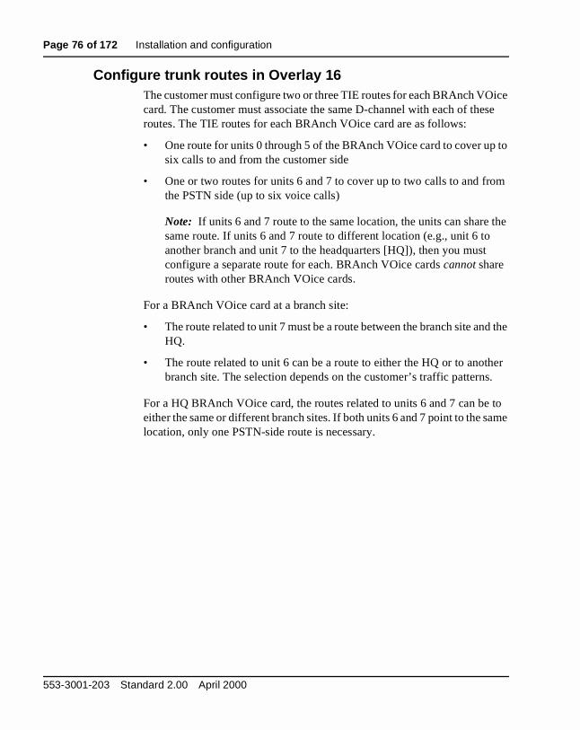
Page 76 of 172 Installation and configuration
ice se
to
m
the
d the
her .
to ame
Configure trunk routes in Overlay 16The customer must configure two or three TIE routes for each BRAnch VOcard. The customer must associate the same D-channel with each of theroutes. The TIE routes for each BRAnch VOice card are as follows:
• One route for units 0 through 5 of the BRAnch VOice card to cover upsix calls to and from the customer side
• One or two routes for units 6 and 7 to cover up to two calls to and frothe PSTN side (up to six voice calls)
Note: If units 6 and 7 route to the same location, the units can sharesame route. If units 6 and 7 route to different location (e.g., unit 6 to another branch and unit 7 to the headquarters [HQ]), then you must configure a separate route for each. BRAnch VOice cards cannot share routes with other BRAnch VOice cards.
For a BRAnch VOice card at a branch site:
• The route related to unit 7 must be a route between the branch site anHQ.
• The route related to unit 6 can be a route to either the HQ or to anotbranch site. The selection depends on the customer’s traffic patterns
For a HQ BRAnch VOice card, the routes related to units 6 and 7 can beeither the same or different branch sites. If both units 6 and 7 point to the slocation, only one PSTN-side route is necessary.
553-3001-203 Standard 2.00 April 2000

Installation and configuration Page 77 of 172
ter
To configure a TIE route, load Overlay 16 using the system terminal. Enthe appropriate responses to the prompts that Table 10 shows.Table 10Define a TIE route for accessing BRAnch VOice trunks (LD 16)
Prompt Response Description
REQ NEW/CHG Define new or change existing configuration
TYPE RDB Route data block
CUST 0-99 Customer number
ROUT 0-511 Route number
TKTP TIE BRAnch VOice trunk type
DTRK NO Digital trunk route
ISDN YES Integrated Services Digital Network
-MODE ISLD Mode of operation
-DCH x D-channel number for the BRAnch VOice card, which you defined in Overlay 17 at the ADAN prompt
-IFC SL1 Interface type (SL1 for MCDN)
ICOG IAO Incoming and outgoing trunk
Meridian BRAnch VOice 1.0 Description, Installation, and Operation
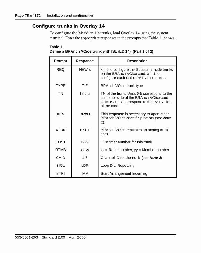
Page 78 of 172 Installation and configuration
ows.
Configure trunks in Overlay 14To configure the Meridian 1’s trunks, load Overlay 14 using the system terminal. Enter the appropriate responses to the prompts that Table 11 sh
Table 11Define a BRAnch VOice trunk with ISL (LD 14) (Part 1 of 2)
Prompt Response Description
REQ NEW x x = 6 to configure the 6 customer-side trunks on the BRAnch VOice card. x = 1 to configure each of the PSTN-side trunks
TYPE TIE BRAnch VOice trunk type
TN l s c u TN of the trunk. Units 0-5 correspond to the customer side of the BRAnch VOice card. Units 6 and 7 correspond to the PSTN side of the card.
DES BRVO This response is necessary to open other BRAnch VOice-specific prompts (see Note 1).
XTRK EXUT BRAnch VOice emulates an analog trunk card
CUST 0-99 Customer number for this trunk
RTMB xx yy xx = Route number, yy = Member number
CHID 1-8 Channel ID for the trunk (see Note 2 )
SIGL LDR Loop Dial Repeating
STRI IMM Start Arrangement Incoming
553-3001-203 Standard 2.00 April 2000

Installation and configuration Page 79 of 172
m rts ss
the
ting
S,
Configure the dialing plan with Overlays 86, 87, and 90BRAnch VOice supports the Electronic Switched Network (ESN) privatenetwork dialing plan with the Coordinated Dialing Plan (CDP), the UniforDialing Plan (UDP), and the Flexible Numbering Plan (FNP). FNP suppothe international dialing plan. The customer uses BARS and NARS accecodes, such as AC1 and AC2 to access different dialing plans.
Dialing plan setup for this feature requires ESN configuration on the Meridian 1 and the configuration of a dialing plan on the BRAnch VOice card. ESN configuration allows the Meridian 1 to route outgoing calls to BRAnch VOice card. BRAnch VOice’s dialing plan configuration allows BRAnch VOice call processing to do the following:
• translate the called party number to the PSTN number of the terminaBRAnch VOice node
• deliver calls to the destination over the PSTN
Use Overlays 86, 87, and 90 to configure the dialing plan (such as NARBARS, and CDP) within the private network.
STRO IMM Start Arrangement Outgoing
SUPN YES Answer and disconnect supervision required
CLS DIP/DTN Class of Service: Dial Pulse or Digitone
Note 1: You can print the trunk data block in LD 21 (LTM) to check that you configured the BRAnch VOice trunks correctly (DES = BRV$ in printout).
Note 2: Because each BRAnch VOice card has a separate D-channel connection, the maximum number of channel IDs per BRAnch VOice is eight. The channel ID increments by one for each BRAnch VOice trunk. The six customer-side trunks have channel IDs 1-6; the PSTN-side trunks have channel IDs 7 and 8.
Table 11Define a BRAnch VOice trunk with ISL (LD 14) (Part 2 of 2)
Prompt Response Description
Meridian BRAnch VOice 1.0 Description, Installation, and Operation

Page 80 of 172 Installation and configuration
l.
ESN confi gurationTo configure ESN information, load Overlay 86 using the system terminaEnter the appropriate responses to the prompts that Table 12 shows.Table 12Define ESN information (LD 86)
Prompt Response Description
REQ NEW
CUST 0-99 Customer number
FEAT ESN Electronic Switched Network
...
CDP YES Coordinated Dialing Plan
...
AC1 xx One- or two-digit NARS/BARS access code 1
AC2 yy One- or two-digit NARS access code 2
...
553-3001-203 Standard 2.00 April 2000

Installation and configuration Page 81 of 172
Route List Index confi gurationTo configure the Route List Index (RLI), do the following:
1 Configure an ESN block and a CDP or UDP number plan.
2 For each entry to an SL1 route in the Route List Data Block (RLB), enable Drop Back Busy (DBA) as Table 13 shows.
Table 13Route List Index (RLI) configuration with Drop Back Busy (LD 86)
Prompt Response Description
REQ NEW
CUST 0-99 Customer number
FEAT RLB Route List Data Block
RLI xx Route List Index
ENTR 0-63 Route List Entry
...
ROUT 0-511 Route number that refers to the BRAnch VOice trunk
SBOC RRA Reroute all for Step Back on Congestion
IDBB DBA Enable Drop Back Busy (Drop Back if All routes busy)
...
DMI 0 Do not use a Digit Manipulation table in the RLB entry for the BRAnch VOice ISL trunk route unless that RLB entry is being used specifically to redirect calls via the HQ reserved channel when the destination branch is unreachable directly. In this case, the Dial Plan table entry on the BRAnch VOice should be set up to delete the leading digit(s) inserted by this table. For ESN translations that are not used for NCA messages, digit manipulation can be defined on the BRAnch VOice card itself.
Meridian BRAnch VOice 1.0 Description, Installation, and Operation

Page 82 of 172 Installation and configuration
m ows.
.
Coordinated Dialin g Plan (CDP) confi gurationTo configure the CDP for BRAnch VOice, load Overlay 87 from the systeterminal. Enter the appropriate responses at the prompts that Table 14 sh
Note 1: You must configure a Trunk Steering Code (TSC) to route incoming calls to a PSTN-side trunk unit on the BRAnch VOice card
Note 2: If you use HQ PSTN Reservation in the branch, you must configure two TSCs for the card that reserves a channel for the HQ.
Table 14Configuration of the Coordinated Dialing Plan (LD 87)
Prompt Response Description
REQ NEW
CUST 0-99 Customer number
FEAT CDP Coordinated Dialing Plan
TYPE LSC, DSC, TSC
Type of steering code
...
RLB 5 Route List Entry that you created in LD 86
...
553-3001-203 Standard 2.00 April 2000

Installation and configuration Page 83 of 172
t the
Other dialin g plan confi gurationTo configure the other dialing plan information for BRAnch VOice, load Overlay 90 from the system terminal. Enter the appropriate responses aprompts that Table 15 shows.
Table 15Other dialing plan configuration (LD 90)
Prompt Response Description
REQ NEW
CUST 0-99 Customer number
FEAT NET
TRAN AC1, AC2, SUM
Access code 1, Access code 2, or Summary tables
TYPE HLOC, HNPA, LOC, NPA, NSCL, NXX, SPN
Type of data block
...
RLI 20 Route List Index that you created in LD 86
Meridian BRAnch VOice 1.0 Description, Installation, and Operation

Page 84 of 172 Installation and configuration
Configure Incoming Digit Conversion (IDC)
Note: For a diagram of the Incoming Digit Conversion (IDC) feature,refer to Figure 4 on page 21.
To configure the IDC feature, do the following:
1 Enable IDC in Overlay 15. See Table 16.
2 Create an IDC table in Overlay 49. See Table 17.
Table 16Enable IDC in the Customer Data Block (LD 15)
Prompt Response Description
REQ CHG
TYPE FCR
CUST 0-99 Customer number
-NFCR YES New Flexible Code Restriction
-MAXT 1-255 Maximum number of NFCR Trees
-IDCA YES Enable IDC
-DCMX 1-255 Maximum number of IDC tables
Table 17Create an IDC table (LD 49)
Prompt Response Description
REQ CHG
TYPE IDC
CUST 0-99 Customer number
DCNO 0-254 The IDC Tree number
IDGT 0-9999 0-9999
DN or DN range to convertWhat DN or DN range must convert to
553-3001-203 Standard 2.00 April 2000
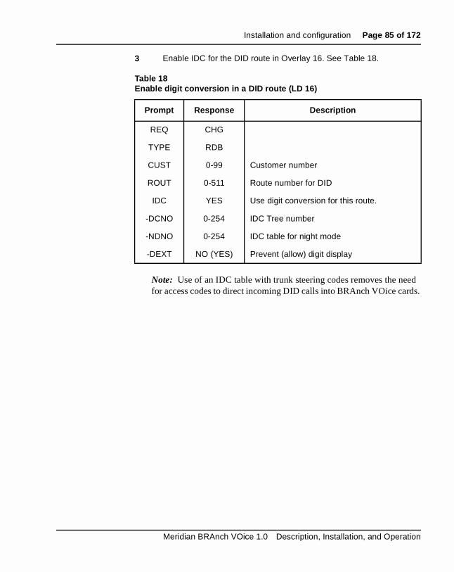
Installation and configuration Page 85 of 172
ed ds.
3 Enable IDC for the DID route in Overlay 16. See Table 18.
Note: Use of an IDC table with trunk steering codes removes the nefor access codes to direct incoming DID calls into BRAnch VOice car
Table 18Enable digit conversion in a DID route (LD 16)
Prompt Response Description
REQ CHG
TYPE RDB
CUST 0-99 Customer number
ROUT 0-511 Route number for DID
IDC YES Use digit conversion for this route.
-DCNO 0-254 IDC Tree number
-NDNO 0-254 IDC table for night mode
-DEXT NO (YES) Prevent (allow) digit display
Meridian BRAnch VOice 1.0 Description, Installation, and Operation

Page 86 of 172 Installation and configuration
553-3001-203 Standard 2.00 April 2000

Page 87 of 172
142
r
be
the
ese
rd
on all
bnet
Administration throu gh the CLIThis chapter describes how to access and perform operations and administration on the BRAnch VOice card. Administration of the BRAnchVOice card is through a Command Line Interface (CLI). Access the CLI through a VT100 terminal or a PC emulating a VT100 terminal. You canaccess the BRAnch VOice card either through a serial port on the card othrough Telnet. The first time you access the BRAnch VOice card must through a serial port.
Through a series of configuration menus, the BRAnch VOice CLI enablesconfiguration and viewing of all the BRAnch VOice configuration parameters.
Navigation hel pWhen you select q (“QUIT card configuration”) from any of the menus, the“Do you wish to Save Card Configuration? (y/n):” prompt appears. Enter y to save all configured items on the BRAnch VOice card to various files. Thitems will survive a card reboot or power-down. Enter n to lose any changes to the BRAnch VOice card that you did not save. The BRAnch VOice caloses these changes the next time you reboot or power-down the card.
Administration tasks summar yThere are five sets of parameters that you must configure for a BRAnchVOice card. These five configuration areas are:
• General card parameters (branch ID; card ID; HQ channel reservatiflag, PSTN number, and branch ID; private network ID; and End of CTimeout parameter)
• IP address information (card IP address, gateway IP address, and sumask)
Meridian BRAnch VOice 1.0 Description, Installation, and Operation

Page 88 of 172 Administration through the CLI
d
a
e port e fter ord
l
o card the
• Dialing plan information (Access Codes, Location Codes, Distance Steering Codes, and Trunk Steering Codes)
• SNMP trap information (SNMP Manager ID, IP Address, and subnetmask)
• BRAnch VOice software upgrade (from PCMCIA card or IP networkehost)
• Setting System time and date
You can use the CLI to upgrade the BRAnch VOice software, either fromPCMCIA card or from a networked host.
Access the CLIYou can access the menus to configure the card through the maintenancor through Telnet. When you configure the card initially, you must use thserial port, either through the faceplate or through the I/O panel cable. Athe card boots up, the login prompt appears. Enter the login ID and passwas the following shows:
VxWorks login: bravoadmin
Password: bravoadmin <not echoed>
You can change the user login and password. See “BRAnch VOice shelcommands” on page 141. After you log in, an easy menu system for configuring the card appears (see Figure 26).
BRAnch VOice confi guration descri ption Figure 26 shows the BRAnch VOice Main Configuration menu, which appears immediately after you log into a BRAnch VOice card.
At the Main Configuration menu, you have the following options:
• Enter 1 to access the General Configuration menu (also called BRAvVoice Card Parameters menu). There you configure the branch and IDs; the HQ channel reservation flag, PSTN number, and branch ID;private network ID; and the End of Call Timeout parameter.
553-3001-203 Standard 2.00 April 2000

Administration through the CLI Page 89 of 172
net ect
n You nch
rd
• Enter 2 to access the IP Address Configuration menu. There you canconfigure the card IP address, the gateway IP address, and the submask. You can revert to Non-Networked Settings if you do not connthe BRAnch VOice card to your network. See “BRAnch VOice IP Address configuration” on page 97.
• Enter 3 to access the SNMP Trap Configuration menu. There you caconfigure SNMP Managers to receive SNMP alarms and messages.can use this menu to disable/enable SNMP Traps/Alarms. See “BRAVOice SNMP Traps/Alarms Main configuration” on page 101.
• Enter 4 to access the Dial Plan Configuration menu. There you can configure UDP and CDP parameters. See “BRAnch VOice Dial Planconfiguration” on page 112.
• Enter 5 to access the Upgrade Card Software menu. There you can upgrade the BRAnch VOice card software, either from a PCMCIA caor from a networked host.
Figure 26BRAnch VOice Main Configuration menu
****************************************** * BRAVO CONFIGURATION MENU * ****************************************** * 1 .... General Configuration (MENU) * * 2 .... IP Address Configuration (MENU) * * 3 .... SNMP Trap Configuration (MENU) * * 4 .... Dial Plan Configuration (MENU) * * 5 .... Upgrade Card Software (MENU) * * 6 .... Display System Time * * 7 .... Change System Time * * 8 .... Save Card Configuration * * * * -------------------------------------- * * m --> Menu Redisplay * * q --> QUIT Card Configuration * ******************************************
Enter Option :
Meridian BRAnch VOice 1.0 Description, Installation, and Operation

Page 90 of 172 Administration through the CLI
re
ears
ill
• Enter 6 to display the system time and date and 7 to configure the system time and date.
• Enter 8 to save the current card configuration. You must do this befoexiting the CLI if you have changed any of the cards parameters.
• Enter m to refresh the menu display.
• Enter q to quit the card configuration and log out.
BRAnch VOice Card Parameters configurationFigure 27 shows the BRAnch VOice Card Parameters menu, which appafter you enter 1 at the Main Configuration menu. By entering 1, 2, 3, 4, 5, 6, 7, 8, or 9 at the “Enter Option:” prompt, the relevant option shown below wbe invoked.
Figure 27BRAnch VOice Card Parameters menu
****************************************** * BRAVO CARD PARAMETERS MENU * ****************************************** * 1 .... Display Current Card Parameters * * 2 .... Change Branch ID * * 3 .... Change Card ID * * 4 .... Change HQ Channel Reservation ** 5 .... Change HQ PSTN Number * * 6 .... Change HQ Branch ID * * 7 .... Change Private Network ID (PNI) * * 8 .... Change End of Call Timeout * * 9 .... Store Current Card Parameters * * * * -------------------------------------- * * m --> Menu Redisplay * * r --> Return to MAIN MENU * * q --> QUIT Card Configuration * ******************************************
Enter Option :
553-3001-203 Standard 2.00 April 2000

Administration through the CLI Page 91 of 172
ch ed to .e.
ber
ber )-15.
h
n a l (up
Branch ID and card IDThe combination of branch ID and card ID must be unique for every BRAnVOice card in a BRAnch VOice network. The branch ID is used to groupcards that are accessible via the same PSTN number. The card ID is usuniquely identify cards that are accessible via the same PSTN number icards with the same branch ID.
At the BRAnch VOice card parameters menu, you have the following options:
• Enter 1 to display the current card parameters.
• Enter 2 to change (or set) the branch ID. Use the branch ID to groupBRAnch VOice cards that are available through the same PSTN num(i.e., those that are part of the same branch). The branch ID range is0-(0)-1023.
• Enter 3 to change (or set) the card ID. Use the card ID to separate BRAnch VOice cards that are available through the same PSTN num(i.e., those that have the same branch ID). The card ID range is 0-(0
Note: The combination of branch ID and card ID must be distinct for each BRAnch VOice card in a BRAnch VOice network. If any BRAncVOice cards in a network have the same branch ID and card ID, theconflicting cards do not interwork. The conflict generates and alarm.
Headquarters Channel Reservation, PSTN Number, and branch IDTo support network features (non-call associated), a connection to the headquarters switch must always be available. Thus, at least one card iBRAnch VOice branch switch must reserve/dedicate one PSTN channeto three calls) for contact with the headquarters switch.
CAUTIONTake extreme care to ensure that no cards in the BRAnch VOice network have the same combination of Branch and card ID. If any twocards in the network have the same combination of Branch and card ID, the conflicting cards will not interwork.
Meridian BRAnch VOice 1.0 Description, Installation, and Operation

Page 92 of 172 Administration through the CLI
d. ese
ch ipe
the r
HQ
for
.
ing h as
e
fter nd
ers.
• To set the headquarters channel reservation flag settings, enter 0 if a PSTN channel is not reserved for contact with the headquarters switch(default).
• Enter 1 if a PSTN channel is reserved for contact with the headquartersswitch. If the headquarters channel reservation flag is set to 1, the PSTN number required to reach the headquarters switch must be configureThe branch ID of the headquarters switch must also be configured. Thare required in the delivery of non-call associated between two branswitches where the branch cannot be reached directly (the floating pis already connected to a different switch)
• Enter 5 to change (or set) the headquarters PSTN number. If you setHQ channel reservation flag to 1, you must configure the PSTN numbenecessary to reach the headquarters switch.
• Enter 6 to change (or set) the headquarters branch ID. If you set the channel reservation flag to 1, you must configure the branch ID of the headquarters switch.
Note: The headquarters PSTN number and branch ID are necessarythe delivery of non-call associated messages between two branch switches when a direct link between the two switches is not available
Private Network Identifier
• Enter 7 to change (or set) the Private Network Identifier (PNI). A PNIrefers to a switch customer number. It is necessary for the interworkbetween switches and the operation of supplementary services, sucNMS. BRAnch VOice transports the PNI in facility messages that transport these supplementary services. When interworking with a remote switch over an MCDN network, the CDB PNI is the PNI for thsource switch and the RDB PNI must match the PNI for the remote switch. The PNI range is 0-(0)-32700.
End of Call Timeout parameter
• Enter 8 to change (or set) the End of Call Timeout parameter. This parameter is the length of time that a PSTN call (pipe) remains open athe last BRAnch VOice call on the PSTN pipe has completed. The Eof Call Timeout range is 0-(6)-600 seconds.
• Enter 9 to store the current card parameters. You must do this beforeexiting the CLI if you have changed any of the general card paramet
553-3001-203 Standard 2.00 April 2000

Administration through the CLI Page 93 of 172
ot
n
• Enter m to refresh the menu display.
• Enter r to return to the Main Configuration menu.
• Enter q to quit the card configuration and log out.
Note: If you make changes to the branch ID and/or the card ID, rebothe card after you store the changes. Reboot the card before you allow call processing to occur on the card.
Card parameter confi guration (example trace )The following shows an example of setting the general card configuratioparameters:
****************************************** * BRAVO CONFIGURATION MENU * ****************************************** * 1 .... General Configuration (MENU) * * 2 .... IP Address Configuration (MENU) * * 3 .... SNMP Trap Configuration (MENU) * * 4 .... Dial Plan Configuration (MENU) * * 5 .... Upgrade Card Software (MENU) * * 6 .... Display System Time * * 7 .... Change System Time * * 8 .... Save Card Configuration * * * * -------------------------------------- * * m --> Menu Redisplay * * q --> QUIT Card Configuration * ****************************************** Enter Option : 1
****************************************** * BRAVO CARD PARAMETERS MENU * ****************************************** * 1 .... Display Current Card Parameters * * 2 .... Change Branch ID * * 3 .... Change Card ID * * 4 .... Change HQ Channel Reservation * * 5 .... Change HQ PSTN Number * * 6 .... Change HQ Branch ID * * 7 .... Change Private Network ID (PNI) * * 8 .... Change End of Call Timeout * * 9 .... Store Current Card Parameters * * * * -------------------------------------- *
Meridian BRAnch VOice 1.0 Description, Installation, and Operation

Page 94 of 172 Administration through the CLI
* m --> Menu Redisplay * * r --> Return to MAIN MENU * * q --> QUIT Card Configuration * ****************************************** Enter Option : 1
Current Card Parameters-----------------------Branch ID = 0Card ID = 0HQ Channel Reservation = 0HQ PSTN Number = 0HQ Branch ID = 0Private Network ID = 0End of Call Timeout = 0 secs
Enter Option : 2 Enter Branch ID : 1 Abort Request (y/n) : n WARNING: After changing Branch ID and/or Card ID the card MUST BE REBOOTED prior to attempting call processing. Enter Option : 3 Enter Card ID : 1 Abort Request (y/n) : n
553-3001-203 Standard 2.00 April 2000

Administration through the CLI Page 95 of 172
WARNING: After changing Branch ID and/or Card ID the card MUST BE REBOOTED prior to attempting call processing. Enter Option : 4 Enter Headquarters Channel Reservation (Reserve = 1) (Don’t Reserve = 0) : 1 Abort Request (y/n) : n Enter Option : 5 Enter Headquarters PSTN Number : 9091313216 Abort Request (y/n) : n Enter Option : 6 Enter Headquarters Branch ID : 4 Abort Request (y/n) : n Enter Option : 7 Enter Private Network ID : 1 Abort Request (y/n) : n Enter Option : 8 Enter End of Call PPP Timeout (in secs) : 10 Abort Request (y/n) : n Enter Option : 9 Card Parameters File (/C:/CONFIG/CONFIG1.INI) Saved ... Enter Option : 1 Current Card Parameters-----------------------Branch ID = 1Card ID = 1HQ Channel Reservation = 1HQ PSTN Number = 9091313216HQ Branch ID = 4Private Network ID = 1End of Call Timeout = 10 secs
Meridian BRAnch VOice 1.0 Description, Installation, and Operation
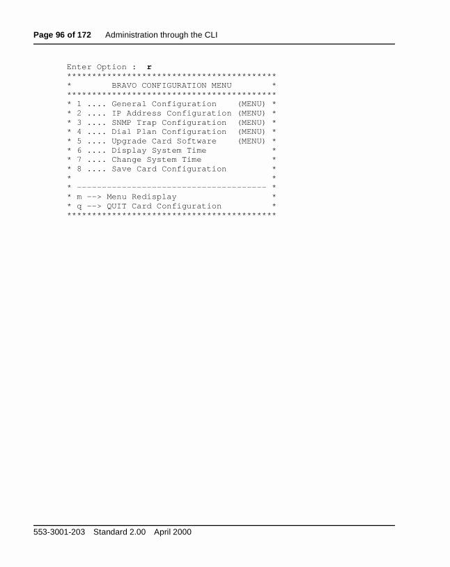
Page 96 of 172 Administration through the CLI
Enter Option : r****************************************** * BRAVO CONFIGURATION MENU * ****************************************** * 1 .... General Configuration (MENU) * * 2 .... IP Address Configuration (MENU) * * 3 .... SNMP Trap Configuration (MENU) * * 4 .... Dial Plan Configuration (MENU) * * 5 .... Upgrade Card Software (MENU) * * 6 .... Display System Time * * 7 .... Change System Time * * 8 .... Save Card Configuration * * * * -------------------------------------- * * m --> Menu Redisplay * * q --> QUIT Card Configuration * ******************************************
553-3001-203 Standard 2.00 April 2000

Administration through the CLI Page 97 of 172
fter
iate
st
BRAnch VOice IP Address configurationFigure 28 shows the BRAnch VOice IP Address menu, which appears ayou enter 2 at the Main Configuration menu. By entering 1, 2, 3, 4, or 9 at the “Enter Option:” prompt, the relevant option shown below is invoked.
The BRAnch VOice card can be IP networked by configuring the approprIP parameters (option 2).
• card IP Address
• gateway IP Address
• subnet mask
Once IP networked, telnet etc. can be used to access the card.
If the card does not need to be networked (the default settings), you muchoose option 3.
Figure 28BRAnch VOice IP Address menu
****************************************** * BRAVO IP ADDRESS MENU * ****************************************** * 1 .... Display Current IP Settings * * 2 .... Change IP Address Settings * * 3 .... Revert to Non-Networked Setting * * 4 .... Store Current IP Settings * * * * 9 .... Reboot Card * * * * -------------------------------------- * * m --> Menu Redisplay * * r --> Return to MAIN MENU * * q --> QUIT Card Configuration * ******************************************
Enter Option :
Meridian BRAnch VOice 1.0 Description, Installation, and Operation

Page 98 of 172 Administration through the CLI
is y
ow
e .
es
Note: After changing IP Address, the card should be rebooted (option9) immediately.
At the IP Address menu, you have the following options:
• Enter 1 to display the current IP Address Settings.
• Enter 2 to change (or set) the IP Address Settings. After you select thoption, the CLI prompts you to enter the card IP address, the gatewaaddress, and the subnet mask. Set these parameters correctly to allTelnet access to the BRAnch VOice card.
• Enter 3 to revert to the Non-Networked (default) Settings. Select thessettings if you do not connect the BRAnch VOice card to the network
• Enter 4 to store the current IP Settings. You must do this before you reboot the card to activate the new IP Settings.
• Enter 9 to reboot the BRAnch VOice card. You must do this for changto the IP address parameters to take affect.
• Enter m to refresh the menu display.
• Enter r to return to the Main Configuration menu.
• Enter q to quit the card configuration and log out.
553-3001-203 Standard 2.00 April 2000

Administration through the CLI Page 99 of 172
IP Address confi guration (example trace )The following shows an example of setting the IP Address parameters:
****************************************** * BRAVO CONFIGURATION MENU * ****************************************** * 1 .... General Configuration (MENU) * * 2 .... IP Address Configuration (MENU) * * 3 .... SNMP Trap Configuration (MENU) * * 4 .... Dial Plan Configuration (MENU) * * 5 .... Upgrade Card Software (MENU) * * 6 .... Display System Time * * 7 .... Change System Time * * 8 .... Save Card Configuration * * * * -------------------------------------- * * m --> Menu Redisplay * * q --> QUIT Card Configuration * ******************************************
Enter Option : 2 ****************************************** * BRAVO IP ADDRESS MENU * ****************************************** * 1 .... Display Current IP Settings * * 2 .... Change IP Address Settings * * 3 .... Revert to Non-Networked Setting * * 4 .... Store Current IP Settings * * * * 9 .... Reboot Card * * * * -------------------------------------- * * m --> Menu Redisplay * * r --> Return to MAIN MENU * * q --> QUIT Card Configuration * ******************************************
Enter Option : 3 Abort Revert to Non-Networked Setting Request (y/n) : nIP Configuration File (/C:/BOOTP/BOOTP.1) Saved ... IP Settings (below) will take effect on card reboot ...
Meridian BRAnch VOice 1.0 Description, Installation, and Operation

Page 100 of 172 Administration through the CLI
IP Settings-----------Card IP Address = 10.0.1.2Gateway IP Address = 10.0.1.1Subnet Mask = 255.255.255.240
Enter Option : 2 Change IP Address Settings--------------------------Enter Card IP Address : 47.85.2.71Enter Gateway IP Address : 47.85.0.1 Enter Subnet Mask : 255.255.240.0 Abort Request (y/n) : nIP Configuration File (/C:/BOOTP/BOOTP.1) Saved ... IP Settings (below) will take effect on card reboot ...
IP Settings-----------Card IP Address = 47.85.2.71Gateway IP Address = 47.85.0.1Subnet Mask = 255.255.240.0
Enter Option : 9 Reboot Card Option Chosen !!
Abort Reboot Request (y/n) : nCard is being rebooted ... Resetting card...
553-3001-203 Standard 2.00 April 2000
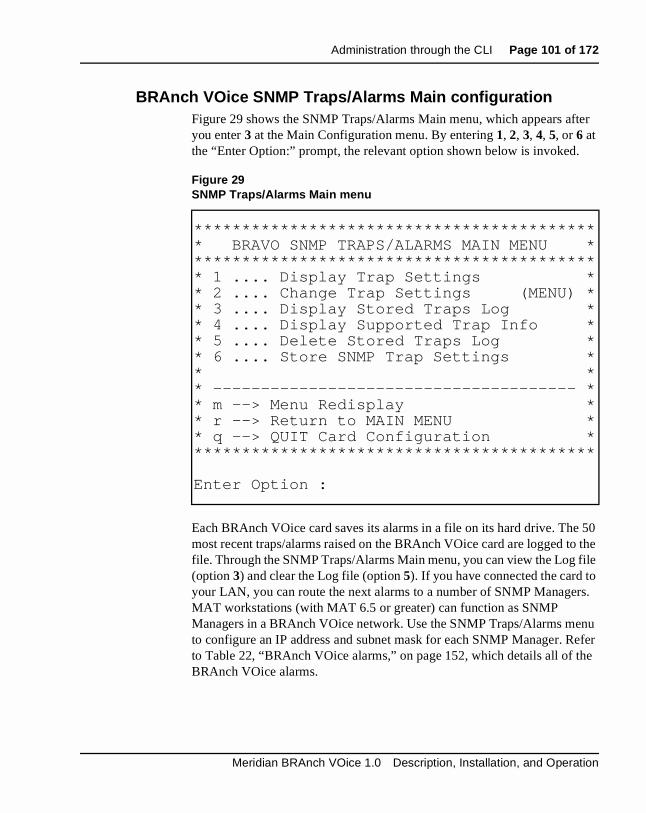
Administration through the CLI Page 101 of 172
ter
50 the
ile
rs.
nu efer e
BRAnch VOice SNMP Traps/Alarms Main configurationFigure 29 shows the SNMP Traps/Alarms Main menu, which appears afyou enter 3 at the Main Configuration menu. By entering 1, 2, 3, 4, 5, or 6 at the “Enter Option:” prompt, the relevant option shown below is invoked.
Each BRAnch VOice card saves its alarms in a file on its hard drive. Themost recent traps/alarms raised on the BRAnch VOice card are logged tofile. Through the SNMP Traps/Alarms Main menu, you can view the Log f(option 3) and clear the Log file (option 5). If you have connected the card toyour LAN, you can route the next alarms to a number of SNMP ManageMAT workstations (with MAT 6.5 or greater) can function as SNMP Managers in a BRAnch VOice network. Use the SNMP Traps/Alarms meto configure an IP address and subnet mask for each SNMP Manager. Rto Table 22, “BRAnch VOice alarms,” on page 152, which details all of thBRAnch VOice alarms.
Figure 29SNMP Traps/Alarms Main menu
****************************************** * BRAVO SNMP TRAPS/ALARMS MAIN MENU * ****************************************** * 1 .... Display Trap Settings * * 2 .... Change Trap Settings (MENU) * * 3 .... Display Stored Traps Log * * 4 .... Display Supported Trap Info * * 5 .... Delete Stored Traps Log * * 6 .... Store SNMP Trap Settings * * * * -------------------------------------- * * m --> Menu Redisplay * * r --> Return to MAIN MENU * * q --> QUIT Card Configuration * ******************************************
Enter Option :
Meridian BRAnch VOice 1.0 Description, Installation, and Operation

Page 102 of 172 Administration through the CLI
le:
the ble
rs. 5.
MP
If you choose option 2, the menu displays options that facilitate the configuration of SNMP Managers.
Note: MAT 6.5 (or greater) supports BRAnch VOice SNMP Traps/Alarms.
At the SNMP Trap Configuration menu, the following options are availab
• Enter 1 to display the current Trap Settings.
• Enter 2 to access the SNMP Traps/Alarms menu so you can changeTrap Settings. At the SNMP Traps/Alarms menu, you can enable/disathe Traps/Alarms. You can add, change, and delete SNMP ManageSee “BRAnch VOice SNMP Traps/Alarms configuration” on page 10
• Enter 3 to display the Traps/Alarms Log file on the card’s hard drive.
• Enter 4 to display the supported trap information.
• Enter 5 to clear the Traps/Alarms Log file from the card’s hard drive.
• Enter 6 to store the SNMP Trap Settings. If you have changed the SNTrap Settings, do this before you exit the SNMP Traps/Alarms Main menu.
• Enter m to refresh the menu display.
• Enter r to return to the Main Configuration menu.
• Enter q to quit the card configuration and log out.
553-3001-203 Standard 2.00 April 2000

Administration through the CLI Page 103 of 172
SNMP Main menu (example trace )The following shows an example of using the SNMP Traps/Alarms Mainmenu:****************************************** * BRAVO CONFIGURATION MENU * ****************************************** * 1 .... General Configuration (MENU) * * 2 .... IP Address Configuration (MENU) * * 3 .... SNMP Trap Configuration (MENU) * * 4 .... Dial Plan Configuration (MENU) * * 5 .... Upgrade Card Software (MENU) * * 6 .... Display System Time * * 7 .... Change System Time * * 8 .... Save Card Configuration * * * * -------------------------------------- * * m --> Menu Redisplay * * q --> QUIT Card Configuration * ******************************************
Enter Option : 3 ****************************************** * BRAVO SNMP TRAPS/ALARMS MAIN MENU * ****************************************** * 1 .... Display Trap Settings * * 2 .... Change Trap Settings (MENU) * * 3 .... Display Stored Traps Log * * 4 .... Display Supported Trap Info * * 5 .... Delete Stored Traps Log * * 6 .... Store SNMP Trap Settings * * * * -------------------------------------- * * m --> Menu Redisplay * * r --> Return to MAIN MENU * * q --> QUIT Card Configuration * ******************************************
Meridian BRAnch VOice 1.0 Description, Installation, and Operation

Page 104 of 172 Administration through the CLI
Enter Option : 1 SNMP Trap/Alarm Settings------------------------SNMP Traps are DISABLED
SNMP Manager 1 -> SNMP Manager 2 -> SNMP Manager 3 -> SNMP Manager 4 -> SNMP Manager 5 -> SNMP Manager 6 -> SNMP Manager 7 -> SNMP Manager 8 ->
Enter Option : 3
*****************************************************************BRV0104-------DSP Startup was successful.
Severity : ClearedStatus : ClearTimestamp : Date (09/07/1999) Time (12:11:10)*****************************************************************
*****************************************************************BRV0100-------Card Bootup was successful (Application started OK).
Severity : ClearedStatus : ClearTimestamp : Date (09/07/1999) Time (12:11:16)*****************************************************************
*****************************************************************BRV0451-------D-channel Card Removed. Associated channels to be busied out.D-Channel Number = 1
Severity : MajorStatus : SetTimestamp : Date (09/07/1999) Time (12:11:16)*****************************************************************
553-3001-203 Standard 2.00 April 2000
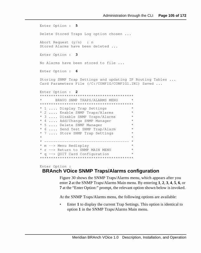
Administration through the CLI Page 105 of 172
u
d.
Enter Option : 5 Delete Stored Traps Log option chosen ...
Abort Request (y/n) : nStored Alarms have been deleted ...
Enter Option : 3 No Alarms have been stored to file ...
Enter Option : 6 Storing SNMP Trap Settings and updating IP Routing Tables ...Card Parameters File (/C:/CONFIG/CONFIG1.INI) Saved ...
Enter Option : 2****************************************** * BRAVO SNMP TRAPS/ALARMS MENU * ****************************************** * 1 .... Display Trap Settings * * 2 .... Enable SNMP Traps/Alarms * * 3 .... Disable SNMP Traps/Alarms * * 4 .... Add/Change SNMP Manager * * 5 .... Delete SNMP Manager * * 6 .... Send Test SNMP Trap/Alarm * * 7 .... Store SNMP Trap Settings * * * * -------------------------------------- * * m --> Menu Redisplay * * r --> Return to SNMP MAIN MENU * * q --> QUIT Card Configuration * ******************************************
Enter Option :
BRAnch VOice SNMP Traps/Alarms configurationFigure 30 shows the SNMP Traps/Alarms menu, which appears after yoenter 2 at the SNMP Traps/Alarms Main menu. By entering 1, 2, 3, 4, 5, 6, or 7 at the “Enter Option:” prompt, the relevant option shown below is invoke
At the SNMP Traps/Alarms menu, the following options are available:
• Enter 1 to display the current Trap Settings. This option is identical tooption 1 in the SNMP Traps/Alarms Main menu.
Meridian BRAnch VOice 1.0 Description, Installation, and Operation
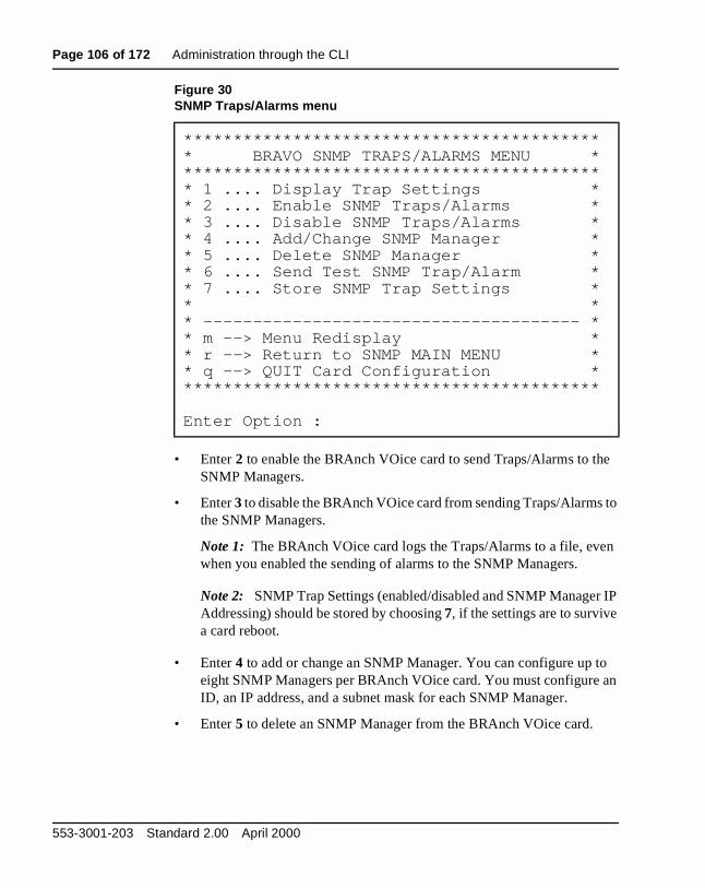
Page 106 of 172 Administration through the CLI
e
to
n
IP
o an
• Enter 2 to enable the BRAnch VOice card to send Traps/Alarms to thSNMP Managers.
• Enter 3 to disable the BRAnch VOice card from sending Traps/Alarmsthe SNMP Managers.
Note 1: The BRAnch VOice card logs the Traps/Alarms to a file, evewhen you enabled the sending of alarms to the SNMP Managers.
Note 2: SNMP Trap Settings (enabled/disabled and SNMP ManagerAddressing) should be stored by choosing 7, if the settings are to survivea card reboot.
• Enter 4 to add or change an SNMP Manager. You can configure up teight SNMP Managers per BRAnch VOice card. You must configureID, an IP address, and a subnet mask for each SNMP Manager.
• Enter 5 to delete an SNMP Manager from the BRAnch VOice card.
Figure 30SNMP Traps/Alarms menu
****************************************** * BRAVO SNMP TRAPS/ALARMS MENU * ****************************************** * 1 .... Display Trap Settings * * 2 .... Enable SNMP Traps/Alarms * * 3 .... Disable SNMP Traps/Alarms * * 4 .... Add/Change SNMP Manager * * 5 .... Delete SNMP Manager * * 6 .... Send Test SNMP Trap/Alarm * * 7 .... Store SNMP Trap Settings * * * * -------------------------------------- * * m --> Menu Redisplay * * r --> Return to SNMP MAIN MENU * * q --> QUIT Card Configuration * ******************************************
Enter Option :
553-3001-203 Standard 2.00 April 2000
Administration through the CLI Page 107 of 172
P
P .
Test alarm facilit y
• Enter 6 to send a test alarm (BRV9999) to all of the configured SNMManagers. For this test to work, you must first enable (option 2) the sending of alarms to SNMP Managers. Use this test to check the configuration of the SNMP Managers.
• Enter 7 store the SNMP Trap Settings. If you have changed the SNMTrap Settings, do this before you exit the SNMP Traps/Alarms menu
• Enter m to refresh the menu display.
• Enter r to return to the SNMP Traps/Alarms Main menu.
• Enter q to quit the card configuration and log out.
Meridian BRAnch VOice 1.0 Description, Installation, and Operation

Page 108 of 172 Administration through the CLI
SNMP Manager confi guration (example trace )The following shows an example of configuring SNMP Managers:
***************************************** * BRAVO SNMP TRAPS/ALARMS MAIN MENU * ****************************************** * 1 .... Display Trap Settings * * 2 .... Change Trap Settings (MENU) * * 3 .... Display Stored Traps Log * * 4 .... Display Supported Trap Info * * 5 .... Delete Stored Traps Log * * 6 .... Store SNMP Trap Settings * * * * -------------------------------------- * * m --> Menu Redisplay * * r --> Return to MAIN MENU * * q --> QUIT Card Configuration * ******************************************
Enter Option : 2
****************************************** * BRAVO SNMP TRAPS/ALARMS MENU * ****************************************** * 1 .... Display Trap Settings * * 2 .... Enable SNMP Traps/Alarms * * 3 .... Disable SNMP Traps/Alarms * * 4 .... Add/Change SNMP Manager * * 5 .... Delete SNMP Manager * * 6 .... Send Test SNMP Trap/Alarm * * 7 .... Store SNMP Trap Settings * * * * -------------------------------------- * * m --> Menu Redisplay * * r --> Return to SNMP MAIN MENU * * q --> QUIT Card Configuration * ******************************************
553-3001-203 Standard 2.00 April 2000

Administration through the CLI Page 109 of 172
Enter Option : 4 Add/Change SNMP Manager-----------------------Enter SNMP Manager ID (1 to 8) : 1Enter New SNMP Manager IP Address : 47.85.2.61Enter New SNMP Manager Subnet Mask : 255.255.240.0 Abort Request (y/n) : n Storing SNMP Trap Settings and updating IP Routing Tables ...Card Parameters File (/C:/CONFIG/CONFIG1.INI) Saved ...
Enter Option : 4 Add/Change SNMP Manager-----------------------Enter SNMP Manager ID (1 to 8) : 2Enter New SNMP Manager IP Address : 192.16.132.12Enter New SNMP Manager Subnet Mask : 255.255.255.224 Abort Request (y/n) : n Storing SNMP Trap Settings and updating IP Routing Tables ...Card Parameters File (/C:/CONFIG/CONFIG1.INI) Saved ...
Enter Option : 1 SNMP Trap/Alarm Settings------------------------SNMP Traps are DISABLED
SNMP Manager 1 -> Address 47.85.2.61 Subnet Mask 255.255.240.0 SNMP Manager 2 -> Address 192.16.132.12 Subnet Mask 255.255.255.224SNMP Manager 3 -> SNMP Manager 4 -> SNMP Manager 5 -> SNMP Manager 6 -> SNMP Manager 7 -> SNMP Manager 8 ->
Enter Option : 2 SNMP Traps/Alarms are now Enabled ...
Meridian BRAnch VOice 1.0 Description, Installation, and Operation

Page 110 of 172 Administration through the CLI
ch
, IP
Enter Option : 5 Delete SNMP Manager-------------------Enter SNMP Manager ID (1 to 8) : 2 Abort Request (y/n) : n Enter Option : 1 SNMP Trap/Alarm Settings------------------------SNMP Traps are ENABLED
SNMP Manager 1 -> Address 47.85.2.61 Subnet Mask 255.255.240.0 SNMP Manager 2 -> SNMP Manager 3 -> SNMP Manager 4 -> SNMP Manager 5 -> SNMP Manager 6 -> SNMP Manager 7 -> SNMP Manager 8 ->
Enter Option : 6 SNMP Test Alarm sent to all the configured SNMP Managers ...
Enter Option : 7 Storing SNMP Trap Settings and updating IP Routing Tables ...Card Parameters File (/C:/CONFIG/CONFIG1.INI) Saved ...
MAT configuration for receiving SNMP Traps/Alarmsfrom BRAnch VOice
To use a MAT terminal as an SNMP manager, you must list each BRAnVOice card in the MAT devices file (Devices.txt) located in the Common Data/Alarm Notification/Control directory. This file contains the list of systems that MAT monitors. Refer to Meridian Administration Tools Alarm Management User Guide for instructions on adding devices to the devicesfile. For each BRAnch VOice card that you want to monitor through MATyou must enter a BRAnch VOice device type, the BRAnch VOice card’s address, and (optionally) an alias for the BRAnch VOice card.
553-3001-203 Standard 2.00 April 2000
Administration through the CLI Page 111 of 172
s, ion
s s.
To ensure that the MAT software version supports BRAnch VOice alarmcheck that the BRAnch VOice device type appears in the MAT configuratfile (Config.txt) located in the Common Data/Alarm Notification/Control directory.
Config.txt extract example:
.....
device BRAVO 6.1 6.2 6.3 6.4 6.5 6.6 {
1.3.6.1.4.1.562.3.11.4.4.1.7.3.0 string $EventTime "Event Time"
1.3.6.1.4.1.562.3.11.4.4.1.7.4.0 integer $ActiveListStatus "Active Status"1.3.6.1.4.1.562.3.11.4.4.1.7.5.0 integer $AlarmSeverity "Severity"1.3.6.1.4.1.562.3.11.4.4.1.7.6.0 integer $AlarmType "Alarm Type"1.3.6.1.4.1.562.3.11.4.4.1.7.7.0 integer $ProbableCause "Probable Cause"1.3.6.1.4.1.562.3.11.4.4.1.7.8.0 string $NtpIndex "Ntp Index"1.3.6.1.4.1.562.3.11.4.4.1.7.9.0 string $CommentData "Common Data"}.....
Below is an example of a MAT terminal devices file. The MAT terminal iconfigured to receive SNMP Traps/Alarms from two BRAnch VOice card
Devices.txt example:
# This file contains a list of specific devices to be monitored by # Alarm Notification. As this file may be replaced during a software upgrade,# it is suggested that any changes be made in a copy and the copy used.# The following are example definitions:##Meridian1 192.9.200.1 my_m1#Meridian1 192.9.200.2#Meridian1 sample_m1#BRAVO 47.85.2.71 BRV_OPT11BRAVO 47.85.2.72 BRV_OPT81
Meridian BRAnch VOice 1.0 Description, Installation, and Operation

Page 112 of 172 Administration through the CLI
you
BRAnch VOice Dial Plan configurationFigure 31 shows the BRAnch VOice Dial Plan menu, which appears after enter 4 at the Main Configuration menu. By entering 1, 2, 3, 4, 5, or 6 at the “Enter Option:” prompt, the relevant option shown below is invoked.
Figure 31BRAnch VOice Dial Plan menu
****************************************** * BRAVO DIAL PLAN MENU * ****************************************** * 1 .... Display Dial Plan * * 2 .... Access Codes (AC1 & AC2) (MENU) * * 3 .... Location Codes (MENU) * * 4 .... Distance Steering Codes (MENU) * * 5 .... Trunk Steering Codes (MENU) * * 6 .... Store Dial Plan Changes * * * * -------------------------------------- * * m --> Menu Redisplay * * r --> Return to MAIN MENU * * q --> QUIT Card Configuration * ******************************************
Enter Option :
553-3001-203 Standard 2.00 April 2000
Administration through the CLI Page 113 of 172
ese oup the y d p n. ing
l
,
ting
BRAnch VOice Dial Plan overviewBRAnch VOice supports both Coordinated Dialing Plans (CDPs) and Uniform Dialing Plans (UDPs).
Coordinated Dialing Plan (CDP) The CDP allows a customer with a number of local switches to coordinate the dialing plan of the stations at thswitches. A telephone user can call any other telephone within the CDP grof switches by dialing a unique three to seven digit number assigned to telephone. CDP provides the translation and digit manipulation capabilitthat is necessary to implement the coordinated dialing plan. Calls dialledwithin the CDP format can be terminated locally after digit translation andigit deletion. Or, calls can be routed to a remote switch in the CDP groufollowing digit translation, route selection, and digit deletion and/or insertioFor a Coordinated Dialing Plan, BRAnch VOice supports Distance SteerCodes (DSCs), Trunk Steering Codes (TSCs), and digit manipulation.
Uniform Dialing Plan (UDP) BRAnch VOice supports Locations Codes (LOCs).
BRAnch VOice Dial Plan entr yA BRAnch VOice Dial Plan entry contains the following components:
• Dial Plan Digits—These digits are the digits you dial to reach the DiaPlan Entry (LOC, TSC, or DSC).
• Number of Leading Digits to Delete—The number of leading digits to delete from the front of the digit string that you dial. This number is normally zero.
• Leading Digits to Insert—The digits to insert at the beginning of the digit string that you dial. This string is normally an empty string.
Note: The digit manipulation defined in the Dial Plan configuration menus does not apply to NCA Facility messages for MCDN featuresincluding NRAG and NMS.
• PSTN Number—BRAnch VOice provides a dial-up connection between locations instead of a permanently leased line. The originaBRAnch VOice uses this number to route to the destination BRAnchVOice card. Each dialing plan entry requires a PSTN number.
Meridian BRAnch VOice 1.0 Description, Installation, and Operation

Page 114 of 172 Administration through the CLI
on to l Plan
Q tion
u,
n
all in
all h.
• Destination BRAnch VOice branch ID—The branch ID of the destination BRAnch VOice must be a part of each Dial Plan Entry.
Headquarters Dial Plan entr y identificationTo support network features (non-call associated), a permanent connectithe headquarters switch must be available. You must associate each DiaEntry with a connection to the headquarters.
To support network features (non-call associated), a connection to the Hmust always be available. A Dialing Plan entry associated with a connecto the headquarters must be identifiable as such.
• Enter 0 if the destination card resides in a branch switch
• Enter 1 if the destination card resides in a HQ switch
BRAnch VOice Access Codes (AC1 and AC2) configurationFigure 32 shows the BRAnch VOice Access Codes (AC1 and AC2) menwhich appears after you enter 2 at the Dial Plan configuration menu. By entering 1, 2, 3, or 4 at the “Enter Option:” prompt, the relevant option showbelow is invoked.
At the Access Codes (AC1 and AC2) configuration menu, the following options are available:
• Enter 1 to display the current Access Codes, AC1 and AC2.
• Enter 2 to change (or set) AC1. AC1 is the Access Code you dial to cother locations on your network. AC1 ranges from one to four digits length. AC1 is normally “6” for ESN networks.
• Enter 3 to change (or set) AC2. AC2 is the Access Code you dial to clocations off your network. AC2 ranges from one to four digits in lengtAC2 is normally “9” for external/off-net access.
CAUTIONThe combination of branch ID and card ID must be distinct for every BRAnch VOice card in a BRAnch VOice network. If any BRAnch VOice cards in a network have the same branch ID and card ID, the conflicting cards do not interwork. The conflict generates an alarm.
553-3001-203 Standard 2.00 April 2000
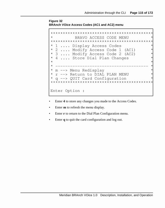
Administration through the CLI Page 115 of 172
• Enter 4 to store any changes you made to the Access Codes.
• Enter m to refresh the menu display.
• Enter r to return to the Dial Plan Configuration menu.
• Enter q to quit the card configuration and log out.
Figure 32BRAnch VOice Access Codes (AC1 and AC2) menu
******************************************* BRAVO ACCESS CODE MENU ******************************************** 1 .... Display Access Codes ** 2 .... Modify Access Code 1 (AC1) ** 3 .... Modify Access Code 2 (AC2) ** 4 .... Store Dial Plan Changes ** ** -------------------------------------- ** m --> Menu Redisplay ** r --> Return to DIAL PLAN MENU ** q --> QUIT Card Configuration *******************************************
Enter Option :
Meridian BRAnch VOice 1.0 Description, Installation, and Operation
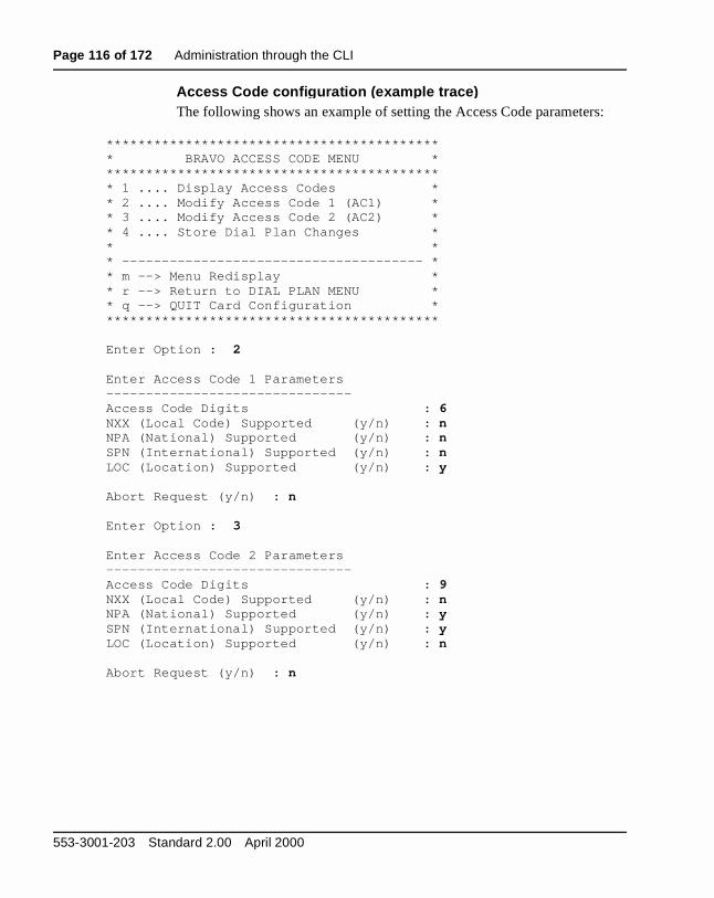
Page 116 of 172 Administration through the CLI
:
Access Code confi guration (example trace )The following shows an example of setting the Access Code parameters****************************************** * BRAVO ACCESS CODE MENU * ****************************************** * 1 .... Display Access Codes * * 2 .... Modify Access Code 1 (AC1) * * 3 .... Modify Access Code 2 (AC2) * * 4 .... Store Dial Plan Changes * * * * -------------------------------------- * * m --> Menu Redisplay * * r --> Return to DIAL PLAN MENU * * q --> QUIT Card Configuration * ******************************************
Enter Option : 2 Enter Access Code 1 Parameters-------------------------------Access Code Digits : 6NXX (Local Code) Supported (y/n) : nNPA (National) Supported (y/n) : nSPN (International) Supported (y/n) : nLOC (Location) Supported (y/n) : y Abort Request (y/n) : n Enter Option : 3 Enter Access Code 2 Parameters-------------------------------Access Code Digits : 9NXX (Local Code) Supported (y/n) : nNPA (National) Supported (y/n) : ySPN (International) Supported (y/n) : yLOC (Location) Supported (y/n) : n Abort Request (y/n) : n
553-3001-203 Standard 2.00 April 2000

Administration through the CLI Page 117 of 172
rs
ed.
des.
Enter Option : 1
*********************************************************** Access Code 1 (AC1) ***********************************************************
Access Code 1 = 6AC1 Dial Plan = LOC
**********************************************************
*********************************************************** Access Code 2 (AC2) ***********************************************************
Access Code 2 = 9AC2 Dial Plan = NPA SPN
**********************************************************
BRAnch VOice Location Code configurationFigure 33 shows the BRAnch VOice Location Code menu, which appeaafter you enter 3 at the Dial Plan configuration menu. By entering 1, 2, 3, or 4 at the “Enter Option:” prompt, the relevant option shown below is invok
At the Location Code menu, you have the following options:
• Enter 1 to display the current Location Codes.
• Enter 2 to add a Location Code.
• Enter 3 to delete a Location Code.
• Enter 4 to store any Dial Plan changes you made to the Location Co
• Enter m to refresh the menu display.
• Enter r to return to the Dial Plan configuration menu.
• Enter q to quit the card configuration and log out.
Meridian BRAnch VOice 1.0 Description, Installation, and Operation

Page 118 of 172 Administration through the CLI
Figure 33BRAnch VOice Location Codes menu
***************************************** ** BRAVO LOCATION CODE MENU ****************************************** ** 1 .... Display Location Codes ** 2 .... Add Location Code ** 3 .... Delete Location Code ** 4 .... Store Dial Plan Changes ** ** -------------------------------------- ** m --> Menu Redisplay ** r --> Return to DIAL PLAN MENU ** q --> QUIT Card Configuration ****************************************** *
Enter Option :
553-3001-203 Standard 2.00 April 2000

Administration through the CLI Page 119 of 172
Location Code confi guration (example trace )The following shows an example of setting Location Codes:
****************************************** * BRAVO DIAL PLAN MENU * ****************************************** * 1 .... Display Dial Plan * * 2 .... Access Codes (AC1 & AC2) (MENU) * * 3 .... Location Codes (MENU) * * 4 .... Distance Steering Codes (MENU) * * 5 .... Trunk Steering Codes (MENU) * * 6 .... Store Dial Plan Changes * * * * -------------------------------------- * * m --> Menu Redisplay * * r --> Return to MAIN MENU * * q --> QUIT Card Configuration * ******************************************
Enter Option : 3 ****************************************** * BRAVO LOCATION CODE MENU * ****************************************** * 1 .... Display Location Codes * * 2 .... Add Location Code * * 3 .... Delete Location Code * * 4 .... Store Dial Plan Changes * * * * -------------------------------------- * * m --> Menu Redisplay * * r --> Return to DIAL PLAN MENU * * q --> QUIT Card Configuration * ******************************************
Enter Option : 1
*********************************************************** Location Codes ***********************************************************
No LOC’s configured ...
**********************************************************
Meridian BRAnch VOice 1.0 Description, Installation, and Operation
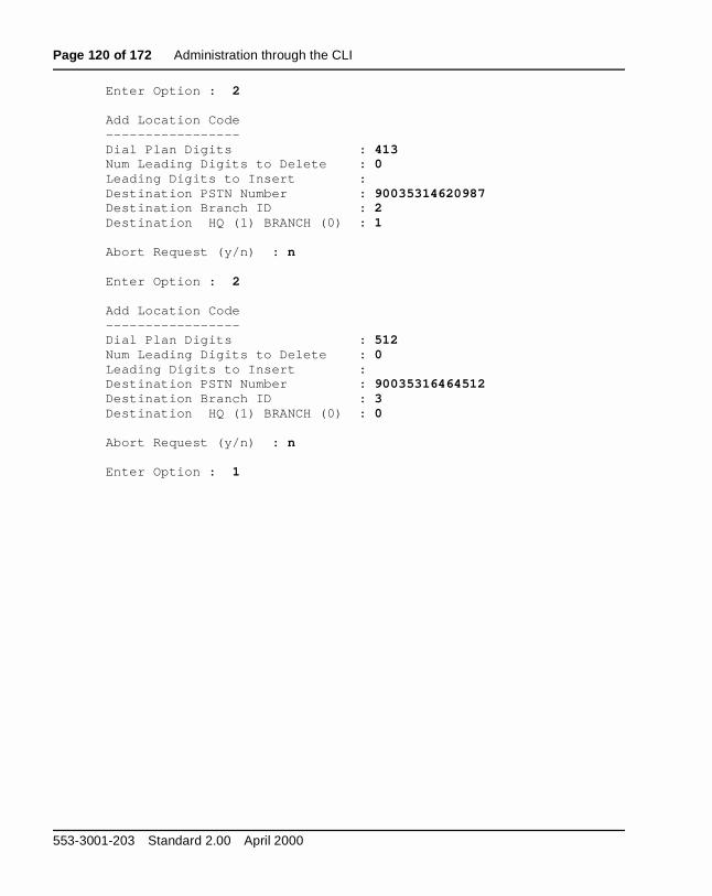
Page 120 of 172 Administration through the CLI
Enter Option : 2 Add Location Code-----------------Dial Plan Digits : 413Num Leading Digits to Delete : 0 Leading Digits to Insert : Destination PSTN Number : 90035314620987Destination Branch ID : 2 Destination HQ (1) BRANCH (0) : 1 Abort Request (y/n) : n Enter Option : 2 Add Location Code-----------------Dial Plan Digits : 512Num Leading Digits to Delete : 0 Leading Digits to Insert : Destination PSTN Number : 90035316464512Destination Branch ID : 3 Destination HQ (1) BRANCH (0) : 0 Abort Request (y/n) : n Enter Option : 1
553-3001-203 Standard 2.00 April 2000

Administration through the CLI Page 121 of 172
*********************************************************** Location Codes ***********************************************************
LOC Entry---------Dial Plan Digits = 413Num Leading Digits to Delete = 0Leading Digits to Insert = Destination PSTN Number = 90035314620987Destination Branch ID = 2Destination Flag (HQ = 1) = 1
LOC Entry---------Dial Plan Digits = 512Num Leading Digits to Delete = 0Leading Digits to Insert = Destination PSTN Number = 90035316464512Destination Branch ID = 3Destination Flag (HQ = 1) = 0
**********************************************************
Enter Option : 3 Delete Location Code--------------------Dial Plan Digits : 413 Abort Request (y/n) : nLOC Entry Deleted ... Enter Option : 1
Meridian BRAnch VOice 1.0 Description, Installation, and Operation

Page 122 of 172 Administration through the CLI
ich
is
*********************************************************** Location Codes ***********************************************************
LOC Entry---------Dial Plan Digits = 512Num Leading Digits to Delete = 0Leading Digits to Insert = Destination PSTN Number = 90035316464512Destination Branch ID = 3Destination Flag (HQ = 1) = 0
**********************************************************
BRAnch VOice Distance Steering Codes configurationFigure 34 shows the BRAnch VOice Distance Steering Codes menu, whappears after you enter 4 at the Dial Plan configuration menu. By entering 1, 2, 3, or 4 at the “Enter Option:” prompt, the relevant option shown below invoked.
Figure 34BRAnch VOice Distance Steering Codes menu
***************************************** ** BRAVO DISTANCE STEERING CODE MENU ****************************************** ** 1 .... Display Distance Steering Codes ** 2 .... Add Distance Steering Code ** 3 .... Delete Distance Steering Code ** 4 .... Store Dial Plan Changes ** ** -------------------------------------- ** m --> Menu Redisplay ** r --> Return to DIAL PLAN MENU ** q --> QUIT Card Configuration ****************************************** *
Enter Option :
553-3001-203 Standard 2.00 April 2000

Administration through the CLI Page 123 of 172
ing
ring
At the Distance Steering Codes configuration menu, you have the followoptions:
• Enter 1 to display the current Distance Steering Codes.
• Enter 2 to add a Distance Steering Code.
• Enter 3 to delete a Distance Steering Code.
• Enter 4 to store any Dial Plan changes you made to the Distance SteeCodes.
• Enter m to refresh the menu display.
• Enter r to return to the Dial Plan Configuration menu.
• Enter q to quit the card configuration and log out.
Distance Steerin g Code confi guration (example trace )The following shows an example of setting Distance Steering Codes:
****************************************** * BRAVO DIAL PLAN MENU * ****************************************** * 1 .... Display Dial Plan * * 2 .... Access Codes (AC1 & AC2) (MENU) * * 3 .... Location Codes (MENU) * * 4 .... Distance Steering Codes (MENU) * * 5 .... Trunk Steering Codes (MENU) * * 6 .... Store Dial Plan Changes * * * * -------------------------------------- * * m --> Menu Redisplay * * r --> Return to MAIN MENU * * q --> QUIT Card Configuration * ******************************************
Meridian BRAnch VOice 1.0 Description, Installation, and Operation

Page 124 of 172 Administration through the CLI
Enter Option : 4 ****************************************** * BRAVO DISTANCE STEERING CODE MENU * ****************************************** * 1 .... Display Distance Steering Codes * * 2 .... Add Distance Steering Code * * 3 .... Delete Distance Steering Code * * 4 .... Store Dial Plan Changes * * * * -------------------------------------- * * m --> Menu Redisplay * * r --> Return to DIAL PLAN MENU * * q --> QUIT Card Configuration * ******************************************
******************************************
Enter Option : 1
*********************************************************** Distance Steering Codes ***********************************************************
Number of DSC Entries = 0
No DSC’s configured ...
**********************************************************
Enter Option : 2 Add Distance Steering Code--------------------------Dial Plan Digits : 713Num Leading Digits to Delete : 1 Leading Digits to Insert : 9Destination PSTN Number : 90035319789781Destination Branch ID : 4 Destination HQ (1) BRANCH (0) : 0 Abort Request (y/n) : n
553-3001-203 Standard 2.00 April 2000
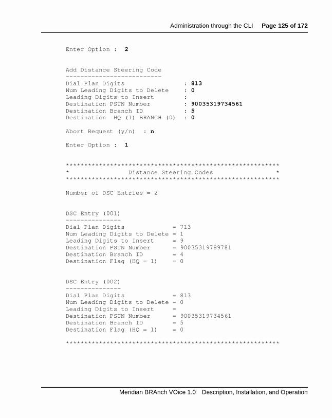
Administration through the CLI Page 125 of 172
Enter Option : 2
Add Distance Steering Code--------------------------Dial Plan Digits : 813Num Leading Digits to Delete : 0 Leading Digits to Insert : Destination PSTN Number : 90035319734561Destination Branch ID : 5 Destination HQ (1) BRANCH (0) : 0 Abort Request (y/n) : n Enter Option : 1
*********************************************************** Distance Steering Codes ***********************************************************
Number of DSC Entries = 2
DSC Entry (001)---------------Dial Plan Digits = 713Num Leading Digits to Delete = 1Leading Digits to Insert = 9Destination PSTN Number = 90035319789781Destination Branch ID = 4Destination Flag (HQ = 1) = 0
DSC Entry (002)---------------Dial Plan Digits = 813Num Leading Digits to Delete = 0Leading Digits to Insert = Destination PSTN Number = 90035319734561Destination Branch ID = 5Destination Flag (HQ = 1) = 0
**********************************************************
Meridian BRAnch VOice 1.0 Description, Installation, and Operation

Page 126 of 172 Administration through the CLI
Enter Option : 3 Delete Distance Steering Code-----------------------------DSC Entry Number : 002 Abort Request (y/n) : nDSC Entry (002) has been deleted
Enter Option : 1
*********************************************************** Distance Steering Codes ***********************************************************
Number of DSC Entries = 2
DSC Entry (001)---------------Dial Plan Digits = 713Num Leading Digits to Delete = 1Leading Digits to Insert = 9Destination PSTN Number = 90035319789781Destination Branch ID = 4Destination Flag (HQ = 1) = 0
DSC Entry (002)---------------This entry has been deleted ....
**********************************************************
BRAnch VOice Trunk Steering Codes configurationFigure 35 shows the BRAnch VOice Trunk Steering Codes configurationmenu, which appears after you enter 5 at the Dial Plan configuration menu. By entering 1, 2, 3, or 4 at the “Enter Option:” prompt, the relevant option shown below is invoked.
At the Trunk Steering Codes menu, you have the following options:
• Enter 1 to display the current Trunk Steering Codes.
• Enter 2 to add a Trunk Steering Code.
• Enter 3 to delete a Trunk Steering Code.
553-3001-203 Standard 2.00 April 2000

Administration through the CLI Page 127 of 172
ng
• Enter 4 to store any Dial Plan changes you made to the Trunk SteeriCodes.• Enter m to refresh the menu display.
• Enter r to return to the Dial Plan configuration menu.
• Enter q to quit the card configuration and log out.
Trunk Steerin g Code confi guration (example trace )The following shows an example of setting Trunk Steering Codes:
****************************************** * BRAVO DIAL PLAN MENU * ****************************************** * 1 .... Display Dial Plan * * 2 .... Access Codes (AC1 & AC2) (MENU) * * 3 .... Location Codes (MENU) * * 4 .... Distance Steering Codes (MENU) * * 5 .... Trunk Steering Codes (MENU) * * 6 .... Store Dial Plan Changes * * * * -------------------------------------- * * m --> Menu Redisplay *
Figure 35BRAnch VOice Trunk Steering Codes menu
****************************************** * BRAVO TRUNK STEERING CODE MENU * ****************************************** * 1 .... Display Trunk Steering Codes * * 2 .... Add Trunk Steering Code * * 3 .... Delete Trunk Steering Code * * 4 .... Store Dial Plan Changes * * * * -------------------------------------- * * m --> Menu Redisplay * * r --> Return to DIAL PLAN MENU * * q --> QUIT Card Configuration * ******************************************
Enter Option :
Meridian BRAnch VOice 1.0 Description, Installation, and Operation

Page 128 of 172 Administration through the CLI
* r --> Return to MAIN MENU * * q --> QUIT Card Configuration * ******************************************
Enter Option : 5 ****************************************** * BRAVO TRUNK STEERING CODE MENU * ****************************************** * 1 .... Display Trunk Steering Codes * * 2 .... Add Trunk Steering Code * * 3 .... Delete Trunk Steering Code * * 4 .... Store Dial Plan Changes * * * * -------------------------------------- * * m --> Menu Redisplay * * r --> Return to DIAL PLAN MENU * * q --> QUIT Card Configuration * ******************************************
553-3001-203 Standard 2.00 April 2000

Administration through the CLI Page 129 of 172
Enter Option : 1
*********************************************************** Trunk Steering Codes ***********************************************************
Number of TSC Entries = 0
No TSC’s configured ...
**********************************************************
Enter Option : 2 Add Trunk Steering Code-----------------------Dial Plan Digits : 213Num Leading Digits to Delete : 0 Leading Digits to Insert : Destination PSTN Number : 90035391234543Destination Branch ID : 7 Destination HQ (1) BRANCH (0) : 0 Abort Request (y/n) : n Enter Option : 2 Add Trunk Steering Code-----------------------Dial Plan Digits : 313Num Leading Digits to Delete : 0 Leading Digits to Insert : Destination PSTN Number : 90035391456123Destination Branch ID : 8 Destination HQ (1) BRANCH (0) : 0 Abort Request (y/n) : n
Meridian BRAnch VOice 1.0 Description, Installation, and Operation

Page 130 of 172 Administration through the CLI
Enter Option : 1
*********************************************************** Trunk Steering Codes ***********************************************************
Number of TSC Entries = 2
TSC Entry (001)---------------Dial Plan Digits = 213Num Leading Digits to Delete = 0Leading Digits to Insert = Destination PSTN Number = 90035391234543Destination Branch ID = 7Destination Flag (HQ = 1) = 0
TSC Entry (002)---------------Dial Plan Digits = 313Num Leading Digits to Delete = 0Leading Digits to Insert = Destination PSTN Number = 90035391456123Destination Branch ID = 8Destination Flag (HQ = 1) = 0
**********************************************************Enter Option : 3 Delete Trunk Steering Code--------------------------TSC Entry Number : 001 Abort Request (y/n) : nTSC Entry (001) has been deleted
553-3001-203 Standard 2.00 April 2000

Administration through the CLI Page 131 of 172
Enter Option : 1
*********************************************************** Trunk Steering Codes ***********************************************************
Number of TSC Entries = 2
TSC Entry (001)---------------This entry has been deleted ....
TSC Entry (002)---------------Dial Plan Digits = 313Num Leading Digits to Delete = 0Leading Digits to Insert = Destination PSTN Number = 90035391456123Destination Branch ID = 8Destination Flag (HQ = 1) = 0
**********************************************************
Enter Option :
Meridian BRAnch VOice 1.0 Description, Installation, and Operation
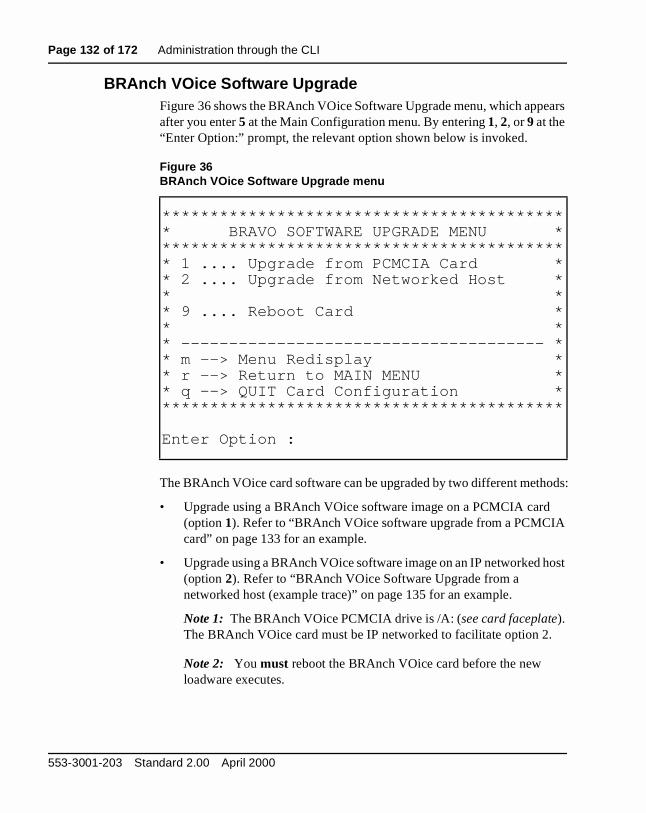
Page 132 of 172 Administration through the CLI
ars
ods:
ost
BRAnch VOice Software UpgradeFigure 36 shows the BRAnch VOice Software Upgrade menu, which appeafter you enter 5 at the Main Configuration menu. By entering 1, 2, or 9 at the “Enter Option:” prompt, the relevant option shown below is invoked.
The BRAnch VOice card software can be upgraded by two different meth
• Upgrade using a BRAnch VOice software image on a PCMCIA card(option 1). Refer to “BRAnch VOice software upgrade from a PCMCIAcard” on page 133 for an example.
• Upgrade using a BRAnch VOice software image on an IP networked h(option 2). Refer to “BRAnch VOice Software Upgrade from a networked host (example trace)” on page 135 for an example.
Note 1: The BRAnch VOice PCMCIA drive is /A: (see card faceplate). The BRAnch VOice card must be IP networked to facilitate option 2.
Note 2: You must reboot the BRAnch VOice card before the new loadware executes.
Figure 36BRAnch VOice Software Upgrade menu
****************************************** * BRAVO SOFTWARE UPGRADE MENU * ****************************************** * 1 .... Upgrade from PCMCIA Card * * 2 .... Upgrade from Networked Host * * * * 9 .... Reboot Card * * * * -------------------------------------- * * m --> Menu Redisplay * * r --> Return to MAIN MENU * * q --> QUIT Card Configuration * ******************************************
Enter Option :
553-3001-203 Standard 2.00 April 2000

Administration through the CLI Page 133 of 172
t be .
• Enter m to refresh the menu display.
• Enter r to return to the Main Configuration menu.
• Enter q to quit the card configuration and log out.
BRAnch VOice software u pgrade from a PCMCIA cardTo upgrade the BRAnch VOice software from a PCMCIA card, there musa card with the appropriate software in the PCMCIA slot on the faceplateYou must know the filename of the upgrade file; it is normally /A:/BRAVO.MMS. The following shows an example of upgrading from aPCMCIA card:
****************************************** * BRAVO CONFIGURATION MENU * ****************************************** * 1 .... General Configuration (MENU) * * 2 .... IP Address Configuration (MENU) * * 3 .... SNMP Trap Configuration (MENU) * * 4 .... Dial Plan Configuration (MENU) * * 5 .... Upgrade Card Software (MENU) * * 6 .... Display System Time * * 7 .... Change System Time * * 8 .... Save Card Configuration * * * * -------------------------------------- * * m --> Menu Redisplay * * q --> QUIT Card Configuration * ******************************************
Enter Option : 5 ****************************************** * BRAVO SOFTWARE UPGRADE MENU * ****************************************** * 1 .... Upgrade from PCMCIA Card * * 2 .... Upgrade from Networked Host * * * * 9 .... Reboot Card * * * * -------------------------------------- * * m --> Menu Redisplay * * r --> Return to MAIN MENU * * q --> QUIT Card Configuration * ******************************************
Meridian BRAnch VOice 1.0 Description, Installation, and Operation

Page 134 of 172 Administration through the CLI
Enter Option : 1 Upgrade BRAVO Software from PCMCIA Card---------------------------------------Use Default file .. /A:/BRAVO.MMS (y/n) : y Abort Request (y/n) : n Upgrading ... Please Wait ...
Opening file /A:/BRAVO.MMSFile /A:/BRAVO.MMS openedFile Length = 0x001749e0Bank Size = 0x00200000Updating sector: 0..1..2..3..4..5..6..7..8..9..10..11..file read complete
Program Address = 0xf9800000Checksum = 0x8c9c4b7flength = 0x1749e0
Upgrade completed OKReboot the pack to run new loadware
Enter Option : 9 Reboot Card Option Chosen !!
Abort Reboot Request (y/n) : nCard is being rebooted ... Resetting card...
553-3001-203 Standard 2.00 April 2000
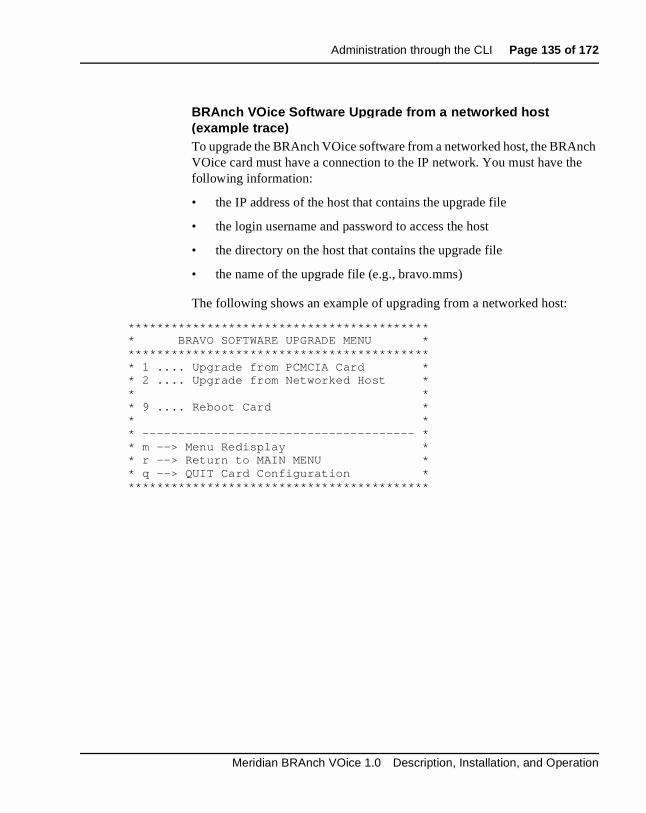
Administration through the CLI Page 135 of 172
ch e
BRAnch VOice Software U pgrade from a networked host (example trace )To upgrade the BRAnch VOice software from a networked host, the BRAnVOice card must have a connection to the IP network. You must have thfollowing information:
• the IP address of the host that contains the upgrade file
• the login username and password to access the host
• the directory on the host that contains the upgrade file
• the name of the upgrade file (e.g., bravo.mms)
The following shows an example of upgrading from a networked host:
****************************************** * BRAVO SOFTWARE UPGRADE MENU * ****************************************** * 1 .... Upgrade from PCMCIA Card * * 2 .... Upgrade from Networked Host * * * * 9 .... Reboot Card * * * * -------------------------------------- * * m --> Menu Redisplay * * r --> Return to MAIN MENU * * q --> QUIT Card Configuration * ******************************************
Meridian BRAnch VOice 1.0 Description, Installation, and Operation

Page 136 of 172 Administration through the CLI
Enter Option : 2 Upgrade BRAVO Software from Networked Host------------------------------------------Enter Host IP Address : 192.31.2.187Enter Username : bravocfg Enter Password : upgrade2 Enter Directory Name : /BRAVO/upgradeEnter Filename : bravo.mms Abort Request (y/n) : n Upgrading ... Please Wait ...
Connecting to 192.31.2.187...connected to 192.31.2.187 OKFile Length = 0x001749e0Bank Size = 0x00200000Updating sector:16..17..18..19..20..21..22..23..24..25..26..27..file read complete
Program Address = 0xf9a00000Checksum = 0x8c9c4b7flength = 0x1749e0
Upgrade completed OKReboot the pack to run new loadware
Enter Option : 9 Reboot Card Option Chosen !!
Abort Reboot Request (y/n) : nCard is being rebooted ... Resetting card...
553-3001-203 Standard 2.00 April 2000

Administration through the CLI Page 137 of 172
ime nd
ime:
Confi gure BRAnch VOice s ystem/card date and timeThere is a real-time clock on the BRAnch VOice card. Enter 6 at the Main Configuration menu to display the current date and time. If the date and tare incorrect, enter 7 at the Main Configuration menu to change the date atime.
Note: After you set the date and time, the date and time updates correctly across card reboots and turning the power off for the card.
System/card date and time confi guration (example trace )The following shows an example of viewing and changing the date and t
****************************************** * BRAVO CONFIGURATION MENU * ****************************************** * 1 .... General Configuration (MENU) * * 2 .... IP Address Configuration (MENU) * * 3 .... SNMP Trap Configuration (MENU) * * 4 .... Dial Plan Configuration (MENU) * * 5 .... Upgrade Card Software (MENU) * * 6 .... Display System Time * * 7 .... Change System Time * * 8 .... Save Card Configuration * * * * -------------------------------------- * * m --> Menu Redisplay * * q --> QUIT Card Configuration * ******************************************
Meridian BRAnch VOice 1.0 Description, Installation, and Operation
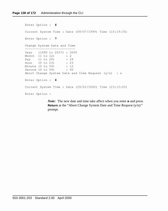
Page 138 of 172 Administration through the CLI
Enter Option : 6 Current System Time : Date (09/07/1999) Time (15:19:35)
Enter Option : 7 Change System Date and Time---------------------------Year (1990 to 2037) : 2000Month (1 to 12) : 2 Day (1 to 29) : 29Hour (0 to 23) : 23Minute (0 to 59) : 12Second (0 to 59) : 00Abort Change System Date and Time Request (y/n) : n Enter Option : 6 Current System Time : Date (29/02/2000) Time (23:12:02)
Enter Option :
Note: The new date and time take affect when you enter n and press Return at the “Abort Change System Date and Time Request (y/n):” prompt.
553-3001-203 Standard 2.00 April 2000
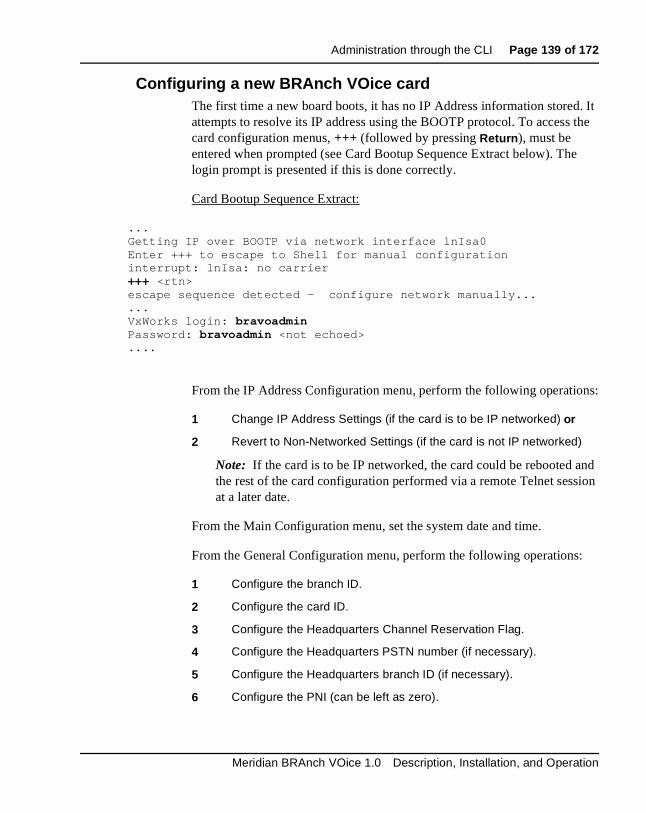
Administration through the CLI Page 139 of 172
. It the
e
ns:
nd sion
:
Configuring a new BRAnch VOice cardThe first time a new board boots, it has no IP Address information storedattempts to resolve its IP address using the BOOTP protocol. To accesscard configuration menus, +++ (followed by pressing Return ), must be entered when prompted (see Card Bootup Sequence Extract below). Thlogin prompt is presented if this is done correctly.
Card Bootup Sequence Extract:
...Getting IP over BOOTP via network interface lnIsa0Enter +++ to escape to Shell for manual configurationinterrupt: lnIsa: no carrier+++ <rtn>escape sequence detected - configure network manually......VxWorks login: bravoadminPassword: bravoadmin <not echoed>....
From the IP Address Configuration menu, perform the following operatio
1 Change IP Address Settings (if the card is to be IP networked) or
2 Revert to Non-Networked Settings (if the card is not IP networked)
Note: If the card is to be IP networked, the card could be rebooted athe rest of the card configuration performed via a remote Telnet sesat a later date.
From the Main Configuration menu, set the system date and time.
From the General Configuration menu, perform the following operations
1 Configure the branch ID.
2 Configure the card ID.
3 Configure the Headquarters Channel Reservation Flag.
4 Configure the Headquarters PSTN number (if necessary).
5 Configure the Headquarters branch ID (if necessary).
6 Configure the PNI (can be left as zero).
Meridian BRAnch VOice 1.0 Description, Installation, and Operation

Page 140 of 172 Administration through the CLI
ct al
7 Configure the End of Call Timeout.
8 Store the Current Card Parameters.
9 Reboot the card.
After the card has rebooted, configure the Dialing Plan and SNMP Trap/Alarm Settings (if required).
Note 1: Changes to the Dialing Plan and Card Parameters take effeimmediately. The changes only survive a card reboot if the "Store DiPlan Changes" and "Store Card Parameters" options are invoked.
Note 2: Changes to the IP Addressing should be followed by an immediate card reboot.
CAUTIONTake extreme care to ensure that no cards in the BRAnch VOice network have the same combination of Branch and card ID. If any twocards in the network have the same combination of Branch and card ID, the conflicting cards do not interwork.
553-3001-203 Standard 2.00 April 2000

Administration through the CLI Page 141 of 172
ing
.
BRAnch VOice shell commandsWhen you exit the menu system, a command line interface, the BRAnch VOice shell, is available. Enter help or ? at the “BRAVO>” shell prompt to list the available shell commands and their descriptions. Enter configureCard or menu at the “BRAVO>” shell prompt to access the MainConfiguration menu of the menu system.
The following shows an example of quitting the card configuration and listthe available shell commands:
shell prompt, the ‘main menu’ of the simple menuing system is displayed
****************************************** * BRAVO CONFIGURATION MENU * ****************************************** * 1 .... General Configuration (MENU) * * 2 .... IP Address Configuration (MENU) * * 3 .... SNMP Trap Configuration (MENU) * * 4 .... Dial Plan Configuration (MENU) * * 5 .... Upgrade Card Software (MENU) * * 6 .... Display System Time * * 7 .... Change System Time * * 8 .... Save Card Configuration * * * * -------------------------------------- * * m --> Menu Redisplay * * q --> QUIT Card Configuration * ******************************************
Meridian BRAnch VOice 1.0 Description, Installation, and Operation

Page 142 of 172 Administration through the CLI
Enter Option : q Do you wish to Save Card Configuration ? (y/n) : ySaving Card Configuration ... ..........Dial Plan File (/C:/TABLE/DPTABLE.1) Saved ... Card Parameters File (/C:/CONFIG/CONFIG1.INI) Saved ... IP Configuration File (/C:/BOOTP/BOOTP.1) Saved ... BRAVO> helpbravoHelp:
bravoHelp Complete Command List. (help or ? are aliases)
configureCard Card Configuration Menus. ( menu is an alias)
swVersionShow Prints out software version.
shellPasswordSet Change the current username and password.
displayDchanStatus Display D-Channel Status and Configuration Info.
upgradeXa 8051XA Firmware Upgrade.
xaSend Send commands to the 8051XA.
loader D-Channel PCMCIA card (/B:) software upgrade.
reformatCdrive Reformat /C: drive (Lose Configuration Files).
archiveConfigToPcmcia Copy configuration files to PCMCIA card (/A:).
copyConfigFromPcmcia Copy configuration files from PCMCIA card (/A:).
archiveOMsToPcmcia Copy OM files to PCMCIA card (/A:)
displayOMFiles Display the contents of the OM files.
copy Copy file command (syntax : copy "src", "dest")
rm Remove file command (syntax : rm "file")
printAlarmInfoOn Turn ON printing of SNMP Alarm Info to the console.
printAlarmInfoOff Turn OFF printing of SNMP Alarm Info to the console.
pingHost Ping a remote host. (syntax : pingHost "ipAddress")
routeAdd Add a route to the network routing table.
routeNetAdd Add destination route network to network routing table.
routeDelete Delete a route from the network routing table.
routeShow Display the current host and network routing tables.
ifShow Display IP parameters.
sysReboot Reboot the card.
i Display the current task status list.
553-3001-203 Standard 2.00 April 2000

Administration through the CLI Page 143 of 172
o
Use the shellPasswordSet command to change the current login ID and password for the BRAnch VOice card. The default is bravoadmin for both. The BRAnch VOice card prompts you for the new login ID and passwordafter you confirm the old login ID and password.
The following commands take parameters:
synopsis: routeAdd "IP address of route destination","IP address of gateway to destination"
synopsis: routeNetAdd "IP address of network destination","IP address of gateway to destination"
synopsis: routeDelete "IP address of route destination","IP address of gateway to destination"
synopsis: pingHost "IP address of remote host"
For example:
BRAVO> routeAdd “47.85.6.83”, “47.85.0.1”
Other commands that take parameters are upgradeXa, xaSend, loader, copy and rm .
The syntax and usage of these commands can be seen in the following sections.
Note: All other commands available from the BRAnch VOice shell dnot take parameters.
D-Channel PCMCIA card u pgradeBefore beginning this process, ensure the BRAnch VOice D-channel is disabled— use DIS DCH X in Overlay 96.
1 Copy the upgrade file to an ATA flash PCMCIA card and insert into slot A of the BRAnch VOice card.
2 Log into the BRAnch Voice card and exit the CLI menu to the BRAnch VOice shell.
3 At the BRAnch VOice shell prompt, type the following:
BRAVO> copy "/A:pcmXX .bin","/C:pcmXX .bin"
Note: XX refers to the version of the file.
4 After the upgrade file is copied, type the following:
Meridian BRAnch VOice 1.0 Description, Installation, and Operation

Page 144 of 172 Administration through the CLI
BRAVO> loader ’1’,"/C:pcmXX.bin"
The card then reports on how the download is proceeding. Onceprogramming is complete, the card automatically reboots.
5 Once reboot completes, the PCMCIA upgrade file can be deleted from drive C:. Enter the shell and type the following:
BRAVO> rm "/C:pcmXX.bin"
8051XA auxiliar y processor u pgrade1 Disable the BRAnch VOice card on the switch.
2 Log into the BRAnch Voice card and exit the CLI menu to the BRAnch Voice shell.
3 At the BRAnch Voice shell, enter the upgradeXa command (syntax below) followed by the sector erase sequence.
BRAVO> upgradeXa "server IP","username","passwd","path","file"
4 Reboot the card. The card will boot using the correct bank of code and FPGAs.
Note: 8051XA upgrade onboard with non-networked settings (i.e. without Ethernet); this upgrade image must be on a PCMCIA card ("/A:").
BRAVO> upgradeXa "10.0.1.2","bravoadmin","bravoadmin","/A:","xaFile.bin"
553-3001-203 Standard 2.00 April 2000
Page 145 of 172
156
his
e. To y. he
tors m
t. It
ice
MaintenanceThis chapter describes Meridian BRAnch VOice 1.0 maintenance tools. Tchapter provides the procedures to:
• identify the BRAnch VOice faults
• locate damaged equipment
• correct problems by repairing or replacing damaged equipment
• check the operation of the BRAnch VOice card after you have madecorrections or replacements
Maintenance overviewIdentify problems step-by-step. A problem can have more than one causidentify the cause, a knowledge of BRAnch VOice operation is necessarWhen you identify the cause, you can correct the problem by replacing tdamaged card or connecting accidentally disconnected cables.
The system and the BRAnch VOice provide integrated diagnostic indicaand software and hardware tools. These diagnostic facilities make systetroubleshooting easier and reduce mean-time-to-repair (MTTR).
This document looks at the maintenance of the BRAnch VOice equipmenrequires that the Meridian 1 system operate correctly before you use a diagnostic test to find the BRAnch VOice card problems.
The system installation and maintenance guide documents: General Maintenance Information (553-3001-500), Fault Clearing (553-3001-510), and Hardware Replacement (553-3001-520) describe how to maintain the complete system. This chapter describes how to maintain the BRAnch VOcard as an integrated part of the system.
Meridian BRAnch VOice 1.0 Description, Installation, and Operation

Page 146 of 172 Maintenance
d y.
the
he l
t s or it to
BRAnch VOice diagnostic toolsUse diagnostic tools to perform troubleshooting on the system including problems with the BRAnch VOice. When you use a diagnostic test to finBRAnch VOice problems, more than one of these tools can be necessar
System diagnostic tools include:
• LED indicators
• display codes
• card self-tests
• sanity monitoring
• overlay commands
LED indicatorsSystem cards are equipped with red LED indicators and module power supplies are equipped with green LED indicators. These indicators showstatus of each card or power supply.
BRAnch VOice maintenance LED indicatorThe BRAnch VOice has a card LED indicator at the top of the faceplate. Tcard LED is a red LED that indicates the status of the card. Under normaconditions, the LED remains off. The LED can be on for the following reasons:
• the card is rebooting
• the card is active, but there are no enabled trunks on the card
• the card is damaged
If the LED is on when the card has enabled trunks and the card does noreboot, the card is damaged. The card is also damaged if the LED flasheis not bright. Replace a faulty card. Package the damaged card and returnthe repair center.
553-3001-203 Standard 2.00 April 2000

Maintenance Page 147 of 172
n
Display codesThe BRAnch VOice has a four-digit alphanumeric maintenance display othe faceplate. The maintenance display indicates the development of theinternal self-test in the form “T:xx”. Table 19 lists the maintenance codeswith their explanations.
Table 19BRAnch VOice alphanumeric display codes (Part 1 of 2)
Self-test code Description
T:00 Initialization
T:01 Testing internal RAM
T:02 Testing ALU
T:03 Testing address modes
T:04 Testing boot ROM
T:05 Testing timers
T:06 Testing watchdog
T:07 Testing external RAM
T:08 Testing host DPRAM
T:09 Testing DS30 DPRAM
T:10 Testing security device
T:11 Testing flash memory
T:12 Programming PCI FPGA
T:13 Programming DS30 FPGA
T:14 Programming CEMUX FPGA
T:15 Programming DSP FPGA
T:16 Testing CE-MUX interface
T:17 Testing EEPROM
Meridian BRAnch VOice 1.0 Description, Installation, and Operation

Page 148 of 172 Maintenance
ou or
ry sum aded and
Self testA self-test is automatically performed by each BRAnch VOice card when yinsert it into an IPE module or Option 11C cabinet, or when you power upreboot the card.
The self-test function performs checks on the hardware, including memotests, bus checks, timer tests, and programmable device checks. Checktests are carried out on application storage space, and the most recently loapplication with a good checksum is selected for execution. The progress
T:18 Booting 486, waiting for response with self-test information
T:19 Waiting for application start-up message from 486
T:20 CardLAN enabled, waiting for Request Configuration Message
T:21 CardLAN in operation, A07 enabled, display now under host control
T:22-99 Reserved for future diagnostic use
EV0x Enabled Voice (Customer-side) BRAnch VOice trunks
FV0x Free Voice trunks
EP0x Enabled PSTN-side BRAnch VOice trunks
FP0x Free PSTN-side trunks
UP00 Upgrade to on-board flash has started (0% complete)
UPnn Upgrade to on-board flash in progress (nn% complete)
UPOK Upgrade to on-board flash correctly completed
UPF Upgrade to on-board flash failed
Table 19BRAnch VOice alphanumeric display codes (Part 2 of 2)
Self-test code Description
553-3001-203 Standard 2.00 April 2000
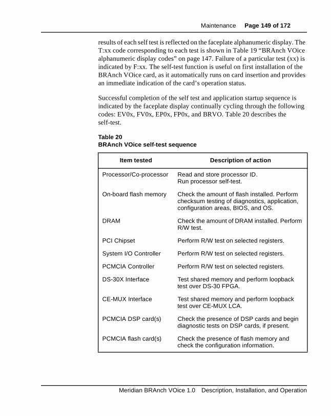
Maintenance Page 149 of 172
. The ice ) is e des
is g
results of each self test is reflected on the faceplate alphanumeric displayT:xx code corresponding to each test is shown in Table 19 “BRAnch VOalphanumeric display codes” on page 147. Failure of a particular test (xxindicated by F:xx. The self-test function is useful on first installation of thBRAnch VOice card, as it automatically runs on card insertion and provian immediate indication of the card’s operation status.
Successful completion of the self test and application startup sequence indicated by the faceplate display continually cycling through the followincodes: EV0x, FV0x, EP0x, FP0x, and BRVO. Table 20 describes the self-test.
Table 20BRAnch VOice self-test sequence
Item tested Description of action
Processor/Co-processor Read and store processor ID. Run processor self-test.
On-board flash memory Check the amount of flash installed. Perform checksum testing of diagnostics, application, configuration areas, BIOS, and OS.
DRAM Check the amount of DRAM installed. Perform R/W test.
PCI Chipset Perform R/W test on selected registers.
System I/O Controller Perform R/W test on selected registers.
PCMCIA Controller Perform R/W test on selected registers.
DS-30X Interface Test shared memory and perform loopback test over DS-30 FPGA.
CE-MUX Interface Test shared memory and perform loopback test over CE-MUX LCA.
PCMCIA DSP card(s) Check the presence of DSP cards and begin diagnostic tests on DSP cards, if present.
PCMCIA flash card(s) Check the presence of flash memory and check the configuration information.
Meridian BRAnch VOice 1.0 Description, Installation, and Operation

Page 150 of 172 Maintenance
tem ce
nes. P
runk ands ble
bled n
.
Sanity monitoringSanity monitoring is a background routine that checks the operation of sysresources, such as memory allocation for CPU activity. This backgroundroutine tries to restore normal system operation if the system performandegrades to a low level. If all else fails, this routine restarts the BRAnch VOice card to try to restore it to normal operation. If the soft reset is not successful, a full board level reset is initiated.
Overlay commandsThe system performs diagnostics for every card as part of the daily routiYou can also perform diagnostics from a maintenance terminal or the SM(when equipped). See Hardware Replacement (553-3001-520)
The BRAnch VOice card appears as an Enhanced Extended Universal Tcard to the system. You can use all important system maintenance commfor an Enhanced Extended Universal Trunk card with BRAnch VOice. Enaand disable the BRAnch VOice units in the Network and Peripheral Equipment Diagnostics program, LD 32. The BRAnch VOice card also terminates a D-channel from the system. This D-channel should be disabefore rebooting or removing the BRAnch VOice card, and enabled wheputting the BRAnch VOice card into service. Table 21 lists some of the commands used to control the BRAnch VOice status and functions. TheBRAnch VOice card executes the commands transparently to the system
Table 21Commands to enable/disable and test BRAnch VOice channels
Overlay Command Operation performed
LD 32 DISC/ENLC Disable/Enable indicated card
LD 32 DISU/ENLU Disable/Enable indicated channel
LD 32 STAT Get status of indicated card/channel
LD 96 DIS DCH x Where x is the number of the D-channel to be enabled or disabled
LD 96 ENL DCH x Where x is the number of the D-channel to be enabled or disabled
553-3001-203 Standard 2.00 April 2000
Maintenance Page 151 of 172
to ure
s with
Fault detection and isolation through alarmsThere are different conditions that can occur that prompt BRAnch VOicesend SNMP Alarms/Traps to assigned SNMP Managers. You can configup to eight SNMP Managers through the BRAnch VOice configuration menus in the Command Line Interface (CLI). You must configure an IP address, gateway, and subnet mask for each SNMP Manager. CustomerMAT 6.5 or greater can use MAT as an SNMP Manager. See “MAT configuration for receiving SNMP Traps/Alarms from BRAnch VOice” onpage 110.
Meridian BRAnch VOice 1.0 Description, Installation, and Operation
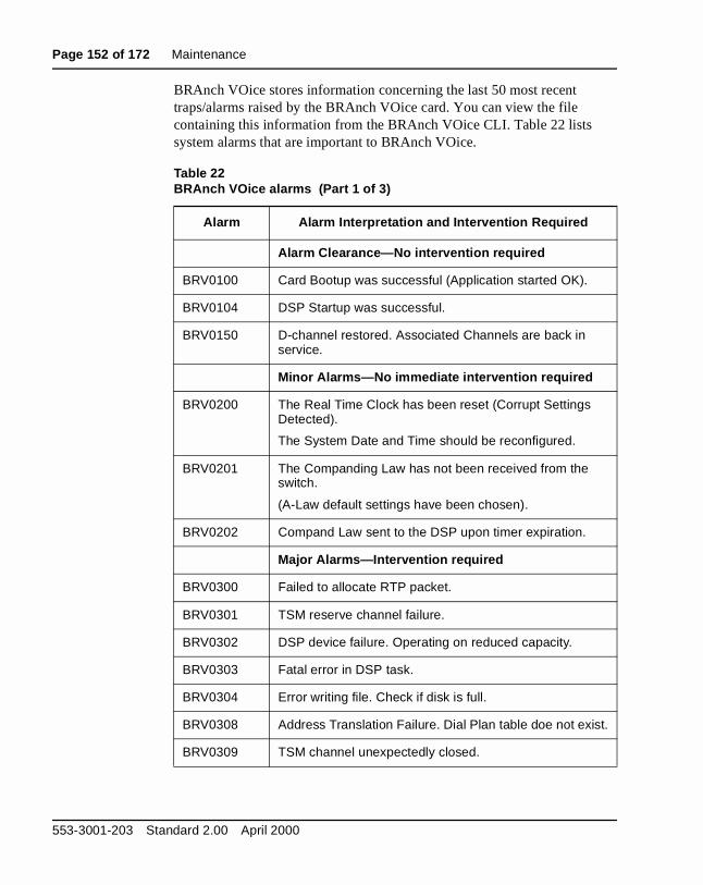
Page 152 of 172 Maintenance
BRAnch VOice stores information concerning the last 50 most recent traps/alarms raised by the BRAnch VOice card. You can view the file containing this information from the BRAnch VOice CLI. Table 22 lists system alarms that are important to BRAnch VOice.
Table 22BRAnch VOice alarms (Part 1 of 3)
Alarm Alarm Interpretation and Intervention Required
Alarm Clearance—No intervention required
BRV0100 Card Bootup was successful (Application started OK).
BRV0104 DSP Startup was successful.
BRV0150 D-channel restored. Associated Channels are back in service.
Minor Alarms—No immediate intervention required
BRV0200 The Real Time Clock has been reset (Corrupt Settings Detected).
The System Date and Time should be reconfigured.
BRV0201 The Companding Law has not been received from the switch.
(A-Law default settings have been chosen).
BRV0202 Compand Law sent to the DSP upon timer expiration.
Major Alarms—Intervention required
BRV0300 Failed to allocate RTP packet.
BRV0301 TSM reserve channel failure.
BRV0302 DSP device failure. Operating on reduced capacity.
BRV0303 Fatal error in DSP task.
BRV0304 Error writing file. Check if disk is full.
BRV0308 Address Translation Failure. Dial Plan table doe not exist.
BRV0309 TSM channel unexpectedly closed.
553-3001-203 Standard 2.00 April 2000

Maintenance Page 153 of 172
Major Alarms—Intervention Required
BRV0404 Unable to read BOOTP File.
BRV0406 Unable to initialize memory pool. Card must be rebooted.
BRV0408 Unable to read Address Translation Table File.
BRV0409 Unable to read Card Parameters File.
BRV0415 Card Bootup was not successful (Task Initialization Failure).
BRV0418 H.323 Stack Initialization Failure.
BRV0450 D-channel loss of signal. Associated channels to be busied out.
BRV0451 D-channel card removed. Associated channels to be busied out.
Table 22BRAnch VOice alarms (Part 2 of 3)
Alarm Alarm Interpretation and Intervention Required
Meridian BRAnch VOice 1.0 Description, Installation, and Operation

Page 154 of 172 Maintenance
elf
Replace a BRAnch VOice cardThe BRAnch VOice card is based on flash EEPROM technology. This technology allows you to remove the BRAnch VOice card from the IPE shwithout losing the configuration data.
Critical/Major Alarms—Intervention Required
BRV0500 Branch and card ID Handshake Failure.
No response from far end Branch.
BRV0501 Branch ID Handshake returned unexpected value.
Far end branch ID is equal to local branch ID.
BRV0502 Branch ID Handshake returned unexpected value.
Does not match value in Address Translation Table for this PSTN DN.
BRV0503 PPP Master-Slave Negotiation Failure.
No response from far end PPP Master Branch.
BRV0504 PPP Master-Slave Negotiation Failure.
No response from far end PPP Slave Branch.
BRV0505 Primary channel in PPP bundle initialization Failure.
Secondary channel timeout waiting for primary to establish.
BRV0506 Point-to-Point Protocol (PPP) Connection Setup Failure.
BRV0507 Unexpected Card Resource Manager State.
BRV0508 Application Message Queue Corrupted.
Table 22BRAnch VOice alarms (Part 3 of 3)
Alarm Alarm Interpretation and Intervention Required
553-3001-203 Standard 2.00 April 2000
Maintenance Page 155 of 172
To replace the BRAnch VOice card:
1 Disable the BRAnch VOice card by loading Overlay 32 and executing the DISC l s c command, where l = loop, s = shelf or module, and c = card in the module. Disable the D-channel by loading Overlay 96 and executing the DIS DCH x command, where x is the D-channel number.
2 Remove the card from its card slot in the IPE module.
3 Remove all PCMCIA cards from the damaged BRAnch VOice card (i. e. the internal PCMCIA card plus associated NTCW84EA pigtail cable and the PCMCIA card installed in the faceplate slot, if any.
4 Transfer all PCMCIA cards to the new BRAnch VOice card.
Note: This procedure moves all software, configuration, and records to the replacement BRAnch VOice card.
5 Install the new BRAnch VOice card into the IPE module card slot.
6 Enable the new card by executing the ENLC l s c command from Overlay 32. Enable the D-channel by executing the ENL DCH x command from Overlay 96.
7 Configure the new installed BRAnch VOice card.
8 Package the damaged BRAnch VOice card and ship it to the repair center.
Meridian BRAnch VOice 1.0 Description, Installation, and Operation

Page 156 of 172 Maintenance
553-3001-203 Standard 2.00 April 2000
Page 157 of 172
142
ds.
ock
Appendix A: Product reliabilit yThis chapter gives information about Meridian BRAnch VOice 1.0 card reliability, environmental specifications, and electrical regulatory standar
Reliabilit yThe Mean Time Between Failure (MTBF) determines the reliability.
Mean time between failure (MTBF)The BRAnch VOice card’s MTBF is 36.95 years.
Environment s pecificationsNortel Networks measured performance in relation to temperature and shunder test conditions. Table 23 describes the results.
Meridian BRAnch VOice 1.0 Description, Installation, and Operation
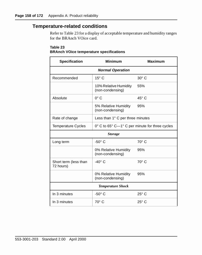
Page 158 of 172 Appendix A: Product reliability
ges
Temperature-related conditionsRefer to Table 23 for a display of acceptable temperature and humidity ranfor the BRAnch VOice card.
Table 23BRAnch VOice temperature specifications
Specification Minimum Maximum
Normal Operation
Recommended 15° C 30° C
10% Relative Humidity (non-condensing)
55%
Absolute 0° C 45° C
5% Relative Humidity (non-condensing)
95%
Rate of change Less than 1° C per three minutes
Temperature Cycles 0° C to 65° C—1° C per minute for three cycles
Storage
Long term -50° C 70° C
0% Relative Humidity (non-condensing)
95%
Short term (less than 72 hours)
-40° C 70° C
0% Relative Humidity (non-condensing)
95%
Temperature Shock
In 3 minutes -50° C 25° C
In 3 minutes 70° C 25° C
553-3001-203 Standard 2.00 April 2000
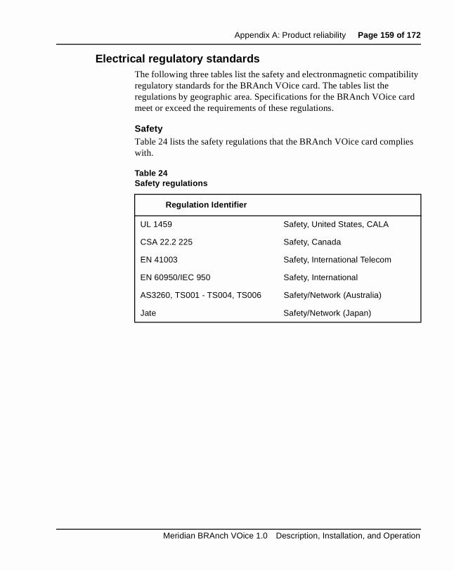
Appendix A: Product reliability Page 159 of 172
lity
rd
es
Electrical regulatory standardsThe following three tables list the safety and electronmagnetic compatibiregulatory standards for the BRAnch VOice card. The tables list the regulations by geographic area. Specifications for the BRAnch VOice cameet or exceed the requirements of these regulations.
SafetyTable 24 lists the safety regulations that the BRAnch VOice card compliwith.
Table 24Safety regulations
Regulation Identifier
UL 1459 Safety, United States, CALA
CSA 22.2 225 Safety, Canada
EN 41003 Safety, International Telecom
EN 60950/IEC 950 Safety, International
AS3260, TS001 - TS004, TS006 Safety/Network (Australia)
Jate Safety/Network (Japan)
Meridian BRAnch VOice 1.0 Description, Installation, and Operation

Page 160 of 172 Appendix A: Product reliability
h
Electroma gnetic com patibilit y (EMC)Table 25 lists the electromagnetic emissions regulations that the BRAncVOice card complies with
Table 26 lists the electromagnetic immunity regulations that the BRAnchVOice card complies with.
Table 25Electromagnetic Emissions
Regulation Identifier
FCC part 15 Class A United States Radiated Emissions
CSA C108.8 Canada Radiated Emissions
EN55022/CISPR 22 CLASS B Radiated Emissions (Basic Standard)
AS/NZS 3548 EMC (Australia/New Zealand)
Table 26Electromagnetic Immunity
Regulation Identifier
CISPR 22 Sec. 20 Class B I/O conducted noise
IEC 801-2 (level 4) ESD (Basic Standard)
IEC 801-3 (level 2) Radiated Immunity (Basic Standard)
IEC 801-4 (level 3) Fast Transient/Burst Immunity (Basic Standard)
IEC 801-5 (level 4, preliminary) Surge Immunity (Basic Standard)
IEC 801-6 (preliminary) Conducted Disturbances (Basic Standard)
AS/NZS 3548 EMC (Australia/New Zealand)
553-3001-203 Standard 2.00 April 2000
Page 161 of 172
142
List of TermsAOC
Advice of Charge.
ATAAnalog Terminal Adapter.
BARSBasic Alternate Route Selection.
BRIBasic Rate Interface.
CALACaribbean and Latin America.
CDBCustomer Data Block.
CDPCoordinated Dialing Plan.
CDRCall Detail Recording.
CE-MUXCommon Emitter/MUltipleXed.
CLICommand Line Interface.
Meridian BRAnch VOice 1.0 Description, Installation, and Operation

Page 162 of 172 List of Terms
Core switchThe Meridian 1 that performs call termination, switching, and routing.
CLSClass of Service.
COCentral Office.
CPDNCalling Party Display Name Display.
CPECustomer Premises Equipment.
CPUCentral Processing Unit.
C7LIUThe VPS card on which the SS7 application exists.
DBBDrop Back Busy.
DCHD-channel.
DIDDirect Inward Dialing.
DNDirectory Number.
DSCDistance Steering Code.
DSPDigital Signal Processor.
553-3001-203 Standard 2.00 April 2000

List of Terms Page 163 of 172
ber
ESNElectronic Switched Network.
EXUTEnhanced Extended Universal Trunk.
flash memor yElectrically erasable non-volatile memory.
FNPFlexible Numbering Plan.
GlareGlare occurs when an incoming and outgoing call contend for the same customer-side trunk. You can reduce glare by using opposite trunk memsearch methods for outgoing and incoming calls.
HQHeadquarters. The main switch in a network, which provides centralizedservices such as NMS and NAS.
IDCIncoming DID Digit Conversion.
IDEIntegrated Drive Electronics.
IGCCISDN Gateway Call Control.
I/OInput/Output.
IPInternet Protocol.
IPEIntelligent Peripheral Equipment.
Meridian BRAnch VOice 1.0 Description, Installation, and Operation

Page 164 of 172 List of Terms
to
ISDNIntegrated Services Digital Network.
ISLISDN Serial Link.
MAT
Meridian Administration Tool. A Nortel Networks proprietary WindowsTM application that you can use to administer the Meridian 1 switch.
MCDNMeridian Customer Defined Network.
MISPMulti-purpose ISDN Signaling Processor.
MMCSMulti-Media Carrier Switch.
MSDLMulti-purpose Serial Data Link.
MTBFMean Time Between Failure.
mana gement LANLAN used for transporting BRAnch VOice configuration, maintenance packets, alarms, and loadware upgrade files.
multi-linkin gWhen the bandwidth of two or more individual data channels is combinedprovide a single, high-bandwidth logical channel by a PPP session.
MWIMessage Waiting Indicator.
NANPNorth America Numbering Plan.
553-3001-203 Standard 2.00 April 2000

List of Terms Page 165 of 172
ities
e
tely.
NARSNetwork Alternate Route Selection.
NASNetwork Attendant Services.
NCA si gnalin gNon-call associated signaling.
NCTNetwork Call Trace.
NFCRNew Flexible Code Restriction.
NMSNetwork Message Services.
Non-call associated si gnalin gNon-call associated signaling is based on the ISDN Transaction CapabilApplication Part (TCAP). Meridian networking makes use of TCAP to activate and report the outcome of supplementary service operations performed without a related call. Because no call exists to provide an application association, TCAP provides a reference. This operation is thtransaction part of TCAP.
NPANumbering Plan Area.
NXXNumbering Plan Exchange.
OA&MOperations, Administration, and Maintenance.
OMOperational Measurement.
PBXPrivate Branch Exchange. A telephony switch the a customer owns priva
Meridian BRAnch VOice 1.0 Description, Installation, and Operation
Page 166 of 172 List of Terms
PCs.
PCMPulse Code Modulation.
PCMCIAPersonal Computer Memory Card International Association. This organization has defined a plug-in disk the size of a credit card for use in
PNIPrivate Network Identifier.
PPPPoint-to-Point Protocol.
PRIPrimary Rate Interface.
PSTNPublic Switched Telephone Network.
RLBRoute List Block.
RLIRoute List Index.
SDISerial Data Interface.
SNMPSimple Network Manager Protocol.
TATTrunk Anti-Tromboning.
TROTrunk Route Optimization.
TSCTrunk Steering Code.
553-3001-203 Standard 2.00 April 2000

List of Terms Page 167 of 172
TSMTelephony Services Manager.
TTYTeletypewriter.
UDPUniform Dialing Plan.
UIPUniversal ISDN Protocol.
UIPCUniversal ISDN Protocol Control.
UIPEUniversal ISDN Protocol Engine.
VPSVoice Processing Server.
WANWide Area Network.
XUTUniversal Trunk Card (Analog Trunk).
Meridian BRAnch VOice 1.0 Description, Installation, and Operation

Page 168 of 172 List of Terms
553-3001-203 Standard 2.00 April 2000

Page 169 of 172
172
Index
AAccess Codes Configuration menu, 114administration, 87Access Codes Configuration menu, 114CLI access, 88Dial Plan Configuration menu, 112Distance Steering Codes Configuration menu,
122General Configuration menu, 90, 91IP Address Configuration menu, 97Location Codes Configuration menu, 117main configuration menu, 88SNMP Traps/Alarms Main menu, 101SNMP Traps/Alarms menu, 105Software Upgrade menu, 132system time and date configuration, 137tasks summary, 87Trunk Steering Codes Configuration menu,
126alarms, 152
Bbranch ID, 23, 47BRAnch VOice alarms, 152BRAnch VOice dialing plan, 17
private network identifier, 17BRAnch VOice hardware requirements, 42
BRAnch VOice networking, 43branch ID and card ID, 47branch/headquarters cluster, 44branch/headquarters node, 43card engineering, 51extension of the MCDN network, 45guidelines, 47IP address reservation, 50number of call hops, 58
branch/headquarters cluster, 44branch/headquarters node, 43
Ccabling, 69
D-channel interface port, 70I/O panel cable, 69management LAN port, 70serial maintenance port, 69
call setup, 29card description, 33
PCMCIA cards, 34supported interfaces, 36
card engineering, 51card ID, 23, 48card installation, 68
available slots, 64card interfaces, 36card replacement, 154
Meridian BRAnch VOice 1.0 Description, Installation, and Operation

Page 170 of 172 Index
CLI, 87Access Codes Configuration menu, 114access to, 88Dial Plan Configuration menu, 112Distance Steering Codes Configuration menu,
122General Configuration menu, 90, 91IP Address Configuration menu, 97Location Codes Configuration menu, 117main configuration menu, 88SNMP Traps/Alarms Main menu, 101SNMP Traps/Alarms menu, 105Software Upgrade menu, 132system time and date configuration, 137tasks summary, 87Trunk Steering Codes Configuration menu,
126Command Line Interface (see CLI), 87configuration, 74
DD-channel interface port, 70diagnostic tools, 146
display codes, 147LED indicators, 146overlay commands, 150sanity monitoring, 150self test, 148
Dial Plan Configuration menu, 112display codes, 147Distance Steering Codes Configuration menu, 122Drop Back Busy, 31
Eelectrical regulatory standards, 159electro-magnetic compatibility, 160engineering
channel reservation, 51HQ/tandem nodes, 56multiple-card branches, 56NCA messaging, 55tandem node cards, 58voice calls, 53
environment specifications, 157electrical regulatory standards, 159electro-magnetic compatibility, 160safety regulations, 159temperature specifications, 158
extension of the MCDN network, 45external equipment requirements, 43
Ffallback, 31fault detection and isolation, 151feature set summary, 27functional description, 24
call setup, 29fallback, 31ISDN signaling link, 28
GGeneral Configuration menu, 90, 91
Hhardware, 39
BRAnch VOice requirements, 42external equipment requirements, 43Meridian 1 requirements, 39
Iinstallation, 61
cabling, 69card installation, 68preparation, 63summary, 62
I/O panel cable, 69IP Address Configuration menu, 97IP address reservation, 50ISDN signaling link, 28
LLED indicators, 146Location Codes Configuration menu, 117
Mmain configuration menu, 88
553-3001-203 Standard 2.00 April 2000

Index Page 171 of 172
maintenance, 145alarms, 152card replacement, 154diagnostic tools, 146fault detection and isolation, 151overview, 145
management LAN port, 70MCDN feature set, 16mean time between failures, 157Meridian 1 hardware requirements, 39multiple-card branches, 23
Nnumber of call hops, 58
Oof X11 system software, 74overlay commands, 150
PPCMCIA cards, 34private network identifier, 17product overview, 15
branch ID and card ID, 23BRAnch VOice dialing plan, 17MCDN feature set, 16multiple-card branches, 23
programming X11 system software, 74
Rrelated NTPs, 10reliability, 157
Ssafety regulations, 159sanity monitoring, 150self test, 148serial maintenance port, 69SNMP Traps/Alarms Main menu, 101SNMP Traps/Alarms menu, 105
software upgradesCLI menu, 132from a networked host, 135from a PCMCIA card, 133
system time and date configuration, 137
Ttemperature specifications, 158Trunk Steering Codes Configuration menu, 126
XX11 system configuration
D-channels, 75dialing plan, 79Incoming Digit Conversion, 84Overlay 15, 74trunk routes, 76trunks, 78
X11 system softwareconfiguration, 74requirements, 37
Meridian BRAnch VOice 1.0 Description, Installation, and Operation

Page 172 of 172 Index
553-3001-203 Standard 2.00 April 2000


Family Product Manual Contacts Copyright FCC notice Trademarks Document number Product release Document release Date Publish
Meridian 1
Meridian BRAnch VOice 1.0Description, Installation, and Operation
Copyright © 1999–2000 Nortel NetworksAll Rights ReservedInformation is subject to change without notice. Nortel Networks reserves the right to make changes in design or components as progress in engineering and manufacturing may warrant. This equipment has been tested and found to comply with the limits for a Class A digital device pursuant to Part 15 of the FCC rules, and the radio interference regulations of Industry Canada. These limits are designed to provide reasonable protection against harmful interference when the equipment is operated in a commercial environment. This equipment generates, uses and can radiate radio frequency energy, and if not installed and used in accordance with the instruction manual, may cause harmful interference to radio communications. Operation of this equipment in a residential area is likely to cause harmful interference in which case the user will be required to correct the interference at their own expense.SL-1 and Meridian 1 are trademarks of Nortel Networks.Publication number: 553-3001-203Document release: Standard 2.00Date: April 2000Printed in Canada


![2017 18 - Intrust Super … · Australia’s hospitality industry union, United Voice [Qld branch], formerly the Liquor, Hospitality and Miscellaneous Union [Qld branch], Fiona Scalon](https://img.dokumen.tips/doc/110x75/60262978e643f75d5a481b2b/2017-18-intrust-super-australiaas-hospitality-industry-union-united-voice.jpg)