Embed Size (px)
Citation preview

Washington University in St. Louis Washington University in St. Louis
Washington University Open Scholarship Washington University Open Scholarship
Mechanical Engineering Design Project Class Mechanical Engineering & Materials Science
Fall 2015
MEMS 411 - Self-Leveling Drone MEMS 411 - Self-Leveling Drone
Sarah Schubert Washington University in St Louis
Anne Shellum Washington University in St Louis
Andreea Stoica Washington University in St Louis
Jillian Rose Washington University in St Louis
Follow this and additional works at: https://openscholarship.wustl.edu/mems411
Part of the Mechanical Engineering Commons
Recommended Citation Recommended Citation Schubert, Sarah; Shellum, Anne; Stoica, Andreea; and Rose, Jillian, "MEMS 411 - Self-Leveling Drone" (2015). Mechanical Engineering Design Project Class. 38. https://openscholarship.wustl.edu/mems411/38
This Final Report is brought to you for free and open access by the Mechanical Engineering & Materials Science at Washington University Open Scholarship. It has been accepted for inclusion in Mechanical Engineering Design Project Class by an authorized administrator of Washington University Open Scholarship. For more information, please contact [email protected].

MEMS Final Report Dec-7 Self-Leveling Drone
Page 1 of 45
The inability to land and take off from uneven terrains is a
major constraint of current helicopters and aerial drones.
The objective of this senior design project was to design
and build an aerial drone with a landing gear system that
would allow leveling and take off from a sloped terrain.
MEMS 411 Final Report
Self-Leveling Drone
Jillian Rose Sarah Schubert Anne Shellum Andreea Stoica
Department of Mechanical Engineering and Materials Science
School of Engineering and Applied Science
Washington University in Saint Louis

MEMS Final Report Dec-7 Self-Leveling Drone
Page 2 of 45
Table of Contents
List of Figures ...................................................................................................................................... 5
List of Tables ....................................................................................................................................... 6
1 Introduction .................................................................................................................................... 7
1.1 Project problem statement ..................................................................................................... 7
1.2 List of team members ............................................................................................................. 7
2 Background Information Study ....................................................................................................... 7
2.1 A short design brief description that defines and describes the design problem .................. 7
2.2 Summary of relevant background information ...................................................................... 7
2.2.1 Patents: ........................................................................................................................... 7
2.2.2 Articles and URLs:............................................................................................................ 7
3 Concept Design and Specification ................................................................................................... 8
3.1 Performance Metrics and Measures....................................................................................... 8
3.2 Concept drawing ..................................................................................................................... 8
3.3 Concept Selection and Feasibility ........................................................................................... 9
3.4 Design Constraints .................................................................................................................. 9
3.4.1 Functional ........................................................................................................................ 9
3.4.2 Safety .............................................................................................................................. 9
3.4.3 Quality ............................................................................................................................. 9
3.4.4 Manufacturing................................................................................................................. 9
3.4.5 Timing ............................................................................................................................ 10
3.4.6 Economic ....................................................................................................................... 10
3.4.7 Ergonomic ..................................................................................................................... 10
3.4.8 Ecological ...................................................................................................................... 10
3.4.9 Aesthetic ....................................................................................................................... 10
3.4.10 Life cycle ........................................................................................................................ 10
3.4.11 Legal .............................................................................................................................. 10
4 Embodiment and fabrication plan ................................................................................................ 11
4.1 Embodiment drawing............................................................................................................ 11
4.2 Parts List ................................................................................................................................ 11
4.3 Draft detail drawings for each manufactured part ............................................................... 12
4.4 Description of the design rationale for the choice/size/shape of each part ........................ 15
4.4.1 Frame Configuration ..................................................................................................... 15

MEMS Final Report Dec-7 Self-Leveling Drone
Page 3 of 45
4.4.2 Electronic Components ................................................................................................. 17
4.5 Gantt chart ............................................................................................................................ 19
5 Engineering analysis ...................................................................................................................... 20
5.1 Engineering analysis proposal ............................................................................................... 20
5.1.1 A form, signed by your section instructor..................................................................... 20
5.2 Engineering analysis results .................................................................................................. 20
5.2.1 Motivation. Describe why/how the before analysis is the most important thing to
study at this time. How does it facilitate carrying the project forward? ..................................... 20
5.2.2 Summary statement of analysis done. Summarize, with some type of readable
graphic, the engineering analysis done and the relevant engineering equations ........................ 21
5.2.3 Methodology. How, exactly, did you get the analysis done? Was any
experimentation required? Did you have to build any type of test rig? Was computation used?
21
5.2.4 Results. What are the results of your analysis study? Do the results make sense? ... 22
5.2.5 Significance. How will the results influence the final prototype? What dimensions
and material choices will be affected? ......................................................................................... 25
5.2.6 Summary of code and standards and their influence. Similarly, summarize the
relevant codes and standards identified and how they influence revision of the design. ........... 25
5.3 Risk Assessment .................................................................................................................... 27
5.3.1 Risk Identification .......................................................................................................... 27
5.3.2 Risk Analysis .................................................................................................................. 27
5.3.3 Risk Prioritization .......................................................................................................... 28
6 Working prototype ........................................................................................................................ 30
6.1 A preliminary demonstration of the working prototype (this section may be left blank). .. 30
6.2 A final demonstration of the working prototype (this section may be left blank). .............. 30
6.3 At least two digital photographs showing the prototype ..................................................... 30
6.4 A short videoclip that shows the final prototype performing .............................................. 31
6.5 At least four (4) additional digital photographs and their explanations .............................. 31
7 Design documentation .................................................................................................................. 35
7.1 Final Drawings and Documentation ...................................................................................... 35
7.1.1 A set of engineering drawings that includes all CAD model files and all drawings
derived from CAD models. ............................................................................................................ 35
7.1.2 Sourcing instructions ..................................................................................................... 35
7.2 Final Presentation ................................................................................................................. 35
7.2.1 A live presentation in front of the entire class and the instructors .............................. 35
7.2.2 A link to a video clip version of 1 .................................................................................. 35

MEMS Final Report Dec-7 Self-Leveling Drone
Page 4 of 45
7.3 Teardown .............................................................................................................................. 35
8 Discussion ...................................................................................................................................... 36
8.1 Using the final prototype produced to obtain values for metrics, evaluate the quantified
needs equations for the design. How well were the needs met? ................................................... 36
8.2 Discuss any significant parts sourcing issues? ...................................................................... 36
8.3 Discuss the overall experience: ............................................................................................. 36
8.3.1 Was the project more of less difficult than you had expected? ................................... 36
8.3.2 Does your final project result align with the project description? ............................... 36
8.3.3 Did your team function well as a group? ...................................................................... 36
8.3.4 Were your team member’s skills complementary? ...................................................... 37
8.3.5 Did your team share the workload equally? ................................................................. 37
8.3.6 Was any needed skill missing from the group? ............................................................ 37
8.3.7 Did you have to consult with your customer during the process, or did you work to the
original design brief? ..................................................................................................................... 37
8.3.8 Did the design brief (as provided by the customer) seem to change during the
process? 37
8.3.9 Has the project enhanced your design skills? ............................................................... 37
8.3.10 Would you now feel more comfortable accepting a design project assignment at a
job? 37
8.3.11 Are there projects that you would attempt now that you would not attempt before?
38
9 Appendix A - Parts List .................................................................................................................. 39
10 Appendix B - Bill of Materials .................................................................................................... 39
11 Appendix C - CAD Models ......................................................................................................... 40
12 Annotated Bibliography ............................................................................................................ 44

MEMS Final Report Dec-7 Self-Leveling Drone
Page 5 of 45
List of Figures Figure 1: Concept Drawing: Linked Bar Leveling System. ....................................................................... 8
Figure 2: Embodiment Drawing ………………………………………………………………………………………………………11
Figure 3: Base Plate ……………………………………………………………………………………….………………………………..12
Figure 4: Controller Connector………………………………………………………………………………………….……………..13
Figure 6: T-Arm ………………………………..……………………………………………………………………………………………..14
Figure 7: Landing Gear……………………………………………………………………………………………………………………..14
Figure 8: Lower Leg…………………………………………………………………..……………………………………………………..15
Figure 9: Summary of engineering analysis done before building the prototype……………………………..21
Figure 10: Large and Small Servos …………………………………………………………………………………………………..22
Figure 11: 2000 kV Brushless Motor and 7x4E Propeller……………………………………………………..…………..23
Figure 12: Final Circuit Schematic ……………………………………………………………………………………..…………..23
Figure 13: Initial Prototype and Final Prototype…………………….………………………………………………………..25
Figure 14: Initial Working Prototype………………………………………………………………………………………………..30
Figure 15: Final Working Prototype……………………………………………………..…………………………………………..31
Figure 16: Close up of the hinged landing gear joints..………………………………………………..…………………..32
Figure 17: Accelerometer and Flight Controller..…………………………………………………………..…………………33
Figure 18: Quad-copter at an approximately 15 degree angle during testing…………………………………..33
Figure 19: Close up of the full circuit.…………………………………………………………………………….………………..34
Figure 20: Teardown agreement……………………………………………………………………………………………………..35

MEMS Final Report Dec-7 Self-Leveling Drone
Page 6 of 45
List of Tables Table 1: Initial Parts List ........................................................................................................................ 11
Table 2: Gantt Chart .............................................................................................................................. 19
Table 3: Risk identification, corresponding events, and effects on project.......................................... 26
Table 4: Potential effects specification for Table 3 ............................................................................... 27

MEMS Final Report Dec-7 Self-Leveling Drone
Page 7 of 45
1 Introduction
1.1 Project problem statement
1.2 The objective of this senior design project was to design and build an aerial drone with a
landing gear system that would allow leveling and take off from a sloped terrain. The drone
should be able to level on a slope with a maximum incline of 20 degrees and the leveling
process should not exceed 30 seconds. In addition, the leveling system must be automatic and
deployed using the flight controller.
1.3 List of team members
Jillian Rose
Sarah Schubert
Anne Shellum Andreea Stoica
2 Background Information Study
2.1 A short design brief description that defines and describes the design
problem
The goal of this project was driven by a major constraint on current helicopters and aerial drones -
inability to land and take off from uneven terrains. Thus the team was tasked with designing and
building an aerial drone with a landing gear system that would allow it to level and take off from a
sloped surface.
2.2 Summary of relevant background information
2.2.1 Patents:
US 3857533 A - Helicopter self-leveling landing gear
US 9033276 B1 - Telescoping landing leg system
US 20100012776 A1 - Method for Vertical Takeoff from and Landing on
Inclined Surfaces
S 9145207 B2 - Remotely controlled micro/nanoscale aerial vehicle comprising
a system for traveling on the ground, vertical takeoff, and landing
2.2.2 Articles and URLs:
DARPA Leveling Landing Gear
NASA Passive Self-Leveling Landing Gear

MEMS Final Report Dec-7 Self-Leveling Drone
Page 8 of 45
3 Concept Design and Specification
3.1 Performance Metrics and Measures
The drone must be able to fly in order to demonstrate leveling gear. Desired flight time is five
minutes.
The drone weight should not exceed 5 lbs.
The drone must be able to level from a maximum incline of 20 degrees.
The leveling gear must function repeatedly. Desired lifetime is 100 take-offs.
The user must be able to deploy landing gear using the flight controller.
The leveling process should not exceed 30 seconds.
The drone should be able to level from any orientation.
The leveling landing gear should stay folded during flight and refold upon takeoff.
3.2 Concept drawing
Figure 1: Concept Drawing – Linked Bar Leveling System

MEMS Final Report Dec-7 Self-Leveling Drone
Page 9 of 45
3.3 Concept Selection and Feasibility The concept selections were broken down into two separate design components: flight system and
leveling system. For the flight system both single-rotor configuration and quadcopter configurations
were considered. The quadcopter configuration was selected as it allows for thrust distribution among
the four motors, it provides better balancing capabilities in flight and it offers more freedom in placing
the leveling system. In selecting a leveling system configuration multiple concepts were considered
including telescoping legs, single bar actuated landing gear and the double linked bar leveling system.
The double linked bar leveling system was selected due to the reduced load on each of the leveling
system segments, the simplicity of the design and leveling algorithm, and the relatively lower weight
and energy consumption of the actuators.
3.4 Design Constraints
3.4.1 Functional
The most challenging functional constraint in our design was energy. Batteries are by far the heaviest
component on a quadcopter and we were therefore limited to at most two 3000 mAh lithium-ion
polymer batteries (for a total of 6 Amp-hours of charge). Each of the four motors used for flight
consume significant amounts of power (360 watts at their maximum), as did the eight servo motors
controlling the self-leveling landing gear.
3.4.2 Safety
As with any engineering project, there were many safety constraints to consider. One of the biggest
safety concerns in quad-copter design is the damage that can be done by the propellers when
powering on the quad-copter. To protect against unwanted propeller damage a failsafe was added to
the flight control configuration such that the propellers must be manually armed before they will spin
each time the quadcopter is connected to power.
3.4.3 Quality
The quality of the electronic components, in particular the servos was a constant challenge in this
project. Four of the eight servos needed to be replaced because their plastic internal gears could not
consistently handle the torque needed to lift the quad-copter. The remaining four servos did not have
the accuracy needed to achieve perfect leveling.
3.4.4 Manufacturing
The speed of manufacture of this design could be greatly improved by either injection molding most
of the body components or by using laser cutting for the metal components. As it stands this design
was made entirely with manual and CNC milling, which are time and labor intensive.

MEMS Final Report Dec-7 Self-Leveling Drone
Page 10 of 45
3.4.5 Timing
The largest timing constraint on this project was the roughly two month maximum time frame in which
it needed to be completed. This very short time frame was made more challenging by the need to
order most necessary components online. The combination of these two timing constraints led to
many less than optimal materials and electrical components being used.
3.4.6 Economic
The overall budget for this project was $400. While the initial design was able to fit within this budget,
broken and malfunctioning equipment forced the project to go over.
3.4.7 Ergonomic
One of the most critical user needs constraints for any RC design is compatibility with standard RC
controllers. In order to make our design compatible with most RC controllers as well as capable of
controlling both the flight and leveling circuits on the quad-copter a standard Spektrum AR6210 6-
channel DSMX Receiver was used.
3.4.8 Ecological
The most pressing ecological consideration of our project is the potential damage that the lithium-ion
polymer batteries could have on the environment. Of particular concern is the possibility that, if
damaged during flight or because of a crash landing, the batteries pose a potential fire hazard. The
best method of preventing a fire caused by crash landing is housing the batteries such that they are
protected from shock and all sharp objects.
3.4.9 Aesthetic
Of greatest aesthetic concern in our design is the exposed circuitry. While exposed wiring is ideal for
prototyping because it allows for easy modification, for a final commercial design all circuitry
components should be housed such that they are not visible.
3.4.10 Life cycle
As for most quadcopter designs, this product would require some maintenance throughout its
functional life. In addition to consistently charging and replacing batteries when needed, it is very
common to need to replace broken propellers. All other components would be difficult to repair or
replace
3.4.11 Legal
The legal implications of flying drones as a hobbyist continue to evolve and grow more rigorous. The
Federal Aviation Administration is responsible for ensuring safe and responsible use of all unmanned
aircraft, including quad-copters. The FAA regulations for hobby and recreational use of model
aircraft are given in section 5.2.6.

MEMS Final Report Dec-7 Self-Leveling Drone
Page 11 of 45
4 Embodiment and fabrication plan
4.1 Embodiment drawing
Figure 2: Embodiment Drawing
4.2 Parts List Table 1: Initial Parts List
ITEM NO. PART DESCRIPTION QTY.
1 QuadSkeleton 2
2 Base Plate 1
3 Controller connectors 1
4 T-Arm1 1
5 T-Arm2 1
6 T-Arm3 1
7 Controller board 1
8 3000mAh Batteries 1
9 Props 1

MEMS Final Report Dec-7 Self-Leveling Drone
Page 12 of 45
10 SubBase Plate 1
11 Landing Gear 1
12 Folding leg 1 1
13 Upper leg 3 1
14 Upper leg2 1
15 Upper leg3 1
16 Lower Leg 4
17 Upper Servos 1
18 Single Servo 4
19 Motors 1
20 DSMX Receiver 1
21 Electronic Speed Controllers 1
22 Flight Controller 1
23 Servo Controller 1
4.3 Draft detail drawings for each manufactured part
Figure 3: Base Plate

MEMS Final Report Dec-7 Self-Leveling Drone
Page 13 of 45
Figure 4: Controller Connector
Figure 5: Sub-Base Plate

MEMS Final Report Dec-7 Self-Leveling Drone
Page 14 of 45
Figure 6: T-Arm
Figure 7: Landing gear

MEMS Final Report Dec-7 Self-Leveling Drone
Page 15 of 45
Figure 8: Lower Leg
4.4 Description of the design rationale for the choice/size/shape of each
part
4.4.1 Frame Configuration
4.4.1.1 Overall Considerations
A quadcopter configuration was chosen for the frame design due to its symmetrical configuration
and ease of control, as movement in any direction can be achieved by controlling the trust of each
motor. In order to incorporate the stabilizing landing gear, spacing between the quadcopter arms
was maximized by choosing a plus type configuration (arms perpendicular to each other). As the
frame represents the structural element of the quadcopter, it needs to be able to support the weight
of the electronic components and withstand the bending moments caused by the rotating
propellers, while being as lightweight as possible. Thus the shape and material of each frame
element were chosen with the goal of obtaining the best compromise between weight and strength,
while also taking machinability and price into consideration.
4.4.1.2 Arms
The main failure mechanism of the quadcopter arms is bending failure due to the bending moments
created by the propellers thrust. Aluminum, fiber reinforced plastics (both carbon and glass fiber),
acrylic, PVC, and ABS were considered as candidate materials. Although arms made from fiber

MEMS Final Report Dec-7 Self-Leveling Drone
Page 16 of 45
reinforced plastics would represent the best option from a weight-strength perspective, their
significantly higher cost and difficulty in machining eliminated them as an option. Acrylic, PVC, and
ABS tubes are comparable in price to aluminum, however their larger flexibility (lower Young’s
modulus) would result in higher beam deflections while the propellers are running. In addition, the
shape and size of acrylic, PVC, and ABS tubes/beams is limited by what can be found on the market.
Thus the selected material for the quadcopter arms was 0.08” thick aluminum 5052-H32 sheet due to
its increased strength and ease of machinability. A T-beam design was chosen as it provides an
increase in material strength and a decrease in weight in comparison to other geometries such as solid
rectangular rods or hollow rectangular beams. The T-beam geometry will be constructed by
connecting two 0.08 in thick and 0.5 in wide aluminum sheets. The two arms will be connected under
the base plate. In order to prevent the arms from crossing each other under the base plate, one arm
will be cut into two shorter pieces.
4.4.1.3 Center Plates
The center plates act as the connection point for the quadcopter arms and provide support for all the
electronic components. Both acrylic and aluminum sheets were considered as material candidates. In
order to reduce the weight of the frame, a 0.08 in thick acrylic sheet was chosen as the material.
4.4.1.4 Landing Gear
The landing legs will have the role of providing the initial landing support for the quadcopter. Thus
they will have to be able to support the quadcopter weight, as well as be able to withstand any bending
moments created as the quadcopter will stabilize itself before taking off. The maximum bending
moments on the landing legs will be dependent on the load distribution over the four landing legs and
four stabilizing legs. Given the strength of aluminum and the fact that aluminum sheets are used for
hexapod legs, 0.08” in thick 5052-H32 aluminum sheets were chosen as the leg material. However,
further analysis of the maximum bending moments on the landing legs is required in order to
determine the appropriate leg material and thickness and given the complexity of the problem,
consultation with a MEMS faculty member is required.
4.4.1.5 Stabilizing Legs
The stabilizing leg design was broken down by length, form, and material with the goal of being
capable of supporting the weight of the quadcopter and taking the quadcopter from a 20 degree
maximum tilt to perpendicular to the gravitational pull. The necessary length for achieving this
maximum leveling angle was calculated to be 4 ⅓ inches. As the first failure point of the stabilizing legs
would be caused by bending, an accurate estimate of the bending moments acting on each stabilizing
leg is needed. We have completed preliminary computations, however as this represents a complex
problem we plan to contact a MEMS faculty member to review our computations. Our original leg

MEMS Final Report Dec-7 Self-Leveling Drone
Page 17 of 45
design required two leg segments, each comprised of two parallel bars joined by a servo motor (four
total pieces). It was later decided that the added weight of putting two bars in parallel for each leg
segment was not justified given the strength of aluminum. Our calculations for torque and lift
requirements were based on a no slip condition at the point where the leg contacts the ground. A
rubber treaded foot was designed to meet this requirement.
4.4.2 Electronic Components
4.4.2.1 Overall Considerations
There are multiple ways to execute almost any circuit, so the focus throughout the circuit design was
simplification. The easiest way to accomplish this goal was to use one power source for the drone
flight control, sensors, Arduino, and servo motors. Although this resulted in the need for a Battery
Eliminator Circuit (BEC), the condensed geometry of a single battery pack allowed for significant design
improvements to the structure.
4.4.2.2 Accelerometer
To determine the angle required to stabilize the drone, both a gyroscope and an accelerometer were
considered. An accelerometer was chosen because it calculates required stabilization angle on a fixed
reference point, whereas gyroscopes only measure angular changes. Accelerometers options ranged
from fine-grained measurement of +/- 2g (accuracy of 2 / 1024 = 0.002g), to +/-16g (accuracy of 16 /
1024 = 0.0156.) The selected mode has a digitally outputs the x, y, and z position, compatible with our
selected microprocessor.
4.4.2.3 Microcontroller
Servo motors are controlled by Pulse Width Modulation (PWM). As such, our microcontroller should
contain at least 8 PWM pins. Models that include the number of required pins were found to be overly
complex and heavy for our design requirements. Instead, a PWM shield was selected to supplement
the standard Arduino Uno processor.
4.4.2.4 Servos
The maximum torque on the servo motors must be calculated before making a selection. In order to
simplify initial calculations, the following assumptions were made:
At most, the entire weight of the drone could be placed on one lifting leg (this is very
conservative, and will prevent overloading of the servo).
The maximum torque occurs in the leg elbow at the moment when the leg touches the ground,
when the moment arm will be the longest.
The total force was modeled by a point force acting at the point of the top pin.

MEMS Final Report Dec-7 Self-Leveling Drone
Page 18 of 45
These broad simplifications do not provide a sufficiently accurate torque for final design. The
complexity of the torque force is such that expert consultation will be sought. Given the essential
function of the motors, it is important that this calculation be done correctly before sourcing specific
motors.
The angle turned by each positive pulse to the servo and the speed at which the pulses would be
emitted will also be into account to ensure that quick rotation will not throw the drone off-balance.
A model will that is capable of communicating with our chosen microcontroller will be selected.
A typical small-sized servo draws about 150 mAmp running with no load. This draw increases with
torque on the motor. Online literature suggests that the maximum draw for a servo motor of this size
is 1.5 amps, a relatively low load on the battery compared to the propeller motors.
4.4.2.5 BEC
The battery eliminating circuit was selected based on its ability to handle up to 8 servos at 5-V. It is
recommended for high torque applications and will not create radio interference if located more than
2” inches from the receiver. This configuration is possible given current geometry restrictions.
4.4.2.6 Propellers and Motors
The propellers and motor were selected based on the static thrust requirements. The static thrust that
the quad-copter can produce is a function of the Kv rating of the motors, the type, diameter and pitch
of the propellers, the voltage drop over the motors, and a number of other variables. Using the
equations below the static thrust for several combinations of propellers and motors was calculated.
In order to balance the thrust with the size and weight of the quad-copter, 7x4E APC propellers (Thin-
electric propellers with a 7 inches diameter and 4 inch pitch) were paired with 2000 Kv motors.
Assuming an applied voltage of 11V, the calculated thrust is approximately 3.35 lbs/motor (or 1.51
Kg/motor).
Thrust equations used [1]:
Thrust created by one propeller:
𝑇 = 𝜋
4𝐷2𝜌ν∆ν =
𝜋
8𝐷2𝜌(∆ν)2
T = thrust [N]
D = propeller diameter [m]
ν = velocity of air at the propeller [m/s]
Δν = velocity of air accelerated by propeller [m/s]
ρ = density of air [1.225 kg/m3]

MEMS Final Report Dec-7 Self-Leveling Drone
Page 19 of 45
The velocity of air accelerated by the motor can be found using the power that is absorbed by the
propeller from the motor:
𝑃 = 𝑇∆𝜈
2→ ∆ν =
2𝑃
𝑇
Substituting for ∆ν, one can calculate the thrust by using the following equation:
𝑇 = [𝜋
2𝐷2𝜌𝑃2]
1/3
This can be expressed in terms of mass using the following equation:
𝑚 = [𝜋2
𝐷2𝜌𝑃2]1/3
𝑔
Where g = 9.81 m/s2.
We confirmed our calculations using online thrust calculators as well. [2, 3]
4.4.2.7 Transmitter
The controller we will be using to fly the drone is a Spektrum DX5E borrowed from ASME. The only
requirement for a transmitter was that it be compatible with this controller and have at least 5
channels.
4.5 Gantt chart Table 2: Gantt Chart
Period Highlight: 30 Plan Actual % Complete Actual (beyond plan) % Complete (beyond plan)
08
/24
/15
08
/26
/15
08
/28
/15
08
/30
/15
09
/01
/15
09
/03
/15
09
/05
/15
09
/07
/15
09
/09
/15
09
/11
/15
09
/13
/15
09
/15
/15
09
/17
/15
09
/19
/15
09
/21
/15
09
/23
/15
09
/25
/15
09
/27
/15
09
/29
/15
10
/01
/15
10
/03
/15
10
/05
/15
10
/07
/15
10
/09
/15
10
/11
/15
10
/13
/15
10
/15
/15
10
/17
/15
10
/19
/15
10
/21
/15
10
/23
/15
10
/25
/15
10
/27
/15
10
/29
/15
10
/31
/15
11
/02
/15
11
/04
/15
11
/06
/15
11
/08
/15
11
/10
/15
11
/12
/15
11
/14
/15
11
/16
/15
11
/18
/15
11
/20
/15
11
/22
/15
11
/24
/15
11
/26
/15
11
/28
/15
11
/30
/15
12
/02
/15
12
/04
/15
12
/06
/15
12
/08
/15
12
/10
/15
12
/12
/15
1 2 3 4 5 6 7 8 9 10 11 12 13 14 15 16 17 18 19 20 21 22 23 24 25 26 27 28 29 30 31 32 33 34 35 36 37 38 39 40 41 42 43 44 45 46 47 48 49 50 51 52 53 54 55 56
1 Elevator Pitch 1 4 2 2 100%
2 Project Selection 1 6 4 2 100%
3Background
Information Study1 4 2 3 100%
4Concept Design and
Specification 9 4 9 4 100%
5Project Re-evaluation
& New Concept0 0 15 3 100%
6Embodiment and
Fabrication Plan12 8 15 5 100%
7Engineering Analysis
Proposal 15 4 15 4 100%
8 Part Ordering 22 3 23 4 100%
9Engineering Analysis
Analysis 24 20 25 17 100%
10 Working Prototype 20 18 30 8 100%
11 Second Part Ordering 36 4 36 4 90%
12 Final Prototype 38 6 40 6 75%
13 Final Drawings 44 6 44 6 100%
14 Final Presentation 47 4 48 2 100%
15 Final Report 30 24 42 12 100%
16 Final Teardown 51 2 52 1 100%
PERIODS
MEMS 411 Senior Project
PLAN
START
PLAN
DURATION
ACTUAL
START
ACTUAL
DURATION
PERCENT
COMPLET
EACTIVITY

MEMS Final Report Dec-7 Self-Leveling Drone
Page 20 of 45
5 Engineering analysis
5.1 Engineering analysis proposal
5.1.1 A form, signed by your section instructor
5.2 Engineering analysis results
5.2.1 Motivation. Describe why/how the before analysis is the most
important thing to study at this time. How does it facilitate carrying
the project forward?

MEMS Final Report Dec-7 Self-Leveling Drone
Page 21 of 45
5.2.2 Summary statement of analysis done. Summarize, with some type of
readable graphic, the engineering analysis done and the relevant
engineering equations
Figure 9: Summary of engineering analysis done before building the prototype
Photo 1: Our team set out to find a solution to the problems faced by rotorcraft when taking off on a
slope. A four-legged automatic leveling mechanism was designed for a quadcopter to enable takeoff
from an incline.
Photo 2: Engineering calculations were performed and the circuitry designed to define the
mechanisms of the prototype, as outlined in Section 4.4.
Photo 3: Parts were researched and ordered. The initial prototype was built.
Photo 4: The initial prototype was tested, critiqued by our team and professors, refined, and tested
again until the final prototype was presented.
5.2.3 Methodology. How, exactly, did you get the analysis done? Was any
experimentation required? Did you have to build any type of test
rig? Was computation used?
Our single most useful tool in performing the initial analysis was SolidWorks Computer Aided Design
software. We modeled various geometries and mechanical components of our leveling mechanism to
visualize the motion. The software helped us to understand geometric constraints on our quad copter
and create drawings used to prototype that were precise and properly scaled. Once the geometries
had been established, calculations and analysis were performed as described in section 4.4. The most
involved analysis included the thrust and torque calculations, material selection, and circuitry
a
MEMS Final Report Dec-7 Self-Leveling Drone
Page 22 of 45
requirements. These analyses were performed manually based on the team’s understanding of
engineering principles learned in class. Some methodologies, such as thrust calculation and
corresponding part selection, had to be researched and backed up using online calculators.
5.2.4 Results. What are the results of your analysis study? Do the results
make sense?
5.2.4.1 Materials
The goal in selecting materials was having the highest strength to mass ratio. The optimal material for
the drone frame and landing gear would have been carbon fiber, however it was not a viable option
due to economic constraints. Based on our weight and the torque analysis in section 4.4, the selected
materials were 0.08” thick garolite sheet for the base plates, 0.08” thick aluminum sheet for the lower
leg segments and landing gear, 0.08” thick acrylic sheet for the upper leg segments and aluminum T-
beams for the quadcopter arms.
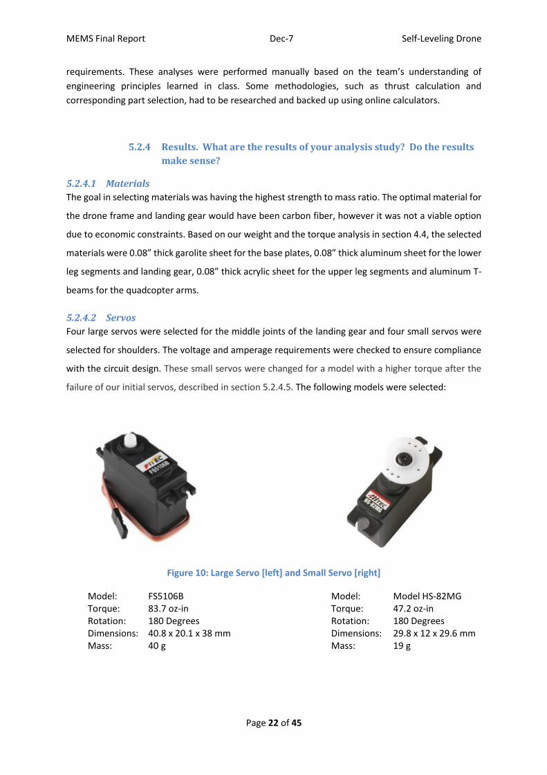
5.2.4.2 Servos
Four large servos were selected for the middle joints of the landing gear and four small servos were
selected for shoulders. The voltage and amperage requirements were checked to ensure compliance
with the circuit design. These small servos were changed for a model with a higher torque after the
failure of our initial servos, described in section 5.2.4.5. The following models were selected:
Figure 10: Large Servo [left] and Small Servo [right]
Model: FS5106B Model: Model HS-82MG Torque: 83.7 oz-in Torque: 47.2 oz-in Rotation: 180 Degrees Rotation: 180 Degrees Dimensions: 40.8 x 20.1 x 38 mm Dimensions: 29.8 x 12 x 29.6 mm Mass: 40 g Mass: 19 g
MEMS Final Report Dec-7 Self-Leveling Drone
Page 23 of 45
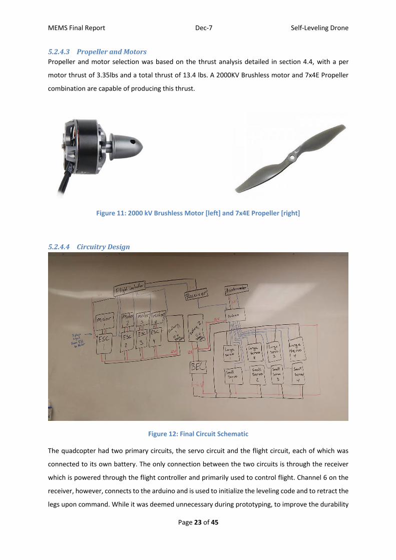
5.2.4.3 Propeller and Motors
Propeller and motor selection was based on the thrust analysis detailed in section 4.4, with a per
motor thrust of 3.35lbs and a total thrust of 13.4 lbs. A 2000KV Brushless motor and 7x4E Propeller
combination are capable of producing this thrust.
Figure 11: 2000 kV Brushless Motor [left] and 7x4E Propeller [right]
5.2.4.4 Circuitry Design
Figure 12: Final Circuit Schematic
The quadcopter had two primary circuits, the servo circuit and the flight circuit, each of which was
connected to its own battery. The only connection between the two circuits is through the receiver
which is powered through the flight controller and primarily used to control flight. Channel 6 on the
receiver, however, connects to the arduino and is used to initialize the leveling code and to retract the
legs upon command. While it was deemed unnecessary during prototyping, to improve the durability

MEMS Final Report Dec-7 Self-Leveling Drone
Page 24 of 45
of the design a common ground should be established by connecting the ground of each separate
circuit. A common ground would ensure that the signal transmitted by the receiver to the arduino is
high enough to be picked up by the arduino.
Servo Circuit:
Eight Servos were used to control the leveling gear, one small servo connected to the arms of the
quad-copter and one larger servo at the elbow joint of each leg. An Arduino Uno was used to filter and
analyze the data coming in from the accelerometer and control the servos accordingly. The
accelerometer, a triple axis MMA8452 accelerometer breakout board from Sparkfun, was used to
determine how far from level the quad-copter was. Unfortunately, the data received from the
accelerometer contained too much noise to be useful so a moving filter was placed on the incoming
data with a filter size of 15 data points.
MMA8452 Accelerometer Breakout Board:
The filtered accelerometer data was then used to move each pair of servos. Upon initialization of the
servo code each large servo moves 90 degrees and then each pair of servos continues to move
according to the data received by the accelerometer. The servos retract to their zeroed position when
the operator switches off channel 5 on the transmitter.
Early in our design it was assumed that the servos could only be controlled by the PWM (pulse width
modulation) pins on the arduino board, which, because an arduino uno only has 6 PWM pins,
necessitated a PWM shield. While servos are controlled by PWM signals, it was later discovered that
that they need not be controlled through PWM pins because the servo libraries native to arduino
produce the exact PWM signal needed to communicate with the servos. This greatly simplified the
circuit.
Flight control circuit:
The foundation of the flight control circuit is our Naze32 flight controller. This flight controller was
chosen for a number of reasons including its compatibility with Baseflight, the software we used to
program the flight controller. Our Naze32 included an accelerometer, a gyroscope and a barometer,
each used to sense and control the flight dynamics of our copter. The FC controlled each of the four
electronic speed controllers and received commands via the receiver.
5.2.4.5 Continued Analysis through Prototyping
MEMS Final Report Dec-7 Self-Leveling Drone
Page 25 of 45
5.2.5 Significance. How will the results influence the final prototype?
What dimensions and material choices will be affected?
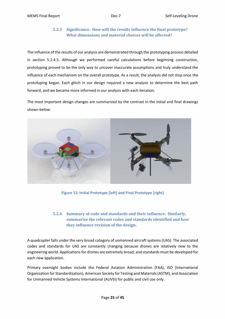
The influence of the results of our analysis are demonstrated through the prototyping process detailed
in section 5.2.4.5. Although we performed careful calculations before beginning construction,
prototyping proved to be the only way to uncover inaccurate assumptions and truly understand the
influence of each mechanism on the overall prototype. As a result, the analysis did not stop once the
prototyping began. Each glitch in our design required a new analysis to determine the best path
forward, and we became more informed in our analysis with each iteration.
The most important design changes are summarized by the contrast in the initial and final drawings
shown below:
Figure 13: Initial Prototype [left] and Final Prototype [right]
5.2.6 Summary of code and standards and their influence. Similarly,
summarize the relevant codes and standards identified and how
they influence revision of the design.
A quadcopter falls under the very broad category of unmanned aircraft systems (UAS). The associated
codes and standards for UAS are constantly changing because drones are relatively new to the
engineering world. Applications for drones are extremely broad, and standards must be developed for
each new application.
Primary oversight bodies include the Federal Aviation Administration (FAA), ISO (International
Organization for Standardization), American Society for Testing and Materials (ASTM), and Association
for Unmanned Vehicle Systems International (AUVSI) for public and civil use only.

MEMS Final Report Dec-7 Self-Leveling Drone
Page 26 of 45
The Federal Aviation Administration’s policy is separated into three categories: Public, Civil, and Model
Unmanned Aircraft, for which code and standards vary considerably. Our prototype is designed for
recreational and hobby use only, and is considered a model aircraft by FAA standards.
Statutory parameters of model aircraft operation put forth by the Federal Aviation Administration are
outlined in Section 336 of Public Law 112-95 (the FAA Modernization and Reform Act of 2012).
1) Aircraft flown strictly for hobby or recreational use;
2) The aircraft is operated in accordance with a community-based set of safety guidelines and
within the programming of a nationwide community-based organization;
3) The aircraft is limited to not more than 55 unless otherwise certified through a design,
construction, inspection, flight test, and operational safety program administered by a
community-based organization;
4) the aircraft is operated in a manner that does not interfere with and gives way to any manned
aircraft; and
5) when flown within 5 miles of an airport, the operator of the aircraft provides the airport
operator and the airport air traffic control tower (when an air traffic facility is located
at the airport) with prior notice of the operation (model aircraft operators flying from a
permanent location within 5 miles of an airport should establish a mutually-agreed upon
operating procedure with the airport operator and the airport air traffic control tower (when
an air traffic facility is located at the airport).
Where Model Aircraft is defined:
1) Capable of sustained flight in the atmosphere;
2) Flown within visual line of sight of the person operating the aircraft; and
3) Flown for hobby or recreational purposes.
These guidelines are detailed in advisory circular AC 91-57A- Model Aircraft Operating Standards.
Additional applicable guidelines include,
ASTM F3005 Standard Specification for Batteries for Use in Small Unmanned Aircraft Systems
ASTM F3003-14 Standard Specification for Quality Assurance of Small Unmanned Aircraft
System
ISO/TC 20/SC 16 – Unmanned Aircraft Systems (Still in development)
Academy of Model Aeronautics National Model Aircraft Safety Code
Given that our parts were purchased from well-established model aircraft suppliers, we did not
purchase specific standards related to things such as batteries and motors, assuming that the
distributer had ensured compliance. We did confirm, however, that our prototype falls within the
weight, size, and flight specifications of Unmanned Model Aircraft. The codes and standards outlined
above will most heavily impact our quad copter during flight. FAA regulations state simply that UAS
may not be flown in prohibited areas as determined by the private regulations in that location.
Washington University property permits model aircraft and will serve as our testing site.

MEMS Final Report Dec-7 Self-Leveling Drone
Page 27 of 45
5.3 Risk Assessment
5.3.1 Risk Identification
There is risk associated with the budget, schedule, operation, construction, and testing of our quad
copter. Risks associated with industry engineering projects such as market share or manufacturing
considerations are not applicable for the scope of this project.
Table 3 in section 5.3.2 identifies conditions under which the project will take place and associated
risks.
5.3.2 Risk Analysis
The risks identified in section 5.3.1 were discussed during the initial engineering analysis stage of our
project and efforts were made to mitigate them. Calculations were repeatedly checked in attempt
minimize errors, the CAD model was refined in order to streamline the machining process, and value
engineering was performed to ease budget concerns. Throughout the prototyping process, extensive
research was done before testing the electronics in order to avoid a malfunction. Potential events
resulting from these risks are listed in the third column and numbers for the resulting effects on the
project are listed in the fourth. Table 4 specifies these effects.

MEMS Final Report Dec-7 Self-Leveling Drone
Page 28 of 45
Table 3: Risk identification, corresponding events, and effects on project
Table 4: Potential effects specification for Table 3
5.3.3 Risk Prioritization
Our team recognized that our budget was adequate for the purpose of our design, and understood
that additional funds could be allocated in the event that we slightly surpassed the budget
Condition AssociatedRisk PotentialEvent
Potential
ProjectImpact Probability
Impact[1-low,5-high]
Finalprototypemustbecompletedbysemesterend 1)Partsunavailable
a)Partsdonotcomeinontimeb)Partmalfunctions 1 high 4
2)Schedulingconflictslimittime
thatengineerscandedicateto
prototyping
a)Engineerscannotmeetoften
enoughtocompleterequired
prototyping
b)Engineersrushthrough
prototyping 1,2 medium 3
Prototypemustbecompletedunderbudget 1)Costofpartsmiscalculated
a)Partmalfunctionsb)Incorrectpartselected 3 high 2
2)Allottedbudgetinadequatefor
designrequirements
a)Cornerscutindesignand
partselectionb)Designhaltedwhenbudget
reached 2 low 2
Prototypemustbeoperableby
user 1)UsernottrainedinUASflight
a)Usercannotutilizelevelinggearasintended
b)Usercrashesdrone 2,3,4 low 5
2)Heavywindconditions
a)Dronecannotbemanuvered
properly
b)Batterylifeshortened 2,4 low 1
3)Circuitjarredduringflight
a)Levelinggearcannotdeploy
b)Flightmechanismfailure
resultingincrash 2,3,4 medium 5
4)Dronelandsonroughterrain
a)Levelinggearcannotdeploy
b)Levelinggearorlandinggear
breaks 1,2,3 medium 3
Prototypemustmeetdesignspecifications
1)Designrequirementstooambituous
a)Additionalresearchandpracticebyengineersneeded 1 low 2
2)Gapinengineeringknowledgeofpartfunctionalityresultsin
incorrectpartselection
a)Newpartmustbeordered
b)Newpartmustbemachined 1,2,3,4 high 3
3)Miscalculationininitial
engineeringanalysis
a)Prototypeisnotproperly
machined
b)Newpartmustbeordered 1,2,3 high 3
Prototypemustbetested1)Levelinggearbreaksduringflighttesting
a)Levelinggearmustberemade,partsreordered 1,2,3 low 5
2)Flightmechanismbreaksduringtesting
a)Prototypecannotbefullydemonstratedb)Partsmustbereordered 1,2,3 low 4
PotentialEffectsSpecification1 Unabletocompletetheprototypeasdesignedbythedeadline2 Prototypedoesnotfunctionasdesired3 Unforseencostincreasepotentiallyresultinginprototypebeingoverbudget4 Injurymayoccurtouser/designer

MEMS Final Report Dec-7 Self-Leveling Drone
Page 29 of 45
requirements. Therefore, risks associated only with cost considerations were determined to be less
critical than those associated with scheduling and prototype performance. The most concerning risks
were those that could push back the schedule. Even if no setbacks occurred, our team would have
been hard pressed to produce a prototype that met our design specifications by the deadline. Some
of our electronic parts were specialized and required over a week to arrive, rendering the biggest risk
to our project.
Had our team reached the flight testing stages, the sensitive nature of the electronics associated with
the leveling gear would have posed the highest risk to our project. This risk was given particular
attention and a testing plan put in place to minimize it (as described in section 5.2.4.5).
The probability of the events associated with each risk is in column 5 of Table 3. Column 6 shows our
predicted income on the overall project success. A combination of these two metrics was used to
prioritize our risk mitigation efforts.

MEMS Final Report Dec-7 Self-Leveling Drone
Page 30 of 45
6 Working prototype
6.1 A preliminary demonstration of the working prototype (this section
may be left blank).
6.2 A final demonstration of the working prototype (this section may be
left blank).
6.3 At least two digital photographs showing the prototype
Figure 14: Initial Working Prototype
Figure 14 shows the initial working prototype. For the initial prototype we focused on the leveling
aspect of the drone. At this point in the process both of the joints on each leg rotate the same amount
to create a scissor like effect. After this initial prototype we opted to change this functionally to rotate
the bottom joint to 90 degrees then begin rotating the top joint. This was to reduce the amount of
drag that the “foot” would create on the ground. To accommodate this new motion we had to
lengthen the rigid landing gear legs and at this point we chose to modify the materials as well. We also
decided to modify the body shape from a square plate to a hexagonal plate in order to create more
room for the electronic components and to prevent the need for a second layer.

MEMS Final Report Dec-7 Self-Leveling Drone
Page 31 of 45
Figure 15: Final Working Prototype
This final working prototype shown in Figure 15 shows the completed quadcopter with a functioning
leveling gear as well as a completed flight system. Also pictured here is the new rigid landing gear,
made of aluminum rather than plastic rods, and the new hexagonal base plate, which is able to hold
all of the necessary electronics for both flight and leveling.
6.4 A short video clip that shows the final prototype performing
These video clips demonstrate the drone’s ability to zero and level automatically based on remote
user input. This partial leveling video depicts the drone leveling with use of a single leg on a slope of
approximately 15 degrees.
Zeroing Demo (https://www.youtube.com/watch?v=xkND9DpJPRA&feature=youtu.be)
Leveling Demo (https://www.youtube.com/watch?v=guKJOlmqntg&feature=youtu.be)
6.5 At least four (4) additional digital photographs and their explanations

MEMS Final Report Dec-7 Self-Leveling Drone
Page 32 of 45
Figure 16: Close up of the hinged landing gear joints
Figure 16 depicts the two leg joints used to level the drone. The joints are moved by servos which are
controlled by the arduino. The arduino takes input from the accelerometer and determines the
orientation of the drone. The arduino uses the information from the accelerometer to determine
which leg or legs to move to achieve a level orientation.

MEMS Final Report Dec-7 Self-Leveling Drone
Page 33 of 45
Figure 17: Accelerometer and Flight Controller
Figure 17 depicts the orientation of the accelerometer and the flight controller in relation to the body
of the drone. Note that the corners of the flight controller point in the axial directions, while the sides
of the accelerometer are oriented towards the axes.
Figure 18: Quad-copter at an approximately 15 degree angle during testing
MEMS Final Report Dec-7 Self-Leveling Drone
Page 34 of 45
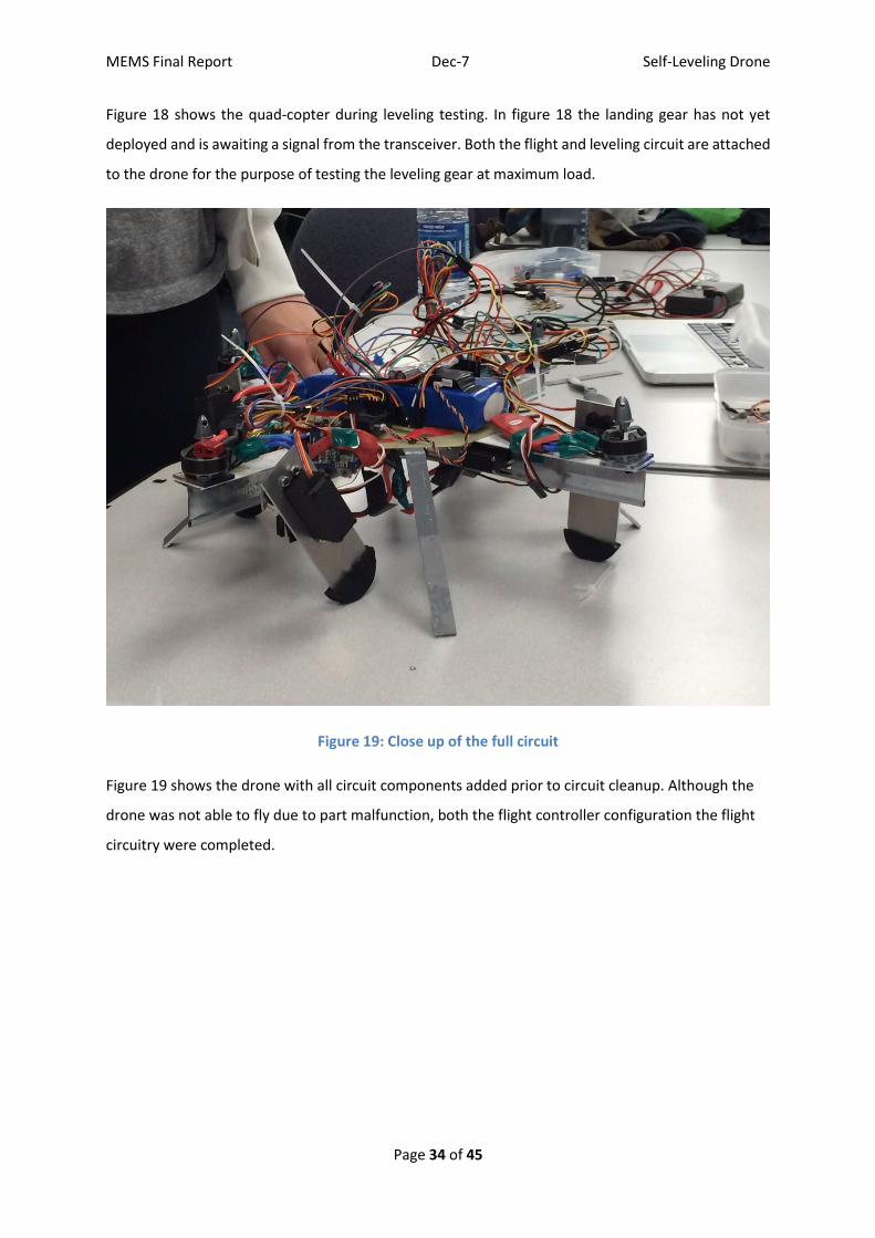
Figure 18 shows the quad-copter during leveling testing. In figure 18 the landing gear has not yet
deployed and is awaiting a signal from the transceiver. Both the flight and leveling circuit are attached
to the drone for the purpose of testing the leveling gear at maximum load.
Figure 19: Close up of the full circuit
Figure 19 shows the drone with all circuit components added prior to circuit cleanup. Although the
drone was not able to fly due to part malfunction, both the flight controller configuration the flight
circuitry were completed.

MEMS Final Report Dec-7 Self-Leveling Drone
Page 35 of 45
7 Design documentation
7.1 Final Drawings and Documentation
7.1.1 A set of engineering drawings that includes all CAD model files and
all drawings derived from CAD models.
Engineering drawings can be found under Appendix C. All CAD model files can be found
under the following link.
7.1.2 Sourcing instructions
The Bill of Materials can be found under Appendix B.
7.2 Final Presentation
7.3 Teardown
Figure 20: Teardown agreement

MEMS Final Report Dec-7 Self-Leveling Drone
Page 36 of 45
8 Discussion
8.1 Using the final prototype produced to obtain values for metrics,
evaluate the quantified needs equations for the design. How well were
the needs met?
Unfortunately, due to a number of part malfunctions, flight was never achieved. Therefore, the
drone’s ability to fly for five minutes remains untested. However, the completed drone weighed a
mere 3.4 lbs, well under the 5 lbs goal. Additionally, the landing gear was able to achieve accurate
leveling for up to a 20 degree angle and it did this consistently, through the transmitter and is capable
of leveling in approximately 5 seconds. The drone was proven to be able to level from any orientation
and the leveling gear can refold at any point via a command from the transmitter.
8.2 Discuss any significant parts sourcing issues?
For our parts we relied heavily on Sparkfun and Amazon. For the most part there were no
unreasonably long part delivery times, with the exception of a set of electronic speed controllers that
had to be reordered when they were lost in transit. Many of our parts were borrowed from ASME and
from friends, primarily things used for testing such as servo testers and battery chargers. It is highly
recommended for future projects that students be very aware of the connectors they will need for
electronic components. It is likewise beneficial to note that no high quality batteries can be ordered
online as it is technically illegal to ship them. Students needed LiPo batteries should start in electronic
stores nearby, such as MicroCenter.
8.3 Discuss the overall experience:
8.3.1 Was the project more of less difficult than you had expected?
As is always the case with any project, especially those with electronics, it is always harder than you
expect.
8.3.2 Does your final project result align with the project description?
Our final project aligns very well with the project description. We were able to fulfill the vast majority
of our quantified needs and created a product very similar to that which we imagined from the outset.
8.3.3 Did your team function well as a group?
MEMS Final Report Dec-7 Self-Leveling Drone
Page 37 of 45
Our team worked well together, even under pressure. We were able to communicate well and did a
fairly good job of splitting up tasks.
8.3.4 Were your team member’s skills complementary?
Most of the skills we used in this project we picked up over the course of the project. However,
because we specialized from the outset, we did end with complementary skills.
8.3.5 Did your team share the workload equally?
With some exceptions, our team did an excellent job of sharing the workload equally.
8.3.6 Was any needed skill missing from the group?
Because we started with very limited machining and programming skills and functionally no electronic
prototyping skills, many skills were missing from the group. However, these skills were developed over
the course of the project.
8.3.7 Did you have to consult with your customer during the process, or
did you work to the original design brief?
We did not consult with our customer during the process. We worked to the original design brief.
8.3.8 Did the design brief (as provided by the customer) seem to change
during the process?
There was little or no change to the design brief during the design process.
8.3.9 Has the project enhanced your design skills?
Many skills were developed that had never before been used, including CNC milling, much of the
programming, electronic prototyping, etc.
8.3.10 Would you now feel more comfortable accepting a design project
assignment at a job?
Having gone through this process, accepting a design project assignment at a job would be much
easier.

MEMS Final Report Dec-7 Self-Leveling Drone
Page 38 of 45
8.3.11 Are there projects that you would attempt now that you would not
attempt before?
There are a few projects that have been inspired by this one that we look forward to working on,
however, there are no projects we would not otherwise have attempted had we not gone through
this process.

MEMS Final Report Dec-7 Self-Leveling Drone
Page 39 of 45
9 Appendix A - Parts List
ITEM NO. PART DESCRIPTION QTY.
1 Base Plate 1
2 Landing Gear 4
4 Micro Servo 4
5 Micro Servo Horn 4
6 Quadcopter T-Arm 1
8 Upper Leg 4
9 Lower Leg 4
10 Standard Servo 4
11 Standard Servo Horn 4
12 Motors 1
13 Propeller 4
14 3000mAh Batteries 1
15 Electronic Speed Controllers
1
16 DSMX Receiver 1
17 Servo Controller 1
10 Appendix B - Bill of Materials PART USE VENDOR MODEL
NUMBER QUANTITY UNIT
PRICE TOTAL PRICE
Aluminum T-Beam Arms Home Depot
N/A 4 $2.00 $8.00
Acrylic Sheet Base Plate and Legs
Home Depot
N/A 2 $3.50 $7.00
Aluminum Sheet Landing Gear and Legs
Amazon B003JKJET6 1 $19.10 $19.10
Rubber thread Leg Traction MEMS Machine Shop
N/A 4 sq. inches
$0 $0.00
Arduino Uno Rev 3 Flight/Servo Control
Sparkfun LC-066 1 $24.95 $24.95
PWM Shield Servo Control Sparkfun BOB-10616 ROHS
1 $19.95 $19.95
BEC Power Distribution/Reduction
Dimension Engineering
SportBEC 2 $29.95 $59.90
Servo High Torque Leg Stabilization SparkFun ROB-11965 RoHS
4 $12.95 $51.80
Servo Sub Micro Leg Stabilization Sparkffun ROB-09065 RoHS
4 $8.95 $35.80

MEMS Final Report Dec-7 Self-Leveling Drone
Page 40 of 45
Buffered 3D Accelerometer
Leveling Sparkfun SEN-12756 RoHS
1 $9.95 $9.95
ESC Motors/Flight Amazon B013G4XR92 4 18 $72.00
3000 mAh Lithium Polymer Battery
Energy Amazon B00HWQ4OLG
2 $19.99 $39.98
2000 kV Brushless Motor
Motors/Flight Amazon B00ZP84OA4 4 $13.25 $53.00
Emax Skyline32 Flight Controller
Flight Controller Amazon B014WCFEN4 1 $37.99 $37.99
Receiver Flight/Servo Control
Amazon B004M166WE 1 $70 $70.00
Additional Circuitry Leg Stabilization Micro Center
N/A 1 $27 $27
Servo Micro Leg Stabilization Amazon B0012YXRJE 4 $20 $80
Propellers Flight APC 7x4E 12 $2.45 $29.40
Total $645.82
11 Appendix C - CAD Models
Figure 21: Drone Assembly

MEMS Final Report Dec-7 Self-Leveling Drone
Page 41 of 45
Figure 22: Base Plate
Figure 23: T-Arm

MEMS Final Report Dec-7 Self-Leveling Drone
Page 42 of 45
Figure 24: Landing Gear
Figure 25: Lower Leg

MEMS Final Report Dec-7 Self-Leveling Drone
Page 43 of 45
Figure 26: Upper Leg

MEMS Final Report Dec-7 Self-Leveling Drone
Page 44 of 45
12 Annotated Bibliography [1] U.S. Department of Defense. "Robotic Landing Gear Could Enable Future Helicopters to Take Off and Land Almost Anywhere." DARPA RSS. Defense Advanced Research Projects Agency, 9 Oct. 2015. Web. 07 Dec. 2015. A detailed description of DARPA’s ongoing attempts to design self-leveling landing gear for
helicopters. [2] Rippere, Tony. "An Approach to Designing Passive Self-leveling Landing Gear with Application to the Lunar Lander." NASA Archive (n.d.): n. pag. NASA. This article details the creation of NASA's self-leveling landing gear for their Lunar Rover. Though
relatively different in application, the qualified needs for NASA's design closely mirror those developed for our project.
[3]"Static Thrust Calculation." AirWolf 2. Quadcopterproject, 12 Sept. 2011. 06 Dec. 2015.
An online static thrust calculator used to verify our thrust calculations.
[4]Dickey, J. "Static Thrust Calculation." Quadcopterproject. Aircraft World, 12 Sept. 2011. Web. 07 Dec. 2015.
Used to determine static thrust calculations.
[5] Federal Aviation Administration. "Model Aircraft Operations." Model Aircraft Operations. US Department of Transportation, n.d. Web. 07 Dec. 2015. A description of federal regulations regarding the use of unmanned aerial vehicles for recreational
purposes.

MEMS Final Report Dec-7 Self-Leveling Drone
Page 45 of 45