Embed Size (px)
Citation preview

n Memory capacity upgraded! Four times or eight times as large as base model of 64 M-words lets you record differing electric potential objects simultaneously
n Isolated inputs for all channels enhance measurement safety Record differing electric potential objects simultaneouslyn Sturdy construction designed for use in the field Tough body and strong enclosure provide superior resistance to shocks, falls, and vibrations.
Clears a 50 cm drop test. Note: Using in-house testing conditions. Absence of impairment or damage in all cases is not assured.
n High-speed printing for checking data right on the spot Printer features newly designed roll paper drop-in loading and one-touch setup, along with high
50 mm/s printing speed.n FFT analysis and other functions FFT, waveform calculation and memory segmentation functionality. Input units support pulse integration, frequency, and direct current sensor connections.
Recorders
Upgraded Multi-Purpose Memory Recorder
MR8847-01MR8847-02MR8847-03MEMORY HiCORDER
Fully Isolated, High Speed & Tough for the Field

22
The Ideal Recorder for Field UseFeatures Easy Portability and Sturdy Construction
Select the memory capacity according to your needs - Full Line-up of 64WW, 256MW or 512MW models

3
No Delay
3
n A problem occurs, requiring immediate attention on site Grab the sturdy handle and go. The tough construction can
take a few knocks.
n Start measurement without reading through the manual The Help Wizard assists you to do exactly what you want.
n Print out results on the spot Load printer paper with a simple one-touch operation. High printing speed gives you a hard copy in a snap.
High Speed n High-speed sampling up to 20 MS/s Full isolation for all channels and simultaneous sampling
n Save 30MB to a CF Card: Max. 40 seconds Data save speed may vary, depending on conditions.
n High speed FFT calculation
X-Y Operation
n Multi-channel X-Y recorder with electronic data log
n Simultaneous recording over 16 analog + 16 logic channels
n Simultaneous recording over 64 logic + 10 analog channels Plug-in modules provide the flexibility to match most
channel and signal configuration requirements.
Computer Integration
n Easy storage of recorded data USB memory stick / CF card / internal hard disk
n HTTP/FTP server function and remote operation capability provide easy access to data
n 20 MS/s High-speed waveform judgment function
n For maintenance, production line monitoring or pre-shipment inspections
4
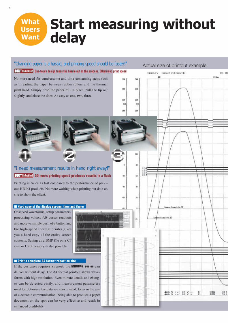
One-touch design takes the hassle out of the process. 50mm/sec print speed
Start measuring without delay
No more need for cumbersome and time-consuming steps such as threading the paper between rubber rollers and the thermal print head. Simply drop the paper roll in place, pull the tip out slightly, and close the door. As easy as one, two, three.
What Users Want
No Problem!
Actual size of printout example
n Print a complete A4 format report on siteIf the customer requires a report, the MR8847 series can deliver without delay. The A4 format printout shows wave-forms with high resolution. Even minute details and chang-es can be detected easily, and measurement parameters used for obtaining the data are also printed. Even in the age of electronic communication, being able to produce a paper document on the spot can be very effective and result in enhanced credibility.
n Hard copy of the display screen, then and there
Observed waveforms, setup parameters, processing values, AB cursor readouts and more--a simple push of a button and the high-speed thermal printer gives you a hard copy of the entire screen contents. Saving as a BMP file on a CF card or USB memory is also possible.
Printing is twice as fast compared to the performance of previ-ous HIOKI products. No more waiting when printing out data on site to show the client.
"I need measurement results in hand right away!"50 mm/s printing speed produces results in a flashNo Problem!
"Changing paper is a hassle, and printing speed should be faster!"

5
What Users Want
Monitor high-speed signals
High-speed 20 MS/s sampling provides ample margin
The operation principle is the same as for a digital oscilloscope: data are stored at high speed in the high-capacity internal memory. Even with all channels operating simultaneously, sampling rates up to 20 mega-samples per second (50 ns cycle) are possible. This ensures that sudden event spikes and instantaneous waveform changes are captured reliably.
n Semiconductor memory storageUnits using hard disks or other mechanical media for storage are vulnerable to vibrations and therefore not ideal for automotive measurement and similar applications. By saving data in semiconductor based memory without any mechanical drive parts, the MEMORY HiCORDER is much more suited to such applications. Simply back up the data later to a CF card or USB memory stick, and you're done.
No Problem!
"1 MS/s is too slow for observing fast pulse edges"
MR8847-01 (64MW)
MR8847-03 (512MW)
Input
Input
Input
Input
A/Dconversion
A/Dconversion
Write to memory
Write to memory
Inpu
t vol
tage
Minimum 50 nsec (Maximum sampling speed 20 MS/s)
A/D conversion
A/Dconversion
Insulation
Insulation
Insulation
Insulation
Screen displayPrint out
Screen displayPrint out
4 or 8 times the base memory of 64MW also available
The MR8847-01 has the same 64MW capacity as the previous Model 8847, while the MR8847-02 and MR8847-03 offer 4 and 8 times the memory, respec-tively.
n Long term recording to internal memory devices with high-speed accessData sampled at 20MS/s moves too fast to be stored in general memory devices such as a CF card or hard disk, prompting HIOKI to develop a proprietary system that combines our own FPGA device with high-speed access memory. Now you can record long term, high speed waveform data at ease.
No Problem!
"I need a larger memory"
High-speed waveform judgment function
Pass or fail measured waveforms with the wave comparison function.
n Enchanced speed, functionality and certaintyTaking advantage of the advanced performance of the MR8847 series such as 20MS/s sampling and multi-channel array to make quick deci-sions on captured waveforms, ideal for urgent maintenance applications where clear pass/fail determinations need to be made.
n Make close to real-time decisionsWhen using a time-axis range slower than 100msec/div, measured wave-forms can be compared in near real-time, enabling you to detect failures on the spot. Production can be halted in time to minimize resource waste.
No Problem!
"I need compare normal and abnormal waveforms." Compare captured waveform with reference area
n USB mouse enabledConveniently edit the reference area using a mouse. Waveforms can be drawn on a PC in BMP format and imported to the HiCORDER.
New
New
New

6
n Pen up/down controlIndividual pen up/down control is possible during X-Y recording, not only by using the Function but-tons but also via external signals at the EXT. IN1, 2, 3 connectors.
Having an X-Y recorder would be handy!
What Users Want
Chart-type X-Y recorders are disappearing from the market, but they had certain advantages that are sometimes desirable. The MR8847 series brings them back with features such as independent pen up/down control. Because data are stored as a time-based series, electronic storage can be applied to tasks for which paper archives used to be necessary.
"An X-Y recorder uses paper, but electronic data would be better !"X-Y recorder with electronic recordingNo Problem!
The MR8847 series comes standard with 16 logic input channels. Three more logic input modules with up to 48 logic channels can be installed in place of analog input modules, resulting in simultaneous recording capacity for up to 64 channels in total. All channels can be displayed on a single screen, which is ideal for timing measurements. Furthermore, simultaneous recording of analog waveforms is possible in up to 10 channels.
"There are scores of relays, and I need to measure the timing of them all!"Max. 64 channels Logic input + 10 channels Analog inputNo Problem!
EXT. IN 1EXT. IN 2EXT. IN 3
n Waveform comparison during X-Y recordingWaveform comparison can be done not only in the time domain waveform, but also in the X-Y domain waveform. The X-Y waveforms captured from these and many other applications can be tested against reference waveforms automatically:
• Alteration and pressure at press machines• Pump pressure and flow
New

7
HUB
n Waveform observation/CSV conversion software bundled as standard (Wv)
l Binary data collected with the HiCORDER can be observed as waveforms on a computer.
l Data can be converted to CSV format for importing into Excel.
The software is supplied free of charge with the product, and the latest version can also be downloaded from the HIOKI web site.
Wv screen sample
EXCEL sheet sample
What Users Want
Analyze data on a computer
Measurement data can be saved on any generic USB memory device. Automatic data saving is also available, making it more convenient to transfer data to a PC.Caution: Although USB memory sticks enable automatic data saving, for more reliable data protection, we recommend use of HIOKI CF cards, which are guar-anteed to work with the instrument.
"I want to use a USB memory stick!"Compatible to USB memory sticksNo Problem!
A 100BASE-TX LAN port is built in as standard equipment.
<HTTP server capability> Access the unit via a web browser run-ning on a computer, for waveform observation and remote opera-tion. Waveform data of the MR8847 series can also be download-ed and pasted onto Excel.
<FTP server capability> Copy the memory contents of the MR8847 series (internal RAM, CF card, HDD) to a computer.
"I want to hook up to a LAN!"LAN port and HTTP/FTP server functionNo Problem!
USB receptacle AUSB receptacle BLAN terminal
The B type connector can be used to connect the MR8847 series to a PC for remote operation. When a USB memory stick is not easily accessible, the internal data of the MR8847 series can be sent to the PC via this USB terminal.
"I want to connect to a PC via USB"Communicate with a PC via a USB connectionNo Problem!
New
8
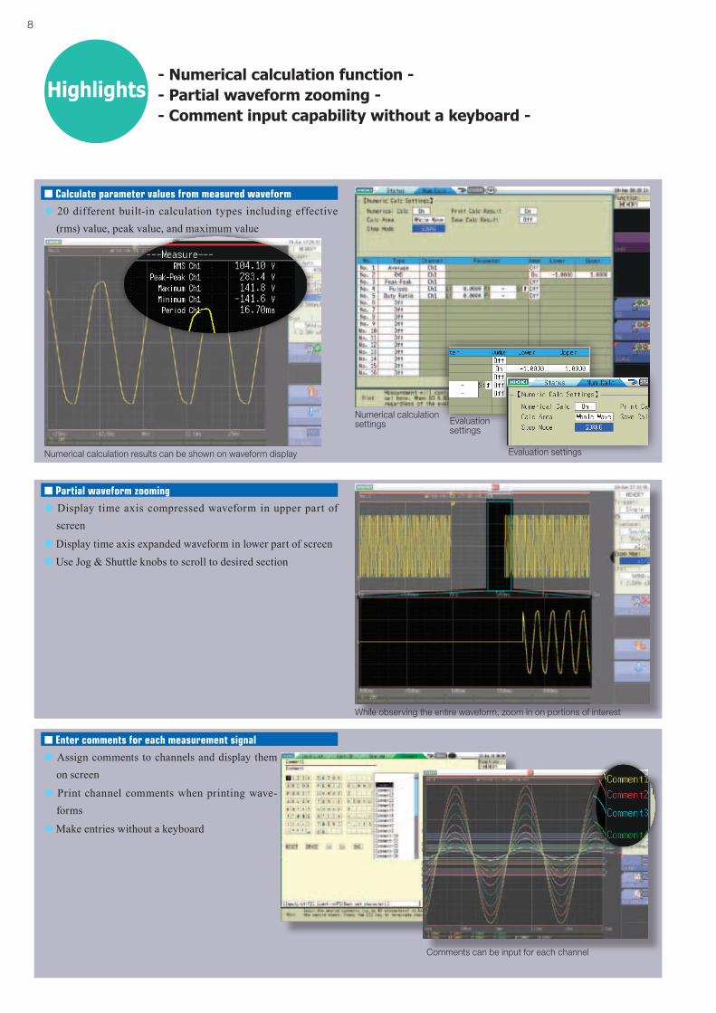
- Numerical calculation function -- Partial waveform zooming -- Comment input capability without a keyboard -
Numerical calculation results can be shown on waveform display
Numerical calculation settings Evaluation
settings
Evaluation settings
While observing the entire waveform, zoom in on portions of interest
Comments can be input for each channel
n Calculate parameter values from measured waveform
l 20 different built-in calculation types including effective (rms) value, peak value, and maximum value
Highlights
n Partial waveform zooming
l Display time axis compressed waveform in upper part of screen
l Display time axis expanded waveform in lower part of screenl Use Jog & Shuttle knobs to scroll to desired section
n Enter comments for each measurement signal
l Assign comments to channels and display them on screen
l Print channel comments when printing wave-forms
l Make entries without a keyboard

9
Input
Input
A/D
A/D
Insulation
Screen display
Maximum Value
Minimum Value
Recording Speed
RECtime axis Sampling period To internal memory
20,000 divisions
Continuous (approx. recording time with one 30m paper roll) Note: Calculated as 30 m = 2,970 divisions Changing paper enables permanent continuation of recording
100 ms/div
1 μs, 10 μs, 100 μs,1 ms, 10 ms, 100 ms
Note: Limited by combination
of selections under 1/100 on
time axis and time axis setting
for memory recording
33 min 20 s Display only200 ms/div 1 h 6 min 40 s Display only500 ms/div 2 h 46 min 40 s 24 min 45 s
1 s/div 5 h 33 min 20 s 49 min 30 s2 s/div 11 h 6 min 40 s 1 h 39 min 00 s5 s/div 1 d 3 h 46 min 40 s 4 h 7 min 30 s
10 s/div 2 d 7 h 33 min 20 s 8 h 15 min 00 s30 s/div 6 d 22 h 40 min 00 s 24 h 45 min 00 s50 s/div 11 d 13 h 46 min 40 s 1 d 17 h 15 min 00 s
100 s/div 23 d 3 h 33 min 20 s 3 d 10 h 30 min 00 s1 min/div 13 d 21 h 20 min 00 s 2 d 1 h 30 min 00 s2 min/div 27 d 18 h 40 min 00 s 4 d 3 h 00 min 00 s5 min/div 69 d 10 h 40 min 00 s 10 d 7 h 30 min 00 s
10 min/div 138 d 21 h 20 min 00 s 20 d 15 h 00 min 00 s30min/div 416 d 16 h 00 min 00 s 61 d 21 h 00 min 00 s
1 hr/div 833 d 8 h 00 min 00 s 123 d 18 h 00 min 00 s
- Simultaneous recording on recording media -- Chart recording reliably captures noise events -
n Chart recording reliably captures noise events (Recorder function)
l High-speed sampling ensures that noise events are captured also with slow recordingl Data compression achieved by recording maximum/minimum value pairsl Up to 833 days (1 hour/division) of recording time on the MR8847-01 (64 M-Words memory)
l Chart output enables permanent recordingNote: When opening data created with the Recorder function on a computer, the maximum and minimum data
pairs are lined up in a time series.Note: Length of printer paper roll is 30 meters. Paper can be changed during operation without stopping the
recording process.
Write tomemory
Recording on chart
n Maximum recording times with Recorder functionNote: With settings between 100 ms and 200 ms/div on the time axis, continuous recording is not possible if printer is ON.Note: The table below shows values for the MR8847-01 (64 M-words memory capacity). Model MR8847-02 (256 MW) is
four times, Model MR8847-03 (512 MW) is eight times of the MR8847-01. At ''Continuous'' setting in recording length, cannot increase total recording time.
Highlights Memory function
Recorder function
n Simultaneous recording on storage media (Memory function)
l Automatic data saving on HDD / CF card or USB memory stickl During high-speed sampling, data are written to internal RAM first
and later saved on other medial During low-speed sampling, data are written to internal RAM and
sequentially saved on other mediaNote: At 100 ms/division or slower, using near real-time save onto storage media
l Highly suitable for long-term recordingCaution: Available recording duration is determined by internal RAM capacity, not by external media.Caution: Although USB memory sticks enable automatic data saving, for more reliable data protection,
we recommend use of HIOKI CF cards, which are guaranteed to work with the instrument.
Inp
ut v
olta
ge
Sampling period Time
Write to media
Input
A/D conversion
A/D conversion
Write to memory
Input
n Extracts from max. recording times into internal memory (Memory function)Note: The table below shows the maximum value at arbitrary recording length settingsNote: Saving to media in near real-time is possible at sampling speeds of 100 ms/div (1 ms sampling) or
slower
MR8847-01 (64MW)
MR8847-02 (256MW)
MR8847-03 (512MW)
Maximum recording time increases depending on
number of channels usedAnalog 16 ch
+ internal Logic 16 chAnalog 16 ch
+ internal Logic 16 chAnalog 16 ch
+ internal Logic 16 ch
Time axis Samplingperiod 40,000 div 160,000 div 320,000 div
5μs/div 50ns 0.2s 0.8s 1.6s
10μs/div 100ns 0.4s 1.6s 3.2s
100μs/div 1μs 4s 16s 32s
1ms/div 10μs 40s 2min 40s 5min 20s
100ms/div 1ms 1h 06min 40s 4h 26min 40s 8h 53min 20s
1s/div 10ms 11h 06min 40s 1d 20h 26min 40s 3d 16h 53min 20s
1min/div 600ms 27d 18h 40min 00s 111d 02h 40min 00s 222d 05h 20min 00s
5min/div 3.0s 138d 21h 20min 00s 555d 13h 20min 00s 1111d 02h 40min 00s
10
1,000 points
Convert 1,000 to 10,000 points
Before scaling
After scaling
n Recalculate by changing the number of calculation points after measurementEven for measurement data currently based on a lower number of calculation points, it is possible to increase the number later and perform analysis again. For example, data measured at a setting of 1,000 points can be converted and reanalyzed with a 10,000 point setting. This will result in a tenfold increase in frequency analysis resolution. Of course, the opposite is also possible, going for exam-ple from 10,000 points to 1,000 points.Note: Recalculation with a different number of calculation points is not possible if frequency
averaging is set to ON.
n Decibel-based scalingDecibel-based scaling as requested by numerous customers is now possible. There is no more need to make logarithmic conversions on the side with an electronic calculator. The MR8847 series can accept input of overall values (power spectrum sum) in dB, with the capability for easy scaling. Signals from noise level meters and similar equipment can therefore be read directly.
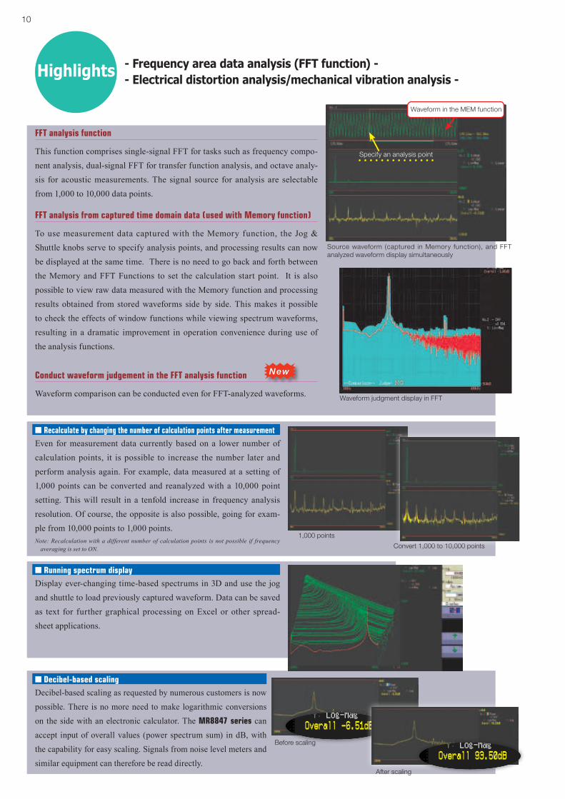
- Frequency area data analysis (FFT function) -- Electrical distortion analysis/mechanical vibration analysis -Highlights
This function comprises single-signal FFT for tasks such as frequency compo-nent analysis, dual-signal FFT for transfer function analysis, and octave analy-sis for acoustic measurements. The signal source for analysis are selectable from 1,000 to 10,000 data points.
FFT analysis function
To use measurement data captured with the Memory function, the Jog & Shuttle knobs serve to specify analysis points, and processing results can now be displayed at the same time. There is no need to go back and forth between the Memory and FFT Functions to set the calculation start point. It is also possible to view raw data measured with the Memory function and processing results obtained from stored waveforms side by side. This makes it possible to check the effects of window functions while viewing spectrum waveforms, resulting in a dramatic improvement in operation convenience during use of the analysis functions.
FFT analysis from captured time domain data (used with Memory function)
Specify an analysis point
n Running spectrum displayDisplay ever-changing time-based spectrums in 3D and use the jog and shuttle to load previously captured waveform. Data can be saved as text for further graphical processing on Excel or other spread-sheet applications.
Waveform in the MEM function
Source waveform (captured in Memory function), and FFT analyzed waveform display simultaneously
Waveform judgment display in FFTWaveform comparison can be conducted even for FFT-analyzed waveforms.
Conduct waveform judgement in the FFT analysis function New

11
Measure a variety of signals in one goFind problem solutions straight away
Power facilities
Generating stations
Transformer stations
Steel and chemical plants
Short-circuit/interruption
testing
Facilities diagnosis
Troubleshooting
Motors
Railways/Transport
Automotive
Development and testing
Fault and problem analy-
sis
Quality control
Elevators
Machine tools and hy-
draulic machinery
Production facilities
Maintenance
Troubleshooting
Performance and charac-
teristics testing
nApplication example Load interruption test at generator
n Use pre-trigger function to record waveform before and after interruption
n Test breaker characteristicsn Use multiple isolated input channels simultaneouslyn Instantly load paper and print out full-width waveform
nApplication example Commercial power supply line mea-surement
n Use drop trigger to monitor voltage dropsn Evaluate waveform when switching to UPS or other sourcen Use instantaneous waveform recording for 50/60 Hzn Isolated inputs eliminate short-circuiting risks
nApplication example Railway carriage problem analysis
n Use pre-trigger function to record instantaneous waveform before and after problem
n Check notch curves and cam progression waveformn Use logic probe to record cam contact point signal waveformn Record MG startup current waveform using clamp sensor
nApplication example Motor startup current measurement
n Observe correlation between main motor current waveform and relay signal
n Long term recording time; with the MR8847-01 up to 3min 20sec at 1ms/div range, and the MR8847-03 up to 26min 40sec.
n Make simultaneous current and voltage measurements using multiple channels and isolated inputs
n Use trigger wait function to pinpoint and record problem waveforms only
nApplication example Measurement of hydraulic machinery operation waveform
n Perform braking mechanism measurementn Perform X-Y measurement of valve flow and pressuren Perform X-Y measurement of load and displacementn Use pen up/down and playback functions
nApplication example Check for bearing wear and deterio-ration
n Perform FFT analysis over a frequency range from DC to 8 MHz
n Perform long-term signal recording and analyze only re-quired parts
n Use FFT analysis to diagnose cracks and similar problems

12
MEMORY (high-speed recording)
Time axis
5 μs to 5 min/div (100 samples/div) 26 ranges, External sampling (100 samples/div, or free setting),
Time axis zoom: ×2 to ×10 in 3 stages, compression: 1/2 to 1/20,000 in 13 stages
Sampling period 1/100 of time axis range (minimum 50 ns period)
Recording length
MR8847-01: 16 ch mode: 25 - 20,000 div, 2 ch mode: 25 - 200,000 div (built-in presets) or arbitrary setting in 1-div steps (max. 320,000 div)
MR8847-02: 16 ch mode: 25 - 100,000 div, 2 ch mode: 25 - 1,000,000 div (built-in presets) or arbitrary setting in 1-div steps (max. 1,280,000 div)
MR8847-03: 16 ch mode: 25 - 200,000 div, 2 ch mode: 25 - 2,000,000 div (built-in presets) or arbitrary setting in 1-div steps (max. 2,560,000 div)
Pre-trigger Record data from before the trigger point at 0 to +100% or -95% of the recording length in 15 stages, or in 1 div step settings
Numerical calculation
• Simultaneous calculation for up to 16 selected channels Average value, effective (rms) value, peak to peak value, maximum value, time to maximum value, minimum value, time to minimum value, period, frequency, rise time, fall time, standard deviation, area value, X-Y area value, specified level time, specified time level, pulse width, duty ratio, pulse count, four arithmetic operations, Time difference, phase difference, high-level and low-level
• Calculation result evaluation output: GO/NG (with open-collector 5 V output)
• Automatic storing of calculation results
Waveform processing
For up to 16 freely selectable channels, the following functions can be performed (results are automatically stored):
Four arithmetic operations, absolute value, exponentiation, common logarithm, square root, moving average, differentiation (primary, secondary), integration (primary, secondary), parallel displacement along time axis, trigonometric functions, reverse trigonometric func-tions
Memory segmentation • Max. 1024 blocks, sequential storage, multi-block storage
Other functions
• No logging• X-Y waveform synthesis (1-screen, 4-screens)• Overlay (always overlay when started/overlay only required waveforms)• Automatic/ Manual/ A-B cursor range printing/ Report printing
RECORDER (real-time recording)
Time axis
10 ms to 1 hour/div, 19 ranges, time axis resolution 100 points/divNote: Out of data acquired at selected sampling rate, only maximum and minimum value data determined using 100 points/div units are stored
Time axis compression selectable in 13 steps, from × 1/2 to × 1/20,000
Sampling rate 1/10/100 µs 1/10/100 ms (selectable from 1/100 or less of time axis)
Real-time printing
Supported* Real-time printing is possible at time axis settings slower than 500 ms/div* Delayed print is performed when recording length is not set to ‘‘Continuous’’ and time axis setting is 10 ms - 200 ms/div
* When recording length is set to ‘‘Continuous’’ and time axis setting is 10 ms - 200 ms/div, manual printing can be performed after measurement stop
Recording length
MR8847-01: Built-in presets of 25 - 20,000 div, or ‘‘Continuous’’ or arbitrary setting in 1-div steps (max. 20,000 div)
MR8847-02: Built-in presets of 25 - 50,000 div, or ‘‘Continuous’’ or arbitrary setting in 1-div steps (max. 80,000 div)
MR8847-03: Built-in presets of 25 - 100,000 div, or ‘‘Continuous’’ or arbitrary setting in 1-div steps (max. 160,000 div)
Additional recording Supported (recording is resumed without overwriting previous data)
Waveform memory
MR8847-01: Store data for most recent 20,000 div in memoryMR8847-02: Store data for most recent 80,000 div in memoryMR8847-03: Store data for most recent 160,000 div in memoryNote: Backward scrolling and re-printing available
Auto save Data are automatically saved on CF card, USB memory stick or internal HDD after measurement stops
Other functions • No logging• Manual/ A-B cursor range printing/ Report printing
X-Y RECORDER (X-Y real-time recording)
Sampling period 1/10/100 ms (dot), 10/100 ms (line)
Recording length Continuous
Screen, Printing Split screen (1 or 4), Manual printing only
Number of X-Y 1 to 8 phenomenon
X-Y channel setting Any 8 channels out of 16 can be selected for X axis and Y axis respectively
X-Y axis resolution 25 dots/div (screen), horizontal 80 dots/div × vertical 80 dots/div (printer)
Waveform memory Sampling data for last 4,000,000 points are stored in memory
Pen up/down Simultaneous for all phenomena
External pen control Possible via external input connector (simultaneous up/down for all phenomena)
Internal PrinterFeatures Printer paper one-touch loading, high-speed thermal printing
Recording paper216 mm (8.50 in) × 30 m (98.43 ft), thermal paper roll (use 9231 paper) Recording witdh: 200 mm (7.87 in) 20 division full scale, 1 div = 10 mm (0.39 in) 80 dots
Recording speed Max. 50 mm (1.97 in)/sec
Paper feed density 10 lines/mm
Display
Display 10.4 inch SVGA-TFT color LCD (800 × 600 dots)(Time axis 25 div × Voltage axis 20 div, X-Y 20 div × 20 div)
Languages English, Japanese, Korean, Chinese
Waveform display zoom/compression
Time axis: ×10 to ×2 (zoom at MEMORY function only), ×1, ×1/2 to ×1/20,000, Voltage axis: ×100 to ×2, ×1, ×1/2 to ×1/10
Variable display Upper/Lower limit set, display/div set
Scaling 10:1 to 1000:1, automatic scaling for various probesManual scaling (conversion ratio setting, 2-point setting, unit setting)
Comment input Alphanumeric input (title, analog and logic channels)Simple input, history input, phrase input
Logic waveform Display point move 1 % step, Line width 3 types
Display partition Max. Eight divisions
Monitor function Input level monitorNumerical value (Sampling 10kS/s fixed, refresh rate 0.5s)
Other display functions
• Waveform inversion (positive/negative)• Cursor measurement (A, B, 2-cursor, for all channels)• Vernier function (amplitude fine adjustment)• Zoom function (horizontal screen division, zoomed waveform shown in lower section)
• 16 selectable colors for waveform display• Zero position shift in 1% steps for analog waveform• Global zero adjust for all channels and all ranges
Basic specifications (product guaranteed for one year)
Measurement functions
MEMORY (high-speed recording)RECORDER (real-time recording)X-Y RECORDER (X-Y real-time recording)FFT (frequency analysis)
Number of input units
[8 analog input modules]: 16 analog channels + 16 logic channels (stan-dard)
[5 analog input modules + 3 logic input modules]: 10 analog channels + 64 logic channels (standard 16 channels + 48 channels in logic input modules)
* For analog units, channels are isolated form each other and from frame GND.
For logic units and internal standard logic terminals, all channels has com-mon GND.
Maximum sampling rate
20 MS/second (50 ns period, all channels simultaneously)External sampling (10 MS/second, 100 ns period)
Internal memory
MR8847-01: Total 64 M-words (Memory expansion: none) 32 MW/ch (using 2 Analog channels), to 4 MW/ch (using 16 Analog channels)MR8847-02: Total 256 M-words (Memory expansion: none) 128 MW/ch (using 2 Analog channels), to 16 MW/ch (using 16 Analog channels)MR8847-03: Total 512 M-words (Memory expansion: none) 256 MW/ch (using 2 Analog channels), to 32 MW/ch (using 16 Analog channels)Note: 1 word = 2 bytes (12-bits or 16-bits), therefore 64 Mega-word = 128 Mega-bytes.Note: Internal memory is allocated depending on the number of channels used.
Data storage media*2 Factory installation only
CF card slot (standard) ×1 (up to 2GB, FAT, or FAT-32 format)Hard disk drive ×1 (80 GB, optional Model 9664 *2)USB memory stick (USB 2.0)
n Main unit Specifications
Backup functions(At 25°C/ 77°F)
Clock and parameter setting backup: at least 10 yearsWaveform backup function: none
External control connectors
Terminal block: External trigger input, Trigger output, External sampling input, Two external outputs (GO/NG output), Three external inputs (start, stop, print input)
External interfacesLAN: 100BASE-TX (DHCP, DNS supported, FTP server, HTTP server)USB: USB2.0 compliant, series A receptacle ×1, series B receptacle ×1, (File transfer HDD/ CF card to PC, or remort control from PC)
Environmental conditions(No condensation)
Operation: -10°C (14°F) to 40°C (104°F), 20 % to 80 % rhPrinter use: 0°C (32°F) to 40°C (104°F), 20 % to 80 % rhHD use: 5°C (41°F) to 40°C (104°F), 20 % to 80 % rhStorage: -20°C (-4°F) to 50°C (122°F), 90 % rh or less
Compliance standard Safety: EN61010, EMC: EN61326, EN61000-3-2, EN61000-3-3
Power supply 100 to 240 V AC, 50/60 Hz10 to 28 V DC (use the DC POWER UNIT 9784 : Factory installation only)
Power consumption 130 VA max. (Printer not used), 220 VA max. (Printer used)
Dimensions and mass
Approx. 351 mm (13.82 in) W × 261 mm (10.28 in) H × 140 mm (5.51 in) D, 7.6 kg (268.1 oz) (main unit only)
Supplied accessories
Instruction Manual ×1, Measurement Guide ×1, Application Disk (Wave Viewer Wv, Communication Commands table) ×1, Power cord ×1, Input cord label ×1, USB cable ×1, Printer paper ×1, Roll paper attachment ×2

13
Trigger functions
Trigger mode MEMORY (high-speed recording), FFT: Single, Repeat, AutoRECORDER (real-time recording): Single, Repeat
Trigger sources
CH1 to CH16 (analog), Standard Logic 16ch + Logic Unit (Max. 3 units 48 channels), External (a rise of 2.5V or terminal short circuit), Timer, Manual (either ON or OFF for each source),
Logical AND/OR of sources
Trigger types
• Level: Triggering occurs when preset voltage level is crossed (upwards or downwards)
• Voltage drop: Triggering occurs when voltage drops below peak voltage setting (for 50/60 Hz AC power lines only)
• Window: Triggering occurs when window defined by upper and lower limit is entered or exited
• Period: Rising edge or falling edge cycle of preset voltage value is monitored and triggering occurs when defined cycle range is exceeded
• Glitch: Triggering occurs when pulse width from rising or falling edge of preset voltage value is under run
• Event setting: Event count is performed for each source, and triggering occurs when a preset count is exceeded
• Logic: 1, 0, or ×, Pattern setting
Level setting resolution 0.1% of full scale (full scale = 20 divisions)
Trigger filter Selectable 0.1div to 10.0div, or OFF (at MEMORY function)ON (10ms fixed) or OFF (at RECORDER function)
Trigger output
Open collector (5 voltage output, active Low)At Level setting: pulse width (Sampling period × data number after trigger)
At Pulse setting: pulse width (2ms)
Other functions
Trigger priority (OFF/ON), Pre-trigger function for capturing data from before / after trigger event (at MEMORY function), Level display during trigger standby, Start and stop trigger (At RECORDER function), Trigger search function
FFT function
Analysis mode
Storage waveform, Linear spectrum, RMS spectrum, Power spectrum, Density of power spectrum, Cross power spectrum,
Auto-correlation function, Histogram, Transfer function, Cross-correlation function, Impulse response, Coherence function,
1/1 Octave analysis, 1/3 Octave analysis, LPC analysis, Phase spectrum
Analysis channels Selectable from all analog input channels
Frequency range 133 mHz to 8 MHz, External, (resolution 1/400, 1/800, 1/2000, 1/4000)
Number of sampling points 1000, 2000, 5000, 10000 points
Window functions Rectangular, Hanning, Hamming, Blackman, Blackman-Harris, Flat-top, Exponential
Display format Single, Dual, Nyquist, Running spectrum
Averaging functionTime axis / frequency axis simple averaging, Exponential averaging, Peak hold (frequency axis),
Averaging times: 2 times to 10,000 times
Print functions Same as the MEMORY function (partial print not available)
Other functions
Waveform judgment function(In MEMORY or FFT function)
• Area comparison with reference waveform area for time domain waveform, X-Y waveform, or FFT analysis waveform
• Parameter calculated value comparison with reference value• Output: GO/NG decision, Open-collector 5V, Note: Judge waveforms in near real-time at samplings speeds of 100msec/div (1ms sampling) or slower.
Measurement target With use input unit Measurement range Resolution
Voltage
ANALOG UNIT 8966 100mV f.s. - 400V f.s. 50µV
HIGH RESOLUTION UNIT 8968
100mV f.s. - 400V f.s. 3.125µV
DC/RMS UNIT 8972 100mV f.s. - 400V f.s. 50µV
CurrentCURRENT UNIT 8971 + optional current sensor
20A f.s. or largerWhen driving current sensors with separate power supply, measurement can be conducted with voltage input units.
1mA or larger
RMS AC voltage
DC/RMS UNIT 8972 100mV f.s. - 400V f.s. 50µV
Temperature(Thermocouple input)
TEMP UNIT 8967
200°C f.s. to 2000°C f.s. Note: Upper and lower limit values depend on the thermocouple
0.01°C
Frequency, rotation
FREQ UNIT 8970
20 Hz f.s. - 100 kHz f.s.2 (kr/min) f.s. - 2000 (kr/min) f.s.
2mHz0.2(r/min)
Power frequency
FREQ UNIT 8970
40 - 60 Hz, 50 - 70 Hz, 390 - 410 Hz 0.01Hz
Pulse add up
FREQ UNIT 8970
40k-counts f.s. - 20M-counts f.s. 1 count
Pulse duty ratio
FREQ UNIT 8970 100% f.s. 0.01%
Pulse width
FREQ UNIT 8970 0.01s f.s. - 2s f.s. 1µs
Vibration, Stress
STRAIN UNIT 8969 400µe f.s. - 20000µe f.s. 0.016µe
Relay contacts, voltage on/off
LOGIC UNIT 8973 — —
nMeasurement Indices (Optional input unit types)
MR8847-01 (64MW) MR8847-02 (256MW) MR8847-03 (512MW)Maximum recording time increases depending on
number of channels used
Analog 16 ch+ internal Logic 16 ch
Analog 2 ch+ internal Logic 16 ch
Analog 16 ch+ internal Logic 16 ch
Analog 2 ch+ internal Logic 16 ch
Analog 16 ch+ internal Logic 16 ch
Analog 2 ch+ internal Logic 16 ch
Time axis Sampling period 40,000 div 320,000 div 160,000 div 1,280,000 div 320,000 div 2,560,000 div
5μs/div 50ns 0.2s 1.6s 0.8s 6.4s 1.6s 12.8s
10μs/div 100ns 0.4s 3.2s 1.6s 12.8s 3.2s 25.6s
20μs/div 200ns 0.8s 6.4s 3.2s 25.6s 6.4s 51.2s
50μs/div 500ns 2s 16s 8s 1min 04s 16s 2min 08s
100μs/div 1μs 4s 32s 16s 2min 08s 32s 4min 16s
200μs/div 2μs 8s 1min 04s 32s 4min 16s 1min 04s 8min 32s
500μs/div 5μs 20s 2min 40s 1min 20s 10min 40s 2min 40s 21min 20s
1ms/div 10μs 40s 5min 20s 2min 40s 21min 20s 5min 20s 42min 40s
2ms/div 20μs 1min 20s 10min 40s 5min 20s 42min 40s 10min 40s 1h 25min 20s
5ms/div 50μs 3min 20s 26min 40s 13min 20s 1h 46min 40s 26min 40s 3h 33min 20s
10ms/div 100μs 6min 40s 53min 20s 26min 40s 3h 33min 20s 53min 20s 7h 06min 40s
20ms/div 200μs 13min 20s 1h 46min 40s 53min 20s 7h 06min 40s 1h 46min 40s 14h 13min 20s
50ms/div 500μs 33min 20s 4h 26min 40s 2h 13min 20s 17h 46min 40s 4h 26min 40s 35h 33min 20s
100ms/div 1ms 1h 06min 40s 8h 53min 20s 4h 26min 40s 1d 11h 33min 20s 8h 53min 20s 2d 23h 06min 40s
200ms/div 2ms 2h 13min 20s 17h 46min 40s 8h 53min 20s 2d 23h 06min 40s 17h 46min 40s 5d 22h 13min 20s
500ms/div 5ms 5h 33min 20s 1d 20h 26min 40s 22h 13min 20s 7d 09h 46min 40s 44h 26min 40s 14d 19h 33min 20s
1s/div 10ms 11h 06min 40s 3d 16h 53min 20s 1d 20h 26min 40s 14d 19h 33min 20s 3d 16h 53min 20s 29d 15h 06min 40s
2s/div 20ms 22h 13min 20s 7d 09h 46min 40s 3d 16h 53min 20s 29d 15h 06min 40s 7d 09h 46min 40s 59d 06h 13min 20s
5s/div 50ms 2d 07h 33min 20s 18d 12h 26min 40s 9d 06h 13min 20s 74d 01h 46min 40s 18d 12h 26min 40s 148d 03h 33min 20s
10s/div 100ms 4d 15h 06min 40s 37d 00h 53min 20s 18d 12h 06min 40s 148d 03h 33min 20s 37d 00h 53min 20s 296d 07h 06min 40s
30s/div 300ms 13d 21h 20min 00s 111d 02h 40min 00s 55d 13h 20min 00s 444d 10h 40min 00s 111d 02h 40min 00s 888d 21h 20min 00s
50s/div 500ms 23d 03h 33min 20s 185d 04h 26min 40s 92d 14h 13min 20s 740d 17h 46min 40s 185d 04h 26min 40s 1481d 11h 33min 20s
1min/div 600ms 27d 18h 40min 00s 222d 05h 20min 00s 111d 02h 40min 00s 888d 21h 20min 00s 222d 05h 20min 00s 1777d 18h 40min 00s
100s/div 1.0s 46d 07h 06min 40s 370d 08h 53min 20s 185d 04h 26min 40s 1481d 11h 33min 20s 370d 08h 53min 20s 2962d 23h 06min 40s
2min/div 1.2s 55d 13h 20min 00s 444d 10h 40min 00s 222d 05h 20min 00s 1777d 18h 40min 00s 444d 10h 40min 00s 3555d 13h 20min 00s
5min/div 3.0s 138d 21h 20min 00s 1111d 02h 40min 00s 555d 13h 20min 00s 4444d 10h 40min 00s 1111d 02h 40min 00s 8888d 21h 20min 00s
nMaximum Recording Time for the internal memory (At MEMORY Function)
Note: The above table is maximum value at arbitrary recording length settings.Note: Saving to media in near real-time is possible at sampling speeds of 100ms/div (1msec sampling) or slower.Note: Operation cannot be guaranteed for extended recording periods one year or longer. The above table represents theoretical
values.
Note: Each unit has two input channels.Note: Besides logic units (16 channels), The MR8847 series comes stan-
dard with 16 logic inputs integrated in the device.

14
n Options specifications (sold separately, for the MR8847 series only)
ANALOG UNIT 8966 (Accuracy at 23 ±5 °C/73 ±9 °F, 20 to 80 % rh after 30 minutes of warm-up time and zero adjustment; accuracy guaranteed for 1 year)
Measurement functions Number of channels: 2, for voltage measurement
Input connectorsIsolated BNC connector (input impedance 1 MΩ, input capacitance 30 pF), Max. rated voltage to earth: 300 V AC, DC (with input isolated from the
unit, the maximum voltage that can be applied between input channel and chassis and between input channels without damage)
Measurement range5 mV to 20 V/div, 12 ranges, full scale: 20 div, AC voltage for possible measurement/display using the memory function: 280 V rms,
Low-pass filter: 5/50/500 Hz, 5 k/50 k/500 kHzMeasurement resolution
1/100 of measurement range (using 12-bit A/D conversion and when installed in the 8847)
Highest sampling rate 20 MS/s (simultaneous sampling across 2 channels)
Measurement accuracy ±0.5 % of full scale (with filter 5 Hz, zero position accuracy included)
Frequency characteristics DC to 5 MHz -3 dB, (with AC coupling: 7 Hz to 5 MHz -3dB)
Input coupling AC/DC/GND
Max. allowable input 400 V DC (the maximum voltage that can be applied across input pins without damage)
Dimensions and mass: approx. 106 (4.17in) W × 19.8 (0.78in) H × 196.5 (7.74in) D mm, approx. 250 g (8.8 oz) Accessories: None
TEMP UNIT 8967 (Accuracy at 23 ±5 °C/73 ±9 °F, 20 to 80 % rh after 30 minutes of warm-up time and zero adjustment; accuracy guaranteed for 1 year)
Measurement functions
Number of channels: 2, for temperature measurement with thermocouple (voltage measurement not available)
Input connectors
Thermocouple input: plug-in connector, Recommended wire diameter: single-wire, 0.14 to 1.5 mm2, braided wire 0.14 to 1.0 mm2 (conductor wire diameter min. 0.18 mm), AWG 26 to 16
Input impedance: min. 5 MΩ (with line fault detection ON/OFF), Max. rated voltage to earth: 300 V AC, DC (with input isolated from the unit, the maximum voltage that can be applied between
input channel and chassis and between input channels without damage)
Temperature measurement rangeNote: Upper and lower limit values depend on the thermocouple
10 °C/div (-100 °C to 200 °C), 50 °C/div (-200 °C to 1000 °C), 100 °C/div (-200 °C to 2000 °C), 3 ranges, full scale: 20 div,
Measurement resolution: 1/1000 of measurement range (using 16-bit A/D conversion and when installed in the 8847)
Thermocouple range(JIS C 1602-1995)(ASTM E-988-96)
K: -200 to 1350 °C, J: -200 to 1100 °C, E: -200 to 800 °C, T: -200 to 400 °C, N: -200 to 1300 °C, R: 0 to 1700 °C, S: 0 to 1700 °C, B: 400 to 1800 °C, W (WRe5-26): 0 to 2000 °C,
Reference junction compensation: internal/ external (switchable), Line fault detection ON/OFF possible
Data refresh rate 3 methods, Fast: 1.2 ms (digital filter OFF), Normal: 100 ms (digital filter 50/60 Hz), Slow: 500 ms (digital filter 10Hz)
Measurement accuracy
Thermocouple K, J, E, T, N: ±0.1 % of full scale ±1 °C (±0.1 % of full scale ±2 °C at -200 °C to 0 °C),
Thermocouple R, S, W: ±0.1 % of full scale ±3.5 °C (at 0 °C to 400 °C or less), ±0.1 % of full scale ±3 °C (at 400 °C or more)
Thermocouple B: ±0.1 % of full scale ±3 °C (at 400 °C or more), Reference junction compensation accuracy: ±1.5 °C (added to measurement accuracy
with internal reference junction compensation)
Dimensions and mass: approx. 106 (4.17in) W × 19.8 (0.78in) H × 204.5 (8.05in) D mm, approx. 240 g (8.5 oz) Accessories: Ferrite clamp × 2
HIGH RESOLUTION UNIT 8968 (Accuracy at 23 ±5 °C/73 ±9 °F, 20 to 80 % rh after 30 minutes of warm-up time and zero adjustment; accuracy guaranteed for 1 year)
Measurement functions Number of channels: 2, for voltage measurement
Input connectorsIsolated BNC connector (input impedance 1 MΩ, input capacitance 30 pF), Max. rated voltage to earth: 300 V AC, DC (with input isolated from the
unit, the maximum voltage that can be applied between input channel and chassis and between input channels without damage)
Measurement range5 mV to 20 V/div, 12 ranges, full scale: 20 div, AC voltage for possible measurement/display using the memory function: 280 V rms,
Low-pass filter: 5/50/500 Hz, 5k/50k Hz
Anti-aliasing filter Integrated filter for suppressing aliasing distortion caused by FFT processing (automatic cutoff frequency setting/OFF)
Measurement resolution 1/1600 of measurement range (using 16-bit A/D conversion and when installed in the 8847)
Highest sampling rate 1 MS/s (simultaneous sampling across 2 channels)
Measurement accuracy ±0.3 % of full scale (with filter 5 Hz, zero position accuracy included)
Frequency characteristics DC to 100 kHz -3 dB, (with AC coupling: 7 Hz to 100 kHz -3dB)
Input coupling AC/DC/GNDMax. allowable input 400 V DC (the maximum voltage that can be applied across input pins without damage)
Dimensions and mass: approx. 106 (4.17in) W × 19.8 (0.78in) H × 196.5 (7.74in) D mm, approx. 250 g (8.8 oz) Accessories: None
STRAIN UNIT 8969 (Accuracy at 23 ±5 °C/73 ±9 °F, 20 to 80 % rh after 30 minutes of warm-up time and auto-balance; accuracy guaranteed for 1 year)
Measurement functions
Number of channels: 2, for distortion measurement (electronic auto-balancing, balance adjustment range within ±10000 με)
Input connectors
Weidmuller SL 3.5/7/90G (via Conversion Cable 9769, TAJIMI PRC03-12A10-7M10.5)
Max. rated voltage to earth: 33 Vrms or 70 V DC (with input isolated from the unit, the maximum voltage that can be applied between input channel and chassis and between input channels without damage)
Suitable transducer Strain gauge converter, Bridge impedance: 120 Ω to 1 kΩ, Bridge voltage: 2 V ±0.05 V, Gauge rate: 2.0
Measurement range 20 με to 1000 με/div, 6 ranges, full scale: 20 division, Low-pass filter: 5/10/100 Hz, 1 kHz
Measurement resolution
1/1250 of measurement range (using 16-bit A/D conversion and when installed in the 8847)
Highest sampling rate 200 kS/s (simultaneous sampling across 2 channels)
Measurement accuracy ±(0.5 % of full scale +4 με) (at 5 Hz filter ON, After auto-balancing)
Frequency characteristics DC to 20 kHz +1/-3dB
Dimensions and mass: approx. 106 (4.17in) W × 19.8 (0.78in) H × 196.5 (7.74in) D mm, approx. 220 g (7.8 oz) Accessories: Conversion cable 9769 × 2 (cable length 50 cm/1.64 ft)
FREQ UNIT 8970 (Accuracy at 23 ±5 °C/73 ±9 °F, 20 to 80 % rh after 30 minutes of warm-up time; accuracy guaranteed for 1 year)
Measurement functions
Number of channels: 2, for voltage input based frequency measurement, rotation, power frequency, integration, pulse duty ratio, pulse width
Input connectors
Isolated BNC connector (input impedance 1 MΩ, input capacitance 30 pF), Max. rated voltage to earth: 300 V AC, DC (with input isolated from the
unit, the maximum voltage that can be applied between input channel and chassis and between input channels without damage)
Frequency modeRange: Between DC to 100kHz (minimum pulse width 2μs), 1Hz/div to 5kHz/div (full scale= 20 div), 8 settings
Accuracy: ±0.1% f.s. (exclude 5kHz/div), ±0.7% f.s. (at 5kHz/div)
Rotation mode
Range: Between 0 to 2 million rotations/minute (minimum pulse width 2μs), 100 (r/min)/div to 100k (r/min)/div (full scale= 20 div), 7 settings
Accuracy: ±0.1% f.s. (excluding 100k (r/min)/div), ±0.7% f.s. (at 100k (r/min)/div)
Power frequency mode
Range: 50Hz (40 - 60Hz), 60Hz (50 - 70Hz), 400Hz (390 - 410Hz) (full scale= 20 div), 3 settings
Accuracy: ±0.03Hz (exclude 400Hz range), ±0.1Hz (400Hz range)
Integration mode Range: 2k counts/div to 1M counts/div, 6 settingsAccuracy: ±range/2000
Duty ratio modeRange: Between 10Hz to 100kHz (minimum pulse width 2μs), 5%/div (full
scale=20 div)Accuracy: ±1% (10Hz to 10kHz), ±4% (10kHz to 100kHz)
Pulse width mode Range: Between 2μs to 2sec, 500μs/div to 100ms/dv (full scale=20 div)Accuracy: ±0.1% f.s.
Measurement resolution
1/2000 of range (Integration mode), 1/500 of range (exclude integration, power frequency mode), 1/100 of range (power frequency mode)
Input voltage range and threshold level
±10V to ±400V, 6 settings, selectable threshold level at each range
Other functionsSlope, Level, Hold, Smoothing, Low-pass filter, Switchable DC/AC input coupling, Frequency dividing, Integration over-range keep/return
Dimensions and mass: approx. 106 (4.17in) W × 19.8 (0.78in) H × 196.5 (7.74in) D mm, approx. 250 g (8.8 oz) Accessories: None
CURRENT UNIT 8971 (Accuracy at 23 ±5 °C/73 ±9 °F, 20 to 80 % rh after 30 minutes of warm-up time and zero adjustment; accuracy guaranteed for 1 year)
Measurement functions
Number of channels: 2, Current measurement with optional current sensor, Maximum 4 units connectable to the 8847
Input connectors Sensor connector (input impedance 1 MΩ, exclusive connector for current sensor via conversion cable the 9318, common ground with recorder)
Compatible current sensors
CT6863, CT6862, 9709, 9279, 9278, 9277, 9272-10 (To connect the 8971 via conversion cable the 9318)
Measurement range
Using 9272-10 (20A), 9277: 100mA to 5A/div (f.s.=20div, 6 settings)Using CT6862: 200mA to 10A/div (f.s.=20div, 6 settings)Using 9272-10 (200A), 9278, CT6863: 1A to 50A/div (f.s.=20div, 6 settings)Using 9279, 9709: 2A to 100A/div (f.s.=20div, 6 settings)
Accuracy
Using 9278, 9279: ±0.85% f.s.Using other sensor: ±0.65% f.s.RMS amplitude accuracy: ±1% f.s. (DC, 30Hz to 1kHz), ±3% f.s. (1kHz to
10kHz)RMS response time: 100ms (rise time from 0 to 90% of full scale), Crest factor: 2
Frequency characteristics: DC to 100kHz, ±3dB (with AC coupling: 7Hz to 100kHz)
Measurement resolution 1/100 of rangeHighest sampling rate 1 MS/s (simultaneous sampling across 2 channels)
Other functions Input coupling: AC/DC/GND, Low-pass filter: 5, 50, 500, 5k, 50kHz, or OFF
Dimensions and mass: approx. 106 (4.17in) W × 19.8 (0.78in) H × 196.5 (7.74in) D mm, approx. 250 g (8.8 oz) Accessories: CONVERSION CABLE 9318 × 2 (To connect the current sensor to the 8971)

15
DC/RMS UNIT 8972 (Accuracy at 23 ±5 °C/73 ±9 °F, 20 to 80 % rh after 30 minutes of warm-up time and zero adjustment; accuracy guaranteed for 1 year)
Measurement functions Number of channels: 2, for voltage measurement, DC/RMS selectable
Input connectorsIsolated BNC connector (input impedance 1 MΩ, input capacitance 30 pF), Max. rated voltage to earth: 300 V AC, DC (with input isolated from the
unit, the maximum voltage that can be applied between input channel and chassis and between input channels without damage)
Measurement range5 mV to 20 V/div, 12 ranges, full scale: 20 div, AC voltage for possible measurement/display using the memory function: 280 V rms,
Low-pass filter: 5/50/500 Hz, 5 k/100 kHzMeasurement resolution 1/100 of measurement range (using 12-bit A/D conversion and when installed in 8847)
Highest sampling rate 1 MS/s (simultaneous sampling across 2 channels)
Measurement accuracy ±0.5 % of full scale (with filter 5 Hz, zero position accuracy included)
RMS measurement
RMS amplitude accuracy: ±1 % of full scale (DC, 30 Hz to 1 kHz), ±3 % of full scale (1 kHz to 100 kHz),
Response time: SLOW 5 s (rise time from 0 to 90% of full scale), MID 800 ms (rise time from 0 to 90% of full scale), FAST 100 ms (rise time from 0 to 90% of full scale), Crest factor: 2
Frequency characteristics DC to 400 kHz -3 dB, (with AC coupling: 7 Hz to 400 kHz -3dB)
Input coupling AC/DC/GNDMax. allowable input 400 V DC (the maximum voltage that can be applied across input pins without damage)
Dimensions and mass: approx. 106 (4.17in) W × 19.8 (0.78in) H × 196.5 (7.74in) D mm, approx. 250 g (8.8 oz) Accessories: None
LOGIC UNIT 8973Measurement functions Number of channels: 16 channels (4 ch/1 probe connector × 4 connectors)
Input connectors Mini DIN connector (for HIOKI logic probes only), Compatible logic probes: 9320-01, 9327, 9321-01
Dimensions and mass: approx. 106 (4.17in) W × 19.8 (0.78in) H × 196.5 (7.74in) D mm, approx. 190 g (6.7 oz) Accessories: None
n Options specifications (sold separately)
Dimensions and mass: approx. 290 (11.42in) W × 29 (1.14in) H × 219.5 (8.64in) D mm, approx. 1.2 kg (42.3 oz) Accessories: None
DC POWER UNIT 9784Rated input voltage 10 to 28 V DCPower requirements 200 VA (printer used)
Note: Factory-installed option, build in on the rear of the main unit
DC power supply module integrated on rear panel
LOGIC PROBE MR9321-01(Accuracy at 23 ±5°C/73 ±9°F, 35 to 80% rh, accuracy / product
guaranteed for 1 year)
Function Detection of AC or DC relay drive signal for High/Low state recordingCan also be used for power line interruption detection
Input 4 channels (isolated between unit and channels), HIGH/LOW range switchingInput resistance: 100 kΩ or higher (HIGH range), 30 kΩ or higher (LOW range)
Output (H) detection 170 to 250 V AC, ±DC 70 to 250 V (HIGH range)60 to 150 V AC, ±DC 20 to 150 V (LOW range)
Output (L) detection 0 to 30 V AC, ±DC 0 to 43 V (HIGH range)0 to 10 V AC, ±DC 0 to 15 V (LOW range)
Response time Rising edge 1 ms max., falling edge 3 ms max. (with HIGH range at 200 V DC, LOW range at 100 V DC)
Max. allowable input 250 Vrms (HIGH range), 150 Vrms (LOW range) (the maximum voltage that can be applied across input pins without damage)
Cable length and mass: Main unit cable 1.5 m (4.92 ft), input section cable 1 m (3.28 ft), approx. 320 g (11.3 oz)
Note: The unit-side plug of the MR9321-01 is different from the MR9321.
n PC Software Specifications Bundled with the MR8847s in the CD-R
Wave Viewer (Wv) Software
Functions
• Simple display of waveform file • Text conversion: convert binary data file to text format, with selectable space or tab separators in addition to CSV, and specifiable section, thinning available
• Display format settings: scroll functions, enlarge/reduce display, display channel settings
• Others: voltage value trace function, jump to cursor/trigger position function
Operating environment Windows 8/7 (32-bit/64-bit), Vista (32-bit), XP, 2000
WAVE PROCESSOR 9335Distribution media One CD-ROperating environment Running under Windows 8/7 (32-bit/64-bit), Vista (32-bit), XP, 2000
Display functionsWaveform display, X-Y display, Digital value display, Cursor function, Scroll function, Maximum number of channels (32 channels analog, 32 channels logic), Gauge display (time, voltage axes), Graphical display
File loadingReadable data formats (.MEM, .REC, .RMS, .POW)Maximum loadable file size: Maximum file size that can be saved by a given device (file size may be limited depending on the computer configuration)
Data conversionConversion to CSV format, Tab delimited/Space delimited Data culling (simple), Convert for specified channel, Batch conversion of multiple files
Print functionsPrint formatting (1 up, 2-to-16 up, 2-to-16 rows, X-Y 1-to-4 up), Preview, Hard copy functions usable on any printer supported by operating system
Other Parameter calculation, Search, Clipboard copy, Launching of other applications
Data analysis on the computernFeatures Waveform display, data calculation, printing
function
Cable length and mass: Main unit cable 1.5 m (4.92 ft), input section cable 30 cm (0.98 ft), approx. 150 g (5.3 oz)
Note: The unit-side plug of the 9320-01 is different from the 9320.
LOGIC PROBE 9320-01/9327 (Accuracy at 23 ±5°C/73 ±9°F, 35 to 80% rh, accuracy / product guaranteed for 1 year)
Function Detection of voltage signal or relay contact signal for High/Low state recording
Input
4 channels (common ground between unit and channels), digital/contact input, switchable (contact input can detect open-collector signals)
Input resistance: 1 MΩ (with digital input, 0 to +5 V) 500 kΩ or more (with digital input, +5 to +50V)Pull-up resistance: 2 kΩ (contact input: internally pulled up to +5 V)
Digital input threshold 1.4V/ 2.5V/ 4.0V
Contact input detection resistance
1.4 V: 1.5 kΩ or higher (open) and 500 Ω or lower (short)2.5 V: 3.5 kΩ or higher (open) and 1.5 kΩ or lower (short)4.0 V: 25 kΩ or higher (open) and 8 kΩ or lower (short)
Response speed 9320-01: 500ns or lower, 9327: detectable pulse width 100ns or higher
Max. allowable input 0 to +50V DC (the maximum voltage that can be applied across input pins without damage)
Cable length and mass: Main unit cable 1.3 m (4.27 ft), input section cable 46 cm (1.51 ft), approx. 350 g (12.3 oz)
DIFFERENTIAL PROBE 9322 (Accuracy at 23 ±5 °C/73 ±9 °F, 35 to 80 % rh after 30 minutes of warm-up time, accuracy / product guaranteed for 1 year)
Functions For high-voltage floating measurement, power line surge noise detection, RMS rectified output measurement
DC mode
For waveform monitor output, Frequency characteristics: DC to 10 MHz (±3 dB), Amplitude accuracy: ±1 % of full scale (at max. 1000 V DC), ±3% of full scale (at max. 2000 V DC) (full scale: 2000 V DC)
AC mode For detection of power line surge noise, Frequency characteristics: 1 kHz to 10 MHz ±3 dB
RMS mode
DC/AC voltage RMS output detection, Frequency characteristics: DC, 40 Hz to 100 kHz, Response speed: 200 ms or less (400 V AC), accuracy: ±1 % of full scale
(DC, 40 Hz to 1 kHz), ±4 % of full scale (1 kHz to 100 kHz) (full scale: 1000 V AC)
Input
Input type: balanced differential input, Input impedance/capacitance: H-L 9 MΩ/10 pF, H/L-unit 4.5 MΩ/20 pF, Max. rated voltage to earth: when using grabber clip 1500V AC/DC (CAT II), 600 V AC/DC (CAT III), when using alligator clip: 1000 V AC/DC (CAT II), 600 V AC/DC (CAT III)
Max. allowable input 2000 V DC, 1000 V AC (CAT II), 600 V AC/DC (CAT III)
Output Voltage divider for 1/1000 of input, BNC connectors (output switchable for 3 modes DC, AC, RMS)
Power source(1) Connect the AC ADAPTER 9418-15 or (2) Connect to HiCORDER logic terminal via the POWER CORD 9324 and CONVERSION CABLE 9323
HEADQUARTERS: 81 Koizumi, Ueda, Nagano, 386-1192, Japan TEL +81-268-28-0562 FAX +81-268-28-0568 http://www.hioki.com / E-mail: [email protected]
HIOKI USA CORPORATION: TEL +1-609-409-9109 FAX +1-609-409-9108 http://www.hiokiusa.com / E-mail: [email protected]
All information correct as of Feb. 5, 2014. All specifications are subject to change without notice. MR8847sE5-42B-00K Printed in Japan
DISTRIBUTED BYHIOKI (Shanghai) SALES & TRADING CO., LTD.: TEL +86-21-63910090 FAX +86-21-63910360 http://www.hioki.cn / E-mail: [email protected]
HIOKI INDIA PRIVATE LIMITED: TEL +91-124-6590210 FAX +91-124-6460113 E-mail: [email protected]
HIOKI SINGAPORE PTE. LTD.: TEL +65-6634-7677 FAX +65-6634-7477 E-mail: [email protected]
HIOKI KOREA CO., LTD.: TEL +82-42-936-1281 FAX +82-42-936-1284 E-mail: [email protected]
Note: Company names and Product names appearing in this catalog are trademarks or registered trademarks of various companies.
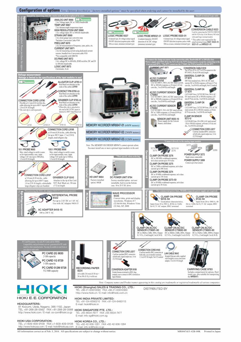
MEMORY HiCORDER MR8847-01 (64MW memory)
MEMORY HiCORDER MR8847-02 (256MW memory)
MEMORY HiCORDER MR8847-03 (512MW memory)
Note: The MEMORY HiCORDER MR8847s cannot operate alone. You must install one or more optional input modules in the unit.
Logic signal measurem
ent
LOGIC PROBE 9320-01 4-channel type, for voltage/contact signal ON/OFF detection (response pulse width 500 ns or more, miniature terminal type)
LOGIC PROBE MR9321-01 4 isolated channels, ON/OFF detection of AC/DC voltage (miniature terminal type)
LOGIC PROBE 9327 4-channel type, for voltage/contact signal ON/OFF detection (response pulse width 100 ns or more, miniature terminal type)
CONVERSION CABLE 9323 Used for connecting the 9320/9321/MR9321 and the 9324 relay to the Memory HiCorder with small logic terminal models
* This cable is not required for the small-terminal types 9327, 9320-01, 9321-01 and MR9321-01.
Recommended Recommended
Small terminal type only
ANALOG UNIT 8966 2 ch, Voltage input, DC to 5 MHz bandwidthTEMP UNIT 8967 2 ch, thermocouple temperature inputHIGH RESOLUTION UNIT 8968 2 ch, voltage input, DC to 100 kHz bandwidthSTRAIN UNIT 8969 2 ch, strain gauge type converter amp *Includes Conversion Cable 9769FREQ UNIT 8970 2 ch, for measurement of frequency, rpm, pulse, etc.CURRENT UNIT 8971 2 ch, for measuring current using dedicated current
sensors, bundled two Conversion cable 9318 *Not compatible with MR8741DC/RMS UNIT 8972 2 ch, voltage/DC to 400 kHz, RMS rectifier, DC and 30
to 100 kHz bandwidthLOGIC UNIT 8973 4 terminals, 16 ch
Install by inserting into the main unit. Can be replaced by user.Input modules
Input cables are not supplied. Please purchase the appro-priate cable for the intended application.
Recommended
*For powering the 9322, AC Adapter 9418-15 is required separately.High-Voltage measurementFor use with the power supply
DIFFERENTIAL PROBE 9322
For up to 2 kV DC or 1 kV AC. Use with AC Adapter 9418-15
AC ADAPTER 9418-15 100 to 240 V AC.
10:1 PROBE 9665 Max. rated voltage to earth is same
as for input module, max. input voltage 1 kV rms (up to 500 kHz), 1.5 m (4.92 ft) length
100:1 PROBE 9666 Max. rated voltage to earth is same
as for input module, max. input voltage 5 kV peak (up to 1MHz), 1.5 m (4.92 ft) length
CONNECTION CORD L9198 φ 5.0 mm (0.20 in) dia., cable allowing for up to 300 V input. 1.7 m (5.58 ft) length, small alligator clip
Voltage measurement (Voltage is limited to the specifications of the input modules in use)
CONNECTION CORD L9790 Flexible φ 4.1 mm (0.16 in) thin dia.,
cable allowing for up to 600 V input. 1.8 m (5.91 ft) length
* The end clip is sold separately.
ALLIGATOR CLIP L9790-01 Red/black set attaches to the
ends of the cables L9790
CONTACT PIN 9790-03 Red/black set attaches to the
ends of the cables L9790
L9790-01 9790-029790-03L9790
Recommended
GRABBER CLIP 9790-02 Red/black set attaches to the
ends of the cables L9790* When this clip is attached to
the end of the L9790, input is limited to 300 V. Red/black set.
GRABBER CLIP 9243 Attaches to the tip of the Cord 9197, Red/ Black set, 196 mm (7.72 in) length
CONNECTION CORD L9197 φ 5.0 mm (0.20 in) dia., cable allowing for up to 600 V input. 1.8 m (5.91 ft) length, a detachable large alligator clips are bundled
PC Software
WAVE PROCESSOR 9335
Convert data, print and display waveforms. Windows 8/7 (32-bit/64-bit), Windows Vista (32-bit), XP, 2000
Factory-installed option
HD UNIT 9664 Factory-installed
option. 80GB
DC POWER UNIT 9784 Factory-installed option - not user
installable, built in on the bottom case. 10 to 28 V DC drive.
*Must specify when ordering
Current measurement 3
*For commercial power lines, 50/60Hz (separate power supply not required)
CLAMP ON PROBE 9018-50Good phase characteristics,
Input from 10 to 500 A, 40 Hz to 3 kHz for 0.2 V AC output, BNC terminal
CLAMP ON PROBE 9132-50Input from 20 to 1000 A, 40
Hz to 1 kHz for 0.2 V AC output, BNC terminal
Current measurem
ent 2
*Connect directly to the analog input module
32693273-503276
3274 3275
CLAMP ON PROBE 3276 DC to 100 MHz wideband response,
mA-class current up to 30 ArmsCLAMP ON PROBE 3275 DC to 2 MHz wideband response, mA-class
current up to 500 ArmsCLAMP ON PROBE 3274 DC to 10 MHz wideband response, mA-class
current up to 150 ArmsCLAMP ON PROBE 3273-50 DC to 50 MHz wideband response, mA-class
current up to 30 Arms
POWER SUPPLY 3272Single sensor connectable
POWER SUPPLY 3269Connect up to four sensors
3272
Current measurem
ent 1
*To connect the clamp-on sensor via the conversion cable, Bandwidth DC to 100 kHz class*Power supply unit 9555-10 for the 9272-10 to the 9279 clamp sensors, except for connecting to the
Current unit 8971, *The 8971 cannot use the CT6865, the 9318 is bundled with the 8971CURRENT UNIT 8971 CONVERSION CABLE 9318
The 9270 to 9272s, 9277 to 9279s connects to the 8971/40/51, 38 cm (14.96 inch) length
CONNECTION CORD L9217 Cord has insulated BNC connectors at both ends, signal output use, 1.6 m (5.25 ft) length
AC/DC CURRENT SENSOR CT6863 CAT III 1000 V, 200 A AC/DC rated current,
DC to 500 kHz response, φ 24 mm (0.94 in) core dia., 3 m (9.84 ft) cord length
AC/DC CURRENT SENSOR CT6862 CAT III 1000 V, 50 A AC/DC rated current,
DC to 1 MHz response, φ 24 mm (0.94 in) core dia., 3 m (9.84 ft) cord length
SENSOR UNIT 9555-10 Power supply for the Current Sensor, used alone
AC/DC CURRENT SENSOR 9709 CAT III 1000 V, 500 A AC/DC rated current,
DC to 100 kHz response, φ 36 mm (1.42 in) core dia., 3 m (9.84 ft) cord length
UNIVERSAL CLAMP ON CT 9277 CAT II 600 Vrms, CAT III 300 Vrms, 20 A AC/DC rated current, DC to 100 kHz response, φ 20 mm (0.79 in) core dia., 3 m (9.84 ft) cord length
UNIVERSAL CLAMP ON CT 9278 CAT II 600 Vrms, CAT III 300 Vrms, 200 A AC/DC rated current, DC to 100 kHz response, φ 20 mm (0.79 in) core dia., 3 m (9.84 ft) cord length
UNIVERSAL CLAMP ON CT 9279 600 Vrms insulated wire, 500 A AC/DC rated current, DC to 20 kHz response, φ 40 mm (1.57 in) core dia., 3 m (9.84 ft) cord length, Not CE marked
CLAMP ON SENSOR 9272-10 CAT III 600 Vrms, 20 A/200 A AC rated current, 1 Hz to 100 kHz response, φ 46 mm (1.81 in) core dia., 3 m (9.84 ft) cord length
Current measurem
ent 4
CLAMP ON AC/DC SENSOR CT9691-90
DC to 10kHz (-3dB), 100A, Output 0.1 V/f.s., Cord length 2 m (6.56 ft)
CLAMP ON AC/DC SENSOR CT9692-90
DC to 20kHz (-3dB), 200A, Output 0.2 V/f.s., Cord length 2 m (6.56 ft)
CLAMP ON AC/DC SENSOR CT9693-90
DC to 15kHz (-3dB), 2000A, Output 0.2 V/f.s., Cord length 2 m (6.56 ft)
PC Card Precaution : Use only PC Cards sold by HIOKI. Compatibility and performance are not guaranteed for PC cards made by other manufacturers. You may be unable to read from or save data to such cards.Storage m
edia
PC CARD 2G 9830 2 GB capacity
PC CARD 1G 9729 1 GB capacity
PC CARD 512M 9728 512 MB capacity
Printer options
RECORDING PAPER 9231
A4 width 216 mm (8.50 in) × 30 m (98.43 ft), 6 rolls/set
CARRYING CASE 9783 Includes compartment for options, Hard trunk type, also suitable for transporting the MR8847s
CONNECTION CORD L9217 Cord has insulated BNC connectors at both ends, signal output use, 1.6 m (5.25 ft) length
LAN CABLE 9642 Straight Ethernet cable, supplied with straight to cross conversion adapter, 5 m (16.41 ft) length
CONVERSION ADAPTER 9199 Female banana terminals to BNC plug (output), use to connect to BNC terminal on Input Module
CONNECTION CORD 9165 Cord has metallic BNC connectors at
both ends, use at metallic terminal, 1.5 m (4.92 ft) length, Not CE marked
Other options
Configuration of options Note: Options described as ” factory-installed options” must be specified when ordering and cannot be installed by the user.