Embed Size (px)
Citation preview
High-visibility display, Compact body, Multi-channeled inputs
Field Measurement has never been easierThe MEMORY HiCORDER 8835-01 is a high-speed waveform recorder with the special features of advanced performance of the basic “wave recording” function for easy field measurement, easy-to-see color display, compact dimensions of an A4-sized paper, and 4/8* channels for measurement. The MEMORY HiCORDER 8835-01 inherits all the functions of the MEMORY HiCORDER 8835 and accommodates a total of 8* channels when used with the input unit group to support a wide range of signals. The 8835-01 also comes standardly equipped with 8x the memory of the previous unit, making long-term recording possible.* When using the 4ch ANALOG UNIT 8946, maximum input is 30V rms or 60V DC.
MEMORY HiCORDERRecorders
8835-01
Compact 4ch/8ch*1 recorder saves space with slim profile
2
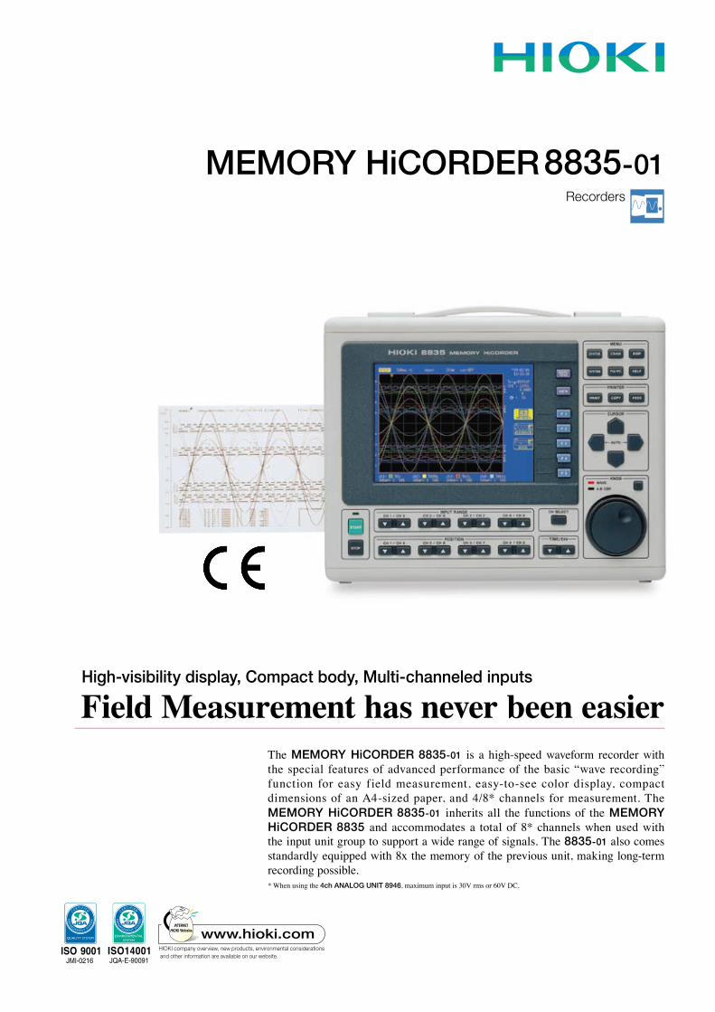
With a conventional pen recorder, even if all test data is written on the
paper, usually only a small portion of the data is needed. However, to
look for just a small important part requires very extensive search of the
recording paper.
The MEMORY HiCORDER 8835-01 stores
and manages all waveform measurement
data electronically. Furthermore, use of a LAN
card and the LAN COMMUNICATOR 9333
enables high-speed data file transfer to PCs
on a network.
A LAN-Connectable Recorder! Digitally Process Test Data
Example of using measurement data in Excel
- Features -● Converts to text file used with a Wave viewer (supplied
accessories, PC application software)
To open measurement data in PC applications such as Excel, the data must be converted to text data in the CSV format. The PC application software which comes standard in the package enables easy operation.
● Connects to PCs and printers on a LAN networkIts use with PCs can be selected according to the usage. It allows remote operation and data transfer via LAN connection, GP-IB connection, or RS-232C connection.
● Function upgrade system to meet varied needs The basic model provides several standard functions for users who don’t require functional complexity. Users requiring a wider range of measurement functions can add functions through the use of a function upgrade disk.
● On-screen help To help the user get started or clarify operating steps, the 8835-01 can display tips on-screen for many basic operations, including key-button operations.
● CE Mark compliant Complies with the EC directive determining safety standards in Europe (within the EU).
● Conversion According to the Measurement, Plug-in Input Function for a Maximum of 8 Channels*1
The 8835-01 employs a plug-in unit system that can change the measurement channels according to the measurement use. Directly inputting physical signals through inserted conversion amplifiers is also possible. A maximum of 8 channels*1 can be used for measurement by mounting a 4-channel analog unit on the recorder.
● High-visibility waveforms displayed on a 6.4-inch color TFT liquid crystal display
The color display makes it easier to identify waveforms and install the device. It enhances visibility and facilitates operations.
● Compact and thin, occupying a space equivalent to 60% of an A4-size sheet of paper
Occupying desktop space equivalent to 60% of an A4-size sheet of paper, the MEMORY HiCORDER 8835-01 is functionally designed so as to permit operation on a flat bed.
● Highly Improved Basic Performance with 1MS/s, 12bit-A/D, 4MW
The 8835 - 01 employs a sampl ing rate of 1MS/s (1μs cycle) and 12-bit voltage-axis resolut ion for the A /D conver ter unit, which digit izes measurement signals, enabling accurate detection of signal waveforms. With the 8835-01, the standard memory capacity is 4MW.
*1 When using the 4ch ANALOG UNIT 8946, maximum input is 30V rms or 60V DC
3
High-Speed Response for Capturing Transient Events
- Function Details -
■ Memory segmentation function (an optional FUNCTION UP DISK 9540-01 is needed)
When using the memory recorder function, the data memory can be divided into a maximum of 255 blocks. Data can be written sequentially to the memory blocks, and the waveform in a reference block and any other block can be superimposed and compared.
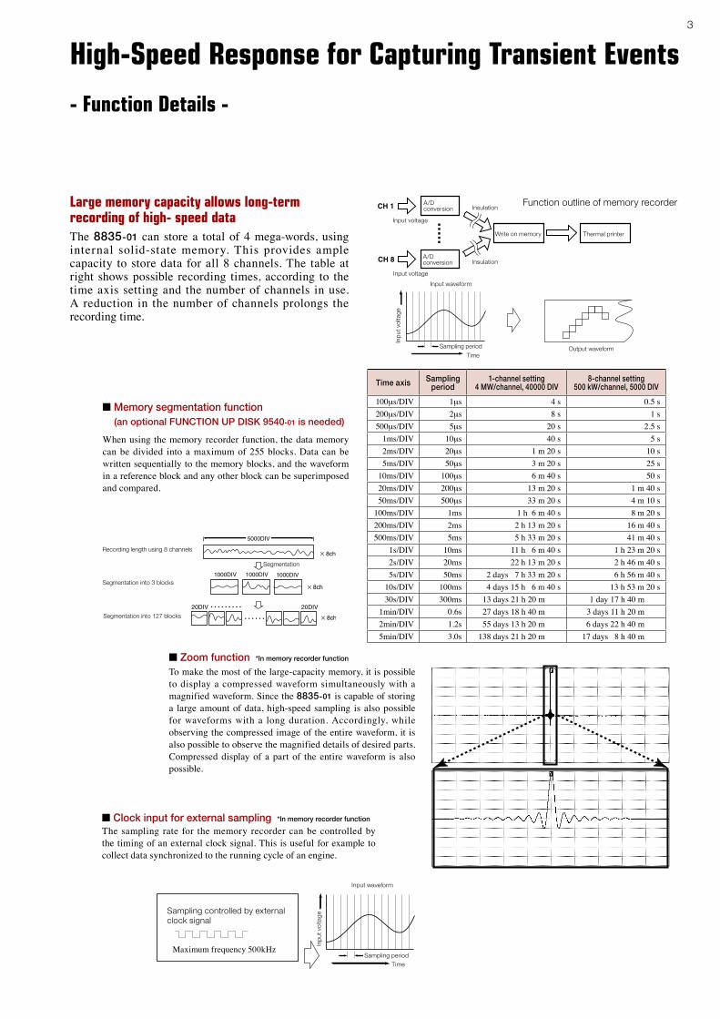
■ Zoom function *In memory recorder function
To make the most of the large-capacity memory, it is possible to display a compressed waveform simultaneously with a magnified waveform. Since the 8835-01 is capable of storing a large amount of data, high-speed sampling is also possible for waveforms with a long duration. Accordingly, while observing the compressed image of the entire waveform, it is also possible to observe the magnified details of desired parts. Compressed display of a part of the entire waveform is also possible.
■ Clock input for external sampling *In memory recorder function
The sampling rate for the memory recorder can be controlled by the timing of an external clock signal. This is useful for example to collect data synchronized to the running cycle of an engine.
Recording length using 8 channels
Segmentation into 3 blocks
Segmentation into 127 blocks
Segmentation
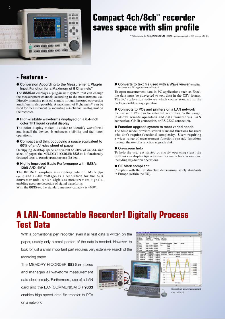
The 8835-01 can store a total of 4 mega-words, using internal solid-state memory. This provides ample capacity to store data for all 8 channels. The table at right shows possible recording times, according to the time axis setting and the number of channels in use. A reduction in the number of channels prolongs the recording time.
Large memory capacity allows long-term recording of high- speed data
Output waveformTime
Sampling period
Input voltage
Input voltage
Input waveform
Inp
ut v
olta
ge
A/Dconversion
A/Dconversion
Insulation
Insulation
Write on memory Thermal printer
Function outline of memory recorder
TimeSampling period
Input waveform
Inp
ut v
olta
ge
Sampling controlled by external clock signal
Maximum frequency 500kHz
Time axis Sampling period
1-channel setting 4 MW/channel, 40000 DIV
8-channel setting 500 kW/channel, 5000 DIV
100μs/DIV 1μs 4 s 0.5 s200μs/DIV 2μs 8 s 1 s500μs/DIV 5μs 20 s 2.5 s
1ms/DIV 10μs 40 s 5 s2ms/DIV 20μs 1 m 20 s 10 s5ms/DIV 50μs 3 m 20 s 25 s
10ms/DIV 100μs 6 m 40 s 50 s20ms/DIV 200μs 13 m 20 s 1 m 40 s50ms/DIV 500μs 33 m 20 s 4 m 10 s
100ms/DIV 1ms 1 h 6 m 40 s 8 m 20 s200ms/DIV 2ms 2 h 13 m 20 s 16 m 40 s500ms/DIV 5ms 5 h 33 m 20 s 41 m 40 s
1s/DIV 10ms 11 h 6 m 40 s 1 h 23 m 20 s2s/DIV 20ms 22 h 13 m 20 s 2 h 46 m 40 s5s/DIV 50ms 2 days 7 h 33 m 20 s 6 h 56 m 40 s
10s/DIV 100ms 4 days 15 h 6 m 40 s 13 h 53 m 20 s30s/DIV 300ms 13 days 21 h 20 m 1 day 17 h 40 m
1min/DIV 0.6s 27 days 18 h 40 m 3 days 11 h 20 m2min/DIV 1.2s 55 days 13 h 20 m 6 days 22 h 40 m5min/DIV 3.0s 138 days 21 h 20 m 17 days 8 h 40 m
4
High-speed response and Effective value recorder functions are useful in following signal variations
- Function Details -
Recording Time of the Recorder
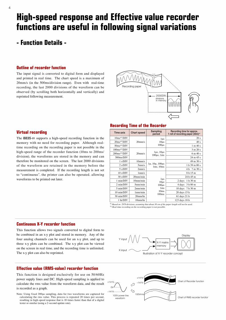
Outline of recorder functionThe input signal is converted to digital form and displayed and printed in real time. The chart speed is a maximum of 20mm/s (in the 500ms/division range). Even with real-time recording, the last 2000 divisions of the waveform can be observed (by scrolling both horizontally and vertically) and reprinted following measurement.
Virtual recording The 8835-01 supports a high-speed recording function in the memory with no need for recording paper. Although real-time recording on the recording paper is not possible in the high-speed range of the recorder function (10ms to 200ms/ division), the waveforms are stored in the memory and can therefore be monitored on the screen. The last 2000 divisions of the waveform are retained in the memory before the measurement is completed. If the recording length is not set to “continuous”, the printer can also be operated, allowing waveforms to be printed out later.
Effective value (RMS-value) recorder functionThis function is designed exclusively for use on 50/60Hz power supply lines and DC. High-speed sampling is applied to calculate the rms value from the waveform data, and the result is recorded as a graph.Note: Using fixed 200μs sampling, data for two waveforms are captured for
calculating the rms value. This process is repeated 20 times per second, resulting in high-speed response that is 10 times faster than that of a digital tester or similar (using a 2-second update rate).
This function allows two signals converted to digital form to be combined in an x-y plot and stored in memory. Any of the four analog channels can be used for an x-y plot, and up to three x-y plots can be combined. The x-y plot can be viewed on the screen in real time, and the recording time is unlimited. The x-y plot can also be reprinted.
Continuous X-Y recorder function
Time axis Chart speed Sampling period
Recording time for approx. 1 roll of recording paper (30m)*1
10ms*2/DIV20mm/s
1μs10μs
100μs
20 s20ms*2/DIV 40 s50ms*2/DIV 1 m 40 s
100ms*2/DIV20mm/s 1μs, 10μs
100μs, 1ms
3 m 20 s200ms*2/DIV 6 m 40 s
500ms/DIV 24 m 45 s1 s/DIV 10mm/s
1μ, 10μ, 100μs1ms, 10ms
49 m 30 s2 s/DIV 5mm/s 1 h 39 m 00 s5 s/DIV 2mm/s 4 h 7 m 30 s
10 s/DIV 1mm/s
1μs10μs
100μs1ms
10ms100ms
8 h 15 m30 s/DIV 20mm/min 24 h 45 m
1 min/DIV 10mm/min 2 days 1 h 30 m2 min/DIV 5mm/min 4 days 3 h 00 m5 min/DIV 2mm/min 10 days 7 h 30 m
10 min/DIV 1mm/min 20 days 15 h30 min/DIV 20mm/hr 61 days 21 h
1 hr/DIV 10mm/hr 123 days 18 h*1 Based on 2970 divisions, assuming that about 30 cm of the paper length will not be used.*2 Real-time recording on the recording paper is not possible.
5
Easily interfaced with a PC or a waveform comparator
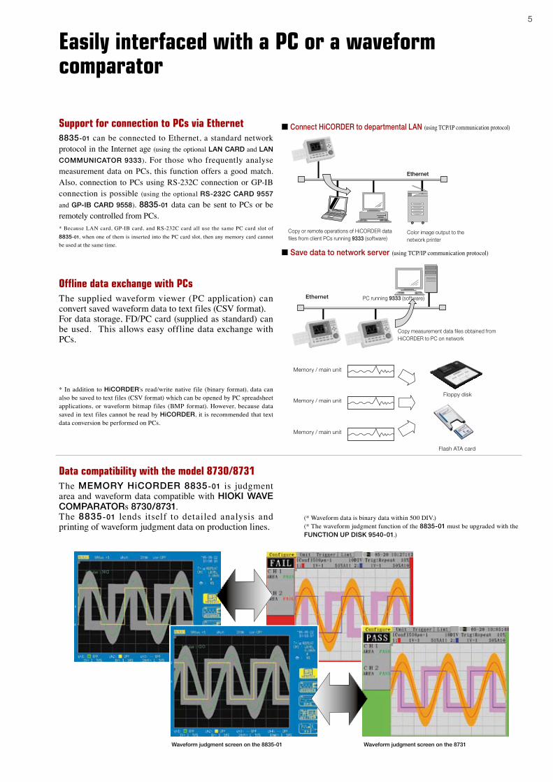
Support for connection to PCs via Ethernet8835-01 can be connected to Ethernet, a standard network protocol in the Internet age (using the optional LAN CARD and LAN
COMMUNICATOR 9333). For those who frequently analyse measurement data on PCs, this function offers a good match. Also, connection to PCs using RS-232C connection or GP-IB connection is possible (using the optional RS-232C CARD 9557 and GP-IB CARD 9558). 8835-01 data can be sent to PCs or be remotely controlled from PCs. * Because LAN card, GP-IB card, and RS-232C card all use the same PC card slot of 8835-01, when one of them is inserted into the PC card slot, then any memory card cannot be used at the same time.
■ Connect HiCORDER to departmental LAN (using TCP/IP communication protocol)
Ethernet
Color image output to the network printer
Copy or remote operations of HiCORDER data files from client PCs running 9333 (software)
■ Save data to network server (using TCP/IP communication protocol)
Ethernet
Copy measurement data files obtained from HiCORDER to PC on network
PC running 9333 (software)
Offline data exchange with PCsThe supplied waveform viewer (PC application) can convert saved waveform data to text files (CSV format).For data storage, FD/PC card (supplied as standard) can be used. This allows easy offline data exchange with PCs.
Floppy disk
Flash ATA card
Memory / main unit
Memory / main unit
Memory / main unit
* In addition to HiCORDER's read/write native file (binary format), data can also be saved to text files (CSV format) which can be opened by PC spreadsheet applications, or waveform bitmap files (BMP format). However, because data saved in text files cannot be read by HiCORDER, it is recommended that text data conversion be performed on PCs.
Waveform judgment screen on the 8731Waveform judgment screen on the 8835-01
Data compatibility with the model 8730/8731The MEMORY HiCORDER 8835-01 is judgment area and waveform data compatible with HIOKI WAVE COMPARATORs 8730/8731. The 8835-01 lends itself to detailed analysis and printing of waveform judgment data on production lines.
(* Waveform data is binary data within 500 DIV.) (* The waveform judgment function of the 8835-01 must be upgraded with the FUNCTION UP DISK 9540-01.)
6
The results of waveform decisions, parameter decisions, and triggers are output as open collector signals. The 8835-01 is also provided with signal inputs for remote control of the start, stop, and print buttons.
The 8835-01 has a dual AC/DC power-supply specification, and an external battery can be used by means of the DC POWER ADAPTER 9439, in addition to normal AC power supply. This allows vehicle-mounted applications, where an AC power supply is not available. If both supplies are connected, the AC power supply takes precedence, but if the AC power fails, the unit automatically switches to DC operation.
Signal outputs, control inputs, DC input
* When using the F/V UNIT 8940 with 12 V DC power, the printer can only be used for up to 2 channels.
Variable (span adjustment), vernier (fine adjustment)When sensors a re used to measure and record noise, temperature, acceleration or other physical quantities, precise calibration is important. This is facilitated by the vernier function that allows fine adjustment of amplitude. The variable function lets the user numerically specify the measurement span, such as 1 - 5V or 4 - 20mA. This is useful for matching the range of instrumentation to the full span of the recording paper. A scaling function for converting measurement results is also available.
External trigger input
Trigger signal output
External control connector
DC input (The DC POWER ADAPTER 9439 must be used)
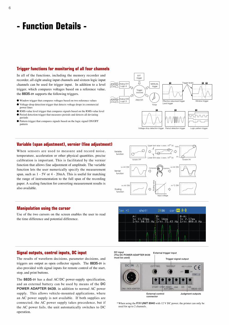
Manipulation using the cursorUse of the two cursors on the screen enables the user to read the time difference and potential difference.
- Function Details -
In all of the functions, including the memory recorder and recorder, all eight analog input channels and sixteen logic input channels can be used for trigger input. In addition to a level trigger, which compares voltages based on a reference value, the 8835-01 supports the following triggers.
● Window trigger that compares voltages based on two reference values ● Voltage-drop detection trigger that detects voltage drops in commercial
power lines ● RMS-value level trigger that compares signals based on the RMS-value level ● Period detection trigger that measures periods and detects all deviating
periods ● Pattern trigger that compares signals based on the logic signal ON/OFF
pattern
Trigger functions for monitoring of all four channels
Judgment outputs

7
Upgrading provides sophisticated functions
If an abnormal event is detected by triggers during the real-time recording of signals using the recorder function, it is stored in memory by the high-speed sampling memory recorder. The recorder function works independently and is therefore continuous. These functions are useful when the user wants to record normal waveforms as well as abnormal waveforms.
Recorder and memory functions
The single-channel FFT function is used in spectrum analysis. The two-channel FFT function analyzes transfer functions. The octave analysis function is used in acoustic analysis. The signal source for FFT analysis is a section obtained from the waveforms captured in the memory recorder (the required number of pieces of data for FFT analysis are 1000, 2000, 5000
and 10000).
FFT analysis functions
Additional functions provided by the FUNCTION UP DISK 9540-01 (with the 8835, use the FUNCTION UP DISK 9540)
Simultaneous computation on eight channelsIt is possible to simultaneously compute four different types of waveforms, each of which has been captured on one of the eight channels in memory recorder mode. The results of four basic arithmetic computations, differentiation, or integral are displayed in a waveform. (The waveform computation requires a FUNCTION UP DISK. 9540-01 With the 8835, the waveform computation requires a FUNCTION UP DISK 9540.) For parameter calculations that calculate numerical values such as the maximum and minimum values, up to eight waveforms can be operated simultaneously on four channels.(The parameter operations are a standard function.)
Waveform judgment screen on the 8835-01
Waveform judgment screen on the
8731
The 8835-01 can monitor a measured waveform for a preset judgment area. Unlike a voltage level only comparison such as a trigger setting, this function makes it possible to easily prepare a standard judgment area making it an excellent system for comparisons both in level direction and in time axis direction.
Patented: Registration number 2028013
The 8835-01 is waveform data and area data compatible with the WAVE COMPARATOR 8730 and 8731. (* Waveform data is binary data within 500 DIV. The 8730 and 8731 comparators do not provide an FFT analysis function.)
Waveform judgment functions *In memory recorder functions and FFT analysis functions
8
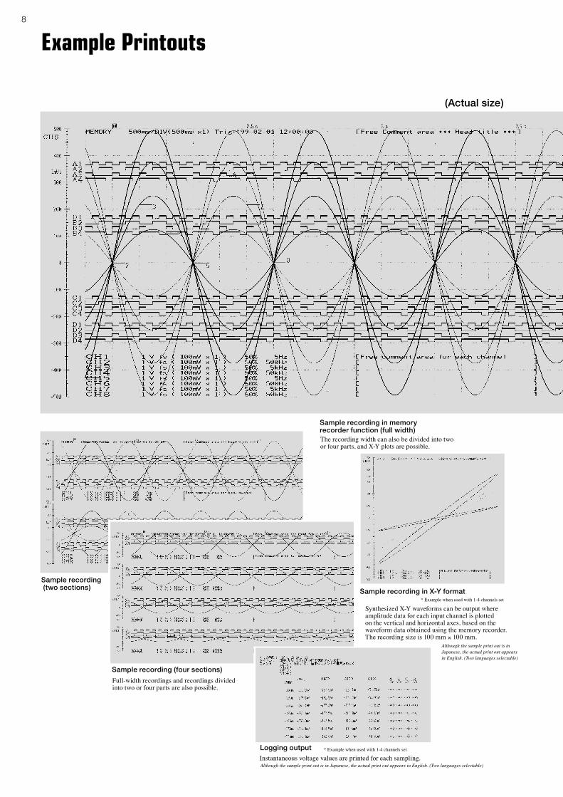
Example Printouts
The recording width can also be divided into two or four parts, and X-Y plots are possible.
Sample recording in memory recorder function (full width)
Full-width recordings and recordings divided into two or four parts are also possible.
Sample recording (four sections)
Sample recording (two sections)
(Actual size)
Synthesized X-Y waveforms can be output where amplitude data for each input channel is plotted on the vertical and horizontal axes, based on the waveform data obtained using the memory recorder. The recording size is 100 mm × 100 mm.
Sample recording in X-Y format* Example when used with 1-4 channels set
Instantaneous voltage values are printed for each sampling. Logging output * Example when used with 1-4 channels set
Although the sample print out is inJapanese, the actual print out appearsin English. (Two languages selectable)
Although the sample print out is in Japanese, the actual print out appears in English. (Two languages selectable)

9
Basic specifications 8835-01 (use 2ch input type modules) 8835-01 (use 4ch ANALOG UNIT 8946)
Input type/number of channels
Plug-in input modulesMax. 4 analog ch’s + 16 logic ch’s(Isolated analog channels, isolated input and frame, logic has common GND)
Plug-in input modulesMax. 8 analog ch’s + 16 logic ch’s(Isolated analog channels, isolated input and frame, logic has common GND)
Measurement functions
MEM (high-speed recording)REC (real-time recording)RMS (50/60Hz, or DC only)REC & MEM (Additional functions provided by the optional FUNCTION UP DISK 9540-01)FFT (Additional functions provided by the optional FUNCTION UP DISK 9540-01)
Maximum sampling rate
1 MS/second (1μs, all channels simultaneously)External sampling (500kS/second, 2μs)
Memory capacity4 Mwords total(12 analog bits + 4 logic bits) × 4 Mwords/channel (1 channel used) to (12 analog bits + 4 logic bits) × 500 kwords/channel (8 channels used)
Data storage mediaPC Card Type III slot × 1: up to 1GB (Flash ATA)3.5" Floppy disk drive × 1: 1.44MB, 1.2MB, 720KB, MS-DOS formatFile format: Binary, text, BMP
Backup functions(at 25°C)
Clock and setting conditions: battery life of at least 10 years Waveform data: battery life of at least 1 hour after system power is turned OFF (at 2 minutes after power-on)
External control connectors
Mini-jack 3.5 mm in dia.: Trigger input/output Terminal board: External start, stop, print input/sampling input, decision output
Interfaces (option)GP-IB, RS-232C, LANNote: Use one of the following: RS-232C CARD 9557, GP-IB CARD 9558, LAN CARD (HIOKI-tested)
Environmental conditions(no condensation)
Operation: +5°C (41°F) to +40°C (104°F), 35% to 80% rhStorage: -10°C (14°F) to +50°C (122°F), 20% to 90% rh
Compliance standard
Safety: EN61010EMC: EN61326, EN61000-3-2, EN61000-3-3
Power requirements
100 to 120V AC or 200 to 240V AC (50/60 Hz)10 to 28V DC (use the DC POWER ADAPTER 9439 : option)
Power consumption (when using two units of 8936)
120VA, max. for 100V AC (approx. 60VA with the printer off) 70VA, max. for 12V DC (approx. 30VA with the printer off)
Power consumption (when using two units of 8940)
170VA, max. for 100V AC (approx. 110VA with the printer off) 80VA, max. for 12V DC (approx. 50VA with the printer off) Note: When using the F/V UNIT 8940 with 12V DC power, the printer can only be used for up to 2 channels.
Dimensions and mass
285mm (11.22in) W × 220mm (8.66in) H × 132mm (5.20in) D, 4.5kg (158.73oz.) (main unit only)
Supplied accessories
Instruction Manual × 1, Power cord × 1, Printer paper ×1, Protective cover ×1, Roll paper attachment ×2, PC card protector ×1, Application Disk (Wave Viewer Wv, Communication Commands table) ×1
Print/display sectionDisplay 6.4 inch TFT color LCD, with English/Japanese selector (640 × 480 dots)
Recording paper 110 mm (4.33 in) × 30 m (98.4 ft), thermal paper rollRecording width 10 divisions for full scale, 1 DIV = 10 mm (0.39 in) (80 dots)
Paper feed density 10 rows/mm (250 rows/in) * 20 rows/mm (500 rows/in with the memory recorder's smooth print function
Recording speed Max. 25 mm/s (0.98 in/s)
Trigger functions
Trigger sourcesCH1 to CH8 (analog), CHA to CHD (logic), external, timer, manual (either ON or OFF for each source), logical AND/OR of sources
Trigger types(analog)
Level: Digital setting of voltage. Triggered when set value is exceeded in UP or DOWN direction.
Window: When entering or exiting a level range defined by upper or lower limit
Voltage drop: Only for AC power lines. Triggered when the peak voltage falls below setting value
RMS level: Only for DC and AC power lines. Triggered when rms value crosses set value in UP or DOWN direction
Period: When rising or falling edge of set voltage does not fall within cycle range
Level setting resolution Equivalent to 0.25% when full scale is set to 10 divisions
Trigger types(logic)
Pattern trigger: 1, 0, or × (disregard), logical product (AND) or logical sum (OR) set for 4 channels
Trigger filter(analog/logic)
OFF, setting range 0.1 to 10.0 DIV in 9 stages (MEM, REC & MEM function), ON/OFF (REC function)
Other functionsPre-trigger function to capture pre- and post-trigger waveform, trigger output (active Low with f 3.5mm mini-jack and open collector 5 voltage output), Start & stop trigger in REC function
Memory functions
Time axis100μs to 5min/DIV, 20 ranges or external sampling, time axis resolution 100 points/DIV, time axis zoom: ×2 to ×10 in 3 stages, compression: 1/2 to 1/2,000 in 10 stages
Sampling rate 1/100 of time axis ranges (minimum sampling period 1μs)External sampling Max. 500kS/s (minimum sampling period 2μs)
Recording length Settable in 1 DIV steps, 20 to 40,000 DIV*1
*1 Depending on the number of channels in use.
Pre-triggerCan record data from before the trigger point, 0 to 100% or -95% of recording length; 15 settings
Other functions
waveform processing*2, waveform parameter processing, waveform averaging*2, memory segmentation (up to 255 segments)*2, logging (numerical printout), X-Y waveform plot, voltage axis zoom ×2 to ×10, 3 settings, compression 1/2, zoom, variable display, graph superimposition, waveform judgment function*2
*2 Additional functions provided by the optional FUNCTION UP DISK 9540-01
Recorder functions (time axis waveform and X-Y format)
Time axis
10ms to 1 hour/DIV with 17 ranges, time axis resolution 100 points/DIV, time axis compression: 1/2 to 1/50 in 5 stagesAt 10ms to 200ms/DIV, printing in real time is not possible, but waveform data are stored in
memory and can be monitored on screen. Data are stored for 2,000 divisions before the end of measurement. At recording length settings other than "Continuous", the printer can be used simultaneously, for follow-up printing of waveforms.
Sampling rate 1μs to 100ms; 6 settings (selectable from 1/100 or less of time axis)
Recording length
Settable in 1 DIV steps, 20 to 2,000 DIV*3, or "Continuous"*4
At X-Y format: only continuous for X-Y plotting*3 Measure all channels.*4 When time 10 ms − 200 ms/DIV and printer is ON, continuous is not available.
X-Y sampling period 100μs; fixed (dot), 100μs to 25ms (line)X-Y axis resolution 40dots/DIV (display), 80dots (horizontal) × 80 dots (vertical)/DIV (printer)
Waveform memoryStore data for most recent 2,000 DIV in memory. Backward scrolling and re-printing available.
Other functionslogging (numerical printout), additional recording (recording is resumed without overwriting previous data), voltage axis magnification ×2 to ×10; 3 settings, compression 1/2; 1 setting, variable display.
RMS Recorder Function (for 50/60 Hz and DC)
Time axis 5s to 1 hr/DIV; 9 settings, time axis compression 1/2 to 50; 5 settingsSampling rate 200μs fixed (20 rms datas/s)
RMS calculation accuracy ±3% f.s.
Recording length Settable in 1 DIV steps, 20 to 2,000 DIV*5, or "Continuous"*5 Measure all channels.
Waveform memoryStore data for most recent 2,000 DIV in memory. Backward scrolling and re-printing available.
Other functionslogging (numerical printout), additional recording (recording is resumed without overwriting previous data), voltage axis magnification ×2 to ×10; 3 settings, compression 1/2; 1 setting, variable display.
Auxiliary Functions
General
Printing of settings including input range, trigger time, etc, cursor measurement, scaling, free comment input, screen hard copy, registration of setting conditions (eight conditions), start condition retention, auto setup, auto saving, remote control, auto ranging, view function, online help, key lock, list printing, etc.
ScalingScaling: Translation of amplitude gradation onlyVariable: Arbitrary setting of the upper and lower limit of the waveform display range
Vernier function Allows precision adjustment of input voltage.
Waveform parameter calculation (in MEM function)
Average value, effective (rms) value, peak to peak value, maximum value, time to maximum value, minimum value, time to minimum value, period, frequency, rise time, fall time, area value, X-Y area value, and standard deviation.
■ PC Software Specifications
Wave Viewer (Wv) Software (Application disk CD-R, bundled accessory)
Functions
• Simple display of waveform file • Text conversion: convert binary data file to text format, with selectable space or tab separators in addition to CSV, and speci-fiable section, thinning available
• Display format settings: scroll functions, enlarge/reduce dis-play, display channel settings
• Others: voltage value trace function, jump to cursor/trigger position function
Compatible PC operating systems Windows 95/98/Me, Windows NT 4.0 (SP3 or later), 2000, XP
Analog input unit mount
External control terminal
DC power inletConnect the optional DC POWER ADAPTER 8439
AC power inlet
PC card slot for type-III cardsA PC card-type GP-IB or RS-232C interface is used for this slot as well.
Floppy-disk drive
Waveform monitor (color TFT LCD)
Thermal printer: 110 mm in width, 8 dots/mm
Logic probes input terminals

10
STRAIN UNIT 8939 (Accuracy at 23 ±5°C/73 ±9°F, 35 to 80 % rh after 1 hour of warm-up time and auto-balance; accuracy guaranteed for 1 year)
Measurement functions
Number of channels: 2, for distortion measurement (electronic auto-balancing, balance adjustment range within ±10000με)
Input connectorsVia conversion cable, TAJIMI PRC03-12A10-7M10.5, Max. rated voltage to earth: 30Vrms or 60V DC (with input isolated from the unit, the maximum voltage that can be applied between input channel and chassis and between input channels without damage)
Suitable transducer
Strain gauge converter, bridge impedance: 120Ω to 1kΩ, bridge voltage 2 ±0.05V
Measurement range
50με to 2000με/DIV, 6 ranges, full scale: 10DIV, low-pass filter: 10Hz/30Hz/300Hz/3kHz
Measurement resolution 1/160 of measurement range (using 12-bit A/D conversion; installed in 8835-01)
Highest sampling rate 1MS/s (2-channel simultaneous sampling)
Accuracy After auto-balancing DC amplitude: ±(0.5% of full scale +2με), zero position: ±0.5% of full scaleFrequency characteristics DC to 20 kHz +1/−3dBMax. allowable input 10V DC + AC peak (the maximum voltage that can be applied across input pins without damage)
FUNCTION UP DISK 9540-01 Additional functions to the MEMORY HiCORDER 8835-01
REC & MEM functions Additional functions provided by the FUNCTION UP DISK 9540-01
Time axis (REC)
500ms to 1hour/DIV; 17 settings, 1 DIV = 100 samples, time axis compression 1/2 to 1/50, 5 settingsNote: Sampling period 1/100 of time axis range at MEM function
Time axis (MEM)
100μs to 5 minutes/DIV; 20 settings, 1 DIV = 100 samples, time axis zoom ×2 to ×10; 3 settings, compression 1/2 to 1/2000, 10 settingsNote: Sampling period 1/100 of time axis range (min. 1μs)
Recording lengthREC: Settable in 1-division steps, 20 to 1,000 DIV, or continuousMEM: Settable in 1-division steps, 20 to 2,000 DIV
Trigger sourceREC: timer trigger, or OFFMEM: CH1 to CH8 (analog), logic A to D, or external trigger
Other functions
Only real-time waveform is output when printer output is started, reprinting of stored REC waveform data (last 1000 DIV), Additional recording function (recording is resumed without overwriting previous data), variable display
FFT functions Additional functions provided by the FUNCTION UP DISK 9540-01
Analysis mode
Storage waveform, Linear spectrum, RMS spectrum, Power spectrum, Cross-power spectrum, Auto-correlation function, Histogram, Transfer function, Cross-correlation function, Unit-impulse response, Coherence function, Octave analysis
Analysis channels 1 or 2 selected channels out of all analog channelsFrequency range 133mHz to 400kHz, External, (resolution 1/400, 1/800, 1/2000, 1/4000)
Number of sampling points
1000, 2000, 5000, 10000 points
Analysis dataSelected from: Newly loaded data / MEM function waveform data / MEM waveform of REC & MEM function
Windows Rectangular, Hanning, Exponential
Averaging function
Time axis / frequency axis simple averaging, exponential averaging, peak hold
Additional features Additional functions provided by the FUNCTION UP DISK 9540-01
Waveform processing calculations (MEM function)
(Maximum possible calculation up to 1000 DIV; accuracy is within the tolerance of the input module.)Four arithmetic operations, absolute value, exponentiation, common logarithm, square root, moving average, differentiation once and twice, integration once and twice, parallel displacement along the time axis. 8 arbitrary operational equation.
Waveform judgment function (MEM function)(FFT function)
Type: Area judgment using reference waveform for time axis waveform, X-Y plot, or FFT display. Parameter judgment for waveform parameter processing. Judgment output: pass/fail output, open-collector 5V voltage output
Others Waveform averaging; memory segmentation (up to 255 segments)
■ Options (sold separately)
■ Input unit specifications (sold separately)
ANALOG UNIT 8936 (Accuracy at 23 ±5°C/73 ±9°F, 35 to 80 % rh after 30 minutes of warm-up time and zero-adjust; accuracy guaranteed for 1 year)
Measurement functions Number of channels: 2, for voltage measurement
Input connectorsIsolated BNC connector (input impedance 1MΩ, input capacitance 30pF), Max. rated voltage to earth: 370V AC, DC (with input isolated from the unit, the maximum voltage that can be applied between input channel and chassis and between input channels without damage)
Measurement range
10mV to 50V/DIV, 12 ranges, full scale: 10DIV, AC voltage for possible measurement/display using the memory function: 280V rms, low-pass filter: 5Hz/500Hz/5kHz/100kHz
Measurement resolution 1/160 of measurement range (using 12-bit A/D conversion; installed in the 8835-01)
Highest sampling rate 1MS/s (simultaneous sampling in 2 channels)
Accuracy DC amplitude: ±0.4% of full scale, zero position: ±0.1% of full scale (after zero adjustment)
Frequency characteristics DC to 400kHz ±3dB, with AC coupling: 7Hz to 400kHz ±3dBInput coupling DC, GND, ACMax. allowable input 400V DC (the maximum voltage that can be applied across input pins without damage)
Dimensions and mass: approx. 170 (6.69in) W × 20 (0.79in) H × 148.5 (5.85in) D mm, approx. 290 g (10.2 oz) Accessories: None
FFT ANALOG UNIT 8938 (Accuracy at 23 ±5°C/73 ±9°F, 35 to 80 % rh after 30 minutes of warm-up time and zero-adjust; accuracy guaranteed for 1 year)
Measurement functions Number of channels: 2, for voltage measurement
Anti-aliasing filterIntegrated filter for suppressing aliasing distortion caused by FFT processing (automatic cutoff frequency setting/OFF)
Other functions Other specifications same as the ANALOG UNIT 8936
VOLTAGE/TEMP UNIT 8937 (Accuracy at 23 ±5°C/73 ±9°F, 35 to 80 % rh after 1 hour of warm-up time and zero-adjust; accuracy guaranteed for 1 year)
Measurement functions Number of channels: 2, for voltage measurement/temperature measurement with thermocouple
Input connectors
Voltage input: metallic BNC connector (input impedance 1MΩ, input capacitance 50pF), thermocouple input: terminal connector (input impedance min. 5.1MΩ), Max. rated voltage to earth: 30Vrms or 60V DC (with input isolated from the unit, the maximum voltage that can be applied between input channel and chassis and between input channels without damage)
Voltage measurement range
1mV to 5V/DIV, 12 ranges, full scale: 10DIV, low-pass filter: 5Hz/ 500Hz/ 5kHz/ 100kHz, Measurement resolution: 1/160 of measurement range (using 12-bit A/D conversion; installed in the 8835-01)
Temperature measurement range
20°C to 200°C/DIV, 4 ranges, full scale: 10DIV, low-pass filter: 5Hz/500Hz, Measurement resolution:1/160 of measurement range (using 12-bit A/D conversion; installed in the 8835-01)
Thermocouple range
K: -200 to 1350°C, E: -200 to 800°C, J: -200 to 1100°C, T: -200 to 400°C,N: -200 to 1300°C, R: 0 to 1700°C, S: 0 to 1700°C, B: 300 to 1800°C, Reference junction compensation: internal/ external (switchable)
Highest sampling rate Voltage input: 1MS/s, Temperature measurement: 4kS/s (simultaneous sampling in 2 channels)
Accuracy
Voltage input: DC amplitude ±0.4% of full scale, zero position ±0.15% of full scale, Temperature measurement (K, E, J, T, N): ±0.1% of full scale ±1°C, ±0.1% of full scale ±2°C (-200 to 0°C), (R, S): ±0.1% of full scale ±3°C, (B): ±0.1% of full scale ±4°C (400 to 1800°C) , Reference junction compensation accuracy: ±0.1% of full scale ±1.5 °C (internal reference junction compensation)
Frequency characteristics
Voltage input: DC to 400 kHz +1/−3dBTemperature measurement: DC to 1kHz +1/−3dB
Input coupling DC, GND, ACMax. allowable input 30Vrms or 60V DC (the maximum voltage that can be applied across input pins without damage)
Dimensions and mass: approx. 170 (6.69in) W × 20 (0.79in) H × 148.5 (5.85in) D mm, approx. 300 g (10.6 oz) Accessories: None
Dimensions and mass: approx. 170 (6.69in) W × 20 (0.79in) H × 148.5 (5.85in) D mm, approx. 250 g (8.8 oz) Accessories: Conversion cable × 2
F/V UNIT 8940 (Accuracy at 23 ±5°C/73 ±9°F, 35 to 80 % rh after 30 minutes of warm-up time and zero-adjust; accuracy guaranteed for 1 year)
Measurement functions
Number of channels: 2, for voltage input based frequency measurement, integration, pulse duty ratio, current (with optional clamp-on sensor), and voltage measurement
Input connectors
Metallic BNC connector (input impedance 1MΩ, input capacitance 60pF), sensor connector (dedicated connector for clamp-on sensor via conversion cable, common ground with recorder), Max. rated voltage to earth: 30Vrms or 60V DC (with input isolated from the unit, the maximum voltage that can be applied between input channel and chassis and between input channels without damage)
Compatible current sensors 9270, 9271, 9272, 9277, 9278, 9279, 3273, 3273-50
Measurement range
Frequency: DC to 100kHz, with 0.1Hz to 10kHz/DIV, 11 ranges, 10 (r/min) to 1k (r/min)/DIV, 5ranges, P50Hz (40 to 60Hz), P60Hz (50 to 70Hz) * Power line frequency measurement requires the DIFFERENTIAL PROBE 9322 or PT 9303, Accuracy: ±0.2% of full scale (except 10kHz/DIV range), ±0.7% of full scale (10kHz/DIV range), ±0.032Hz (P50Hz, P60Hz range)
Integration: DC to 90kHz, with 10counts to 1Mcounts/DIV, 11 rangesPulse duty ratio: 10Hz to 100kHz, with 100% of full scale, 1 range,
Accuracy: ±1% of full scale (10Hz to 10kHz)Threshold: −10 to +10V (settable in 0.2V steps)Full scale: 10DIV, Max. allowable input: 30Vrms or 60V DC (the
maximum voltage that can be applied across input pins without damage)
Measurement range
Voltage: 1mV to 5V/DIV, 12 rangesCurrent: 10mA to 200A/DIV, 10 ranges, using current sensor (powered
from the 8940, max. 4 sensors total)DC amplitude accuracy: ±0.4% of full scale, zero position ±0.15%
of full scale (current measurement accuracy dependent on sensor accuracy/characteristics)
Frequency characteristics: DC to 400kHz ±3dBFull scale: 10DIV, Max. allowable input: 30Vrms or 60V DC (the
maximum voltage that can be applied across input pins without damage)
Measurement resolution 1/160 of measurement range (installed in 8835-01, excluding current range when using 9279)
Highest sampling rate 1MS/s (simultaneous sampling in 2 channels), (frequency/duty ratio measurement: 1.125μs cycle)
Other functionsVoltage input pull-up: ON (10kΩ)/OFF, input coupling: DC, GND, AC (voltage/current), DC (others), low-pass filter: 5Hz/500Hz/5kHz/100kHz
* The 8940 can be used with the 8835-01. but the 8835, main unit only, current probe cannot be used. The 8940 can be used with the 8835 standard models later than Ver. 2.10, 9540 install models later than Ver.5.10 can be used.
Dimensions and mass: approx. 170 (6.69in) W × 20 (0.79in) H × 148.5 (5.85in) D mm, approx. 300 g (10.6 oz) Accessories: None
CONVERSION CABLE 9318 (to connect 9270 to 9272, 9277 to 9279 and 8940)CONVERSION CABLE 9319 (to connect 3273, 3273-50 and 8940)
11
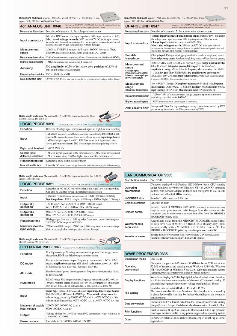
4ch ANALOG UNIT 8946 (Accuracy at 23 ±5°C/73 ±9°F, 35 to 80 % rh after 30 minutes of warm-up time and zero-adjust; accuracy guaranteed for 1 year)
Measurement functions Number of channels: 4, for voltage measurement
Input connectors
Metallic BNC connector (input impedance 1MΩ, input capacitance 15pF), Max. rated voltage to earth: 30Vrms or 60V DC (with input isolated from the unit, the maximum voltage that can be applied between input channel and chassis and between input channels without damage)
Measurement range
20mV to 5V/DIV, 8 ranges, full scale: 10DIV, low-pass filter, 5Hz/500Hz/5kHz/50kHz, input coupling: DC, GND
Measurement resolution 1/160 of measurement range (using 12-bit A/D conversion; installed in the 8835-01)
Highest sampling rate 1MS/s (simultaneous sampling in 4 channels)
AccuracyDC amplitude: ±0.5% of full scale, zero position: ±0.15% of full scale (after zero adjustment)
Frequency characteristics DC to 100kHz ±3dBMax. allowable input 30Vrms or 60V DC (the maximum voltage that can be applied across input pins without damage)
Dimensions and mass: approx. 170 (6.69in) W × 20 (0.79in) H × 148.5 (5.85in) D mm, approx. 310 g (10.9 oz) Accessories: None
CHARGE UNIT 8947 (Accuracy at 23 ±5°C/73 ±9°F, 35 to 80 % rh after 1 hour of warm-up time and zero-adjust; accuracy guaranteed for 1 year)
Measurement functions Number of channels: 2, for acceleration measurement
Input connectors
Voltage input/integrated preamplifier input: metallic BNC connector (for voltage input: input impedance 1MΩ, input capacitance 200pF or less)Charge input: miniature connector (#10-32 UNF)Max. rated voltage to earth: 30Vrms or 60V DC (with input isolated from the unit, the maximum voltage that can be applied between input channel and chassis and between input channels without damage)
Suitable transducer
Charge input: Charge-output type piezoelectric acceleration pick-up sensorInternal preamp input: Acceleration pick-up sensor with an internal preamp
Measurement rangeCharge input (miniature connector)Internal pre-amp input (BNC connector)
100m (m/s2)/DIV to 20k (m/s2)/DIV, 12 ranges × 6 types, charge input sensitivity: 0.1 to 10 pC/(m/s2), integrated pre-amplifier input: 0.1 to 10 mV/(m/s2), amplitude accuracy: ±2% of full scale, frequency characteristics: 1 to 50kHz, +1/−3dB, low-pass filter: 500Hz/5kHz, pre-amplifier drive power source: 2mA ±20%, +15V ±5%, maximum input charge: ±500pC (high-sensitivity setting, 6 ranges), ±50000pC (low-sensitivity setting, 6 ranges)
Measurement rangeVoltage input (BNC connector)
1mV to 5V/DIV, 12 ranges, DC amplitude accuracy: ±0.4% of full scale, frequency characteristics: DC to 400kHz, +1/−3 dB, low-pass filter: 5Hz/500Hz/5kHz/100kHz, input coupling: DC, GND, AC, Max. allowable input: 30Vrms or 60V DC
Measurement resolution 1/160 to 1/64 of measurement range (depending on measurement sensitivity; installed in the 8835-01)
Highest sampling rate 1MS/s (simultaneous sampling in 2 channels)
Anti-aliasing filter Integrated filter for suppressing aliasing distortion caused by FFT processing (automatic cutoff frequency setting/OFF)
Dimensions and mass: approx. 170 (6.69in) W × 20 (0.79in) H × 148.5 (5.85in) D mm, approx. 310 g (10.9 oz) Accessories: None
LOGIC PROBE 9320 (Accuracy at 23 ±5°C/73 ±9°F, 35 to 80% rh; accuracy guaranteed for 1 year)
Function Detection of voltage signal or relay contact signal for High/Low state recording
Input
4 channels (common ground between unit and channels), digital/contact input, switchable (contact input can detect open-collector signals), input impedance: 1MΩ (with digital input, 0 to +5V), 500kΩ or more (with digital input, +5 to +50V), pull-up resistance: 2kΩ (contact input: internally pulled up to +5V)
Digital input threshold 1.4V/2.5V/4.0V
Contact input detection resistance
1.5kΩ or higher (open) and 500Ω or lower (short), 3.5kΩ or higher (open) and 1.5kΩ or lower (short), 25kΩ or higher (open) and 8kΩ or lower (short)
Response speed Detectable pulse width 500ns or lowerMax. allowable input 0 to +50V DC (the maximum voltage that can be applied across input pins without damage)
Cable length and mass: Main unit cable 1.5 m (4.92 ft), input section cable 30 cm (0.98 ft), approx. 150 g (5.3 oz)
LOGIC PROBE 9321 (Accuracy at 23 ±5°C/73 ±9°F, 35 to 80% rh; accuracy guaranteed for 1 year)
FunctionDetection of AC or DC relay drive signal for High/Low state recordingCan also be used for power line interruption detection
Input4 channels (isolated between unit and channels), HIGH/LOW range switchingInput impedance: 100kΩ or higher (HIGH range), 30kΩ or higher (LOW range)
Output (H) detection
170 to 250V AC, ±DC (70 to 250V ) (HIGH range)60 to 150V AC, ±DC (20 to 150V) (LOW range)
Output (L) detection
0 to 30V AC, ±DC (0 to 43V) (HIGH range)0 to 10V AC, ±DC (0 to 15V) (LOW range)
Response time Rising edge 1ms max., falling edge 3ms max. (with HIGH range at 200V DC, LOW range at 100V DC)
Maximum allowable input voltage
250Vrms (HIGH range), 150Vrms (LOW range) (the maximum voltage that can be applied across input pins without damage)
Cable length and mass: Main unit cable 1.5 m (4.92 ft), input section cable 1 m (3.28 ft), approx. 320 g (11.3 oz)
DIFFERENTIAL PROBE 9322 (Accuracy at 23 ±5°C/73 ±9°F, 35 to 80% rh, after 30 minutes of warm-up time; accuracy guaranteed for 1 year)
FunctionFor high-voltage floating measurement, power line surge noise detection, RMS rectified output measurement
DC modeFor waveform monitor output, frequency characteristics: DC to 10MHz (±3dB), amplitude accuracy: ±1% of full scale (at max. 1000V DC), ±3% of full scale (at max. 2000V DC) (full scale: 2000V DC)
AC modeFor detection of power line surge noise, frequency characteristics: 1kHz to 10MHz ±3dB
RMS modeDC/AC voltage RMS output detection, frequency characteristics: DC, 40Hz to 100kHz, response speed: 200ms or less (400V AC), accuracy: ±1% of full scale (DC, 40Hz to 1kHz), ±4% of full scale (1kHz to 100kHz) (full scale: 1000V AC)
Input
Input type: balanced differential input, input impedance/capacitance: H-L 9MΩ/10pF, H/L-unit 4.5MΩ/20pF, Max. rated voltage to earth: when using grabber clip 1500V AC/DC (CAT II ), 600V AC/DC (CAT III), when using alligator clip: 1000V AC/DC (CAT II), 600V AC/DC (CAT III)
Maximum allowable input voltage
2000V DC, 1000V AC (CAT II)600V AC/DC (CAT III)
Output Voltage divider for 1/1000 of input, BNC connectors (output switchable for 3 modes DC, AC, RMS)
Power source Use of the AC ADAPTER 9418-15 (12V DC)
Cable length and mass: Main unit cable 1.3 m (4.27 ft), input section cable 46 cm (1.51 ft), approx. 350 g (12.3 oz)
WAVE PROCESSOR 9335
Distribution media One CD-R
Operating environment
Computer equipped with Pentium (133 MHz) or better CPU and at least 32 MB of memory, and running under Windows 95/98/Me, Windows NT 4.0/2000/XP, or Windows Vista 32-bit type (recommended system: Pentium (200 MHz) or better with at least 64 MB of memory)
Display functionsWaveform display/X-Y display/digital value display/cursor function/scroll function/maximum number of channels (32 channels analog, 32 channels logic)/gauge display (time, voltage axes)/graphical display
File loading
Readable data formats (.MEM, .REC, .RMS, .POW)Maximum loadable file size: Maximum file size that can be saved by a given device (file size may be limited depending on the computer configuration)
Data conversionConversion to CSV format, tab delimited, space delimited/data culling (simple)/convert for specified channel/batch conversion of multiple files
Print functionsPrint formatting (1 up, 2-to-16 up, 2-to-16 rows, X-Y 1-to-4 up) /preview/hard copy functions usable on any printer supported by operating system
OtherParameter calculation/search/clipboard copy/launching of other applications
LAN COMMUNICATOR 9333Distribution media One CD-R
Operating environment
Computer equipped with Pentium (133 MHz) or better CPU, running under Windows 95/98/Me or Windows NT 4.0/ 2000/XP operating system, with network adapter installed and configured to use TCP/IP protocol, and at least 64 MB of memory.
HiCORDER side Standard LAN connector, LAN cardCommunications Ethernet, TCP/IP
Remote control
Remote control of MEMORY HiCORDER (by sending key codes and receiving images on screen), print reports, print images from the screen, receive waveform data in same format as waveform files from the MEMORY HiCORDER (binary only)
Waveform data acquisition
Accept auto-saves from the MEMORY HiCORDER, same format as auto-save files of MEMORY HiCORDER (binary only), print automatically with a MEMORY HiCORDER from a PC. The MEMORY HiCORDER's print key launches printouts on the PC
Waveform viewerSimple display of waveform files, conversion to CSV format, Scroll function, enlarge/reduce display, display CH settings.
HEAD OFFICE :81 Koizumi, Ueda, Nagano, 386-1192, JapanTEL +81-268-28-0562 / FAX +81-268-28-0568 E-mail: [email protected]
HIOKI USA CORPORATION :6 Corporate Drive, Cranbury, NJ 08512 USATEL +1-609-409-9109 / FAX +1-609-409-9108E-mail: [email protected]
DISTRIBUTED BY
All information correct as of Jan. 5, 2009. All specifi cations are subject to change without notice. 8835-01E12-91B-00P Printed in Japan
HIOKI (Shanghai) Sales & Trading Co., Ltd. :1608-1610 Shanghai Times Square Offi ce, 93 Huai Hai Zhong Road, Shanghai, P.R.China POSTCODE: 200021TEL +86-21-6391-0090/0092 FAX +86-21-6391-0360E-mail: [email protected] Offi ce :A-2602 Freetown, 58 Dong San Huan Nan RoadBeijing, P.R.China POSTCODE: 100022TEL +86-10-5867-4080/4081 FAX +86-10-5867-4090E-mail: [email protected] Offi ce :Room A-3206, Victory PlazaServices Center, No.103, Tiyuxi Road, Guangzhou, P.R.China POSTCODE:510620TEL +86-20-38392673/2676 FAX +86-20-38392679E-mail: [email protected]
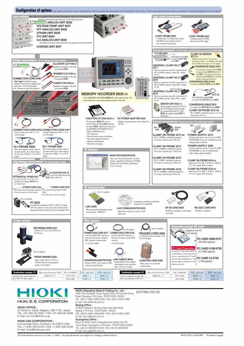
MEMORY HiCORDER 8835-01 * The MEMORY HiCORDER 8835-01 cannot operate alone. You
must install one or more optional input modules in the unit.
DC POWER ADAPTER 9439Supplies operating power in the range 10 to 28V DC.
Configuration of options Note: Options described as ”factory-installed options” must be specified when ordering and cannot be installed by the user. Note: Product names appearing in this catalog are trademarks or registered trademarks of various companies.
RECORDING PAPER 9221110 mm (4.33 in) × 30 m (98.43 ft), 10 rolls set
LAN CABLE 9642Straight Ethernet cable, supplied with straight to cross conversion cable, 5 m (16.41 ft) length
Input modules Input cables are not supplied. Please purchase the appropriate cable for the intended application.
PC Communication
Other optionsPrinter options
Install by inserting into the main unit. Can be replaced by user. ANALOG UNIT 8936VOLTAGE/TEMP UNIT 8937FFT ANALOG UNIT 8938STRAIN UNIT 8939F/V UNIT 89404ch ANALOG UNIT 8946 ...The 8946 can be used with the 8835-01, but cannot be used with the 8835.
CHARGE UNIT 8947
Combination example (1) Main unit with memory 4 MW No. of channels 2 ch + logic 16 ch 4 ch + logic 16 ch Combination example (2) Main unit with memory 4 MW No. of channels 4ch + logic 16ch 8ch + logic 16ch
(normal choice of the input unit, up to 200V AC direct input.)
8835-01 × 1 Input module 8936 × 1 8936 × 2 (select an automotive input unit that can handle up to 30 V AC.)
8835-01 × 1 Input module 8946 × 1 8946 × 2
Input cable 9198 × 2 9198 × 4 Input cable 9198 × 4 9198 × 8
LAN COMMUNICATOR 9333Application software to create a LAN connection
Compatible with Windows 95/98/Me, Windows NT 4.0/2000/XP
CARRYING CASE 9388With casters for convenient transportation.
PC Software
GP-IB CARD 9558PCMCIA-compliant, cord length: 2m (6.6ft)
RS-232C CARD 9557PCMCIA-compliant
LAN CARDMay not operate depending on the environment., 10BASE-T
Not CE marked
FUNCTION UP DISK 9540-01For the model 8835-01, use the FUNCTION UP DISK 9540 with the the model 8835. Additional functions to the MEMORY HiCORDER 8835-01 • REC & MEM functions• FFT functions• Waveform processing calculations • Waveform judgment function• Memory segmentation• Waveform averaging
Recommended
Logic signal measurement
LOGIC PROBE 93214 isolated channels, ON/OFF detection of AC/DC voltage
LOGIC PROBE 93204-channel type, for voltage/contact signal ON/OFF detection (response time 0.5 μsec, miniature terminal type)
Voltage measurement for use with general input modules
CONNECTION CORD 9790 (Thin Type) CAT II 300 V, ultra-
flexible 2.8 mm (0.11 in) diameter test lead cable, 1.5 m (4.92 ft) length
Note: Attachment clips sold separately.
ALLIGATOR CLIP 9790-01Red/black set attaches to the ends
of test leads (9790)
GRABBER CLIP 9790-02Red/black set attaches to the ends
of test leads (9790)
CONTACT PIN 9790-03
Red/black set attaches to the ends of test leads (9790)
CONNECTION CORD 9197For high voltage (up to 500 V), 1.8 m (5.91 ft) length
CONNECTION CORD 9198For low voltage (up to 300 V), 1.7 m (5.58 ft) length
10:1 PROBE 9665Max. rated voltage to earth is same as for input module, max. input voltage 1 kV rms (up to 500 kHz), 1.5 m (4.92 ft) length
100:1 PROBE 9666Max. rated voltage to earth is same as for input module, max. input voltage 5 kV peak (up to 1MHz), 1.5 m (4.92 ft) length
Recommended
Tip ExpandersAttachment clips are sold separately from CONNECTION CORD 9790.Purchase the appropriate attachment clips for your application separately
Tip Expanders9790-01
Tip Expanders9790-03
Tip Expanders9790-02
High-Voltage measurement for use with power supply
DIFFERENTIAL PROBE 9322For up to 2 kV DC or 1 kV AC. Use with either AC Adapter 9418-15, or via Power Cord.
AC ADAPTER 9418-15 For powering Differential probe 9322, 100 to 240 V AC
POWER CORD 9324 Use to the 9322 from the logic terminal.* Note that usage restrictions apply.
POWER CORD 9325 Use to the 9322 from the F/V UNIT
8940.* Note that usage restrictions apply.
Not CE marked
PAPER WINDER 220HPaper width 70mm (2.75 in) to 220mm (8.66 in), using special-purpose AC adapter
Not CE marked
WAVE PROCESSOR 9335Data conversion, print functions, waveform display, compatible with Windows 95/98/Me, Windows NT 4.0/2000/XP, and Windows Vista 32-bit type.
Removable storage (CF card)Supplied with PC Card adapter
PC CARD 256M 9727 (256 MB capacity)
PC CARD 512M 9728 (512 MB capacity)
PC CARD 1G 9729 (1 GB capacity)
PC Card PrecautionUse only PC Cards sold by HIOKI. Compatibility and performance are not guaranteed for PC cards made by other manufacturers. You may be unable to read from or save data to such cards.
CONNECTION CORD 9217Cord has insulated BNC connectors at both ends, and connects to insulated BNC connectors on input module. 1.7 m (5.58 ft) length
CONNECTION CORD 9165Cord has metallic BNC connectors at both ends, and connects to metallic BNC connectors. 1.5 m (4.92 ft) length
CONVERSION ADAPTER 9199 Banana-to-BNC, use to connect to BNC terminal on Input Module
Not CE marked
TRIGGER CORD 9305f 3.5mm (0.14in) mini-plug, 1.5m (4.92 ft) length
Not CE marked
32693273-503276
3274 3275
CLAMP ON PROBE 3273-50DC to 50MHz wideband response, mA-class current up to 30A rms
CLAMP ON PROBE 3274DC to 10MHz wideband response, mA-class current up to 150A rms
CLAMP ON PROBE 3275DC to 2MHz wideband response, mA-class current up to 500A rms
CLAMP ON PROBE 3276DC to 100MHz wideband response, mA-class current up to 30A rms
POWER SUPPLY 3272Connect and power up to one CLAMP ON PROBE to use in combination with voltage input modules
POWER SUPPLY 3269Connect and power up to four CLAMP ON PROBEs to use in combination with voltage input modules
3272
SENSOR UNIT 9555-10Power supply unit for the 9272 to the 9279 clamp sensors, except for connecting to the F/V unit 8940, for signal output 9217 is necessary.
CONVERSION CABLE 9318 (to connect the 9272 - 9279 and the 8940)
F/V UNIT 8940
UNIVERSAL CLAMP ON CT 9277
Observe waveforms from DC to distorted AC. DC to 100kHz response, input 20A / output 2V AC
UNIVERSAL CLAMP ON CT 9278
Observe waveforms from DC to distorted AC. DC to 100kHz response, input 200A / output 2V AC
UNIVERSAL CLAMP ON CT 9279
Observe waveforms from DC to distorted AC. DC to 20kHz response, input 500A / output 2V AC
Current measurement * The 3274, 3275, and 3276 cannot be used for the F/V UNIT 8940
CLAMP ON SENSOR 9272-10
Enables observation of AC current waveforms. Input: 1 to 100kHz, selectable 20 and 200A rms ranges, 2V AC output
CONVERSION CABLE 9705 Use with the Conversion Cable 9318
to connect Model 9272-10 to the F/V Unit 8940. (Not necessary for when using the Model 9272 due to different output wiring specifications.)
Not CE marked
CONVERSION CABLE 9318to connect the 9272 to 9279 and the 8940
CONVERSION CABLE 9319 to connect the 3273-50 and the 8940CLAMP ON PROBE 3273-50 DC to 50MHz wideband response, mA-class
current up to 30A rms
3273-50CONVERSION CABLE 9319 (to connect the 3273-50 and the 8940)
Current measurement *connect directly to the analog input module
CLAMP ON PROBE 9018-50Input from 10 to 500 A, 40 Hz to 3 kHz for 0.2 V AC output. BNC terminal
CLAMP ON PROBE 9132-50Input from 20 to 1000 A, 40 Hz to 1 kHz for 0.2 V AC output. BNC terminal
PT 9303Insulation transformer, 400V or 200V AC input, 10V AC output, for AC power line measurement. Required along with the Conversion Adapter 9199.