Embed Size (px)
Citation preview

1
Membrane-based water treatment to increase water supply
Alberto Tiraferri
Email. [email protected]
September 21, 2014
Direct link http://www.colloid.ch/membranes
In separation applications using membranes, the goal is to allow one or more components of a
mixture to permeate the membrane, while hindering permeation of other components. A nor-
mal filter meets this definition of a membrane, but, by convention, the term filter is usually lim-
ited to structures that separate components larger than roughly 1–10 μm. The term membrane is
used for separation of smaller compounds.
Membrane types. Most of the membranes used currently are anisotropic, see figure above
[1,2]. These membranes comprise a dense layer formed over a thicker porous support layer.
The separation properties and permeation rates of the membrane are determined exclusively by
the surface layer, while the substructure functions as a mechanical support. When the material
of the top layer and that of the porous sublayer are the same, the membrane is called an asym-
metric membrane. Asymmetric polymeric membranes are usually fabricated by a phase separa-
tion process [3,4]. On the other hand, if the material of the top layer is different from the mate-
rial of the porous sublayer, the membranes are called composite membranes, such as those cur-
rently used in nanofiltration (NF) and reverse osmosis (RO). The advantage of the composite
membrane over the asymmetric membrane is that the material for the top skin layer and the po-
rous sublayer can be chosen separately to optimize the overall performance [5].
Membrane processes. Membrane processes are divided based on the membrane type, what it
separates, the driving force used to create the chemical potential difference between the two
sides of the membrane, and the transport mechanism [1,2]. Here, we will focus on separation
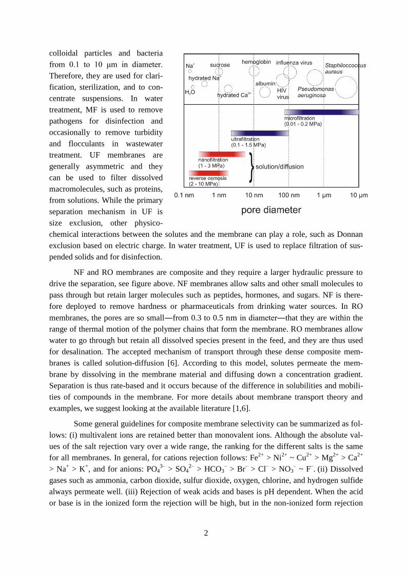
driven by a hydraulic trans-membrane pressure. Microfiltration (MF) and ultrafiltration (UF)
are similar in that the separation is mostly molecular sieving through the pores. These mem-
branes are illustrated in the right figure. MF membranes are usually symmetric and can filter
2
colloidal particles and bacteria
from 0.1 to 10 μm in diameter.
Therefore, they are used for clari-
fication, sterilization, and to con-
centrate suspensions. In water
treatment, MF is used to remove
pathogens for disinfection and
occasionally to remove turbidity
and flocculants in wastewater
treatment. UF membranes are
generally asymmetric and they
can be used to filter dissolved
macromolecules, such as proteins,
from solutions. While the primary
separation mechanism in UF is
size exclusion, other physico-
chemical interactions between the solutes and the membrane can play a role, such as Donnan
exclusion based on electric charge. In water treatment, UF is used to replace filtration of sus-
pended solids and for disinfection.
NF and RO membranes are composite and they require a larger hydraulic pressure to
drive the separation, see figure above. NF membranes allow salts and other small molecules to
pass through but retain larger molecules such as peptides, hormones, and sugars. NF is there-
fore deployed to remove hardness or pharmaceuticals from drinking water sources. In RO
membranes, the pores are so small―from 0.3 to 0.5 nm in diameter―that they are within the
range of thermal motion of the polymer chains that form the membrane. RO membranes allow
water to go through but retain all dissolved species present in the feed, and they are thus used
for desalination. The accepted mechanism of transport through these dense composite mem-
branes is called solution-diffusion [6]. According to this model, solutes permeate the mem-
brane by dissolving in the membrane material and diffusing down a concentration gradient.
Separation is thus rate-based and it occurs because of the difference in solubilities and mobili-
ties of compounds in the membrane. For more details about membrane transport theory and
examples, we suggest looking at the available literature [1,6].
Some general guidelines for composite membrane selectivity can be summarized as fol-
lows: (i) multivalent ions are retained better than monovalent ions. Although the absolute val-
ues of the salt rejection vary over a wide range, the ranking for the different salts is the same
for all membranes. In general, for cations rejection follows: Fe2+
> Ni2+
~ Cu2+
> Mg2+
> Ca2+
> Na+ > K
+, and for anions:
PO4
3– > SO4
2– > HCO3
– > Br
– > Cl
– > NO3
– ~ F
–. (ii) Dissolved
gases such as ammonia, carbon dioxide, sulfur dioxide, oxygen, chlorine, and hydrogen sulfide
always permeate well. (iii) Rejection of weak acids and bases is pH dependent. When the acid
or base is in the ionized form the rejection will be high, but in the non-ionized form rejection

3
will be low. (iv) Rejection of neutral organic solutes generally increases with the molecular
weight (or diameter) of the solute.
There are numerous technologies based on membrane separation. After a brief over-
view of fouling mechanisms and possible solutions to mitigate fouling, we will narrow our fo-
cus on processes for water and wastewater treatment that are being promisingly developed to
improve existing treatment schemes or to increase water supply beyond what is available from
the hydrological cycle. In particular, we will discuss wastewater recycling using membrane bi-
oreactors, and seawater desalination with reverse osmosis. We will briefly illustrate the poten-
tial of these two applications, as well as the current challenges related to their full-scale imple-
mentation.
Membrane fouling and cleaning
The major obstacle for the application of membrane processes is the rapid decline of the per-
meate flux over time as a result of membrane fouling. Fouling of membranes is caused by mass
transport of material to the membrane surface followed by adsorption and accumulation onto
the surface and/or within membrane pores [7].
Types of foulant. Raw waters contain a wide distribution of foulants, see figure below. Partic-
ulate fouling is caused by inorganic or organic particles that can deposit on the membrane sur-
face, block the pores, or hinder transport to the surface by the development of a cake layer.
Aquatic colloids comprise corrosion products, silt and clay, precipitated crystals, colloidal sili-
ca and sulfur, and precipitated iron and aluminum compounds. Some high molecular weight
organic substances, such as polysaccharide, proteins, and humic aggregates, are also character-
ized as colloidal foulants since many features of their behavior are common with those of inor-
ganic particles. The structure and mass of the deposited particulate cake layer are affected by
the particle-particle forces and by hydrodynamic conditions [8]. For example, under chemical
conditions in which particles repel each other and colloidal stability is maintained, the cake
layer is generally more porous, inducing lower
permeate flux decline. Such a cake layer will
also be easily removed from the membrane sur-
face during cleaning.
Organic fouling is the result of the ad-
sorption of dissolved components [9]. Dis-
solved organic matter is ubiquitous in surface
water, sewage, and secondary effluent of
wastewater treatment. In drinking water treat-
ment by MF and UF, natural organic matter
(NOM) has been identified as a major foulant
of polymeric membranes. NOM comprises a

4
range of compounds, from small hydrophobic acids, proteins and amino-acids to larger humic
and fulvic acids. There is evidence that the larger, less charged, and the more hydrophobic frac-
tion of NOM mostly contributes to irreversible organic fouling. This mechanism is consistent
with the general phenomenon of adsorption of polyelectrolytes and polymers on solid sub-
strates, which is faster and more pronounced in case of non-repulsive polymer-surface electro-
static interactions and due to hydrophobic forces. Adlayers of polymers are usually irreversibly
attached, such that chemical cleaning is necessary to induce desorption.
Scaling is another type of fouling related to dissolved ions that tend to precipitate onto
the membrane surface due to pH change or due to oxidation. Deposition is followed by crystal-
lization and crystal growth. Compounds commonly present in feed water and with a low solu-
bility are calcium carbonate (CaCO3), barium sulfate (BaSO4), silica (SiO2), and calcium sul-
fate (CaSO4). Antiscalant addition to the feed solution leads to a decline in the percent of area
covered by scale.
Finally, biofouling is caused by microbiological foulants, such as algae and bacteria,
which can adhere to the membranes and produce a biofilm [10]. Biofouling involves accumula-
tion of these biological organisms, their growth and metabolism on the membranes. Compo-
nents in the biofilm are the cell biomass and the various extracellular polymeric substances,
which behave in the same way as organic foulants. In all biofilms, the fraction of organic mac-
romolecules is usually the largest, accounting for 50–80% of the total organic matter and pro-
teins. Biofouling is arguably the major challenge when using RO for the reclamation of munic-
ipal effluents or for seawater desalination. Obviously, the extent and the type of fouling depend
strongly on the quality of the feed water and on operating conditions. Especially in the case of
complex water sources, different types of foulants will necessarily contribute simultaneously to
the formation of a mixed fouling layer.
Antifouling membranes. Efforts to mitigate fouling include pretreatment processes, the design
of new membrane modules, and the development of antifouling membranes. The separation
process by membrane is essentially a surface phenomenon. Therefore, it is a natural conse-
quence to modify membrane surface for reducing fouling. The membrane surface can be cus-
tomized to tailor the following properties [11,12]:
Surface hydrophilicity: it is generally accepted that an increase in hydrophilicity offers better
fouling resistance because many foulants, such as proteins, are hydrophobic in nature [13].
Surface charge: the repulsive forces working between the charged surface and the molecules of
the same charge in the feed solution prevent solute or particle deposition on the membrane sur-
face, thus reducing fouling. In reality, when the ionic strength of the feed water is high, electro-
static interactions are minimized, rendering the surface charge ineffective in terms of electro-
static repulsion. On the contrary, a detrimental phenomenon called bridging can occur if both
the membrane surface and the foulant molecule contain negatively-charged carboxyl groups
[14]. Bridging is caused by divalent calcium ions in solution cross-linking the carboxyls of the
membrane surface with the carboxyl groups of the fouling molecules, thus enhancing the at-

5
tachment of these molecules to the membrane surface. Polyamide membranes contain inherent
carboxyls at their surface, making this mechanism common during RO and NF operation.
Surface roughness: a smoother surface is commonly expected to experience less fouling, pre-
sumably because foulant particles are more likely to be entrained by rougher topologies than by
smoother membrane surfaces.
The effect of membrane surface modification on fouling is actually a debated topic. Some re-
searchers have experienced that membrane fouling can be reduced by modifying the membrane
surface only when the solution is dilute or only in the initial stage of the separation experiment.
Once the deposition of foulants has taken place, the surface properties can no longer play a role
in further deposition of foulants, which is then governed by foulant-foulant interactions. One
route for fouling prevention is to develop fouling release membranes that do not resist the ad-
hesion of foulants, but have an active layer with a low surface energy so that adhered foulants
can readily be washed away by hydrodynamic mixing in the membrane module. However, a
major challenge is to implement these chemistries such that the water flux and salt rejection of
the resulting membranes are not compromised [11].
Membrane cleaning. Once a fouling layer has developed, cleaning is necessary. Membrane
fouling can be classified as reversible fouling and irreversible fouling, of which the distinction
is entirely dependent on the context in which membranes are operated and cleaned. An easily
removable outer fouling layer is usually categorized as reversible. The performance of a mem-
brane with reversible fouling can be restored through appropriate physical washing protocol
such as backwashing or surface washing, while irreversible fouling can only be removed by
chemical cleaning, and sometimes cannot be removed at all. This means that the membranes
must go through extensive cleaning or be replaced.
Physical cleaning can be performed relatively often and involves a simple change in the
physical conditions of the system, for example increasing the hydrodynamics at the membrane-
solution interface by changing the flow conditions or by inserting air bubbles. Sometimes, even
simple changes in chemical conditions, such as temporary substitution of the feed solution with
a foulant-free solution ― often the permeate itself ― is regarded as physical cleaning. Howev-
er, irreversible fouling is inevitable. The long-term solution is to remove the foulant deposited
on membrane surfaces via chemical cleaning. There are five categories of cleaning agents —
alkaline solutions, acids, metal chelating agents, surfactants, and enzymes [15]. Commercial
cleaning products are often mixtures of these compounds. Alkaline solutions clean organic-
fouled membranes by hydrolysis and solubilization. Alkaline solutions increase the solution
pH, and therefore increase the negative charge and solubility of the organic foulant. For exam-
ple, when carboxylic functional groups of the organic foulant are completely deprotonated un-
der alkaline conditions, solubility increases by few orders of magnitude. In the presence of di-
valent cations, such as Ca2+
, carboxyl-rich foulants forms complexes with calcium ions, result-
ing in a highly compacted gel network of fouling layer. Metal chelating agents, such as eth-
ylenediaminetetraacetic acid (EDTA), remove divalent cations from the complexed organic
6
molecules and improve the cleaning of the fouled membrane. Finally, surfactants can form mi-
celles around macromolecules, solubilize them and help to remove the foulant from the mem-
brane surface. It has been shown that cleaning efficiencies with different cleaning agents are
consistent with related measurements of foulant–foulant intermolecular forces in the presence
of the agents, using the atomic force microscopy [16]. Virtually, the optimal cleaning agent
mixture and concentration could be derived from measurements of foulant–foulant adhesion
force, even before membranes are put in operation. For favorably reactive cleaning agents,
cleaning efficiency can be further improved by enhancing the mass transfer of the reaction
products from the fouling layer to the bulk solution. Nevertheless, repeated chemical cleaning
will eventually result in wear and tear and eventual loss of membrane properties.
Wastewater recycling using membrane bioreactors
By recycling wastewater, the circulation of water through the natural water cycle can be short-
circuited, such that production of water for human needs has a smaller impact on environmen-
tal resources. Reuse encompasses any type of beneficial use of recycled water, from restricted
agricultural irrigation all the way to unrestricted residential use for potable water [17].
Wastewater treatment is based on the removal of solids in suspension, soluble organic com-
pounds, and nutrients, such as phosphorus and nitrogen. A common way to degrade and re-
move most of the contaminants from wastewater is using the activated sludge process. This
technology consists in biodegradation of the pretreated influent by microorganisms followed by
a clarification in a settling tank to ensure the separation of the treated water from the biomass.
Although this technique may appear robust and safe, the treated water quality is dependent on
the settling properties of the biological suspension and the treatment efficiency is usually lim-
ited by the difficulties in separating suspended solids [18]. Furthermore, this process requires
large aeration and sedimentation tanks, and it generates large quantities of sludge. Membrane
technology can play an important role to overcome some of the problems associated with tradi-
tional processes, such as activated sludge.
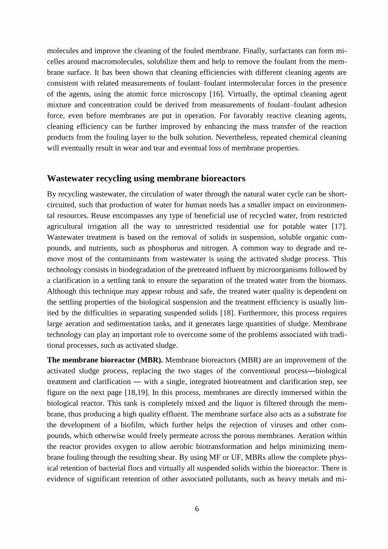
The membrane bioreactor (MBR). Membrane bioreactors (MBR) are an improvement of the
activated sludge process, replacing the two stages of the conventional process―biological
treatment and clarification ― with a single, integrated biotreatment and clarification step, see
figure on the next page [18,19]. In this process, membranes are directly immersed within the
biological reactor. This tank is completely mixed and the liquor is filtered through the mem-
brane, thus producing a high quality effluent. The membrane surface also acts as a substrate for
the development of a biofilm, which further helps the rejection of viruses and other com-
pounds, which otherwise would freely permeate across the porous membranes. Aeration within
the reactor provides oxygen to allow aerobic biotransformation and helps minimizing mem-
brane fouling through the resulting shear. By using MF or UF, MBRs allow the complete phys-
ical retention of bacterial flocs and virtually all suspended solids within the bioreactor. There is
evidence of significant retention of other associated pollutants, such as heavy metals and mi-
7
cropollutants, although not always below the required concentrations. Removal of these con-
taminants is allowed by the long sludge retention time. Since degradation in MBR is largely
dominated by the biological component, bioaugmentation helps achieving higher removal,
which is related to the biodegradability of the individual compound. Due to the absence of sec-
ondary clarifier and the possibility to use a high sludge concentration, the overall size of the
treatment plant can be reduced significantly if MBR is used instead of activated sludge.
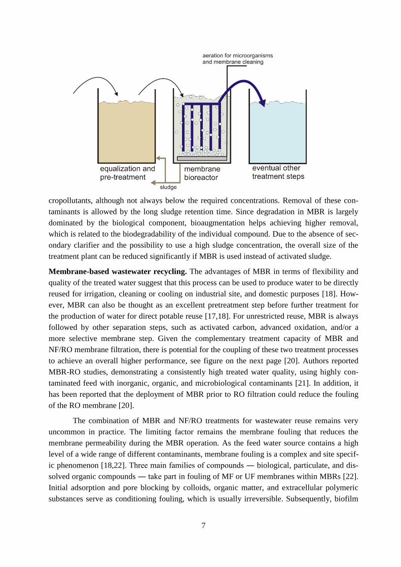
Membrane-based wastewater recycling. The advantages of MBR in terms of flexibility and
quality of the treated water suggest that this process can be used to produce water to be directly
reused for irrigation, cleaning or cooling on industrial site, and domestic purposes [18]. How-
ever, MBR can also be thought as an excellent pretreatment step before further treatment for
the production of water for direct potable reuse [17,18]. For unrestricted reuse, MBR is always
followed by other separation steps, such as activated carbon, advanced oxidation, and/or a
more selective membrane step. Given the complementary treatment capacity of MBR and
NF/RO membrane filtration, there is potential for the coupling of these two treatment processes
to achieve an overall higher performance, see figure on the next page [20]. Authors reported
MBR-RO studies, demonstrating a consistently high treated water quality, using highly con-
taminated feed with inorganic, organic, and microbiological contaminants [21]. In addition, it
has been reported that the deployment of MBR prior to RO filtration could reduce the fouling
of the RO membrane [20].
The combination of MBR and NF/RO treatments for wastewater reuse remains very
uncommon in practice. The limiting factor remains the membrane fouling that reduces the
membrane permeability during the MBR operation. As the feed water source contains a high
level of a wide range of different contaminants, membrane fouling is a complex and site specif-
ic phenomenon [18,22]. Three main families of compounds ― biological, particulate, and dis-
solved organic compounds ― take part in fouling of MF or UF membranes within MBRs [22].
Initial adsorption and pore blocking by colloids, organic matter, and extracellular polymeric
substances serve as conditioning fouling, which is usually irreversible. Subsequently, biofilm
8
growth and cake formation further decrease the system productivity, but can be considered as
reversible fouling. Deposition of solids and high-molecular weight compounds can be usually
controlled during the operation by means of high shear stress at the membrane surface, relaxa-
tion periods, or back flushing [18]. The fabrication of antifouling membranes would virtually
allow the development of a single-stage MBR with an immersed tight nanofiltration membrane,
which would replace the two stages of MBR and NF/RO processes [20]. Recently, osmotic
MBR technology based on forward osmosis has been suggested to mitigate fouling and to en-
hance the overall process performance [23,24].
Case study. An interesting case study about the implementation of MBR technology for the
reuse of wastewater is that of Japan. Initially, the Japanese government promoted the reclama-
tion of wastewater in the mega cities of Fukuoka and Tokyo. City legislation required large
buildings and commercial facilities to adopt water saving measures including rainwater har-
vesting and in-building greywater treatment and reuse systems. This initiative was followed by
the issue of strict water quality standards for reclaimed wastewater, which required the adop-
tion of advance technologies for reclamation. The Aqua Renaissance program '90 led to devel-
opment of MBR systems by companies such as Kubota and Mitsubishi, resulting in the later
demonstration and adoption of MBR processes both in remodeled existing facilities and in new
satellite sewage treatment, within the project A-JUMP. Here, MBR processes have shown sig-
nificant advantages over alternative biological treatment processes, particularly in terms of
pathogen removal and process robustness. Nowadays, a high percentage of the worldwide
MBR systems are installed in Japan for in-building greywater treatment, with the aim of re-
stricted residential use.
While wastewater reuse represents one of possible solutions to the growing pressure on water
resources, its implementation is hindered by technical, economical, and legislation issues, as
well as public awareness and, most importantly, acceptance. Some authors have underlined that
we are technically capable of treating wastewater to any quality we desire simply by ―filtering
it through money‖ [17]. If money is available, technology usually allows the production of safe
water with negligible levels of any contaminants. However, the level of treatment will be com-
promise between the nature and concentration of contaminants, the specific beneficial use of
the treated water, and the related water quality standards and treatment costs to achieve them.

9
Furthermore, reuse of wastewater usually requires major capital investment, not only related to
the treatment facility, but associated to the installation of a dual piping system, to careful con-
trol of effluent quality, and to additional precautions to minimize health and environmental
risks [17]. Therefore, beneficial recycling of wastewater relies on a paradigm shift in the way
we think about waste and commodity, and it is a political issue as much as it is a scientific
challenge.
Seawater desalination using reverse osmosis
Reverse osmosis desalination scheme. Membrane desalination by reverse osmosis is the fast-
est growing desalination technology. Seawater has a salt concentration of 32-40 g/L, depending
on the region of the world. The osmotic pressure of seawater is about 350 psi (24 bar), and the
osmotic pressure of the rejected brine can be as much as 600 psi (41 bar), so osmotic pressure
affects the net operating pressure in a plant markedly. Currently, all new seawater desalination
plants are based on interfacial composite membranes with the dense layer made of polyamide
of the fully aromatic type. Typical thin-film composite polyamide membranes, tested with
3.5% sodium chloride solutions, have a salt rejection of 99.5% and a water flux of 0.5 L m–2
h–1
at 800 psi [11]. The key steps of a desalination system are shown in the figure below.
These steps are (i) seawater intake, including the structures and strategies used to extract sea-
water and convey it to the process system, (ii) pretreatment, defined as the removal of suspend-
ed solids and control of biological growth, often performed using UF: this step may entail addi-
tion of chlorine-based disinfectants and subsequent dechlorination before the desalination step,
as well as addition of antiscalants; (iii) desalination, the process that removes dissolved ions in
RO: removal of boron below the required concentration may require a second RO pass; (iv)
post-treatment, including the addition of chemicals to the product water to prevent corrosion of
downstream infrastructure piping and to improve taste; (v) brine discharge and management,
the handling and disposal or reuse of waste residuals from the desalination system. Utilization
of the residual pressure of the brine leaving the RO membrane module is a necessary step to
recover otherwise wasted discharged energy.

10
Energy input of seawater desalination by RO. The minimum amount of energy required to
separate pure water from seawater is a benchmark for comparison of the efficiency of current
desalination schemes and can guide efforts to reduce energy demand [11]. This theoretical min-
imum energy, which is independent of the desalination method, is realized when the separation
occurs as a reversible thermodynamic process. When two solutions of different composition are
mixed (or separated), the Gibbs free energy of mixing is released (or needed). Separating an
infinitely small amount of pure water from
seawater requires approximately
0.76 kWh/m3 of work; see right figure.
This work is equivalent to the minimum
energy to desalinate seawater at 0% re-
covery. If the salinity of seawater or if the
desired water recovery increases, so does
the minimum energy required for desali-
nation. The change in Gibbs free energy
represents a lower bound on the energy
that is needed to desalinate, regardless of
the pathway. However, the second law of
thermodynamics dictates that the actual
energy needed is always more than the
theoretical one. In the theoretical reversi-
ble thermodynamic RO model, an infini-
tesimal water flux is maintained through-
out the process. This is achieved by virtu-
ally applying a hydraulic pressure negligi-
bly larger than the osmotic pressure dif-
ference on the feed solution such that an
infinitesimally small volume of pure water
permeates across the membrane. In this
reversible thermodynamic RO process, no
entropy is generated. For a usual 50% re-
covery, the ideal energy value required to
achieve desalination equals 1.06 kWh/m3.
Unlike in the reversible RO process, a net
constant driving pressure equal to the final
osmotic pressure of the concentrated feed
is required to maintain a nonzero permeate
flux. When the applied pressure is equal to
the osmotic pressure of the concentrate,
the system is said to be operating at the
thermodynamic limit. Therefore, regard-

11
less of how permeable a membrane is, the energy consumption is set by the need to bring the
feed volume to a pressure equal to the osmotic pressure of the concentrate [11]. The RO desali-
nation step at 50% recovery has a practical minimum energy of 1.56 kWh/m3. Thus, 0.5
kWh/m3 is expended because the system has a finite size and is not operating as a reversible
thermodynamic process. In reality, an extra amount of energy is needed to overcome concen-
tration polarization. This ideal energy consumption of 1.56 kWh/m3 is not far from reported
energy consumptions of 2–2.5 kWh/m3 of current well-designed RO systems, see figure on the
previous page.
Costs of RO seawater desalination. The surface properties of thin-film composite polyamide
membranes make them prone to fouling, which diminishes process performance. Biofouling is
the fouling mechanisms that mostly impair the performance of the RO desalination step. Bio-
film formation could potentially be prevented if chlorine or other oxidants were added to the
feed. However, polyamide films undergo a permanent loss in performance resulting from expo-
sure to even ppb levels of these disinfectants. Therefore, good pretreatment of the raw water
before it is fed into the RO stage is essential. While the energy demand for seawater desalina-
tion by state-of-the-art reverse osmosis is not far from the theoretical minimum energy for de-
salination, the overall energy consumption of overall RO plants is roughly four times higher
than this theoretical minimum due to the need for extensive pretreatment, which account for
almost 1 kWh/m3. The development of fouling-resistant membranes would improve the energy
efficiency of desalination by RO. However, no membrane yet exists that possesses both high
separation performances and antifouling properties [11]. Energy is the largest single variable
cost for desalination as shown in the figure on the previous page. Ashkelon desalination plant,
the largest seawater RO plant in the world, was built at a cost of more than USD 200.000.000,
and produces drinking water at a price of approximately USD 0.6 USD/m3.
Seawater desalination, like any other major industrial process, has environmental impacts that
must be understood and mitigated. These impacts include effects associated with the construc-
tion of the plant but, especially, the effects of withdrawing large volumes of seawater from the
ocean and discharging large volumes of highly concentrated brine. There is presently a consid-
erable amount of uncertainty about the environmental impacts of desalination. Each desalina-
tion facility must be individually evaluated in the context of location, plant design, and local
environmental conditions.
List of Acronyms
MBR Membrane bioreactor
MF Microfiltration
NF Nanofiltration
NOM Natural organic matter
RO Reverse osmosis
UF Ultrafiltration
12
First posted, September 21, 2014. Last revision, January 5, 2015.
This work is licensed under a Creative Commons Attribution 4.0 International License.
References
[1] Baker R. (2004) Membrane technology and applications, 2nd ed., Wiley.
[2] Mulder J. (1996) Basic principles of membrane technology. 2nd ed., Springer.
[3] Tiraferri A., Yip N. Y., Phillip W. A., Schiffman J. D., Elimelech M. (2011) Relating per-
formance of thin-film composite forward osmosis membranes to support layer formation and
structure, J. Membrane Sci. 367, 340-352, 10.1016/j.memsci.2010.11.014.
[4] Wijmans J. G., Baaij J. P. B., Smolders C. A. (1983) The mechanism of formation of mi-
croporous or skinned membranes produced by immersion precipitation, J. Membrane Sci. 14,
263-274, 10.1016/0376-7388(83)80005-2.
[5] Petersen R. J. (1993) Composite Reverse-Osmosis and Nanofiltration Membranes, J.
Membrane Sci. 83, 81-150, 10.1016/0376-7388(93)80014-O.
[6] Wijmans J. G., Baker R. W. (1995) The solution-diffusion model - a review, J. Membrane
Sci. 107, 1-21, http://dx.doi.org/10.1016/0376-7388(95)00102-I.
[7] Goosen M. F. A., Sablani S. S., Ai-Hinai H., Ai-Obeidani S., Al-Belushi R., Jackson D.
(2004) Fouling of reverse osmosis and ultrafiltration membranes: A critical review, Sep. Sci.
Technol. 39, 2261-2297, 10.1081/Ss-120039343.
[8] Song L. F., Elimelech M. (1995) Theory of concentration polarization in cross-flow filtra-
tion, J. Chem. Soc. Faraday Trans. 91, 3389-3398, 10.1039/Ft9959103389.
[9] Hong S. K., Elimelech M. (1997) Chemical and physical aspects of natural organic matter
(NOM) fouling of nanofiltration membranes, J. Membrane Sci. 132, 159-181,
10.1016/S0376-7388(97)00060-4.
[10] Watnick P., Kolter R. (2000) Biofilm, city of microbes, J. Bacteriol. 182, 2675-2679,
10.1128/Jb.182.10.2675-2679.2000.
[11] Elimelech M., Phillip W. A. (2011) The future of seawater desalination: Energy, tech-
nology, and the environment, Science 333, 712-717, 10.1126/science.1200488.
[12] Rana D., Matsuura T. (2010) Surface modifications for antifouling membranes, Chem.
Rev. 110, 2448-2471, 10.1021/Cr800208y.
[13] Tiraferri A., Kang Y., Giannelis E. P., Elimelech M. (2012) Superhydrophilic thin-film
composite forward osmosis membranes for organic fouling control: Fouling behavior and an-
tifouling mechanisms, Environ. Sci. Technol. 46, 11135-11144, 10.1021/es3028617.

13
[14] Mo Y. H., Tiraferri A., Yip N. Y., Adout A., Huang X., Elimelech M. (2012) Improved
antifouling properties of polyamide nanofiltration membranes by reducing the density of sur-
face carboxyl groups, Environ. Sci. Technol. 46, 13253-13261, 10.1021/es303673p.
[15] Ang W. S., Lee S. Y., Elimelech, M. (2016) Chemical and physical aspects of cleaning
of organic-fouled reverse osmosis membranes, J. Membrane Sci. 272, 198-210,
10.1016/j.memsci.2005.07.035.
[16] Ang W. S., Tiraferri A., Chen K. L., Elimelech, M. (2011) Fouling and cleaning of RO
membranes fouled by mixtures of organic foulants simulating wastewater effluent. J. Mem-
brane Sci. 376, 196-206, 10.1016/j.memsci.2011.04.020.
[17] Wintgens T., Melin T., Schafer A., Khan S., Muston M., Bixio D., Thoeye C. (2005) The
role of membrane processes in municipal wastewater reclamation and reuse, Desalination
178, 1-11, 10.1016/j.desal.2004.12.014.
[18] Wisniewski C. (2007) Membrane bioreactor for water reuse, Desalination 203, 15-19,
10.1016/j.desal.2006.05.002.
[19] Judd S. (2006) The MBR book, Elsevier.
[20] Shannon M. A., Bohn P. W., Elimelech M., Georgiadis J. G., Marinas B. J., Mayes A.
M. (2008) Science and technology for water purification in the coming decades, Nature 452,
301-310, 10.1038/Nature06599.
[21] Alturki A. A., Tadkaew N., McDonald J. A., Khan S. J., Price W. E., Nghiem L. D.
(2010) Combining MBR and NF/RO membrane filtration for the removal of trace organics in
indirect potable water reuse applications. J. Membrane Sci. 365, 206-215,
10.1016/j.memsci.2010.09.008.
[22] Le-Clech P., Chen V., Fane T. A. G. (2006) Fouling in membrane bioreactors used in
wastewater treatment. J. Membrane Sci. 284, 17-53, 10.1016/j.memsci.2006.08.019.
[23] Achilli A., Cath T. Y., Marchand E. A., Childress A. E. (2009) The forward osmosis
membrane bioreactor: A low fouling alternative to MBR processes. Desalination 239, 10-21,
10.1016/j.desal.2008.02.022.
[24] Yap W. J., Zhang J. S., Lay W. C. L., Cao B., Fane A. G., Liu Y. (2012) State of the art
of osmotic membrane bioreactors for water reclamation. Bioresource Technol. 122, 217-222,
10.1016/j.biortech.2012.03.060.