Embed Size (px)
Citation preview
Members Subjected to Flexural Loads
Introduction:
In many engineering structures members are required to resist forces that are applied laterally or transversely to their axes. These type of members are termed as beam.
There are various ways to define the beams such as
Definition I: A beam is a laterally loaded member, whose cross-sectional dimensions are small as compared to its length.
Definition II: A beam is nothing simply a bar which is subjected to forces or couples that lie in a plane containing the longitudnal axis of the bar. The forces are understood to act perpendicular to the longitudnal axis of the bar.
Definition III: A bar working under bending is generally termed as a beam.
Materials for Beam:
The beams may be made from several usable engineering materials such commonly among them are as follows:
Metal
Wood
Concrete
Plastic
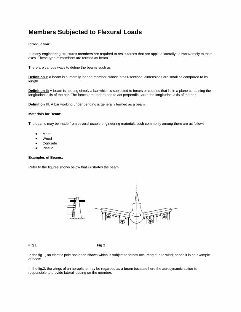
Examples of Beams:
Refer to the figures shown below that illustrates the beam
Fig 1 Fig 2
In the fig.1, an electric pole has been shown which is subject to forces occurring due to wind; hence it is an example of beam.
In the fig.2, the wings of an aeroplane may be regarded as a beam because here the aerodynamic action is responsible to provide lateral loading on the member.
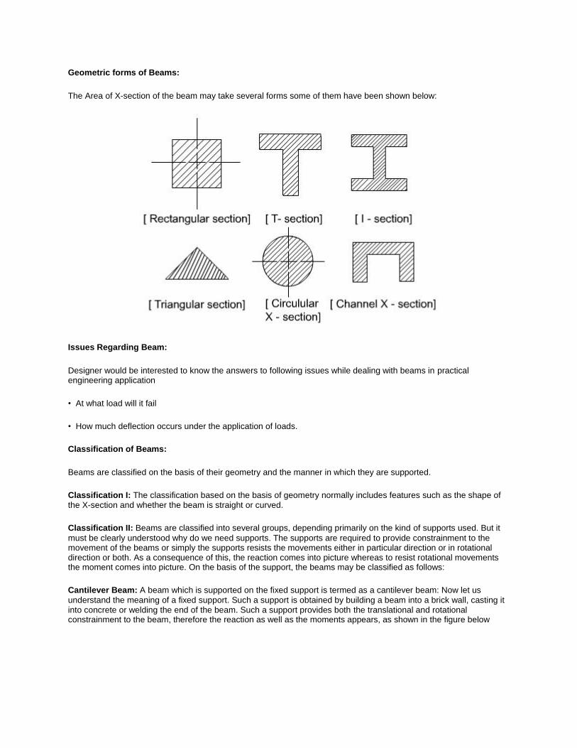
Geometric forms of Beams:
The Area of X-section of the beam may take several forms some of them have been shown below:
Issues Regarding Beam:
Designer would be interested to know the answers to following issues while dealing with beams in practical engineering application
• At what load will it fail
• How much deflection occurs under the application of loads.
Classification of Beams:
Beams are classified on the basis of their geometry and the manner in which they are supported.
Classification I: The classification based on the basis of geometry normally includes features such as the shape of the X-section and whether the beam is straight or curved.
Classification II: Beams are classified into several groups, depending primarily on the kind of supports used. But it
must be clearly understood why do we need supports. The supports are required to provide constrainment to the movement of the beams or simply the supports resists the movements either in particular direction or in rotational direction or both. As a consequence of this, the reaction comes into picture whereas to resist rotational movements the moment comes into picture. On the basis of the support, the beams may be classified as follows:
Cantilever Beam: A beam which is supported on the fixed support is termed as a cantilever beam: Now let us
understand the meaning of a fixed support. Such a support is obtained by building a beam into a brick wall, casting it into concrete or welding the end of the beam. Such a support provides both the translational and rotational constrainment to the beam, therefore the reaction as well as the moments appears, as shown in the figure below

Simply Supported Beam: The beams are said to be simply supported if their supports creates only the translational
constraints.
Some times the translational movement may be allowed in one direction with the help of rollers and can be represented like this
Statically Determinate or Statically Indeterminate Beams:
The beams can also be categorized as statically determinate or else it can be referred as statically indeterminate. If all the external forces and moments acting on it can be determined from the equilibrium conditions alone then. It would be referred as a statically determinate beam, whereas in the statically indeterminate beams one has to consider deformation i.e. deflections to solve the problem.
Types of loads acting on beams:
A beam is normally horizontal where as the external loads acting on the beams is generally in the vertical directions. In order to study the behaviors of beams under flexural loads. It becomes pertinent that one must be familiar with the various types of loads acting on the beams as well as their physical manifestations.
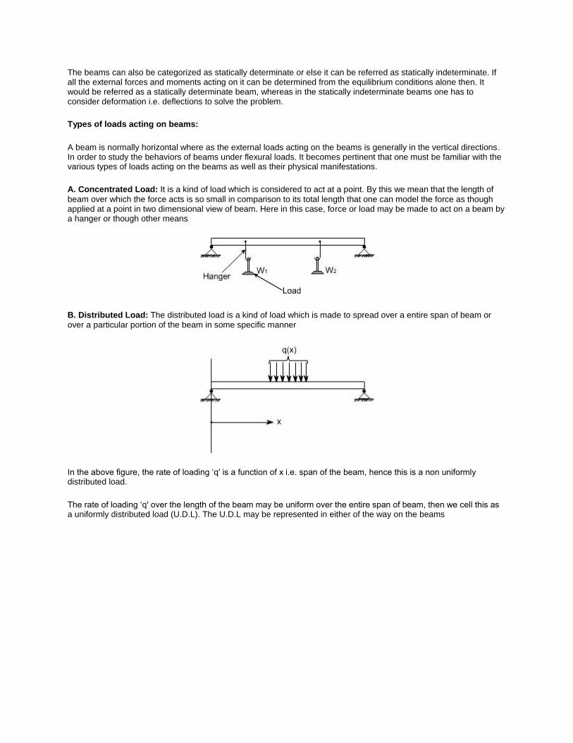
A. Concentrated Load: It is a kind of load which is considered to act at a point. By this we mean that the length of
beam over which the force acts is so small in comparison to its total length that one can model the force as though applied at a point in two dimensional view of beam. Here in this case, force or load may be made to act on a beam by a hanger or though other means
B. Distributed Load: The distributed load is a kind of load which is made to spread over a entire span of beam or over a particular portion of the beam in some specific manner
In the above figure, the rate of loading ‘q' is a function of x i.e. span of the beam, hence this is a non uniformly distributed load.
The rate of loading ‘q' over the length of the beam may be uniform over the entire span of beam, then we cell this as a uniformly distributed load (U.D.L). The U.D.L may be represented in either of the way on the beams

some times the load acting on the beams may be the uniformly varying as in the case of dams or on inclind wall of a vessel containing liquid, then this may be represented on the beam as below:
The U.D.L can be easily realized by making idealization of the ware house load, where the bags of grains are placed over a beam.
Concentrated Moment:
The beam may be subjected to a concentrated moment essentially at a point. One of the possible arrangement for applying the moment is being shown in the figure below:

oncept of Shear Force and Bending moment in beams:
When the beam is loaded in some arbitrarily manner, the internal forces and moments are developed and the terms shear force and bending moments come into pictures which are helpful to analyze the beams further. Let us define these terms
Fig 1

Now let us consider the beam as shown in fig 1(a) which is supporting the loads P1, P2, P3 and is simply supported at two points creating the reactions R1 and R2 respectively. Now let us assume that the beam is to divided into or imagined to be cut into two portions at a section AA. Now let us assume that the resultant of loads and reactions to the left of AA is ‘F' vertically upwards, and since the entire beam is to remain in equilibrium, thus the resultant of forces to the right of AA must also be F, acting downwards. This forces ‘F' is as a shear force. The shearing force at any x-section of a beam represents the tendency for the portion of the beam to one side of the section to slide or shear laterally relative to the other portion.
Therefore, now we are in a position to define the shear force ‘F' to as follows:
At any x-section of a beam, the shear force ‘F' is the algebraic sum of all the lateral components of the forces acting on either side of the x-section.
Sign Convention for Shear Force:
The usual sign conventions to be followed for the shear forces have been illustrated in figures 2 and 3.
Fig 2: Positive Shear Force

Fig 3: Negative Shear Force
Bending Moment:
Fig 4
Let us again consider the beam which is simply supported at the two prints, carrying loads P1, P2 and P3 and having the reactions R1 and R2 at the supports Fig 4. Now, let us imagine that the beam is cut into two potions at the x-
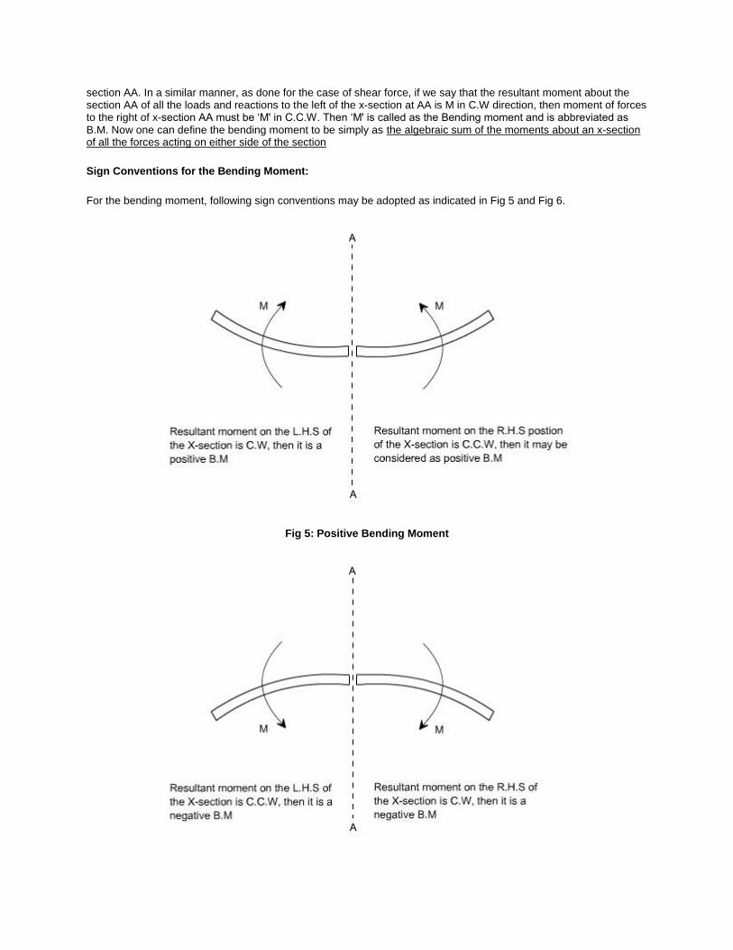
section AA. In a similar manner, as done for the case of shear force, if we say that the resultant moment about the section AA of all the loads and reactions to the left of the x-section at AA is M in C.W direction, then moment of forces to the right of x-section AA must be ‘M' in C.C.W. Then ‘M' is called as the Bending moment and is abbreviated as B.M. Now one can define the bending moment to be simply as the algebraic sum of the moments about an x-section of all the forces acting on either side of the section
Sign Conventions for the Bending Moment:
For the bending moment, following sign conventions may be adopted as indicated in Fig 5 and Fig 6.
Fig 5: Positive Bending Moment

Fig 6: Negative Bending Moment
Some times, the terms ‘Sagging' and Hogging are generally used for the positive and negative bending moments respectively.
Bending Moment and Shear Force Diagrams:
The diagrams which illustrate the variations in B.M and S.F values along the length of the beam for any fixed loading conditions would be helpful to analyze the beam further.
Thus, a shear force diagram is a graphical plot, which depicts how the internal shear force ‘F' varies along the length of beam. If x dentotes the length of the beam, then F is function x i.e. F(x).
Similarly a bending moment diagram is a graphical plot which depicts how the internal bending moment ‘M' varies along the length of the beam. Again M is a function x i.e. M(x).
Basic Relationship Between The Rate of Loading, Shear Force and Bending Moment:
The construction of the shear force diagram and bending moment diagrams is greatly simplified if the relationship among load, shear force and bending moment is established.
Let us consider a simply supported beam AB carrying a uniformly distributed load w/length. Let us imagine to cut a short slice of length dx cut out from this loaded beam at distance ‘x' from the origin ‘0'.
Let us detach this portion of the beam and draw its free body diagram.
The forces acting on the free body diagram of the detached portion of this loaded beam are the following
• The shearing force F and F+ F at the section x and x + x respectively.
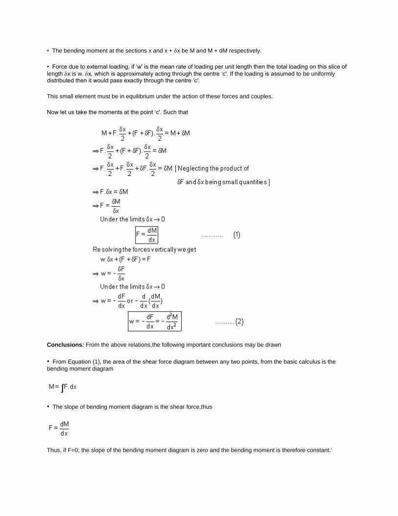
• The bending moment at the sections x and x + x be M and M + dM respectively.
• Force due to external loading, if ‘w' is the mean rate of loading per unit length then the total loading on this slice of
length x is w. x, which is approximately acting through the centre ‘c'. If the loading is assumed to be uniformly distributed then it would pass exactly through the centre ‘c'.
This small element must be in equilibrium under the action of these forces and couples.
Now let us take the moments at the point ‘c'. Such that
Conclusions: From the above relations,the following important conclusions may be drawn
• From Equation (1), the area of the shear force diagram between any two points, from the basic calculus is the
bending moment diagram
• The slope of bending moment diagram is the shear force,thus
Thus, if F=0; the slope of the bending moment diagram is zero and the bending moment is therefore constant.'

• The maximum or minimum Bending moment occurs where
The slope of the shear force diagram is equal to the magnitude of the intensity of the distributed loading at any position along the beam. The –ve sign is as a consequence of our particular choice of sign conventions
Source: http://nptel.ac.in/courses/Webcourse-contents/IIT-
ROORKEE/strength%20of%20materials/homepage.htm


![Paper ID. [CE207]librarian/Question Papers/B.Tech...Q7) Derive an expression for crippling load when both the ends of the column are hinged. Q8) Drawthe S.F. and B.M. diagram for a](https://img.dokumen.tips/doc/110x75/607828b89b7c893cc37087e0/paper-id-ce207-librarianquestion-papersbtech-q7-derive-an-expression-for.jpg)